EP3978551B1 - Procédé de production d'un corps moulé en resine et procédé permettant d'augmenter la defibration des nanofibres de cellulose pendant la production du corps moule en resine - Google Patents
Procédé de production d'un corps moulé en resine et procédé permettant d'augmenter la defibration des nanofibres de cellulose pendant la production du corps moule en resine Download PDFInfo
- Publication number
- EP3978551B1 EP3978551B1 EP20814095.4A EP20814095A EP3978551B1 EP 3978551 B1 EP3978551 B1 EP 3978551B1 EP 20814095 A EP20814095 A EP 20814095A EP 3978551 B1 EP3978551 B1 EP 3978551B1
- Authority
- EP
- European Patent Office
- Prior art keywords
- supply material
- mass
- molded body
- cellulose nanofibers
- resin molded
- Prior art date
- Legal status (The legal status is an assumption and is not a legal conclusion. Google has not performed a legal analysis and makes no representation as to the accuracy of the status listed.)
- Active
Links
- 239000011347 resin Substances 0.000 title claims description 213
- 229920005989 resin Polymers 0.000 title claims description 213
- 239000001913 cellulose Substances 0.000 title claims description 162
- 229920002678 cellulose Polymers 0.000 title claims description 162
- 239000002121 nanofiber Substances 0.000 title claims description 138
- 238000000034 method Methods 0.000 title claims description 89
- 238000004519 manufacturing process Methods 0.000 title claims description 28
- 239000000463 material Substances 0.000 claims description 270
- 238000000465 moulding Methods 0.000 claims description 79
- 239000000155 melt Substances 0.000 claims description 72
- 239000008188 pellet Substances 0.000 claims description 61
- 229920005992 thermoplastic resin Polymers 0.000 claims description 58
- 239000011342 resin composition Substances 0.000 claims description 50
- 239000000203 mixture Substances 0.000 claims description 48
- 238000002156 mixing Methods 0.000 claims description 42
- 238000002844 melting Methods 0.000 claims description 28
- 230000008018 melting Effects 0.000 claims description 28
- 229920002647 polyamide Polymers 0.000 claims description 27
- 239000000835 fiber Substances 0.000 claims description 25
- 238000004898 kneading Methods 0.000 claims description 18
- 239000004952 Polyamide Substances 0.000 claims description 16
- 238000006467 substitution reaction Methods 0.000 claims description 16
- 239000000470 constituent Substances 0.000 claims description 15
- 235000010980 cellulose Nutrition 0.000 description 146
- -1 poly(methyl methacrylate) Polymers 0.000 description 44
- 239000000047 product Substances 0.000 description 28
- 230000008569 process Effects 0.000 description 20
- 238000011068 loading method Methods 0.000 description 19
- 239000004743 Polypropylene Substances 0.000 description 18
- 230000000052 comparative effect Effects 0.000 description 17
- QTBSBXVTEAMEQO-UHFFFAOYSA-N Acetic acid Chemical compound CC(O)=O QTBSBXVTEAMEQO-UHFFFAOYSA-N 0.000 description 15
- 239000003795 chemical substances by application Substances 0.000 description 15
- 230000000704 physical effect Effects 0.000 description 15
- 229920002292 Nylon 6 Polymers 0.000 description 14
- 230000000694 effects Effects 0.000 description 14
- 239000002245 particle Substances 0.000 description 13
- 229920005672 polyolefin resin Polymers 0.000 description 13
- 238000001746 injection moulding Methods 0.000 description 11
- 239000012948 isocyanate Substances 0.000 description 11
- 229920001155 polypropylene Polymers 0.000 description 11
- 239000003963 antioxidant agent Substances 0.000 description 10
- 239000002981 blocking agent Substances 0.000 description 10
- 239000003921 oil Substances 0.000 description 10
- XLYOFNOQVPJJNP-UHFFFAOYSA-N water Substances O XLYOFNOQVPJJNP-UHFFFAOYSA-N 0.000 description 10
- 230000003078 antioxidant effect Effects 0.000 description 9
- 229920001577 copolymer Polymers 0.000 description 9
- FERIUCNNQQJTOY-UHFFFAOYSA-N Butyric acid Chemical compound CCCC(O)=O FERIUCNNQQJTOY-UHFFFAOYSA-N 0.000 description 8
- RTZKZFJDLAIYFH-UHFFFAOYSA-N Diethyl ether Chemical compound CCOCC RTZKZFJDLAIYFH-UHFFFAOYSA-N 0.000 description 8
- ISWSIDIOOBJBQZ-UHFFFAOYSA-N Phenol Chemical compound OC1=CC=CC=C1 ISWSIDIOOBJBQZ-UHFFFAOYSA-N 0.000 description 8
- 239000002253 acid Substances 0.000 description 8
- WPYMKLBDIGXBTP-UHFFFAOYSA-N benzoic acid Chemical compound OC(=O)C1=CC=CC=C1 WPYMKLBDIGXBTP-UHFFFAOYSA-N 0.000 description 8
- XBDQKXXYIPTUBI-UHFFFAOYSA-N dimethylselenoniopropionate Natural products CCC(O)=O XBDQKXXYIPTUBI-UHFFFAOYSA-N 0.000 description 8
- POULHZVOKOAJMA-UHFFFAOYSA-N dodecanoic acid Chemical compound CCCCCCCCCCCC(O)=O POULHZVOKOAJMA-UHFFFAOYSA-N 0.000 description 8
- IPCSVZSSVZVIGE-UHFFFAOYSA-N hexadecanoic acid Chemical compound CCCCCCCCCCCCCCCC(O)=O IPCSVZSSVZVIGE-UHFFFAOYSA-N 0.000 description 8
- FUZZWVXGSFPDMH-UHFFFAOYSA-N hexanoic acid Chemical compound CCCCCC(O)=O FUZZWVXGSFPDMH-UHFFFAOYSA-N 0.000 description 8
- 125000002887 hydroxy group Chemical group [H]O* 0.000 description 8
- 238000005259 measurement Methods 0.000 description 8
- WWZKQHOCKIZLMA-UHFFFAOYSA-N octanoic acid Chemical compound CCCCCCCC(O)=O WWZKQHOCKIZLMA-UHFFFAOYSA-N 0.000 description 8
- 230000009257 reactivity Effects 0.000 description 8
- 239000007858 starting material Substances 0.000 description 8
- SZHOJFHSIKHZHA-UHFFFAOYSA-N tridecanoic acid Chemical compound CCCCCCCCCCCCC(O)=O SZHOJFHSIKHZHA-UHFFFAOYSA-N 0.000 description 8
- NQPDZGIKBAWPEJ-UHFFFAOYSA-N valeric acid Chemical compound CCCCC(O)=O NQPDZGIKBAWPEJ-UHFFFAOYSA-N 0.000 description 8
- 150000001875 compounds Chemical class 0.000 description 7
- 238000010586 diagram Methods 0.000 description 7
- 239000000314 lubricant Substances 0.000 description 7
- 229920001225 polyester resin Polymers 0.000 description 7
- 239000005056 polyisocyanate Chemical class 0.000 description 7
- 229920001228 polyisocyanate Chemical class 0.000 description 7
- 229920000642 polymer Polymers 0.000 description 7
- 239000002002 slurry Substances 0.000 description 7
- WFDIJRYMOXRFFG-UHFFFAOYSA-N Acetic anhydride Chemical compound CC(=O)OC(C)=O WFDIJRYMOXRFFG-UHFFFAOYSA-N 0.000 description 6
- 125000003178 carboxy group Chemical group [H]OC(*)=O 0.000 description 6
- 239000003153 chemical reaction reagent Substances 0.000 description 6
- 229920001955 polyphenylene ether Polymers 0.000 description 6
- 150000007513 acids Chemical class 0.000 description 5
- 125000002947 alkylene group Chemical group 0.000 description 5
- 239000011324 bead Substances 0.000 description 5
- GYZLOYUZLJXAJU-UHFFFAOYSA-N diglycidyl ether Chemical class C1OC1COCC1CO1 GYZLOYUZLJXAJU-UHFFFAOYSA-N 0.000 description 5
- 239000006185 dispersion Substances 0.000 description 5
- 238000001125 extrusion Methods 0.000 description 5
- 238000005227 gel permeation chromatography Methods 0.000 description 5
- 238000002360 preparation method Methods 0.000 description 5
- 238000012545 processing Methods 0.000 description 5
- 239000008213 purified water Substances 0.000 description 5
- UPMLOUAZCHDJJD-UHFFFAOYSA-N 4,4'-Diphenylmethane Diisocyanate Chemical compound C1=CC(N=C=O)=CC=C1CC1=CC=C(N=C=O)C=C1 UPMLOUAZCHDJJD-UHFFFAOYSA-N 0.000 description 4
- PAYRUJLWNCNPSJ-UHFFFAOYSA-N Aniline Chemical compound NC1=CC=CC=C1 PAYRUJLWNCNPSJ-UHFFFAOYSA-N 0.000 description 4
- 239000005711 Benzoic acid Substances 0.000 description 4
- 239000005635 Caprylic acid (CAS 124-07-2) Substances 0.000 description 4
- IAZDPXIOMUYVGZ-UHFFFAOYSA-N Dimethylsulphoxide Chemical compound CS(C)=O IAZDPXIOMUYVGZ-UHFFFAOYSA-N 0.000 description 4
- 239000005639 Lauric acid Substances 0.000 description 4
- 235000021314 Palmitic acid Nutrition 0.000 description 4
- 229930182556 Polyacetal Natural products 0.000 description 4
- 239000002202 Polyethylene glycol Substances 0.000 description 4
- 235000021355 Stearic acid Nutrition 0.000 description 4
- WYURNTSHIVDZCO-UHFFFAOYSA-N Tetrahydrofuran Chemical group C1CCOC1 WYURNTSHIVDZCO-UHFFFAOYSA-N 0.000 description 4
- 239000002168 alkylating agent Substances 0.000 description 4
- 229940100198 alkylating agent Drugs 0.000 description 4
- 229920006127 amorphous resin Polymers 0.000 description 4
- 235000010233 benzoic acid Nutrition 0.000 description 4
- HQABUPZFAYXKJW-UHFFFAOYSA-N butan-1-amine Chemical compound CCCCN HQABUPZFAYXKJW-UHFFFAOYSA-N 0.000 description 4
- 229920006038 crystalline resin Polymers 0.000 description 4
- 238000005520 cutting process Methods 0.000 description 4
- NZNMSOFKMUBTKW-UHFFFAOYSA-N cyclohexanecarboxylic acid Chemical compound OC(=O)C1CCCCC1 NZNMSOFKMUBTKW-UHFFFAOYSA-N 0.000 description 4
- PAFZNILMFXTMIY-UHFFFAOYSA-N cyclohexylamine Chemical compound NC1CCCCC1 PAFZNILMFXTMIY-UHFFFAOYSA-N 0.000 description 4
- 238000009826 distribution Methods 0.000 description 4
- 125000003055 glycidyl group Chemical group C(C1CO1)* 0.000 description 4
- FFUAGWLWBBFQJT-UHFFFAOYSA-N hexamethyldisilazane Chemical compound C[Si](C)(C)N[Si](C)(C)C FFUAGWLWBBFQJT-UHFFFAOYSA-N 0.000 description 4
- 239000011256 inorganic filler Substances 0.000 description 4
- 229910003475 inorganic filler Inorganic materials 0.000 description 4
- KQNPFQTWMSNSAP-UHFFFAOYSA-N isobutyric acid Chemical compound CC(C)C(O)=O KQNPFQTWMSNSAP-UHFFFAOYSA-N 0.000 description 4
- 230000004048 modification Effects 0.000 description 4
- 238000012986 modification Methods 0.000 description 4
- 239000000178 monomer Substances 0.000 description 4
- WQEPLUUGTLDZJY-UHFFFAOYSA-N n-Pentadecanoic acid Natural products CCCCCCCCCCCCCCC(O)=O WQEPLUUGTLDZJY-UHFFFAOYSA-N 0.000 description 4
- QIQXTHQIDYTFRH-UHFFFAOYSA-N octadecanoic acid Chemical compound CCCCCCCCCCCCCCCCCC(O)=O QIQXTHQIDYTFRH-UHFFFAOYSA-N 0.000 description 4
- OQCDKBAXFALNLD-UHFFFAOYSA-N octadecanoic acid Natural products CCCCCCCC(C)CCCCCCCCC(O)=O OQCDKBAXFALNLD-UHFFFAOYSA-N 0.000 description 4
- 229960002446 octanoic acid Drugs 0.000 description 4
- 150000002894 organic compounds Chemical class 0.000 description 4
- WLJVXDMOQOGPHL-UHFFFAOYSA-N phenylacetic acid Chemical compound OC(=O)CC1=CC=CC=C1 WLJVXDMOQOGPHL-UHFFFAOYSA-N 0.000 description 4
- XNGIFLGASWRNHJ-UHFFFAOYSA-N phthalic acid Chemical compound OC(=O)C1=CC=CC=C1C(O)=O XNGIFLGASWRNHJ-UHFFFAOYSA-N 0.000 description 4
- 229920002961 polybutylene succinate Polymers 0.000 description 4
- 239000004631 polybutylene succinate Substances 0.000 description 4
- 229920009537 polybutylene succinate adipate Polymers 0.000 description 4
- 239000004630 polybutylene succinate adipate Substances 0.000 description 4
- 229920001707 polybutylene terephthalate Polymers 0.000 description 4
- 229920001223 polyethylene glycol Polymers 0.000 description 4
- 229920006324 polyoxymethylene Polymers 0.000 description 4
- 235000019260 propionic acid Nutrition 0.000 description 4
- IUVKMZGDUIUOCP-BTNSXGMBSA-N quinbolone Chemical compound O([C@H]1CC[C@H]2[C@H]3[C@@H]([C@]4(C=CC(=O)C=C4CC3)C)CC[C@@]21C)C1=CCCC1 IUVKMZGDUIUOCP-BTNSXGMBSA-N 0.000 description 4
- 239000007787 solid Substances 0.000 description 4
- 239000008117 stearic acid Substances 0.000 description 4
- 239000006228 supernatant Substances 0.000 description 4
- 239000012756 surface treatment agent Substances 0.000 description 4
- TUNFSRHWOTWDNC-HKGQFRNVSA-N tetradecanoic acid Chemical compound CCCCCCCCCCCCC[14C](O)=O TUNFSRHWOTWDNC-HKGQFRNVSA-N 0.000 description 4
- 229940005605 valeric acid Drugs 0.000 description 4
- PBKONEOXTCPAFI-UHFFFAOYSA-N 1,2,4-trichlorobenzene Chemical compound ClC1=CC=C(Cl)C(Cl)=C1 PBKONEOXTCPAFI-UHFFFAOYSA-N 0.000 description 3
- 238000005160 1H NMR spectroscopy Methods 0.000 description 3
- WSFSSNUMVMOOMR-UHFFFAOYSA-N Formaldehyde Chemical compound O=C WSFSSNUMVMOOMR-UHFFFAOYSA-N 0.000 description 3
- 239000005057 Hexamethylene diisocyanate Substances 0.000 description 3
- OKKJLVBELUTLKV-UHFFFAOYSA-N Methanol Chemical compound OC OKKJLVBELUTLKV-UHFFFAOYSA-N 0.000 description 3
- ZMXDDKWLCZADIW-UHFFFAOYSA-N N,N-Dimethylformamide Chemical compound CN(C)C=O ZMXDDKWLCZADIW-UHFFFAOYSA-N 0.000 description 3
- 238000005481 NMR spectroscopy Methods 0.000 description 3
- OAICVXFJPJFONN-UHFFFAOYSA-N Phosphorus Chemical compound [P] OAICVXFJPJFONN-UHFFFAOYSA-N 0.000 description 3
- KDYFGRWQOYBRFD-UHFFFAOYSA-N Succinic acid Natural products OC(=O)CCC(O)=O KDYFGRWQOYBRFD-UHFFFAOYSA-N 0.000 description 3
- YXFVVABEGXRONW-UHFFFAOYSA-N Toluene Chemical compound CC1=CC=CC=C1 YXFVVABEGXRONW-UHFFFAOYSA-N 0.000 description 3
- 150000008065 acid anhydrides Chemical class 0.000 description 3
- 125000002723 alicyclic group Chemical group 0.000 description 3
- 150000008064 anhydrides Chemical class 0.000 description 3
- 230000000903 blocking effect Effects 0.000 description 3
- 230000008859 change Effects 0.000 description 3
- KRKNYBCHXYNGOX-UHFFFAOYSA-N citric acid Chemical compound OC(=O)CC(O)(C(O)=O)CC(O)=O KRKNYBCHXYNGOX-UHFFFAOYSA-N 0.000 description 3
- 238000010276 construction Methods 0.000 description 3
- 230000001186 cumulative effect Effects 0.000 description 3
- 238000013461 design Methods 0.000 description 3
- 125000005442 diisocyanate group Chemical group 0.000 description 3
- 238000005516 engineering process Methods 0.000 description 3
- 239000000446 fuel Substances 0.000 description 3
- 239000011521 glass Substances 0.000 description 3
- 239000003365 glass fiber Substances 0.000 description 3
- RRAMGCGOFNQTLD-UHFFFAOYSA-N hexamethylene diisocyanate Chemical compound O=C=NCCCCCCN=C=O RRAMGCGOFNQTLD-UHFFFAOYSA-N 0.000 description 3
- 229910052739 hydrogen Inorganic materials 0.000 description 3
- 239000001257 hydrogen Substances 0.000 description 3
- RAXXELZNTBOGNW-UHFFFAOYSA-N imidazole Natural products C1=CNC=N1 RAXXELZNTBOGNW-UHFFFAOYSA-N 0.000 description 3
- 230000002401 inhibitory effect Effects 0.000 description 3
- 230000003287 optical effect Effects 0.000 description 3
- 239000011574 phosphorus Substances 0.000 description 3
- 229910052698 phosphorus Inorganic materials 0.000 description 3
- 229920000139 polyethylene terephthalate Polymers 0.000 description 3
- 239000005020 polyethylene terephthalate Substances 0.000 description 3
- 238000006116 polymerization reaction Methods 0.000 description 3
- 239000000843 powder Substances 0.000 description 3
- 238000010298 pulverizing process Methods 0.000 description 3
- 230000003014 reinforcing effect Effects 0.000 description 3
- 239000012779 reinforcing material Substances 0.000 description 3
- 239000000454 talc Substances 0.000 description 3
- 229910052623 talc Inorganic materials 0.000 description 3
- 238000012360 testing method Methods 0.000 description 3
- DVKJHBMWWAPEIU-UHFFFAOYSA-N toluene 2,4-diisocyanate Chemical compound CC1=CC=C(N=C=O)C=C1N=C=O DVKJHBMWWAPEIU-UHFFFAOYSA-N 0.000 description 3
- VZCYOOQTPOCHFL-UHFFFAOYSA-N trans-butenedioic acid Natural products OC(=O)C=CC(O)=O VZCYOOQTPOCHFL-UHFFFAOYSA-N 0.000 description 3
- 238000011144 upstream manufacturing Methods 0.000 description 3
- 239000004711 α-olefin Substances 0.000 description 3
- FKTHNVSLHLHISI-UHFFFAOYSA-N 1,2-bis(isocyanatomethyl)benzene Chemical class O=C=NCC1=CC=CC=C1CN=C=O FKTHNVSLHLHISI-UHFFFAOYSA-N 0.000 description 2
- WNXJIVFYUVYPPR-UHFFFAOYSA-N 1,3-dioxolane Chemical compound C1COCO1 WNXJIVFYUVYPPR-UHFFFAOYSA-N 0.000 description 2
- MNDIARAMWBIKFW-UHFFFAOYSA-N 1-bromohexane Chemical compound CCCCCCBr MNDIARAMWBIKFW-UHFFFAOYSA-N 0.000 description 2
- BMVXCPBXGZKUPN-UHFFFAOYSA-N 1-hexanamine Chemical compound CCCCCCN BMVXCPBXGZKUPN-UHFFFAOYSA-N 0.000 description 2
- UWLHSHAHTBJTBA-UHFFFAOYSA-N 1-iodooctane Chemical compound CCCCCCCCI UWLHSHAHTBJTBA-UHFFFAOYSA-N 0.000 description 2
- SNGZGCFWZHOVOS-UHFFFAOYSA-N 2-(2-methyloctoxymethyl)oxirane Chemical compound CCCCCCC(C)COCC1CO1 SNGZGCFWZHOVOS-UHFFFAOYSA-N 0.000 description 2
- FALRKNHUBBKYCC-UHFFFAOYSA-N 2-(chloromethyl)pyridine-3-carbonitrile Chemical compound ClCC1=NC=CC=C1C#N FALRKNHUBBKYCC-UHFFFAOYSA-N 0.000 description 2
- WTYYGFLRBWMFRY-UHFFFAOYSA-N 2-[6-(oxiran-2-ylmethoxy)hexoxymethyl]oxirane Chemical compound C1OC1COCCCCCCOCC1CO1 WTYYGFLRBWMFRY-UHFFFAOYSA-N 0.000 description 2
- PLDLPVSQYMQDBL-UHFFFAOYSA-N 2-[[3-(oxiran-2-ylmethoxy)-2,2-bis(oxiran-2-ylmethoxymethyl)propoxy]methyl]oxirane Chemical compound C1OC1COCC(COCC1OC1)(COCC1OC1)COCC1CO1 PLDLPVSQYMQDBL-UHFFFAOYSA-N 0.000 description 2
- GJYCVCVHRSWLNY-UHFFFAOYSA-N 2-butylphenol Chemical group CCCCC1=CC=CC=C1O GJYCVCVHRSWLNY-UHFFFAOYSA-N 0.000 description 2
- ZSPDYGICHBLYSD-UHFFFAOYSA-N 2-methylnaphthalene-1-carboxylic acid Chemical compound C1=CC=CC2=C(C(O)=O)C(C)=CC=C21 ZSPDYGICHBLYSD-UHFFFAOYSA-N 0.000 description 2
- UOBYKYZJUGYBDK-UHFFFAOYSA-N 2-naphthoic acid Chemical compound C1=CC=CC2=CC(C(=O)O)=CC=C21 UOBYKYZJUGYBDK-UHFFFAOYSA-N 0.000 description 2
- VTYYLEPIZMXCLO-UHFFFAOYSA-L Calcium carbonate Chemical compound [Ca+2].[O-]C([O-])=O VTYYLEPIZMXCLO-UHFFFAOYSA-L 0.000 description 2
- 229920000049 Carbon (fiber) Polymers 0.000 description 2
- HEDRZPFGACZZDS-UHFFFAOYSA-N Chloroform Chemical compound ClC(Cl)Cl HEDRZPFGACZZDS-UHFFFAOYSA-N 0.000 description 2
- MHZGKXUYDGKKIU-UHFFFAOYSA-N Decylamine Chemical compound CCCCCCCCCCN MHZGKXUYDGKKIU-UHFFFAOYSA-N 0.000 description 2
- ROSDSFDQCJNGOL-UHFFFAOYSA-N Dimethylamine Chemical compound CNC ROSDSFDQCJNGOL-UHFFFAOYSA-N 0.000 description 2
- VGGSQFUCUMXWEO-UHFFFAOYSA-N Ethene Chemical compound C=C VGGSQFUCUMXWEO-UHFFFAOYSA-N 0.000 description 2
- QUSNBJAOOMFDIB-UHFFFAOYSA-N Ethylamine Chemical compound CCN QUSNBJAOOMFDIB-UHFFFAOYSA-N 0.000 description 2
- 239000005977 Ethylene Substances 0.000 description 2
- LYCAIKOWRPUZTN-UHFFFAOYSA-N Ethylene glycol Chemical compound OCCO LYCAIKOWRPUZTN-UHFFFAOYSA-N 0.000 description 2
- IAYPIBMASNFSPL-UHFFFAOYSA-N Ethylene oxide Chemical compound C1CO1 IAYPIBMASNFSPL-UHFFFAOYSA-N 0.000 description 2
- VZCYOOQTPOCHFL-OWOJBTEDSA-N Fumaric acid Chemical compound OC(=O)\C=C\C(O)=O VZCYOOQTPOCHFL-OWOJBTEDSA-N 0.000 description 2
- DHMQDGOQFOQNFH-UHFFFAOYSA-N Glycine Chemical compound NCC(O)=O DHMQDGOQFOQNFH-UHFFFAOYSA-N 0.000 description 2
- 229920002488 Hemicellulose Polymers 0.000 description 2
- UQSXHKLRYXJYBZ-UHFFFAOYSA-N Iron oxide Chemical compound [Fe]=O UQSXHKLRYXJYBZ-UHFFFAOYSA-N 0.000 description 2
- BAVYZALUXZFZLV-UHFFFAOYSA-N Methylamine Chemical compound NC BAVYZALUXZFZLV-UHFFFAOYSA-N 0.000 description 2
- 229920000571 Nylon 11 Polymers 0.000 description 2
- 229920000299 Nylon 12 Polymers 0.000 description 2
- 229920002302 Nylon 6,6 Polymers 0.000 description 2
- 229920000572 Nylon 6/12 Polymers 0.000 description 2
- REYJJPSVUYRZGE-UHFFFAOYSA-N Octadecylamine Chemical compound CCCCCCCCCCCCCCCCCCN REYJJPSVUYRZGE-UHFFFAOYSA-N 0.000 description 2
- LGRFSURHDFAFJT-UHFFFAOYSA-N Phthalic anhydride Natural products C1=CC=C2C(=O)OC(=O)C2=C1 LGRFSURHDFAFJT-UHFFFAOYSA-N 0.000 description 2
- 229920003171 Poly (ethylene oxide) Polymers 0.000 description 2
- 239000004734 Polyphenylene sulfide Substances 0.000 description 2
- 239000004793 Polystyrene Substances 0.000 description 2
- OFOBLEOULBTSOW-UHFFFAOYSA-N Propanedioic acid Natural products OC(=O)CC(O)=O OFOBLEOULBTSOW-UHFFFAOYSA-N 0.000 description 2
- UIIMBOGNXHQVGW-UHFFFAOYSA-M Sodium bicarbonate Chemical compound [Na+].OC([O-])=O UIIMBOGNXHQVGW-UHFFFAOYSA-M 0.000 description 2
- QAOWNCQODCNURD-UHFFFAOYSA-N Sulfuric acid Chemical compound OS(O)(=O)=O QAOWNCQODCNURD-UHFFFAOYSA-N 0.000 description 2
- KKEYFWRCBNTPAC-UHFFFAOYSA-N Terephthalic acid Chemical compound OC(=O)C1=CC=C(C(O)=O)C=C1 KKEYFWRCBNTPAC-UHFFFAOYSA-N 0.000 description 2
- GWEVSGVZZGPLCZ-UHFFFAOYSA-N Titan oxide Chemical compound O=[Ti]=O GWEVSGVZZGPLCZ-UHFFFAOYSA-N 0.000 description 2
- DTQVDTLACAAQTR-UHFFFAOYSA-N Trifluoroacetic acid Chemical compound OC(=O)C(F)(F)F DTQVDTLACAAQTR-UHFFFAOYSA-N 0.000 description 2
- XTXRWKRVRITETP-UHFFFAOYSA-N Vinyl acetate Chemical compound CC(=O)OC=C XTXRWKRVRITETP-UHFFFAOYSA-N 0.000 description 2
- XLOMVQKBTHCTTD-UHFFFAOYSA-N Zinc monoxide Chemical compound [Zn]=O XLOMVQKBTHCTTD-UHFFFAOYSA-N 0.000 description 2
- MCMNRKCIXSYSNV-UHFFFAOYSA-N Zirconium dioxide Chemical compound O=[Zr]=O MCMNRKCIXSYSNV-UHFFFAOYSA-N 0.000 description 2
- 238000005299 abrasion Methods 0.000 description 2
- 125000000218 acetic acid group Chemical group C(C)(=O)* 0.000 description 2
- WNLRTRBMVRJNCN-UHFFFAOYSA-N adipic acid Chemical compound OC(=O)CCCCC(O)=O WNLRTRBMVRJNCN-UHFFFAOYSA-N 0.000 description 2
- 125000001931 aliphatic group Chemical group 0.000 description 2
- HPTYUNKZVDYXLP-UHFFFAOYSA-N aluminum;trihydroxy(trihydroxysilyloxy)silane;hydrate Chemical compound O.[Al].[Al].O[Si](O)(O)O[Si](O)(O)O HPTYUNKZVDYXLP-UHFFFAOYSA-N 0.000 description 2
- 150000001412 amines Chemical class 0.000 description 2
- 125000003118 aryl group Chemical group 0.000 description 2
- TZCXTZWJZNENPQ-UHFFFAOYSA-L barium sulfate Chemical compound [Ba+2].[O-]S([O-])(=O)=O TZCXTZWJZNENPQ-UHFFFAOYSA-L 0.000 description 2
- 230000008901 benefit Effects 0.000 description 2
- 229920001400 block copolymer Polymers 0.000 description 2
- JHIWVOJDXOSYLW-UHFFFAOYSA-N butyl 2,2-difluorocyclopropane-1-carboxylate Chemical compound CCCCOC(=O)C1CC1(F)F JHIWVOJDXOSYLW-UHFFFAOYSA-N 0.000 description 2
- 239000004917 carbon fiber Substances 0.000 description 2
- 150000001735 carboxylic acids Chemical class 0.000 description 2
- 230000001413 cellular effect Effects 0.000 description 2
- 238000005119 centrifugation Methods 0.000 description 2
- 239000002131 composite material Substances 0.000 description 2
- VZFUCHSFHOYXIS-UHFFFAOYSA-N cycloheptane carboxylic acid Natural products OC(=O)C1CCCCCC1 VZFUCHSFHOYXIS-UHFFFAOYSA-N 0.000 description 2
- 230000006866 deterioration Effects 0.000 description 2
- JQVDAXLFBXTEQA-UHFFFAOYSA-N dibutylamine Chemical compound CCCCNCCCC JQVDAXLFBXTEQA-UHFFFAOYSA-N 0.000 description 2
- DMBHHRLKUKUOEG-UHFFFAOYSA-N diphenylamine Chemical compound C=1C=CC=CC=1NC1=CC=CC=C1 DMBHHRLKUKUOEG-UHFFFAOYSA-N 0.000 description 2
- 238000010494 dissociation reaction Methods 0.000 description 2
- 230000005593 dissociations Effects 0.000 description 2
- 239000003480 eluent Substances 0.000 description 2
- JBKVHLHDHHXQEQ-UHFFFAOYSA-N epsilon-caprolactam Chemical group O=C1CCCCCN1 JBKVHLHDHHXQEQ-UHFFFAOYSA-N 0.000 description 2
- 150000002148 esters Chemical class 0.000 description 2
- RSIHJDGMBDPTIM-UHFFFAOYSA-N ethoxy(trimethyl)silane Chemical compound CCO[Si](C)(C)C RSIHJDGMBDPTIM-UHFFFAOYSA-N 0.000 description 2
- 230000006870 function Effects 0.000 description 2
- 125000000524 functional group Chemical group 0.000 description 2
- 230000009477 glass transition Effects 0.000 description 2
- JFCQEDHGNNZCLN-UHFFFAOYSA-N glutaric acid Chemical compound OC(=O)CCCC(O)=O JFCQEDHGNNZCLN-UHFFFAOYSA-N 0.000 description 2
- 229910052621 halloysite Inorganic materials 0.000 description 2
- 230000003301 hydrolyzing effect Effects 0.000 description 2
- 230000002209 hydrophobic effect Effects 0.000 description 2
- 238000002347 injection Methods 0.000 description 2
- 239000007924 injection Substances 0.000 description 2
- IQPQWNKOIGAROB-UHFFFAOYSA-N isocyanate group Chemical group [N-]=C=O IQPQWNKOIGAROB-UHFFFAOYSA-N 0.000 description 2
- 150000002513 isocyanates Chemical class 0.000 description 2
- 150000003951 lactams Chemical class 0.000 description 2
- 238000007561 laser diffraction method Methods 0.000 description 2
- VZCYOOQTPOCHFL-UPHRSURJSA-N maleic acid Chemical compound OC(=O)\C=C/C(O)=O VZCYOOQTPOCHFL-UPHRSURJSA-N 0.000 description 2
- 239000011976 maleic acid Substances 0.000 description 2
- FPYJFEHAWHCUMM-UHFFFAOYSA-N maleic anhydride Chemical compound O=C1OC(=O)C=C1 FPYJFEHAWHCUMM-UHFFFAOYSA-N 0.000 description 2
- 230000007246 mechanism Effects 0.000 description 2
- RUFRLNPHRPYBLF-UHFFFAOYSA-N methoxy-dimethyl-octadecylsilane Chemical compound CCCCCCCCCCCCCCCCCC[Si](C)(C)OC RUFRLNPHRPYBLF-UHFFFAOYSA-N 0.000 description 2
- BAXHQTUUOKMMGV-UHFFFAOYSA-N methoxy-dimethyl-octylsilane Chemical compound CCCCCCCC[Si](C)(C)OC BAXHQTUUOKMMGV-UHFFFAOYSA-N 0.000 description 2
- 125000002496 methyl group Chemical group [H]C([H])([H])* 0.000 description 2
- 239000010445 mica Substances 0.000 description 2
- 229910052618 mica group Inorganic materials 0.000 description 2
- BDJRBEYXGGNYIS-UHFFFAOYSA-N nonanedioic acid Chemical compound OC(=O)CCCCCCCC(O)=O BDJRBEYXGGNYIS-UHFFFAOYSA-N 0.000 description 2
- ZWLPBLYKEWSWPD-UHFFFAOYSA-N o-toluic acid Chemical compound CC1=CC=CC=C1C(O)=O ZWLPBLYKEWSWPD-UHFFFAOYSA-N 0.000 description 2
- IOQPZZOEVPZRBK-UHFFFAOYSA-N octan-1-amine Chemical compound CCCCCCCCN IOQPZZOEVPZRBK-UHFFFAOYSA-N 0.000 description 2
- 229960003424 phenylacetic acid Drugs 0.000 description 2
- 239000003279 phenylacetic acid Substances 0.000 description 2
- WLJVNTCWHIRURA-UHFFFAOYSA-N pimelic acid Chemical compound OC(=O)CCCCCC(O)=O WLJVNTCWHIRURA-UHFFFAOYSA-N 0.000 description 2
- IUGYQRQAERSCNH-UHFFFAOYSA-N pivalic acid Chemical compound CC(C)(C)C(O)=O IUGYQRQAERSCNH-UHFFFAOYSA-N 0.000 description 2
- 239000004629 polybutylene adipate terephthalate Substances 0.000 description 2
- 229920000515 polycarbonate Polymers 0.000 description 2
- 239000004417 polycarbonate Substances 0.000 description 2
- 239000011112 polyethylene naphthalate Substances 0.000 description 2
- 229920000069 polyphenylene sulfide Polymers 0.000 description 2
- 229920001451 polypropylene glycol Polymers 0.000 description 2
- 229920002223 polystyrene Polymers 0.000 description 2
- WGYKZJWCGVVSQN-UHFFFAOYSA-N propylamine Chemical compound CCCN WGYKZJWCGVVSQN-UHFFFAOYSA-N 0.000 description 2
- 238000004064 recycling Methods 0.000 description 2
- 238000000790 scattering method Methods 0.000 description 2
- CXMXRPHRNRROMY-UHFFFAOYSA-N sebacic acid Chemical compound OC(=O)CCCCCCCCC(O)=O CXMXRPHRNRROMY-UHFFFAOYSA-N 0.000 description 2
- 239000000243 solution Substances 0.000 description 2
- 239000002904 solvent Substances 0.000 description 2
- 238000003756 stirring Methods 0.000 description 2
- TYFQFVWCELRYAO-UHFFFAOYSA-N suberic acid Chemical compound OC(=O)CCCCCCC(O)=O TYFQFVWCELRYAO-UHFFFAOYSA-N 0.000 description 2
- 229940014800 succinic anhydride Drugs 0.000 description 2
- 239000000725 suspension Substances 0.000 description 2
- YLQBMQCUIZJEEH-UHFFFAOYSA-N tetrahydrofuran Natural products C=1C=COC=1 YLQBMQCUIZJEEH-UHFFFAOYSA-N 0.000 description 2
- JNYAEWCLZODPBN-JGWLITMVSA-N (2r,3r,4s)-2-[(1r)-1,2-dihydroxyethyl]oxolane-3,4-diol Chemical compound OC[C@@H](O)[C@H]1OC[C@H](O)[C@H]1O JNYAEWCLZODPBN-JGWLITMVSA-N 0.000 description 1
- BYEAHWXPCBROCE-UHFFFAOYSA-N 1,1,1,3,3,3-hexafluoropropan-2-ol Chemical group FC(F)(F)C(O)C(F)(F)F BYEAHWXPCBROCE-UHFFFAOYSA-N 0.000 description 1
- GFNDFCFPJQPVQL-UHFFFAOYSA-N 1,12-diisocyanatododecane Chemical compound O=C=NCCCCCCCCCCCCN=C=O GFNDFCFPJQPVQL-UHFFFAOYSA-N 0.000 description 1
- XSCLFFBWRKTMTE-UHFFFAOYSA-N 1,3-bis(isocyanatomethyl)cyclohexane Chemical compound O=C=NCC1CCCC(CN=C=O)C1 XSCLFFBWRKTMTE-UHFFFAOYSA-N 0.000 description 1
- VGHSXKTVMPXHNG-UHFFFAOYSA-N 1,3-diisocyanatobenzene Chemical compound O=C=NC1=CC=CC(N=C=O)=C1 VGHSXKTVMPXHNG-UHFFFAOYSA-N 0.000 description 1
- QIKSEZYONUMDRR-UHFFFAOYSA-N 1,3-dioxo-3a,4,5,6,7,7a-hexahydro-2-benzofuran-4,5-dicarboxylic acid Chemical compound OC(=O)C1C(C(=O)O)CCC2C(=O)OC(=O)C12 QIKSEZYONUMDRR-UHFFFAOYSA-N 0.000 description 1
- PXGZQGDTEZPERC-UHFFFAOYSA-N 1,4-cyclohexanedicarboxylic acid Chemical compound OC(=O)C1CCC(C(O)=O)CC1 PXGZQGDTEZPERC-UHFFFAOYSA-N 0.000 description 1
- ALQLPWJFHRMHIU-UHFFFAOYSA-N 1,4-diisocyanatobenzene Chemical compound O=C=NC1=CC=C(N=C=O)C=C1 ALQLPWJFHRMHIU-UHFFFAOYSA-N 0.000 description 1
- OVBFMUAFNIIQAL-UHFFFAOYSA-N 1,4-diisocyanatobutane Chemical compound O=C=NCCCCN=C=O OVBFMUAFNIIQAL-UHFFFAOYSA-N 0.000 description 1
- CDMDQYCEEKCBGR-UHFFFAOYSA-N 1,4-diisocyanatocyclohexane Chemical compound O=C=NC1CCC(N=C=O)CC1 CDMDQYCEEKCBGR-UHFFFAOYSA-N 0.000 description 1
- SBJCUZQNHOLYMD-UHFFFAOYSA-N 1,5-Naphthalene diisocyanate Chemical compound C1=CC=C2C(N=C=O)=CC=CC2=C1N=C=O SBJCUZQNHOLYMD-UHFFFAOYSA-N 0.000 description 1
- AHBNSOZREBSAMG-UHFFFAOYSA-N 1,5-diisocyanato-2-methylpentane Chemical compound O=C=NCC(C)CCCN=C=O AHBNSOZREBSAMG-UHFFFAOYSA-N 0.000 description 1
- ATOUXIOKEJWULN-UHFFFAOYSA-N 1,6-diisocyanato-2,2,4-trimethylhexane Chemical compound O=C=NCCC(C)CC(C)(C)CN=C=O ATOUXIOKEJWULN-UHFFFAOYSA-N 0.000 description 1
- QGLRLXLDMZCFBP-UHFFFAOYSA-N 1,6-diisocyanato-2,4,4-trimethylhexane Chemical compound O=C=NCC(C)CC(C)(C)CCN=C=O QGLRLXLDMZCFBP-UHFFFAOYSA-N 0.000 description 1
- PWGJDPKCLMLPJW-UHFFFAOYSA-N 1,8-diaminooctane Chemical compound NCCCCCCCCN PWGJDPKCLMLPJW-UHFFFAOYSA-N 0.000 description 1
- UWFRVQVNYNPBEF-UHFFFAOYSA-N 1-(2,4-dimethylphenyl)propan-1-one Chemical compound CCC(=O)C1=CC=C(C)C=C1C UWFRVQVNYNPBEF-UHFFFAOYSA-N 0.000 description 1
- LSXKDWGTSHCFPP-UHFFFAOYSA-N 1-bromoheptane Chemical compound CCCCCCCBr LSXKDWGTSHCFPP-UHFFFAOYSA-N 0.000 description 1
- CYNYIHKIEHGYOZ-UHFFFAOYSA-N 1-bromopropane Chemical compound CCCBr CYNYIHKIEHGYOZ-UHFFFAOYSA-N 0.000 description 1
- VFWCMGCRMGJXDK-UHFFFAOYSA-N 1-chlorobutane Chemical compound CCCCCl VFWCMGCRMGJXDK-UHFFFAOYSA-N 0.000 description 1
- ZNJOCVLVYVOUGB-UHFFFAOYSA-N 1-iodooctadecane Chemical compound CCCCCCCCCCCCCCCCCCI ZNJOCVLVYVOUGB-UHFFFAOYSA-N 0.000 description 1
- LFSYUSUFCBOHGU-UHFFFAOYSA-N 1-isocyanato-2-[(4-isocyanatophenyl)methyl]benzene Chemical compound C1=CC(N=C=O)=CC=C1CC1=CC=CC=C1N=C=O LFSYUSUFCBOHGU-UHFFFAOYSA-N 0.000 description 1
- LNETULKMXZVUST-UHFFFAOYSA-N 1-naphthoic acid Chemical compound C1=CC=C2C(C(=O)O)=CC=CC2=C1 LNETULKMXZVUST-UHFFFAOYSA-N 0.000 description 1
- RUFPHBVGCFYCNW-UHFFFAOYSA-N 1-naphthylamine Chemical compound C1=CC=C2C(N)=CC=CC2=C1 RUFPHBVGCFYCNW-UHFFFAOYSA-N 0.000 description 1
- JPAKLIKORCKRPH-UHFFFAOYSA-N 1-tert-butyl-4-[2-[[[2-(4-tert-butylphenyl)ethyl-dimethylsilyl]amino]-dimethylsilyl]ethyl]benzene Chemical compound C(C)(C)(C)C1=CC=C(C=C1)CC[Si](N[Si](CCC1=CC=C(C=C1)C(C)(C)C)(C)C)(C)C JPAKLIKORCKRPH-UHFFFAOYSA-N 0.000 description 1
- BBBUAWSVILPJLL-UHFFFAOYSA-N 2-(2-ethylhexoxymethyl)oxirane Chemical compound CCCCC(CC)COCC1CO1 BBBUAWSVILPJLL-UHFFFAOYSA-N 0.000 description 1
- YSUQLAYJZDEMOT-UHFFFAOYSA-N 2-(butoxymethyl)oxirane Chemical compound CCCCOCC1CO1 YSUQLAYJZDEMOT-UHFFFAOYSA-N 0.000 description 1
- LKMJVFRMDSNFRT-UHFFFAOYSA-N 2-(methoxymethyl)oxirane Chemical compound COCC1CO1 LKMJVFRMDSNFRT-UHFFFAOYSA-N 0.000 description 1
- NXIFLHKNGSUALF-UHFFFAOYSA-N 2-[(2,3-dibromo-4-methylphenoxy)methyl]oxirane Chemical compound BrC1=C(Br)C(C)=CC=C1OCC1OC1 NXIFLHKNGSUALF-UHFFFAOYSA-N 0.000 description 1
- WAPRZVXVTPSWEB-UHFFFAOYSA-N 2-[(2-butan-2-ylphenoxy)methyl]oxirane Chemical compound CCC(C)C1=CC=CC=C1OCC1OC1 WAPRZVXVTPSWEB-UHFFFAOYSA-N 0.000 description 1
- HJEORQYOUWYAMR-UHFFFAOYSA-N 2-[(2-butylphenoxy)methyl]oxirane Chemical compound CCCCC1=CC=CC=C1OCC1OC1 HJEORQYOUWYAMR-UHFFFAOYSA-N 0.000 description 1
- DNVXWIINBUTFEP-UHFFFAOYSA-N 2-[(2-phenylphenoxy)methyl]oxirane Chemical compound C1OC1COC1=CC=CC=C1C1=CC=CC=C1 DNVXWIINBUTFEP-UHFFFAOYSA-N 0.000 description 1
- CUFXMPWHOWYNSO-UHFFFAOYSA-N 2-[(4-methylphenoxy)methyl]oxirane Chemical compound C1=CC(C)=CC=C1OCC1OC1 CUFXMPWHOWYNSO-UHFFFAOYSA-N 0.000 description 1
- HHRACYLRBOUBKM-UHFFFAOYSA-N 2-[(4-tert-butylphenoxy)methyl]oxirane Chemical compound C1=CC(C(C)(C)C)=CC=C1OCC1OC1 HHRACYLRBOUBKM-UHFFFAOYSA-N 0.000 description 1
- SYEWHONLFGZGLK-UHFFFAOYSA-N 2-[1,3-bis(oxiran-2-ylmethoxy)propan-2-yloxymethyl]oxirane Chemical compound C1OC1COCC(OCC1OC1)COCC1CO1 SYEWHONLFGZGLK-UHFFFAOYSA-N 0.000 description 1
- HDPLHDGYGLENEI-UHFFFAOYSA-N 2-[1-(oxiran-2-ylmethoxy)propan-2-yloxymethyl]oxirane Chemical compound C1OC1COC(C)COCC1CO1 HDPLHDGYGLENEI-UHFFFAOYSA-N 0.000 description 1
- SHKUUQIDMUMQQK-UHFFFAOYSA-N 2-[4-(oxiran-2-ylmethoxy)butoxymethyl]oxirane Chemical compound C1OC1COCCCCOCC1CO1 SHKUUQIDMUMQQK-UHFFFAOYSA-N 0.000 description 1
- DWMZIYVBTXDYDJ-UHFFFAOYSA-N 2-diphenylsilyl-N-methylacetamide Chemical compound CNC(C[SiH](C1=CC=CC=C1)C1=CC=CC=C1)=O DWMZIYVBTXDYDJ-UHFFFAOYSA-N 0.000 description 1
- UUODQIKUTGWMPT-UHFFFAOYSA-N 2-fluoro-5-(trifluoromethyl)pyridine Chemical compound FC1=CC=C(C(F)(F)F)C=N1 UUODQIKUTGWMPT-UHFFFAOYSA-N 0.000 description 1
- LXBGSDVWAMZHDD-UHFFFAOYSA-N 2-methyl-1h-imidazole Chemical group CC1=NC=CN1 LXBGSDVWAMZHDD-UHFFFAOYSA-N 0.000 description 1
- OGJZJWVBRMAQBR-UHFFFAOYSA-N 2-methylheptane-1,7-diamine Chemical compound NCC(C)CCCCCN OGJZJWVBRMAQBR-UHFFFAOYSA-N 0.000 description 1
- GAGWMWLBYJPFDD-UHFFFAOYSA-N 2-methyloctane-1,8-diamine Chemical compound NCC(C)CCCCCCN GAGWMWLBYJPFDD-UHFFFAOYSA-N 0.000 description 1
- JZUHIOJYCPIVLQ-UHFFFAOYSA-N 2-methylpentane-1,5-diamine Chemical compound NCC(C)CCCN JZUHIOJYCPIVLQ-UHFFFAOYSA-N 0.000 description 1
- SDXAWLJRERMRKF-UHFFFAOYSA-N 3,5-dimethyl-1h-pyrazole Chemical group CC=1C=C(C)NN=1 SDXAWLJRERMRKF-UHFFFAOYSA-N 0.000 description 1
- MECNWXGGNCJFQJ-UHFFFAOYSA-N 3-piperidin-1-ylpropane-1,2-diol Chemical compound OCC(O)CN1CCCCC1 MECNWXGGNCJFQJ-UHFFFAOYSA-N 0.000 description 1
- SNYMQZRCXUPNND-UHFFFAOYSA-N 4-o-acetyl 1-o-ethyl butanedioate Chemical compound CCOC(=O)CCC(=O)OC(C)=O SNYMQZRCXUPNND-UHFFFAOYSA-N 0.000 description 1
- 239000004953 Aliphatic polyamide Substances 0.000 description 1
- 229920002749 Bacterial cellulose Polymers 0.000 description 1
- LCFVJGUPQDGYKZ-UHFFFAOYSA-N Bisphenol A diglycidyl ether Chemical compound C=1C=C(OCC2OC2)C=CC=1C(C)(C)C(C=C1)=CC=C1OCC1CO1 LCFVJGUPQDGYKZ-UHFFFAOYSA-N 0.000 description 1
- LSNNMFCWUKXFEE-UHFFFAOYSA-M Bisulfite Chemical compound OS([O-])=O LSNNMFCWUKXFEE-UHFFFAOYSA-M 0.000 description 1
- 244000025254 Cannabis sativa Species 0.000 description 1
- 235000012766 Cannabis sativa ssp. sativa var. sativa Nutrition 0.000 description 1
- 235000012765 Cannabis sativa ssp. sativa var. spontanea Nutrition 0.000 description 1
- OKTJSMMVPCPJKN-UHFFFAOYSA-N Carbon Chemical compound [C] OKTJSMMVPCPJKN-UHFFFAOYSA-N 0.000 description 1
- 229920003043 Cellulose fiber Polymers 0.000 description 1
- 229920000742 Cotton Polymers 0.000 description 1
- 229920000089 Cyclic olefin copolymer Polymers 0.000 description 1
- FBPFZTCFMRRESA-FSIIMWSLSA-N D-Glucitol Natural products OC[C@H](O)[C@H](O)[C@@H](O)[C@H](O)CO FBPFZTCFMRRESA-FSIIMWSLSA-N 0.000 description 1
- FBPFZTCFMRRESA-JGWLITMVSA-N D-glucitol Chemical compound OC[C@H](O)[C@@H](O)[C@H](O)[C@H](O)CO FBPFZTCFMRRESA-JGWLITMVSA-N 0.000 description 1
- XBPCUCUWBYBCDP-UHFFFAOYSA-N Dicyclohexylamine Chemical compound C1CCCCC1NC1CCCCC1 XBPCUCUWBYBCDP-UHFFFAOYSA-N 0.000 description 1
- IMROMDMJAWUWLK-UHFFFAOYSA-N Ethenol Chemical compound OC=C IMROMDMJAWUWLK-UHFFFAOYSA-N 0.000 description 1
- MBMLMWLHJBBADN-UHFFFAOYSA-N Ferrous sulfide Chemical compound [Fe]=S MBMLMWLHJBBADN-UHFFFAOYSA-N 0.000 description 1
- OUQGOXCIUOCDNN-UHFFFAOYSA-N Glycidyl stearate Chemical compound CCCCCCCCCCCCCCCCCC(=O)OCC1CO1 OUQGOXCIUOCDNN-UHFFFAOYSA-N 0.000 description 1
- 239000004471 Glycine Substances 0.000 description 1
- 241000219146 Gossypium Species 0.000 description 1
- 240000000797 Hibiscus cannabinus Species 0.000 description 1
- UFHFLCQGNIYNRP-UHFFFAOYSA-N Hydrogen Chemical compound [H][H] UFHFLCQGNIYNRP-UHFFFAOYSA-N 0.000 description 1
- 239000005058 Isophorone diisocyanate Substances 0.000 description 1
- 240000003183 Manihot esculenta Species 0.000 description 1
- 235000016735 Manihot esculenta subsp esculenta Nutrition 0.000 description 1
- BWXXUFIWJLBQBQ-UHFFFAOYSA-N N-[bis(2-methylpropyl)silyl]-N-trimethylsilylmethanamine Chemical compound CC(C)C[SiH](CC(C)C)N(C)[Si](C)(C)C BWXXUFIWJLBQBQ-UHFFFAOYSA-N 0.000 description 1
- DFFJWKOSAMSGRP-UHFFFAOYSA-N N-diethylsilyl-N-trimethylsilylmethanamine Chemical compound CC[SiH](CC)N(C)[Si](C)(C)C DFFJWKOSAMSGRP-UHFFFAOYSA-N 0.000 description 1
- UFWIBTONFRDIAS-UHFFFAOYSA-N Naphthalene Chemical compound C1=CC=CC2=CC=CC=C21 UFWIBTONFRDIAS-UHFFFAOYSA-N 0.000 description 1
- 241001602876 Nata Species 0.000 description 1
- 229920003355 Novatec® Polymers 0.000 description 1
- 239000004677 Nylon Substances 0.000 description 1
- 229920000305 Nylon 6,10 Polymers 0.000 description 1
- LNCIVKPQULKBSP-UHFFFAOYSA-N OC(=O)OCCC(=O)C1=CC=CC=C1 Chemical compound OC(=O)OCCC(=O)C1=CC=CC=C1 LNCIVKPQULKBSP-UHFFFAOYSA-N 0.000 description 1
- FQYUMYWMJTYZTK-UHFFFAOYSA-N Phenyl glycidyl ether Chemical compound C1OC1COC1=CC=CC=C1 FQYUMYWMJTYZTK-UHFFFAOYSA-N 0.000 description 1
- 239000004962 Polyamide-imide Substances 0.000 description 1
- 239000004695 Polyether sulfone Substances 0.000 description 1
- 239000004697 Polyetherimide Substances 0.000 description 1
- 239000004642 Polyimide Substances 0.000 description 1
- GOOHAUXETOMSMM-UHFFFAOYSA-N Propylene oxide Chemical compound CC1CO1 GOOHAUXETOMSMM-UHFFFAOYSA-N 0.000 description 1
- WTKZEGDFNFYCGP-UHFFFAOYSA-N Pyrazole Chemical compound C=1C=NNC=1 WTKZEGDFNFYCGP-UHFFFAOYSA-N 0.000 description 1
- DWAQJAXMDSEUJJ-UHFFFAOYSA-M Sodium bisulfite Chemical group [Na+].OS([O-])=O DWAQJAXMDSEUJJ-UHFFFAOYSA-M 0.000 description 1
- NINIDFKCEFEMDL-UHFFFAOYSA-N Sulfur Chemical compound [S] NINIDFKCEFEMDL-UHFFFAOYSA-N 0.000 description 1
- OKJPEAGHQZHRQV-UHFFFAOYSA-N Triiodomethane Natural products IC(I)I OKJPEAGHQZHRQV-UHFFFAOYSA-N 0.000 description 1
- 239000004699 Ultra-high molecular weight polyethylene Substances 0.000 description 1
- 239000005083 Zinc sulfide Substances 0.000 description 1
- FDLQZKYLHJJBHD-UHFFFAOYSA-N [3-(aminomethyl)phenyl]methanamine Chemical compound NCC1=CC=CC(CN)=C1 FDLQZKYLHJJBHD-UHFFFAOYSA-N 0.000 description 1
- WYUIWUCVZCRTRH-UHFFFAOYSA-N [[[ethenyl(dimethyl)silyl]amino]-dimethylsilyl]ethene Chemical compound C=C[Si](C)(C)N[Si](C)(C)C=C WYUIWUCVZCRTRH-UHFFFAOYSA-N 0.000 description 1
- QYJHBNLRANFWHO-UHFFFAOYSA-N [ethenyl-[(ethenyl-methyl-phenylsilyl)amino]-methylsilyl]benzene Chemical compound C=1C=CC=CC=1[Si](C)(C=C)N[Si](C)(C=C)C1=CC=CC=C1 QYJHBNLRANFWHO-UHFFFAOYSA-N 0.000 description 1
- 238000010521 absorption reaction Methods 0.000 description 1
- 230000021736 acetylation Effects 0.000 description 1
- 238000006640 acetylation reaction Methods 0.000 description 1
- 239000000654 additive Substances 0.000 description 1
- 229960000250 adipic acid Drugs 0.000 description 1
- 235000011037 adipic acid Nutrition 0.000 description 1
- 230000004931 aggregating effect Effects 0.000 description 1
- 229920003231 aliphatic polyamide Polymers 0.000 description 1
- 150000001336 alkenes Chemical class 0.000 description 1
- 150000001350 alkyl halides Chemical class 0.000 description 1
- 239000000956 alloy Substances 0.000 description 1
- 229910045601 alloy Inorganic materials 0.000 description 1
- 125000003277 amino group Chemical group 0.000 description 1
- 239000004760 aramid Substances 0.000 description 1
- 229920006231 aramid fiber Polymers 0.000 description 1
- YCOXTKKNXUZSKD-UHFFFAOYSA-N as-o-xylenol Natural products CC1=CC=C(O)C=C1C YCOXTKKNXUZSKD-UHFFFAOYSA-N 0.000 description 1
- 229960002255 azelaic acid Drugs 0.000 description 1
- MLWPJXZKQOPTKZ-UHFFFAOYSA-N benzenesulfonyl benzenesulfonate Chemical compound C=1C=CC=CC=1S(=O)(=O)OS(=O)(=O)C1=CC=CC=C1 MLWPJXZKQOPTKZ-UHFFFAOYSA-N 0.000 description 1
- 230000005540 biological transmission Effects 0.000 description 1
- OHJMTUPIZMNBFR-UHFFFAOYSA-N biuret Chemical compound NC(=O)NC(N)=O OHJMTUPIZMNBFR-UHFFFAOYSA-N 0.000 description 1
- 238000000071 blow moulding Methods 0.000 description 1
- 238000009835 boiling Methods 0.000 description 1
- KDYFGRWQOYBRFD-NUQCWPJISA-N butanedioic acid Chemical compound O[14C](=O)CC[14C](O)=O KDYFGRWQOYBRFD-NUQCWPJISA-N 0.000 description 1
- AKIQZFHBFWZENI-UHFFFAOYSA-N butanoyl pentanoate Chemical compound CCCCC(=O)OC(=O)CCC AKIQZFHBFWZENI-UHFFFAOYSA-N 0.000 description 1
- MXOSTENCGSDMRE-UHFFFAOYSA-N butyl-chloro-dimethylsilane Chemical compound CCCC[Si](C)(C)Cl MXOSTENCGSDMRE-UHFFFAOYSA-N 0.000 description 1
- 229910000019 calcium carbonate Inorganic materials 0.000 description 1
- 235000009120 camo Nutrition 0.000 description 1
- 150000001721 carbon Chemical group 0.000 description 1
- 229910052799 carbon Inorganic materials 0.000 description 1
- 239000006229 carbon black Substances 0.000 description 1
- 229910021393 carbon nanotube Inorganic materials 0.000 description 1
- 239000002041 carbon nanotube Substances 0.000 description 1
- 150000001734 carboxylic acid salts Chemical class 0.000 description 1
- 238000005266 casting Methods 0.000 description 1
- 235000005607 chanvre indien Nutrition 0.000 description 1
- GZGREZWGCWVAEE-UHFFFAOYSA-N chloro-dimethyl-octadecylsilane Chemical compound CCCCCCCCCCCCCCCCCC[Si](C)(C)Cl GZGREZWGCWVAEE-UHFFFAOYSA-N 0.000 description 1
- DBKNGKYVNBJWHL-UHFFFAOYSA-N chloro-dimethyl-octylsilane Chemical compound CCCCCCCC[Si](C)(C)Cl DBKNGKYVNBJWHL-UHFFFAOYSA-N 0.000 description 1
- KWYZNESIGBQHJK-UHFFFAOYSA-N chloro-dimethyl-phenylsilane Chemical compound C[Si](C)(Cl)C1=CC=CC=C1 KWYZNESIGBQHJK-UHFFFAOYSA-N 0.000 description 1
- YCXVDEMHEKQQCI-UHFFFAOYSA-N chloro-dimethyl-propan-2-ylsilane Chemical compound CC(C)[Si](C)(C)Cl YCXVDEMHEKQQCI-UHFFFAOYSA-N 0.000 description 1
- DLLABNOCKQMTEJ-UHFFFAOYSA-N chloro-dodecyl-dimethylsilane Chemical compound CCCCCCCCCCCC[Si](C)(C)Cl DLLABNOCKQMTEJ-UHFFFAOYSA-N 0.000 description 1
- LGWCCQIZIJQENG-UHFFFAOYSA-N chloro-hex-1-enyl-dimethylsilane Chemical compound CCCCC=C[Si](C)(C)Cl LGWCCQIZIJQENG-UHFFFAOYSA-N 0.000 description 1
- 239000004927 clay Substances 0.000 description 1
- 238000004891 communication Methods 0.000 description 1
- 238000000748 compression moulding Methods 0.000 description 1
- XBZSBBLNHFMTEB-UHFFFAOYSA-N cyclohexane-1,3-dicarboxylic acid Chemical compound OC(=O)C1CCCC(C(O)=O)C1 XBZSBBLNHFMTEB-UHFFFAOYSA-N 0.000 description 1
- JOHUAELJNSBTGS-UHFFFAOYSA-N cyclohexanecarbonyl cyclohexanecarboxylate Chemical compound C1CCCCC1C(=O)OC(=O)C1CCCCC1 JOHUAELJNSBTGS-UHFFFAOYSA-N 0.000 description 1
- 239000010727 cylinder oil Substances 0.000 description 1
- YQLZOAVZWJBZSY-UHFFFAOYSA-N decane-1,10-diamine Chemical compound NCCCCCCCCCCN YQLZOAVZWJBZSY-UHFFFAOYSA-N 0.000 description 1
- 230000006837 decompression Effects 0.000 description 1
- 230000018044 dehydration Effects 0.000 description 1
- 238000006297 dehydration reaction Methods 0.000 description 1
- 150000004985 diamines Chemical class 0.000 description 1
- 150000001991 dicarboxylic acids Chemical class 0.000 description 1
- LFHKZPRSRNZHDM-UHFFFAOYSA-N dichloro-heptyl-methylsilane Chemical compound CCCCCCC[Si](C)(Cl)Cl LFHKZPRSRNZHDM-UHFFFAOYSA-N 0.000 description 1
- KKRMHVJQWMXYBZ-UHFFFAOYSA-N dichloro-hexyl-methylsilane Chemical compound CCCCCC[Si](C)(Cl)Cl KKRMHVJQWMXYBZ-UHFFFAOYSA-N 0.000 description 1
- HPNMFZURTQLUMO-UHFFFAOYSA-N diethylamine Chemical compound CCNCC HPNMFZURTQLUMO-UHFFFAOYSA-N 0.000 description 1
- MTHSVFCYNBDYFN-UHFFFAOYSA-N diethylene glycol Chemical compound OCCOCCO MTHSVFCYNBDYFN-UHFFFAOYSA-N 0.000 description 1
- GPLRAVKSCUXZTP-UHFFFAOYSA-N diglycerol Chemical compound OCC(O)COCC(O)CO GPLRAVKSCUXZTP-UHFFFAOYSA-N 0.000 description 1
- 238000007865 diluting Methods 0.000 description 1
- 239000000539 dimer Substances 0.000 description 1
- GOIPELYWYGMEFQ-UHFFFAOYSA-N dimethoxy-methyl-octylsilane Chemical compound CCCCCCCC[Si](C)(OC)OC GOIPELYWYGMEFQ-UHFFFAOYSA-N 0.000 description 1
- WEHWNAOGRSTTBQ-UHFFFAOYSA-N dipropylamine Chemical compound CCCNCCC WEHWNAOGRSTTBQ-UHFFFAOYSA-N 0.000 description 1
- 238000002845 discoloration Methods 0.000 description 1
- 238000006073 displacement reaction Methods 0.000 description 1
- QFTYSVGGYOXFRQ-UHFFFAOYSA-N dodecane-1,12-diamine Chemical compound NCCCCCCCCCCCCN QFTYSVGGYOXFRQ-UHFFFAOYSA-N 0.000 description 1
- 238000001035 drying Methods 0.000 description 1
- 230000007613 environmental effect Effects 0.000 description 1
- 125000003700 epoxy group Chemical group 0.000 description 1
- 230000032050 esterification Effects 0.000 description 1
- 238000005886 esterification reaction Methods 0.000 description 1
- MEGHWIAOTJPCHQ-UHFFFAOYSA-N ethenyl butanoate Chemical compound CCCC(=O)OC=C MEGHWIAOTJPCHQ-UHFFFAOYSA-N 0.000 description 1
- GLVVKKSPKXTQRB-UHFFFAOYSA-N ethenyl dodecanoate Chemical compound CCCCCCCCCCCC(=O)OC=C GLVVKKSPKXTQRB-UHFFFAOYSA-N 0.000 description 1
- LZWYWAIOTBEZFN-UHFFFAOYSA-N ethenyl hexanoate Chemical compound CCCCCC(=O)OC=C LZWYWAIOTBEZFN-UHFFFAOYSA-N 0.000 description 1
- QBDADGJLZNIRFQ-UHFFFAOYSA-N ethenyl octanoate Chemical compound CCCCCCCC(=O)OC=C QBDADGJLZNIRFQ-UHFFFAOYSA-N 0.000 description 1
- BLZSRIYYOIZLJL-UHFFFAOYSA-N ethenyl pentanoate Chemical compound CCCCC(=O)OC=C BLZSRIYYOIZLJL-UHFFFAOYSA-N 0.000 description 1
- UIWXSTHGICQLQT-UHFFFAOYSA-N ethenyl propanoate Chemical compound CCC(=O)OC=C UIWXSTHGICQLQT-UHFFFAOYSA-N 0.000 description 1
- 229920006242 ethylene acrylic acid copolymer Polymers 0.000 description 1
- 229920005680 ethylene-methyl methacrylate copolymer Polymers 0.000 description 1
- 239000000945 filler Substances 0.000 description 1
- 238000009408 flooring Methods 0.000 description 1
- 239000006260 foam Substances 0.000 description 1
- 239000002783 friction material Substances 0.000 description 1
- 239000001530 fumaric acid Substances 0.000 description 1
- 239000007789 gas Substances 0.000 description 1
- 238000010559 graft polymerization reaction Methods 0.000 description 1
- 230000005484 gravity Effects 0.000 description 1
- 150000004820 halides Chemical class 0.000 description 1
- 238000010438 heat treatment Methods 0.000 description 1
- 239000011487 hemp Substances 0.000 description 1
- PWSKHLMYTZNYKO-UHFFFAOYSA-N heptane-1,7-diamine Chemical compound NCCCCCCCN PWSKHLMYTZNYKO-UHFFFAOYSA-N 0.000 description 1
- 125000004836 hexamethylene group Chemical group [H]C([H])([*:2])C([H])([H])C([H])([H])C([H])([H])C([H])([H])C([H])([H])[*:1] 0.000 description 1
- NAQMVNRVTILPCV-UHFFFAOYSA-N hexane-1,6-diamine Chemical compound NCCCCCCN NAQMVNRVTILPCV-UHFFFAOYSA-N 0.000 description 1
- 229920001903 high density polyethylene Polymers 0.000 description 1
- 239000004700 high-density polyethylene Substances 0.000 description 1
- 229920001519 homopolymer Polymers 0.000 description 1
- 230000007062 hydrolysis Effects 0.000 description 1
- 238000006460 hydrolysis reaction Methods 0.000 description 1
- WGCNASOHLSPBMP-UHFFFAOYSA-N hydroxyacetaldehyde Natural products OCC=O WGCNASOHLSPBMP-UHFFFAOYSA-N 0.000 description 1
- 229910010272 inorganic material Inorganic materials 0.000 description 1
- 239000011147 inorganic material Substances 0.000 description 1
- 239000001023 inorganic pigment Substances 0.000 description 1
- SNHMUERNLJLMHN-UHFFFAOYSA-N iodobenzene Chemical compound IC1=CC=CC=C1 SNHMUERNLJLMHN-UHFFFAOYSA-N 0.000 description 1
- HVTICUPFWKNHNG-UHFFFAOYSA-N iodoethane Chemical compound CCI HVTICUPFWKNHNG-UHFFFAOYSA-N 0.000 description 1
- INQOMBQAUSQDDS-UHFFFAOYSA-N iodomethane Chemical compound IC INQOMBQAUSQDDS-UHFFFAOYSA-N 0.000 description 1
- 229920000554 ionomer Polymers 0.000 description 1
- NIMLQBUJDJZYEJ-UHFFFAOYSA-N isophorone diisocyanate Chemical compound CC1(C)CC(N=C=O)CC(C)(CN=C=O)C1 NIMLQBUJDJZYEJ-UHFFFAOYSA-N 0.000 description 1
- QQVIHTHCMHWDBS-UHFFFAOYSA-N isophthalic acid Chemical compound OC(=O)C1=CC=CC(C(O)=O)=C1 QQVIHTHCMHWDBS-UHFFFAOYSA-N 0.000 description 1
- 150000004715 keto acids Chemical class 0.000 description 1
- 150000002576 ketones Chemical class 0.000 description 1
- 239000004611 light stabiliser Substances 0.000 description 1
- 229920005610 lignin Polymers 0.000 description 1
- 229920000092 linear low density polyethylene Polymers 0.000 description 1
- 239000004707 linear low-density polyethylene Substances 0.000 description 1
- 239000007788 liquid Substances 0.000 description 1
- RLAWWYSOJDYHDC-BZSNNMDCSA-N lisinopril Chemical compound C([C@H](N[C@@H](CCCCN)C(=O)N1[C@@H](CCC1)C(O)=O)C(O)=O)CC1=CC=CC=C1 RLAWWYSOJDYHDC-BZSNNMDCSA-N 0.000 description 1
- 229920001684 low density polyethylene Polymers 0.000 description 1
- 239000004702 low-density polyethylene Substances 0.000 description 1
- VTHJTEIRLNZDEV-UHFFFAOYSA-L magnesium dihydroxide Chemical compound [OH-].[OH-].[Mg+2] VTHJTEIRLNZDEV-UHFFFAOYSA-L 0.000 description 1
- 239000000347 magnesium hydroxide Substances 0.000 description 1
- 229910001862 magnesium hydroxide Inorganic materials 0.000 description 1
- 239000000395 magnesium oxide Substances 0.000 description 1
- CPLXHLVBOLITMK-UHFFFAOYSA-N magnesium oxide Inorganic materials [Mg]=O CPLXHLVBOLITMK-UHFFFAOYSA-N 0.000 description 1
- AXZKOIWUVFPNLO-UHFFFAOYSA-N magnesium;oxygen(2-) Chemical compound [O-2].[Mg+2] AXZKOIWUVFPNLO-UHFFFAOYSA-N 0.000 description 1
- 238000010309 melting process Methods 0.000 description 1
- 229910052751 metal Inorganic materials 0.000 description 1
- 239000002184 metal Substances 0.000 description 1
- VNWKTOKETHGBQD-UHFFFAOYSA-N methane Natural products C VNWKTOKETHGBQD-UHFFFAOYSA-N 0.000 description 1
- AYLRODJJLADBOB-QMMMGPOBSA-N methyl (2s)-2,6-diisocyanatohexanoate Chemical compound COC(=O)[C@@H](N=C=O)CCCCN=C=O AYLRODJJLADBOB-QMMMGPOBSA-N 0.000 description 1
- 125000001570 methylene group Chemical group [H]C([H])([*:1])[*:2] 0.000 description 1
- 238000002715 modification method Methods 0.000 description 1
- 239000010705 motor oil Substances 0.000 description 1
- WHIVNJATOVLWBW-UHFFFAOYSA-N n-butan-2-ylidenehydroxylamine Chemical compound CCC(C)=NO WHIVNJATOVLWBW-UHFFFAOYSA-N 0.000 description 1
- SNMVRZFUUCLYTO-UHFFFAOYSA-N n-propyl chloride Chemical compound CCCCl SNMVRZFUUCLYTO-UHFFFAOYSA-N 0.000 description 1
- WDFKBRQZGBFDAB-UHFFFAOYSA-N n-triethylsilylacetamide Chemical compound CC[Si](CC)(CC)NC(C)=O WDFKBRQZGBFDAB-UHFFFAOYSA-N 0.000 description 1
- LWFWUJCJKPUZLV-UHFFFAOYSA-N n-trimethylsilylacetamide Chemical compound CC(=O)N[Si](C)(C)C LWFWUJCJKPUZLV-UHFFFAOYSA-N 0.000 description 1
- 239000002071 nanotube Substances 0.000 description 1
- YTVNOVQHSGMMOV-UHFFFAOYSA-N naphthalenetetracarboxylic dianhydride Chemical compound C1=CC(C(=O)OC2=O)=C3C2=CC=C2C(=O)OC(=O)C1=C32 YTVNOVQHSGMMOV-UHFFFAOYSA-N 0.000 description 1
- 230000007935 neutral effect Effects 0.000 description 1
- SXJVFQLYZSNZBT-UHFFFAOYSA-N nonane-1,9-diamine Chemical compound NCCCCCCCCCN SXJVFQLYZSNZBT-UHFFFAOYSA-N 0.000 description 1
- 229920001778 nylon Polymers 0.000 description 1
- MSRJTTSHWYDFIU-UHFFFAOYSA-N octyltriethoxysilane Chemical compound CCCCCCCC[Si](OCC)(OCC)OCC MSRJTTSHWYDFIU-UHFFFAOYSA-N 0.000 description 1
- 229960003493 octyltriethoxysilane Drugs 0.000 description 1
- JRZJOMJEPLMPRA-UHFFFAOYSA-N olefin Natural products CCCCCCCC=C JRZJOMJEPLMPRA-UHFFFAOYSA-N 0.000 description 1
- JKXONPYJVWEAEL-UHFFFAOYSA-N oxiran-2-ylmethyl acetate Chemical compound CC(=O)OCC1CO1 JKXONPYJVWEAEL-UHFFFAOYSA-N 0.000 description 1
- 239000005022 packaging material Substances 0.000 description 1
- 239000010690 paraffinic oil Substances 0.000 description 1
- 230000000737 periodic effect Effects 0.000 description 1
- 230000002093 peripheral effect Effects 0.000 description 1
- 150000002978 peroxides Chemical class 0.000 description 1
- 238000007747 plating Methods 0.000 description 1
- 229920003207 poly(ethylene-2,6-naphthalate) Polymers 0.000 description 1
- 229920003229 poly(methyl methacrylate) Polymers 0.000 description 1
- 229920002312 polyamide-imide Polymers 0.000 description 1
- 238000006068 polycondensation reaction Methods 0.000 description 1
- 239000004645 polyester resin Substances 0.000 description 1
- 229920006393 polyether sulfone Polymers 0.000 description 1
- 229920001601 polyetherimide Polymers 0.000 description 1
- 229920000223 polyglycerol Polymers 0.000 description 1
- 229920001721 polyimide Polymers 0.000 description 1
- 229920001470 polyketone Polymers 0.000 description 1
- 239000004626 polylactic acid Substances 0.000 description 1
- 230000000379 polymerizing effect Effects 0.000 description 1
- 229920000193 polymethacrylate Polymers 0.000 description 1
- 239000004926 polymethyl methacrylate Substances 0.000 description 1
- 229920000098 polyolefin Polymers 0.000 description 1
- 229920006389 polyphenyl polymer Polymers 0.000 description 1
- 229920001296 polysiloxane Polymers 0.000 description 1
- 239000004814 polyurethane Substances 0.000 description 1
- 229920002635 polyurethane Polymers 0.000 description 1
- 238000010248 power generation Methods 0.000 description 1
- 125000002924 primary amino group Chemical group [H]N([H])* 0.000 description 1
- 125000003132 pyranosyl group Chemical group 0.000 description 1
- 230000009467 reduction Effects 0.000 description 1
- 238000011160 research Methods 0.000 description 1
- 230000000630 rising effect Effects 0.000 description 1
- 150000003839 salts Chemical class 0.000 description 1
- 238000000926 separation method Methods 0.000 description 1
- 238000007493 shaping process Methods 0.000 description 1
- 229910000030 sodium bicarbonate Inorganic materials 0.000 description 1
- 235000017557 sodium bicarbonate Nutrition 0.000 description 1
- 235000010267 sodium hydrogen sulphite Nutrition 0.000 description 1
- 239000000600 sorbitol Substances 0.000 description 1
- 239000003381 stabilizer Substances 0.000 description 1
- 238000003860 storage Methods 0.000 description 1
- 239000000126 substance Substances 0.000 description 1
- 229960005137 succinic acid Drugs 0.000 description 1
- 150000005846 sugar alcohols Polymers 0.000 description 1
- 239000011593 sulfur Substances 0.000 description 1
- 229910052717 sulfur Inorganic materials 0.000 description 1
- 230000002195 synergetic effect Effects 0.000 description 1
- ADXGNEYLLLSOAR-UHFFFAOYSA-N tasosartan Chemical compound C12=NC(C)=NC(C)=C2CCC(=O)N1CC(C=C1)=CC=C1C1=CC=CC=C1C=1N=NNN=1 ADXGNEYLLLSOAR-UHFFFAOYSA-N 0.000 description 1
- QJIWETYVJNMVMP-UHFFFAOYSA-N tert-butyl-methoxy-diphenylsilane Chemical compound C=1C=CC=CC=1[Si](C(C)(C)C)(OC)C1=CC=CC=C1 QJIWETYVJNMVMP-UHFFFAOYSA-N 0.000 description 1
- 238000009210 therapy by ultrasound Methods 0.000 description 1
- 239000004408 titanium dioxide Substances 0.000 description 1
- 238000004448 titration Methods 0.000 description 1
- 150000004992 toluidines Chemical class 0.000 description 1
- 230000001052 transient effect Effects 0.000 description 1
- RCHUVCPBWWSUMC-UHFFFAOYSA-N trichloro(octyl)silane Chemical compound CCCCCCCC[Si](Cl)(Cl)Cl RCHUVCPBWWSUMC-UHFFFAOYSA-N 0.000 description 1
- 239000013638 trimer Substances 0.000 description 1
- NMEPHPOFYLLFTK-UHFFFAOYSA-N trimethoxy(octyl)silane Chemical compound CCCCCCCC[Si](OC)(OC)OC NMEPHPOFYLLFTK-UHFFFAOYSA-N 0.000 description 1
- KQBSGRWMSNFIPG-UHFFFAOYSA-N trioxane Chemical compound C1COOOC1 KQBSGRWMSNFIPG-UHFFFAOYSA-N 0.000 description 1
- 229920000785 ultra high molecular weight polyethylene Polymers 0.000 description 1
- 229920001862 ultra low molecular weight polyethylene Polymers 0.000 description 1
- KLNPWTHGTVSSEU-UHFFFAOYSA-N undecane-1,11-diamine Chemical compound NCCCCCCCCCCCN KLNPWTHGTVSSEU-UHFFFAOYSA-N 0.000 description 1
- 238000001291 vacuum drying Methods 0.000 description 1
- 238000007666 vacuum forming Methods 0.000 description 1
- 230000004304 visual acuity Effects 0.000 description 1
- 239000010456 wollastonite Substances 0.000 description 1
- 229910052882 wollastonite Inorganic materials 0.000 description 1
- 239000011787 zinc oxide Substances 0.000 description 1
- 229910052984 zinc sulfide Inorganic materials 0.000 description 1
- DRDVZXDWVBGGMH-UHFFFAOYSA-N zinc;sulfide Chemical compound [S-2].[Zn+2] DRDVZXDWVBGGMH-UHFFFAOYSA-N 0.000 description 1
Images
Classifications
-
- C—CHEMISTRY; METALLURGY
- C08—ORGANIC MACROMOLECULAR COMPOUNDS; THEIR PREPARATION OR CHEMICAL WORKING-UP; COMPOSITIONS BASED THEREON
- C08J—WORKING-UP; GENERAL PROCESSES OF COMPOUNDING; AFTER-TREATMENT NOT COVERED BY SUBCLASSES C08B, C08C, C08F, C08G or C08H
- C08J3/00—Processes of treating or compounding macromolecular substances
- C08J3/20—Compounding polymers with additives, e.g. colouring
- C08J3/203—Solid polymers with solid and/or liquid additives
-
- C—CHEMISTRY; METALLURGY
- C08—ORGANIC MACROMOLECULAR COMPOUNDS; THEIR PREPARATION OR CHEMICAL WORKING-UP; COMPOSITIONS BASED THEREON
- C08L—COMPOSITIONS OF MACROMOLECULAR COMPOUNDS
- C08L77/00—Compositions of polyamides obtained by reactions forming a carboxylic amide link in the main chain; Compositions of derivatives of such polymers
- C08L77/02—Polyamides derived from omega-amino carboxylic acids or from lactams thereof
-
- B—PERFORMING OPERATIONS; TRANSPORTING
- B29—WORKING OF PLASTICS; WORKING OF SUBSTANCES IN A PLASTIC STATE IN GENERAL
- B29B—PREPARATION OR PRETREATMENT OF THE MATERIAL TO BE SHAPED; MAKING GRANULES OR PREFORMS; RECOVERY OF PLASTICS OR OTHER CONSTITUENTS OF WASTE MATERIAL CONTAINING PLASTICS
- B29B17/00—Recovery of plastics or other constituents of waste material containing plastics
- B29B17/0005—Direct recuperation and re-use of scrap material during moulding operation, i.e. feed-back of used material
-
- B—PERFORMING OPERATIONS; TRANSPORTING
- B29—WORKING OF PLASTICS; WORKING OF SUBSTANCES IN A PLASTIC STATE IN GENERAL
- B29B—PREPARATION OR PRETREATMENT OF THE MATERIAL TO BE SHAPED; MAKING GRANULES OR PREFORMS; RECOVERY OF PLASTICS OR OTHER CONSTITUENTS OF WASTE MATERIAL CONTAINING PLASTICS
- B29B7/00—Mixing; Kneading
- B29B7/002—Methods
- B29B7/007—Methods for continuous mixing
-
- B—PERFORMING OPERATIONS; TRANSPORTING
- B29—WORKING OF PLASTICS; WORKING OF SUBSTANCES IN A PLASTIC STATE IN GENERAL
- B29B—PREPARATION OR PRETREATMENT OF THE MATERIAL TO BE SHAPED; MAKING GRANULES OR PREFORMS; RECOVERY OF PLASTICS OR OTHER CONSTITUENTS OF WASTE MATERIAL CONTAINING PLASTICS
- B29B7/00—Mixing; Kneading
- B29B7/30—Mixing; Kneading continuous, with mechanical mixing or kneading devices
- B29B7/58—Component parts, details or accessories; Auxiliary operations
- B29B7/60—Component parts, details or accessories; Auxiliary operations for feeding, e.g. end guides for the incoming material
-
- B—PERFORMING OPERATIONS; TRANSPORTING
- B29—WORKING OF PLASTICS; WORKING OF SUBSTANCES IN A PLASTIC STATE IN GENERAL
- B29B—PREPARATION OR PRETREATMENT OF THE MATERIAL TO BE SHAPED; MAKING GRANULES OR PREFORMS; RECOVERY OF PLASTICS OR OTHER CONSTITUENTS OF WASTE MATERIAL CONTAINING PLASTICS
- B29B7/00—Mixing; Kneading
- B29B7/30—Mixing; Kneading continuous, with mechanical mixing or kneading devices
- B29B7/58—Component parts, details or accessories; Auxiliary operations
- B29B7/72—Measuring, controlling or regulating
- B29B7/726—Measuring properties of mixture, e.g. temperature or density
-
- B—PERFORMING OPERATIONS; TRANSPORTING
- B29—WORKING OF PLASTICS; WORKING OF SUBSTANCES IN A PLASTIC STATE IN GENERAL
- B29B—PREPARATION OR PRETREATMENT OF THE MATERIAL TO BE SHAPED; MAKING GRANULES OR PREFORMS; RECOVERY OF PLASTICS OR OTHER CONSTITUENTS OF WASTE MATERIAL CONTAINING PLASTICS
- B29B7/00—Mixing; Kneading
- B29B7/80—Component parts, details or accessories; Auxiliary operations
- B29B7/82—Heating or cooling
- B29B7/823—Temperature control
-
- B—PERFORMING OPERATIONS; TRANSPORTING
- B29—WORKING OF PLASTICS; WORKING OF SUBSTANCES IN A PLASTIC STATE IN GENERAL
- B29B—PREPARATION OR PRETREATMENT OF THE MATERIAL TO BE SHAPED; MAKING GRANULES OR PREFORMS; RECOVERY OF PLASTICS OR OTHER CONSTITUENTS OF WASTE MATERIAL CONTAINING PLASTICS
- B29B7/00—Mixing; Kneading
- B29B7/80—Component parts, details or accessories; Auxiliary operations
- B29B7/88—Adding charges, i.e. additives
- B29B7/90—Fillers or reinforcements, e.g. fibres
-
- B—PERFORMING OPERATIONS; TRANSPORTING
- B29—WORKING OF PLASTICS; WORKING OF SUBSTANCES IN A PLASTIC STATE IN GENERAL
- B29C—SHAPING OR JOINING OF PLASTICS; SHAPING OF MATERIAL IN A PLASTIC STATE, NOT OTHERWISE PROVIDED FOR; AFTER-TREATMENT OF THE SHAPED PRODUCTS, e.g. REPAIRING
- B29C45/00—Injection moulding, i.e. forcing the required volume of moulding material through a nozzle into a closed mould; Apparatus therefor
- B29C45/0005—Injection moulding, i.e. forcing the required volume of moulding material through a nozzle into a closed mould; Apparatus therefor using fibre reinforcements
-
- C—CHEMISTRY; METALLURGY
- C08—ORGANIC MACROMOLECULAR COMPOUNDS; THEIR PREPARATION OR CHEMICAL WORKING-UP; COMPOSITIONS BASED THEREON
- C08B—POLYSACCHARIDES; DERIVATIVES THEREOF
- C08B3/00—Preparation of cellulose esters of organic acids
- C08B3/20—Esterification with maintenance of the fibrous structure of the cellulose
-
- C—CHEMISTRY; METALLURGY
- C08—ORGANIC MACROMOLECULAR COMPOUNDS; THEIR PREPARATION OR CHEMICAL WORKING-UP; COMPOSITIONS BASED THEREON
- C08J—WORKING-UP; GENERAL PROCESSES OF COMPOUNDING; AFTER-TREATMENT NOT COVERED BY SUBCLASSES C08B, C08C, C08F, C08G or C08H
- C08J3/00—Processes of treating or compounding macromolecular substances
- C08J3/20—Compounding polymers with additives, e.g. colouring
- C08J3/201—Pre-melted polymers
-
- B—PERFORMING OPERATIONS; TRANSPORTING
- B29—WORKING OF PLASTICS; WORKING OF SUBSTANCES IN A PLASTIC STATE IN GENERAL
- B29B—PREPARATION OR PRETREATMENT OF THE MATERIAL TO BE SHAPED; MAKING GRANULES OR PREFORMS; RECOVERY OF PLASTICS OR OTHER CONSTITUENTS OF WASTE MATERIAL CONTAINING PLASTICS
- B29B7/00—Mixing; Kneading
- B29B7/30—Mixing; Kneading continuous, with mechanical mixing or kneading devices
- B29B7/34—Mixing; Kneading continuous, with mechanical mixing or kneading devices with movable mixing or kneading devices
- B29B7/38—Mixing; Kneading continuous, with mechanical mixing or kneading devices with movable mixing or kneading devices rotary
- B29B7/40—Mixing; Kneading continuous, with mechanical mixing or kneading devices with movable mixing or kneading devices rotary with single shaft
- B29B7/42—Mixing; Kneading continuous, with mechanical mixing or kneading devices with movable mixing or kneading devices rotary with single shaft with screw or helix
-
- B—PERFORMING OPERATIONS; TRANSPORTING
- B29—WORKING OF PLASTICS; WORKING OF SUBSTANCES IN A PLASTIC STATE IN GENERAL
- B29B—PREPARATION OR PRETREATMENT OF THE MATERIAL TO BE SHAPED; MAKING GRANULES OR PREFORMS; RECOVERY OF PLASTICS OR OTHER CONSTITUENTS OF WASTE MATERIAL CONTAINING PLASTICS
- B29B7/00—Mixing; Kneading
- B29B7/30—Mixing; Kneading continuous, with mechanical mixing or kneading devices
- B29B7/34—Mixing; Kneading continuous, with mechanical mixing or kneading devices with movable mixing or kneading devices
- B29B7/38—Mixing; Kneading continuous, with mechanical mixing or kneading devices with movable mixing or kneading devices rotary
- B29B7/46—Mixing; Kneading continuous, with mechanical mixing or kneading devices with movable mixing or kneading devices rotary with more than one shaft
- B29B7/48—Mixing; Kneading continuous, with mechanical mixing or kneading devices with movable mixing or kneading devices rotary with more than one shaft with intermeshing devices, e.g. screws
-
- B—PERFORMING OPERATIONS; TRANSPORTING
- B29—WORKING OF PLASTICS; WORKING OF SUBSTANCES IN A PLASTIC STATE IN GENERAL
- B29K—INDEXING SCHEME ASSOCIATED WITH SUBCLASSES B29B, B29C OR B29D, RELATING TO MOULDING MATERIALS OR TO MATERIALS FOR MOULDS, REINFORCEMENTS, FILLERS OR PREFORMED PARTS, e.g. INSERTS
- B29K2077/00—Use of PA, i.e. polyamides, e.g. polyesteramides or derivatives thereof, as moulding material
-
- B—PERFORMING OPERATIONS; TRANSPORTING
- B29—WORKING OF PLASTICS; WORKING OF SUBSTANCES IN A PLASTIC STATE IN GENERAL
- B29K—INDEXING SCHEME ASSOCIATED WITH SUBCLASSES B29B, B29C OR B29D, RELATING TO MOULDING MATERIALS OR TO MATERIALS FOR MOULDS, REINFORCEMENTS, FILLERS OR PREFORMED PARTS, e.g. INSERTS
- B29K2105/00—Condition, form or state of moulded material or of the material to be shaped
- B29K2105/06—Condition, form or state of moulded material or of the material to be shaped containing reinforcements, fillers or inserts
- B29K2105/16—Fillers
- B29K2105/162—Nanoparticles
-
- B—PERFORMING OPERATIONS; TRANSPORTING
- B29—WORKING OF PLASTICS; WORKING OF SUBSTANCES IN A PLASTIC STATE IN GENERAL
- B29K—INDEXING SCHEME ASSOCIATED WITH SUBCLASSES B29B, B29C OR B29D, RELATING TO MOULDING MATERIALS OR TO MATERIALS FOR MOULDS, REINFORCEMENTS, FILLERS OR PREFORMED PARTS, e.g. INSERTS
- B29K2401/00—Use of cellulose, modified cellulose or cellulose derivatives, e.g. viscose, as filler
-
- C—CHEMISTRY; METALLURGY
- C08—ORGANIC MACROMOLECULAR COMPOUNDS; THEIR PREPARATION OR CHEMICAL WORKING-UP; COMPOSITIONS BASED THEREON
- C08J—WORKING-UP; GENERAL PROCESSES OF COMPOUNDING; AFTER-TREATMENT NOT COVERED BY SUBCLASSES C08B, C08C, C08F, C08G or C08H
- C08J2300/00—Characterised by the use of unspecified polymers
- C08J2300/30—Polymeric waste or recycled polymer
-
- C—CHEMISTRY; METALLURGY
- C08—ORGANIC MACROMOLECULAR COMPOUNDS; THEIR PREPARATION OR CHEMICAL WORKING-UP; COMPOSITIONS BASED THEREON
- C08J—WORKING-UP; GENERAL PROCESSES OF COMPOUNDING; AFTER-TREATMENT NOT COVERED BY SUBCLASSES C08B, C08C, C08F, C08G or C08H
- C08J2323/00—Characterised by the use of homopolymers or copolymers of unsaturated aliphatic hydrocarbons having only one carbon-to-carbon double bond; Derivatives of such polymers
- C08J2323/02—Characterised by the use of homopolymers or copolymers of unsaturated aliphatic hydrocarbons having only one carbon-to-carbon double bond; Derivatives of such polymers not modified by chemical after treatment
- C08J2323/10—Homopolymers or copolymers of propene
- C08J2323/12—Polypropene
-
- C—CHEMISTRY; METALLURGY
- C08—ORGANIC MACROMOLECULAR COMPOUNDS; THEIR PREPARATION OR CHEMICAL WORKING-UP; COMPOSITIONS BASED THEREON
- C08J—WORKING-UP; GENERAL PROCESSES OF COMPOUNDING; AFTER-TREATMENT NOT COVERED BY SUBCLASSES C08B, C08C, C08F, C08G or C08H
- C08J2377/00—Characterised by the use of polyamides obtained by reactions forming a carboxylic amide link in the main chain; Derivatives of such polymers
- C08J2377/02—Polyamides derived from omega-amino carboxylic acids or from lactams thereof
-
- C—CHEMISTRY; METALLURGY
- C08—ORGANIC MACROMOLECULAR COMPOUNDS; THEIR PREPARATION OR CHEMICAL WORKING-UP; COMPOSITIONS BASED THEREON
- C08J—WORKING-UP; GENERAL PROCESSES OF COMPOUNDING; AFTER-TREATMENT NOT COVERED BY SUBCLASSES C08B, C08C, C08F, C08G or C08H
- C08J2400/00—Characterised by the use of unspecified polymers
- C08J2400/30—Polymeric waste or recycled polymer
-
- C—CHEMISTRY; METALLURGY
- C08—ORGANIC MACROMOLECULAR COMPOUNDS; THEIR PREPARATION OR CHEMICAL WORKING-UP; COMPOSITIONS BASED THEREON
- C08J—WORKING-UP; GENERAL PROCESSES OF COMPOUNDING; AFTER-TREATMENT NOT COVERED BY SUBCLASSES C08B, C08C, C08F, C08G or C08H
- C08J2401/00—Characterised by the use of cellulose, modified cellulose or cellulose derivatives
- C08J2401/02—Cellulose; Modified cellulose
-
- C—CHEMISTRY; METALLURGY
- C08—ORGANIC MACROMOLECULAR COMPOUNDS; THEIR PREPARATION OR CHEMICAL WORKING-UP; COMPOSITIONS BASED THEREON
- C08J—WORKING-UP; GENERAL PROCESSES OF COMPOUNDING; AFTER-TREATMENT NOT COVERED BY SUBCLASSES C08B, C08C, C08F, C08G or C08H
- C08J2401/00—Characterised by the use of cellulose, modified cellulose or cellulose derivatives
- C08J2401/08—Cellulose derivatives
- C08J2401/10—Esters of organic acids
- C08J2401/12—Cellulose acetate
-
- C—CHEMISTRY; METALLURGY
- C08—ORGANIC MACROMOLECULAR COMPOUNDS; THEIR PREPARATION OR CHEMICAL WORKING-UP; COMPOSITIONS BASED THEREON
- C08J—WORKING-UP; GENERAL PROCESSES OF COMPOUNDING; AFTER-TREATMENT NOT COVERED BY SUBCLASSES C08B, C08C, C08F, C08G or C08H
- C08J2423/00—Characterised by the use of homopolymers or copolymers of unsaturated aliphatic hydrocarbons having only one carbon-to-carbon double bond; Derivatives of such polymers
- C08J2423/02—Characterised by the use of homopolymers or copolymers of unsaturated aliphatic hydrocarbons having only one carbon-to-carbon double bond; Derivatives of such polymers not modified by chemical after treatment
- C08J2423/10—Homopolymers or copolymers of propene
- C08J2423/12—Polypropene
-
- C—CHEMISTRY; METALLURGY
- C08—ORGANIC MACROMOLECULAR COMPOUNDS; THEIR PREPARATION OR CHEMICAL WORKING-UP; COMPOSITIONS BASED THEREON
- C08J—WORKING-UP; GENERAL PROCESSES OF COMPOUNDING; AFTER-TREATMENT NOT COVERED BY SUBCLASSES C08B, C08C, C08F, C08G or C08H
- C08J2477/00—Characterised by the use of polyamides obtained by reactions forming a carboxylic amide link in the main chain; Derivatives of such polymers
- C08J2477/02—Polyamides derived from omega-amino carboxylic acids or from lactams thereof
-
- C—CHEMISTRY; METALLURGY
- C08—ORGANIC MACROMOLECULAR COMPOUNDS; THEIR PREPARATION OR CHEMICAL WORKING-UP; COMPOSITIONS BASED THEREON
- C08L—COMPOSITIONS OF MACROMOLECULAR COMPOUNDS
- C08L2205/00—Polymer mixtures characterised by other features
- C08L2205/14—Polymer mixtures characterised by other features containing polymeric additives characterised by shape
- C08L2205/16—Fibres; Fibrils
Definitions
- the present invention relates to a method for producing a resin molded body that includes a thermoplastic resin and cellulose nanofibers.
- Thermoplastic resins are light and have excellent processing characteristics, and are therefore widely used for a variety of purposes including automobile members, electrical and electronic parts, business machine housings and precision parts. With resins alone, however, the mechanical properties, slidability, thermal stability and dimensional stability are often inadequate, and it is common to use composites of resins with different types of inorganic materials.
- Resin compositions comprising thermoplastic resins reinforced with reinforcing materials consisting of inorganic fillers such as glass fibers, carbon fibers, talc or clay have high specific gravity, and therefore the obtained resin molded bodies have higher weight.
- reinforcing materials consisting of inorganic fillers such as glass fibers, carbon fibers, talc or clay have high specific gravity, and therefore the obtained resin molded bodies have higher weight.
- cellulose has come to be used as a new reinforcing material for resins because of its lower environmental burden.
- cellulose In terms of simple properties, cellulose is known to have a high elastic modulus similar to aramid fibers, and a lower linear expansion coefficient than glass fibers. In addition, it exhibits a low true density of 1.56 g/cm 3 , which is overwhelmingly lighter than glass (density: 2.4 to 2.6 g/cm 3 ) or talc (density: 2.7 g/cm 3 ) which are used as common reinforcing materials for thermoplastic resins.
- Cellulose is obtained from a variety of sources, including trees as starting materials, as well as hemp, cotton, kenaf and cassava starting materials. Bacterial celluloses are also known, typical of which is nata de coco. These natural resources that are useful as starting materials are abundant throughout the Earth, and a great deal of effort has been focused on techniques for exploiting cellulose as fillers in resins in a manner so that they can be effectively utilized.
- CNF cellulose nanofibers
- pulp or the like as starting material, hydrolyzing the hemicellulose portion to weaken the pulp, and then defibrating it using a pulverizing method with a high-pressure homogenizer, microfluidizer, ball mill or disk mill, and in water they form a highly dispersed state and network on a level known as a fine nanodispersion.
- CNF For distribution of CNF in a resin it is necessary to dry the CNF into a powder form, but with CNF it has been a problem that they change from a microdispersed state to firm aggregates during the course of separation from water, making their redispersion difficult. Aggregating force is exhibited due to hydrogen bonding by the hydroxyl groups of the cellulose, and it is considered to be extremely strong.
- PTL 1 describes a fiber-reinforced resin composition
- a fiber-reinforced resin composition comprising (A) chemically modified cellulose nanofibers and (B) a thermoplastic resin, wherein the chemically modified cellulose nanofibers and thermoplastic resin satisfy the following conditions: (a) the ratio R (SP cnf /SP pol ), between the solubility parameter (SP cnf ) of the chemically modified cellulose nanofibers (A) and the solubility parameter (SP pol ) of the thermoplastic resin (B), is in the range of 0.87 to 1.88, and (b) the degree of crystallinity of the chemically modified cellulose nanofibers (A) is 42.7% or greater.
- the technology described in PTL 1 is intended to provide a fiber-reinforced resin composition in which cellulose nanofibers are satisfactorily dispersed by a suitable combination of fibers with improved dispersibility and a resin that is easily dispersible in the fibers, and the technology can potentially increase the dispersibility of cellulose nanofibers to some degree.
- cellulose nanofibers are chemically and/or physically treated in order to improve the dispersibility of the cellulose nanofibers in a resin composition, this causes deterioration of the cellulose nanofibers, making it impossible to obtain a reinforcing effect by the cellulose nanofibers.
- Cellulose nanofibers with large fiber lengths have an excellent reinforcing effect, and when they are present in a resin composition they can impart satisfactory mechanical strength to the resin composition.
- large-fiber length cellulose nanofibers tend to become oriented in the resin composition, they can result in anisotropy of the physical properties (such as molding shrinkage or thermal expansion coefficient) of the resin composition (i.e. differences in the physical properties depending on the direction). Such anisotropy is known to cause warping during the shaping of large-sized molded articles.
- Means for inhibiting anisotropy include microdispersion of the cellulose nanofibers in the resin, for example.
- microdispersion it is common to employ a method of applying strong shear using a twin-screw extruder or multi-screw extruder, for example.
- twin-screw extruder or multi-screw extruder for example.
- the present invention encompasses the following aspects.
- a method for producing a resin molded body which makes it possible to produce a resin molded body that includes cellulose nanofibers, has satisfactory mechanical strength and a low degree of anisotropy of physical properties and warping, and exhibits reduced heat-induced coloration.
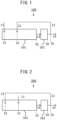
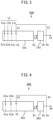
- One aspect of the invention provides a method for producing a resin molded body including a thermoplastic resin (A) and cellulose nanofibers (B).
- the method includes a step of preparing a main supply material (a1) that includes the thermoplastic resin (A) and the cellulose nanofibers (B), and an auxiliary supply material (a2) which is the product of melting treatment of the main supply material (a1), a resin composition-forming step of melt mixing the main supply material (a1) and the auxiliary supply material (a2) to obtain a resin composition (b), and a step of molding the resin composition (b) to obtain a resin molded body.
- Another aspect of the invention provides a method of increasing defibration of cellulose nanofibers (B) during production of a resin molded body that includes a thermoplastic resin (A) and the cellulose nanofibers (B).
- the method includes a step of preparing a main supply material that includes the thermoplastic resin (A) and the cellulose nanofibers (B), and an auxiliary supply material which is the product of melting treatment of the main supply material, a resin composition-forming step of melt mixing the main supply material and the auxiliary supply material to obtain a resin composition that includes two or more types of cellulose nanofibers with different thermal histories, and a step of molding the resin composition to obtain a resin molded body.
- the two or more types of cellulose nanofibers with different thermal histories have different fiber lengths. Since the auxiliary supply material has a more extensive thermal history than the main supply material, according to one aspect the fiber lengths of the cellulose nanofibers in the auxiliary supply material are smaller than the fiber lengths of the cellulose nanofibers in the main supply material.
- the resin molded body is a molten mixture of the constituent components of the main supply material (specifically the thermoplastic resin (A), the cellulose nanofibers (B) and optional additional components), and the auxiliary supply material.
- the resin molded body produced by the first embodiment may typically be provided in the form of pellets.
- the resin molded body is a molten mixture comprising a molten mixture that includes a thermoplastic resin (A), cellulose nanofibers (B) and optional additional components (first material), and a second material having a different composition.
- the first material may be a resin molded body obtained by the first embodiment.
- the resin molded body produced by the second embodiment may typically be provided in the form of pellets, or in various molded product forms.
- the main supply material (a1) may be in the form of a mixture that includes the thermoplastic resin (A), the cellulose nanofibers (B) and optional additional components, and it may have the constituent components of the main supply material (i.e. the thermoplastic resin (A), cellulose nanofibers (B) and optional additional components) prepared separately.
- the auxiliary supply material is the product of melting treatment of the main supply material.
- the auxiliary supply material therefore has substantially the same composition as the main supply material (that is, the types and amounts of the constituent components are the same), but it may also have at least some of the constituent components of the main supply material modified by the melting treatment. Such modification includes reduced fiber lengths of the cellulose nanofibers (B).
- the auxiliary supply material (a2) Since the auxiliary supply material (a2) has essentially the same composition as the main supply material, it mixes very satisfactorily with the supplied materials. Since the fiber lengths of the cellulose nanofibers in the main supply material of the auxiliary supply material are reduced, the cellulose nanofibers derived from the main supply material (having relatively large fiber lengths) and the cellulose nanofibers derived from the auxiliary supply material (having relatively small fiber lengths) become mixed in the mixture of the main supply material and auxiliary supply material.
- Increasing the cellulose nanofiber lengths increases the mechanical strength of the resin molded body while reducing the flow property of the resin composition during production of the resin molded body, tending to result in reduced dispersibility of the cellulose nanofibers in the resin molded body and greater anisotropy of the physical properties (such as thermal expansion coefficient) of the resin molded body (for example, differences in the directions corresponding to the MD direction and TD direction during production of the resin molded body). Since the mechanical strength is significantly affected by the presence of cellulose nanofibers with large fiber lengths, it is notably increased even by using a relatively small amount of cellulose nanofibers with large fiber lengths.
- a resin molded body obtained using a mixture of the main supply material and auxiliary supply material has a satisfactory degree of mechanical strength provided mainly by the presence of cellulose nanofibers with large fiber lengths, but a satisfactory effect of reduced anisotropy of physical properties and increased dispersibility is also obtained by the co-presence of cellulose nanofibers with smaller fiber lengths.
- the resin molded body obtained by the method of the disclosure can thus provide a unique advantage of providing satisfactory mechanical strength, as well as both satisfactory dispersibility and low anisotropy.
- the shear exerted during the melting process for the auxiliary supply material produces crazing at the weakest locations of the structure, and specifically in the cellulose nanofiber aggregates present throughout the structure, which creates a synergistic effect due to thinner cellulose nanofiber aggregates and increased viscosity of the system, making it possible to significantly lower the amount of cellulose nanofiber aggregates that can form in the final molded article.
- the auxiliary supply material may be material that has been removed from a portion of the resin molded body and returned to the process.
- the resin molded body obtained after starting production and until the process conditions stabilize for obtaining the desired resin molded body (2) a resin molded body that has substantially the same composition but exhibits different physical properties from the physical properties of the desired resin molded body, or (3) a resin molded body having substantially the same composition as the desired resin molded body among the resin molded bodies obtained in a transient time period in which the composition is varied, may be used as the auxiliary supply material, within the acceptable ranges from the viewpoint of economy.
- the amounts of the components of the resin molded body are within ranges of +5 mass% to -5 mass%. Specifically, if the content of the cellulose nanofibers (B) is 7.5 mass%, for example, then the range is 7.125 mass% to 7.875 mass%. A range of +5% to -5% is equivalent to variation in the composition that results during periodic addition (refilling) of material to the material supply apparatus of the kneader.
- the amount of cellulose nanofibers (B) in the main supply material is preferably 1 mass% or greater, more preferably 3 mass% or greater and even more preferably 5 mass% or greater, while from the viewpoint of satisfactory moldability and dispersibility, as well as low anisotropy, it is preferably 50 mass% or lower, more preferably 40 mass% or lower and even more preferably 20 mass% or lower.
- the thermoplastic resin (A) has a number-average molecular weight of 5000 or greater.
- the number-average molecular weight for the present disclosure is the value determined based on a chromatogram measured using GPC (gel permeation chromatography), in terms of a GPC standard polymer.
- the GPC standard polymer used may be a polymer that is known to those skilled in the art. Common examples include polystyrene, poly(methyl methacrylate), polyethylene glycol and polyethylene oxide.
- the standard polymer that is used is selected depending on the type of eluent used during GPC measurement.
- methyl polymethacrylate is used when the eluent is hexafluoroisopropanol
- polystyrene is used when it is tetrahydrofuran, chloroform, toluene or 1,2,4-trichlorobenzene
- polyethylene glycol or polyethylene oxide is used for methanol, N,N-dimethylformamide or an aqueous system.
- the thermoplastic resin (A) may be a crystalline resin with a melting point in the range of 100°C to 350°C, or an amorphous resin with a glass transition temperature in the range of 100 to 250°C.
- the thermoplastic resin (A) may be constructed of one or more different polymers, which may be homopolymers or copolymers.
- the melting point of the crystalline resin referred to here is the peak top temperature of the endothermic peak appearing when the temperature is increased from 23°C at a temperature-elevating rate of 10°C/min using a differential scanning calorimeter (DSC).
- DSC differential scanning calorimeter
- the enthalpy of the endothermic peak is preferably 10 J/g or greater and more preferably 20 J/g or greater.
- the sample is heated once to temperature conditions of melting point + 20°C or higher, and after the resin has been melted, it is cooled to 23°C at a temperature-lowering rate of 10°C/min and used as the sample.
- the glass transition temperature of the amorphous resin referred to here is the peak top temperature of the peak with high reduction in storage modulus and maximum loss modulus, during measurement with an applied frequency of 10 Hz while increasing the temperature from 23°C at a temperature-elevating rate of 2°C/min, using a dynamic viscoelasticity measuring apparatus.
- the measuring frequency during this time is preferably at least one or more times in 20 seconds, in order to increase the measuring precision.
- the method of preparing the measuring sample is not particularly restricted, but from the viewpoint of eliminating the effect of molding strain it is preferred to use a strip cut out from a hot press molded article, the size (width or thickness) of the cut out strip preferably being as small as possible, from the viewpoint of heat conduction.
- the thermoplastic resin (A) may be a polyamide-based resin, polyester-based resin, polyacetal-based resin, polycarbonate-based resin, polyacrylic-based resin, polyphenylene ether-based resin (including modified polyphenylene ethers modified by blending or graft polymerization of polyphenylene ether with other resins), polyallylate-based resin, polysulfonebased resin, polyphenylene sulfide-based resin, polyethersulfone-based resin, polyketone-based resin, polyphenylene ether ketone-based resin, polyimide-based resin, polyamideimide-based resin, polyetherimide-based resin, polyurethane-based resin or polyolefin-based resin (such as an ⁇ -olefin (co)polymer), or any of various ionomers.
- thermoplastic resin used may be modified with one or more compounds selected from among unsaturated carboxylic acids and their acid anhydrides or derivatives.
- one or more resins from the group consisting of polyolefin-based resins, polyamide-based resins, polyester-based resins, polyacetal-based resins, polyacrylic-based resins, polyphenylene ether-based resins and polyphenylene sulfide-based resins.
- thermoplastic resin (A) is a polyamide.
- the polyolefin-based resin is a polymer obtained by polymerizing a monomer unit that includes an olefin (such as an ⁇ -olefin).
- polyolefin-based resins include, but are not limited to, ethylene-based (co)polymers such as low-density polyethylene (for example, linear low-density polyethylene), high-density polyethylene, ultralow-density polyethylene and ultrahigh molecular weight polyethylene, polypropylene-based (co)polymers such as polypropylene, ethylene-propylene copolymer and ethylene-propylene-diene copolymer, and copolymers of ⁇ -olefins such as ethylene with other monomer units, including ethyleneacrylic acid copolymer, ethylene-methyl methacrylate copolymer and ethylene-glycidyl methacrylate copolymer.
- the most preferred polyolefin-based resin is polypropylene.
- polypropylene which has a melt mass-flow rate (MFR) of 3 g/10 min to 30 g/10 min, as measured at 230°C with a load of 21.2 N, according to ISO1133.
- MFR melt mass-flow rate
- the lower limit for MFR is more preferably 5 g/10 min, even more preferably 6 g/10 min and most preferably 8 g/10 min.
- the upper limit for MFR is more preferably 25 g/10 min, even more preferably 20 g/10 min and most preferably 18 g/10 min.
- the MFR preferably is not above this upper limit from the viewpoint of increased toughness of the composition, and it is preferably not less than the lower limit from the viewpoint of the flow property of the composition.
- An acid-modified polyolefin-based resin may also be suitably used in order to increase the affinity with cellulose.
- the acid may be appropriately selected from among maleic acid, fumaric acid, succinic acid, phthalic acid and their anhydrides, or polycarboxylic acids such as citric acid. Preferred among these are maleic acid or its anhydride, for an increased modification rate. While the modification method is not particularly restricted, a common method involves heating the resin to above the melting point in the presence or in the absence of a peroxide, for melt kneading.
- the polyolefin resin to be acid-modified may be any of the aforementioned polyolefin-based resins, but polypropylene is most suitable for use.
- the acid-modified polyolefin-based resin may be used alone, but it is preferably used in admixture with a non-modified polyolefin-based resin in order to adjust the modification rate of the composition.
- the proportion of the acid-modified polypropylene is preferably 0.5 mass% to 50 mass% with respect to the total polypropylene.
- the lower limit is more preferably 1 mass%, even more preferably 2 mass%, yet more preferably 3 mass%, even yet more preferably 4 mass% and most preferably 5 mass%.
- the upper limit is more preferably 45 mass%, even more preferably 40 mass%, yet more preferably 35 mass%, even yet more preferably 30 mass% and most preferably 20 mass%.
- the upper limit is more preferably 45 mass%, even more preferably 40 mass%, yet more preferably 35 mass%, even yet more preferably 30 mass% and most preferably 20 mass%.
- the lower limit for the acid modification rate of the acid-modified polyolefin-based resin is preferably 0.01 mass%, more preferably 0.1 mass%, even more preferably 0.3 mass%, especially preferably 0.5 mass% and most preferably 0.7 mass%.
- the upper limit is preferably 10 mass%, more preferably 5 mass%, even more preferably 3 mass%, especially preferably 2 mass% and most preferably 1.5 mass%. In order to maintain interfacial strength with the cellulose it is preferably higher than the lower limit, and in order to maintain the mechanical properties of the acid-modified polyolefin it is preferably lower than the upper limit.
- the melt mass-flow rate (MFR) of the acid-modified polypropylene as measured at 230°C with a load of 21.2 N according to ISO1133 is preferably 50 g/10 min or higher, in order to increase affinity with the cellulose interface.
- a more preferred lower limit is 100 g/10 min, with 150 g/10 min being more preferred and 200 g/10 min being most preferred.
- An MFR within this range will provide an advantage of residing more easily at the interface between the cellulose and the resin.
- thermoplastic resin examples include, but are not limited to, polyamide 6, polyamide 11 and polyamide 12 obtained by polycondensation reaction of lactams, or polyamide 6,6, polyamide 6,10, polyamide 6,11, polyamide 6,12, polyamide 6,T, polyamide 6,1, polyamide 9,T, polyamide 10,T, polyamide 2M5,T, polyamide MXD,6, polyamide 6,C or polyamide 2M5,C obtained as copolymers between diamines such as 1,6-hexanediamine, 2-methyl-1,5-pentanediamine, 1,7-heptanediamine, 2-methyl-1-6-hexanediamine, 1,8-octanediamine, 2-methyl-1,7-heptanediamine, 1,9-nonanediamine, 2-methyl-1,8-octanediamine, 1,10-decanediamine, 1,11-undecanediamine, 1,12-dodecanediamine and m- xylylenediamine, and dicarboxylic acids such as
- polyamide-based resins More preferred among these polyamide-based resins are aliphatic polyamides such as polyamide 6, polyamide 11, polyamide 12, polyamide 6,6, polyamide 6,10, polyamide 6,11 and polyamide 6,12, and alicyclic polyamides such as polyamide 6,C and polyamide 2M5,C.
- terminal carboxyl group concentration of the polyamide-based resin there are no particular restrictions on the terminal carboxyl group concentration of the polyamide-based resin, but the lower limit is preferably 20 ⁇ mol/g and more preferably 30 ⁇ mol/g.
- the upper limit for the terminal carboxyl group concentration is preferably 150 ⁇ mol/g, more preferably 100 ⁇ mol/g and even more preferably 80 ⁇ mol/g.
- the ratio of carboxy-terminal groups with respect to the total terminal groups is more preferably 0.30 to 0.95.
- the lower limit for the carboxy-terminal group ratio is more preferably 0.35, yet more preferably 0.40 and most preferably 0.45.
- the upper limit for the carboxy-terminal group ratio is more preferably 0.90, even more preferably 0.85 and most preferably 0.80.
- the carboxy-terminal group ratio is preferably 0.30 or greater from the viewpoint of dispersibility of the cellulose nanofibers (B) in the resin composition, and it is preferably no greater than 0.95 from the viewpoint of the color tone of the obtained resin composition.
- the method used to adjust the terminal group concentration of the polyamide-based resin may be a publicly known method.
- the method may be addition of a terminal group adjuster that reacts with the terminal groups, such as a diamine compound, monoamine compound, dicarboxylic acid compound, monocarboxylic acid compound, acid anhydride, monoisocyanate, monoacid halide, monoester or monoalcohol, to the polymerization solution, so as to result in the prescribed terminal group concentration during polymerization of the polyamide.
- a terminal group adjuster that reacts with the terminal groups, such as a diamine compound, monoamine compound, dicarboxylic acid compound, monocarboxylic acid compound, acid anhydride, monoisocyanate, monoacid halide, monoester or monoalcohol
- aliphatic monocarboxylic acids such as acetic acid, propionic acid, butyric acid, valeric acid, caproic acid, caprylic acid, lauric acid, tridecanoic acid
- one or more terminal group adjusters selected from the group consisting of acetic acid, propionic acid, butyric acid, valeric acid, caproic acid, caprylic acid, lauric acid, tridecanoic acid, myristic acid, palmitic acid, stearic acid and benzoic acid are preferred, with acetic acid being most preferred.
- aliphatic monoamines such as methylamine, ethylamine, propylamine, butylamine, hexylamine, octylamine, decylamine, stearylamine, dimethylamine, diethylamine, dipropylamine and dibutylamine
- alicyclic monoamines such as cyclohexy
- one or more terminal group adjusters selected from the group consisting of butylamine, hexylamine, octylamine, decylamine, stearylamine, cyclohexylamine and aniline.
- the concentration of the amino terminal groups and carboxy-terminal groups is preferably determined from the integral of the characteristic signal corresponding to each terminal group, according to 1 H-NMR, from the viewpoint of precision and convenience.
- the recommended method for determining the terminal group concentration is, specifically, the method described in Japanese Unexamined Patent Publication HEI No. 7-228775 . When this method is used, heavy trifluoroacetic acid is useful as the measuring solvent.
- the number of scans in 1 H-NMR must be at least 300, even with measurement using a device having sufficient resolving power.
- the terminal group concentration can be measured by a titration method such as described in Japanese Unexamined Patent Publication No. 2003-055549 .
- quantitation is preferably by 1 H-NMR.
- the viscosity number [VN] of the polyamide-based resin measured in 96% sulfuric acid according to ISO307, is preferably 60 to 300, more preferably 70 to 250, even more preferably 75 to 200 and especially preferably 80 to 180.
- the polyamide-based resin with a viscosity number in this range is advantageous in that it provides a satisfactory flow property in the die during injection molding of the resin composition to produce the resin molded body, allowing the resin molded body to have a satisfactory outer appearance.
- Preferred polyester-based resins for the thermoplastic resin are not particularly restricted but include one or more from among polyethylene terephthalate (PET), polybutylene terephthalate (PBT), polyethylene naphthalate (PEN), polybutylene succinate (PBS), polybutylene succinate adipate (PBSA), polybutylene adipate terephthalate (PBAT), polyallylate (PAR), polyhydroxyalkanoic acids (PHA) (polyester resins composed of 3-hydroxyalkanoic acids), polylactic acid (PLA) and polycarbonate (PC).
- Preferred polyester-based resins among these include PET, PBS, PBSA, PBT and PEN, with PBS, PBSA and PBT being more preferred.
- the terminal groups of the polyester-based resin can be freely altered by the monomer ratio during polymerization and by the presence or absence and amount of stabilizer at the ends, and preferably the carboxy-terminal group ratio with respect to the total terminal groups of the polyester-based resin ([COOH]/[total terminal groups]) is 0.30 to 0.95.
- the lower limit for the carboxy-terminal group ratio is more preferably 0.35, yet more preferably 0.40 and most preferably 0.45.
- the lower limit for the carboxy-terminal group ratio is more preferably 0.90, yet more preferably 0.85 and most preferably 0.80.
- the carboxy-terminal group ratio is preferably 0.30 or greater from the viewpoint of dispersibility of the cellulose nanofibers (B) in the composition, and it is preferably no greater than 0.95 from the viewpoint of the color tone of the obtained composition.
- thermoplastic resins preferred as thermoplastic resins are commonly homopolyacetals obtained from formaldehyde starting materials and copolyacetals with trioxane as the main monomer and comprising 1,3-dioxolane, for example, as a comonomer component, and although both of these may be used, copolyacetals are preferably used from the viewpoint of thermal stability during working.
- the amount of comonomer component (for example, 1,3-dioxolane) is more preferably in the range of 0.01 to 4 mol%.
- the preferred lower limit for the comonomer component amount is 0.05 mol%, more preferably 0.1 mol% and even more preferably 0.2 mol%.
- the upper limit is more preferably 3.5 mol%, even more preferably 3.0 mol%, yet more preferably 2.5 mol% and most preferably 2.3 mol%.
- the lower limit is preferably in the range specified above from the viewpoint of thermal stability during extrusion and during molding, and the upper limit is preferably in the range specified above from the viewpoint of mechanical strength.
- the cellulose nanofibers (B) are cellulose with a mean fiber size of 1000 nm or smaller.
- Preferred examples of cellulose nanofibers (B) include, but are not limited to, one or more types from among cellulose nanofibers obtained using cellulose pulp starting materials, and modified forms of such cellulose. From the viewpoint of stability and performance, it is preferable to use one or more types of modified cellulose.
- the mean fiber size of the cellulose nanofibers (B) is 1000 nm or smaller, preferably 500 nm or smaller and more preferably 200 nm or smaller, from the viewpoint of obtaining satisfactory mechanical strength (especially tensile modulus) for the resin molded body.
- the mean fiber size is the value determined to be the equivalent spherical diameter (volume-average particle diameter) of the particles at a cumulative volume of 50% using a laser diffraction/scattering method-based particle size distribution meter.
- the mean fiber size can be measured by the following method.
- the cellulose nanofibers (B) at a solid content of 40 mass% are kneaded for 30 minutes in a planetary mixer (for example, a 5DM-03-R by Shinagawa Machinery Works Co., Ltd., hook-type stirring blade) at 126 rpm, room temperature and ordinary pressure, and then a purified water suspension is prepared to 0.5 mass%, a high-shear homogenizer (for example, an "Excel ED-7 Autohomogenizer", trade name of Nippon Seiki Co., Ltd., processing conditions) is used for dispersion at rotational speed: 15,000 rpm ⁇ 5 minutes, a centrifugal separator (for example, a "Model 6800 Centrifugal Separator", trade name of Kubota Corp., Rotor type Model RA-400) is used for centrifugation under conditions with a centrifugal force of 39,200 m 2 /s for 10 minutes, producing a supernatant, and the
- the supernatant liquid is used to measure the 50% cumulative particle diameter, as the volume-average particle diameter (specifically, the equivalent spherical diameter of particles at a cumulative volume of 50% with respect to the total volume of the particles), in the volume frequency particle size distribution obtained using a laser diffraction/scattering method-based particle size distribution meter (for example, an "LA-910” or "LA-950", trade names of Horiba, Ltd., with ultrasonic treatment for 1 minute, refractive index: 1.20).
- a laser diffraction/scattering method-based particle size distribution meter for example, an "LA-910" or "LA-950", trade names of Horiba, Ltd., with ultrasonic treatment for 1 minute, refractive index: 1.20.
- the LID ratio of the cellulose nanofibers (B) is 20 or greater.
- the lower limit for LID of the cellulose nanofibers is preferably 30, more preferably 40, even more preferably 50 and yet more preferably 100.
- the upper limit is not particularly restricted but is preferably 10,000 or lower from the viewpoint of handleability.
- the LID ratio of the cellulose nanofibers is preferably within this range to exhibit satisfactory mechanical properties for the resin composition of this disclosure using a small amount of cellulose nanofibers.
- the length (L), diameter (D) and LID ratio of the cellulose nanofibers are determined by preparing aqueous dispersions of the cellulose nanofibers, each aqueous dispersion being dispersed using a high-shear homogenizer (for example, an "Excel ED-7 Autohomogenizer", trade name of Nippon Seiki Co., Ltd.), under processing conditions of rotational speed: 15,000 rpm ⁇ 5 minutes, diluting the aqueous dispersion with purified water to 0.1 to 0.5 mass%, casting this onto mica, and using the air-dried product as a measuring sample for measurement with an optical microscope or a high-resolution scanning microscope (SEM) or atomic force microscope (AFM).
- a high-shear homogenizer for example, an "Excel ED-7 Autohomogenizer", trade name of Nippon Seiki Co., Ltd.
- the length (L) and diameter (D) of 100 randomly selected cellulose nanofibers are measured in an observation field with the magnification adjusted so as to observe at least 100 cellulose nanofibers, and the ratio (L/D) is calculated.
- the lengths and diameters of the cellulose nanofibers of the present disclosure are the number-average values for the 100 cellulose fibers.
- the cellulose nanofibers (B) may be cellulose obtained by treating pulp or the like with hot water or the like at 100°C or higher, hydrolyzing the hemicellulose portion to weaken it, and then defibrating by a pulverizing method using a high-pressure homogenizer, microfluidizer, ball mill or disk mill.
- the cellulose nanofibers (B) are modified (i.e. modified cellulose nanofibers).
- the modified cellulose nanofibers (B) may have the cellulose modified with one or more modifying agents selected from among esterifying agents, silylating agents, isocyanate compounds, halogenated alkylating agents, alkylene oxides and/or glycidyl compounds.
- the cellulose nanofibers (B) are unmodified, or are modified by lacking oxoacid-modified groups (i.e. sites where the hydroxyl groups of the cellulose are converted with oxoacids (such as carboxylic acids) or their salts (such as carboxylic acid salts)), preferred examples of modified forms being forms modified with the modifying agents mentioned above.
- An esterifying agent used as a modifying agent includes any organic compound having at least one functional group capable of reacting with the hydroxyl groups on the surfaces of the cellulose nanofibers (B) to esterify them.
- the esterification can be carried out by the method described in paragraph [0108] of International Patent Publication No. 2017/159823 .
- the esterifying agent may be a commercially available reagent or product.
- esterifying agents are not particularly restricted and include aliphatic monocarboxylic acids such as acetic acid, propionic acid, butyric acid, valeric acid, caproic acid, caprylic acid, lauric acid, tridecanoic acid, myristic acid, palmitic acid, stearic acid, pivalic acid and isobutyric acid; alicyclic monocarboxylic acids such as cyclohexanecarboxylic acid; aromatic monocarboxylic acids such as benzoic acid, toluic acid, o-naphthalenecarboxylic acid, ⁇ -naphthalenecarboxylic acid, methylnaphthalenecarboxylic acid and phenylacetic acid; and any optionally selected mixtures of the same, as well as acid and vinyl alcohol ester compounds (such as vinyl acetate, vinyl propionate, vinyl butyrate, vinyl valerate, vinyl caproate, vinyl caprylate and vinyl laurate) and, selected from among the acids mentioned
- acetic acid Preferred for use among these from the viewpoint of reactivity, stability and cost are acetic acid, propionic acid, butyric acid, valeric acid, caproic acid, caprylic acid, lauric acid, tridecanoic acid, myristic acid, palmitic acid and stearic acid, esters of these acids with vinyl alcohol, and benzoic acid, acetic anhydride, maleic anhydride, succinic anhydride and phthalic anhydride.
- a silylating agent used as a modifying agent may be any Si-containing compound having at least one reactive group that can react with the hydroxyl groups on the surface of the cellulose, or groups remaining after their hydrolysis.
- the silylating agent may be a commercially available reagent or product.
- silylating agents include, but are not limited to, chlorodimethylisopropylsilane, chlorodimethylbutylsilane, chlorodimethyloctylsilane, chlorodimethyldodecylsilane, chlorodimethyloctadecylsilane, chlorodimethylphenylsilane, chloro(1-hexenyl)dimethylsilane, dichlorohexylmethylsilane, dichloroheptylmethylsilane, trichlorooctylsilane, hexamethyldisilazane, 1,3-divinyl-1,1,3,3-tetramethyldisilazane, 1,3-divinyl-1,3-diphenyl-1,3-dimethyl-disilazane, 1,3-N-dioctyltetramethyl-disilazane, diisobutylte
- Preferred for use among these from the viewpoint of reactivity, stability and cost are hexamethyldisilazane, octadecyldimethylmethoxysilane, dimethyloctylmethoxysilane and trimethylethoxysilane.
- a halogenated alkylating agent used as a modifying agent includes any organic compound having at least one functional group capable of reacting with the hydroxyl groups on the surfaces of cellulose to form alkyl halides.
- the halogenated alkylating agent used may be a commercially available reagent or product.
- halogenated alkylating agents are not particularly restricted and include chloropropane, chlorobutane, bromopropane, bromohexane, bromoheptane, iodomethane, iodoethane, iodooctane, iodooctadecane and iodobenzene.
- Preferred for use among these from the viewpoint of reactivity, stability and cost are bromohexane and iodooctane.
- An isocyanate compound used as a modifying agent may be any organic compound having at least one isocyanate group capable of reacting with the hydroxyl groups on the surfaces of the cellulose nanofibers (B).
- the isocyanate compound may be a blocked isocyanate compound that allows the blocking groups to dissociate at a specific temperature to regenerate isocyanate groups, or a polyisocyanate dimer or trimer, or a modified isocyanate biuret or polymethylene polyphenyl polyisocyanate (polymeric MDI). They may be commercially available reagents or products.
- isocyanate compounds include, but are not limited to, aliphatic polyisocyanates, alicyclic polyisocyanates, aromatic polyisocyanates, aromatic-aliphatic polyisocyanates and blocked isocyanate compounds and polyisocyanates.
- Examples include tetramethylene diisocyanate, dodecamethylene diisocyanate, hexamethylene diisocyanate, 2,2,4-trimethylhexamethylene diisocyanate, 2,4,4-trimethylhexamethylene diisocyanate, lysine diisocyanate, 2-methylpentane-1,5-diisocyanate, 3-methylpentane-1,5-diisocyanate, isophorone diisocyanate, hydrogenated xylylene diisocyanate, 4,4'-dicyclohexylmethane diisocyanate, 1,4-cyclohexane diisocyanate, methylcyclohexylene diisocyanate, 1,3-bis(isocyanatomethyl)cyclohexane), tolylene diisocyanate (TDI), 2,2'-diphenylmethane diisocyanate, 2,4'-diphenylmethane diisocyanate, 4,4'-diphen
- TDI TDI
- MDI hexamethylene diisocyanate
- blocked isocyanates obtained using hexamethylene diisocyanate-modified compounds and hexamethylene diisocyanate as starting materials.
- the dissociation temperature of the blocking groups of these blocked isocyanate compounds is at maximum preferably 210°C, more preferably 190°C and even more preferably 150°C, from the viewpoint of reactivity and stability.
- the minimum is preferably 70°C, more preferably 80°C and even more preferably 110°C.
- Blocking agents with blocking group dissociation temperatures in this range include methyl ethyl ketone oxime, ortho-secondary butylphenol, caprolactam, sodium bisulfite, 3,5-dimethylpyrazole and 2-methylimidazole.
- An alkylene oxide and/or glycidyl compound used as a modifying agent may be any organic compound having at least one alkylene oxide, glycidyl and/or epoxy group capable of reacting with the hydroxyl groups on the surface of cellulose.
- the alkylene oxide and/or glycidyl compound may be a commercially available reagent or product.
- alkylene oxide and/or glycidyl compounds include, but are not limited to, glycidyl ethers such as methyl glycidyl ether, ethyl glycidyl ether, butyl glycidyl ether, 2-ethylhexyl glycidyl ether, 2-methyloctyl glycidyl ether, phenyl glycidyl ether, p-tertiary butylphenyl glycidyl ether, sec-butylphenyl glycidyl ether, n-butylphenyl glycidyl ether, phenylphenol glycidyl ether, cresyl glycidyl ether and dibromocresyl glycidyl ether; glycidyl esters such as glycidyl acetate and glycidyl stearate; and poly
- Preferred for use among these from the viewpoint of reactivity, stability and cost are 2-methyloctyl glycidyl ether, hexamethyleneglycol diglycidyl ether and pentaerythritol tetraglycidyl ether.
- the total degree of substitution of the modified cellulose nanofibers is 0.5 or greater, 0.7 or greater or 0.75 or greater from the viewpoint of obtaining satisfactory dispersibility of the cellulose nanofibers (B) in the thermoplastic resin (A), and 1.5 or lower, 1.3 or lower or 1.25 or lower from the viewpoint of satisfactorily maintaining the physical properties of the cellulose nanofibers (B).
- the modified cellulose nanofibers are esterified cellulose nanofibers, and the total degree of substitution is the total degree of ester substitution.
- the degree of substitution can be determined, after freeze-shattering the modified cellulose nanofibers and subjecting them to 13 C solid NMR measurement, using the following formula representing the area intensity (Inf) of the signal attributed to one carbon atom of the modifying group, with respect to the total area intensity (Inp) of the signals attributed to C1-C6 carbons of the pyranose rings of cellulose, appearing in the range of 50 ppm to 110 ppm.
- Degree of substitution Inf ⁇ 6 / Inp
- the signal at 23 ppm attributed to -CH 3 may be used.
- the conditions in the 13 C solid NMR measurement may be as follows, for example.
- the main supply material may also include optional additional components in addition to the thermoplastic resin (A) and cellulose nanofibers (B).
- additional components include surface treatment agents, antioxidants, inorganic fillers and lubricant oils.
- Each of the components may be used alone, or in combinations of two or more. They may also be either commercially available reagents or products.
- Preferred examples for the surface treatment agent include compounds having a hydrophilic segment and a hydrophobic segment in the molecule, and more specifically copolymers obtained using one or more from among compounds that provide hydrophilic segments (for example, polyethylene glycol) and compounds that provide hydrophobic segments (for example, polypropylene glycol, poly(tetramethylene ether) glycol (PTMEG) and polybutadienediol) (for example, block copolymers of propylene oxide and ethylene oxide or block copolymers of tetrahydrofuran and ethylene oxide).
- hydrophilic segments for example, polyethylene glycol
- PTMEG poly(tetramethylene ether) glycol
- PTMEG poly(tetramethylene ether) glycol
- polybutadienediol for example, block copolymers of propylene oxide and ethylene oxide or block copolymers of tetrahydrofuran and ethylene oxide
- the content of the surface treatment agent in the main supply material is preferably 0.1 mass% or greater, or 0.2 mass% or greater, or 0.5 mass%, while from the viewpoint of inhibiting plasticization of the resin molded body to maintain satisfactory strength, it is preferably 50 mass% or lower, or 30 mass%, 20 mass%, 18 mass%, 15 mass%, 10 mass% or 5 mass%.
- the amount of the surface treatment agent with respect to 100 parts by mass of the cellulose nanofibers (B) is preferably 0.1 parts by mass or greater, 0.5 parts by mass or greater or 1 parts by mass or greater, while from the viewpoint of inhibiting plasticization of the resin molded body and maintaining satisfactory strength it is preferably 100 parts by mass or lower, 99 parts by mass or lower, 90 parts by mass or lower, 80 parts by mass or lower, 70 parts by mass or lower, 50 parts by mass or lower or 40 parts by mass or lower.
- the antioxidant is preferably a hindered phenol-based antioxidant, sulfur-based antioxidant or phosphorus-based antioxidant, more preferably a phosphorus-based antioxidant or hindered phenol-based antioxidant, and even more preferably a combination of a phosphorus-based antioxidant and/or hindered phenol-based antioxidant with a hindered amine-based light stabilizer (HALS).
- HALS hindered amine-based light stabilizer
- the amount of antioxidant with respect to the total resin molded body is preferably 0.01 mass% or greater, 0.02 mass% or greater, 0.03 mass% or greater or 0.05 mass% or greater, and preferably 5 mass% or lower, 4 mass% or lower, 3 mass% or lower, 2 mass% or lower or 1 mass% or lower.
- the inorganic filler may be filamentous particles, plate-shaped particles or an inorganic pigment.
- Filamentous particles and plate-shaped particles may have a mean aspect ratio of 5 or greater. Specifically, they may be glass fibers, glass flakes, glass balloons, carbon fibers, carbon nanotubes, carbon black, talc, mica, wollastonite, calcium carbonate, barium sulfate, magnesium hydroxide, magnesium oxide, tobamolite, halloysite, halloysite nanotubes, titanium dioxide, zinc sulfide, zinc oxide, iron oxide or iron sulfide.
- the amount of inorganic filler in the resin molded body is preferably 0.002 parts by mass to 50 parts by mass with respect to 100 parts by mass of the thermoplastic resin (A).
- the lubricant oil may be a natural oil (engine oil, cylinder oil or the like), a synthetic hydrogen carbide (paraffinic oil, naphthene-based oil, aroma oil or the like), or a silicone-based oil.
- the molecular weight of the lubricant oil may be 100 or greater, 400 or greater or 500 or greater, for example, and 5,000,000 or lower, 2,000,000 or lower or 1,000,000 or lower, for example.
- the melting point of the lubricant oil may be -50°C or higher, -30°C or higher or -20°C or higher, for example, and 50°C or lower, 30°C or lower or 20°C or lower, for example.
- the melting point is a temperature 2.5°C lower than the pour point of the lubricant oil, which can be measured according to JIS K2269.
- the content of the lubricant oil with respect to 100 parts by mass of the thermoplastic resin (A) is preferably 0.1 parts by mass or greater, 0.2 parts by mass or greater or 0.3 parts by mass or greater, while from the viewpoint of avoiding unwanted softening of the resin molded body, it is preferably 5.0 parts by mass or lower, 4.5 parts by mass or lower or 4.2 parts by mass or lower.
- the total amount of additional components in the main supply material may be 0.5 mass% or greater or 2 mass% or greater, for example, and 20 mass% or lower, 15 mass% or lower or 20 mass% or lower, for example.
- the main supply material includes 70 mass% to 99 mass% of the thermoplastic resin (A), 1 mass% to 30 mass% of the cellulose nanofibers (B) and 0 mass% to 20 mass% of additional components.
- the main supply material includes 80 mass% to 95 mass% of the thermoplastic resin (A), 5 mass% to 20 mass% of the cellulose nanofibers (B) and 1 mass% to 15 mass% of additional components, or 85 mass% to 95 mass% of the thermoplastic resin (A), 5 mass% to 15 mass% of the cellulose nanofibers (B) and 2 mass% to 10 mass% of additional components.
- the melt mixing is carried out with the blending ratio of the auxiliary supply material at 5 to 50 mass%, with respect to 100 mass% as the total of the main supply material (a1) and auxiliary supply material (a2).
- the blending ratio of the auxiliary supply material is preferably 10 mass% or greater, 15 mass% or greater or 20 mass% or greater, while from the viewpoint of satisfactorily obtaining an effect of increasing the mechanical strength by the cellulose nanofibers (B) of the main supply material, it is preferably 45 mass% or lower, 40 mass% or lower or 25 mass% or lower,
- the mass ratio of the main supply material (a1) and the mass ratio of the auxiliary supply material (a2) in the resin composition (b) may satisfy the relationship represented by the following formula: Mass ratio of auxiliary supply material a2 ⁇ Mass ratio of main supply material a1 . That is, the auxiliary supply material may be present at 50 mass% or greater in the resin composition. The mass ratio of the auxiliary supply material in the resin composition may be 55 mass% or greater, 60 mass% or greater or 70 mass% or greater. The mass ratio of the auxiliary supply material is less than 100 mass%, and is preferably 90 mass% or lower or 80 mass% or lower.
- Figs. 1 to 3 are diagrams showing processes 100, 200, 300 as examples of the method for producing a resin molded body according to the first embodiment.
- the main supply material 11 or its constituent components i.e. the thermoplastic resin (A) 11a, the cellulose nanofibers (B) 11b and the optional additional component 11c), and the auxiliary supply material 12 are melt mixed in a melt mixer 101 to produce a melt-mixed resin composition 13, and the resin composition 13 is molded in a molding unit 102 to produce a resin molded body 14.
- the resin molded body 14 may be in the form of pellets, for example.
- the main supply material 11 may be in the form of a mixture that includes the thermoplastic resin (A) 11a, the cellulose nanofibers (B) 11b and optional additional components 11c (the main supply material 11 in Figs. 1 and 2 ), or in a form with the thermoplastic resin (A) 11a, cellulose nanofibers (B) 11b and optional additional components 11c separately prepared as constituent components of the main supply material 11 (the main supply material 11 in Fig. 3 ). In the latter case, the constituent components of the main supply material become mixed together, and also with the auxiliary supply material, within the melt mixing system.
- the auxiliary supply material 12 is the product of melting treatment of the main supply material 11.
- the auxiliary supply material 12 may be obtained by melting treatment of the main supply material 11 alone, or it may be a recovered portion of the resin molded body 14. In the latter case, as shown in Figs. 1 to 3 , the main supply material 11 and auxiliary supply material 12 are melt mixed and then molded, and a portion of the obtained resin molded body 14 is separated at a separating site S5 and returned back to the melt mixer 101 as auxiliary supply material 12, while the remainder is collected as the target resin molded body 14.
- the auxiliary supply material 12 returned to the melt mixer 101 is melt mixed with freshly supplied main supply material 11.
- the auxiliary supply material 12 is based on the main supply material 11, but is a mixture of multiple compositions that have been subjected to melting treatment a different number of times (that is, having a different thermal history).
- the main supply material 11 and auxiliary supply material 12 are supplied to the melt mixer 101 and melt mixed together.
- the melt mixing is melt kneading.
- the melt mixer 101 may be the mixing unit of a mixer such as a single-screw extruder, twin-screw extruder, roll or Banbury mixer, for example.
- a twin-screw extruder is a preferred type of mixer, and more specifically it may be a twin-screw extruder equipped with a pressure-reducing device and side feeder equipment.
- the LID of the twin-screw extruder may be 30 to 100, 35 to 75 or 45 to 70, for example.
- the means for supplying the main supply material 11 and auxiliary supply material 12 may be any of the following.
- the temperature and time for melt mixing may be set as appropriate for the desired resin molded body.
- the preferred conditions from the viewpoint of obtaining a satisfactory effect of improving the physical properties with the auxiliary supply material (in particular, both satisfactory mechanical strength and low anisotropy), are a temperature in the range from the melt start temperature of the thermoplastic resin (A) to the melt start temperature + 100°C, or from the melt start temperature + 10°C to the melt start temperature + 90°C, or from the melt start temperature + 20°C to the melt start temperature + 85°C, where the "melt start temperature” is the melting point in the case of a crystalline resin, or the temperature at which it begins to easily flow, in the case of an amorphous resin.
- the measuring temperature for the melt mass-flow rate may be the measuring temperature for the melt mass-flow rate.
- the time is 0.1 minute to 3 minutes, 0.2 minute to 2.5 minutes or 0.3 minute to 2.0 minutes.
- the pressure during melt mixing may be set according to the purpose, but a preferred example is a pressure of -0.1 MPa to 10 MPa, -0.15 MPa to 8 MPa or -0.2 MPa to 5 MPa.
- the resin composition 13 is sent to the molding unit 102 from a mixing completion site S3 of the melt mixer 101, and molded by the molding unit 102 into the target shape (a molded article such as pellets, a sheet, a film, or a three-dimensional structure), after which the target resin molded body 14 is extracted from a delivery site S4.
- the melt mixing is melt kneading, and the melt kneading and molding are carried out in a single kneader (for example, the one described under ⁇ Resin composition-forming step>).
- the molding is carried out in a molding machine different from the machine for melt kneading (for example, an injection molding machine).
- the method according to one aspect further includes returning a portion of the resin molded body 14 to the resin composition-forming step as at least part of the auxiliary supply material.
- the resin molded body includes cellulose nanofibers that have passed through melting treatment of the main supply material and at least two resin composition-forming steps.
- the proportion of cellulose nanofibers that have passed through melting treatment of the main supply material and at least two resin composition-forming steps is preferably 20 mass% or lower, 15 mass% or lower or 10 mass% or lower, with respect to 100 mass% as the total amount of the cellulose nanofibers in the resin molded body.
- the cellulose nanofibers include lignin
- the cellulose nanofibers preferably do not have an excessive thermal history from the viewpoint of satisfactorily avoiding coloration and odor (odor due to the decomposing components).
- a proportion in the range specified above is advantageous for avoiding coloration and odor.
- the proportion may also be 1 mass% or greater, 2 mass% or greater or 5 mass% or greater, from the viewpoint of avoiding coloration and odor, while also avoiding increased production cost of the resin molded body.
- the form of the resin molded body according to the first embodiment may be pellets, sheetlike, fibrous, plate-like, rod-like or tubular, but pellets are preferred for easier post-treatment and transport.
- the shapes of the pellets may differ depending on the manner of cutting at the time of extrusion, and may be round, elliptical or cylindrical, for example.
- pellets cut by "underwater cutting” are usually round
- pellets cut by "hot cutting” are usually round or elliptical
- pellets cut by "strand cutting” are usually cylindrical.
- the pellet diameters for round pellets may be 1 mm to 3 mm.
- the pellet diameters may be 1 mm to 3 mm, for example, with pellet lengths of 2 mm to 10 mm, for example.
- the pellet sizes are preferably above these specified lower limits from the viewpoint of operational stability during extrusion, and they are preferably lower than the specified upper limits from the viewpoint of seizing in the molding machine in post-working.
- Fig. 4 is a diagram showing a process 400 as an example of the method for producing a resin molded body according to a second embodiment of the invention.
- the resin composition 43 is produced as a molten mixture obtained by melt mixing the main supply material 41 and auxiliary supply material 42 in the melt mixer 401, and the resin composition 43 is molded in a molding unit 402 to produce a resin molded body 44.
- the resin molded body 44 may be in a form suitable for supply to subsequent steps (such as pellets), or in the form of a product as described below.
- the main supply material 41 may include a first material 41a and a second material 41b.
- the first material 41a is a molten mixture.
- the first material 41a may be a resin molded body 14 obtained by the first embodiment.
- the first material 41a is a molded article containing 100 parts by mass of the thermoplastic resin (A) and 1 to 50 parts by mass of the cellulose nanofibers (B).
- the auxiliary supply material 42 is the product of melting treatment of the main supply material 41.
- the auxiliary supply material 42 may be obtained by melting treatment of the main supply material 41 alone, or it may be a recovered portion of the resin molded body 44. In the latter case, as shown in Fig. 4 , the main supply material 41 and auxiliary supply material 42 are melt mixed and then molded, and a portion of the obtained resin molded body 44 is separated and returned back to the melt mixer 401 as auxiliary supply material 42, while the remainder is collected as the target resin molded body 44.
- the auxiliary supply material 42 returned to the melt mixer 401 is melt mixed with freshly supplied main supply material 41.
- the auxiliary supply material 42 is based on the main supply material 41, but is a mixture of multiple compositions that have been subjected to melting treatment a different number of times (that is, having a different thermal history).
- the melt mixing is melt kneading.
- the melt mixer 401 may be the same as the melt mixer 101 for the first embodiment.
- the melt mixer 401 may be the mixing unit of a mixer such as a single-screw extruder, twin-screw extruder, roll or Banbury mixer, for example.
- a twin-screw extruder is a preferred mixer, and more specifically it may be a twin-screw extruder equipped with a pressure-reducing device and side feeder equipment.
- the LID of the twin-screw extruder may be 30 to 100, 35 to 75 or 45 to 70, for example.
- the means for supplying the main supply material 41 and auxiliary supply material 42 may be any of the following.
- the first material 41a and second material 41b are each supplied to different main supply material-loading sites S1a, S1b of the melt mixer 401, while the auxiliary supply material 42 is loaded into the auxiliary supply material-loading site S2 of the melt mixer 401, and both are melt mixed to produce a resin composition 43.
- the manner in which the first material 41a and second material 41b are supplied may be designed according to the purpose, and they may be supplied to the melt mixer 401 separately or in pre-mixed form.
- FIG. 4 shows an example of supplying the first material 41a, second material 41b and auxiliary supply material 42 in that order from the upstream end of the melt mixer 401, but the order of supply is not limited to this and may be set as appropriate for the purpose.
- the positional relationship between the main supply material-loading site S 1 and the auxiliary supply material-loading site S2 may also be set as appropriate.
- the temperature and time for melt mixing may be set as appropriate for the desired resin molded body.
- the preferred conditions from the viewpoint of obtaining a satisfactory effect of improving the physical properties with the auxiliary supply material (in particular, both satisfactory mechanical strength and low anisotropy), are a temperature from the melt start temperature of the thermoplastic resin (A) to the melt start temperature + 100°C, or from the melt start temperature + 10°C to the melt start temperature + 90°C, or from the melt start temperature + 20°C to the melt start temperature + 85°C, where the "melt start temperature” is the melting point in the case of a crystalline resin, or the temperature at which it begins to easily flow, in the case of an amorphous resin.
- the measuring temperature for the melt mass-flow rate may be the measuring temperature for the melt mass-flow rate.
- the time is 0.1 minute to 3 minutes, 0.2 minute to 2.5 minutes or 0.3 minute to 2.0 minutes.
- the pressure during melt mixing may be set according to the purpose, but a preferred example is a pressure of 0.01 MPa to 10 MPa, 0.02 MPa to 8 MPa or 0.03 MPa to 5 MPa.
- the relationship between the elastic modulus of the main supply material (a1) and the elastic modulus of the resin composition (b) is preferably [elastic modulus of resin composition (b)] ⁇ [elastic modulus of main supply material (a1) ⁇ 0.99], or [elastic modulus of resin composition (b)] ⁇ [elastic modulus of main supply material (a1) ⁇ 1.00], or [elastic modulus of resin composition (b)] ⁇ [elastic modulus of main supply material (a1) ⁇ 1.05], or [elastic modulus of resin composition (b)] ⁇ [elastic modulus of main supply material (a1) ⁇ 1.10].
- Such a resin composition (b) is advantageous because it yields a resin molded body with an excellent elastic modulus. From the viewpoint of easy production of the resin composition (b), it may be [elastic modulus of resin composition (b)] ⁇ [elastic modulus of main supply material (a1) ⁇ 1.50], or [elastic modulus of resin composition (b)] ⁇ [elastic modulus of main supply material (a1) ⁇ 1.40], or [elastic modulus of resin composition (b)] ⁇ [elastic modulus of main supply material (a1) ⁇ 1.30].
- the elastic modulus referred to here is a value obtained by the same measuring method, and it may be the flexural modulus or tensile modulus.
- the resin composition 43 is sent to the molding unit 402 from a mixing completion site S3 of the melt mixer 401, and molded by the molding unit 402 into the target shape, after which the target resin molded body 44 is extracted from a delivery site S4.
- the molding unit 402 may be constructed for molding in a manner selected from among extrusion molding, injection molding, vacuum forming, blow molding, injection compression molding, decorative molding, mixed material molding, gas assisted injection molding, foam injection molding, low-pressure molding, ultrathin injection molding (ultra high-speed injection molding) and in-mold composite molding (insert molding or outsert molding), for example.
- the melt mixing is melt kneading, and the melt kneading and molding are carried out in a single kneader (for example, the one described under ⁇ Resin composition-forming step>).
- a portion of the resin molded body 44 is returned to the melt mixer 401 from the auxiliary supply material-loading site S2, with the remainder being recovered as product. That is, the method according to one aspect further includes returning a portion of the resin molded body 44 to the resin composition-forming step as at least part of the auxiliary supply material.
- the proportion of cellulose nanofibers that have passed through at least two resin composition-forming steps is preferably 20 mass% or lower, 15 mass% or lower or 10 mass% or lower, and may be 1 mass% or greater, 2 mass% or greater or 5 mass% or greater, for example, with respect to 100 mass% as the total amount of the cellulose nanofibers in the resin molded body.
- the form of the resin molded body according to the second embodiment may be any of various molded product forms, in addition to those mentioned for the first embodiment.
- Such products include, but are not limited to, mechanism components such as cams, sliders, levers, arms, clutches, felt clutches, idler gears, pulleys, rollers, soft rollers, key stems, key tops, shutters, reels, shafts, joints, axes, bearings and guides; outsert molding resin parts, insert molding resin parts, office automation equipment members such as chassis, trays, side plates, printers and copying machines; camera or video equipment parts such as VTRs (Video tape recorder), video movies, digital video cameras, cameras and digital cameras; cassette players, optical disk drives such as DAT, LD (Laser disk), MD (Mini disk), CD (Compact disk) [including CD-ROM (Read only memory), CD-R (Recordable) and CD-RW (Rewritable)], DVD (Digital versatile disk) [including DVD-ROM, DVD-R
- the molded article of this embodiment may be an automobile part, which term includes fuel related parts such as gasoline tanks, fuel pump modules, valves and gasoline tank flanges; doorrelated parts such as door locks, door handles, window regulators and speaker grills; seat belt peripheral parts such as seat belt slip rings and press buttons, parts such as combination switch parts, switches and clips; mechanical parts for extracting and inserting mechanical pencil pen tips or mechanical pencil cores; opening and closing mechanical parts for wash basins, drainage ports and drain plugs; automatic vending machine opening and closing lock mechanisms and product discharge mechanical parts; clothing cord stoppers, adjustors and buttons; watering nozzles and watering hose connecting joints; construction parts such as stair railings and flooring material supports; disposable cameras, toys, fasteners, chains, conveyors, buckles, sports goods, automatic vending machines, furniture, musical instruments, industrial machinery parts (for example, electromagnetic device housings, roll materials, transport arms and medical equipment members), general machine parts, automobile/railway/vehicle parts (for example, outer platings, chassis, aerodynamic members, seats and internal
- a resin molded body produced by the method of the disclosure has the fiber lengths of the cellulose nanofibers (B) controlled in a special manner, so that both satisfactory mechanical strength and low anisotropy are obtained.
- the TD/MD ratio for the molding shrinkage of the resin molded body may be 1.01 to 3.0, 1.01 to 1.75, 1.01 to 1.6 or 1.01 to 1.4.
- the molding shrinkage is the value measured by the method of ISO294-4.
- the molding for this purpose is carried out under conditions according to the ISO standards referred to in regard to the molding method for the resin that is used.
- the MD direction and TD direction are, respectively, the MD direction and TD direction during molding of the resin molded body.
- the TD/MD ratio of the molding shrinkage is preferably within this range because anisotropy of the resin molded body will be reduced.
- the tensile strength of the resin molded body is 90 MPa or greater, 95 MPa or greater, 100 MPa or greater or 110 MPa or greater.
- the tensile strength preferably satisfies this condition because the mechanical strength of the resin molded body will be higher.
- the tensile strength is the value measured by the method of ISO527.
- the suitable molding conditions are the same as described for the molding shrinkage.
- the tensile strength may be 300 MPa or lower, 280 MPa or lower or 250 MPa or lower, for balance with the other properties of the resin molded body (such as toughness).
- both the TD/MD ratio and the tensile strength of the resin molded body are within the specified ranges.
- the molding shrinkage of the resin molded body in the MD direction is preferably 0.1% or greater, 0.2% or greater or 0.3% or greater, and preferably 1.2% or lower, 1.0% or lower or 0.7% or lower.
- the molding shrinkage of the resin molded body in the TD direction is preferably 0.4% or greater or 0.5% or greater, and preferably 1.2% or lower, 1.0% or lower or 0.9% or lower.
- the sum of the molding shrinkage in the MD direction and the molding shrinkage in the TD direction may be 0.5% to 2.6%, 0.5% to 1.9%, 0.6% to 1.6% or 0.8% to 1.5%.
- the resin molded body preferably [Rb] ⁇ [Ra1], [Rb] ⁇ [Ra1 ⁇ 0.95], [Rb] ⁇ [Ra1 ⁇ 0.90] or [Rb] ⁇ [Ra1 ⁇ 0.85], where Rb is the TD/MD ratio of the molding shrinkage of the resin molded body and Ra1 is the TD/MD ratio of the molding shrinkage of the comparison resin molded body using only the main supply material.
- Rb is the TD/MD ratio of the molding shrinkage of the resin molded body
- Ra1 is the TD/MD ratio of the molding shrinkage of the comparison resin molded body using only the main supply material.
- Ra1 and Rb may be [Rb] > [Ra1 ⁇ 0.50], [Rb] > [Ra1 ⁇ 0.60] or [Rb] > [Ra1 ⁇ 0.70], for example, from the viewpoint of ease of production of the resin molded body.
- the linear expansion coefficient (in the MD direction) of the resin molded body in a temperature range of 0°C to 60°C is preferably 60 ppm/K or lower, 50 ppm/K or lower, 45 ppm/K or lower or 35 ppm/K or lower.
- the lower limit for the linear expansion coefficient is not particularly restricted, but from the viewpoint of easier production it is preferably 5 ppm/K or higher and more preferably 10 ppm/K or higher, for example.
- the linear expansion coefficient is the value measured according to ISO11359-2.
- the difference between the value of the yellowness index (YI) of the resin molded body and the value of the yellowness index (YI) of the auxiliary supply material may be 10 or less, 8 or less or 7 or less.
- the value of the yellowness index (YI) is the value measured by the method of JIS K7373.
- An injection molding machine was used for molding of a multipurpose test piece conforming to ISO294-1, from the obtained molded article in the form of pellets.
- the tensile yield strength of the obtained multipurpose test piece was measured according to ISO527-1. The maximum strength was used instead for molded pieces that tore before reaching the yield point.
- the obtained molded article in the form of pellets was molded into 60 mm ⁇ 60 mm ⁇ 2 mm and 60 mm ⁇ 80 mm ⁇ 2 mm flat plates using an injection molding machine, according to JIS K7152-3.
- a 60 mm ⁇ 60 mm ⁇ 2 mm flat plate was used for Examples 1 to 21 and Comparative Examples 1 to 5, and a 60 mm ⁇ 80 mm ⁇ 2 mm flat plate was used for Example 22 and Comparative Examples 6 and 7.
- the dimensions of the flat molded piece were accurately measured in the resin flow direction (MD) and the direction perpendicular to the flow direction (TD), according to ISO294-4, and the shrinkage factor was calculated.
- the shrinkage factor in the TD direction was divided by the shrinkage factor in the MD direction to calculate the mold shrinkage ratio.
- the flat plate molded for measurement of the mold shrinkage was used for measurement of the yellowness index according to JIS K7373.
- the difference between the value of the yellowness index (YI) of the obtained resin molded body compared to the value of the yellowness index (YI) of the auxiliary supply material during this time was calculated as the change in yellowness index ( ⁇ YI).
- the obtained molded article in the form of pellets was molded into a flat plate with a width of 50 mm, a length of 70 mm and a thickness of 1 mm, and having a 1-mm diameter pinpoint gate.
- the die temperature during this time was adjusted to 25°C.
- the gate side was pressed against the surface and the gap between the molded piece and smooth surface on the opposite side was measured.
- the gap was measured by capturing it in a photograph. Measurement was conducted for at least five flat plates, and the value for warping was calculated as the average of 3 points excluding the maximum and minimum.
- the obtained molded article in the form of pellets was cut with a microtome in the direction perpendicular to the flow, and the smooth surface was shaved and photographed using an optical microscope (BX53M: product of Olympus Corp.). The molded pellets were photographed at three points. The obtained photographs were binarized using an image analyzer and the total number with a circle equivalent diameter of 5 ⁇ m or larger was calculated.
- the rotational speed of the bead mill during circulation was 2500 rpm, and the circumferential speed was 12 m/s.
- the beads used were zirconia, ⁇ 2.0 mm, and the fill factor was 70% (with a slit gap of 0.6 mm in the bead mill).
- the slurry temperature was controlled to 40°C with a chiller, for absorption of the heat release by abrasion.
- the diameter was 65 nm and the LID was approximately 450.
- the mixture was circulated to obtain an acetylated CNF slurry.
- the circulation conditions were the same as in the defibrating step.
- the circulating operation time was 30 minutes, 60 minutes or 120 minutes, to obtain acetylated CNF slurries with different degrees of substitution.
- the degree of substitution of each CNF obtained under the different conditions was measured to be 0.50 for the one with a circulation time of 30 minutes, 1.02 for the one with a circulation time of 60 minutes and 1.49 for the one with a circulation time of 120 minutes.
- the defibrated CNF wet cake and each acetylated CNF wet cake was adjusted in concentration with purified water to a cellulose solid concentration of 10 mass%, and then 5 parts by mass of PEG 20,000 was added to 100 parts by mass of CNF, the mixture was thoroughly stirred, and a revolving/rotating stirrer (V-mini300k by EME Co.) was used for vacuum drying at about 40°C to obtain different CNF dry powders.
- a material-feeding throat (hereunder referred to simply as "throat") was provided for "barrel 1", as the barrel furthest upstream in the extruder, side feeding apparatuses for feeding of the starting materials were provided for barrel 4 and barrel 7 (the side feed to barrel 4 will hereunder be referred to simply as “side 1” and the side feed to barrel 7 as “side 2”), and a volatilizing decompression port was provided for barrel 14.
- a die with two 3 mm-diameter spinnerets was set at the front end of the extruder, allowing extrusion of the molten resin into the form of a strand.
- the molten strand was cooled in a water tank provided after the melt mixer, and then cut into pellets using a pelletizer to obtain resin molded body pellets. Some of the obtained resin molded body pellets were used as an auxiliary supply material. (The auxiliary supply material form will hereunder be referred to as "pellets").
- the obtained resin molded body pellets were also molded using an injection molding machine (TR05EH2 by Sodick Plustech Co., Ltd., 5 ton locking pressure), with an FPC connector (length: 30 mm, width: 1 mm, 2 impressions, 50 pinholes, pinhole pitch: 0.5 millimeter pitch) die at an injection speed of 300 mm/sec, to obtain a connector-type resin molded body.
- the connector-type molded article was pulverized using a pulverizer and adjusted to a diameter of ⁇ 5 mm using a mesh to obtain a pulverized auxiliary supply material. (This auxiliary supply material form will hereunder be referred to as "pulverized product").
- Melt mixing was carried out with the barrel temperature of the melt mixer set to 150°C for barrels 1 to 3 and 250°C for barrels 4 to 15 and the die, and with supply from the throat section at 60 mass% of PA6 and 40 mass% of CNF having a degree of substitution of 1.02, to obtain high-concentration PA/CNF pellets (hereunder referred to simply as "PA/CNFMB").
- the rotational speed of the screw of the melt mixer was 300 rpm, and the throughput was 18 kg/hr.
- melt mixing was carried out in the same manner as Preparation Example 2, except that the melt mixer barrel temperature was set to 100°C for barrels 1 to 3 and to 200°C for barrels 4 to 15 and the die, and PA6 was changed to PP, to obtain high-concentration PP/CNF pellets (hereunder referred to simply as "PP/CNF-MB").
- the main supply material was supplied from the main supply material addition location, with the barrel temperature of the melt mixer set to 150°C for barrels 1 to 3, to 260°C for barrels 4 to 7 and to 250°C for barrels 8 to 15 and the die, and with the compositions listed in Table 1 and Table 2 for the main supply material, while the auxiliary supply material, as a molten mixture of the main supply material, was supplied from the auxiliary supply material addition location, and they were melt mixed to obtain resin molded body pellets which were evaluated for different properties as shown in Tables 1 and 2.
- the rotational speed of the screw of the melt mixer was 300 rpm, and the throughput was 25 kg/hr.
- the pellets of Comparative Example 1 were used for the auxiliary supply material in Examples 1 to 11 (auxiliary supply material 12 in the process flow).
- the pellets of Comparative Example 3 were used for the auxiliary supply material in Example 12 (auxiliary supply material 12 in the process flow), and the pellets of Comparative Example 5 were used as the auxiliary supply material in Example 13.
- the pulverized product of the auxiliary supply material used in Example 6 was obtained by molding the obtained resin molded body pellets into a connector-type resin molded body and then pulverizing it.
- the main supply material of Example 9 was PA6 supplied from the throat section and CNF supplied from the side 1.
- Comparative Examples 1, 3 and 5 were Examples where no auxiliary supply material was added. Comparative Examples 2, 4, 6 and 7 are Examples without the main supply material, i.e. with the auxiliary supply material alone, and they correspond to 100% recirculation (recycling).
- Example 16 Main supply material composition PA6 mass% 80 80 70 70 70 70 70 CNF mass% 20 20 20 30 30 30 30 CNF degree of substitution - 1.02 1.02 1.02 1.02 1.02 0 0.5 1.49 Main supply material mass% 100 90 0 100 90 90 90 90 Auxiliary supply material mass% 0 10 100 0 10 10 10 10 Process 100 100 100 100 100 100 100 100 100 100 Main supply material addition location Throat Throat Throat Throat Throat Throat Throat Throat Throat Secondary supply material addition location -- Throat Throat -- Throat Throat Throat Throat Throat Auxiliary supply material form --- -- Pellets Pellets -- Pellets Pellets Pellets Pellets Pellets Pellets Pellets Pellets Tensile strength MPa 88 125 91 94 136 86 115 98 Molding shrinkage (MD) % 0.08 0.28 0.41 0.05 0.21 0.18 0.22 0.25 Molding shrinkage (MD
- Example 10 Example 10
- the barrel temperature of the melt mixer was set to 100°C for barrels 1 to 3, to 200°C for barrels 4 to 7 and to 190°C for barrels 8 to 15 and the die and the composition and conditions were changed as shown in Table 3, and the properties were evaluated. The results are listed in Table 3.
- Example 21 Main supply material composition PP mass% 60 60 60 60 60 60 PP/CNFMB mass% 40 40 40 40 40 40 CNF degree of substitution - 1.02 1.02 1.02 1.02 0.5 Main supply material mass% 95 90 75 50 75 Auxiliary supply material mass% 5 10 25 50 25
- Example 6 Example 6
- Comparative Example 7 was treated twice by the process 100.
- the method for producing a resin molded body according to the present invention can be suitably applied for production of resin molded bodies to be used for purposes that require satisfactory mechanical strength and low anisotropy of physical properties.
Landscapes
- Chemical & Material Sciences (AREA)
- Engineering & Computer Science (AREA)
- Mechanical Engineering (AREA)
- Medicinal Chemistry (AREA)
- Polymers & Plastics (AREA)
- Organic Chemistry (AREA)
- Health & Medical Sciences (AREA)
- Chemical Kinetics & Catalysis (AREA)
- Manufacturing & Machinery (AREA)
- Environmental & Geological Engineering (AREA)
- Life Sciences & Earth Sciences (AREA)
- Biochemistry (AREA)
- Materials Engineering (AREA)
- Compositions Of Macromolecular Compounds (AREA)
- Processes Of Treating Macromolecular Substances (AREA)
Claims (17)
- Procédé destiné à produire un corps moulé en résine qui comporte une résine thermoplastique (A) et des nanofibres de cellulose (B), le procédé comportant :une étape de préparation d'un matériau d'alimentation principal (a1) qui comporte la résine thermoplastique (A) et les nanofibres de cellulose (B), et d'un matériau d'alimentation auxiliaire (a2) qui est le produit d'un traitement de fusion du matériau d'alimentation principal (a1), etune étape de formation de composition de résine consistant à mélanger à l'état fondu le matériau d'alimentation principal (a1) et le matériau d'alimentation auxiliaire (a2) pour obtenir une composition de résine (b), etune étape de moulage de la composition de résine (b) pour obtenir un corps moulé en résine,dans lequel le mélange à l'état fondu est réalisé avec la proportion de mélange du matériau d'alimentation auxiliaire (a2) à 5 à 50 % en masse, rapporté à 100 % en masse comme total du matériau d'alimentation principal (a1) et du matériau d'alimentation auxiliaire (a2) ; oudans lequel le rapport TD/MD pour le retrait au moulage du corps moulé en résine est de 1,05 à 3,0, le rapport TD/MD pour le retrait au moulage étant mesuré comme spécifié dans la description.
- Procédé destiné à augmenter le défibrage de nanofibres de cellulose (B) pendant la production d'un corps moulé en résine qui comporte une résine thermoplastique (A) et des nanofibres de cellulose (B), le procédé comportant :une étape de préparation d'un matériau d'alimentation principal (a1) qui comporte la résine thermoplastique (A) et les nanofibres de cellulose (B), et d'un matériau d'alimentation auxiliaire (a2) qui est le produit d'un traitement de fusion du matériau d'alimentation principal (a1), etune étape de formation de composition de résine consistant à mélanger à l'état fondu le matériau d'alimentation principal (a1) et le matériau d'alimentation auxiliaire (a2) pour obtenir une composition de résine (b) qui comporte au moins deux types de nanofibres de cellulose avec différentes histoires thermiques, etune étape de moulage de la composition de résine (b) pour obtenir un corps moulé en résine,dans lequel le mélange à l'état fondu est réalisé avec la proportion de mélange du matériau d'alimentation auxiliaire (a2) à 5 à 50 % en masse, rapporté à 100 % en masse comme total du matériau d'alimentation principal (a1) et du matériau d'alimentation auxiliaire (a2) ; oudans lequel le rapport TD/MD pour le retrait au moulage du corps moulé en résine est de 1,05 à 3,0, le rapport TD/MD pour le retrait au moulage étant mesuré comme spécifié dans la description.
- Procédé selon la revendication 2, dans lequel les au moins deux types de nanofibres de cellulose avec différentes histoires thermiques ont différentes longueurs de fibre.
- Procédé selon l'une quelconque des revendications 1 à 3, dans lequel une portion du corps moulé en résine est utilisée comme le matériau d'alimentation auxiliaire (a2).
- Procédé selon l'une quelconque des revendications 1 à 4, dans lequel le matériau d'alimentation principal (a1) comporte la résine thermoplastique (A) à 100 parties en masse et les nanofibres de cellulose (B) à 1 à 50 parties en masse.
- Procédé selon l'une quelconque des revendications 1 à 5, dans lequel les composants constitutifs du matériau d'alimentation principal (a1) sont mélangés ensemble et avec le matériau d'alimentation auxiliaire (a2) dans un système de mélange à l'état fondu.
- Procédé selon l'une quelconque des revendications 1 à 6, dans lequel le matériau d'alimentation principal (a1) est une combinaison d'un premier matériau sous la forme d'un article moulé qui comporte la résine thermoplastique (A) à 100 parties en masse et les nanofibres de cellulose (B) à 1 à 50 parties en masse, et d'un deuxième matériau avec une composition différente de celle du premier matériau.
- Procédé selon l'une quelconque des revendications 1 à 7, dans lequel le mélange à l'état fondu est un malaxage à l'état fondu.
- Procédé selon l'une quelconque des revendications 1 à 8, dans lequel le corps moulé en résine se présente sous la forme de granulés.
- Procédé selon la revendication 9, dans lequel le mélange à l'état fondu est un malaxage à l'état fondu, et le malaxage à l'état fondu et le moulage sont réalisés dans un seul malaxeur.
- Procédé selon l'une quelconque des revendications 1 à 10, dans lequel, dans le corps moulé en résine, le retrait au moulage dans la direction MD est de 0,2 % à 1,2 % et le retrait au moulage dans la direction TD est de 0,5 % à 1,2 %, le retrait au moulage MD ou TD étant mesuré comme spécifié dans la description.
- Procédé selon l'une quelconque des revendications 1 à 11, dans lequel le corps moulé en résine a une résistance à la traction de 90 MPa ou plus, la résistance à la traction étant mesurée comme spécifié dans la description.
- Procédé selon l'une quelconque des revendications 1 à 12, le procédé comportant en outre le retour d'une portion du corps moulé en résine à l'étape de formation de composition de résine comme au moins une partie du matériau d'alimentation auxiliaire (a2), de telle sorte que le corps moulé en résine comporte des nanofibres de cellulose qui sont passées par un traitement de fusion du matériau d'alimentation principal (a1) et au moins deux étapes de formation de composition de résine, et
le pourcentage des nanofibres de cellulose qui sont passées par un traitement de fusion du matériau d'alimentation principal (a1) et au moins deux étapes de formation de composition de résine est de 20 % en masse ou moins, rapporté à 100 % en masse comme quantité totale des nanofibres de cellulose dans le corps moulé en résine. - Procédé selon l'une quelconque des revendications 1 à 13, dans lequel la différence entre la valeur de l'indice de jaunissement (YI) du corps moulé en résine et la valeur de l'indice de jaunissement (YI) du matériau d'alimentation auxiliaire est de 10 ou moins, l'indice de jaunissement étant mesuré comme spécifié dans la description.
- Procédé selon l'une quelconque des revendications 1 à 14, dans lequel la résine thermoplastique (A) est un polyamide.
- Procédé selon l'une quelconque des revendications 1 à 15, dans lequel les nanofibres de cellulose (B) sont des nanofibres de cellulose modifiée.
- Procédé selon la revendication 16, dans lequel le degré de substitution des nanofibres de cellulose modifiée est de 0,5 à 1,5.
Applications Claiming Priority (2)
| Application Number | Priority Date | Filing Date | Title |
|---|---|---|---|
| JP2019099379A JP6752935B1 (ja) | 2019-05-28 | 2019-05-28 | 樹脂成形体の製造方法 |
| PCT/JP2020/020962 WO2020241707A1 (fr) | 2019-05-28 | 2020-05-27 | Procédé de production de corps moulé en résine |
Publications (4)
| Publication Number | Publication Date |
|---|---|
| EP3978551A1 EP3978551A1 (fr) | 2022-04-06 |
| EP3978551A4 EP3978551A4 (fr) | 2022-07-27 |
| EP3978551B1 true EP3978551B1 (fr) | 2023-08-16 |
| EP3978551C0 EP3978551C0 (fr) | 2023-08-16 |
Family
ID=72333556
Family Applications (1)
| Application Number | Title | Priority Date | Filing Date |
|---|---|---|---|
| EP20814095.4A Active EP3978551B1 (fr) | 2019-05-28 | 2020-05-27 | Procédé de production d'un corps moulé en resine et procédé permettant d'augmenter la defibration des nanofibres de cellulose pendant la production du corps moule en resine |
Country Status (5)
| Country | Link |
|---|---|
| US (1) | US11572447B2 (fr) |
| EP (1) | EP3978551B1 (fr) |
| JP (1) | JP6752935B1 (fr) |
| CN (1) | CN113811576A (fr) |
| WO (1) | WO2020241707A1 (fr) |
Families Citing this family (4)
| Publication number | Priority date | Publication date | Assignee | Title |
|---|---|---|---|---|
| CA3145718A1 (fr) * | 2021-01-15 | 2022-07-15 | Innotech Alberta Inc. | Couche de demoulant comportant des particules de cellulose |
| JPWO2023286757A1 (fr) * | 2021-07-14 | 2023-01-19 | ||
| JP7322989B1 (ja) | 2022-02-07 | 2023-08-08 | 大日本印刷株式会社 | 化粧シートおよびその製造方法、ならびに、樹脂層およびその製造方法 |
| CN115417931B (zh) * | 2022-09-22 | 2024-03-22 | 上海同化益生纤生物科技有限公司 | 一种耐温型纤维素的制备方法与应用 |
Family Cites Families (23)
| Publication number | Priority date | Publication date | Assignee | Title |
|---|---|---|---|---|
| JPH07228775A (ja) | 1994-02-17 | 1995-08-29 | Kuraray Co Ltd | 難燃性ポリアミド組成物 |
| JP3156749B2 (ja) | 1995-08-24 | 2001-04-16 | カルソニックカンセイ株式会社 | ポリアミドのリサイクル性評価方法及びポリアミドのリサイクル方法 |
| JP2003055549A (ja) | 2001-06-05 | 2003-02-26 | Kuraray Co Ltd | ポリアミド組成物 |
| JP2004195890A (ja) * | 2002-12-20 | 2004-07-15 | Toray Ind Inc | 繊維強化熱可塑性樹脂成形品 |
| JP5489788B2 (ja) | 2010-03-05 | 2014-05-14 | オリンパス株式会社 | 鏡枠用樹脂構造体 |
| WO2011126038A1 (fr) | 2010-04-06 | 2011-10-13 | ユニチカ株式会社 | Composition de résine polyamide et procédé de production d'une composition de résine polyamide |
| JP5563905B2 (ja) * | 2010-06-25 | 2014-07-30 | 積水化学工業株式会社 | リサイクル樹脂含有ポリエチレン系樹脂組成物を押出成形してなるパイプ成形品、及びポリエチレン系樹脂リサイクル方法 |
| US20120241352A1 (en) * | 2011-03-22 | 2012-09-27 | Pramanik Pranabes K | Articles formed from a multi-layer sheet structure |
| JP2012201767A (ja) | 2011-03-24 | 2012-10-22 | Nissan Motor Co Ltd | 樹脂組成物 |
| JP2012251039A (ja) * | 2011-06-01 | 2012-12-20 | Asahi Kasei Chemicals Corp | リサイクル樹脂組成物およびその製造方法 |
| CN105960315B (zh) | 2014-02-03 | 2017-07-28 | 东丽株式会社 | 纤维增强多层颗粒、将其成型而成的成型品、及纤维增强多层颗粒的制造方法 |
| US20160168363A1 (en) | 2014-06-27 | 2016-06-16 | Api Intellectual Property Holdings, Llc | Nanocellulose-polymer composites, and processes for producing them |
| JP6697839B2 (ja) | 2014-07-03 | 2020-05-27 | ユニチカ株式会社 | シート状成形体 |
| ES2699023T3 (es) * | 2014-12-22 | 2019-02-06 | Borealis Ag | Composición basada en polietileno reciclado a partir de desechos de cable |
| JP6091589B2 (ja) * | 2015-03-19 | 2017-03-08 | 国立大学法人京都大学 | 化学修飾セルロースナノファイバー及び熱可塑性樹脂を含有する繊維強化樹脂組成物 |
| WO2017141779A1 (fr) | 2016-02-18 | 2017-08-24 | スターライト工業株式会社 | Dispersion de nanofibres, procédé de production d'une dispersion de nanofibres, nanofibres pulvérulentes obtenues à partir de la dispersion, composition de résine comprenant lesdites nanofibres pulvérulentes, et matériau de moulage pour imprimante 3d dans laquelle ladite composition de résine est utilisée |
| US11566118B2 (en) | 2016-02-18 | 2023-01-31 | Starlite Co., Ltd. | Nanofiber dispersion, method of producing nanofiber dispersion, powdery nanofibers obtainable from the dispersion, resin composition containing the powdery nanofibers ad molding material for 3D printer using the resin composition |
| RU2703245C1 (ru) | 2016-03-16 | 2019-10-15 | Асахи Касеи Кабусики Кайся | Тонкое целлюлозное волокно и способ его получения |
| JP6860137B2 (ja) | 2016-07-29 | 2021-04-14 | 日本製紙株式会社 | 繊維性成形品製造用の成形材料およびそれを用いた成形品 |
| JP6469068B2 (ja) | 2016-12-12 | 2019-02-13 | 富士紙管株式会社 | 繊維成分混入合成樹脂組成物及びその製造方法 |
| WO2018235905A1 (fr) | 2017-06-22 | 2018-12-27 | 国立大学法人京都大学 | Composition de résine renforcée par des fibres, corps moulé renforcé par des fibres, et procédé de fabrication de celle-ci |
| CN117417635A (zh) * | 2019-05-13 | 2024-01-19 | 旭化成株式会社 | 低孔隙的粒料以及成型体的制造方法 |
| JP2020193345A (ja) | 2020-08-19 | 2020-12-03 | 旭化成株式会社 | 樹脂成形体の製造方法 |
-
2019
- 2019-05-28 JP JP2019099379A patent/JP6752935B1/ja active Active
-
2020
- 2020-05-27 CN CN202080035183.4A patent/CN113811576A/zh active Pending
- 2020-05-27 US US17/613,198 patent/US11572447B2/en active Active
- 2020-05-27 EP EP20814095.4A patent/EP3978551B1/fr active Active
- 2020-05-27 WO PCT/JP2020/020962 patent/WO2020241707A1/fr unknown
Non-Patent Citations (1)
| Title |
|---|
| 2018, Retrieved from the Internet <URL:https://www.env.go.jp/earth/ondanka/cnfl.html> [retrieved on 20230110] * |
Also Published As
| Publication number | Publication date |
|---|---|
| WO2020241707A1 (fr) | 2020-12-03 |
| EP3978551A4 (fr) | 2022-07-27 |
| US20220315714A1 (en) | 2022-10-06 |
| JP2020193266A (ja) | 2020-12-03 |
| EP3978551A1 (fr) | 2022-04-06 |
| US11572447B2 (en) | 2023-02-07 |
| JP6752935B1 (ja) | 2020-09-09 |
| CN113811576A (zh) | 2021-12-17 |
| EP3978551C0 (fr) | 2023-08-16 |
Similar Documents
| Publication | Publication Date | Title |
|---|---|---|
| EP3978551B1 (fr) | Procédé de production d'un corps moulé en resine et procédé permettant d'augmenter la defibration des nanofibres de cellulose pendant la production du corps moule en resine | |
| JP7117181B2 (ja) | セルロース含有樹脂組成物 | |
| EP3786215B1 (fr) | Dispersion aqueuse contenant des nanofibres de cellulose et composition de résine contenant des nanofibres de cellulose | |
| US20230160457A1 (en) | Cellulose-containing gear | |
| US20240309208A1 (en) | Highly Heat-Resistant Resin Composite Including Chemically Modified, Fine Cellulose Fibers | |
| JP7114376B2 (ja) | セルロース含有樹脂組成物 | |
| JP2024032925A (ja) | 樹脂成形体の製造方法 | |
| WO2020050286A1 (fr) | Particules composites et composition de résine | |
| JP7561086B2 (ja) | 低空孔のペレット、及び成形体の製造方法 | |
| JP2020063408A (ja) | 分散液及びセルロース含有組成物 | |
| JP7152558B2 (ja) | ポリアミド樹脂組成物 | |
| JP7266995B2 (ja) | セルロースナノファイバー組成物 | |
| JP2020176157A (ja) | セルロース組成物 | |
| JP2020007493A (ja) | セルロース含有樹脂組成物 | |
| JP2020015242A (ja) | セルロース含有樹脂組成物 | |
| Tuna et al. | Effect of coupling agent on polylactic acid/polypropylene and polylactic acid/polyamide 6 foam composites | |
| JP2024106126A (ja) | 樹脂組成物及び成形品 | |
| Hazliza Aida et al. | 2 Fabrication Process of Bio-Composites Filament for Fused Deposition Modeling | |
| JP2024070251A (ja) | ポリアセタール樹脂組成物及びその製造方法 | |
| Michael et al. | Mechanical properties of polyamide 11 reinforced with cellulose nanofibres from Triodia pungens | |
| JP2020122165A (ja) | ポリアミド樹脂組成物 |
Legal Events
| Date | Code | Title | Description |
|---|---|---|---|
| STAA | Information on the status of an ep patent application or granted ep patent |
Free format text: STATUS: THE INTERNATIONAL PUBLICATION HAS BEEN MADE |
|
| PUAI | Public reference made under article 153(3) epc to a published international application that has entered the european phase |
Free format text: ORIGINAL CODE: 0009012 |
|
| STAA | Information on the status of an ep patent application or granted ep patent |
Free format text: STATUS: REQUEST FOR EXAMINATION WAS MADE |
|
| 17P | Request for examination filed |
Effective date: 20211215 |
|
| AK | Designated contracting states |
Kind code of ref document: A1 Designated state(s): AL AT BE BG CH CY CZ DE DK EE ES FI FR GB GR HR HU IE IS IT LI LT LU LV MC MK MT NL NO PL PT RO RS SE SI SK SM TR |
|
| STAA | Information on the status of an ep patent application or granted ep patent |
Free format text: STATUS: EXAMINATION IS IN PROGRESS |
|
| A4 | Supplementary search report drawn up and despatched |
Effective date: 20220624 |
|
| RIC1 | Information provided on ipc code assigned before grant |
Ipc: B29B 17/00 20060101ALI20220620BHEP Ipc: B29B 7/92 20060101ALI20220620BHEP Ipc: B29B 7/82 20060101ALI20220620BHEP Ipc: B29B 7/72 20060101ALI20220620BHEP Ipc: B29B 7/60 20060101ALI20220620BHEP Ipc: B29B 7/48 20060101ALI20220620BHEP Ipc: C08J 3/20 20060101AFI20220620BHEP |
|
| 17Q | First examination report despatched |
Effective date: 20220707 |
|
| DAV | Request for validation of the european patent (deleted) | ||
| DAX | Request for extension of the european patent (deleted) | ||
| TPAC | Observations filed by third parties |
Free format text: ORIGINAL CODE: EPIDOSNTIPA |
|
| TPAC | Observations filed by third parties |
Free format text: ORIGINAL CODE: EPIDOSNTIPA |
|
| RIC1 | Information provided on ipc code assigned before grant |
Ipc: C08L 77/02 19740701ALI20230109BHEP Ipc: C08B 3/20 19680901ALI20230109BHEP Ipc: B29B 17/00 19850101ALI20230109BHEP Ipc: B29B 7/90 19850101ALI20230109BHEP Ipc: B29B 7/82 19850101ALI20230109BHEP Ipc: B29B 7/72 19850101ALI20230109BHEP Ipc: B29B 7/60 19850101ALI20230109BHEP Ipc: C08J 3/20 19740701AFI20230109BHEP |
|
| GRAP | Despatch of communication of intention to grant a patent |
Free format text: ORIGINAL CODE: EPIDOSNIGR1 |
|
| STAA | Information on the status of an ep patent application or granted ep patent |
Free format text: STATUS: GRANT OF PATENT IS INTENDED |
|
| INTG | Intention to grant announced |
Effective date: 20230309 |
|
| GRAS | Grant fee paid |
Free format text: ORIGINAL CODE: EPIDOSNIGR3 |
|
| GRAA | (expected) grant |
Free format text: ORIGINAL CODE: 0009210 |
|
| STAA | Information on the status of an ep patent application or granted ep patent |
Free format text: STATUS: THE PATENT HAS BEEN GRANTED |
|
| AK | Designated contracting states |
Kind code of ref document: B1 Designated state(s): AL AT BE BG CH CY CZ DE DK EE ES FI FR GB GR HR HU IE IS IT LI LT LU LV MC MK MT NL NO PL PT RO RS SE SI SK SM TR |
|
| REG | Reference to a national code |
Ref country code: CH Ref legal event code: EP |
|
| REG | Reference to a national code |
Ref country code: DE Ref legal event code: R096 Ref document number: 602020015961 Country of ref document: DE |
|
| REG | Reference to a national code |
Ref country code: IE Ref legal event code: FG4D |
|
| U01 | Request for unitary effect filed |
Effective date: 20230911 |
|
| U07 | Unitary effect registered |
Designated state(s): AT BE BG DE DK EE FI FR IT LT LU LV MT NL PT SE SI Effective date: 20230915 |
|
| PG25 | Lapsed in a contracting state [announced via postgrant information from national office to epo] |
Ref country code: GR Free format text: LAPSE BECAUSE OF FAILURE TO SUBMIT A TRANSLATION OF THE DESCRIPTION OR TO PAY THE FEE WITHIN THE PRESCRIBED TIME-LIMIT Effective date: 20231117 |
|
| PG25 | Lapsed in a contracting state [announced via postgrant information from national office to epo] |
Ref country code: IS Free format text: LAPSE BECAUSE OF FAILURE TO SUBMIT A TRANSLATION OF THE DESCRIPTION OR TO PAY THE FEE WITHIN THE PRESCRIBED TIME-LIMIT Effective date: 20231216 |
|
| PG25 | Lapsed in a contracting state [announced via postgrant information from national office to epo] |
Ref country code: RS Free format text: LAPSE BECAUSE OF FAILURE TO SUBMIT A TRANSLATION OF THE DESCRIPTION OR TO PAY THE FEE WITHIN THE PRESCRIBED TIME-LIMIT Effective date: 20230816 Ref country code: NO Free format text: LAPSE BECAUSE OF FAILURE TO SUBMIT A TRANSLATION OF THE DESCRIPTION OR TO PAY THE FEE WITHIN THE PRESCRIBED TIME-LIMIT Effective date: 20231116 Ref country code: IS Free format text: LAPSE BECAUSE OF FAILURE TO SUBMIT A TRANSLATION OF THE DESCRIPTION OR TO PAY THE FEE WITHIN THE PRESCRIBED TIME-LIMIT Effective date: 20231216 Ref country code: HR Free format text: LAPSE BECAUSE OF FAILURE TO SUBMIT A TRANSLATION OF THE DESCRIPTION OR TO PAY THE FEE WITHIN THE PRESCRIBED TIME-LIMIT Effective date: 20230816 Ref country code: GR Free format text: LAPSE BECAUSE OF FAILURE TO SUBMIT A TRANSLATION OF THE DESCRIPTION OR TO PAY THE FEE WITHIN THE PRESCRIBED TIME-LIMIT Effective date: 20231117 |
|
| PG25 | Lapsed in a contracting state [announced via postgrant information from national office to epo] |
Ref country code: PL Free format text: LAPSE BECAUSE OF FAILURE TO SUBMIT A TRANSLATION OF THE DESCRIPTION OR TO PAY THE FEE WITHIN THE PRESCRIBED TIME-LIMIT Effective date: 20230816 |
|
| PG25 | Lapsed in a contracting state [announced via postgrant information from national office to epo] |
Ref country code: ES Free format text: LAPSE BECAUSE OF FAILURE TO SUBMIT A TRANSLATION OF THE DESCRIPTION OR TO PAY THE FEE WITHIN THE PRESCRIBED TIME-LIMIT Effective date: 20230816 |
|
| PG25 | Lapsed in a contracting state [announced via postgrant information from national office to epo] |
Ref country code: SM Free format text: LAPSE BECAUSE OF FAILURE TO SUBMIT A TRANSLATION OF THE DESCRIPTION OR TO PAY THE FEE WITHIN THE PRESCRIBED TIME-LIMIT Effective date: 20230816 Ref country code: RO Free format text: LAPSE BECAUSE OF FAILURE TO SUBMIT A TRANSLATION OF THE DESCRIPTION OR TO PAY THE FEE WITHIN THE PRESCRIBED TIME-LIMIT Effective date: 20230816 Ref country code: ES Free format text: LAPSE BECAUSE OF FAILURE TO SUBMIT A TRANSLATION OF THE DESCRIPTION OR TO PAY THE FEE WITHIN THE PRESCRIBED TIME-LIMIT Effective date: 20230816 Ref country code: CZ Free format text: LAPSE BECAUSE OF FAILURE TO SUBMIT A TRANSLATION OF THE DESCRIPTION OR TO PAY THE FEE WITHIN THE PRESCRIBED TIME-LIMIT Effective date: 20230816 Ref country code: SK Free format text: LAPSE BECAUSE OF FAILURE TO SUBMIT A TRANSLATION OF THE DESCRIPTION OR TO PAY THE FEE WITHIN THE PRESCRIBED TIME-LIMIT Effective date: 20230816 |
|
| U20 | Renewal fee paid [unitary effect] |
Year of fee payment: 5 Effective date: 20240408 |
|
| REG | Reference to a national code |
Ref country code: DE Ref legal event code: R097 Ref document number: 602020015961 Country of ref document: DE |
|
| 26N | No opposition filed |
Effective date: 20240517 |