EP3976510B1 - Verfahren zum transferieren von artikeln der keramikverarbeitenden industrie - Google Patents
Verfahren zum transferieren von artikeln der keramikverarbeitenden industrie Download PDFInfo
- Publication number
- EP3976510B1 EP3976510B1 EP20736418.3A EP20736418A EP3976510B1 EP 3976510 B1 EP3976510 B1 EP 3976510B1 EP 20736418 A EP20736418 A EP 20736418A EP 3976510 B1 EP3976510 B1 EP 3976510B1
- Authority
- EP
- European Patent Office
- Prior art keywords
- article
- support
- end edge
- articles
- recesses
- Prior art date
- Legal status (The legal status is an assumption and is not a legal conclusion. Google has not performed a legal analysis and makes no representation as to the accuracy of the status listed.)
- Active
Links
Images


Classifications
-
- B—PERFORMING OPERATIONS; TRANSPORTING
- B65—CONVEYING; PACKING; STORING; HANDLING THIN OR FILAMENTARY MATERIAL
- B65G—TRANSPORT OR STORAGE DEVICES, e.g. CONVEYORS FOR LOADING OR TIPPING, SHOP CONVEYOR SYSTEMS OR PNEUMATIC TUBE CONVEYORS
- B65G59/00—De-stacking of articles
- B65G59/005—De-stacking of articles by using insertions or spacers between the stacked layers
-
- B—PERFORMING OPERATIONS; TRANSPORTING
- B65—CONVEYING; PACKING; STORING; HANDLING THIN OR FILAMENTARY MATERIAL
- B65G—TRANSPORT OR STORAGE DEVICES, e.g. CONVEYORS FOR LOADING OR TIPPING, SHOP CONVEYOR SYSTEMS OR PNEUMATIC TUBE CONVEYORS
- B65G60/00—Simultaneously or alternatively stacking and de-stacking of articles
-
- B—PERFORMING OPERATIONS; TRANSPORTING
- B65—CONVEYING; PACKING; STORING; HANDLING THIN OR FILAMENTARY MATERIAL
- B65G—TRANSPORT OR STORAGE DEVICES, e.g. CONVEYORS FOR LOADING OR TIPPING, SHOP CONVEYOR SYSTEMS OR PNEUMATIC TUBE CONVEYORS
- B65G61/00—Use of pick-up or transfer devices or of manipulators for stacking or de-stacking articles not otherwise provided for
Definitions
- the present invention relates to a method for transferring articles of the ceramic processing industry.
- the horizontal grippers have the drawback of requiring a sufficient free space around the articles to be withdrawn in order to operate correctly. This problem is particularly felt when the articles to be withdrawn are part of a group of articles arranged close to and/or in contact with one another.
- DE4407392A1 , JPH0781752 , EP0377400 , FR2814161 , DE3442333 , DE3207890 , EP0525564 , DE2342782 disclose several different systems for moving objects of various types between positions.
- DE4407392A1 discloses the features of the preamble of claim 1.
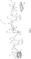
- the number 1 indicates as a whole a system for transferring articles 2 of the ceramic processing industry from an input station 3 to an output station 4.
- the article 2 comprises (is) at least a substantially flat product of the ceramic processing industry (namely a slab - e.g. a tile) .
- the substantially flat product is made of ceramic.
- the articles 2 are boxes (more precisely, each box encloses one or more substantially flat articles - slabs) and the transfer system 1 is configured to transfer the boxes individually or in groups.
- Each article 2 is delimited by a respective peripheral edge PB (see, in particular, figure 9 ) and has two major faces FC opposite each other.
- the two major faces FC are delimited by the peripheral edge PB (and are substantially parallel to each other).
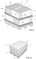
- the system 1 comprises a support 5 (better illustrated in figures 2-5 ), which is configured to support a group G of articles 2, more precisely a group of boxes.
- the support 5 is configured to support the articles 2 (and/or the boxes) arranged (on their edges) vertically (as illustrated in figure 9; figure 10 , on the other hand, illustrates boxes - and, therefore, the articles 2 - arranged horizontally) .
- the articles 2 (and/or the boxes) arranged vertically (namely standing - in an erect manner) rest on at least one portion of their peripheral edge PB; whereas the articles 2 (and/or the boxes) arranged horizontally rest on one of their major faces FC.
- the articles 2 are arranged in the group G so that at least a lateral portion (at least one side LPB) of the peripheral edge PB of an article 2 is (completely) covered (and therefore is not accessible, for example, to a gripper jaw for the transfer of articles) by one or more other articles 2 of the group G.
- at least a lateral portion (at least one side LPB) of the peripheral edge PB of an article 2 is in contact with at least a further article 2 (namely directly or, for example, with the interposition of the walls of the relative boxes).
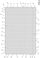
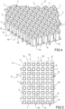
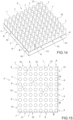
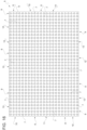
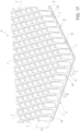
- the support 5 (better illustrated in figures 2-5 ), in turn, comprises a base portion 6 and a plurality of projections 7, which protrude from the base portion 6.
- the projections 7 are arranged on the base portion 6 so as to define rows 8.
- the projections 7 are arranged on the base portion 6 so as to define also transverse rows 9 (more precisely, substantially perpendicular) to the rows 8.
- the projections 7 are configured to support the articles 2.
- the support 5 further comprises a plurality of recesses 10, each of which extends from an end edge 11 of the support 5 and is arranged between the projections 7.
- Each recess 10 is (at least partially) delimited by the projections 7.
- each recess 10 extends (at least partially) between two rows 8 directly next to each other (namely without the interposition of further projections 7).
- two rows 8 directly next to each other define (at least partially) each recess 10.
- the recesses 10 are substantially straight. More in particular, the recesses 10 are substantially parallel to one another.
- the support 5 further comprises a plurality of recesses 12, each of which extending from an end edge 13 of the support 5 between two rows 9 directly next to each other (namely without the interposition of further projections 7).
- two rows 9 directly next to each other define each recess 12.
- At least one of the rows 8 (and/or 9) extends (starts) a certain distance from the end edge 11 (and/or 13).
- the projection 7 of a row 8 (and/or 9) nearest to the end edge 11 (and/or 13) is in any case spaced from the end edge 11 (it is not arranged at the end edge 11).
- At least one of the rows 8 (and/or 9) extends (starts) from the end edge 11 (and/or 13).
- the projection 7 of a row 8 (and/or 9) nearest the end edge 11 (and/or 13) is arranged at the end edge 11 (and/or 13) ( figures 3-5 , 14 and 15 ).
- the recesses 12 are substantially straight and transverse (e.g. substantially perpendicular) to the recesses 10. More in particular, the recesses 12 are substantially parallel to one another.
- the recesses 10 extend from the end edge 11 to a further end edge 14 of the support 5, said end edge 14 being opposite to the first end edge.
- the recesses 12 extend from the end edge 13 to an end edge 15 of the support 5, which end edge 15 is opposite the end edge 13.
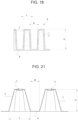
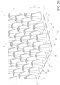
- each projection 7 has a shape chosen from the group consisting of: polyhedral ( figures 2-5 ), cylindrical ( figures 14 and 15 ), conical, truncated cone ( figures 16-18 ), pyramidal, truncated pyramid ( figures 19-21 ).
- the polyhedral shape is a polyhedral form with convex polygonal base (section) with at least four corners (in particular, with at least six corners; more in particular, with at least eight corners).
- the polyhedral shape has a rectangular base (section) (in particular, square - figures 2-5 ).
- the polyhedral shape has an octagonal base (section) (in particular, regular).
- the cylindrical shape is a cylindrical form with section (transverse - perpendicular to the longitudinal extension of the projection 7) substantially circular ( figures 14 and 15 ).
- the conical shape is a conical form with section (transverse - perpendicular to the longitudinal extension of the projection 7) substantially circular ( figures 16-18 ).
- the truncated cone shape is a truncated cone form with section (transverse - perpendicular to the longitudinal extension of the projection 7) substantially circular.
- the pyramidal shape is a pyramidal form with polygonal convex base (section) with at least four corners (in particular, with at least five corners; more in particular, with at least six corners; even more in particular, with at least eight corners).
- the pyramidal shape has an octagonal base (section) (in particular, regular - figures 19-21 ).
- the truncated pyramid shape is a truncated pyramid form with polygonal convex base (section) with at least four corners (in particular, with at least five corners; more in particular, with at least six corners; even more in particular, with at least eight corners).
- the truncated pyramid shape has an octagonal base (section) (in particular, regular).
- convex polygon it is meant a polygon that has all the internal angles smaller than or equal to a flat angle.
- (transverse) section we mean the section perpendicular to the longitudinal extension (from the base portion 6) of the projection 7.
- each projection 7 has a shape chosen from the group consisting of: polyhedral, cylindrical, truncated cone and truncated pyramid.
- each projection 7 has a shape chosen from the group consisting of: cylindrical, truncated cone and truncated pyramid.
- each projection 7 has a shape chosen from the group consisting of: cylindrical and truncated cone.
- the projections 7 having these shapes can be easier to produce (in particular, by means of thermoforming).
- the majority of the (in particular, all the) projections 7 have substantially the same shape.
- each projection 7 has a recess arranged on an upper end (opposite to the base portion 6) of the projection 7. In this way, a better distribution of the forces exerted by the above arrangement on the support 5 is obtained.
- the support 5 (and therefore the projections 7) can be produced by means of thermoforming and/or injection.
- the embodiment of the support 5 illustrated in figures 16 to 18 can be produced by injection; the embodiment of the support 5 illustrated in figures 19 to 21 can be produced by thermoforming.
- end edges 11 and 14 are transverse (in particular, substantially perpendicular) to the end edges 13 and 15.
- the projections 7 have a width L of at least approximately 12 mm (at least approximately 16 mm).
- the width L is up to (no greater than) approximately 30 mm (more in particular, up to 20 mm).
- the recesses 10 (and possibly the recesses 12) have a width B of at least approximately 12 mm (at least approximately 13 mm).
- the width B is up to (no greater than) approximately 20 mm (more in particular, up to 15 mm) .
- the recesses 10 (and possibly, the recesses 12) extend from the end edge 11 (or from the end edge 13) for at least 15 cm.
- the projections 7 have a height H starting from the base portion of at least 12 mm (in particular, at least 20 mm).
- the height H is up to (no greater than) approximately 50 mm (more in particular, up to 30 mm).
- the support 5 has dimensions of approximately 86 cm x 124 cm or approximately 100 cm x 122 cm.
- At least the projections comprise (in particular, are made of): polyethylene (e.g. PE and/or HDPE) and/or polycarbonate (PC) and/or acrylonitrile-butadiene-styrene (ABS) and/or polystyrene (PS) and/or polypropylene (PP) and/or polyvinyl chloride (PVC) and/or wood and/or sheet metal.
- the support 5 comprises (is made of): polyethylene (e.g.
- the support 5 comprises (is made of) polyethylene (e.g. PE and/or HDPE).
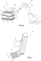
- the system 1 further comprises ( figures 1 and 2 ) a moving device 16 which, in turn, comprises (see, in particular, figure 7 ) at least two tines 17 and is configured to insert at least part of the tines 17 in corresponding recesses 10 (and/or 12) and move (move away) at least one article 2 of the cited group G of articles 2 from the support 5 (in particular, from the input station 3).
- a moving device 16 which, in turn, comprises (see, in particular, figure 7 ) at least two tines 17 and is configured to insert at least part of the tines 17 in corresponding recesses 10 (and/or 12) and move (move away) at least one article 2 of the cited group G of articles 2 from the support 5 (in particular, from the input station 3).
- the moving device 16 is configured to lift the article 2 from the support 5 (in particular, from the input station 3).
- the projections 7 have a rounded (substantially round) or polygonal section with more than four corners, insertion of the tines 17 in the recesses 10 (and/or 12) is facilitated (in particular, in the case of deformations of the projections 7), reducing the risk, among other things, of the tines jamming, sticking and/or damaging the projections 7. This type of advantage is more evident when the projections have a rounded (substantially round) section.
- the moving device 16 comprises at least a countering element 18 (in particular, a countering plate).
- the moving device 16 is configured to clamp (in particular, after inserting the tines 17 in the corresponding recesses 10 - and/or 12) the article 2 (or the articles 2) between the countering element 18 and the tines 17 (bringing the countering element 18 and the tines 17 close to each other so that the countering element 18 and the tines 17 come into contact with the peripheral edge PB).
- the moving device 16 comprises a robotic arm 19.
- the moving device 16 further comprises a holding head 20 (better illustrated in figures 6 and 7 ), which is mounted on the robotic arm 19 (in particular, at one end thereof) and comprises the tines 17, the countering element 18 and an actuator (of known type and not illustrated; e.g. an electric actuator) to move the tines 17 and/or the countering element 18 with respect to each other (in other words, the actuator is configured to move the tines 17 and/or the countering element 18).
- a holding head 20 (better illustrated in figures 6 and 7 ), which is mounted on the robotic arm 19 (in particular, at one end thereof) and comprises the tines 17, the countering element 18 and an actuator (of known type and not illustrated; e.g. an electric actuator) to move the tines 17 and/or the countering element 18 with respect to each other (in other words, the actuator is configured to move the tines 17 and/or the countering element 18).
- the system 1 also comprises a further holding device 21 ( figures 1 and 8 ), which is configured to clamp one or more articles 2 (also inside boxes) and convey it/them to the output station 4.
- the holding device 21 comprises two clamping elements 22 (jaws) configured to laterally clamp one or more articles 2 (also boxes), in particular coming into contact with the relative peripheral edge/s PB.
- the holding device 21 comprises a robotic arm 21'.
- the moving device 16 further comprises a holding head 21", which is mounted on the robotic arm 21' (in particular, at one end thereof) and comprises the clamping elements 22 and an actuator (of known type and not illustrated; e.g. an electric actuator) to move the clamping elements 22 with respect to each other (in other words, the actuator is configured to move one or both the clamping elements 22, moving them close to each other and away from each other).
- a holding head 21 which is mounted on the robotic arm 21' (in particular, at one end thereof) and comprises the clamping elements 22 and an actuator (of known type and not illustrated; e.g. an electric actuator) to move the clamping elements 22 with respect to each other (in other words, the actuator is configured to move one or both the clamping elements 22, moving them close to each other and away from each other).
- the moving device 16 (instead of being an anthropomorphic robotic arm) comprises a first group of base tines 17 and a second group of lifting tines 17' and an actuator (of known type and not illustrated) configured to move (lift) the lifting tines 17' with respect to the base tines 17.
- the base tines 17 are configured to discharge onto the support 5 the weight of the lifting tines 17' and the load supported by said lifting tines 17.
- the tines 17 and 17' (in the configuration illustrated in figure 12 ) are all inserted in the recesses 10 (and/or 12). At this point, the lifting tines 17' (moved by the cited actuator) are lifted, moving the article 2 (or the articles 2) upwards from the support 5 (in particular, from the input station 3 - figure 13 ). In other words (in these cases), the moving device 16 moves the article 2 (or the articles 2) only vertically.
- the transfer station 23 (better described below) is above the support 5 (more precisely, above the group G).
- the moving device 16 also comprises a movement unit (only partially illustrated in figures 11 and 13 ) configured to move the tines 17 and 17' (substantially horizontally) so as to insert them in the (and disinsert them from the) recesses 10 (and/or 12).
- a movement unit (only partially illustrated in figures 11 and 13 ) configured to move the tines 17 and 17' (substantially horizontally) so as to insert them in the (and disinsert them from the) recesses 10 (and/or 12).
- the system 1 comprises at least a control unit (of type known per se and not illustrated) configured to control (and coordinate) the movements of the holding devices 16 and 21.
- a control unit of type known per se and not illustrated
- control unit is configured to coordinate the movements of the holding devices 16 and 21 so that the moving device 16 collects the article 2 (or the articles 2) from the input station 3 (more precisely, from above the support 5) and transfers it (them) (directly) (at a transfer station 23) to the holding device 21, which receives the article 2 (or the articles 2) and takes it to the output station 4 (for example, on a specific pallet 24 - more precisely in a defined position).
- the transfer between the holding devices 16 and 21 can be carried out in a particularly simple manner given that the moving device 16 is configured to support the articles 2 from below (and/or is configured to grip the articles 2 at the top and bottom) and the holding device 21 is configured to grip the articles 2 laterally. Furthermore, the transfer is performed at a distance from the group G.
- the system 1 also comprises a further support 25 (defined as the support 5) arranged at an intermediate station 26 (in particular, arranged between the moving device 16 and the holding device 21).
- the control unit operates the moving device 16 so that the moving device 16 collects the article 2 (or the articles 2) from the input station 3 (more precisely, from above the support 5) and transfers it (them) to the intermediate station 26 on the support 25.
- the control unit operates the holding device 21 so as to collect the article 2 (or the articles 2) from the support 25 and take it to the output station 4 (on the support 25).
- the moving device 16 easily deposits the article 2 (or the articles 2) on the support 25, since the tines 17 can enter (enter) the recesses 10 (or 12) of the support 25. Furthermore, the holding device 21 can easily grip the article/s 2 since, among other things, it has/they have been moved away from the group G present on the support 5.
- system 1 is configured to implement a method as described below.
- a method is provided for transfer of the articles 2 (as defined above) from the input station 3 to the output station 4.
- the method is implemented by the system 1.
- the method entails use of the support 5 and comprises a standing step, during which at least the group G of articles 2 is arranged on the support 5 (more precisely, on said projections 7) at the input station 3; and an insertion step, during which the moving device 16, which comprises at least two tines 17, inserts at least part of the tines 17 in corresponding recesses 10 (in particular, below at least an article 2 of said group G of articles of the ceramic processing industry) of the support 5 (in particular, the movement of the tines 17 is substantially horizontal).
- the first insertion step is (at least partially) simultaneous with the standing step.
- the support 5 is as defined above relative to the system 1.
- the support 5 comprises the projections 7 as defined above relative to the system 1.
- the method also comprises a first gripping step, which comprises the insertion step and during which the moving device 16 clamps (in particular, after the insertion step) the article/s 2 (possibly boxes, for example containing slabs) between the countering element 18 (arranged above the article/s) and the tines 17 (arranged below the article/s).
- the article 2 (or the articles 2) is (are) clamped above and below.
- the first gripping step is (at least partially) simultaneous with the standing step.
- the moving device 16 clamps at least said at least one first article 2 between said countering element 18 and said tines 17, making the countering element 18 and the tines 17 close to one another so that the countering element 18 and the tines 17 come into contact with said peripheral edge PB.
- the method further comprises a moving step, which is (at least partially) subsequent to the insertion step (and possibly to the first gripping step) and during which the moving device 16 moves (in particular, lifts) the article/s 2 from the support 5 (more precisely, from the input station 3; in particular, so as to move it/them away from the group G); and a transport step, during which the article/s 2 is/are taken to the output station 4 (on the pallet 24).
- a moving step which is (at least partially) subsequent to the insertion step (and possibly to the first gripping step) and during which the moving device 16 moves (in particular, lifts) the article/s 2 from the support 5 (more precisely, from the input station 3; in particular, so as to move it/them away from the group G); and a transport step, during which the article/s 2 is/are taken to the output station 4 (on the pallet 24).
- the articles 2 are arranged (on their sides) vertically.
- the articles 2 are arranged in the group G so that at least a lateral portion (at least a side LPB) of the peripheral edge PB of an article 2 is (completely) covered (and is therefore not accessible, for example to a gripper jaw for the transfer of articles) by one or more other articles 2. More in particular, at least a lateral portion (a side LPB) of the peripheral edge PB of an article 2 is in contact with at least a further article 2 (directly or by interposition of the walls of the relative boxes).
- At least a further article 2 (more precisely, the article 2 that covers the side LPB of the peripheral edge PB of the article 2 which is moved - collected - from the input station 3) of the group G remains on the support 5 (in particular, substantially motionless). More precisely, during the moving step (and during the gripping step), the moving device 16 does not touch the cited further article 2 (even more precisely, during the moving step, the further article 2 does not come into contact with any further element).
- the moving device 16 lifts the article 2 (from the support 5) .
- the method comprises a second gripping step, during which the holding device 21 clamps the article/s 2 laterally.
- the second gripping step is (at least partially) subsequent to the moving step.
- the moving device 16 leaves (in particular, cedes; more in particular releases) the article/s 2 so that the article/s 2 is/are transferred to the holding device 21. In particular, this occurs during and/or after the second gripping step.
- the second gripping step is subsequent to the insertion step (more precisely but not necessarily, it is subsequent to the first gripping step).
- the holding device 21 grips the article/s 2 while the article/s 2 is/are still (at least partially) supported by the moving device 16.
- the moving device 16 leaves (in particular, yields; more in particular, releases) the article/s 2, after the second gripping step.
- the holding device 21 clamps the article 2 above the further article/s 2 (which remains/remain on the support 5).
- the holding device 21 takes the article/s 2 to the output station 4.
- the clamping elements 22 (jaws) of the holding device 21 clamp laterally (moving substantially horizontally) the article/s 2 exerting pressure on (coming into contact with) the peripheral edge/s PB.
- the moving device 16 conveys the article/s 2 to the intermediate station 26 on the support 25 (which is defined like the support 5, but can be the same as or different from the support 5). More precisely, the moving device 16 arranges the article/s 2 on the support 25 inserting at least part of the tines 17 in corresponding recesses 12 of the support 25.
- the holding device 21 collects the article/s 2 from the intermediate station 26 (more precisely, from the support 25). Subsequently (during the transport step), typically, the holding device 21 takes the article/s 2 to the output station 4.
- the article/s 2 is/are arranged at the output station 4 in a given position to (in order to) create an assemblage of articles 2 of the ceramic processing industry, in which the position of the articles 2 of the ceramic processing industry is defined.
- the gripping step, the holding step and the transport step are repeated several times (with different articles 2 taken from the same group G or from different groups G) so that further articles 2 of the cited group G and/or of further groups G are arranged at the output station 4 in respective given positions so as to create the assemblage of articles 2.
- the assemblage of articles 2 entails a defined position of each article 2.
Landscapes
- Manipulator (AREA)
- Specific Conveyance Elements (AREA)
Claims (13)
- Verfahren zum Transferieren von Artikeln (2) der keramikverarbeitenden Industrie, insbesondere Platten, von einer Eingangsstation (3) zu einer Ausgangsstation (4);wobei das Verfahren die Verwendung eines ersten Trägers (5) umfasst, der einen Basisabschnitt (6), mehrere Vorsprünge (7), die von dem Basisabschnitt (6) vorstehen, und mehrere erste Vertiefungen (10), die jeweils von den Vorsprüngen (7) begrenzt werden und sich von einem ersten Endrand (11) des ersten Trägers (5) erstrecken, aufweist,wobei das Verfahren einen Aufstellschritt aufweist, während dem wenigstens eine Gruppe (G) von Artikeln der Artikel (2) der keramikverarbeitenden Industrie an der Eingangsstation (3) auf dem ersten Träger (5) angeordnet werden,einen Einsetzschritt, während dem eine Bewegungsvorrichtung (16), die wenigstens zwei Zacken (17) aufweist, wenigstens einen Teil dieser Zacken (17) in die entsprechenden ersten Vertiefungen (10) einsetzt;einen Bewegungsschritt, der an den Einsetzschritt anschließt und während dem die Bewegungsvorrichtung (16) wenigstens einen ersten Artikel (2) der Gruppe (G) von Artikeln der keramikverarbeitenden Industrie von dem ersten Träger (5) bewegt; undeinen Transportschritt, der an den Bewegungsschritt anschließt und während dem der wenigstens eine erste Artikel (2) zu der Ausgangsstation (4) gebracht wird;wobei das Verfahren dadurch gekennzeichnet ist, dass es ferner einen ersten Greifschritt aufweist, der den Einsetzschritt aufweist, und während dem die Bewegungsvorrichtung (16), die wenigstens Gegenelement (18) aufweist, wenigstens den wenigstens einen ersten Artikel (2) zwischen das Gegenelement (18) und die Zacken (17) einspannt; wobei der Bewegungsschritt wenigstens teilweise anschließend an den Greifschritt ist;wobei der wenigstens eine erste Artikel (2) während des Aufstellschritts an der Eingangsstation (3) vertikal auf dem ersten Träger (5) angeordnet wird, so dass er wenigstens auf einem Abschnitt eines eigenen Umfangsrands (PB) aufliegt;wobei der wenigstens eine erste Artikel (2) im Wesentlichen flach ist und den Umfangsrand (PB) und zwei Hauptflächen (FC) hat, welche von dem Umfangsrand (PB) begrenzt werden,wobei die Bewegungsvorrichtung (16) den wenigstens einen ersten Artikel (2) zwischen dem Gegenelement (18) und den Zacken (17) einspannt, wobei sie das Gegenelement (18) und die Zacken (17) nahe aneinander bringt, so dass das Gegenelement (18) und die Zacken (17) in Kontakt mit dem Umfangsrand (PB) kommen.
- Verfahren nach Anspruch 1, das einen zweiten Greifschritt aufweist, während dem eine Haltevorrichtung (21) den wenigstens einen ersten Artikel (2) auf den Seiten einspannt; wobei die Bewegungsvorrichtung (16) den wenigstens einen ersten Artikel (2) (insbesondere während und/oder nach dem zweiten Greifschritt) loslässt, so dass der wenigstens eine erste Artikel (2) zu der Haltevorrichtung (21) transferiert wird; wobei die Haltevorrichtung (21) den wenigstens einen ersten Artikel (2) insbesondere zu der Ausgangsstation (4) bringt.
- Verfahren nach Anspruch 2, wobei jeder erste Artikel (2) wenigstens eine Platte aufweist und von einem jeweiligen Umfangsrand (PB) begrenzt wird; wobei während des zweiten Greifschritts Einspannelemente (22) der Haltevorrichtung (21) den wenigstens einen ersten Artikel (2) seitlich einspannen, wobei sie einen Druck auf den Umfangsrand (PB) ausüben.
- Verfahren nach einem der vorhergehenden Ansprüche, wobei die Vorsprünge (7) auf dem Basisabschnitt (6) angeordnet sind, um erste Reihen (8) zu definieren, wobei jede einzelne der ersten Vertiefungen (10) sich während dem Bewegungsschritt zwischen zwei ersten Reihen (8) direkt nebeneinander erstreckt, wobei der wenigstens eine erste Artikel (2) angehoben wird.
- Verfahren nach einem der vorhergehenden Ansprüche, wobei die Bewegungsvorrichtung (16) den wenigstens einen ersten Artikel (2) zu einer Zwischenstation (26) auf einem zweiten Träger (25), der gleich wie der erste Träger (5) definiert ist, bringt, wobei die Bewegungsvorrichtung (16) den wenigstens einen ersten Artikel (6) auf dem zweiten Träger (25) anordnet, wobei sie wenigstens einen Teil der Zacken (17) in entsprechende erste Vertiefungen (12) des zweiten Trägers (25) einsetzt.
- Verfahren nach einem der Ansprüche 1 bis 4, wobei während des Bewegungsschritts wenigstens ein zweiter Artikel der Gruppe (G) von Artikeln der keramikverarbeitenden Industrie auf dem ersten Träger (5) verbleibt; wobei das Verfahren ferner einen zweiten Greifschritt aufweist, während dem eine Haltevorrichtung (21) den wenigstens einen ersten Artikel (2) auf den Seiten oberhalb des wenigstens einen zweiten Artikels einspannt; wobei die Bewegungsvorrichtung (16) insbesondere nach dem zweiten Greifschritt den wenigstens einen ersten Artikel (2) zurücklässt (insbesondere loslässt), so dass der wenigstens eine erste Artikel (2) zu der Haltevorrichtung (21) transferiert wird.
- Verfahren nach einem der vorhergehenden Ansprüche, wobei der wenigstens eine erste Artikel (2) während des Transportschritts in einer gegebenen Position an der Ausgangsstation (4) angeordnet wird, um eine Sammlung von Artikeln (2) der keramikverarbeitenden Industrie zu erhalten, in welcher die Position der Artikel (2) der keramikverarbeitenden Industrie definiert wird; wobei der Einsetzschritt, der Bewegungsschritt, der Halteschritt und der Transportschritt insbesondere mehrere Male wiederholt werden, so dass weitere Artikel (2) der Gruppe (G) von Artikeln der keramikverarbeitenden Industrie und/oder weitere Gruppen von Artikeln der keramikverarbeitenden Industrie in jeweiligen vorgegebenen Positionen an der Ausgangsstation angeordnet werden, um die Sammlung von Artikeln der keramikverarbeitenden Industrie zu erhalten.
- Verfahren nach einem der vorhergehenden Ansprüche, wobei die Vorsprünge (7) derart auf dem Basisabschnitt (6) angeordnet sind, dass sie erste Reihen (8) definieren, wobei jede einzelne der ersten Vertiefungen (10) sich zwischen zwei ersten Reihen (8) direkt nebeneinander erstreckt,wobei die Vorsprünge (7) auf dem Basisabschnitt (6) angeordnet und konfiguriert sind, dass sie zweite Reihen (9) definieren, die quer zu den ersten Reihen (8) sind,wobei der erste Träger (5) mehrere zweite Vertiefungen (12) aufweist, die sich jeweils von einem zweiten Endrand (13) des ersten Trägers (5) zwischen zwei zweiten Reihen (9) direkt nebeneinander erstrecken, wobei der erste Endrand (11) quer (insbesondere im Wesentlichen senkrecht) zu dem zweiten Endrand (13) ist.
- Verfahren nach Anspruch 8, wobei die ersten Vertiefungen (10) im Wesentlichen senkrecht zu den zweiten Vertiefungen (12) sind, wobei die erste Vertiefungen (10) im Wesentlichen parallel zueinander sind, wobei die zweiten Vertiefungen (12) im Wesentlichen parallel zueinander sind.
- Verfahren nach einem der vorhergehenden Ansprüche, wobei die Vorsprünge (7) von dem Basisabschnitt (6) vorstehen und eine Breite im Bereich von 12 bis 30 mm haben; und wobei die ersten Vertiefungen (10) jeweils eine Breite im Bereich von 12 bis 20 mm haben und sich über wenigstens 15 cm von dem ersten Endrand (11) des ersten Trägers (5) erstrecken, wobei die zweiten Vertiefungen (12) insbesondere eine jeweilige Breite im Bereich von 12 bis 20 mm haben und sich über wenigstens 15 cm von dem zweiten Endrand (13) des ersten Trägers (5) erstrecken.
- Verfahren nach einem der vorhergehenden Ansprüche, wobei die ersten Vertiefungen (10) sich von dem ersten Endrand (11) zu dem dritten Endrand (14) des ersten Trägers (5) erstrecken, wobei der dritte Endrand (14) entgegengesetzt zu dem ersten Endrand (11) ist; wobei die zweiten Vertiefungen (12) sich insbesondere von dem zweiten Endrand (13) zu einem vierten Endrand (15) des ersten Trägers (5) erstrecken, wobei der vierte Endrand (15) entgegengesetzt zu dem zweiten Endrand (13) ist; wobei der erste Endrand (11) und der dritte Endrand (14) quer (insbesondere im Wesentlichen senkrecht) zu dem zweiten Endrand (13) und dem vierten Endrand (15) sind.
- Verfahren nach einem der vorhergehenden Ansprüche, wobei die Vorsprünge (7) beginnend von dem Basisabschnitt (6) eine Höhe von wenigstens 12 mm (zum Beispiel wenigstens ungefähr 20 mm) bis zu ungefähr 50 mm haben; wobei jeder Vorsprung (7) eine Breite von wenigstens 16 mm hat, wobei jede erste Vertiefung (10) eine Breite von wenigstens 13 mm hat, wobei jede zweite Vertiefung (12) eine Breite von wenigstens ? mm hat.
- Verfahren nach einem der vorhergehenden Ansprüche, wobei jeder Vorsprung (7) eine Form hat, die aus der Gruppe ausgewählt wird, die besteht aus: polyedrisch, zylindrisch, kegelförmig, kegelstumpfförmig, pyramidenförmig, pyramidenstumpfförmig.
Applications Claiming Priority (3)
| Application Number | Priority Date | Filing Date | Title |
|---|---|---|---|
| IT102019000007851A IT201900007851A1 (it) | 2019-06-03 | 2019-06-03 | Metodo e sistema per il trasferimento di articoli dell'industria della lavorazione della ceramica |
| IT201900015380 | 2019-09-02 | ||
| PCT/IB2020/055241 WO2020245743A1 (en) | 2019-06-03 | 2020-06-03 | Method and system for transferring articles of the ceramic processing industry |
Publications (2)
| Publication Number | Publication Date |
|---|---|
| EP3976510A1 EP3976510A1 (de) | 2022-04-06 |
| EP3976510B1 true EP3976510B1 (de) | 2024-07-31 |
Family
ID=71452513
Family Applications (1)
| Application Number | Title | Priority Date | Filing Date |
|---|---|---|---|
| EP20736418.3A Active EP3976510B1 (de) | 2019-06-03 | 2020-06-03 | Verfahren zum transferieren von artikeln der keramikverarbeitenden industrie |
Country Status (4)
| Country | Link |
|---|---|
| EP (1) | EP3976510B1 (de) |
| CN (1) | CN114423693B (de) |
| ES (1) | ES2984714T3 (de) |
| WO (1) | WO2020245743A1 (de) |
Family Cites Families (22)
| Publication number | Priority date | Publication date | Assignee | Title |
|---|---|---|---|---|
| US3289860A (en) * | 1964-06-09 | 1966-12-06 | Dean Res Corp | System for handling stacked sheets |
| DE2342782A1 (de) * | 1973-08-24 | 1975-03-06 | Nelskamp Dachziegelwerke Gmbh | Verfahren und vorrichtung zum zusammenfassen von zwei dachziegelpaketen zur vorbereitung der ausbildung eines paketstapels |
| DE3207890A1 (de) * | 1982-03-05 | 1983-09-15 | Laeis-Werke Ag, 5500 Trier | Beschickungsanlage |
| DE3442333C2 (de) * | 1984-10-11 | 1986-10-02 | C. Keller GmbH u. Co KG, 4530 Ibbenbüren | Vorrichtung zum Entladen von Ofenwagen in der keramischen Industrie |
| DE3718601A1 (de) * | 1987-06-03 | 1988-12-22 | Bat Cigarettenfab Gmbh | Vorrichtung zum abheben mindestens eines material-stapels |
| JPH0739285B2 (ja) * | 1987-07-24 | 1995-05-01 | 株式会社日型 | タイル回転移送装置 |
| ATE80858T1 (de) * | 1988-12-31 | 1992-10-15 | System Gmbh | Palettiersystem. |
| IT1252461B (it) * | 1991-07-29 | 1995-06-16 | Gd Spa | Dispositivo per l'alimentazione di pile di sbozzati ad una macchina utilizzatrice |
| JPH0781752A (ja) * | 1993-06-24 | 1995-03-28 | Hekinan Tokushu Kikai Kk | 焼成台車への棚板積み込み・降ろし装置 |
| DE4407392A1 (de) * | 1994-03-05 | 1995-09-07 | Lippert Masch Stahlbau J | Verfahren und Vorrichtung zum automatischen Be- und Entladen von keramischen Artikeln |
| IT1269249B (it) * | 1994-08-19 | 1997-03-26 | Sacs Artigiana Costr Smalta | Macchina impilatrice di materiale piastriforme |
| FR2814161B1 (fr) * | 2000-09-19 | 2003-01-31 | Lucas S A | Dispositif de palettisation a tetes de depose multiples |
| ITMO20060290A1 (it) * | 2006-09-25 | 2008-03-26 | System Spa | Apparato e metodo per la formatura pacchi e composizione pallets di piastrelle ceramiche, in particolare di grande formato. |
| CN202642850U (zh) * | 2012-05-25 | 2013-01-02 | 广东科达机电股份有限公司 | 一种瓷砖夹持翻砖装置 |
| CN203865983U (zh) * | 2014-05-12 | 2014-10-08 | 马志新 | 一种用于瓷砖装卸的叉车属具 |
| CN204138284U (zh) * | 2014-09-30 | 2015-02-04 | 久芳(郑州)生物科技有限公司 | 可压紧运输用的叉车 |
| CN204369087U (zh) * | 2014-11-26 | 2015-06-03 | 佛山市鼎吉包装技术有限公司 | 一种可夹持陶瓷砖包或砖垛的夹持装置 |
| DE102015009177A1 (de) * | 2015-07-09 | 2017-01-12 | Broetje-Automation Gmbh | Verfahren zum Herstellen eines Faser-Metall-Laminatbauteils eines Flugzeugs |
| CN105060184B (zh) * | 2015-09-14 | 2018-01-16 | 佛山市南海区广工大数控装备协同创新研究院 | 一种瓷砖搬运叉车属具 |
| EP3318371B1 (de) * | 2016-11-04 | 2021-07-28 | IPR-Intelligente Peripherien für Roboter GmbH | Robotergreifer, palettierstation mit einem robotergreifer und betriebsverfahren für einen robotergreifer |
| CN207390439U (zh) * | 2017-10-16 | 2018-05-22 | 洛阳中冶建材设备有限公司 | 一种能够预留叉车孔的码垛机械手 |
| CN108996249A (zh) * | 2018-10-25 | 2018-12-14 | 广东赛因迪科技股份有限公司 | 一种瓷砖码垛机构 |
-
2020
- 2020-06-03 ES ES20736418T patent/ES2984714T3/es active Active
- 2020-06-03 WO PCT/IB2020/055241 patent/WO2020245743A1/en not_active Ceased
- 2020-06-03 CN CN202080048199.9A patent/CN114423693B/zh active Active
- 2020-06-03 EP EP20736418.3A patent/EP3976510B1/de active Active
Also Published As
| Publication number | Publication date |
|---|---|
| EP3976510A1 (de) | 2022-04-06 |
| CN114423693A (zh) | 2022-04-29 |
| WO2020245743A1 (en) | 2020-12-10 |
| ES2984714T3 (es) | 2024-10-30 |
| CN114423693B (zh) | 2024-03-22 |
Similar Documents
| Publication | Publication Date | Title |
|---|---|---|
| CN109484821B (zh) | 一种料盘自动送料系统 | |
| US12049371B2 (en) | Method for forming an article array | |
| US8376433B2 (en) | Grab apparatus for handling bins or cases | |
| US20140369800A1 (en) | Palletiser | |
| US20050226711A1 (en) | Process and device for handling objects | |
| NO20160614A1 (en) | A storage bin and storage bin system | |
| ES2703675T3 (es) | Dispositivo y procedimiento de apilado de paquetes de tamaños diferentes | |
| US8337134B2 (en) | Device and method for stacking and/or conveying a plurality of flat substrates | |
| WO2012137082A1 (en) | Palletizing device and method | |
| US20080118340A1 (en) | Method for Palletizing Bottles with Interleaving of Layers | |
| EP3307657B1 (de) | Vorrichtung zur sortierung von gegenständen | |
| CA2549035C (en) | Method and device for handling rod-shaped objects | |
| EP3976510B1 (de) | Verfahren zum transferieren von artikeln der keramikverarbeitenden industrie | |
| US20130029824A1 (en) | Tier cap forming apparatus | |
| EP1359101A2 (de) | Vorrichtung zum Transportieren und Stapeln von flachen Produkten | |
| ES3042448T3 (en) | Gripping device for crates | |
| JP2020512198A (ja) | 積層装置 | |
| WO2020126636A1 (en) | Robotic feeding system | |
| CN211056214U (zh) | 码垛机 | |
| EP4178890B1 (de) | Verfahren und maschine zur handhabung von keramikartikeln einer gruppe von keramikartikeln | |
| RS64626B1 (sr) | Korito za uklanjanje za sistem sa mašinom za obradu kablova, sistem sa mašinom za obradu kablova i postupak za uklanjanje jednog ili više kablova iz korita za uklanjanje | |
| IT201900007851A1 (it) | Metodo e sistema per il trasferimento di articoli dell'industria della lavorazione della ceramica | |
| EP3587284A1 (de) | Ausrüstung und verfahren zum verpacken von objekten | |
| WO1999047439A1 (en) | Improved palletizer | |
| CN102627195A (zh) | 坯车上的斜方波状错位堆垛砖坯堆及其自动码垛方法 |
Legal Events
| Date | Code | Title | Description |
|---|---|---|---|
| STAA | Information on the status of an ep patent application or granted ep patent |
Free format text: STATUS: UNKNOWN |
|
| STAA | Information on the status of an ep patent application or granted ep patent |
Free format text: STATUS: THE INTERNATIONAL PUBLICATION HAS BEEN MADE |
|
| PUAI | Public reference made under article 153(3) epc to a published international application that has entered the european phase |
Free format text: ORIGINAL CODE: 0009012 |
|
| STAA | Information on the status of an ep patent application or granted ep patent |
Free format text: STATUS: REQUEST FOR EXAMINATION WAS MADE |
|
| 17P | Request for examination filed |
Effective date: 20211221 |
|
| AK | Designated contracting states |
Kind code of ref document: A1 Designated state(s): AL AT BE BG CH CY CZ DE DK EE ES FI FR GB GR HR HU IE IS IT LI LT LU LV MC MK MT NL NO PL PT RO RS SE SI SK SM TR |
|
| DAV | Request for validation of the european patent (deleted) | ||
| DAX | Request for extension of the european patent (deleted) | ||
| P01 | Opt-out of the competence of the unified patent court (upc) registered |
Effective date: 20230516 |
|
| GRAP | Despatch of communication of intention to grant a patent |
Free format text: ORIGINAL CODE: EPIDOSNIGR1 |
|
| STAA | Information on the status of an ep patent application or granted ep patent |
Free format text: STATUS: GRANT OF PATENT IS INTENDED |
|
| INTG | Intention to grant announced |
Effective date: 20240221 |
|
| GRAS | Grant fee paid |
Free format text: ORIGINAL CODE: EPIDOSNIGR3 |
|
| GRAA | (expected) grant |
Free format text: ORIGINAL CODE: 0009210 |
|
| STAA | Information on the status of an ep patent application or granted ep patent |
Free format text: STATUS: THE PATENT HAS BEEN GRANTED |
|
| AK | Designated contracting states |
Kind code of ref document: B1 Designated state(s): AL AT BE BG CH CY CZ DE DK EE ES FI FR GB GR HR HU IE IS IT LI LT LU LV MC MK MT NL NO PL PT RO RS SE SI SK SM TR |
|
| REG | Reference to a national code |
Ref country code: CH Ref legal event code: EP Ref country code: GB Ref legal event code: FG4D |
|
| REG | Reference to a national code |
Ref country code: DE Ref legal event code: R096 Ref document number: 602020034871 Country of ref document: DE |
|
| REG | Reference to a national code |
Ref country code: IE Ref legal event code: FG4D |
|
| REG | Reference to a national code |
Ref country code: ES Ref legal event code: FG2A Ref document number: 2984714 Country of ref document: ES Kind code of ref document: T3 Effective date: 20241030 |
|
| REG | Reference to a national code |
Ref country code: LT Ref legal event code: MG9D |
|
| REG | Reference to a national code |
Ref country code: NL Ref legal event code: MP Effective date: 20240731 |
|
| PG25 | Lapsed in a contracting state [announced via postgrant information from national office to epo] |
Ref country code: PT Free format text: LAPSE BECAUSE OF FAILURE TO SUBMIT A TRANSLATION OF THE DESCRIPTION OR TO PAY THE FEE WITHIN THE PRESCRIBED TIME-LIMIT Effective date: 20241202 |
|
| REG | Reference to a national code |
Ref country code: AT Ref legal event code: MK05 Ref document number: 1708302 Country of ref document: AT Kind code of ref document: T Effective date: 20240731 |
|
| PG25 | Lapsed in a contracting state [announced via postgrant information from national office to epo] |
Ref country code: PT Free format text: LAPSE BECAUSE OF FAILURE TO SUBMIT A TRANSLATION OF THE DESCRIPTION OR TO PAY THE FEE WITHIN THE PRESCRIBED TIME-LIMIT Effective date: 20241202 |
|
| PG25 | Lapsed in a contracting state [announced via postgrant information from national office to epo] |
Ref country code: NO Free format text: LAPSE BECAUSE OF FAILURE TO SUBMIT A TRANSLATION OF THE DESCRIPTION OR TO PAY THE FEE WITHIN THE PRESCRIBED TIME-LIMIT Effective date: 20241031 |
|
| PG25 | Lapsed in a contracting state [announced via postgrant information from national office to epo] |
Ref country code: NL Free format text: LAPSE BECAUSE OF FAILURE TO SUBMIT A TRANSLATION OF THE DESCRIPTION OR TO PAY THE FEE WITHIN THE PRESCRIBED TIME-LIMIT Effective date: 20240731 Ref country code: PL Free format text: LAPSE BECAUSE OF FAILURE TO SUBMIT A TRANSLATION OF THE DESCRIPTION OR TO PAY THE FEE WITHIN THE PRESCRIBED TIME-LIMIT Effective date: 20240731 Ref country code: GR Free format text: LAPSE BECAUSE OF FAILURE TO SUBMIT A TRANSLATION OF THE DESCRIPTION OR TO PAY THE FEE WITHIN THE PRESCRIBED TIME-LIMIT Effective date: 20241101 Ref country code: FI Free format text: LAPSE BECAUSE OF FAILURE TO SUBMIT A TRANSLATION OF THE DESCRIPTION OR TO PAY THE FEE WITHIN THE PRESCRIBED TIME-LIMIT Effective date: 20240731 |
|
| PG25 | Lapsed in a contracting state [announced via postgrant information from national office to epo] |
Ref country code: BG Free format text: LAPSE BECAUSE OF FAILURE TO SUBMIT A TRANSLATION OF THE DESCRIPTION OR TO PAY THE FEE WITHIN THE PRESCRIBED TIME-LIMIT Effective date: 20240731 |
|
| PG25 | Lapsed in a contracting state [announced via postgrant information from national office to epo] |
Ref country code: LV Free format text: LAPSE BECAUSE OF FAILURE TO SUBMIT A TRANSLATION OF THE DESCRIPTION OR TO PAY THE FEE WITHIN THE PRESCRIBED TIME-LIMIT Effective date: 20240731 |
|
| PG25 | Lapsed in a contracting state [announced via postgrant information from national office to epo] |
Ref country code: IS Free format text: LAPSE BECAUSE OF FAILURE TO SUBMIT A TRANSLATION OF THE DESCRIPTION OR TO PAY THE FEE WITHIN THE PRESCRIBED TIME-LIMIT Effective date: 20241130 Ref country code: AT Free format text: LAPSE BECAUSE OF FAILURE TO SUBMIT A TRANSLATION OF THE DESCRIPTION OR TO PAY THE FEE WITHIN THE PRESCRIBED TIME-LIMIT Effective date: 20240731 |
|
| PG25 | Lapsed in a contracting state [announced via postgrant information from national office to epo] |
Ref country code: HR Free format text: LAPSE BECAUSE OF FAILURE TO SUBMIT A TRANSLATION OF THE DESCRIPTION OR TO PAY THE FEE WITHIN THE PRESCRIBED TIME-LIMIT Effective date: 20240731 |
|
| PG25 | Lapsed in a contracting state [announced via postgrant information from national office to epo] |
Ref country code: RS Free format text: LAPSE BECAUSE OF FAILURE TO SUBMIT A TRANSLATION OF THE DESCRIPTION OR TO PAY THE FEE WITHIN THE PRESCRIBED TIME-LIMIT Effective date: 20241031 |
|
| PG25 | Lapsed in a contracting state [announced via postgrant information from national office to epo] |
Ref country code: RS Free format text: LAPSE BECAUSE OF FAILURE TO SUBMIT A TRANSLATION OF THE DESCRIPTION OR TO PAY THE FEE WITHIN THE PRESCRIBED TIME-LIMIT Effective date: 20241031 Ref country code: PL Free format text: LAPSE BECAUSE OF FAILURE TO SUBMIT A TRANSLATION OF THE DESCRIPTION OR TO PAY THE FEE WITHIN THE PRESCRIBED TIME-LIMIT Effective date: 20240731 Ref country code: NO Free format text: LAPSE BECAUSE OF FAILURE TO SUBMIT A TRANSLATION OF THE DESCRIPTION OR TO PAY THE FEE WITHIN THE PRESCRIBED TIME-LIMIT Effective date: 20241031 Ref country code: NL Free format text: LAPSE BECAUSE OF FAILURE TO SUBMIT A TRANSLATION OF THE DESCRIPTION OR TO PAY THE FEE WITHIN THE PRESCRIBED TIME-LIMIT Effective date: 20240731 Ref country code: LV Free format text: LAPSE BECAUSE OF FAILURE TO SUBMIT A TRANSLATION OF THE DESCRIPTION OR TO PAY THE FEE WITHIN THE PRESCRIBED TIME-LIMIT Effective date: 20240731 Ref country code: IS Free format text: LAPSE BECAUSE OF FAILURE TO SUBMIT A TRANSLATION OF THE DESCRIPTION OR TO PAY THE FEE WITHIN THE PRESCRIBED TIME-LIMIT Effective date: 20241130 Ref country code: HR Free format text: LAPSE BECAUSE OF FAILURE TO SUBMIT A TRANSLATION OF THE DESCRIPTION OR TO PAY THE FEE WITHIN THE PRESCRIBED TIME-LIMIT Effective date: 20240731 Ref country code: GR Free format text: LAPSE BECAUSE OF FAILURE TO SUBMIT A TRANSLATION OF THE DESCRIPTION OR TO PAY THE FEE WITHIN THE PRESCRIBED TIME-LIMIT Effective date: 20241101 Ref country code: FI Free format text: LAPSE BECAUSE OF FAILURE TO SUBMIT A TRANSLATION OF THE DESCRIPTION OR TO PAY THE FEE WITHIN THE PRESCRIBED TIME-LIMIT Effective date: 20240731 Ref country code: BG Free format text: LAPSE BECAUSE OF FAILURE TO SUBMIT A TRANSLATION OF THE DESCRIPTION OR TO PAY THE FEE WITHIN THE PRESCRIBED TIME-LIMIT Effective date: 20240731 Ref country code: AT Free format text: LAPSE BECAUSE OF FAILURE TO SUBMIT A TRANSLATION OF THE DESCRIPTION OR TO PAY THE FEE WITHIN THE PRESCRIBED TIME-LIMIT Effective date: 20240731 |
|
| PG25 | Lapsed in a contracting state [announced via postgrant information from national office to epo] |
Ref country code: SM Free format text: LAPSE BECAUSE OF FAILURE TO SUBMIT A TRANSLATION OF THE DESCRIPTION OR TO PAY THE FEE WITHIN THE PRESCRIBED TIME-LIMIT Effective date: 20240731 Ref country code: RO Free format text: LAPSE BECAUSE OF FAILURE TO SUBMIT A TRANSLATION OF THE DESCRIPTION OR TO PAY THE FEE WITHIN THE PRESCRIBED TIME-LIMIT Effective date: 20240731 Ref country code: DK Free format text: LAPSE BECAUSE OF FAILURE TO SUBMIT A TRANSLATION OF THE DESCRIPTION OR TO PAY THE FEE WITHIN THE PRESCRIBED TIME-LIMIT Effective date: 20240731 |
|
| PG25 | Lapsed in a contracting state [announced via postgrant information from national office to epo] |
Ref country code: EE Free format text: LAPSE BECAUSE OF FAILURE TO SUBMIT A TRANSLATION OF THE DESCRIPTION OR TO PAY THE FEE WITHIN THE PRESCRIBED TIME-LIMIT Effective date: 20240731 |
|
| PG25 | Lapsed in a contracting state [announced via postgrant information from national office to epo] |
Ref country code: CZ Free format text: LAPSE BECAUSE OF FAILURE TO SUBMIT A TRANSLATION OF THE DESCRIPTION OR TO PAY THE FEE WITHIN THE PRESCRIBED TIME-LIMIT Effective date: 20240731 |
|
| PG25 | Lapsed in a contracting state [announced via postgrant information from national office to epo] |
Ref country code: SK Free format text: LAPSE BECAUSE OF FAILURE TO SUBMIT A TRANSLATION OF THE DESCRIPTION OR TO PAY THE FEE WITHIN THE PRESCRIBED TIME-LIMIT Effective date: 20240731 |
|
| REG | Reference to a national code |
Ref country code: DE Ref legal event code: R097 Ref document number: 602020034871 Country of ref document: DE |
|
| PLBE | No opposition filed within time limit |
Free format text: ORIGINAL CODE: 0009261 |
|
| STAA | Information on the status of an ep patent application or granted ep patent |
Free format text: STATUS: NO OPPOSITION FILED WITHIN TIME LIMIT |
|
| 26N | No opposition filed |
Effective date: 20250501 |
|
| PGFP | Annual fee paid to national office [announced via postgrant information from national office to epo] |
Ref country code: IT Payment date: 20250520 Year of fee payment: 6 |
|
| PG25 | Lapsed in a contracting state [announced via postgrant information from national office to epo] |
Ref country code: SE Free format text: LAPSE BECAUSE OF FAILURE TO SUBMIT A TRANSLATION OF THE DESCRIPTION OR TO PAY THE FEE WITHIN THE PRESCRIBED TIME-LIMIT Effective date: 20240731 |
|
| PGFP | Annual fee paid to national office [announced via postgrant information from national office to epo] |
Ref country code: ES Payment date: 20250701 Year of fee payment: 6 |
|
| REG | Reference to a national code |
Ref country code: DE Ref legal event code: R119 Ref document number: 602020034871 Country of ref document: DE |
|
| REG | Reference to a national code |
Ref country code: CH Ref legal event code: H13 Free format text: ST27 STATUS EVENT CODE: U-0-0-H10-H13 (AS PROVIDED BY THE NATIONAL OFFICE) Effective date: 20260127 |
|
| PG25 | Lapsed in a contracting state [announced via postgrant information from national office to epo] |
Ref country code: MC Free format text: LAPSE BECAUSE OF FAILURE TO SUBMIT A TRANSLATION OF THE DESCRIPTION OR TO PAY THE FEE WITHIN THE PRESCRIBED TIME-LIMIT Effective date: 20240731 |
|
| PG25 | Lapsed in a contracting state [announced via postgrant information from national office to epo] |
Ref country code: LU Free format text: LAPSE BECAUSE OF NON-PAYMENT OF DUE FEES Effective date: 20250603 |
|
| GBPC | Gb: european patent ceased through non-payment of renewal fee |
Effective date: 20250603 |
|
| REG | Reference to a national code |
Ref country code: BE Ref legal event code: MM Effective date: 20250630 |
|
| PG25 | Lapsed in a contracting state [announced via postgrant information from national office to epo] |
Ref country code: GB Free format text: LAPSE BECAUSE OF NON-PAYMENT OF DUE FEES Effective date: 20250603 |
|
| PG25 | Lapsed in a contracting state [announced via postgrant information from national office to epo] |
Ref country code: DE Free format text: LAPSE BECAUSE OF NON-PAYMENT OF DUE FEES Effective date: 20260101 Ref country code: IE Free format text: LAPSE BECAUSE OF NON-PAYMENT OF DUE FEES Effective date: 20250603 |
|
| PG25 | Lapsed in a contracting state [announced via postgrant information from national office to epo] |
Ref country code: BE Free format text: LAPSE BECAUSE OF NON-PAYMENT OF DUE FEES Effective date: 20250630 |
|
| PG25 | Lapsed in a contracting state [announced via postgrant information from national office to epo] |
Ref country code: FR Free format text: LAPSE BECAUSE OF NON-PAYMENT OF DUE FEES Effective date: 20250630 |