EP3975322B1 - Porous carbon structure, manufacturing method therefor, positive electrode material using same, and battery using same - Google Patents
Porous carbon structure, manufacturing method therefor, positive electrode material using same, and battery using same Download PDFInfo
- Publication number
- EP3975322B1 EP3975322B1 EP20809459.9A EP20809459A EP3975322B1 EP 3975322 B1 EP3975322 B1 EP 3975322B1 EP 20809459 A EP20809459 A EP 20809459A EP 3975322 B1 EP3975322 B1 EP 3975322B1
- Authority
- EP
- European Patent Office
- Prior art keywords
- porous carbon
- carbon structure
- less
- positive electrode
- sample
- Prior art date
- Legal status (The legal status is an assumption and is not a legal conclusion. Google has not performed a legal analysis and makes no representation as to the accuracy of the status listed.)
- Active
Links
Images




Classifications
-
- C—CHEMISTRY; METALLURGY
- C01—INORGANIC CHEMISTRY
- C01B—NON-METALLIC ELEMENTS; COMPOUNDS THEREOF; METALLOIDS OR COMPOUNDS THEREOF NOT COVERED BY SUBCLASS C01C
- C01B32/00—Carbon; Compounds thereof
- C01B32/05—Preparation or purification of carbon not covered by groups C01B32/15, C01B32/20, C01B32/25, C01B32/30
-
- C—CHEMISTRY; METALLURGY
- C04—CEMENTS; CONCRETE; ARTIFICIAL STONE; CERAMICS; REFRACTORIES
- C04B—LIME, MAGNESIA; SLAG; CEMENTS; COMPOSITIONS THEREOF, e.g. MORTARS, CONCRETE OR LIKE BUILDING MATERIALS; ARTIFICIAL STONE; CERAMICS; REFRACTORIES; TREATMENT OF NATURAL STONE
- C04B35/00—Shaped ceramic products characterised by their composition; Ceramics compositions; Processing powders of inorganic compounds preparatory to the manufacturing of ceramic products
- C04B35/515—Shaped ceramic products characterised by their composition; Ceramics compositions; Processing powders of inorganic compounds preparatory to the manufacturing of ceramic products based on non-oxide ceramics
- C04B35/52—Shaped ceramic products characterised by their composition; Ceramics compositions; Processing powders of inorganic compounds preparatory to the manufacturing of ceramic products based on non-oxide ceramics based on carbon, e.g. graphite
- C04B35/528—Shaped ceramic products characterised by their composition; Ceramics compositions; Processing powders of inorganic compounds preparatory to the manufacturing of ceramic products based on non-oxide ceramics based on carbon, e.g. graphite obtained from carbonaceous particles with or without other non-organic components
- C04B35/532—Shaped ceramic products characterised by their composition; Ceramics compositions; Processing powders of inorganic compounds preparatory to the manufacturing of ceramic products based on non-oxide ceramics based on carbon, e.g. graphite obtained from carbonaceous particles with or without other non-organic components containing a carbonisable binder
-
- C—CHEMISTRY; METALLURGY
- C04—CEMENTS; CONCRETE; ARTIFICIAL STONE; CERAMICS; REFRACTORIES
- C04B—LIME, MAGNESIA; SLAG; CEMENTS; COMPOSITIONS THEREOF, e.g. MORTARS, CONCRETE OR LIKE BUILDING MATERIALS; ARTIFICIAL STONE; CERAMICS; REFRACTORIES; TREATMENT OF NATURAL STONE
- C04B35/00—Shaped ceramic products characterised by their composition; Ceramics compositions; Processing powders of inorganic compounds preparatory to the manufacturing of ceramic products
- C04B35/622—Forming processes; Processing powders of inorganic compounds preparatory to the manufacturing of ceramic products
- C04B35/626—Preparing or treating the powders individually or as batches ; preparing or treating macroscopic reinforcing agents for ceramic products, e.g. fibres; mechanical aspects section B
- C04B35/62605—Treating the starting powders individually or as mixtures
- C04B35/62625—Wet mixtures
- C04B35/6263—Wet mixtures characterised by their solids loadings, i.e. the percentage of solids
-
- C—CHEMISTRY; METALLURGY
- C04—CEMENTS; CONCRETE; ARTIFICIAL STONE; CERAMICS; REFRACTORIES
- C04B—LIME, MAGNESIA; SLAG; CEMENTS; COMPOSITIONS THEREOF, e.g. MORTARS, CONCRETE OR LIKE BUILDING MATERIALS; ARTIFICIAL STONE; CERAMICS; REFRACTORIES; TREATMENT OF NATURAL STONE
- C04B35/00—Shaped ceramic products characterised by their composition; Ceramics compositions; Processing powders of inorganic compounds preparatory to the manufacturing of ceramic products
- C04B35/622—Forming processes; Processing powders of inorganic compounds preparatory to the manufacturing of ceramic products
- C04B35/626—Preparing or treating the powders individually or as batches ; preparing or treating macroscopic reinforcing agents for ceramic products, e.g. fibres; mechanical aspects section B
- C04B35/62605—Treating the starting powders individually or as mixtures
- C04B35/62625—Wet mixtures
- C04B35/6264—Mixing media, e.g. organic solvents
-
- C—CHEMISTRY; METALLURGY
- C04—CEMENTS; CONCRETE; ARTIFICIAL STONE; CERAMICS; REFRACTORIES
- C04B—LIME, MAGNESIA; SLAG; CEMENTS; COMPOSITIONS THEREOF, e.g. MORTARS, CONCRETE OR LIKE BUILDING MATERIALS; ARTIFICIAL STONE; CERAMICS; REFRACTORIES; TREATMENT OF NATURAL STONE
- C04B35/00—Shaped ceramic products characterised by their composition; Ceramics compositions; Processing powders of inorganic compounds preparatory to the manufacturing of ceramic products
- C04B35/622—Forming processes; Processing powders of inorganic compounds preparatory to the manufacturing of ceramic products
- C04B35/626—Preparing or treating the powders individually or as batches ; preparing or treating macroscopic reinforcing agents for ceramic products, e.g. fibres; mechanical aspects section B
- C04B35/63—Preparing or treating the powders individually or as batches ; preparing or treating macroscopic reinforcing agents for ceramic products, e.g. fibres; mechanical aspects section B using additives specially adapted for forming the products, e.g.. binder binders
- C04B35/632—Organic additives
- C04B35/634—Polymers
- C04B35/63404—Polymers obtained by reactions only involving carbon-to-carbon unsaturated bonds
- C04B35/6344—Copolymers containing at least three different monomers
-
- C—CHEMISTRY; METALLURGY
- C04—CEMENTS; CONCRETE; ARTIFICIAL STONE; CERAMICS; REFRACTORIES
- C04B—LIME, MAGNESIA; SLAG; CEMENTS; COMPOSITIONS THEREOF, e.g. MORTARS, CONCRETE OR LIKE BUILDING MATERIALS; ARTIFICIAL STONE; CERAMICS; REFRACTORIES; TREATMENT OF NATURAL STONE
- C04B35/00—Shaped ceramic products characterised by their composition; Ceramics compositions; Processing powders of inorganic compounds preparatory to the manufacturing of ceramic products
- C04B35/71—Ceramic products containing macroscopic reinforcing agents
- C04B35/78—Ceramic products containing macroscopic reinforcing agents containing non-metallic materials
- C04B35/80—Fibres, filaments, whiskers, platelets, or the like
- C04B35/83—Carbon fibres in a carbon matrix
-
- C—CHEMISTRY; METALLURGY
- C04—CEMENTS; CONCRETE; ARTIFICIAL STONE; CERAMICS; REFRACTORIES
- C04B—LIME, MAGNESIA; SLAG; CEMENTS; COMPOSITIONS THEREOF, e.g. MORTARS, CONCRETE OR LIKE BUILDING MATERIALS; ARTIFICIAL STONE; CERAMICS; REFRACTORIES; TREATMENT OF NATURAL STONE
- C04B38/00—Porous mortars, concrete, artificial stone or ceramic ware; Preparation thereof
- C04B38/08—Porous mortars, concrete, artificial stone or ceramic ware; Preparation thereof by adding porous substances
-
- H—ELECTRICITY
- H01—ELECTRIC ELEMENTS
- H01M—PROCESSES OR MEANS, e.g. BATTERIES, FOR THE DIRECT CONVERSION OF CHEMICAL ENERGY INTO ELECTRICAL ENERGY
- H01M12/00—Hybrid cells; Manufacture thereof
- H01M12/04—Hybrid cells; Manufacture thereof composed of a half-cell of the fuel-cell type and of a half-cell of the primary-cell type
- H01M12/06—Hybrid cells; Manufacture thereof composed of a half-cell of the fuel-cell type and of a half-cell of the primary-cell type with one metallic and one gaseous electrode
-
- H—ELECTRICITY
- H01—ELECTRIC ELEMENTS
- H01M—PROCESSES OR MEANS, e.g. BATTERIES, FOR THE DIRECT CONVERSION OF CHEMICAL ENERGY INTO ELECTRICAL ENERGY
- H01M12/00—Hybrid cells; Manufacture thereof
- H01M12/08—Hybrid cells; Manufacture thereof composed of a half-cell of a fuel-cell type and a half-cell of the secondary-cell type
-
- H—ELECTRICITY
- H01—ELECTRIC ELEMENTS
- H01M—PROCESSES OR MEANS, e.g. BATTERIES, FOR THE DIRECT CONVERSION OF CHEMICAL ENERGY INTO ELECTRICAL ENERGY
- H01M4/00—Electrodes
- H01M4/86—Inert electrodes with catalytic activity, e.g. for fuel cells
- H01M4/8605—Porous electrodes
-
- H—ELECTRICITY
- H01—ELECTRIC ELEMENTS
- H01M—PROCESSES OR MEANS, e.g. BATTERIES, FOR THE DIRECT CONVERSION OF CHEMICAL ENERGY INTO ELECTRICAL ENERGY
- H01M4/00—Electrodes
- H01M4/86—Inert electrodes with catalytic activity, e.g. for fuel cells
- H01M4/88—Processes of manufacture
-
- H—ELECTRICITY
- H01—ELECTRIC ELEMENTS
- H01M—PROCESSES OR MEANS, e.g. BATTERIES, FOR THE DIRECT CONVERSION OF CHEMICAL ENERGY INTO ELECTRICAL ENERGY
- H01M4/00—Electrodes
- H01M4/86—Inert electrodes with catalytic activity, e.g. for fuel cells
- H01M4/88—Processes of manufacture
- H01M4/8878—Treatment steps after deposition of the catalytic active composition or after shaping of the electrode being free-standing body
- H01M4/8882—Heat treatment, e.g. drying, baking
-
- H—ELECTRICITY
- H01—ELECTRIC ELEMENTS
- H01M—PROCESSES OR MEANS, e.g. BATTERIES, FOR THE DIRECT CONVERSION OF CHEMICAL ENERGY INTO ELECTRICAL ENERGY
- H01M4/00—Electrodes
- H01M4/86—Inert electrodes with catalytic activity, e.g. for fuel cells
- H01M4/96—Carbon-based electrodes
-
- C—CHEMISTRY; METALLURGY
- C01—INORGANIC CHEMISTRY
- C01P—INDEXING SCHEME RELATING TO STRUCTURAL AND PHYSICAL ASPECTS OF SOLID INORGANIC COMPOUNDS
- C01P2006/00—Physical properties of inorganic compounds
- C01P2006/12—Surface area
-
- C—CHEMISTRY; METALLURGY
- C01—INORGANIC CHEMISTRY
- C01P—INDEXING SCHEME RELATING TO STRUCTURAL AND PHYSICAL ASPECTS OF SOLID INORGANIC COMPOUNDS
- C01P2006/00—Physical properties of inorganic compounds
- C01P2006/14—Pore volume
-
- C—CHEMISTRY; METALLURGY
- C01—INORGANIC CHEMISTRY
- C01P—INDEXING SCHEME RELATING TO STRUCTURAL AND PHYSICAL ASPECTS OF SOLID INORGANIC COMPOUNDS
- C01P2006/00—Physical properties of inorganic compounds
- C01P2006/16—Pore diameter
-
- C—CHEMISTRY; METALLURGY
- C04—CEMENTS; CONCRETE; ARTIFICIAL STONE; CERAMICS; REFRACTORIES
- C04B—LIME, MAGNESIA; SLAG; CEMENTS; COMPOSITIONS THEREOF, e.g. MORTARS, CONCRETE OR LIKE BUILDING MATERIALS; ARTIFICIAL STONE; CERAMICS; REFRACTORIES; TREATMENT OF NATURAL STONE
- C04B2111/00—Mortars, concrete or artificial stone or mixtures to prepare them, characterised by specific function, property or use
- C04B2111/00474—Uses not provided for elsewhere in C04B2111/00
- C04B2111/00853—Uses not provided for elsewhere in C04B2111/00 in electrochemical cells or batteries, e.g. fuel cells
-
- C—CHEMISTRY; METALLURGY
- C04—CEMENTS; CONCRETE; ARTIFICIAL STONE; CERAMICS; REFRACTORIES
- C04B—LIME, MAGNESIA; SLAG; CEMENTS; COMPOSITIONS THEREOF, e.g. MORTARS, CONCRETE OR LIKE BUILDING MATERIALS; ARTIFICIAL STONE; CERAMICS; REFRACTORIES; TREATMENT OF NATURAL STONE
- C04B2235/00—Aspects relating to ceramic starting mixtures or sintered ceramic products
- C04B2235/02—Composition of constituents of the starting material or of secondary phases of the final product
- C04B2235/30—Constituents and secondary phases not being of a fibrous nature
- C04B2235/42—Non metallic elements added as constituents or additives, e.g. sulfur, phosphor, selenium or tellurium
- C04B2235/422—Carbon
- C04B2235/424—Carbon black
-
- C—CHEMISTRY; METALLURGY
- C04—CEMENTS; CONCRETE; ARTIFICIAL STONE; CERAMICS; REFRACTORIES
- C04B—LIME, MAGNESIA; SLAG; CEMENTS; COMPOSITIONS THEREOF, e.g. MORTARS, CONCRETE OR LIKE BUILDING MATERIALS; ARTIFICIAL STONE; CERAMICS; REFRACTORIES; TREATMENT OF NATURAL STONE
- C04B2235/00—Aspects relating to ceramic starting mixtures or sintered ceramic products
- C04B2235/02—Composition of constituents of the starting material or of secondary phases of the final product
- C04B2235/50—Constituents or additives of the starting mixture chosen for their shape or used because of their shape or their physical appearance
- C04B2235/52—Constituents or additives characterised by their shapes
- C04B2235/5208—Fibers
- C04B2235/5252—Fibers having a specific pre-form
-
- C—CHEMISTRY; METALLURGY
- C04—CEMENTS; CONCRETE; ARTIFICIAL STONE; CERAMICS; REFRACTORIES
- C04B—LIME, MAGNESIA; SLAG; CEMENTS; COMPOSITIONS THEREOF, e.g. MORTARS, CONCRETE OR LIKE BUILDING MATERIALS; ARTIFICIAL STONE; CERAMICS; REFRACTORIES; TREATMENT OF NATURAL STONE
- C04B2235/00—Aspects relating to ceramic starting mixtures or sintered ceramic products
- C04B2235/02—Composition of constituents of the starting material or of secondary phases of the final product
- C04B2235/50—Constituents or additives of the starting mixture chosen for their shape or used because of their shape or their physical appearance
- C04B2235/52—Constituents or additives characterised by their shapes
- C04B2235/5208—Fibers
- C04B2235/526—Fibers characterised by the length of the fibers
-
- C—CHEMISTRY; METALLURGY
- C04—CEMENTS; CONCRETE; ARTIFICIAL STONE; CERAMICS; REFRACTORIES
- C04B—LIME, MAGNESIA; SLAG; CEMENTS; COMPOSITIONS THEREOF, e.g. MORTARS, CONCRETE OR LIKE BUILDING MATERIALS; ARTIFICIAL STONE; CERAMICS; REFRACTORIES; TREATMENT OF NATURAL STONE
- C04B2235/00—Aspects relating to ceramic starting mixtures or sintered ceramic products
- C04B2235/02—Composition of constituents of the starting material or of secondary phases of the final product
- C04B2235/50—Constituents or additives of the starting mixture chosen for their shape or used because of their shape or their physical appearance
- C04B2235/52—Constituents or additives characterised by their shapes
- C04B2235/5208—Fibers
- C04B2235/5264—Fibers characterised by the diameter of the fibers
-
- C—CHEMISTRY; METALLURGY
- C04—CEMENTS; CONCRETE; ARTIFICIAL STONE; CERAMICS; REFRACTORIES
- C04B—LIME, MAGNESIA; SLAG; CEMENTS; COMPOSITIONS THEREOF, e.g. MORTARS, CONCRETE OR LIKE BUILDING MATERIALS; ARTIFICIAL STONE; CERAMICS; REFRACTORIES; TREATMENT OF NATURAL STONE
- C04B2235/00—Aspects relating to ceramic starting mixtures or sintered ceramic products
- C04B2235/02—Composition of constituents of the starting material or of secondary phases of the final product
- C04B2235/50—Constituents or additives of the starting mixture chosen for their shape or used because of their shape or their physical appearance
- C04B2235/54—Particle size related information
- C04B2235/5409—Particle size related information expressed by specific surface values
-
- C—CHEMISTRY; METALLURGY
- C04—CEMENTS; CONCRETE; ARTIFICIAL STONE; CERAMICS; REFRACTORIES
- C04B—LIME, MAGNESIA; SLAG; CEMENTS; COMPOSITIONS THEREOF, e.g. MORTARS, CONCRETE OR LIKE BUILDING MATERIALS; ARTIFICIAL STONE; CERAMICS; REFRACTORIES; TREATMENT OF NATURAL STONE
- C04B2235/00—Aspects relating to ceramic starting mixtures or sintered ceramic products
- C04B2235/60—Aspects relating to the preparation, properties or mechanical treatment of green bodies or pre-forms
- C04B2235/602—Making the green bodies or pre-forms by moulding
- C04B2235/6025—Tape casting, e.g. with a doctor blade
-
- C—CHEMISTRY; METALLURGY
- C04—CEMENTS; CONCRETE; ARTIFICIAL STONE; CERAMICS; REFRACTORIES
- C04B—LIME, MAGNESIA; SLAG; CEMENTS; COMPOSITIONS THEREOF, e.g. MORTARS, CONCRETE OR LIKE BUILDING MATERIALS; ARTIFICIAL STONE; CERAMICS; REFRACTORIES; TREATMENT OF NATURAL STONE
- C04B2235/00—Aspects relating to ceramic starting mixtures or sintered ceramic products
- C04B2235/65—Aspects relating to heat treatments of ceramic bodies such as green ceramics or pre-sintered ceramics, e.g. burning, sintering or melting processes
- C04B2235/656—Aspects relating to heat treatments of ceramic bodies such as green ceramics or pre-sintered ceramics, e.g. burning, sintering or melting processes characterised by specific heating conditions during heat treatment
- C04B2235/6567—Treatment time
-
- C—CHEMISTRY; METALLURGY
- C04—CEMENTS; CONCRETE; ARTIFICIAL STONE; CERAMICS; REFRACTORIES
- C04B—LIME, MAGNESIA; SLAG; CEMENTS; COMPOSITIONS THEREOF, e.g. MORTARS, CONCRETE OR LIKE BUILDING MATERIALS; ARTIFICIAL STONE; CERAMICS; REFRACTORIES; TREATMENT OF NATURAL STONE
- C04B2235/00—Aspects relating to ceramic starting mixtures or sintered ceramic products
- C04B2235/65—Aspects relating to heat treatments of ceramic bodies such as green ceramics or pre-sintered ceramics, e.g. burning, sintering or melting processes
- C04B2235/658—Atmosphere during thermal treatment
- C04B2235/6583—Oxygen containing atmosphere, e.g. with changing oxygen pressures
- C04B2235/6584—Oxygen containing atmosphere, e.g. with changing oxygen pressures at an oxygen percentage below that of air
-
- C—CHEMISTRY; METALLURGY
- C04—CEMENTS; CONCRETE; ARTIFICIAL STONE; CERAMICS; REFRACTORIES
- C04B—LIME, MAGNESIA; SLAG; CEMENTS; COMPOSITIONS THEREOF, e.g. MORTARS, CONCRETE OR LIKE BUILDING MATERIALS; ARTIFICIAL STONE; CERAMICS; REFRACTORIES; TREATMENT OF NATURAL STONE
- C04B2235/00—Aspects relating to ceramic starting mixtures or sintered ceramic products
- C04B2235/65—Aspects relating to heat treatments of ceramic bodies such as green ceramics or pre-sintered ceramics, e.g. burning, sintering or melting processes
- C04B2235/658—Atmosphere during thermal treatment
- C04B2235/6586—Processes characterised by the flow of gas
-
- C—CHEMISTRY; METALLURGY
- C04—CEMENTS; CONCRETE; ARTIFICIAL STONE; CERAMICS; REFRACTORIES
- C04B—LIME, MAGNESIA; SLAG; CEMENTS; COMPOSITIONS THEREOF, e.g. MORTARS, CONCRETE OR LIKE BUILDING MATERIALS; ARTIFICIAL STONE; CERAMICS; REFRACTORIES; TREATMENT OF NATURAL STONE
- C04B2235/00—Aspects relating to ceramic starting mixtures or sintered ceramic products
- C04B2235/65—Aspects relating to heat treatments of ceramic bodies such as green ceramics or pre-sintered ceramics, e.g. burning, sintering or melting processes
- C04B2235/66—Specific sintering techniques, e.g. centrifugal sintering
- C04B2235/661—Multi-step sintering
- C04B2235/662—Annealing after sintering
- C04B2235/663—Oxidative annealing
-
- C—CHEMISTRY; METALLURGY
- C04—CEMENTS; CONCRETE; ARTIFICIAL STONE; CERAMICS; REFRACTORIES
- C04B—LIME, MAGNESIA; SLAG; CEMENTS; COMPOSITIONS THEREOF, e.g. MORTARS, CONCRETE OR LIKE BUILDING MATERIALS; ARTIFICIAL STONE; CERAMICS; REFRACTORIES; TREATMENT OF NATURAL STONE
- C04B2235/00—Aspects relating to ceramic starting mixtures or sintered ceramic products
- C04B2235/65—Aspects relating to heat treatments of ceramic bodies such as green ceramics or pre-sintered ceramics, e.g. burning, sintering or melting processes
- C04B2235/66—Specific sintering techniques, e.g. centrifugal sintering
- C04B2235/661—Multi-step sintering
- C04B2235/662—Annealing after sintering
- C04B2235/664—Reductive annealing
-
- C—CHEMISTRY; METALLURGY
- C04—CEMENTS; CONCRETE; ARTIFICIAL STONE; CERAMICS; REFRACTORIES
- C04B—LIME, MAGNESIA; SLAG; CEMENTS; COMPOSITIONS THEREOF, e.g. MORTARS, CONCRETE OR LIKE BUILDING MATERIALS; ARTIFICIAL STONE; CERAMICS; REFRACTORIES; TREATMENT OF NATURAL STONE
- C04B2235/00—Aspects relating to ceramic starting mixtures or sintered ceramic products
- C04B2235/70—Aspects relating to sintered or melt-casted ceramic products
- C04B2235/72—Products characterised by the absence or the low content of specific components, e.g. alkali metal free alumina ceramics
- C04B2235/724—Halogenide content
-
- C—CHEMISTRY; METALLURGY
- C04—CEMENTS; CONCRETE; ARTIFICIAL STONE; CERAMICS; REFRACTORIES
- C04B—LIME, MAGNESIA; SLAG; CEMENTS; COMPOSITIONS THEREOF, e.g. MORTARS, CONCRETE OR LIKE BUILDING MATERIALS; ARTIFICIAL STONE; CERAMICS; REFRACTORIES; TREATMENT OF NATURAL STONE
- C04B2235/00—Aspects relating to ceramic starting mixtures or sintered ceramic products
- C04B2235/70—Aspects relating to sintered or melt-casted ceramic products
- C04B2235/74—Physical characteristics
- C04B2235/77—Density
-
- H—ELECTRICITY
- H01—ELECTRIC ELEMENTS
- H01M—PROCESSES OR MEANS, e.g. BATTERIES, FOR THE DIRECT CONVERSION OF CHEMICAL ENERGY INTO ELECTRICAL ENERGY
- H01M4/00—Electrodes
- H01M4/86—Inert electrodes with catalytic activity, e.g. for fuel cells
- H01M2004/8678—Inert electrodes with catalytic activity, e.g. for fuel cells characterised by the polarity
- H01M2004/8689—Positive electrodes
-
- Y—GENERAL TAGGING OF NEW TECHNOLOGICAL DEVELOPMENTS; GENERAL TAGGING OF CROSS-SECTIONAL TECHNOLOGIES SPANNING OVER SEVERAL SECTIONS OF THE IPC; TECHNICAL SUBJECTS COVERED BY FORMER USPC CROSS-REFERENCE ART COLLECTIONS [XRACs] AND DIGESTS
- Y02—TECHNOLOGIES OR APPLICATIONS FOR MITIGATION OR ADAPTATION AGAINST CLIMATE CHANGE
- Y02E—REDUCTION OF GREENHOUSE GAS [GHG] EMISSIONS, RELATED TO ENERGY GENERATION, TRANSMISSION OR DISTRIBUTION
- Y02E60/00—Enabling technologies; Technologies with a potential or indirect contribution to GHG emissions mitigation
- Y02E60/10—Energy storage using batteries
Definitions
- the present invention relates to a porous carbon structure, a method for manufacturing the same, a positive electrode material using the same, and a battery using the same.
- the present invention relates to a porous carbon structure that has, in particular, all of self-supporting ability, high ion transport efficiency, high air permeability, and a wide reaction area, and that is suitable for a material for a positive electrode (in the present application, the material may also be referred to as "positive electrode material” or “positive electrode structure”) of a metal air battery, and a battery using the porous carbon structure.
- the air battery is a battery in which oxygen in the air is used as a positive electrode active material, and a metal is used as a negative electrode active material.
- the air battery is also called a metal-air battery, and is regarded as a kind of fuel cell.
- the air battery is disclosed in, for example, Patent Literatures 1 and 2, and representative examples of the air battery include a lithium-air battery in which a metal or compound capable of occluding and releasing lithium ions is used as a negative electrode active material.
- the positive electrode active material is oxygen in the air, and the positive electrode active material can be supplied from the outside of the battery. Therefore, the air battery can be reduced in size and weight, and further has a structure suitable for increasing the capacity.
- One of the causes lies in the positive electrode structure.
- the positive electrode structure is required to have a structure capable of taking in a large amount of oxygen from the air.
- the positive electrode structure is required to have high air or oxygen permeability.
- the positive electrode structure is required to have both high ion transport efficiency and a wide reaction field, which are characteristics generally required of the batteries.
- the positive electrode structure be self-supportable.
- carbon is preferred as a material of the positive electrode structure.
- a positive electrode structure that is made porous for achieving high air or oxygen permeability, that is, a porous carbon structure is often used.
- Ketjen Black (registered trademark) is known as a material having a large total specific surface area (BET specific surface area) as well as a material having a large pore volume and specific surface area of so-called mesopores of a pore diameter of 2 nm or more and 50 nm or less and macropores having a pore diameter of 50 nm or more.
- Ketjen Black is used as a raw material of a porous carbon structure used in a positive electrode of an air battery.
- Ketjen Black (registered trademark) is powdery and is not self-supportable.
- Ketjen Black registered trademark
- Patent Literature 1 proposes use of porous carbon as a raw material of a positive electrode layer, wherein the porous carbon includes pores including mesopores and micropores having a pore diameter smaller than that of the mesopores, carbonaceous walls that constitute an outer contour of the mesopores form a three-dimensional network structure, the micropores are formed in the carbonaceous walls, the mesopores are open pores, pore portions continuously form connecting pores, a half width of a pore size distribution of the pores is 2 nm or less, a half width of a connecting pore size distribution of the connecting pores is 50 nm or more, and a pore volume of pores having a pore diameter of 1 nm or more is 1.0 ml/g or more and 4.0 ml/g or less.
- Patent Literature 1 it is described that in the formation of the positive electrode layer, a method in which a composition containing porous carbon, a binder, and the like is dispersed in a solvent and the composition is applied by means of a doctor blade method or the like, or a method in which the composition is made by pressure molding can be used.
- Patent Literature 2 proposes a lithium-air battery using a positive electrode layer in which a first pore volume of pores having a pore diameter of 1 nm or more and 200 nm or less is larger than a second pore volume of pores having a pore diameter of more than 200 nm and 1000 nm or less.
- a method for forming the positive electrode layer for example, a method of applying a coating material obtained by dispersing a composition containing a conductive porous material, a binder, and the like in a solvent to a positive electrode current collector by means of a doctor blade method or the like, or a method of molding the above composition made by pressure molding.
- Ketjen Black (registered trademark) is disclosed in, for example, Non-Patent Literatures 1 and 2.
- US 9,550,167 relates to a method of preparing a hollow carbon structure.
- the method includes a step of calcining a solid component separated after a cracking reaction of a heavy hydrocarbon fraction; and a step of performing an acid treatment or base treatment on the solid component calcined in the above-described step.
- the hollow carbon structure may be used to separate carbon dioxide, to remove a sulfur compound, and as a carrier of various substances by performing various pre-processes on carbon generated on a surface of a spent catalyst which is used in a cracking reaction of a heavy hydrocarbon fraction.
- JP 2015-026482 A addresses the problem pf providing a porous carbon material capable of making current density higher than that of the conventional air cells by being used for an air cell and providing a process of manufacturing the same.
- the disclosed porous carbon material used for a positive electrode of an air cell includes: pores having an average pore size of 1 to 10 ⁇ m; and mesopores having an average pore size equal to or less than 50 nm.
- An object of the present invention is to provide a battery which is small in size and light in weight as well as which is suitable for increasing the capacity, particularly an air battery which is small in size and light in weight as well as which is suitable for increasing the capacity.
- an object of the present invention is to provide a porous carbon structure that has all of high air or oxygen permeability, high ion transport efficiency, and a wide reaction field, the porous carbon structure being suitable as a positive electrode structure of an air battery, particularly a self-supportable porous carbon structure.
- Patent Literature 2 which uses a positive electrode layer in which the first pore volume of pores having a pore diameter of 1 nm or more and 200 nm or less is larger than the second pore volume of pores having a pore diameter of more than 200 nm and 10,000 nm or less
- the binder is used to form the positive electrode layer. Therefore, as in the case of Patent Literature 1, some of the pores of the porous carbon as a raw material are directly filled with the binder, and the pore volume in the positive electrode layer may become smaller than the pore volume in the porous carbon of the raw material, and the absolute amount of the pore volume in the positive electrode layer is not large. Therefore, it cannot be said that required sufficient battery performance is exhibited.
- a positive electrode layer inheriting the pore volume in porous carbon of a raw material is desired, and a positive electrode layer having a large pore volume exceeding the pore volume in porous carbon as a raw material is further desired.
- porous carbon materials it is common that the first pore volume of pores having a pore diameter of 1 nm or more and 200 nm or less is larger than the second pore volume of pores having a pore diameter of more than 200 nm and 10,000 nm or less.
- an object of the present invention is to provide a porous carbon structure that has a high pore volume and is self-supportable, a method for manufacturing the same, a positive electrode material using the same, and a battery (particularly an air battery) using the same.
- the present invention specifically has the following configuration.
- the present invention it becomes possible to provide a battery which is small in size and light in weight as well as which is suitable for increasing the discharge capacity, particularly an air battery which is small in size and light in weight as well as which is suitable for increasing the capacity.
- the air battery which is small in size and light in weight as well as which is suitable for increasing the capacity is provided by the porous carbon structure of the present invention, which has all of high air or oxygen permeability, high ion transport efficiency, and a wide reaction field as well as which is self-supportable.
- the porous carbon structure of the present invention has a large number of pores and a skeleton containing carbon, and can satisfy all of the above-mentioned conditions (a) to (e).
- a porous carbon structure has an unprecedented high pore volume and is self-supportable.
- Such a porous carbon structure may be used as a positive electrode material for an air battery. Since such a porous carbon structure itself is self-supportable, when the porous carbon structure is used in a positive electrode structure, a current collector such as a metal mesh is unnecessary, and the air battery can be reduced in size and weight.
- the porous carbon structure has an unprecedented high pore volume
- the porous carbon structure has high air or oxygen permeability, high ion transport efficiency, and a large reaction field, so that an air battery having high-capacity and high-load characteristics can be provided.
- the method for manufacturing the porous carbon structure of the present invention includes the steps of: preparing a mixture slurry containing 50 wt% to 85 wt% of porous carbon particles, 1 wt% to 15 wt% of carbon fibers, 5 wt% to 49 wt% of a binding polymer material and a solvent, molding the mixture slurry, immersing a sample obtained by the molding step in a solvent in which the binding polymer material has low solubility, drying the sample obtained by the immersing step, and subjecting the sample obtained by the drying step to a carbonization treatment wherein the carbonization treatment is performed in an atmosphere of an oxidizing gas.
- the method can provide the above-mentioned porous carbon structure having a high pore volume and being self-supportable.
- the carbonization treatment can burn off and eliminate the binding polymer material and further burn off and eliminate a part of the porous carbon particles, so that the binding between the porous carbon particles can be formed.
- the oxidizing gas has an oxygen concentration in the range of more than 0.03% and less than 5%, the above-mentioned porous carbon structure having a high pore volume and being self-supportable can be provided.
- the porous carbon structure that has self-supporting ability or that is self-supportable refers to a film-like structure capable of maintaining the shape as a film that is self-supporting without using a support (in the present application, the structure may also be referred to as "self-supporting film”).
- the porous carbon structure is formed from a skeleton mainly containing carbon, and is used in a thickness within the range of 20 ⁇ m to 800 ⁇ m, preferably within the range of 50 ⁇ m to 500 ⁇ m.
- the porous carbon structure in the meaning of the present invention means that in a positive electrode layer, a support, for example, a metal mesh made of a simple metal such as copper (Cu), tungsten (W), aluminum (Al), nickel (Ni), titanium (Ti), gold (Au), silver (Ag), platinum (Pt), palladium (Pd), or stainless steel (SUS), or an alloy containing a metal-containing component, and a nonwoven or woven fabric consisting of components such as carbon fibers and polyester fibers is not included, or means that the positive electrode layer is not formed on a metal foil substrate, such as aluminum foil, nickel foil, or SUS foil.
- a metal mesh made of a simple metal such as copper (Cu), tungsten (W), aluminum (Al), nickel (Ni), titanium (Ti), gold (Au), silver (Ag), platinum (Pt), palladium (Pd), or stainless steel (SUS), or an alloy containing a metal-containing component, and a nonwoven or woven fabric consisting of
- the porous carbon structure does not contain an organic binder that is intended for adhesion to a support or a substrate, particularly a fluorine-containing binder.
- a fluorine content is 0.0002 mass% or less.
- the porous carbon structure may be a self-supporting body having practical rigidity and mechanical strength as well as flexibility.
- FIG. 1 is a diagram schematically showing a cross section of a porous carbon structure of the present invention.
- FIG. 2 is an enlarged view of a part A in FIG. 1 .
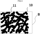
- FIG. 3 is an enlarged view of a part B in FIG. 2 .
- the porous carbon structure of the present invention has a skeleton 10 containing carbon, and a large number of pores 11 and 12. Furthermore, the porous carbon structure of the present invention satisfies all of conditions (a) to (e) shown as follows:
- the "t-plot external specific surface area" in the above-mentioned condition (a) is determined from a graph of an adsorption isotherm obtained by nitrogen adsorption measurement, the graph plotting the layer thickness of adsorbed nitrogen on the horizontal axis and the amount of adsorbed nitrogen on the vertical axis.
- the pores represented as t-plot micropores are too small to allow entry of lithium ions and oxygen, and hardly contribute to a discharge reaction.
- the t-plot external specific surface area represents a specific surface area of pores effective for a discharge reaction and further a charge reaction.
- the definition of pores is described by the IUPAC, and micropores are defined as pores having a pore diameter of less than 2 nm, mesopores are defined as pores having a pore diameter of 2 nm or more and less than 50 nm, and macropores are defined as pores having a pore diameter of 50 nm or more.
- the t-plot external specific surface area is in the range of the above-mentioned condition (a) (that is, the area is in the range of 900 m 2 /g or more and 1,600 m 2 /g or less).
- the porous carbon structure has a t-plot external specific surface area of 900 m 2 /g or more, the problem is avoided that the porous carbon structure has lower air permeability and ion transport efficiency, and a reaction field when used as a positive electrode structure of a battery becomes narrower, which may occur when the t-plot external specific surface area is less than 300 m 2 /g.
- the porous carbon structure has a t-plot external specific surface area in the range of 1,600 m 2 /g or less, the problem is avoided that micropores tend to relatively increase, so that entry of lithium ions and oxygen may be difficult, which may occur when the t-plot external specific surface area is more than the above-mentioned value.
- the lower limit of the t-plot external specific surface area is 900 m 2 /g or more, it is easier to avoid the problem that the fields where lithium ions and oxygen react with each other are reduced, so that the discharge capacity may decrease. Therefore, the lower limit of the t-plot external specific surface area is 900 m 2 /g or more.
- the t-plot external specific surface area is in the range of 900 m 2 /g or more and 1,600 m 2 /g or less.
- the t-plot external specific surface area is in the above-mentioned range, in a case where Li ions and oxygen react with each other in a discharge reaction to generate lithium peroxide, there are many reaction fields required for oxygen to receive electrons supplied from the positive electrode. This makes more electron-transfer possible.
- a battery having high discharge capacity can be provided.
- the t-plot external specific surface area is more preferably in the range of 930 m 2 /g or more and 1,500 m 2 /g or less. Such a value enables high discharge capacity and high-speed charging.
- the t-plot external specific surface area is further more preferably 950 m 2 /g or more and 1,400 m 2 /g or less. Such a value enables further higher discharge capacity and high-speed charging.
- a pore volume of pores having a diameter of 1 nm or more and 200 nm or less in the range of 2.2 cm 3 /g or more and 7.0 cm 3 /g or less means that the pore volume and the number of pores are large although the pores included in this range have a relatively small pore diameter.
- the pores having a diameter of 1 nm or more and 200 nm or less may correspond to the pores 11 in FIGS. 2 and 3 .
- the pore volume is determined by means of the BJH method from an adsorption isotherm obtained by nitrogen adsorption measurement.
- the pore volume of pores having a diameter of 1 nm or more and 200 nm or less is in the range of the above-mentioned condition (b) (that is, the pore volume is in the range of 2.2 cm 3 /g or more and 7.0 cm 3 /g or less), the problem is avoided that the discharge capacity tends to decrease, which may occur when the pore volume is smaller than 1.2 cm 3 /g, and the problem is avoided that the pore volume of pores having a diameter of 200 nm or more relatively decreases, whereby the oxygen permeability and diffusivity decreases, and the discharge characteristics at high load, that is, the discharge capacity at high speed may decrease, which may occur when the pore volume is larger than the above-mentioned range.
- the lower limit of the pore volume is in the range of 2.2 cm 3 /g or more, and preferably 2.4 cm 3 /g or more, and the upper limit of the pore volume is in the range of 7.0 cm 3 /g or less, and preferably 6.0 cm 3 /g or less.
- Such a value may enable the battery to have a large discharge capacity.
- Such a value may enable the battery to have even larger discharge capacity.
- a pore volume of pores having a diameter of 1 nm or more and 1,000 nm or less in the range of 4.0 cm 3 /g or more and 10.0 cm 3 /g or less means that in the porous carbon structure of the present invention, the pore volume of pores having a diameter in the above-mentioned range is considerably large.
- the pores having a diameter of 1 nm or more and 1,000 nm or less may correspond to the pores 11 in FIGS. 2 and 3 .
- the pore volume is determined by means of the BJH (Barrett-Joyner-Halenda) method from an adsorption isotherm obtained by nitrogen adsorption measurement.
- porous carbon structure of the present invention When such a porous carbon structure of the present invention is used in a positive electrode (positive electrode structure) of an air battery, more lithium peroxide generated by discharge can be stored, and a battery having high discharge capacity characteristics can be provided.
- the pores in this pore range have a large pore volume, permeation and diffusion of air or oxygen is facilitated in the porous carbon structure. Therefore, air or oxygen introduced into the positive electrode from the outside of the battery can spread at high speed throughout the carbon particles forming the carbon skeleton.
- the pores in this pore range have a large pore volume, lithium (Li) ions move smoothly, and in combination with high air or oxygen permeability and diffusivity, an air battery excellent in high-speed discharge characteristics, that is, high-load characteristics can be provided.
- the pore volume of pores having a diameter of 1 nm or more and 1,000 nm or less is in the range of the above-mentioned condition (c) (that is, the pore volume is in the range of 4.0 cm 3 /g or more and 10.0 cm 3 /g or less), the problem is avoided that the discharge capacity and high-load characteristics tend to decrease, which may occur when the pore volume is smaller than 2.3 cm 3 /g, and the problem is avoided that although larger discharge capacity and high-load characteristics can be expected, the porous carbon structure may have lower strength, which may occur when the pore volume is larger than the above-mentioned range.
- the lower limit of the pore volume is in the range of 4.0 cm 3 /g or more, and preferably 4.1 cm 3 /g or more, and the upper limit of the pore volume is in the range of 10.0 cm 3 /g or less, and preferably 9.0 cm 3 /g or less.
- Such a value may enable the achievement of larger discharge capacity and high-load characteristics.
- the porous carbon structure is easy to be self-supportable.
- the "porosity" in the above-mentioned condition (d) is determined from the apparent density and the true density of the porous carbon structure according to the following calculation formula: (1 - apparent density of porous carbon structure/true density of constituent material of porous carbon structure) ⁇ 100.
- porous carbon structure of the present invention is in the range of the above-mentioned condition (d) (that is, the overall porosity is in the range of 92% or more and 99% or less) means that the porous carbon structure has a sufficiently high porosity.
- the porous carbon structure of the present invention has an overall porosity of 92% or more, the problem is avoided that the porous carbon structure has lower air permeability and ion transport efficiency, and the reaction field when used as a positive electrode structure of a battery becomes narrower, which may occur when the overall porosity is less than 80%.
- the porous carbon structure has an overall porosity of 99% or less, the problem is avoided that rigidity as a porous carbon structure is reduced, the porous carbon structure becomes brittle, and the porous carbon structure may hardly have self-supporting ability, which may occur when the overall porosity is more than the above-mentioned value.
- the lower limit of the overall porosity is 90% or more, it is easier to avoid the problem that the production field of lithium peroxide is reduced and the entry of air or oxygen is delayed, so that the discharge capacity and high-load characteristics may decrease. Therefore, the lower limit of the overall porosity is 92% or more.
- the upper limit of the porosity is 99% or less, and preferably 98% or less.
- porous carbon structure of the present invention is not particularly limited as long as the porous carbon structure satisfies all of the above-mentioned conditions (a) to (e).
- the porous carbon structure of the present invention may contain carbon fibers 13.
- the carbon fibers 13 may be carbon fibers having a fiber diameter of 0.1 ⁇ m or more and 20 ⁇ m or less and a length of 1 mm or more and 20 mm or less. This can increase the strength of the porous carbon structure.
- the porous carbon structure of the present invention satisfies the above-mentioned condition (e) "a pore volume of pores having a diameter of 200 nm or more and 10,000 nm or less in the range of 2.3 cm 3 /g or more and 8.0 cm 3 /g or less".
- An image of pores satisfying the above-mentioned condition (e) "a pore volume of pores having a diameter of 200 nm or more and 10,000 nm or less in the range of 2.3 cm 3 /g or more and 8.0 cm 3 /g or less" corresponds to the pores 12 in FIG. 2 and FIG. 8 .
- the pore volume of pores having a diameter of 200 nm or more and 10,000 nm or less is determined using a value obtained by the mercury intrusion method.
- the pores in this region mainly serve to allow oxygen outside the battery to enter the inside of the porous carbon structure as a positive electrode. Since the pore volume in this region is sufficiently large, a sufficient amount of oxygen can enter at high speed in the course in which lithium ions react with oxygen to generate lithium peroxide. Thus, using the porous carbon structure of the present invention in a positive electrode can provide a battery having a large discharge capacity at a high current density, that is, excellent high-load characteristics. Also, in charging, lithium peroxide transfers electrons to the electrode and is decomposed into Li ions and oxygen. Since the pore volume of pores having a diameter of 200 nm or more and 10,000 nm or less is in the above-mentioned range, the generated oxygen leaves the porous carbon structure more easily, and high-speed charging becomes possible.
- the pore volume of pores having a diameter of 200 nm or more and 10,000 nm or less is in the range of the above-mentioned condition (e) (in the range of 2.3 cm 3 /g or more and 8.0 cm 3 /g or less), the problem is avoided that the entry speed of oxygen is reduced and high-load characteristics may be lowered, which may occur when the pore volume is smaller than the above-mentioned range, and the problem is avoided that the porous carbon structure may have lower strength, which may occur when the pore volume is larger than the above-mentioned range.
- the lower limit of the pore volume is preferably in the range of 2.5 cm 3 /g or more, and more preferably 2.6 cm 3 /g or more, and the upper limit of the pore volume is preferably in the range of 7.0 cm 3 /g or less, and more preferably 6.5 cm 3 /g or less.
- Such a value may enable the battery to have high-load characteristics.
- Such a value may enable the battery to have high-load characteristics while maintaining the strength of the porous carbon structure.
- the pore volume of pores having a diameter of 1 nm or more and 200 nm or less in the above-mentioned condition (b) and the pore volume of pores having a diameter of 200 nm or more and 10,000 nm or less in the above-mentioned condition (e) are not particularly limited as long as the pore volumes are respectively in the above-mentioned ranges.
- the pore volume of pores having a diameter of 200 nm or more and 10,000 nm or less in the above-mentioned condition (e) be about the same as the pore volume of pores having a diameter of 1 nm or more and 200 nm or less in the above-mentioned condition (b), and it is still more preferred that the pore volume of pores having a diameter of 200 nm or more and 10,000 nm or less in the above-mentioned condition (e) be larger than the pore volume of pores having a diameter of 1 nm or more and 200 nm or less in the above-mentioned condition (b).
- the pores having a diameter of 200 nm or more and 10,000 nm or less in the above-mentioned condition (e) mainly serve to allow oxygen outside the battery to enter the inside of the porous carbon structure as a positive electrode during the discharge process and to allow oxygen generated during the charge process to leave from the porous carbon structure, and also serve to store lithium peroxide generated during the discharge.
- the porous carbon structure of the present invention preferably has an apparent density in the range of 0.05 g/cm 3 or more and 0.20 g/cm 3 or less.
- the porous carbon structure has sufficient pores necessary for permeation and diffusion of oxygen, and has sufficient strength.
- the porous carbon structure of the present invention since the porous carbon structure of the present invention has self-supporting ability, the porous carbon structure can serve as a positive electrode of an air battery without using a metal mesh or the like. This makes the reduction of the weight and size of the battery, the improvement of the productivity, and the cost reduction possible.
- the apparent density is in the above-mentioned range (in the range of 0.05 g/cm 3 or more and 0.20 g/cm 3 or less)
- the problem is avoided that the strength of the porous carbon structure may be reduced and it may be necessary to attach the porous carbon structure to a current collector such as a metal mesh to form a positive electrode, which may occur when the apparent density is smaller than the above-mentioned range
- the problem is avoided that the amount of pores in the porous carbon structure may be relatively small, and the capacity and load characteristics may decrease, which may occur when the apparent density is larger than the above-mentioned range.
- the lower limit of the apparent density is preferably in the range of 0.07 g/cm 3 or more, and more preferably 0.09 g/cm 3 or more, and the upper limit of the apparent density is preferably in the range of 0.18 g/cm 3 or less, and more preferably 0.17 g/cm 3 or less.
- the porous carbon structure can have pores and have high strength.
- the porous carbon structure of the present invention can further have more pores and higher strength.
- the skeleton manly contains carbon. It is more preferred that the skeleton contain carbon preferably in an amount of 90 wt% or more, and more preferably in an amount of 93 wt% or more. When the amount of carbon is 90 wt% or more, the ion transport efficiency is easily increased, and the reaction field is easily widened when used as a positive electrode structure of a battery.
- the skeleton preferably contains conductive carbon, and is more preferably made of conductive carbon. Since the skeleton contains conductive carbon or the skeleton is made of conductive carbon, the porous carbon structure increases electroconductivity, and a battery using the porous carbon structure as a positive electrode structure increases electroconductivity. As a result, the internal resistance of the battery is reduced, and the output of the battery is improved.
- the content of fluorine (F) in the porous carbon structure of the present invention may be 0.002 mg or less (0.0002 mass% or less) per 1 g of the porous carbon structure.
- the content of fluorine can be set equal to or less than the above-mentioned value.
- the porous carbon structure of the present invention preferably has a BET specific surface area of 300 m 2 /g or more and 1,600 m 2 /g or less. Since the porous carbon structure has a BET specific surface area in the above-mentioned numerical range, the problem is avoided that the porous carbon structure has lower air permeability and ion transport efficiency, and a reaction field when used as a positive electrode structure of a battery becomes narrower, which may occur when the BET specific surface area is smaller than the above-mentioned numerical range, and further the problem is avoided that rigidity as a structure is reduced, the porous carbon structure becomes brittle, and the porous carbon structure hardly has self-supporting ability, which may occur when the BET specific surface area is larger than the above-mentioned numerical range.
- the porous carbon structure is self-supportable, it is not necessary to make the porous carbon structure a powder and make the powder supported in a metal electrode container or the like. Therefore, the reduction of the weight and size of the battery, the improvement of the productivity, and the cost reduction are made to be possible.
- the lower limit of the BET specific surface area is more preferably 400 m 2 /g or more, and more preferably 500 m 2 /g or more, and the upper limit of the BET specific surface area is more preferably 1,500 m 2 /g or less, and further more preferably 1,400 m 2 /g or less.
- the SA ratio satisfies the above-mentioned value, the problem is avoided that in the porous carbon structure, the reaction field when used as a positive electrode structure of a battery is reduced, and the air permeability and the ion transport efficiency are reduced, which may occur when the SA ratio is smaller than the above-mentioned value.
- the porous carbon structure of the present invention can be achieved by a manufacturing method including the following steps: preparing a mixture slurry containing 50 wt% to 85 wt% of porous carbon particles, 1 wt% to 15 wt% of carbon fibers, 5 wt% to 49 wt% of a binding polymer material and a solvent, molding the mixture slurry, immersing a sample obtained by the molding step in a solvent in which the binding polymer material has low solubility, drying the sample obtained by the immersing step, and subjecting the sample obtained by the drying step to a carbonization treatment wherein the carbonization treatment is performed in an atmosphere of an oxidizing gas.
- FIG. 4 is a flowchart showing a process for manufacturing the porous carbon structure of the present invention.
- step S1 a mixture slurry is prepared (step S2).
- the mixture contains 50 wt% or more and 85 wt% or less of porous carbon particles, 1 wt% or more and 15 wt% or less of carbon fibers, 5 wt% or more and 49 wt% or less of a binding polymer material, and a solvent for uniformly dispersing these materials.
- the carbon fibers exhibit an effect of reinforcing the porous carbon structure.
- porous carbon particles carbon black containing Ketjen Black (registered trademark), and in addition, carbon particles formed by a template method, and the like can be used.
- the porous carbon particles preferably satisfy the conditions of a BET specific surface area in the range of 1,000 m 2 /g or more and 1,500 m 2 /g or less, a pore volume of pores having a diameter of 1 nm or more and 1,000 nm or less in the range of 3.0 cm 3 /g or more and 4.0 cm 3 /g or less, and a pore volume of pores having a diameter of 1 nm or more and 200 nm or less in the range of 2.0 cm 3 /g or more and 3.0 cm 3 /g or less.
- Use of such porous carbon particles as a raw material makes it easier to obtain a porous carbon structure satisfying the above-mentioned conditions (a) to (e).
- carbon fibers having a fiber diameter of 0.1 ⁇ m or more and 20 ⁇ m or less and a length of 1 mm or more and 20 mm or less can be used.
- a polymer material such as polyacrylonitrile (PAN), polysulfone, or a solvent-soluble polyimide can be used. It is preferred to use a polymer material containing no fluorine (F) element in view of environmental problems and the like.
- PAN polyacrylonitrile
- F fluorine
- DMSO dimethyl sulfoxide
- NMP N-methylpyrrolidone
- DMF dimethylformamide
- DMA dimethylacetamide
- step S2 a molding (forming) step is performed (step S2).
- the molding method of the mixture slurry is not particularly limited, and examples thereof include a wet film forming method using a well-known doctor blade or the like.
- Examples of the molding method also include a roll coater method, a die coater method, a spin coating method, and a spray coating method.
- the shapes after being molded can have various ones depending on the purpose.
- the mixture slurry is formed into a sheet shape having a uniform thickness.
- step S3 a solvent immersion step is performed.
- the sample meaning the molded body obtained in step S2 is immersed in a solvent in which the binding polymer material has low solubility by means of a non-solvent induced phase separation method. Through this step, a porous film is formed.
- the solvent examples include water, alcohols such as ethyl alcohol, methyl alcohol, and isopropyl alcohol, and mixed solvents thereof.
- water is preferred from the viewpoint of excellent handleability, and an alcohol is preferred from the viewpoint that a battery produced using a finally produced porous carbon structure has a feature of high discharge capacity.
- step S4 a drying step is performed.
- the solvent is volatilized from the molded body (porous film) obtained in step S3.
- the drying method include a method of placing the formed body under a dry air environment, a reduced pressure drying method, and a vacuum drying method. In this drying step, in order to increase the drying speed, warming can be performed at a temperature exceeding the boiling point of the solvent.
- step S5 an infusibilizing treatment step is performed.
- the infusibilizing treatment can be achieved by subjecting the binding polymer material to oxidative crosslinking to solidify the binding polymer material.
- the infusibilizing treatment is performed by heating with an oven furnace, infrared irradiation, or the like under the air flow.
- the temperature is preferably 250°C or more and 350°C or less. When the temperature is set to 250°C or more, the problem is avoided that oxidative crosslinking of the binding polymer material may be insufficient so that the binding polymer material may be melted in the subsequent carbonization step.
- the temperature is set to 350°C or less, the problem is avoided that decomposition of the binding polymer material may occur.
- This step may be omitted depending on the type of the used binding polymer material or the type of the oxidizing gas in the subsequent carbonization treatment step.
- step S6 a carbonization treatment step is performed.
- the binding polymer is polycondensed to be changed to carbon, and this carbon strongly binds the porous carbon particles to each other.
- the carbonization treatment a porous carbon structure having self-supporting ability is manufactured.
- the carbonization treatment is performed in an atmosphere of an oxidizing gas. It is preferred that the carbonization treatment be performed in an oxidizing gas atmosphere, and then an additional carbonization treatment be performed in an inert gas atmosphere.
- the carbonization treatment performed in an oxidizing gas atmosphere burns off and eliminates a part of the binding polymer material, and further burns off and eliminates a part of the porous carbon particles as a raw material, and the binding polymer remaining between the porous carbon particles is carbonized to firmly bind the porous carbon particles to each other.
- the product obtained in step S4 or step S5 is preferably heat-treated in an oxidizing gas having an oxygen concentration in the range of more than 0.03% and less than 5%.
- the carbonization treatment in an oxidizing gas atmosphere may be simply referred to as an oxidation treatment from such a viewpoint.
- the oxidizing gas atmosphere may preferably be a gas containing oxygen, air, water, or carbon dioxide (CO 2 ). These gases can burn off and eliminate most of the binding polymer material, and further a part of the porous carbon particles.
- the oxidizing gas atmosphere more preferably further contains an inert gas such as an argon (Ar) gas, a nitrogen (N 2 ) gas, or a helium (He) gas.
- the oxygen concentration is preferably set in the range of more than 0.03% and less than 5% as described above.
- the oxygen concentration in the range of more than 0.03% and less than 5% is preferred from the viewpoint of achieving the above-mentioned object of the carbonization treatment. This is because the problem is avoided that the oxidation treatment tends not to proceed, which may occur when the oxygen concentration is less than the above-mentioned range, and the problem is avoided that the porous carbon structure may be excessively burned and split by the oxidizing gas or may have insufficient strength, which may occur when the oxygen concentration is more than the above-mentioned range.
- the oxygen concentration is more preferably in the range of 0.04% or more and 4% or less. At an oxygen concentration in the above-mentioned range, the oxidation treatment proceeds more efficiently.
- the oxygen concentration is further more preferably in the range of 0.05% or more and 4% or less. At an oxygen concentration in the above-mentioned range, the oxidation treatment proceeds even more efficiently, and the porous carbon structure of the present invention can be obtained with high efficiency.
- the oxygen concentration is further more preferably in the range of 0.2% or more and 2% or less. At an oxygen concentration in the above-mentioned range, the oxidation treatment proceeds even more efficiently, and the porous carbon structure of the present invention can be obtained with higher efficiency and high yield.
- the oxygen concentration is the concentration that is based on the amount of oxygen calculated from oxygen atoms contained in water.
- the carbonization treatment may be performed in a state where the oxidizing gas is sealed in the furnace or may be performed while flowing the oxidizing gas in the furnace.
- the flow speed is not particularly limited, but is preferably in the range of 0.1 mL/min or more and 100 3 L/min or less.
- the flow speed is more preferably in the range of 1 mL/min or more and 100 3 L/min or less, and further more preferably in the range of 10 mL/min or more and 10 3 L/min or less.
- the furnace used in the carbonization treatment is not particularly limited as long as the oxidizing gas can be sealed or flowed in the furnace, but an oven furnace, a tubular furnace, a box furnace, an infrared irradiation furnace, a graphite heater furnace, an induction heating furnace, a lead hammer furnace, an Atchison furnace, or the like can be used.
- the temperature of the carbonization treatment is preferably in the temperature range of 350°C or more and 3,000°C or less.
- the problem is avoided that a sufficient oxidation effect may not be obtained, which may occur when the temperature is less than the above-mentioned temperature range, and the problem is avoided that the porous carbon structure may be combusted and burned off, which may occur when the temperature is more than the above-mentioned temperature range.
- the temperature of the carbonization treatment is more preferably in the range of 400°C or more and 2000°C or less, and further more preferably 420°C or more and 1500°C or less.
- the upper limit of the temperature rise speed in the carbonization treatment is preferably 100°C/min or less, more preferably 50°C/min or less, and further more preferably 30°C/min or less.
- the upper limit of the temperature rise speed in the carbonization treatment is set as described above, the problem is avoided that the porous carbon structure tends not to be sufficiently subjected to the oxidation treatment, which may occur when the temperature rise rate is more than the above-mentioned value.
- the lower limit of the temperature rise rate is not particularly limited, but is preferably 0.01°C/min or more in terms of cost.
- the carbonization treatment step is preferably performed until the pore volume of pores having a diameter of 1 nm or more and 1,000 nm or less in the product obtained by the carbonization treatment step (that is, the porous carbon structure of the present invention) increases to be larger than the pore volume of pores having a diameter of 1 nm or more and 1,000 nm or less in the porous carbon used as a raw material.
- the multiplying factor of the pore volume falls in the range of 1.02 times or more and 10.0 times or less.
- the multiplying factor of the pore volume is more preferably in the range of 1.04 times or more and 8.0 times or less, and further more preferably in the range of 1.05 times or more and 5.0 times or less.
- step S7 The porous carbon structure of the present invention is obtained (step S7) through the step of performing the carbonization treatment in an oxidizing gas atmosphere (step S6) as described above, and it is preferred that an additional carbonization treatment step be performed in an inert gas atmosphere after the carbonization treatment in an oxidizing gas atmosphere.
- the furnace used in the carbonization treatment is not particularly limited as long as the inert gas can be sealed or flowed in the furnace similarly to the case where the carbonization treatment step is performed in an oxidizing gas atmosphere, but an oven furnace, a tubular furnace, a box furnace, an infrared irradiation furnace, a graphite heater furnace, an induction heating furnace, a lead hammer furnace, an Atchison furnace, or the like can be used.
- the temperature of the carbonization treatment is preferably in the temperature range of 800°C or more and 3000°C or less. In this temperature range, a problem is avoided that a sufficient carbonization effect may not be obtained.
- the temperature of the carbonization treatment is more preferably in the temperature range of 900°C or more and 2500°C or less.
- the upper limit of the temperature rise speed in the carbonization treatment is preferably 100°C/min or less, more preferably 50°C/min or less, and further more preferably 30°C/min or less, similarly to the case where the carbonization treatment step is performed in an oxidizing gas atmosphere.
- the upper limit of the temperature rise speed is set as described above, the problem is avoided that the porous carbon structure tends not to be sufficiently carbonized, which may occur when the temperature rise speed is more than the above-mentioned value.
- the lower limit of the temperature rise speed is not particularly limited, but is desirably 0.01°C/min or more in terms of cost.
- the inert gas atmosphere is specifically a rare gas such as argon (Ar), nitrogen (N 2 ), or the like.
- the porous carbon structure of the present invention is obtained (step S7) through the step of performing the carbonization treatment in an oxidizing gas atmosphere (step S6) as described above, and the porous carbon structure may be subjected to an additional carbonization treatment under an inert gas atmosphere subsequent to the carbonization treatment step (step S6) and prior to the step of obtaining the porous carbon structure of the present invention (step S7).
- step S6 the step of performing the carbonization treatment in an oxidizing gas atmosphere
- step S7 prior to the step of obtaining the porous carbon structure of the present invention
- the inert gas atmosphere is a rare gas such as argon (Ar), nitrogen (N 2 ), or the like.
- Ar argon
- N 2 nitrogen
- the carbonization treatment in an oxidizing gas atmosphere is performed at a temperature of 800°C or less, it is preferred to subsequently perform the carbonization treatment step in an inert gas atmosphere.
- the binding polymer material remaining in the contact part between the porous carbon particles and being involved in the bond between the porous carbon particles is carbonized, thereby making it possible to further strengthen the strength of the porous carbon structure in addition to an increase of the electron conductivity of the porous carbon structure.
- step S6 As for the carbonization treatment step in an inert gas atmosphere, it is possible to directly switch, after the carbonization treatment in an oxidizing gas atmosphere (step S6), the atmosphere to an inert gas and raise the temperature to a predetermined carbonization temperature. Also, it is possible to take out the porous carbon structure after the carbonization treatment in an oxidizing gas atmosphere (step S6), and then subject the porous carbon structure to the additional carbonization treatment in an inert gas atmosphere.
- the temperature of the carbonization treatment in an inert gas atmosphere is preferably 800°C or more, and more preferably 900°C or more.
- the upper limit of the temperature is not particularly limited, but is preferably 3,000°C or less in terms of cost.
- a porous carbon structure having sufficient and practical mechanical strength is manufactured due to having self-supporting ability.
- the molded body is entirely carbonized by the above heat treatment, and it is possible to provide, without using a resin binder or a current collector mesh that is not directly involved in a secondary battery reaction, a porous carbon structure that has, by itself, self-supporting ability and electron conductivity required of an electrode and also has excellent oxidation resistance.
- the porous carbon structure has self-supporting ability, and has all of high air or oxygen permeability, high ion transport efficiency, and a wide reaction field.
- the carbonization treatment in an oxidizing gas atmosphere in step S6 burns off and eliminates the binding polymer material covering the surfaces of the porous carbon particles as a raw material that constitutes the porous carbon structure, so that the pore volume and the specific surface area of the pores originally possessed by the porous carbon particles become apparent. Furthermore, a part of the porous carbon particles themselves are also oxidized, so that the pore volume and the specific surface area of the pores of the obtained porous carbon structure increase to be more than those originally possessed by the porous carbon particles as a raw material. Since a part of the binding polymer material and the porous carbon particles are burned off, spaces between the particles increase accordingly. In addition, the manufactured porous carbon structure has sufficient and practical mechanical strength due to having self-supporting ability.
- the binding polymer which exists between the porous carbon particles involved in the binding between the porous carbon particles is carbonized by the carbonization treatment while still being involved in the binding between the porous carbon particles. That is, it can be understood that the binding polymer involved in the binding between the porous carbon particles exists between the densely bound particles in a state of being carbonized by the carbonization treatment, and thus oxygen cannot enter. Meanwhile, it is understood that oxygen reaches the polymer on the surface of the porous carbon particles which are not involved in the bond with other particles through the mesopores and macropores formed in the porous carbon structure, and the polymer is oxidized and burned off.
- the porous carbon structure of the present invention has a decreased H/C ratio because hydrogen (H) is desorbed and cyclization proceeds through the carbonization step. Furthermore, through the carbonization, porous carbon particles used as a raw material also have a reduced amount of H due to development of a covalent carbon network surface.
- the carbonization step of the present invention can provide a porous carbon structure having excellent oxidation resistance.
- the amount of fluorine (F) contained in the porous carbon structure of the present invention may be 0.002 mg or less (0.0002 mass% or less) per 1 g of the porous carbon structure.
- the amount of fluorine can be set equal to or less than the above-mentioned value.
- a fluorine-based polymer material having excellent oxidation resistance is used as a binder used in a material for a positive electrode.
- the porous carbon structure of the present invention is obtained through the carbonization step, even when a non-fluorine-based binder is used as the binding polymer material, the binder component is carbonized, so that a structure having excellent oxidation resistance becomes to be formed.
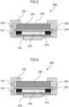
- FIG. 5 is a schematic diagram illustrating a coin cell.
- FIG. 6 is a schematic diagram illustrating another coin cell.
- a coin cell 600 in the third embodiment includes a laminated structure in which a negative electrode structure 610 and a positive electrode structure 620 are laminated with a separator 660 interposed therebetween.
- the laminated structure is restrained by a coin cell type restraint tool 630.
- An insulating O-ring (not illustrated) is placed between the coin cell type restraint tool 630 and a metal mesh 680, and insulation between the restraint tool 630 and the positive electrode structure 620 is secured.
- the air battery is named in the sense that oxygen in the air serves as the positive electrode active material of the battery, the supply of at least 21% of oxygen which is the oxygen concentration in the air is required. However, a higher concentration of oxygen is preferred in order to reduce the influence of diffusion control, and the air battery can exhibit the highest characteristics by supplying pure oxygen.
- the negative electrode structure 610 may be a usually used negative electrode structure.
- the negative electrode structure include a structure having a current collector 635 and a metal layer 640 containing an alkali metal and/or an alkaline earth metal wherein the metal layer 640 is provided on the current collector 635.
- the metal layer 640 can typically be a layer made of lithium metal.
- the positive electrode structure 620 includes a porous carbon structure 690 described in the first embodiment wherein the porous carbon structure 690 is in mechanical and electrical contact with the metal-containing mesh (metal mesh) 680 that serves function as both a flow path through which air or oxygen passes and a current collector.
- the metal-containing mesh metal mesh
- a positive electrode structure 621 includes only the porous carbon structure 690 described in the first embodiment.
- the difference between the coin cell 600 and the coin cell 601 is only the presence or absence of the metal mesh 680.
- An insulating O-ring (not illustrated) is placed between the coin cell type restraint tool 630 and the porous carbon structure 690, and insulation between the restraint tool 630 and the positive electrode structure 621 is secured.
- the positive electrode structure 620 including the metal mesh 680 increases electroconductivity and sufficiently secures the flow path for air or oxygen, this is a structure suitable for high output.
- the positive electrode structure 621 consisting only of the porous carbon structure 690 does not include a metal mesh as a current collector, this is a structure which provides a high weight energy density of the battery, has a simple structure, is manufactured with the reduced number of steps, and can perform efficient manufacture.
- the porous carbon structure 690 is a self-supporting body having sufficient rigidity, the porous carbon structure 690 can even alone serve as the positive electrode structure 621.
- a groove (not illustrated) be formed in the porous carbon structure 690 to secure an additional flow path through which air or oxygen passes. Since the porous carbon structure 690 of the present invention has sufficient strength, it is possible to provide a groove for the air or oxygen flow.
- the width of the groove can be, for example, 0.1 mm or more and 3 mm or less. When the width of the groove is less than 0.1 mm, the air or oxygen flow is reduced. Even when the width of the groove is more than 3 mm, there is no large difference in the air or oxygen flow, but the strength of the porous carbon structure 690 becomes lower, and the porous carbon structure 690 is easily broken. It is preferred that a plurality of grooves be formed, and it is also desired that the grooves be formed in a grid pattern.
- the separator 660 is placed between the negative electrode structure 610 and the positive electrode structure 620.
- a spacer 650 is formed between the separator 660 covering the metal layer 640.
- a space 670 is formed between the metal layer 640, the spacer 650, and the separator 660, and the space 670 is filled with an electrolytic solution.
- the negative electrode structure 610 is prepared.
- the negative electrode structure 610 is manufactured and prepared, for example, as follows.
- a disk-shaped metal layer 640 made of lithium or the like is laminated wherein the disk-shaped metal layer 640 is concentric with the current collector 635 and has a diameter smaller than that of the current collector 635, and then a columnar spacer 650 is pressed on the current collector 635 to obtain the negative electrode structure 610.
- examples of the spacer 650 material include metal oxides, metal nitrides, and metal oxynitrides having insulating properties.
- examples thereof include inorganic materials selected from the group consisting of Al 2 O 3 , Ta 2 O 5 , TiO 2 , ZnO, ZrO, SiO 2 , B 2 O 3 , P 2 O 5 , GeO 2 , Li 2 O, Na 2 O, K 2 O, MgO, CaO, SrO, BaO, Si 3 N 4 , AlN, and AlO x N 1-x (0 ⁇ x ⁇ 1).
- particularly Al 2 O 3 and SiO 2 are easily available and have characteristics of excellent processability.
- the spacer 650 may be made of an organic material selected from the group consisting of a polyolefin-based resin, a polyester-based resin, a polyimide-based resin, and a polyether ether ketone (PEEK)-based resin.
- the polyolefin-based resin is preferably polyethylene and/or polypropylene.
- the polyester-based resin is preferably selected from the group consisting of polyethylene terephthalate (PET), polybutylene terephthalate (PBT), polyethylene naphthalate (PEN), and polytributylene terephthalate (PTT). These resins are easily available and have excellent processability.
- the separator 660 is prepared and pressed on the spacer 650.
- the material applied to the separator 660 is any inorganic material, organic material, or metal material which can pass alkali metal ions and/or alkaline earth metal ions, is an insulating material having a porous structure, and is not reactive with the metal layer 640 and an electrolytic solution.
- the separator 660 is selected from the group consisting of the following: a porous film made of a synthetic resin such as polyethylene, polypropylene, or polyolefin; glass fibers; and a nonwoven fabric.
- the separator 660 is filled with an electrolytic solution.
- the space 670 is also preferably filled with the electrolytic solution.
- lithium salt When a lithium salt is used as an alkali metal salt and/or an alkaline earth metal salt in a non-aqueous electrolytic solution, examples of the lithium salt include LiPF 6 , LiBF 4 , LiSbF 6 , LiSiF 6 , LiAsF 6 , LiN(SO 2 C 2 F 5 ) 2 , Li(FSO 2 ) 2 N, LiCF 3 SO 3 (LiTfO), Li(CF 3 SO 2 ) 2 N(LiTFSI), LiC 4 F 9 SO 3 , LiClO 4 , LiAlO 2 , LiAlCl 4 , and LiB(C 2 O 4 ) 2 .
- LiPF 6 LiBF 4 , LiSbF 6 , LiSiF 6 , LiAsF 6 , LiN(SO 2 C 2 F 5 ) 2 , Li(FSO 2 ) 2 N, LiCF 3 SO 3 (LiTfO), Li(CF 3 SO 2 ) 2 N(LiTFS
- the non-aqueous solvent is selected from the group consisting of glymes (monoglyme, diglyme, triglyme, and tetraglyme), methyl butyl ether, diethyl ether, ethyl butyl ether, dibutyl ether, polyethylene glycol dimethyl ether, tetraethylene glycol dimethyl ether, cyclohexanone, dioxane, dimethoxyethane, 2-methyltetrahydrofuran, 2,2-dimethyltetrahydrofuran, 2,5-dimethyltetrahydrofuran, tetrahydrofuran, methyl acetate, ethyl acetate, n-propyl acetate, dimethyl acetate, methyl propionate, ethyl propionate, methyl formate, ethyl formate, dimethyl carbonate, diethyl carbonate, ethyl methyl
- the positive electrode structure 620 placing a metal mesh on the porous carbon structure 690 produced by the manufacturing method described in the first embodiment is prepared.
- Examples of the metal mesh 680 include a mesh containing a metal selected from the group of copper (Cu), tungsten (W), aluminum (Al), nickel (Ni), titanium (Ti), gold (Au), silver (Ag), platinum (Pt), and palladium (Pd). That is, examples of the metal mesh 680 include meshes containing a monometal selected from the above group, an alloy containing a metal selected from the above group, or a compound of a metal selected from the above group with carbon (C), nitrogen (N), or the like.
- the mesh can have a thickness of 0.2 mm and an aperture of 1 mm, for example.
- the positive electrode structure 620 is stuck to the negative electrode structure 610 filled with the electrolytic solution via the separator 660 interposed therebetween, and the resulting product is restrained by the coin cell type restraint tool 630 to obtain the coin cell 600.
- the mounting is preferably performed under dry air, for example, under dry air having a dew point temperature of -50°C or less.
- the coin cell 600 that operates as an air battery is manufactured.
- the positive electrode structure 620 to be prepared is required to be merely replaced with only the porous carbon structure 690 in the above-mentioned steps.
- the coin cells 600 and 601 becomes an air battery which is capable of being reduced in size and weight as well as which is suitable for increasing the capacity.
- the positive electrode structure 690 using the porous carbon structure described in the first embodiment has high air or oxygen permeability, is capable of taking in a large amount of oxygen, and further has both of high ion transport efficiency and a wide reaction field, its structure is a simple structure capable of being reduced in size which is the porous carbon structure alone or the porous carbon structure with a metal mesh placed thereon.
- FIG. 7 is a schematic diagram illustrating a cross-sectional structure of the air battery.
- FIG. 7 is a schematic diagram illustrating a laminated metal battery (air battery).
- An air battery 500 in the fourth embodiment has a laminated structure in which a positive electrode structure 510 and a negative electrode structure 100 are laminated via a separator 540 interposed therebetween.
- the number of laminated layers may be one or more pairs, and there is no particular upper limit on the number of the pairs.
- one pair is formed from one positive electrode structure 510 and one negative electrode structure 100, and this is defined as one unit.
- the negative electrode structure 100 has a configuration in which the negative electrode structures 610 described in the third embodiment are placed above and below a negative electrode current collector electrode 520 interposed therebetween, and the positive electrode structure 510 also has a configuration in which the porous carbon structures 690 described in the first embodiment are placed above and below a positive electrode current collector electrode 525 interposed therebetween wherein the positive electrode current collector electrode 525 also serves as a flow path for air or oxygen.
- the formation of a battery capable of providing a larger capacity by such a simple laminated structure is also characteristics peculiar to a porous carbon structure positive electrode having self-supporting ability.
- Examples of the negative electrode current collector electrode 520 include an electrode containing a metal selected from the group of copper (Cu), tungsten (W), nickel (Ni), titanium (Ti), gold (Au), silver (Ag), platinum (Pt), and palladium (Pd).
- Examples of the positive electrode current collector electrode 525 include an electrode containing a metal selected from the group of stainless steel (SUS), tungsten (W), aluminum (Al), nickel (Ni), titanium (Ti), gold (Au), silver (Ag), platinum (Pt), and palladium (Pd).
- examples of the current collector electrodes 520 and 525 include electrodes containing a simple metal selected from this group, an alloy containing a metal selected from this group, or a compound of a metal selected from this group with carbon (C), nitrogen (N), or the like. Since the positive electrode current collector electrode 525 also serves as an oxygen flow path, it is necessary to use a porous metal such as a mesh, a grid, or a sponge.
- the laminated structure is housed in a housing container (not illustrated).
- the air battery 500 becomes an air battery which is capable of being reduced in size and weight as well as which is suitable for increasing the capacity.
- the positive electrode structure 510 using the porous carbon structure described in the first embodiment has high air or oxygen permeability, is capable of taking in a large amount of oxygen, and further has both of high ion transport efficiency and a wide reaction field, its structure is a simple structure capable of being reduced in size which is the porous carbon structure alone or the porous carbon structure with a metal mesh placed thereon.
- the air battery using the positive electrode structure 510 of the present invention has been described in detail with reference to FIG. 7 , but the positive electrode structure 510 of the present invention can be applied to any metal battery without limitation to the air battery.
- Porous carbon structure Nos. 2, 3, 5 to 8, 10 and 15 are porous carbon structure samples of the present invention produced in the examples, and the samples referred to as Porous carbon structure Nos. 1, 4, 9, 11 to 14 and 16 to 25 are comparative samples (comparative examples).
- Example 1A the preparation of porous carbon structure samples of the present invention (Porous carbon structure Nos. 2, 3, 5 to 8, and 10) and comparative samples (Porous carbon structure Nos. 1, 4 and 9), and properties of the produced porous carbon structure samples and the comparative sample are described.
- a mixture slurry was prepared using the following: 65 wt% of porous carbon particles; 12 wt% of carbon fibers; 23 wt% of a binding polymer material; and a solvent containing N-methylpyrrolidone to uniformly disperse the above-mentioned components (step S1 in FIG. 4 ).
- Ketjen Black (registered trademark) (EC600J manufactured by LION SPECIALTY CHEMICALS CO., LTD.) was used as the porous carbon particles. Properties of Ketjen Black EC600J are shown in Table 1.
- carbon fibers having an average fiber diameter of 6 ⁇ m and an average length of 3 mm were used.
- PAN polyacrylonitrile
- Table 1 Properties of porous carbon particles used herein Name Volume of pores having diameter of 1 nm or more and 1,000 nm or less (BJH method) Volume of pores having diameter of 1 nm or more and 200 nm or less (BJH method) Volume of pores having diameter of 200 nm or more and 1,000 nm or less (BJH method) BET specific surface area t-Plot external specific surface area t-Plot micropore specific surface area (cm 3 /g) (cm 3 /g) (cm 3 /g) (m 2 /g) (m 2 /g) (m 2 /g) Ketjen Black EC600J 3.6 2.6 1.0 1328 1130 198 Black pearls 3.2 2.8 0.4 1547 486 1061 Vulcan XC72 1.0 0.8 0.2 227 117 110
- the mixture slurry was molded into a sheet having a uniform thickness by means of a wet film forming method using a doctor blade (step S2 in FIG. 4 ).
- three types of molded sheets each of which has a thickness of 300 ⁇ m, 500 ⁇ m, or 600 ⁇ m were produced.
- the non-solvent induced phase separation method is a method in which a polymer solution is immersed in a non-solvent to phase-separate and precipitate a polymer.
- Example 1A the molded sheet in a state where the above Ketjen Black (registered trademark) as porous carbon particles and the above carbon fibers were dispersed in an N-methylpyrrolidone solution of polyacrylonitrile (PAN) as a binding polymer material was immersed in methanol as a non-solvent (poor solvent) to phase-separate and precipitate polyacrylonitrile (PAN) in a state of bonding the above Ketjen Black (registered trademark) with the above carbon fibers, thereby producing a porous film containing the above Ketjen Black (registered trademark) as a skeleton and also containing the above carbon fibers.
- PAN polyacrylonitrile
- PAN polyacrylonitrile
- step S4 in FIG. 4 a drying step at 50 to 80°C for 10 hours or more was performed to remove the volatile solvent from the sample, and subsequently an infusibilization heat treatment (step S5 in FIG. 4 ) was performed at 320°C for 3 hours in the air.
- the carbonization treatment was performed using a box type furnace manufactured by DENKEN-HIGHDENTAL Co., Ltd., and the temperature rise speed was 10°C/min in all the following cases: a case of performing the carbonization treatment (oxidation treatment) in an oxidizing gas atmosphere; a case of performing the carbonization treatment in an inert gas atmosphere; and a case of performing the carbonization treatment in an oxidizing gas atmosphere, and subsequently in an inert gas atmosphere.
- the oxidizing gas was a mixed gas of oxygen and nitrogen.
- the inert gas was nitrogen gas.
- Porous carbon structure Nos. 1 and 4 in Table 2 only carbonization was performed while flowing nitrogen at 800 mL/min without performing the oxidation treatment.
- carbonization was performed by the following: raising the temperature to the oxidation temperature shown in Table 2 while flowing a gas having an oxygen concentration shown in Table 2 at 800 mL/min; switching the gas to nitrogen at the temperature, subsequently raising the temperature to 1050°C in nitrogen, and holding the sample for 3 hours; and then cooling the sample to room temperature.
- carbonization was performed by the following: raising the temperature to 1050°C of the oxidation temperature shown in Table 2 while flowing a gas having an oxygen concentration shown in Table 2 at 800 mL/min; holding the sample for 2 hours, subsequently switching the gas to nitrogen, and holding the sample for 1 hour; and then cooling the sample to room temperature.
- FIG. 8 is a SEM image of the sample of Porous carbon structure No. 5.
- FIG. 9 is an enlarged view of the SEM image in FIG. 8 .
- FIGS. 8 and 9 it has been found that the method of the present invention ( FIG. 4 ) provides a porous carbon structure having a skeleton 10 containing carbon and a large number of pores 11 and 12.
- FIG. 8 shows the pores 12 corresponding to "pores having a diameter of 200 nm or more and 10,000 nm or less”
- FIG. 9 shows the pores 11 corresponding to "pores having a diameter of 1 nm or more and 1,000 nm or less”.
- the pore volume was determined by the BJH method from an adsorption isotherm obtained by the nitrogen adsorption method using 3Flex (manufactured by Micromeritics Instrument Corp.).
- the pore volume was determined by the BJH method from an adsorption isotherm obtained by the nitrogen adsorption method using 3Flex (manufactured by Micromeritics Instrument Corp.).
- the pore volume of pores having a diameter in the range of 10 nm to 200,000 nm (0.01 ⁇ m to 200 ⁇ m) was measured by means of the mercury intrusion method using AutoPore IV (manufactured by Micromeritics Instrument Corp.), and a value of the pore volume of pores having a pore diameter of 1 ⁇ m to 200 ⁇ m was used.
- the BET specific surface area was determined according to the BET method from an adsorption isotherm obtained by the nitrogen adsorption method using 3Flex (manufactured by Micromeritics Instrument Corp.).
- the t-plot external specific surface area was determined by the t-plot method from a graph of an adsorption isotherm, which was obtained by the nitrogen adsorption method using 3Flex (manufactured by Micromeritics Instrument Corp.), and in which the layer thickness of adsorbed nitrogen was plotted on the horizontal axis, and the amount of adsorbed nitrogen was plotted on the vertical axis.
- the t-plot micropore specific surface area is defined as a value obtained by subtracting the t-plot external specific surface area from the specific surface area determined by the BET method.
- the apparent density was determined by dividing the weight of the porous carbon structure by the volume of the porous carbon structure.
- the porosity was determined by the following calculation. (1 - apparent density of porous carbon structure/true density of constituent material of porous carbon structure) ⁇ 100
- the pore volume of pores having a diameter in the range of 10 nm to 200,000 nm (0.01 ⁇ m to 200 ⁇ m) was measured by means of the mercury intrusion method using AutoPore IV (manufactured by Micromeritics Instrument Corp.), and a value of the pore volume of pores having a pore diameter of 200 nm to 10,000 nm was used.
- a sample was weighed, and burned in an argon/oxygen mixed gas in a combustion tube of an analyzer (AQF-2100H, GA-210 (manufactured by Mitsubishi Chemical Corporation) was used).
- a gas generated by the burning was made to be absorbed in an aqueous hydrogen peroxide solution, and then a part of the solution having absorbed the gas was analyzed using ion chromatography ICS-1600 manufactured by Dionex Corporation.
- Porous carbon structure Nos. 2, 3, 5 to 8, and 10 a pore volume of pores having a diameter of 1 nm or more and 1,000 nm or less satisfies the range of 4.1 cm 3 /g or more and 9.0 cm 3 /g or less, which is in the range of 4.0 cm 3 /g or more and 10.0 cm 3 /g or less, and a pore volume of pores having a diameter of 1 nm or more and 200 nm or less satisfies the range of 2.4 cm 3 /g or more and 6.0 cm 3 /g, which is in the range of 2.2 cm 3 /g or more and 7.0 cm 3 /g or less.
- the pore volumes were larger than those values of Ketjen Black (registered trademark) as a raw material shown in Table 1.
- Ketjen Black registered trademark
- Table 1 the pore volume in each sample of Porous carbon structure Nos. 2, 3, 5 to 8, and 10 was 1.02 times or more the pore volume in Ketjen Black (registered trademark), and it has been confirmed that the carbonization treatment step was sufficiently performed.
- PAN polyacrylonitrile
- Ketjen Black registered trademark
- a carbonized product of PAN were mostly burned off by the oxidation treatment, so that the surface of Ketjen Black (registered trademark) was able to be exposed; and further a part of the particle surface of Ketjen Black (registered trademark) was oxidized and burned off.
- PAN existing at the portion binding Ketjen Black (registered trademark) particles to each other is not burned off due to difficulty of entry of oxygen, and thus remains as carbonized, thereby securing the self-supporting ability and strength of the porous carbon structure.
- Example 2A a CR2032 type coin cell 601 ( FIG. 6 ) was produced using each sample of Porous carbon structure Nos. 1 to 8 and 10 manufactured (produced) in Example 1A for a positive electrode structure 690 ( FIG. 6 ), and battery characteristics of the coin cell were evaluated.
- the sample of Porous carbon structure No. 9 subjected to an oxidation treatment at an oxygen concentration of 5% up to 1050°C was not subjected to battery evaluation as a positive electrode. This is because the sample of Porous carbon structure No. 9 was not in a state capable of performing the battery evaluation due to its low strength and brittleness.
- a coin cell was manufactured as follows. In a dry room (in dry air) having a dew point temperature of -50°C or less, a positive electrode structure obtained by cutting each of Porous carbon structure Nos. 1 to 8 and 10 into a piece having a diameter ( ⁇ ) of 16 mm, metal lithium (which has a diameter ( ⁇ ) of 16 mm and a thickness of 0.2 mm) as a negative electrode structure, and glass fiber paper (Whatman (registered trademark), GF/A) as a separator, which was immersed in the 1 M-tetraethylene glycol dimethyl ether solution of LiTFS (lithium trifluoromethanesulfonate) as an electrolytic solution, were packaged in a coin cell case (CR2032 type).
- a positive electrode structure obtained by cutting each of Porous carbon structure Nos. 1 to 8 and 10 into a piece having a diameter ( ⁇ ) of 16 mm, metal lithium (which has a diameter ( ⁇ ) of 16 mm and a thickness of 0.2 mm) as a
- discharge was also performed under the conditions of high-speed current densities of 0.6 mA/cm 2 and 0.8 mA/cm 2 in addition to the condition of a current density of 0.4 mA/cm 2 , and the discharge capacity per weight of the positive electrode was calculated by dividing the obtained discharge capacity by the weight of the porous carbon structure used as the positive electrode by taking the time point when the voltage decreased to 2.3 V as the discharge end point.
- each sample of Porous carbon structure Nos. 2, 3, 5 to 8, and 10 of the present invention obtained by an oxidation treatment in an oxidizing gas atmosphere as the carbonization treatment in the carbonization treatment step (step S4) not only exhibit a higher discharge capacity in discharge at a current density of 0.4 mA/cm 2 but also exhibit a higher discharge capacity in discharge at high-speed current densities of 0.6 mA/cm 2 and 0.8 mA/cm 2 , compared with coin cells using, as a positive electrode structure, each comparative sample of Porous carbon structure Nos. 1 and 4 obtained by carbonization only with nitrogen gas without being subjected to the oxidation treatment.
- Example 1B the preparation of a porous carbon structure sample of the present invention (Porous carbon structure No. 15) and comparative samples (Porous carbon structure Nos. 11 to 14 and 16 to 25), and properties of the produced porous carbon structure samples and the comparative samples are described.
- a mixture slurry was prepared using the following: 65 wt% of porous carbon particles; 10 wt% of carbon fibers; 25 wt% of a binding polymer material; and a solvent containing N-methylpyrrolidone to uniformly disperse the above-mentioned components (step S1 in FIG. 4 ).
- porous carbon particles carbon black containing 65 wt% of Ketjen Black (registered trademark) was used.
- carbon fibers carbon fibers having an average fiber diameter of 7 ⁇ m and an average length of 3 mm were used.
- the binding polymer material polyacrylonitrile (PAN) was used.
- the mixture slurry was molded into a sheet having a uniform thickness by means of a wet film forming method using a doctor blade (step S2 in FIG. 4 ). After molding the mixture slurry, the molded sample was immersed in water (a poor solvent) by means of a non-solvent induced phase separation method to form the molded sample into a porous film.
- step S4 in FIG. 4 a drying step at 50 to 80°C for 10 hours or more was performed to remove the volatile solvent from the sample, and subsequently an infusibilization heat treatment (step S5 in FIG. 4 ) was performed at 280°C for 3 hours in the air.
- step S6 in FIG. 4 firing was performed at 1000°C for 3 hours in a firing furnace under a nitrogen gas atmosphere after vacuum replacement to produce a porous carbon structure sample having a length of 140 mm, a width of 100 mm, and a thickness of 510 ⁇ m (step S7 in FIG. 4 ).
- the producing (manufacturing) conditions of the sample of Porous carbon structure No. 11 are as shown in Table 2.
- the content of Ketjen Black was 79 wt%, and the sample had a thickness of 510 ⁇ m as shown in Table 2, a basis weight of 10.8 mg/cm 2 , a BET specific surface area of 646 m 2 /g as shown in Table 3, a t-plot external specific surface area of 540 m 2 /g as shown in Table 3, and a total t-plot external specific surface area ratio (SA ratio) of 84% as shown in Table 3.
- SA ratio total t-plot external specific surface area ratio
- the sample had a porosity of 89.9% as shown in Table 3.
- FIG. 10 A secondary scanning electron microscope image of the obtained porous carbon structure is shown in FIG. 10 .
- the porous carbon structure had a spongelike structure with pores, it exhibited self-supporting strength.
- Porous carbon structure No. 12 was produced in the same manner as the preparation of Porous carbon structure No. 11 except that methanol was used as a poor solvent in the non-solvent induced phase separation method.
- the specific producing (manufacturing) conditions are as shown in Table 2.
- the content of Ketjen Black was 79 wt%, and the sample had a thickness of 470 ⁇ m as shown in Table 2, a basis weight of 7.9 mg/cm 2 , a BET specific surface area of 646 m 2 /g as shown in Table 3, a t-plot external specific surface area of 533 m 2 /g as shown in Table 3, and a total t-plot external specific surface area ratio (SA ratio) of 83% as shown in Table 3. Also, the sample had a porosity of 90% as shown in Table 3.
- the sample of Porous carbon structure No. 13 was produced in the same manner as the preparation of the sample of Porous carbon structure No. 11 except that ethanol was used as a poor solvent in the non-solvent induced phase separation method.
- the specific producing (manufacturing) conditions are as shown in Table 2.
- the content of Ketjen Black was 79 wt%, and the sample had a thickness of 542 ⁇ m as shown in Table 2, a basis weight of 9.4 mg/cm 2 , a BET specific surface area of 709 m 2 /g as shown in Table 3, a t-plot external specific surface area of 567 m 2 /g as shown in Table 3, and a total t-plot external specific surface area ratio (SA ratio) of 80% as shown in Table 3.
- SA ratio total t-plot external specific surface area ratio
- the sample had a porosity of 91% as shown in Table 3.
- Each sample of Porous carbon structure Nos. 14 and 15 was produced in the same manner as the preparation of the sample of Porous carbon structure No. 11 except for the following: as for the sample of Porous carbon structure No. 14, a mixture slurry having a composition (mixture composition) of 70 wt% of Ketjen Black, 10 wt% of carbon fibers, and 20 wt% of PAN was prepared and used; and as for the sample of Porous carbon structure No. 15, a mixture slurry having a composition (mixture composition) of 85 wt% of Ketjen Black, 10 wt% of carbon fibers, and 5 wt% of PAN was prepared and used.
- the specific producing (manufacturing) conditions are as shown in Table 2.
- the sample had a thickness of 220 ⁇ m as shown in Table 2, a basis weight of 3.7 mg/cm 2 , a BET specific surface area of 931 m 2 /g as shown in Table 3, a t-plot external specific surface area of 898 m 2 /g as shown in Table 3, and a total t-plot external specific surface area ratio (SA ratio) of 96% as shown in Table 3. Also, the sample had a porosity of 93% as shown in Table 3.
- the sample had a thickness of 245 ⁇ m as shown in Table 2, a basis weight of 4.0 mg/cm 2 , a BET specific surface area of 1,111 m 2 /g as shown in Table 3, a t-plot external specific surface area of 1,072 m 2 /g as shown in Table 3, and a total t-plot external specific surface area ratio (SA ratio) of 96% as shown in Table 3. Also, the sample had a porosity of 93% as shown in Table 3.
- the sample of Porous carbon structure No. 15 has a t-plot external specific surface area of 1,072 m 2 /g which satisfies the above-mentioned condition (a), a pore volume of pores having a diameter of 1 nm or more and 200 nm or less of 3.0 cm 3 /g which satisfies the above-mentioned condition (b), a pore volume of pores having a diameter of 1 nm or more and 1,000 nm or less of 4.0 cm 3 /g which satisfies the above-mentioned condition (c), an overall porosity of 93.0% which satisfies the above-mentioned condition (d), and a pore volume of pores having a diameter of 200 nm or more and 10,000 nm or less of 2.7 cm 3 /g which satisfies the above-mentioned condition (e), and thus satisfies all of the above-mentioned condition (a), a pore volume of pores
- the sample of Porous carbon structure No. 16 was produced in the same manner as the preparation of the sample of Porous carbon structure No. 11 except for the following: BLACK PEARLS (registered trademark) 2000 (manufactured by Cabot Corporation) was used as porous carbon particles; and a mixture slurry having a composition (mixture composition) of 68 wt% of BLACK PEARLS (registered trademark), 9 wt% of carbon fibers, and 23 wt% of PAN was prepared and used.
- the specific producing (manufacturing) conditions are as shown in Table 2.
- the sample had a thickness of 170 ⁇ m as shown in Table 2, a basis weight of 4.3 mg/cm 2 , a BET specific surface area of 930 m 2 /g as shown in Table 3, a t-plot external specific surface area of 320 m 2 /g as shown in Table 3, and a total t-plot external specific surface area ratio (SA ratio) of 34% as shown in Table 3. Also, the sample had a porosity of 88% as shown in Table 3.
- the sample of Porous carbon structure No. 17 was produced in the same manner as the preparation of the sample of Porous carbon structure No. 11 except that a gas diffusion layer sheet (TGP-H-060 manufactured by Toray Industries, Inc.) made of carbon fibers was used as a sheet obtained by molding a mixture slurry into a sheet having a uniform thickness by means of a wet film forming method using a doctor blade.
- the specific producing (manufacturing) conditions are as shown in Table 2.
- the sample had a thickness of 190 ⁇ m as shown in Table 2, a basis weight of 8.1 mg/cm 2 , a small BET specific surface area of 80 m 2 /g as shown in Table 3, and a small a t-plot external specific surface area of 80 m 2 /g as shown in Table 3. Also, the sample had a low porosity of 78% as shown in Table 3.
- the sample of Porous carbon structure No. 18 was produced in the same manner as the preparation of the sample of Porous carbon structure No. 11 except that an activated carbon fiber woven fabric (CL1420 manufactured by FUTAMURA CHEMICAL CO., LTD.) was used as a sheet obtained by molding a mixture slurry into a sheet having a uniform thickness by means of a wet film forming method using a doctor blade.
- the specific producing (manufacturing) conditions are as shown in Table 2.
- the sample had a thickness of 283 ⁇ m as shown in Table 2, a basis weight of 7.9 mg/cm 2 , a large BET specific surface area of 1,994 m 2 /g as shown in Table 3, a small t-plot external specific surface area of 114 m 2 /g as shown in Table 3, and a low total t-plot external specific surface area ratio (SA ratio) of 5.7% as shown in Table 3.
- SA ratio total t-plot external specific surface area ratio
- Each sample of Porous carbon structure Nos. 19 and 20 was produced in the same manner as the preparation of Porous carbon structure No. 11 except for the following: as for the sample of Porous carbon structure No. 19, a mixture slurry having a composition (mixture composition) of 20 wt% of Ketjen Black, 10 wt% of carbon fibers, and 70 wt% of PAN was prepared and used; and as for the sample of Porous carbon structure No. 20, a mixture slurry having a composition (mixture composition) of 30 wt% of Ketjen Black, 10 wt% of carbon fibers, and 60 wt% of PAN were prepared and used.
- the specific producing (manufacturing) conditions are as shown in Table 2.
- the sample had a thickness of 142 ⁇ m as shown in Table 2, a basis weight of 2.8 mg/cm 2 , a BET specific surface area of 34 m 2 /g as shown in Table 3, a t-plot external specific surface area of 22 m 2 /g as shown in Table 3, and a total t-plot external specific surface area ratio (SA ratio) of 65% as shown in Table 3.
- SA ratio total t-plot external specific surface area ratio
- the sample had a porosity of 91.4% as shown in Table 3.
- the sample had a small BET specific surface area and a small t-plot external specific surface area.
- the sample had a thickness of 170 ⁇ m as shown in Table 2, a basis weight of 3.8 mg/cm 2 , a BET specific surface area of 79 m 2 /g as shown in Table 3, a t-plot external specific surface area of 39 m 2 /g as shown in Table 3, and a total t-plot external specific surface area ratio (SA ratio) of 49% as shown in Table 3. Also, the sample had a porosity of 90.1% as shown in Table 3.
- each of Porous carbon structure Nos. 19 and 20 had a small BET specific surface area and a small t-plot external specific surface area.
- the sample of Porous carbon structure No. 21 was produced in the same manner as the preparation of Porous carbon structure No. 11 except for the following: VULCAN (registered trademark) XC-72 (manufactured by Cabot Corporation) was used as porous carbon particles; and a mixture slurry having a composition (mixture composition) of 68 wt% of VULCAN (registered trademark) XC-72, 9 wt% of carbon fibers, and 23 wt% of PAN was prepared and used.
- the specific producing (manufacturing) conditions are as shown in Table 2.
- the sample had a thickness of 216 ⁇ m as shown in Table 2, a basis weight of 7.1 mg/cm 2 , a BET specific surface area of 153 m 2 /g as shown in Table 3, a t-plot external specific surface area of 66 m 2 /g as shown in Table 3, and a total t-plot external specific surface area ratio (SA ratio) of 43% as shown in Table 3. Also, the sample had a porosity of 85% as shown in Table 3.
- a composition (mixture composition) of a mixture slurry prepared therein 65 wt% of Ketjen Black (registered trademark) and 35 wt% of PTFE (manufactured by DAIKIN INDUSTRIES, LTD.) as a binder were used, and the solution of the mixture slurry was prepared by dispersing the above components in a water solvent.
- PTFE means polytetrafluoroethylene.
- an activated carbon fiber woven fabric (CL1420 manufactured by FUTAMURA CHEMICAL CO., LTD.) was used as a supporting material, and on this base film, the above-mentioned water-dispersed mixture slurry was molded into a sheet having a uniform thickness by means of a wet film forming method using a doctor blade, thereby producing a sheet integrated with the activated carbon fiber supporting material.
- the volatile solvent was removed from the produced sheet, and the sheet was dried to produce a porous carbon film integrated with the activated carbon fiber woven fabric.
- the product was used as a porous carbon structure.
- the sample had a thickness of 354 ⁇ m as shown in Table 2, a basis weight of 12.6 mg/cm 2 , a BET specific surface area of 1,434 m 2 /g as shown in Table 3, a t-plot external specific surface area of 291 m 2 /g as shown in Table 3, and a total t-plot external specific surface area ratio (SA ratio) of 20% as shown in Table 3. Also, the sample had a porosity of 81% as shown in Table 3.
- the sample had a thickness of 354 ⁇ m as shown in Table 2, a basis weight of 12.6 mg/cm 2 , a BET specific surface area of 1,434 m 2 /g as shown in Table 3, a t-plot external specific surface area of 1,142 m 2 /g as shown in Table 3, and a total t-plot external specific surface area ratio (SA ratio) of 20% as shown in Table 3. Also, the sample had a porosity of 81% as shown in Table 3.
- the mixture slurry was molded into a sheet having a uniform thickness by means of a wet film forming method using a doctor blade.
- the volatile solvent was removed from the produced sheet and the sheet was dried, and as a result, the film-like product was cracked and did not form a self-supporting film.
- Porous carbon structure No. 24 was produced in the same manner as the preparation of Porous carbon structure No. 23 except that a molded sheet was produced by pressing at 10 MPa when forming the sheet from a mixture slurry. The dried film-like product was cracked and did not form a self-supporting film.
- the sample of Porous carbon structure No. 25 was produced in the same manner as the preparation of Porous carbon structure No. 23 except that a mixture slurry prepared had a composition (mixture composition) of 95 wt% of Ketjen Black (registered trademark) and 5 wt% of PTFE (manufactured by DAIKIN INDUSTRIES, LTD.) as a binder.
- the dried film-like product was cracked and did not form a self-supporting film.
- Example 2B a CR2032 type coin cell 601 ( FIG. 6 ) was produced using each sample of Porous carbon structure Nos. 11 to 16 manufactured (produced) in Example 1B as a positive electrode structure 690 ( FIG. 6 ), and battery characteristics of the coin cell were evaluated.
- a CR2032 type coin cell 601 was similarly produced using each comparative sample of Porous carbon structure Nos. 17 to 22 as a positive electrode structure 690 ( FIG. 6 ), and battery characteristics of the coin cell were evaluated.
- Comparative samples of Porous carbon structure Nos. 23 to 25 were not subjected to battery evaluation. This is because these samples did not form a self-supporting film as described above, and were not in a state of being capable of battery evaluation as a positive electrode.
- a coin cell was manufactured as follows, similarly to the manufacture of the coin cell in Example 2A.
- a positive electrode structure obtained by cutting each of Porous carbon structure Nos. 11 to 16 into a piece having a diameter ( ⁇ ) of 16 mm, metal lithium (which has a diameter ( ⁇ ) of 16 mm and a thickness of 0.2 mm) as a negative electrode structure, and glass fiber paper (Whatman (registered trademark), GF/A) as a separator, which was immersed in a 1 M-tetraethylene glycol dimethyl ether solution of LiTFS (lithium trifluoromethanesulfonate) as an electrolytic solution, were mounted in a coin cell case (CR2032 type). In this way, an air battery (lithium-air battery) was produced.
- LiTFS lithium trifluoromethanesulfonate
- the test was performed at a discharge current density of 0.4 mA/cm 2 under a pure oxygen atmosphere, and the discharge capacity (mAh/g) per weight of the positive electrode was calculated by dividing the obtained discharge capacity by the weight of the porous carbon structure used as the positive electrode by taking the time point when the voltage decreased to 2.3 V as the discharge end point.
- the test results are shown in Table 4 together with the test results of each coin cell (lithium-air batterie) manufactured (produced) in Example 2A, each of which uses one of Porous carbon structure Nos. 1 to 8 and 10 as a positive electrode.
- Example 2B some of the lithium-air batteries manufactured (produced) in Example 2B were also tested, similarly to the coin cells (lithium-air batteries) manufactured (produced) in Example 2A, at higher speed discharge current densities of 0.6 mA/cm 2 and 0.8 mA/cm 2 in addition to a discharge current density of 0.4 mA/cm 2 .
- the porous carbon structure of the present invention which satisfies all of the above-mentioned conditions (a) to (e) does not require a current collector such as a metal mesh and alone serves as a positive electrode material for an air battery. It has also been shown that the air battery using the above porous carbon structure has high battery capacity and high-load characteristics which are generated by high air or oxygen diffusivity, high ion transport efficiency, and a wide reaction field, caused by the porous carbon structure.
- the porous carbon structure of the present invention is a porous carbon structure having an unprecedented high pore volume.
- Use of the porous carbon structure as a positive electrode of an air battery can provide an air battery having high battery capacity and high-load characteristics which are generated by high air or oxygen diffusivity, high ion transport efficiency, and a wide reaction field, caused by the porous carbon structure.
- the porous carbon structure has self-supporting ability with which the porous carbon structure can be used alone as a positive electrode material without using a current collector such as a metal mesh, it is possible to provide an air battery which is small in size and light in weight as well as which is suitable for increasing the capacity. Therefore, the present invention is expected to be preferably used in an air battery whose demand is expected to greatly expand in the future.
Landscapes
- Chemical & Material Sciences (AREA)
- Engineering & Computer Science (AREA)
- Manufacturing & Machinery (AREA)
- Ceramic Engineering (AREA)
- Chemical Kinetics & Catalysis (AREA)
- Electrochemistry (AREA)
- General Chemical & Material Sciences (AREA)
- Organic Chemistry (AREA)
- Materials Engineering (AREA)
- Structural Engineering (AREA)
- Inorganic Chemistry (AREA)
- Thermal Sciences (AREA)
- Physics & Mathematics (AREA)
- Composite Materials (AREA)
- Inert Electrodes (AREA)
- Hybrid Cells (AREA)
- Cell Electrode Carriers And Collectors (AREA)
- Porous Artificial Stone Or Porous Ceramic Products (AREA)
- Battery Electrode And Active Subsutance (AREA)
Applications Claiming Priority (3)
| Application Number | Priority Date | Filing Date | Title |
|---|---|---|---|
| JP2019096585 | 2019-05-23 | ||
| JP2020034769 | 2020-03-02 | ||
| PCT/JP2020/020143 WO2020235638A1 (ja) | 2019-05-23 | 2020-05-21 | 多孔炭素構造体、その製造方法、それを用いた正極材及びそれを用いた電池 |
Publications (3)
| Publication Number | Publication Date |
|---|---|
| EP3975322A1 EP3975322A1 (en) | 2022-03-30 |
| EP3975322A4 EP3975322A4 (en) | 2024-03-20 |
| EP3975322B1 true EP3975322B1 (en) | 2024-11-13 |
Family
ID=73459092
Family Applications (1)
| Application Number | Title | Priority Date | Filing Date |
|---|---|---|---|
| EP20809459.9A Active EP3975322B1 (en) | 2019-05-23 | 2020-05-21 | Porous carbon structure, manufacturing method therefor, positive electrode material using same, and battery using same |
Country Status (5)
| Country | Link |
|---|---|
| US (1) | US12272826B2 (https=) |
| EP (1) | EP3975322B1 (https=) |
| JP (1) | JP7177547B2 (https=) |
| CN (1) | CN113841284B (https=) |
| WO (1) | WO2020235638A1 (https=) |
Families Citing this family (6)
| Publication number | Priority date | Publication date | Assignee | Title |
|---|---|---|---|---|
| JP7648126B2 (ja) * | 2020-12-08 | 2025-03-18 | 国立研究開発法人物質・材料研究機構 | 空気電池用正極シート、および、それを用いた空気電池 |
| DE102021117025A1 (de) * | 2021-07-01 | 2023-01-05 | Nippon Kornmeyer Carbon Group Gmbh | Verfahren zur Herstellung von karbonisierten oder graphitierten Formteilen |
| JP7525116B2 (ja) * | 2021-11-26 | 2024-07-30 | 国立研究開発法人物質・材料研究機構 | 多孔炭素膜製造用組成物、及び多孔炭素膜製造用シート |
| JP7486129B2 (ja) * | 2021-11-26 | 2024-05-17 | 国立研究開発法人物質・材料研究機構 | 空気電池正極用の多孔炭素膜の製造方法、及びその方法で得られる多孔炭素膜を正極に用いた空気電池の製造方法 |
| JP2024092093A (ja) * | 2022-12-26 | 2024-07-08 | 国立研究開発法人物質・材料研究機構 | 炭素構造体、空気電池、及び炭素構造体の製造方法 |
| CN121794222A (zh) * | 2023-12-28 | 2026-04-03 | 株式会社3Dc | 碳材料、导电助剂、分散液、电极用组合物、电极用浆料、电极、锂离子电池及碳材料的制造方法 |
Family Cites Families (22)
| Publication number | Priority date | Publication date | Assignee | Title |
|---|---|---|---|---|
| GB1492262A (en) | 1975-05-07 | 1977-11-16 | Imp Metal Ind Kynoch Ltd | Titanium base alloy |
| WO2004112174A1 (ja) * | 2003-06-11 | 2004-12-23 | Matsushita Electric Industrial Co., Ltd. | 酸素還元用電極の製造方法ならびに酸素還元用電極及びそれを用いた電気化学素子 |
| US8142883B2 (en) * | 2005-09-29 | 2012-03-27 | Takashi Chida | Porous carbon sheet and process for production thereof |
| CN102044673B (zh) * | 2006-04-07 | 2012-11-21 | 三菱化学株式会社 | 锂二次电池正极材料用锂镍锰钴系复合氧化物粉体 |
| JP5481646B2 (ja) * | 2008-06-04 | 2014-04-23 | 清蔵 宮田 | 炭素触媒、燃料電池、蓄電装置 |
| US8481187B2 (en) * | 2009-09-10 | 2013-07-09 | Battelle Memorial Institute | High-energy metal air batteries |
| KR101232263B1 (ko) * | 2011-03-16 | 2013-02-12 | 한국과학기술연구원 | 리튬-공기 전지용 탄소계 양극 및 이의 제조 방법 |
| JP2012252995A (ja) * | 2011-05-10 | 2012-12-20 | Hitachi Ltd | 金属空気二次電池 |
| JP5852548B2 (ja) | 2012-06-12 | 2016-02-03 | トヨタ自動車株式会社 | 多孔質炭素及び金属空気電池 |
| CN105379000B (zh) * | 2013-07-17 | 2019-08-27 | 印制能源技术有限公司 | 能量储存装置 |
| JP2015026482A (ja) | 2013-07-25 | 2015-02-05 | 国立大学法人北海道大学 | 多孔質炭素材料及びその製造方法 |
| DE102013217882A1 (de) | 2013-09-06 | 2015-03-12 | Sgl Carbon Se | Elektrodensubstrat aus Kohlenstofffasern |
| JP2015076125A (ja) * | 2013-10-04 | 2015-04-20 | トヨタ自動車株式会社 | 多孔質炭素及び金属空気電池 |
| KR101556470B1 (ko) * | 2014-03-31 | 2015-10-02 | 연세대학교 산학협력단 | 중질유분의 분해반응을 이용한 탄소 구조체의 제조방법 |
| JP6436085B2 (ja) | 2014-07-15 | 2018-12-12 | 東レ株式会社 | 金属空気電池用電極材料 |
| KR101804005B1 (ko) * | 2014-10-17 | 2017-12-04 | 주식회사 엘지화학 | 리튬 공기 전지용 양극, 이의 제조방법 및 이를 포함하는 리튬 공기 전지 |
| CN107004866B (zh) * | 2014-12-26 | 2019-12-03 | 日本制铁株式会社 | 金属空气电池用电极 |
| JP6320333B2 (ja) * | 2015-03-20 | 2018-05-09 | 富士フイルム株式会社 | 複合体、複合体の製造方法及び燃料電池触媒 |
| WO2017104772A1 (ja) * | 2015-12-17 | 2017-06-22 | 日本ゼオン株式会社 | 繊維状炭素ナノ構造体分散液 |
| JP6814339B2 (ja) * | 2016-01-15 | 2021-01-20 | 日鉄ケミカル&マテリアル株式会社 | 触媒担体用炭素材料、固体高分子形燃料電池用触媒層、及び固体高分子形燃料電池 |
| TWI601689B (zh) * | 2016-02-01 | 2017-10-11 | 台灣奈米碳素股份有限公司 | 含氮之多孔性碳材料及其電容與製造方法 |
| JP2018133168A (ja) | 2017-02-14 | 2018-08-23 | パナソニックIpマネジメント株式会社 | リチウム空気電池及びその使用方法 |
-
2020
- 2020-05-21 EP EP20809459.9A patent/EP3975322B1/en active Active
- 2020-05-21 WO PCT/JP2020/020143 patent/WO2020235638A1/ja not_active Ceased
- 2020-05-21 JP JP2021520848A patent/JP7177547B2/ja active Active
- 2020-05-21 CN CN202080035651.8A patent/CN113841284B/zh active Active
- 2020-05-21 US US17/611,984 patent/US12272826B2/en active Active
Also Published As
| Publication number | Publication date |
|---|---|
| WO2020235638A1 (ja) | 2020-11-26 |
| CN113841284B (zh) | 2025-02-07 |
| EP3975322A1 (en) | 2022-03-30 |
| US12272826B2 (en) | 2025-04-08 |
| JP7177547B2 (ja) | 2022-11-24 |
| CN113841284A (zh) | 2021-12-24 |
| EP3975322A4 (en) | 2024-03-20 |
| JPWO2020235638A1 (https=) | 2020-11-26 |
| US20220255085A1 (en) | 2022-08-11 |
Similar Documents
| Publication | Publication Date | Title |
|---|---|---|
| EP3975322B1 (en) | Porous carbon structure, manufacturing method therefor, positive electrode material using same, and battery using same | |
| Tan et al. | Recent advances in perovskite oxides as electrode materials for nonaqueous lithium–oxygen batteries | |
| CN105073260B (zh) | 催化剂载体用碳材料 | |
| KR102572952B1 (ko) | 아연-이온 전지용 애노드 전극의 제조방법 및 이에 의해 제조된 아연-이온 전지용 애노드 전극 및 이를 포함하는 수계 아연-이온 전지 | |
| KR101902926B1 (ko) | 다공성 탄소계 복합재료, 이를 포함하는 양극 및 리튬 공기 전지, 및 이의 제조방법 | |
| EP3392891B1 (en) | Nonaqueous lithium storage element | |
| Dinh et al. | The on-demand engineering of metal-doped porous carbon nanofibers as efficient bifunctional oxygen catalysts for high-performance flexible Zn–air batteries | |
| JP6119492B2 (ja) | カーボンナノホーン集合体、これを用いた電極材料及びその製造方法 | |
| KR101814525B1 (ko) | 그래핀 전극 소재의 제조 방법 | |
| Jin et al. | Improved electrochemical performance of ordered mesoporous carbon by incorporating macropores for Li‒O2 battery cathode | |
| US20190190026A1 (en) | Cathode for lithium air battery having improved capacity and life cycle | |
| Mijailović et al. | Core–shell carbon fiber@ Co1. 5Mn1. 5O4 mesoporous spinel electrode for high performance symmetrical supercapacitors | |
| KR101893268B1 (ko) | 기공 네트를 포함하는 탄소나노섬유 및 그의 제조방법 | |
| US20160049666A1 (en) | Cathode | |
| KR101117626B1 (ko) | 전지용 고분자 막, 이의 제조 방법 및 이를 포함하는 전지 | |
| KR102440679B1 (ko) | 용량이 향상된 리튬공기전지용 양극 | |
| JP7486129B2 (ja) | 空気電池正極用の多孔炭素膜の製造方法、及びその方法で得られる多孔炭素膜を正極に用いた空気電池の製造方法 | |
| KR102262168B1 (ko) | 다공성 섬유상 전기화학 소자용 전극 | |
| Devi et al. | Selenium heteroatom-doped mesoporous carbon as an efficient air-breathing electrode for rechargeable lithium–oxygen batteries | |
| JP7525116B2 (ja) | 多孔炭素膜製造用組成物、及び多孔炭素膜製造用シート | |
| KR20250086622A (ko) | 나노촉매를 함유한 리튬-황 배터리용 캐소드 | |
| KR102589238B1 (ko) | 리튬이온전지용 음극재 및 이의 제조방법 | |
| EP3457478B1 (en) | Air battery and positive electrode for air battery | |
| Xu et al. | Variable texture few-layer ordered macroporous carbon for high-performance electrochemical capacitors | |
| KR102572836B1 (ko) | 금속공기전지용 양극재 및 이의 제조방법 |
Legal Events
| Date | Code | Title | Description |
|---|---|---|---|
| STAA | Information on the status of an ep patent application or granted ep patent |
Free format text: STATUS: THE INTERNATIONAL PUBLICATION HAS BEEN MADE |
|
| PUAI | Public reference made under article 153(3) epc to a published international application that has entered the european phase |
Free format text: ORIGINAL CODE: 0009012 |
|
| STAA | Information on the status of an ep patent application or granted ep patent |
Free format text: STATUS: REQUEST FOR EXAMINATION WAS MADE |
|
| 17P | Request for examination filed |
Effective date: 20211102 |
|
| AK | Designated contracting states |
Kind code of ref document: A1 Designated state(s): AL AT BE BG CH CY CZ DE DK EE ES FI FR GB GR HR HU IE IS IT LI LT LU LV MC MK MT NL NO PL PT RO RS SE SI SK SM TR |
|
| DAV | Request for validation of the european patent (deleted) | ||
| DAX | Request for extension of the european patent (deleted) | ||
| REG | Reference to a national code |
Ref country code: DE Ref legal event code: R079 Free format text: PREVIOUS MAIN CLASS: H01M0012060000 Ipc: C01B0032050000 Ref document number: 602020041396 Country of ref document: DE |
|
| A4 | Supplementary search report drawn up and despatched |
Effective date: 20240219 |
|
| RIC1 | Information provided on ipc code assigned before grant |
Ipc: C04B 35/83 20060101ALI20240213BHEP Ipc: C04B 35/634 20060101ALI20240213BHEP Ipc: C04B 35/626 20060101ALI20240213BHEP Ipc: C04B 35/532 20060101ALI20240213BHEP Ipc: C04B 38/08 20060101ALI20240213BHEP Ipc: H01M 4/96 20060101ALI20240213BHEP Ipc: H01M 4/88 20060101ALI20240213BHEP Ipc: H01M 4/86 20060101ALI20240213BHEP Ipc: H01M 12/08 20060101ALI20240213BHEP Ipc: H01M 12/06 20060101ALI20240213BHEP Ipc: C01B 32/05 20170101AFI20240213BHEP |
|
| REG | Reference to a national code |
Ref country code: DE Ref legal event code: R079 Free format text: PREVIOUS MAIN CLASS: C01B0032050000 Ipc: C04B0111000000 Ref document number: 602020041396 Country of ref document: DE |
|
| RIC1 | Information provided on ipc code assigned before grant |
Ipc: C04B 35/83 20060101ALI20240708BHEP Ipc: C04B 35/634 20060101ALI20240708BHEP Ipc: C04B 35/626 20060101ALI20240708BHEP Ipc: C04B 35/532 20060101ALI20240708BHEP Ipc: C04B 38/08 20060101ALI20240708BHEP Ipc: H01M 4/96 20060101ALI20240708BHEP Ipc: H01M 4/88 20060101ALI20240708BHEP Ipc: H01M 4/86 20060101ALI20240708BHEP Ipc: H01M 12/08 20060101ALI20240708BHEP Ipc: H01M 12/06 20060101ALI20240708BHEP Ipc: C01B 32/05 20170101ALI20240708BHEP Ipc: C04B 111/00 20060101AFI20240708BHEP |
|
| GRAP | Despatch of communication of intention to grant a patent |
Free format text: ORIGINAL CODE: EPIDOSNIGR1 |
|
| STAA | Information on the status of an ep patent application or granted ep patent |
Free format text: STATUS: GRANT OF PATENT IS INTENDED |
|
| INTG | Intention to grant announced |
Effective date: 20240830 |
|
| GRAS | Grant fee paid |
Free format text: ORIGINAL CODE: EPIDOSNIGR3 |
|
| GRAA | (expected) grant |
Free format text: ORIGINAL CODE: 0009210 |
|
| STAA | Information on the status of an ep patent application or granted ep patent |
Free format text: STATUS: THE PATENT HAS BEEN GRANTED |
|
| AK | Designated contracting states |
Kind code of ref document: B1 Designated state(s): AL AT BE BG CH CY CZ DE DK EE ES FI FR GB GR HR HU IE IS IT LI LT LU LV MC MK MT NL NO PL PT RO RS SE SI SK SM TR |
|
| REG | Reference to a national code |
Ref country code: GB Ref legal event code: FG4D |
|
| REG | Reference to a national code |
Ref country code: CH Ref legal event code: EP |
|
| REG | Reference to a national code |
Ref country code: IE Ref legal event code: FG4D |
|
| REG | Reference to a national code |
Ref country code: DE Ref legal event code: R096 Ref document number: 602020041396 Country of ref document: DE |
|
| REG | Reference to a national code |
Ref country code: LT Ref legal event code: MG9D |
|
| REG | Reference to a national code |
Ref country code: NL Ref legal event code: MP Effective date: 20241113 |
|
| PG25 | Lapsed in a contracting state [announced via postgrant information from national office to epo] |
Ref country code: HR Free format text: LAPSE BECAUSE OF FAILURE TO SUBMIT A TRANSLATION OF THE DESCRIPTION OR TO PAY THE FEE WITHIN THE PRESCRIBED TIME-LIMIT Effective date: 20241113 Ref country code: IS Free format text: LAPSE BECAUSE OF FAILURE TO SUBMIT A TRANSLATION OF THE DESCRIPTION OR TO PAY THE FEE WITHIN THE PRESCRIBED TIME-LIMIT Effective date: 20250313 Ref country code: PT Free format text: LAPSE BECAUSE OF FAILURE TO SUBMIT A TRANSLATION OF THE DESCRIPTION OR TO PAY THE FEE WITHIN THE PRESCRIBED TIME-LIMIT Effective date: 20250313 |
|
| PG25 | Lapsed in a contracting state [announced via postgrant information from national office to epo] |
Ref country code: FI Free format text: LAPSE BECAUSE OF FAILURE TO SUBMIT A TRANSLATION OF THE DESCRIPTION OR TO PAY THE FEE WITHIN THE PRESCRIBED TIME-LIMIT Effective date: 20241113 Ref country code: NL Free format text: LAPSE BECAUSE OF FAILURE TO SUBMIT A TRANSLATION OF THE DESCRIPTION OR TO PAY THE FEE WITHIN THE PRESCRIBED TIME-LIMIT Effective date: 20241113 |
|
| REG | Reference to a national code |
Ref country code: AT Ref legal event code: MK05 Ref document number: 1741608 Country of ref document: AT Kind code of ref document: T Effective date: 20241113 |
|
| PG25 | Lapsed in a contracting state [announced via postgrant information from national office to epo] |
Ref country code: BG Free format text: LAPSE BECAUSE OF FAILURE TO SUBMIT A TRANSLATION OF THE DESCRIPTION OR TO PAY THE FEE WITHIN THE PRESCRIBED TIME-LIMIT Effective date: 20241113 |
|
| PG25 | Lapsed in a contracting state [announced via postgrant information from national office to epo] |
Ref country code: ES Free format text: LAPSE BECAUSE OF FAILURE TO SUBMIT A TRANSLATION OF THE DESCRIPTION OR TO PAY THE FEE WITHIN THE PRESCRIBED TIME-LIMIT Effective date: 20241113 |
|
| PG25 | Lapsed in a contracting state [announced via postgrant information from national office to epo] |
Ref country code: NO Free format text: LAPSE BECAUSE OF FAILURE TO SUBMIT A TRANSLATION OF THE DESCRIPTION OR TO PAY THE FEE WITHIN THE PRESCRIBED TIME-LIMIT Effective date: 20250213 |
|
| PG25 | Lapsed in a contracting state [announced via postgrant information from national office to epo] |
Ref country code: LV Free format text: LAPSE BECAUSE OF FAILURE TO SUBMIT A TRANSLATION OF THE DESCRIPTION OR TO PAY THE FEE WITHIN THE PRESCRIBED TIME-LIMIT Effective date: 20241113 Ref country code: AT Free format text: LAPSE BECAUSE OF FAILURE TO SUBMIT A TRANSLATION OF THE DESCRIPTION OR TO PAY THE FEE WITHIN THE PRESCRIBED TIME-LIMIT Effective date: 20241113 Ref country code: GR Free format text: LAPSE BECAUSE OF FAILURE TO SUBMIT A TRANSLATION OF THE DESCRIPTION OR TO PAY THE FEE WITHIN THE PRESCRIBED TIME-LIMIT Effective date: 20250214 |
|
| PG25 | Lapsed in a contracting state [announced via postgrant information from national office to epo] |
Ref country code: PL Free format text: LAPSE BECAUSE OF FAILURE TO SUBMIT A TRANSLATION OF THE DESCRIPTION OR TO PAY THE FEE WITHIN THE PRESCRIBED TIME-LIMIT Effective date: 20241113 |
|
| PG25 | Lapsed in a contracting state [announced via postgrant information from national office to epo] |
Ref country code: RS Free format text: LAPSE BECAUSE OF FAILURE TO SUBMIT A TRANSLATION OF THE DESCRIPTION OR TO PAY THE FEE WITHIN THE PRESCRIBED TIME-LIMIT Effective date: 20250213 |
|
| PG25 | Lapsed in a contracting state [announced via postgrant information from national office to epo] |
Ref country code: SM Free format text: LAPSE BECAUSE OF FAILURE TO SUBMIT A TRANSLATION OF THE DESCRIPTION OR TO PAY THE FEE WITHIN THE PRESCRIBED TIME-LIMIT Effective date: 20241113 |
|
| PGFP | Annual fee paid to national office [announced via postgrant information from national office to epo] |
Ref country code: DE Payment date: 20250325 Year of fee payment: 6 |
|
| PG25 | Lapsed in a contracting state [announced via postgrant information from national office to epo] |
Ref country code: DK Free format text: LAPSE BECAUSE OF FAILURE TO SUBMIT A TRANSLATION OF THE DESCRIPTION OR TO PAY THE FEE WITHIN THE PRESCRIBED TIME-LIMIT Effective date: 20241113 |
|
| PG25 | Lapsed in a contracting state [announced via postgrant information from national office to epo] |
Ref country code: EE Free format text: LAPSE BECAUSE OF FAILURE TO SUBMIT A TRANSLATION OF THE DESCRIPTION OR TO PAY THE FEE WITHIN THE PRESCRIBED TIME-LIMIT Effective date: 20241113 |
|
| PG25 | Lapsed in a contracting state [announced via postgrant information from national office to epo] |
Ref country code: RO Free format text: LAPSE BECAUSE OF FAILURE TO SUBMIT A TRANSLATION OF THE DESCRIPTION OR TO PAY THE FEE WITHIN THE PRESCRIBED TIME-LIMIT Effective date: 20241113 |
|
| PG25 | Lapsed in a contracting state [announced via postgrant information from national office to epo] |
Ref country code: SK Free format text: LAPSE BECAUSE OF FAILURE TO SUBMIT A TRANSLATION OF THE DESCRIPTION OR TO PAY THE FEE WITHIN THE PRESCRIBED TIME-LIMIT Effective date: 20241113 |
|
| PG25 | Lapsed in a contracting state [announced via postgrant information from national office to epo] |
Ref country code: CZ Free format text: LAPSE BECAUSE OF FAILURE TO SUBMIT A TRANSLATION OF THE DESCRIPTION OR TO PAY THE FEE WITHIN THE PRESCRIBED TIME-LIMIT Effective date: 20241113 |
|
| PG25 | Lapsed in a contracting state [announced via postgrant information from national office to epo] |
Ref country code: IT Free format text: LAPSE BECAUSE OF FAILURE TO SUBMIT A TRANSLATION OF THE DESCRIPTION OR TO PAY THE FEE WITHIN THE PRESCRIBED TIME-LIMIT Effective date: 20241113 |
|
| REG | Reference to a national code |
Ref country code: DE Ref legal event code: R097 Ref document number: 602020041396 Country of ref document: DE |
|
| PG25 | Lapsed in a contracting state [announced via postgrant information from national office to epo] |
Ref country code: SE Free format text: LAPSE BECAUSE OF FAILURE TO SUBMIT A TRANSLATION OF THE DESCRIPTION OR TO PAY THE FEE WITHIN THE PRESCRIBED TIME-LIMIT Effective date: 20241113 |
|
| PLBE | No opposition filed within time limit |
Free format text: ORIGINAL CODE: 0009261 |
|
| STAA | Information on the status of an ep patent application or granted ep patent |
Free format text: STATUS: NO OPPOSITION FILED WITHIN TIME LIMIT |
|
| 26N | No opposition filed |
Effective date: 20250814 |
|
| REG | Reference to a national code |
Ref country code: CH Ref legal event code: H13 Free format text: ST27 STATUS EVENT CODE: U-0-0-H10-H13 (AS PROVIDED BY THE NATIONAL OFFICE) Effective date: 20251223 |
|
| PG25 | Lapsed in a contracting state [announced via postgrant information from national office to epo] |
Ref country code: LU Free format text: LAPSE BECAUSE OF NON-PAYMENT OF DUE FEES Effective date: 20250521 |
|
| PG25 | Lapsed in a contracting state [announced via postgrant information from national office to epo] |
Ref country code: CH Free format text: LAPSE BECAUSE OF NON-PAYMENT OF DUE FEES Effective date: 20250531 |
|
| GBPC | Gb: european patent ceased through non-payment of renewal fee |
Effective date: 20250521 |
|
| REG | Reference to a national code |
Ref country code: BE Ref legal event code: MM Effective date: 20250531 |
|
| PG25 | Lapsed in a contracting state [announced via postgrant information from national office to epo] |
Ref country code: MC Free format text: LAPSE BECAUSE OF FAILURE TO SUBMIT A TRANSLATION OF THE DESCRIPTION OR TO PAY THE FEE WITHIN THE PRESCRIBED TIME-LIMIT Effective date: 20241113 |
|
| PG25 | Lapsed in a contracting state [announced via postgrant information from national office to epo] |
Ref country code: GB Free format text: LAPSE BECAUSE OF NON-PAYMENT OF DUE FEES Effective date: 20250521 |
|
| PG25 | Lapsed in a contracting state [announced via postgrant information from national office to epo] |
Ref country code: IE Free format text: LAPSE BECAUSE OF NON-PAYMENT OF DUE FEES Effective date: 20250521 |
|
| PG25 | Lapsed in a contracting state [announced via postgrant information from national office to epo] |
Ref country code: BE Free format text: LAPSE BECAUSE OF NON-PAYMENT OF DUE FEES Effective date: 20250531 |
|
| PGFP | Annual fee paid to national office [announced via postgrant information from national office to epo] |
Ref country code: FR Payment date: 20260310 Year of fee payment: 7 |