EP3975321B1 - Stromspeichervorrichtung - Google Patents
Stromspeichervorrichtung Download PDFInfo
- Publication number
- EP3975321B1 EP3975321B1 EP20843688.1A EP20843688A EP3975321B1 EP 3975321 B1 EP3975321 B1 EP 3975321B1 EP 20843688 A EP20843688 A EP 20843688A EP 3975321 B1 EP3975321 B1 EP 3975321B1
- Authority
- EP
- European Patent Office
- Prior art keywords
- battery
- unit
- coolant
- energy storage
- storage system
- Prior art date
- Legal status (The legal status is an assumption and is not a legal conclusion. Google has not performed a legal analysis and makes no representation as to the accuracy of the status listed.)
- Active
Links
Images


Classifications
-
- H—ELECTRICITY
- H01—ELECTRIC ELEMENTS
- H01M—PROCESSES OR MEANS, e.g. BATTERIES, FOR THE DIRECT CONVERSION OF CHEMICAL ENERGY INTO ELECTRICAL ENERGY
- H01M50/00—Constructional details or processes of manufacture of the non-active parts of electrochemical cells other than fuel cells, e.g. hybrid cells
- H01M50/20—Mountings; Secondary casings or frames; Racks, modules or packs; Suspension devices; Shock absorbers; Transport or carrying devices; Holders
- H01M50/204—Racks, modules or packs for multiple batteries or multiple cells
- H01M50/207—Racks, modules or packs for multiple batteries or multiple cells characterised by their shape
- H01M50/209—Racks, modules or packs for multiple batteries or multiple cells characterised by their shape adapted for prismatic or rectangular cells
-
- H—ELECTRICITY
- H01—ELECTRIC ELEMENTS
- H01M—PROCESSES OR MEANS, e.g. BATTERIES, FOR THE DIRECT CONVERSION OF CHEMICAL ENERGY INTO ELECTRICAL ENERGY
- H01M10/00—Secondary cells; Manufacture thereof
- H01M10/42—Methods or arrangements for servicing or maintenance of secondary cells or secondary half-cells
- H01M10/48—Accumulators combined with arrangements for measuring, testing or indicating the condition of cells, e.g. the level or density of the electrolyte
- H01M10/482—Accumulators combined with arrangements for measuring, testing or indicating the condition of cells, e.g. the level or density of the electrolyte for several batteries or cells simultaneously or sequentially
-
- H—ELECTRICITY
- H01—ELECTRIC ELEMENTS
- H01M—PROCESSES OR MEANS, e.g. BATTERIES, FOR THE DIRECT CONVERSION OF CHEMICAL ENERGY INTO ELECTRICAL ENERGY
- H01M10/00—Secondary cells; Manufacture thereof
- H01M10/42—Methods or arrangements for servicing or maintenance of secondary cells or secondary half-cells
- H01M10/48—Accumulators combined with arrangements for measuring, testing or indicating the condition of cells, e.g. the level or density of the electrolyte
- H01M10/486—Accumulators combined with arrangements for measuring, testing or indicating the condition of cells, e.g. the level or density of the electrolyte for measuring temperature
-
- H—ELECTRICITY
- H01—ELECTRIC ELEMENTS
- H01M—PROCESSES OR MEANS, e.g. BATTERIES, FOR THE DIRECT CONVERSION OF CHEMICAL ENERGY INTO ELECTRICAL ENERGY
- H01M10/00—Secondary cells; Manufacture thereof
- H01M10/60—Heating or cooling; Temperature control
- H01M10/61—Types of temperature control
- H01M10/613—Cooling or keeping cold
-
- H—ELECTRICITY
- H01—ELECTRIC ELEMENTS
- H01M—PROCESSES OR MEANS, e.g. BATTERIES, FOR THE DIRECT CONVERSION OF CHEMICAL ENERGY INTO ELECTRICAL ENERGY
- H01M10/00—Secondary cells; Manufacture thereof
- H01M10/60—Heating or cooling; Temperature control
- H01M10/62—Heating or cooling; Temperature control specially adapted for specific applications
- H01M10/627—Stationary installations, e.g. power plant buffering or backup power supplies
-
- H—ELECTRICITY
- H01—ELECTRIC ELEMENTS
- H01M—PROCESSES OR MEANS, e.g. BATTERIES, FOR THE DIRECT CONVERSION OF CHEMICAL ENERGY INTO ELECTRICAL ENERGY
- H01M10/00—Secondary cells; Manufacture thereof
- H01M10/60—Heating or cooling; Temperature control
- H01M10/63—Control systems
-
- H—ELECTRICITY
- H01—ELECTRIC ELEMENTS
- H01M—PROCESSES OR MEANS, e.g. BATTERIES, FOR THE DIRECT CONVERSION OF CHEMICAL ENERGY INTO ELECTRICAL ENERGY
- H01M10/00—Secondary cells; Manufacture thereof
- H01M10/60—Heating or cooling; Temperature control
- H01M10/64—Heating or cooling; Temperature control characterised by the shape of the cells
- H01M10/647—Prismatic or flat cells, e.g. pouch cells
-
- H—ELECTRICITY
- H01—ELECTRIC ELEMENTS
- H01M—PROCESSES OR MEANS, e.g. BATTERIES, FOR THE DIRECT CONVERSION OF CHEMICAL ENERGY INTO ELECTRICAL ENERGY
- H01M10/00—Secondary cells; Manufacture thereof
- H01M10/60—Heating or cooling; Temperature control
- H01M10/65—Means for temperature control structurally associated with the cells
- H01M10/655—Solid structures for heat exchange or heat conduction
- H01M10/6556—Solid parts with flow channel passages or pipes for heat exchange
-
- H—ELECTRICITY
- H01—ELECTRIC ELEMENTS
- H01M—PROCESSES OR MEANS, e.g. BATTERIES, FOR THE DIRECT CONVERSION OF CHEMICAL ENERGY INTO ELECTRICAL ENERGY
- H01M10/00—Secondary cells; Manufacture thereof
- H01M10/60—Heating or cooling; Temperature control
- H01M10/65—Means for temperature control structurally associated with the cells
- H01M10/656—Means for temperature control structurally associated with the cells characterised by the type of heat-exchange fluid
- H01M10/6567—Liquids
- H01M10/6568—Liquids characterised by flow circuits, e.g. loops, located externally to the cells or cell casings
-
- H—ELECTRICITY
- H01—ELECTRIC ELEMENTS
- H01M—PROCESSES OR MEANS, e.g. BATTERIES, FOR THE DIRECT CONVERSION OF CHEMICAL ENERGY INTO ELECTRICAL ENERGY
- H01M50/00—Constructional details or processes of manufacture of the non-active parts of electrochemical cells other than fuel cells, e.g. hybrid cells
- H01M50/20—Mountings; Secondary casings or frames; Racks, modules or packs; Suspension devices; Shock absorbers; Transport or carrying devices; Holders
- H01M50/204—Racks, modules or packs for multiple batteries or multiple cells
-
- H—ELECTRICITY
- H01—ELECTRIC ELEMENTS
- H01M—PROCESSES OR MEANS, e.g. BATTERIES, FOR THE DIRECT CONVERSION OF CHEMICAL ENERGY INTO ELECTRICAL ENERGY
- H01M50/00—Constructional details or processes of manufacture of the non-active parts of electrochemical cells other than fuel cells, e.g. hybrid cells
- H01M50/20—Mountings; Secondary casings or frames; Racks, modules or packs; Suspension devices; Shock absorbers; Transport or carrying devices; Holders
- H01M50/251—Mountings; Secondary casings or frames; Racks, modules or packs; Suspension devices; Shock absorbers; Transport or carrying devices; Holders specially adapted for stationary devices, e.g. power plant buffering or backup power supplies
-
- H—ELECTRICITY
- H01—ELECTRIC ELEMENTS
- H01M—PROCESSES OR MEANS, e.g. BATTERIES, FOR THE DIRECT CONVERSION OF CHEMICAL ENERGY INTO ELECTRICAL ENERGY
- H01M50/00—Constructional details or processes of manufacture of the non-active parts of electrochemical cells other than fuel cells, e.g. hybrid cells
- H01M50/20—Mountings; Secondary casings or frames; Racks, modules or packs; Suspension devices; Shock absorbers; Transport or carrying devices; Holders
- H01M50/258—Modular batteries; Casings provided with means for assembling
-
- H—ELECTRICITY
- H01—ELECTRIC ELEMENTS
- H01M—PROCESSES OR MEANS, e.g. BATTERIES, FOR THE DIRECT CONVERSION OF CHEMICAL ENERGY INTO ELECTRICAL ENERGY
- H01M2200/00—Safety devices for primary or secondary batteries
- H01M2200/10—Temperature sensitive devices
-
- H—ELECTRICITY
- H01—ELECTRIC ELEMENTS
- H01M—PROCESSES OR MEANS, e.g. BATTERIES, FOR THE DIRECT CONVERSION OF CHEMICAL ENERGY INTO ELECTRICAL ENERGY
- H01M2220/00—Batteries for particular applications
- H01M2220/10—Batteries in stationary systems, e.g. emergency power source in plant
-
- Y—GENERAL TAGGING OF NEW TECHNOLOGICAL DEVELOPMENTS; GENERAL TAGGING OF CROSS-SECTIONAL TECHNOLOGIES SPANNING OVER SEVERAL SECTIONS OF THE IPC; TECHNICAL SUBJECTS COVERED BY FORMER USPC CROSS-REFERENCE ART COLLECTIONS [XRACs] AND DIGESTS
- Y02—TECHNOLOGIES OR APPLICATIONS FOR MITIGATION OR ADAPTATION AGAINST CLIMATE CHANGE
- Y02E—REDUCTION OF GREENHOUSE GAS [GHG] EMISSIONS, RELATED TO ENERGY GENERATION, TRANSMISSION OR DISTRIBUTION
- Y02E60/00—Enabling technologies; Technologies with a potential or indirect contribution to GHG emissions mitigation
- Y02E60/10—Energy storage using batteries
Definitions
- the present disclosure relates to an energy storage system.
- Secondary batteries which are highly applicable to various products and exhibit superior electrical properties such as high energy density, etc. are commonly used not only in portable devices but also in electric vehicles (EVs) or hybrid electric vehicles (HEVs) driven by electrical power sources.
- EVs electric vehicles
- HEVs hybrid electric vehicles
- the secondary battery is drawing attentions as a new energy source for enhancing environment friendliness and energy efficiency in that the use of fossil fuels can be reduced greatly and no byproduct is generated during energy consumption.
- Secondary batteries widely used at present include lithium ion batteries, lithium polymer batteries, nickel cadmium batteries, nickel hydrogen batteries, nickel zinc batteries and the like.
- An operating voltage of the unit secondary battery cell namely a unit battery cell, is about 2.5V to 4.5V. Therefore, if a higher output voltage is required, a plurality of battery cells may be connected in series to configure a battery pack. In addition, depending on the charge/discharge capacity required for the battery pack, a plurality of battery cells may be connected in parallel to configure a battery pack. Thus, the number of battery cells included in the battery pack may be variously set according to the required output voltage or the demanded charge/discharge capacity.
- an energy storage system may be configured to include at least one battery rack that includes at least one battery module.
- ignition may occur at the battery module where the abnormal situation occurs.
- US 2019/077275 A1 disclosed an energy storage system having battery management system that sends to each cold plate, control signal to control valve of cold plate in accordance with target flow rate.
- the present disclosure is directed to providing an energy storage system, which may more quickly prevent propagation of flame and heat to adjacent battery modules when ignition occurs in at least one battery module among battery modules.
- an energy storage system comprising: a rack container having a predetermined accommodation space; a plurality of battery racks disposed in the rack container and respectively having a coolant tank in which a predetermined coolant is contained; and at least one flux supplement unit configured to connect the coolant tanks of the plurality of battery racks.
- Each of the plurality of battery racks may include a plurality of battery modules stacked on each other along an upper and lower direction of the battery rack and respectively having at least one battery cell; a rack case configured to accommodate the plurality of battery modules; the coolant tank provided to an upper side of the rack case; a pipe unit configured to connect the coolant tank and the plurality of battery modules; and a valve unit provided between the pipe unit and the coolant tank and configured to be opened when at least one battery module has a temperature over a predetermined temperature among the plurality of battery modules to discharge the coolant of the coolant tank to the pipe unit so that the coolant is supplied to the battery module over the predetermined temperature.
- the at least one flux supplement unit may supply the coolant to the coolant tank connected to the opened valve unit so as to prevent the flux of the coolant input to the battery module over the predetermined temperature from decreasing as the amount of the coolant in the coolant tank is reduced.
- the at least one flux supplement unit may have an internal flow path for the flow of the coolant and connect the coolant tank of the battery rack to the coolant tank of at least one battery rack adjacent thereto.
- the at least one flux supplement unit may include a connection pipe having the internal flow path and formed in a predetermined length; and at least one flow valve provided to the connection pipe to open or close the internal flow path.
- Each of the plurality of battery racks may include at least one temperature sensor provided to the rack case to sense the temperature of the plurality of battery modules.
- Each of the plurality of battery racks may include a control unit electrically connected to the at least one temperature sensor, the valve unit and the at least one flux supplement unit to control operations of the valve unit and the flux supplement unit.
- the flux supplement unit may be provided in plural to connect the coolant tanks of the plurality of battery racks.
- the plurality of flux supplement units may be disposed along at least one direction of the plurality of battery racks.
- the pipe unit may include a main pipe connected to the valve unit; and a plurality of module pipes connected to the main pipe and respectively connected to the battery modules.
- the coolant may be water.
- an energy storage system which may more quickly prevent propagation of flame and heat to adjacent battery modules when ignition occurs in at least one of battery modules.
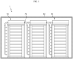
- FIG. 1 is a diagram for illustrating an energy storage system according to an embodiment of the present disclosure
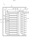
- FIG. 2 is a diagram for illustrating a battery rack of the energy storage system of FIG. 1
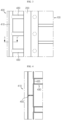
- FIG. 3 is a diagram for illustrating a pipe unit of the battery rack of the energy storage system of FIG. 2
- FIG. 4 is a partially sectioned view showing the pipe unit of FIG. 3
- FIG. 5 is a sectioned view showing the pipe unit of FIG. 3 , taken along the line A-A'
- FIGS. 6 and 7 are diagrams for illustrating hydraulic pressure adjusting units according to various embodiments of the pipe unit of FIG. 3
- FIG. 8 is a diagram for illustrating a valve unit of the battery rack of FIG. 2
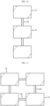
- FIG. 9 is a diagram for illustrating a flux supplement unit of the energy storage system of FIG. 1
- FIGS. 10 and 11 are diagrams for illustrating various connection patterns of the flux supplement unit of the energy storage system of FIG. 1 .
- an energy storage system 1 is an energy source and may be used for home or industrial use.
- the energy storage system 1 may include a plurality of battery racks 10, a rack container 50, and a flux supplement unit 70.
- the plurality of battery racks 10 may be disposed in a rack container 50, explained later.
- the plurality of battery racks 10 may include two or more battery racks.
- Each of the plurality of battery racks 10 may include a battery module 100, a rack case 200, a coolant tank 300, a pipe unit 400, a valve unit 500, a temperature sensor 600, and a control unit 700.
- the battery module 100 may be provided in plural.
- the plurality of battery modules 100 may be stacked on each other along an upper and lower direction of the battery rack 10.
- Each of the plurality of battery modules 100 may include at least one battery cell 110.
- each of the plurality of battery modules 100 will be described as including a plurality of battery cells 110.
- the plurality of battery cells 110 may be provided as secondary batteries, respectively.
- the plurality of battery cells 110 may include at least one of pouch-type secondary batteries, rectangular secondary batteries, and cylindrical secondary batteries.
- the plurality of battery cells 110 are pouch-type secondary batteries.
- the rack case 200 may accommodate the plurality of battery modules 100.
- the rack case 200 may accommodate the plurality of battery modules 100 to be stacked on each other in an upper and lower direction.
- the coolant tank 300 may be provided to an upper side of the rack case 200.
- the coolant tank 300 may contain a predetermined coolant therein. Accordingly, an accommodation space capable of accommodating the coolant may be provided in the coolant tank 300.
- the coolant may be provided as a liquid coolant.
- the coolant may be water.
- the coolant will be described as water.
- the pipe unit 400 may connect the coolant tank 300 and the plurality of battery modules 100.
- the pipe unit 400 may guide the coolant of the coolant tank 300, namely the water, to be supplied to the plurality of battery modules 100.
- the pipe unit 400 may include a main pipe 410, a module pipe 430, and a hydraulic pressure adjusting unit 450.
- the main pipe 410 is connected to a valve unit 500, explained later, and may be elongated to have a predetermined length along an upper and lower direction of the rack case 200.
- the main pipe 200 may be spaced apart from the rack case 200 by a predetermined interval.
- the module pipe 430 is connected to the main pipe 410 and may be disposed in a horizontal direction from the main pipe 410.
- the module pipe 430 is provided in plural, and the plurality of module pipes 430 may be connected to the battery modules 100, respectively.
- the plurality of module pipes 430 may be disposed to be spaced apart from each other by a predetermined distance along the upper and lower direction of the rack case 200.
- the plurality of module pipes 430 may connect the main pipe 410 and the plurality of battery modules 100 to each other.
- Each of the plurality of module pipes 430 may include a module valve 435.
- the module valve 435 may be provided to an internal flow path of each module pipe 430 to opened and closed.
- the module valve 435 may be electrically connected to a control unit 700, explained later.
- Each module valve 435 may be operated to open or close the internal flow path of the module pipe 430 according to the control of the control unit 700, explained later.
- the module valve 435 may also be configured to be opened or closed in a manner other than the control of the control unit 700.
- the module valve 435 may be provided as a member that is melted down or cut off at a preset temperature or above to open the internal flow path of the module pipe 430 when the battery module 100 is abnormally heated, in a state of being mounted in the module pipe 430 to close the internal flow path of the module pipe 430.
- the hydraulic pressure adjusting unit 450 is for adjusting a hydraulic pressure according to the height of the main pipe 410, and may be provided to an inner wall of the main pipe 410. Specifically, the hydraulic pressure adjusting unit 450 may be provided in plural, and the plurality of hydraulic pressure adjusting units 450 may be disposed between the plurality of module pipes 430, respectively, in the upper and lower direction of the main pipe 410.
- the plurality of hydraulic pressure adjusting units 450 may be formed to protrude by a predetermined length from the inner wall of the main pipe 410 toward a central portion of the main pipe 410.
- the inner diameter of the main pipe 410 having the plurality of hydraulic pressure adjusting units 450 may be relatively reduced smaller than the inner diameter of the main pipe 410 not having the plurality of hydraulic pressure adjusting units 450. Accordingly, a pipe loss may occur in the space of the main pipe 410 having the plurality of hydraulic pressure adjusting units 450 between the plurality of module pipes 430. When the water flows through the main pipe 410, this pipe loss offsets the pressure increased by gravity, so that the water may be supplied more evenly regardless of the height at any place of the plurality of module pipes 430.
- the hydraulic pressure is adjusted according to the height of the main pipe 410 by means of the plurality of hydraulic pressure adjusting units 450, when the water is supplied, the water may be fed evenly at any place of the plurality of battery modules 100, including an upper side, a lower side and a center side of the plurality of battery modules 100. Consequently, the plurality of hydraulic pressure adjusting units 450 may guide the water to be input with a uniform flux regardless of the height of the battery modules 100.
- the plurality of hydraulic pressure adjusting units 450 may also have other structures capable of causing a piping loss of the main pipe 410. That is, as shown in FIG. 6 , a plurality of hydraulic pressure adjusting units 460 may be provided as a plurality of ribs that protrude from the inner wall of the main pipe 410 toward the center of the main pipe 410 in a radial direction, and, as shown in FIG. 7 , a plurality of hydraulic pressure adjusting units 470 may be provided in a disk shape in which a plurality of holes are formed.
- the valve unit 500 is provided between the pipe unit 400 and the coolant tank 300, and when at least one battery module 100 among the plurality of battery modules 100 has a predetermined temperature or above, the valve unit 500 may be opened to feed the water in the coolant tank 300 to the pipe unit 400 so that the water is supplied to the plurality of battery modules 100.
- the valve unit 500 may include a valve body 510 and an opening/closing valve 530.
- the opening/closing valve 530 is provided to be opened and closed in the valve body 510, and may be disposed near the coolant tank 300.
- the opening/closing valve 530 may close the valve flow path 515 when the temperature of the plurality of battery modules 100 is lower than a predetermined temperature, and open the valve flow path 515 when the temperature of at least one battery module 100 among the plurality of battery modules 100 is higher than the predetermined temperature.
- the control unit 700 may be electrically connected to various the plurality of battery modules 100, the coolant tank 300, the plurality of temperature sensors 600, the module valve 435, the valve unit 500, a flow valve 75 of the flux supplement unit 70, explained later, and various electric components of the battery rack 10 to control the operations of the battery rack 10 and the flux supplement unit 70.
- the control unit 700 may control the operation of the opening/closing valve 530 of the valve unit 500, the operation of the module valve 435 of the module pipe 430 connected to the at least one battery module 100 at which the abnormal heat generation occurs, and the operation of the flow valve 75 of the flux supplement unit 70.
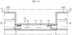
- the flux supplement unit 70 may connect the coolant tanks 300 of the plurality of battery racks 10 to each other.
- the flux supplement unit 70 may guide the water to be supplied to the coolant tank 300 connected to the opened valve unit 500, in order to prevent the flux of water flowing into the battery module 100 at the predetermined temperature or above from decreasing as the water in the coolant tank 300 of the at least one battery rack 10 where the valve unit 500 is opened is reduced.
- the flux supplement unit 70 may connect the coolant tank 300 of at least one battery rack 10 among the plurality of battery racks 10 and the coolant tank 300 of at least one other battery rack 10 adjacent to the coolant tank 300 of the at least one battery rack 10 to each other.
- the flux supplement unit 70 may be connected to a lower end of the coolant tanks 300 of the battery rack 10. Accordingly, when the flux supplement unit 70 is opened, the flow of water from one coolant tank 300 to another coolant tank 300 may be naturally performed by potential energy due to gravity.
- At least one flux supplement unit 70 or a plurality of flux supplement units 70 may be provided.
- the flux supplement unit 70 will be described as being provided in plural.
- the plurality of flux supplement units 70 may be provided to connect the coolant tanks 300 of the plurality of battery racks 10, and may be disposed along at least one direction.
- the plurality of flux supplement units 70 may be arranged in a one-dimensional shape along one direction of the plurality of battery racks 10, namely the upper and lower direction.
- the plurality of flux supplement units 80 may also be arranged in a two-dimensional shape in an upper and lower direction and a left and right direction according to the arrangement shape of the plurality of battery racks 10. This is merely an example, and the plurality of flux supplement units 70 may be arranged in more diverse and flexible patterns according to the arrangement shape of the plurality of battery racks 10.
- Each of the plurality of flux supplement units 70 may include a connection pipe 71 and a flow valve 75.
- connection pipe 71 is formed with a predetermined length and may have an internal flow path 73 for the flow of the water.
- the connection pipe 71 may be connected to the coolant tanks 300 of adjacent battery racks 10 to communicate therewith.
- At least one flow valve 75 may be provided, and the at least one flow valve 75 may be provided to the connection pipe 71 to open and close the internal flow path 73.
- the flow valve 75 may be electrically connected to the control unit 700, and may be opened and closed according to the control of the control unit 700.
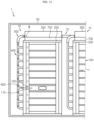
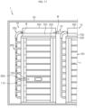
- FIGS. 12 to 17 are diagrams for illustrating an operation of the energy storage system when at least one battery module of the battery rack of the energy storage system of FIG. 1 is abnormally heated.
- temperature may increase rapidly due to abnormal heat generation in at least one battery module 100 among the plurality of battery modules 100 of the plurality of battery racks 10.
- a fire occurs in the battery module 100 that is abnormally heated, if the fire is transferred to adjacent battery modules 100, a greater risk such as explosion of the entire battery racks 10 may occur, so it is needed to rapidly block the transfer of the fire. That is, when at least one of the battery modules 100 ignites, it is necessary to more quickly block the propagation of flame and heat toward adjacent battery modules 100.
- the temperature sensor 600 near the battery module 100 whose temperature rises due to abnormal heat generation or the like may sense the temperature rise. After that, if the temperature sensed by the temperature sensor 600 is higher than a preset predetermined temperature, the control unit 700 may open the opening/closing valve 530 of the valve unit 500 and the module valve 435 of the module pipe 430 connected to the battery module 100 that is heated over the preset predetermined temperature.
- the water W supplied to the main pipe 410 of the pipe unit 400 may flow toward the module pipe 430 at which the module valve 435 is opened, among the plurality of module pipes 430, and be supplied to the battery module 100 that is heated abnormally.
- the water is supplied to the battery module 100 that is abnormally heated, so that the battery module 100 having the abnormal heat may be cooled more quickly. That is, in this embodiment, by using the water in the coolant tank 300, when a situation such as abnormal heat occurs, emergency cooling may be implemented by supplying the water to the battery module 100 that is abnormally heated. Thus, when at least one of the battery modules 100 ignites, the propagation of flame and heat to adjacent battery modules 100 may be prevented more quickly.
- the plurality of hydraulic pressure adjusting units 450 provided to the main pipe 410 may adjust the hydraulic pressure according to the height of the main pipe 410 so that the is supplied with the same flux at any place of the plurality of battery modules 100. That is, in this embodiment, it is possible to guide the water W to be input evenly regardless of the height of the stacked battery modules 100 by means of the plurality of hydraulic pressure adjusting units 450.
- the water when supplying water for cooling the abnormally heated battery module 100, the water may be guided to be input with a uniform flux by means of the hydraulic pressure adjusting units 450 regardless of the stack height, even though the stack height is different, for example in a case where a battery module 100 at an upper side is abnormally heated among the stacked battery modules 100, in a case where a battery module 100 at a lower side is abnormally heated, in a case where a battery module 100 at the center is abnormally heated, or the like.
- the water supplied when the battery module 100 stacked at an upper side is abnormally heated, the water supplied when the battery module 100 stacked at a lower side is abnormally heated, and the water supplied when the battery module 100 stacked at the center may be supplied with a uniform flux.
- the amount of the water W inside the coolant tank 300 that supplies the water W may be reduced.
- the control unit 700 may detect the amount of water W in the coolant tank 300 that supplies the water W. If the amount of water W in the coolant tank 300 that supplies the water W to the abnormally heated battery module 100 is less than a preset predetermined amount, water W may be supplied from the coolant tank 300 of an adjacent battery rack 10 to the coolant tank 300 in which the amount of water is less than the preset predetermined amount.
- control unit 700 may open the flow valve 75 of the flux supplement unit 70 to communicate the coolant tank 300 in which the amount of water is less than the preset predetermined amount with an adjacent coolant tank 300. Accordingly, the water W of the adjacent coolant tank 300 may flow along the internal flow path 73 of the connection pipe 71 of the flux supplement unit 70 and be supplied to the coolant tank 300 in which the amount of water is less than the preset predetermined amount.
- the coolant tank 300 which discharges the water W for emergency cooling, may be supplemented with the water W from the adjacent coolant tank 300 through the flux supplement unit 70, so that the water W may be continuously supplied to the abnormally heated battery module 100 for a certain period of time with the same flux.
- water when emergency cooling is performed to the battery module 100 that is abnormally heated, water may be input with the same flux for a certain period of time by means of the flux supplement unit 70, so the cooling performance may be maintained for a certain time during the emergency cooling.
- an energy storage system 1 which may more quickly prevent propagation of flame and heat to adjacent battery modules 100 when ignition occurs in at least one of battery modules 100.
Landscapes
- Chemical & Material Sciences (AREA)
- Chemical Kinetics & Catalysis (AREA)
- Electrochemistry (AREA)
- General Chemical & Material Sciences (AREA)
- Engineering & Computer Science (AREA)
- Manufacturing & Machinery (AREA)
- Automation & Control Theory (AREA)
- Secondary Cells (AREA)
- Battery Mounting, Suspending (AREA)
Claims (11)
- Energiespeichersystem (1), umfassend:einen Gestellbehälter (50) mit einem vorbestimmten Aufnahmeraum; gekennzeichnet durcheine Vielzahl von Batteriegestellen (10), die in dem Gestellbehälter (50) angeordnet sind und jeweils einen Kühlmitteltank (300) aufweisen, in dem ein vorbestimmtes Kühlmittel enthalten ist; undzumindest eine Flussergänzungseinheit (70, 80), die zum Verbinden der Kühlmitteltanks (300) der Vielzahl von Batteriegestellen (10) ausgelegt ist.
- Energiespeichersystem (1) nach Anspruch 1,
wobei jedes der Vielzahl von Batteriegestellen (10) umfasst:eine Vielzahl von Batteriemodulen (100), die entlang einer auf-und-ab-Richtung des Batteriegestells (10) aufeinander gestapelt sind und jeweils zumindest eine Batteriezelle (110) aufweisen;ein Gestellgehäuse (200), das zum Aufnehmen der Vielzahl von Batteriemodulen (100) ausgelegt ist;den Kühlmitteltank (300), der an einer Oberseite des Gestellgehäuses (200) vorgesehen ist;eine Rohreinheit (400), die zum Verbinden des Kühlmitteltanks (300) und der Vielzahl von Batteriemodulen (100) ausgelegt ist; undeine Ventileinheit (500), die zwischen der Rohreinheit (400) und dem Kühlmitteltank (300) vorgesehen ist und die dazu ausgelegt ist, zu öffnen, wenn zumindest ein Batteriemodul (100) eine Temperatur über einer vorbestimmten Temperatur unter der Vielzahl von Batteriemodulen (100) aufweist, um das Kühlmittel des Kühlmitteltanks (300) an die Rohreinheit (400) abzugeben, so dass das Kühlmittel dem Batteriemodul (100) über der vorbestimmten Temperatur zugeführt wird. - Energiespeichersystem (1) nach Anspruch 2,
wobei, wenn die Ventileinheit (500) geöffnet ist, die zumindest eine Flussergänzungseinheit (70, 80) das Kühlmittel dem Kühlmitteltank (300) zuführt, der mit der geöffneten Ventileinheit (500) verbunden ist, um zu verhindern, dass der Fluss des Kühlmittels, das dem Batteriemodul (100) über der vorbestimmten Temperatur zugeführt wird, abnimmt, wenn die Menge des Kühlmittels in dem Kühlmitteltank (300) verringert wird. - Energiespeichersystem (1) nach Anspruch 3,
wobei die zumindest eine Flussergänzungseinheit (70, 80) einen internen Strömungspfad (73) für die Strömung des Kühlmittels aufweist und den Kühlmitteltank (300) des Batteriegestells mit dem Kühlmitteltank (300) zumindest eines dazu benachbarten Batteriegestells verbindet. - Energiespeichersystem (1) nach Anspruch 4,
wobei die zumindest eine Flussergänzungseinheit (70, 80) umfasst:ein Verbindungsrohr (71), das den internen Strömungsweg (73) aufweist und in einer vorbestimmten Länge ausgebildet ist; undzumindest ein Strömungsventil, das an dem Verbindungsrohr (71) vorgesehen ist, um den internen Strömungspfad (73) zu öffnen oder zu schließen. - Energiespeichersystem (1) nach Anspruch 3,
wobei jedes der Vielzahl von Batteriegestellen (10) zumindest einen Temperatursensor (600) umfasst, der an dem Gestellgehäuse (200) vorgesehen ist, um die Temperatur der Vielzahl von Batteriemodulen (100) zu messen. - Energiespeichersystem (1) nach Anspruch 6,
wobei jedes der Vielzahl von Batteriegestellen (10) eine Steuereinheit (700) umfasst, die elektrisch mit dem zumindest einen Temperatursensor (600), der Ventileinheit (500) und der zumindest einen Flussergänzungseinheit (70, 80) verbunden ist, um den Betrieb der Ventileinheit (500) und der Flussergänzungseinheit (70, 80) zu steuern. - Energiespeichersystem (1) nach Anspruch 3,
wobei die Flussergänzungseinheit (70, 80) zum Verbinden der Kühlmitteltanks (300) der Vielzahl von Batteriegestellen (10) mehrfach vorgesehen ist. - Energiespeichersystem (1) nach Anspruch 8,
wobei die Mehrzahl von Flussergänzungseinheiten (70, 80) entlang zumindest einer Richtung der Vielzahl von Batteriegestellen (10) angeordnet ist. - Energiespeichersystem (1) nach Anspruch 2,
wobei die Rohreinheit (400) umfasst:ein Hauptrohr (410), das mit der Ventileinheit (500) verbunden ist; undeine Vielzahl von Modulrohren, die mit dem Hauptrohr (410) verbunden sind und jeweils mit den Batteriemodulen (100) verbunden sind. - Energiespeichersystem (1) nach Anspruch 1,
wobei das Kühlmittel Wasser ist.
Applications Claiming Priority (2)
| Application Number | Priority Date | Filing Date | Title |
|---|---|---|---|
| KR1020190088484A KR102767147B1 (ko) | 2019-07-22 | 2019-07-22 | 전력 저장 장치 |
| PCT/KR2020/009119 WO2021015469A1 (ko) | 2019-07-22 | 2020-07-10 | 전력 저장 장치 |
Publications (3)
| Publication Number | Publication Date |
|---|---|
| EP3975321A1 EP3975321A1 (de) | 2022-03-30 |
| EP3975321A4 EP3975321A4 (de) | 2022-08-03 |
| EP3975321B1 true EP3975321B1 (de) | 2025-04-02 |
Family
ID=74193992
Family Applications (1)
| Application Number | Title | Priority Date | Filing Date |
|---|---|---|---|
| EP20843688.1A Active EP3975321B1 (de) | 2019-07-22 | 2020-07-10 | Stromspeichervorrichtung |
Country Status (10)
| Country | Link |
|---|---|
| US (2) | US12288859B2 (de) |
| EP (1) | EP3975321B1 (de) |
| JP (1) | JP7199581B2 (de) |
| KR (1) | KR102767147B1 (de) |
| CN (1) | CN114175356B (de) |
| AU (1) | AU2020317839B2 (de) |
| ES (1) | ES3030958T3 (de) |
| HU (1) | HUE071188T2 (de) |
| PL (1) | PL3975321T3 (de) |
| WO (1) | WO2021015469A1 (de) |
Families Citing this family (6)
| Publication number | Priority date | Publication date | Assignee | Title |
|---|---|---|---|---|
| KR102375766B1 (ko) * | 2021-03-09 | 2022-03-18 | 울산과학기술원 | 배터리팩을 수용하는 배터리랙 및 배터리랙 모듈 |
| US12191518B2 (en) | 2022-04-05 | 2025-01-07 | GM Global Technology Operations LLC | Active thermal management systems with multi-purpose reservoirs for liquid immersion cooled battery assemblies |
| US12148910B2 (en) * | 2022-07-19 | 2024-11-19 | GM Global Technology Operations LLC | Thermal management systems with passive quenching sacks for liquid immersion cooled battery assemblies |
| CN116031558B (zh) * | 2023-02-07 | 2024-05-17 | 中国铁塔股份有限公司浙江省分公司 | 直发直供光储一体的节能降耗系统 |
| US20240332670A1 (en) * | 2023-03-28 | 2024-10-03 | EV Battery Technology Inc. | Electric Vehicle Battery Pack Cooling System |
| JP7746492B2 (ja) * | 2023-08-23 | 2025-09-30 | 台達電子工業股▲ふん▼有限公司 | エネルギー貯蔵キャビネット及びその電池モジュール |
Family Cites Families (36)
| Publication number | Priority date | Publication date | Assignee | Title |
|---|---|---|---|---|
| JPS512640U (de) * | 1974-06-21 | 1976-01-09 | ||
| JPH08338051A (ja) * | 1995-06-14 | 1996-12-24 | Sumitomo Electric Ind Ltd | 緊急用貯水システム |
| JP2007032250A (ja) * | 2005-07-25 | 2007-02-08 | Masamitsu Onishi | ・ポリジャコ:テオリーくん370号・ホース付穴開き容器締付具:テオリーくん371号・ポリタンラック:テオリーくん372号 |
| WO2010025761A1 (en) * | 2008-09-02 | 2010-03-11 | Abb Research Ltd | System and method for fire protection |
| DE102009038065A1 (de) | 2009-08-19 | 2011-02-24 | Li-Tec Battery Gmbh | Verfahren und Vorrichtung zum Kühlen eines elektrochemischen Energiespeichers |
| KR101143279B1 (ko) * | 2009-08-20 | 2012-05-11 | 주식회사 엘지화학 | 신규한 냉각구조를 가진 전지팩 |
| EP2544286B1 (de) * | 2010-03-04 | 2016-06-01 | Panasonic Corporation | Brennstoffzellensystem und betriebsverfahren dafür |
| CN102576840B (zh) * | 2010-07-30 | 2014-09-03 | 三洋电机株式会社 | 二次电池收纳系统机架 |
| KR101256296B1 (ko) | 2010-12-30 | 2013-04-18 | 주식회사 포스코아이씨티 | 배터리 시스템 |
| CN102544625B (zh) | 2012-03-05 | 2014-04-02 | 苏州奥杰汽车工业有限公司 | 一种半导体水冷电池冷却装置 |
| KR20130104165A (ko) | 2012-03-13 | 2013-09-25 | 에스케이이노베이션 주식회사 | 열전소자를 이용한 배터리 냉각시스템 |
| JP6213712B2 (ja) | 2013-04-30 | 2017-10-18 | 日産自動車株式会社 | 注液システム |
| JP2015098326A (ja) * | 2013-10-17 | 2015-05-28 | データシステム株式会社 | ポリタンク及び給水装置 |
| JP2015220177A (ja) | 2014-05-20 | 2015-12-07 | 株式会社Gsユアサ | 蓄電装置 |
| WO2015186343A1 (ja) * | 2014-06-06 | 2015-12-10 | パナソニックIpマネジメント株式会社 | 電池室 |
| CN106450562B (zh) * | 2015-08-07 | 2021-07-02 | 宝马股份公司 | 能量存储装置、电池装置、机动车和冷却剂流控制方法 |
| JP2019075191A (ja) * | 2016-03-08 | 2019-05-16 | パナソニックIpマネジメント株式会社 | 蓄電装置 |
| KR102104383B1 (ko) | 2016-04-25 | 2020-04-24 | 주식회사 엘지화학 | 전력 저장 장치 및 전력 저장 장치 냉각 방법 |
| DE102016120834A1 (de) | 2016-11-02 | 2018-05-03 | E-Seven Systems Technology Management Ltd | Platine zur Verbindung von Batteriezellen |
| US10608299B2 (en) * | 2016-08-09 | 2020-03-31 | Nio Usa, Inc. | Cooling system for a battery pack system for quickly addressing thermal runaway |
| JP6779079B2 (ja) * | 2016-09-26 | 2020-11-04 | 日本ドライケミカル株式会社 | 二次電池の熱暴走抑止システム |
| KR101706717B1 (ko) | 2016-11-04 | 2017-03-09 | 주식회사 아하정보통신 | 에너지 저장시스템의 배터리팩 화재예방장치 |
| CN106972207B (zh) | 2016-11-11 | 2020-02-28 | 蔚来汽车有限公司 | 模块化可扩展的温度调节系统 |
| KR101761676B1 (ko) * | 2016-12-29 | 2017-07-27 | 엠에이치기술개발 주식회사 | 배터리용 냉각장치 |
| KR102708086B1 (ko) | 2017-02-09 | 2024-09-19 | 주식회사 엘지에너지솔루션 | 배터리를 수용하는 구조물을 위한 화재 보호 시스템 |
| CN107069140B (zh) | 2017-03-30 | 2019-05-14 | 天津市捷威动力工业有限公司 | 新能源汽车锂离子电池包热失控控制系统及电池包 |
| CN110462921B (zh) | 2017-04-05 | 2022-12-09 | 西门子能源有限责任公司 | 冷却系统和方法 |
| CN109103539A (zh) * | 2017-06-20 | 2018-12-28 | 苏州科易新动力科技有限公司 | 一种抑制电芯热失控的装置及方法 |
| CN107398049B (zh) * | 2017-06-22 | 2020-11-20 | 哲弗智能系统(上海)有限公司 | 一种使用混合灭火剂的车载电池灭火结构 |
| KR102258816B1 (ko) | 2017-06-27 | 2021-05-31 | 주식회사 엘지에너지솔루션 | 배터리 모듈 |
| CN207098011U (zh) * | 2017-07-07 | 2018-03-13 | 埃思柯(上海)空调冷冻设备有限公司 | 一种用于储能电池机柜上的冷却装置 |
| CN107394308B (zh) | 2017-07-17 | 2020-02-07 | 广州汽车集团股份有限公司 | 车辆电池充电冷却的系统及方法 |
| US20190077275A1 (en) * | 2017-09-12 | 2019-03-14 | Sf Motors, Inc. | Dynamic cooling control for battery systems |
| CN108879005A (zh) * | 2018-07-09 | 2018-11-23 | 毛燕婷 | 一种新能源汽车电池箱用温度控制装置 |
| KR101939812B1 (ko) | 2018-08-29 | 2019-01-18 | (주)대은 | 안전성이 강화된 공조 기능을 포함하는 ess시스템 |
| CN208862127U (zh) * | 2018-08-31 | 2019-05-14 | 比亚迪股份有限公司 | 具有灭火功能的电池冷却系统及车辆 |
-
2019
- 2019-07-22 KR KR1020190088484A patent/KR102767147B1/ko active Active
-
2020
- 2020-07-10 AU AU2020317839A patent/AU2020317839B2/en active Active
- 2020-07-10 HU HUE20843688A patent/HUE071188T2/hu unknown
- 2020-07-10 JP JP2021574857A patent/JP7199581B2/ja active Active
- 2020-07-10 WO PCT/KR2020/009119 patent/WO2021015469A1/ko not_active Ceased
- 2020-07-10 EP EP20843688.1A patent/EP3975321B1/de active Active
- 2020-07-10 PL PL20843688.1T patent/PL3975321T3/pl unknown
- 2020-07-10 US US17/619,177 patent/US12288859B2/en active Active
- 2020-07-10 CN CN202080051347.2A patent/CN114175356B/zh active Active
- 2020-07-10 ES ES20843688T patent/ES3030958T3/es active Active
-
2025
- 2025-01-02 US US19/007,967 patent/US20250132418A1/en active Pending
Also Published As
| Publication number | Publication date |
|---|---|
| CN114175356B (zh) | 2025-04-29 |
| EP3975321A4 (de) | 2022-08-03 |
| CN114175356A (zh) | 2022-03-11 |
| EP3975321A1 (de) | 2022-03-30 |
| JP7199581B2 (ja) | 2023-01-05 |
| JP2022536405A (ja) | 2022-08-15 |
| WO2021015469A1 (ko) | 2021-01-28 |
| US20250132418A1 (en) | 2025-04-24 |
| KR102767147B1 (ko) | 2025-02-11 |
| HUE071188T2 (hu) | 2025-08-28 |
| AU2020317839B2 (en) | 2025-08-21 |
| ES3030958T3 (en) | 2025-07-02 |
| AU2020317839A1 (en) | 2022-02-17 |
| US20220359931A1 (en) | 2022-11-10 |
| PL3975321T3 (pl) | 2025-06-30 |
| US12288859B2 (en) | 2025-04-29 |
| KR20210011262A (ko) | 2021-02-01 |
Similar Documents
| Publication | Publication Date | Title |
|---|---|---|
| EP3975321B1 (de) | Stromspeichervorrichtung | |
| EP3333932B1 (de) | Batteriesystem | |
| EP3958375A1 (de) | Batterierack und stromspeichervorrichtung damit | |
| US12255303B2 (en) | Battery rack and power storage device comprising same | |
| EP3905375A1 (de) | Batterierack und damit versehene energiespeichervorrichtung | |
| AU2020375429A1 (en) | Battery module, and battery rack and power storage device comprising battery module | |
| EP3993142B1 (de) | Batterierack und stromspeichervorrichtung damit | |
| EP4318773A1 (de) | Batteriepack, energiespeichersystem und fahrzeug mit batteriepack | |
| JP7538888B2 (ja) | バッテリパック及びこのようなバッテリパックを含む自動車 | |
| EP4023308B1 (de) | Batteriemodul, batteriegestell mit dem batteriemodul und energiespeichervorrichtung mit dem batteriegestell | |
| EP4354597A1 (de) | Batteriepack und energiespeichersystem sowie fahrzeug mit dem batteriepack | |
| KR102851104B1 (ko) | 배터리 랙 및 이를 포함하는 전력 저장 장치 | |
| KR20130081027A (ko) | 배터리모듈 | |
| EP4152481A1 (de) | Batteriegestell und energiespeichervorrichtung mit dem batteriegestell | |
| KR102667183B1 (ko) | 배터리 모듈, 이러한 배터리 모듈을 포함하는 배터리 팩, 이러한 배터리 팩을 포함하는 에너지 저장 장치 및 자동차 |
Legal Events
| Date | Code | Title | Description |
|---|---|---|---|
| STAA | Information on the status of an ep patent application or granted ep patent |
Free format text: STATUS: THE INTERNATIONAL PUBLICATION HAS BEEN MADE |
|
| PUAI | Public reference made under article 153(3) epc to a published international application that has entered the european phase |
Free format text: ORIGINAL CODE: 0009012 |
|
| STAA | Information on the status of an ep patent application or granted ep patent |
Free format text: STATUS: REQUEST FOR EXAMINATION WAS MADE |
|
| 17P | Request for examination filed |
Effective date: 20211221 |
|
| AK | Designated contracting states |
Kind code of ref document: A1 Designated state(s): AL AT BE BG CH CY CZ DE DK EE ES FI FR GB GR HR HU IE IS IT LI LT LU LV MC MK MT NL NO PL PT RO RS SE SI SK SM TR |
|
| A4 | Supplementary search report drawn up and despatched |
Effective date: 20220630 |
|
| RIC1 | Information provided on ipc code assigned before grant |
Ipc: H01M 10/48 20060101ALI20220624BHEP Ipc: H01M 10/613 20140101ALI20220624BHEP Ipc: H01M 10/627 20140101ALI20220624BHEP Ipc: H01M 10/63 20140101ALI20220624BHEP Ipc: H01M 10/6567 20140101AFI20220624BHEP |
|
| DAV | Request for validation of the european patent (deleted) | ||
| DAX | Request for extension of the european patent (deleted) | ||
| GRAP | Despatch of communication of intention to grant a patent |
Free format text: ORIGINAL CODE: EPIDOSNIGR1 |
|
| STAA | Information on the status of an ep patent application or granted ep patent |
Free format text: STATUS: GRANT OF PATENT IS INTENDED |
|
| INTG | Intention to grant announced |
Effective date: 20241113 |
|
| GRAS | Grant fee paid |
Free format text: ORIGINAL CODE: EPIDOSNIGR3 |
|
| GRAA | (expected) grant |
Free format text: ORIGINAL CODE: 0009210 |
|
| STAA | Information on the status of an ep patent application or granted ep patent |
Free format text: STATUS: THE PATENT HAS BEEN GRANTED |
|
| AK | Designated contracting states |
Kind code of ref document: B1 Designated state(s): AL AT BE BG CH CY CZ DE DK EE ES FI FR GB GR HR HU IE IS IT LI LT LU LV MC MK MT NL NO PL PT RO RS SE SI SK SM TR |
|
| REG | Reference to a national code |
Ref country code: GB Ref legal event code: FG4D |
|
| P01 | Opt-out of the competence of the unified patent court (upc) registered |
Free format text: CASE NUMBER: APP_10572/2025 Effective date: 20250304 |
|
| REG | Reference to a national code |
Ref country code: CH Ref legal event code: EP |
|
| REG | Reference to a national code |
Ref country code: IE Ref legal event code: FG4D |
|
| REG | Reference to a national code |
Ref country code: DE Ref legal event code: R096 Ref document number: 602020048859 Country of ref document: DE |
|
| REG | Reference to a national code |
Ref country code: SE Ref legal event code: TRGR |
|
| REG | Reference to a national code |
Ref country code: ES Ref legal event code: FG2A Ref document number: 3030958 Country of ref document: ES Kind code of ref document: T3 Effective date: 20250702 |
|
| PGFP | Annual fee paid to national office [announced via postgrant information from national office to epo] |
Ref country code: PL Payment date: 20250625 Year of fee payment: 6 |
|
| PGFP | Annual fee paid to national office [announced via postgrant information from national office to epo] |
Ref country code: GB Payment date: 20250624 Year of fee payment: 6 |
|
| PGFP | Annual fee paid to national office [announced via postgrant information from national office to epo] |
Ref country code: BE Payment date: 20250425 Year of fee payment: 6 |
|
| PGFP | Annual fee paid to national office [announced via postgrant information from national office to epo] |
Ref country code: FR Payment date: 20250624 Year of fee payment: 6 |
|
| PGFP | Annual fee paid to national office [announced via postgrant information from national office to epo] |
Ref country code: SE Payment date: 20250624 Year of fee payment: 6 |
|
| REG | Reference to a national code |
Ref country code: NL Ref legal event code: MP Effective date: 20250402 |
|
| PGFP | Annual fee paid to national office [announced via postgrant information from national office to epo] |
Ref country code: HU Payment date: 20250721 Year of fee payment: 6 |
|
| REG | Reference to a national code |
Ref country code: HU Ref legal event code: AG4A Ref document number: E071188 Country of ref document: HU |
|
| PG25 | Lapsed in a contracting state [announced via postgrant information from national office to epo] |
Ref country code: NL Free format text: LAPSE BECAUSE OF FAILURE TO SUBMIT A TRANSLATION OF THE DESCRIPTION OR TO PAY THE FEE WITHIN THE PRESCRIBED TIME-LIMIT Effective date: 20250402 |
|
| REG | Reference to a national code |
Ref country code: AT Ref legal event code: MK05 Ref document number: 1782233 Country of ref document: AT Kind code of ref document: T Effective date: 20250402 |
|
| PG25 | Lapsed in a contracting state [announced via postgrant information from national office to epo] |
Ref country code: PT Free format text: LAPSE BECAUSE OF FAILURE TO SUBMIT A TRANSLATION OF THE DESCRIPTION OR TO PAY THE FEE WITHIN THE PRESCRIBED TIME-LIMIT Effective date: 20250804 Ref country code: FI Free format text: LAPSE BECAUSE OF FAILURE TO SUBMIT A TRANSLATION OF THE DESCRIPTION OR TO PAY THE FEE WITHIN THE PRESCRIBED TIME-LIMIT Effective date: 20250402 |
|
| PGFP | Annual fee paid to national office [announced via postgrant information from national office to epo] |
Ref country code: ES Payment date: 20250822 Year of fee payment: 6 |
|
| PGFP | Annual fee paid to national office [announced via postgrant information from national office to epo] |
Ref country code: DE Payment date: 20250624 Year of fee payment: 6 |
|
| REG | Reference to a national code |
Ref country code: LT Ref legal event code: MG9D |
|
| PG25 | Lapsed in a contracting state [announced via postgrant information from national office to epo] |
Ref country code: GR Free format text: LAPSE BECAUSE OF FAILURE TO SUBMIT A TRANSLATION OF THE DESCRIPTION OR TO PAY THE FEE WITHIN THE PRESCRIBED TIME-LIMIT Effective date: 20250703 Ref country code: NO Free format text: LAPSE BECAUSE OF FAILURE TO SUBMIT A TRANSLATION OF THE DESCRIPTION OR TO PAY THE FEE WITHIN THE PRESCRIBED TIME-LIMIT Effective date: 20250702 |
|
| PG25 | Lapsed in a contracting state [announced via postgrant information from national office to epo] |
Ref country code: BG Free format text: LAPSE BECAUSE OF FAILURE TO SUBMIT A TRANSLATION OF THE DESCRIPTION OR TO PAY THE FEE WITHIN THE PRESCRIBED TIME-LIMIT Effective date: 20250402 |
|
| PG25 | Lapsed in a contracting state [announced via postgrant information from national office to epo] |
Ref country code: HR Free format text: LAPSE BECAUSE OF FAILURE TO SUBMIT A TRANSLATION OF THE DESCRIPTION OR TO PAY THE FEE WITHIN THE PRESCRIBED TIME-LIMIT Effective date: 20250402 |
|
| PG25 | Lapsed in a contracting state [announced via postgrant information from national office to epo] |
Ref country code: AT Free format text: LAPSE BECAUSE OF FAILURE TO SUBMIT A TRANSLATION OF THE DESCRIPTION OR TO PAY THE FEE WITHIN THE PRESCRIBED TIME-LIMIT Effective date: 20250402 |
|
| PG25 | Lapsed in a contracting state [announced via postgrant information from national office to epo] |
Ref country code: RS Free format text: LAPSE BECAUSE OF FAILURE TO SUBMIT A TRANSLATION OF THE DESCRIPTION OR TO PAY THE FEE WITHIN THE PRESCRIBED TIME-LIMIT Effective date: 20250702 |
|
| PG25 | Lapsed in a contracting state [announced via postgrant information from national office to epo] |
Ref country code: IS Free format text: LAPSE BECAUSE OF FAILURE TO SUBMIT A TRANSLATION OF THE DESCRIPTION OR TO PAY THE FEE WITHIN THE PRESCRIBED TIME-LIMIT Effective date: 20250802 |
|
| PG25 | Lapsed in a contracting state [announced via postgrant information from national office to epo] |
Ref country code: LV Free format text: LAPSE BECAUSE OF FAILURE TO SUBMIT A TRANSLATION OF THE DESCRIPTION OR TO PAY THE FEE WITHIN THE PRESCRIBED TIME-LIMIT Effective date: 20250402 |