EP3974886B1 - Bildgebungslinse und bildaufnahmevorrichtung - Google Patents
Bildgebungslinse und bildaufnahmevorrichtung Download PDFInfo
- Publication number
- EP3974886B1 EP3974886B1 EP20831984.8A EP20831984A EP3974886B1 EP 3974886 B1 EP3974886 B1 EP 3974886B1 EP 20831984 A EP20831984 A EP 20831984A EP 3974886 B1 EP3974886 B1 EP 3974886B1
- Authority
- EP
- European Patent Office
- Prior art keywords
- lens
- imaging
- object side
- lens surface
- represented
- Prior art date
- Legal status (The legal status is an assumption and is not a legal conclusion. Google has not performed a legal analysis and makes no representation as to the accuracy of the status listed.)
- Active
Links
Images


Classifications
-
- G—PHYSICS
- G02—OPTICS
- G02B—OPTICAL ELEMENTS, SYSTEMS OR APPARATUS
- G02B13/00—Optical objectives specially designed for the purposes specified below
- G02B13/04—Reversed telephoto objectives
-
- G—PHYSICS
- G02—OPTICS
- G02B—OPTICAL ELEMENTS, SYSTEMS OR APPARATUS
- G02B13/00—Optical objectives specially designed for the purposes specified below
- G02B13/001—Miniaturised objectives for electronic devices, e.g. portable telephones, webcams, PDAs, small digital cameras
- G02B13/0015—Miniaturised objectives for electronic devices, e.g. portable telephones, webcams, PDAs, small digital cameras characterised by the lens design
- G02B13/002—Miniaturised objectives for electronic devices, e.g. portable telephones, webcams, PDAs, small digital cameras characterised by the lens design having at least one aspherical surface
- G02B13/0045—Miniaturised objectives for electronic devices, e.g. portable telephones, webcams, PDAs, small digital cameras characterised by the lens design having at least one aspherical surface having five or more lenses
-
- G—PHYSICS
- G02—OPTICS
- G02B—OPTICAL ELEMENTS, SYSTEMS OR APPARATUS
- G02B13/00—Optical objectives specially designed for the purposes specified below
- G02B13/001—Miniaturised objectives for electronic devices, e.g. portable telephones, webcams, PDAs, small digital cameras
- G02B13/008—Miniaturised objectives for electronic devices, e.g. portable telephones, webcams, PDAs, small digital cameras designed for infrared light
-
- G—PHYSICS
- G02—OPTICS
- G02B—OPTICAL ELEMENTS, SYSTEMS OR APPARATUS
- G02B13/00—Optical objectives specially designed for the purposes specified below
- G02B13/06—Panoramic objectives; So-called "sky lenses" including panoramic objectives having reflecting surfaces
-
- G—PHYSICS
- G02—OPTICS
- G02B—OPTICAL ELEMENTS, SYSTEMS OR APPARATUS
- G02B13/00—Optical objectives specially designed for the purposes specified below
- G02B13/18—Optical objectives specially designed for the purposes specified below with lenses having one or more non-spherical faces, e.g. for reducing geometrical aberration
-
- G—PHYSICS
- G02—OPTICS
- G02B—OPTICAL ELEMENTS, SYSTEMS OR APPARATUS
- G02B27/00—Optical systems or apparatus not provided for by any of the groups G02B1/00 - G02B26/00, G02B30/00
- G02B27/0018—Optical systems or apparatus not provided for by any of the groups G02B1/00 - G02B26/00, G02B30/00 with means for preventing ghost images
-
- G—PHYSICS
- G02—OPTICS
- G02B—OPTICAL ELEMENTS, SYSTEMS OR APPARATUS
- G02B9/00—Optical objectives characterised both by the number of the components and their arrangements according to their sign, i.e. + or -
- G02B9/04—Optical objectives characterised both by the number of the components and their arrangements according to their sign, i.e. + or - having two components only
- G02B9/10—Optical objectives characterised both by the number of the components and their arrangements according to their sign, i.e. + or - having two components only one + and one - component
-
- G—PHYSICS
- G02—OPTICS
- G02B—OPTICAL ELEMENTS, SYSTEMS OR APPARATUS
- G02B9/00—Optical objectives characterised both by the number of the components and their arrangements according to their sign, i.e. + or -
- G02B9/60—Optical objectives characterised both by the number of the components and their arrangements according to their sign, i.e. + or - having five components only
-
- G—PHYSICS
- G02—OPTICS
- G02B—OPTICAL ELEMENTS, SYSTEMS OR APPARATUS
- G02B9/00—Optical objectives characterised both by the number of the components and their arrangements according to their sign, i.e. + or -
- G02B9/62—Optical objectives characterised both by the number of the components and their arrangements according to their sign, i.e. + or - having six components only
-
- G—PHYSICS
- G02—OPTICS
- G02B—OPTICAL ELEMENTS, SYSTEMS OR APPARATUS
- G02B13/00—Optical objectives specially designed for the purposes specified below
- G02B13/001—Miniaturised objectives for electronic devices, e.g. portable telephones, webcams, PDAs, small digital cameras
- G02B13/0055—Miniaturised objectives for electronic devices, e.g. portable telephones, webcams, PDAs, small digital cameras employing a special optical element
- G02B13/006—Miniaturised objectives for electronic devices, e.g. portable telephones, webcams, PDAs, small digital cameras employing a special optical element at least one element being a compound optical element, e.g. cemented elements
-
- G—PHYSICS
- G02—OPTICS
- G02B—OPTICAL ELEMENTS, SYSTEMS OR APPARATUS
- G02B5/00—Optical elements other than lenses
- G02B5/20—Filters
- G02B5/208—Filters for use with infrared or ultraviolet radiation, e.g. for separating visible light from infrared and/or ultraviolet radiation
Definitions
- This disclosure relates to an imaging lens and an imaging apparatus.
- in-vehicle cameras In recent years, surveillance cameras, in-vehicle cameras and so on are in widespread use. With spread of an imaging lens for the surveillance cameras and in-vehicle cameras (referred to as the "in-vehicle cameras, etc.”), a simpler configuration and higher performance are required.
- the performance of the in-vehicle cameras, etc. includes a wide angle of view, good image quality, no degradation in performance with temperature changes, and small size.
- JP2010-145828A an imaging lens having 5 elements in 4 groups with a concave lens surface on the object side is disclosed.
- JP 2019 066645 A discloses a wide-angle lens comprising a first lens, a second lens, a third lens, a fourth lens, an aperture stop, a fifth lens, a cemented sixth lens and a seventh lens, wherein the first lens and the fifth lens are glass lenses, while the second lens, the third lens, the fourth lens, and the cemented lens are plastic lenses.
- the present invention provides an imaging lens according to claim 1 and an imaging apparatus according to claim 4. Preferred embodiments are described in the dependent claims.
- the in-vehicle cameras, etc. include a CCD (Charge Coupled Device), a CMOS (Complementary Metal-Oxide Semiconductor), or the like as an imaging element.
- the in-vehicle cameras, etc. are provided with a function of preventing unwanted light from entering the imaging element in order to prevent deterioration of image quality.
- the imaging lens and the imaging apparatus of the present disclosure that suppress the deterioration of image quality with a simple configuration will be described.
- An imaging lens includes a front group having negative power, an aperture stop, and a rear group having positive power, in order from the object side.
- a first lens surface closest to the object side has a convex shape toward the object side.
- a second lens surface closest to the object side has a convex shape toward the object side
- a third lens surface closest to an image side has a convex shape toward the image side
- the third lens surface has an infrared ray cut coat.
- the imaging lens satisfies the following condition (1): 1.6 ⁇ Rr + Re / Da ⁇ 2.3
- Rr represents a curvature radius of the second lens surface
- Re represents a curvature radius of the third lens surface
- Da represents a distance from the second lens surface to the third lens surface on an optical axis.
- the front group includes a concave meniscus-shaped first lens having the first lens surface and a concave meniscus-shaped second lens in order from the object side.
- the second lens is arranged with its convex surface facing the image side.
- the rear group includes a third lens having the second lens surface, a fourth lens, and a cemented lens in order from the object side.
- the third lens, the fourth lens, and the cemented lens all have positive power.
- the cemented lens is composed of a fifth lens, which is a concave lens, and a sixth lens, which is a convex lens, in order from the object side.
- the sixth lens may have the third lens surface.
- R1 represents a curvature radius of the first lens surface
- Re represents the curvature radius of the third lens surface
- Dt represents a distance from the first lens surface to the third lens surface on the optical axis.
- An imaging apparatus includes any of the above imaging lenses and a flat plate-shaped cover glass.
- R1 represents the curvature radius of the first lens surface
- Dt represents the distance from the first lens surface to the third lens surface on the optical axis
- Db represents the distance from the third lens surface to the object side of the cover glass on the optical axis.
- Rr represents the curvature radius of the second lens surface
- Da represents the distance from the second lens surface to the third lens surface on the optical axis
- Db represents the distance from the third lens surface to the object side of the cover glass on the optical axis.
- Re represents the curvature radius of the third lens surface
- Db represents the distance from the third lens surface to the object side of the cover glass on the optical axis.
- the imaging element has sensitivity also in the infrared region. Therefore, the quality of the image may deteriorate due to the infrared rays incident on the imaging element.
- an infrared ray filter or an infrared ray cut coat on the lens, etc. is provided to prevent infrared rays from entering the imaging element (infrared ray cutting function), thereby preventing the deterioration of image quality caused by infrared rays.
- the incident light from a particularly bright light source is partially reflected by the incident side of the infrared ray filter (the object side of the imaging lens).
- this reflected light is re-reflected by for example the lens surface facing the infrared ray filter and is imaged on the light receiving surface of the imaging element, it becomes a so-called ghost image, which may cause the deterioration of image quality .
- priority is generally given to the infrared ray cut performance, which may reduce the anti-reflection performance.
- one embodiment of the present disclosure has the following structure.
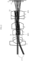
- an imaging apparatus 20 includes an imaging lens 10 and an image sensor 11.
- the image sensor 11 is equipped with a cover glass CG to protect an imaging plane IP. Therefore, the imaging lens 10 is a lens that images an object by forming an image of the object on the imaging plane IP through the cover glass CG.
- the imaging lens 10 has a front group G1 with negative power, an aperture stop ST, and a rear group G2 with positive power, which are arranged along an optical axis Z1 in order from the object side.
- the imaging lens 10 is a retrofocus type wide-angle lens.
- the angle of view exceeds, for example, 100 degrees.
- the temperature environment for this lens is, for example, from about -40°C to about 120°C.
- the front group G1 includes a first lens L1 and a second lens L2 in order from the object side.
- the rear group G2 includes a third lens L3, a fourth lens L4, a fifth lens L5, and a sixth lens L6 in order from the object side.
- the fifth lens L5 and the sixth lens L6 form a cemented lens CL. Therefore, the imaging lens 10 of this embodiment has 6 elements in 5 groups.
- the aperture stop ST is provided between the second lens L2 and the third lens L3.
- Each lens from the first lens L1 to the sixth lens L6 is formed using glass, for example.
- a first lens surface (surface S1) closest to the object side is convex toward the object side.
- a second lens surface (surface S6) closest to the object side is convex toward the object side.
- a third lens surface (surface S12) closest to the image side is convex toward the image side.
- the third lens surface (the surface S12) is equipped with an infrared ray cut coat IR. Note that the infrared ray cut coat IR, etc. are shown schematically in Fig. 1 , and may differ from the actual dimensions.
- the focal length of the imaging lens 10, i.e., the focal length f 16 of the imaging lens 10 including the first lens L1, the second lens L2, the third lens L3, the fourth lens L4, the fifth lens L5, and the sixth lens L6, and the distance Dt from the surface S1 to the surface S12 on the optical axis may satisfy the following condition (1d).
- the imaging lens can have appropriate optical performance and can be made smaller. 3.93 ⁇ Dt / f 16 ⁇ 4.56
- the front group G1 includes the first lens L1 and the second lens L2 in order from the object side.
- the first lens L1 is a concave meniscus-shaped lens with a first lens surface (the surface S1).
- the second lens L2 is a concave meniscus-shaped lens.
- the lenses included in the front group G1 may be formed of, for example, a glass material having excellent durability so that it may be exposed to the installation environment.
- the first lens L1 is an aspherical lens with negative power.
- the first lens L1 has a positive value of about 3.6 (10 -6 /°C) for the temperature coefficient of relative refractive index dn/dt at 20 to 40°C.
- the temperature coefficient dn/dt is a value measured according to the Japan Optical Glass Manufacturers' Association standard, JOGIS J18-2008 "Measuring Method for Thermal Coefficient of Refractive Index of Optical Glass".
- the first lens L1 may suppress aberrations by setting a small curvature radius at the central portion near the optical axis Z1 and a relatively larger curvature radius at the periphery in the surface S1.
- the second lens L2 is an aspherical lens with negative power. Therefore, by using the first lens L1 and the second lens L2, aberrations can be suppressed in the imaging lens 10, and high optical performance can be stably ensured over the entire angle of view.
- the second lens L2 is arranged with its convex surface facing the image side.
- the two lenses, the first lens L1 and the second lens L2 are arranged in close proximity to the aperture stop ST. This allows the desired wide angle to be secured while keeping the effective diameter of the first lens L1 small.
- the second lens L2 has a relatively large influence on MTF (Modulation Transfer Function) and aberration among the lenses constituting the imaging lens 10. Therefore, the second lens L2 contributes to the excellent optical performance of the imaging lens 10 as a whole.
- the second lens L2 formed with an aspherical surface is arranged just before the object side of the aperture stop ST. Thereby, the imaging lens 10 can prevent ghosting caused by the second lens L2.
- the rear group includes the third lens L3, the fourth lens L4, and the cemented lens CL in order from the object side.
- the third lens L3 has the second lens surface (the surface S6).
- the cemented lens CL has the third lens surface (the surface S12).
- the surface S12 is equipped with the infrared ray cut coat IR.
- the third lens L3, the fourth lens L4, and the cemented lens CL all have positive power.
- the third lens L3 is a spherical lens.
- the third lens L3 is formed using a material whose temperature coefficient dn/dt is a negative value.
- the third lens L3 has a negative value, for example, of about -5.6 (10 -6 /°C) for the temperature coefficient of relative refractive index dn/dt at 20 to 40°C.
- the third lens L3 has abnormal dispersibility.
- the third lens L3 has a relatively small focal length.
- the fourth lens L4 is an aspherical lens.
- the fourth lens L4 is formed of a glass material which has a larger linear expansion coefficient as compared with other lens materials constituting the imaging lens 10, and has a negative temperature coefficient dn/dt.
- the fourth lens L has a negative value, for example, of about -8.5 (10 -6 /°C) for the temperature coefficient of relative refractive index dn/dt at 20 to 40°C.
- the fourth lens L4 has abnormal dispersibility.
- the fourth lens L4 has a relatively small focal length.
- the cemented lens CL includes the fifth lens L5 and the sixth lens L6, in order from object side.
- the fifth lens L5 is a concave lens.
- the sixth lens L6 is a convex lens.
- the fifth lens L5 and the sixth lens L6 are spherical lenses. Since it is the cemented lens CL, the imaging lens 10 as a whole has a function of improving optical performance such as chromatic aberration correction. Further, by using the cemented lens CL, the eccentric sensitivity of the imaging lens 10 is lowered, so that the productivity is improved.
- the sixth lens L6 has the third lens surface (the surface S12).
- the surface S12 has a convex shape toward the image side.
- the surface S12 is equipped with the infrared ray cut coat IR.
- the infrared ray cut coat IR is configured to transmit visible light and block transmission in the near infrared region such as 700 nm to 1200 nm.
- the infrared ray cut coat IR is, for example, a vapor deposition film, which can be formed by known methods.
- the fifth lens may be a convex lens and the sixth lens may be a meniscus lens.
- the surface S12 is convex toward the image side, and the infrared ray cut coat IR is provided on the convex surface S12.
- the focal length f 16 of the imaging lens 10 and the distance Da from the surface S6 to the surface S12 on the optical axis may satisfy the following condition (1e). In case that the condition (1e) is satisfied, the optical performance of the imaging lens 10 becomes better. 2.74 ⁇ Da / f 16 ⁇ 3.30
- the distance Df from the surface S1 to the aperture stop ST on the optical axis and the distance Dr from the aperture stop ST to the surface S12 on the optical axis may satisfy the following condition (1f).
- the condition (1f) defines the ratio between the total length of the front group and the total length of the rear group. In case that the condition (1f) is satisfied, the optical performance of the imaging lens 10 becomes better. 0.33 ⁇ Df / Dr ⁇ 0.42
- a curvature radius R1 at the central portion of the surface S1 near the optical axis Z 1 the absolute value
- satisfying the condition (2) prevents the light (LT) that is reflected (REF1) toward the object side at the surface S12 from being re-reflected (REF2) at the surface S1 and becoming ghosts, while maintaining the optical performance of the imaging lens 10. Therefore, by satisfying the condition (2), the imaging lens 10 has an infrared ray cutting function and suppresses ghosting caused by reflected light with a simple configuration that does not require a separate element such as the infrared ray filter.
- the lower limit value may be 1.25 instead of 1.20.
- the lower limit value may be 1.27 instead of 1.20.
- the upper limit value may be 1.40 instead of 1.46.
- the upper limit value may be 1.36 instead of 1.46.
- the curvature radius R1 at the central portion of the surface S1 near the optical axis Z1 and the curvature radius Re of the surface S12 may satisfy the following condition (2a).
- the condition (2a) defines the ratio of the curvature radius R1 to the curvature radius Re. In case that the condition (2a) is satisfied, the occurrence of ghosting is suppressed better while maintaining the optical performance of the imaging lens 10. ⁇ 1.04 ⁇ R 1 / Re ⁇ ⁇ 0.89
- the imaging apparatus 20 includes the imaging lens 10 and the image sensor 11 in order from the object side.
- the image sensor 11 is equipped with the flat plate-shaped cover glass CG.
- the cover glass CG protects the imaging plane IP of the image sensor 11, and is arranged in the order of the cover glass CG and the imaging plane IP from the object side. Therefore, an object side surface S13 of the cover glass CG faces the surface S12.
- the curvature radius R1 at the central portion of the surface S1 near the optical axis Z1, the distance Dt from the surface S1 to the surface S12 on the optical axis Z1, and the distance Db from the surface S12 to the object side surface S13 of the cover glass CG on the optical axis Z1 may satisfy the following condition (3). 0.50 ⁇ R 1 / Dt + Db ⁇ 0.53
- the lower limit value of the condition (3) may be 0.51.
- the upper limit value of the condition (3) may be 0.52.
- the curvature radius Rr of the surface S6, the distance Da from the surface S6 to the surface S12 on the optical axis, and the distance Db from the surface S12 to the surface S13 on the optical axis may satisfy the following condition (4). 0.66 ⁇ Rr / Da + Db ⁇ 0.83
- the lower limit value of the condition (4) may be 0.68.
- the lower limit value of the condition (4) may be 0.70.
- the upper limit value of the condition (4) may be 0.74.
- the upper limit value of the condition (4) may be 0.72.
- of the curvature radius Re of the surface S12 and the distance Db from the surface S12 to the surface S13 on the optical axis may satisfy the following condition (5). 2.28 ⁇ Re / Db ⁇ 2 .88
- the curvature radius Re of the surface S12 takes a constant value in relation to the distance Db from the surface S12 to the surface S13. This prevents ghosts from forming around the imaging plane IP. Therefore, ghosting caused by the cover glass CG or the surface S12 is better suppressed in the imaging lens 10.
- the lower limit value of the condition (5) may be 2.31.
- the lower limit value of the condition (5) may be 2.35.
- the upper limit value of the condition (5) may be 2.71.
- the upper limit value of the condition (5) may be 2.64.
- Fig. 6 is a cross-sectional view of the imaging lens 10 of Example 1.
- S5 is the aperture stop ST.
- S13 is the object side surface of the cover glass CG.
- S14 is the image side of the cover glass CG.
- S15 is the imaging plane IP of the image sensor 11.
- Lens data of Example 1 is shown in Tables 1 and 2 below.
- the"*" mark attached to the surface number "i" indicates that it is an aspherical surface.
- the temperature coefficient of relative refractive index dn/dt (-20/0), dn/dt (20/40), and dn/dt (60/80) are values within the temperature range of -20°C to 0°C, 20°C to 40°C, and 60°C to 80°C.
- the unit of temperature coefficient of relative refractive index dn/dt is 10 -6 /°C.
- "-" is used where no numerical value is given (the same applies to other examples described later).
- the aspheric surface is represented by a following aspheric expression of the following condition (6).
- Z is the depth (mm) of the aspheric surface
- h is the distance from the optical axis to the lens surface (mm)
- C is the paraxial curvature (that is, in the case where the paraxial curvature radius is R (mm)
- C 1 / R
- K is the conic constant
- Ai is the aspherical coefficient.
- Table 2 "K” and “Ai” of each aspherical surface (see “*” mark in Table 1) of Example 1 are shown.
- Table 4 shows the focal length (mm) of the each lens, the front group, the rear group, and the entire imaging lens of the imaging lens 10 in Example 1.
- Lens No. Focal length of each lens Focal length of cemented lens CL
- Focal length of front group and rear group Focal length of imaging lens 10 L1 -6.441 - -4.963 4.500 L2 -23.387 - L3 8.807 - 11.258 L4 11.670 - L5 -45.935 38.274 L6 23.535
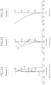
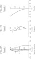
- Fig. 7A shows each spherical aberration of d-line, F-line, and C-line for the imaging lens 10 of Example 1.
- Fig. 7B shows the astigmatism S in the sagittal (radical) direction and the astigmatism T in the tangential (meridional) direction of the d line for the imaging lens 10 of Example 1.
- Fig. 7C shows the distortion of the imaging lens 10 of Example 1.
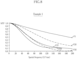
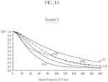
- Fig. 8 shows the MTF of Example 1 at 22 °C.
- the reference numeral F1 indicates the MTF on the optical axis Z1.
- the reference numeral F2R indicates the MTF in the sagittal direction at a point 26 degrees from the optical axis Z1.
- the reference numeral F2T indicates the MTF in the tangential direction at the point 26 degrees from the optical axis Z1.
- the reference numeral F3R indicates the MTF in the sagittal direction at a point 60 degrees from the optical axis Z1.
- the reference numeral F3T indicates the MTF in the tangential direction at the point 60 degrees from the optical axis Z1.
- the imaging lens 10 of Example 1 suppresses ghosting caused by reflected light and has excellent optical performance, though it has the simple configuration of 6 elements in 5 groups and has the infrared ray cutting function with the infrared ray cut coat.
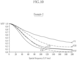
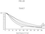
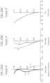
- Example 1 the various lens data for the imaging lenses 2 to 10 are shown in Tables 5 to 31, and spherical aberration, astigmatism, distortion, and MTF are shown in Figs. 9A to 26 .
Landscapes
- Physics & Mathematics (AREA)
- General Physics & Mathematics (AREA)
- Optics & Photonics (AREA)
- Lenses (AREA)
Claims (7)
- Abbildungslinse (10), aufweisend in einer Reihenfolge von einer Objektseite aus:eine vordere Gruppe (G1), die eine negative Brechkraft hat,eine Aperturblende (ST) undeine hintere Gruppe (G2), die eine positive Brechkraft hat,wobei in der vorderen Gruppe (G1) eine erste Linsenfläche (S1), die der Objektseite am nächsten ist, eine konvexe Form in Richtung zu der Objektseite hat,wobei in der hinteren Gruppe (G2) eine zweite Linsenfläche (S6), die der Objektseite am nächsten ist, eine konvexe Form in Richtung zu der Objektseite hat, eine dritte Linsenfläche (S12), die einer Bildseite am nächsten ist, eine konvexe Form in Richtung zu der Bildseite hat, und die dritte Linsenfläche (S12) eine Infrarotstrahl-Cut/Reduzier-Beschichtung (IR) hat,wobei ein Krümmungsradius der zweiten Linsenfläche (S6) durch Rr dargestellt ist, ein Krümmungsradius der dritten Linsenfläche (S12) durch Re dargestellt ist, ein Abstand von der zweiten Linsenfläche (S6) zu der dritten Linsenfläche (12) auf einer optischen Achse (Z1) durch Da dargestellt ist und die folgende Bedingung (1) erfüllt ist:
 wobei(i) die vordere Gruppe (G1) aufweist: eine konkave meniskusförmige erste Linse (L1), die die erste Linsenfläche (S1) aufweist, und eine konkave meniskusförmige zweite Linse (L2) in einer Reihenfolge von der Objektseite aus, und die zweite Linse (L2) mit ihrer konvexen Fläche der Bildseite zugewandt angeordnet ist
und/oder(ii) die hintere Gruppe (G2) aufweist: eine dritte Linse (L3), die die zweite Linsenfläche (S6) aufweist, eine vierte Linse (L4) und eine verkittete Linse (CL) in einer Reihenfolge von der Objektseite aus, und wobei die dritte Linse (L3), die vierte Linse (L4) und die verkittete Linse (CL) alle eine positive Brechkraft haben. - Abbildungslinse (10) gemäß Anspruch 1,
wobei in dem Umfang, in dem die hintere Gruppe (G2) die dritte Linse (L3), die die zweite Linsenfläche (S6) aufweist, die vierte Linse (L4) und die verkittete Linse (CL) in einer Reihenfolge von der Objektseite aus aufweist, und in dem Umfang, in dem die dritte Linse (L3), die vierte Linse (L4) und die verkittete Linse (CL) alle eine positive Brechkraft haben: die verkittete Linse (CL) aus einer fünften Linse (L5), die eine konkave Linse ist, und einer sechsten Linse (L6), die eine konvexe Linse ist, in einer Reihenfolge von der Objektseite aus zusammengesetzt ist, und die sechste Linse (L6) die dritte Linsenfläche (S12) aufweist. - Abbildungslinse (10) gemäß Anspruch 1 oder 2,
wobei ein Krümmungsradius der ersten Linsenfläche (S1) durch R1 dargestellt ist, der Krümmungsradius der dritten Linsenfläche (12) durch Re dargestellt ist, ein Abstand von der ersten Linsenfläche (S1) zu der dritten Linsenfläche (12) auf der optischen Achse (Z1) durch Dt dargestellt ist und die folgende Bedingung (2) erfüllt ist:
- Abbildungsvorrichtung (20), aufweisend in einer Reihenfolge von einer Objektseite aus:die Abbildungslinse (10) gemäß irgendeinem der Ansprüche 1 bis 3 undein flaches, plattenförmiges Deckglas (CG).
- Abbildungsvorrichtung (20) gemäß Anspruch 4,
wobei der Krümmungsradius der ersten Linsenfläche (S1) durch R1 dargestellt ist, der Abstand von der ersten Linsenfläche (S1) zu der dritten Linsenfläche (12) auf der optischen Achse (Z1) durch Dt dargestellt ist, der Abstand von der dritten Linsenfläche (12) zu der Objektseite des Deckglases (CG) auf der optischen Achse (Z1) durch Db dargestellt ist und die folgende Bedingung (3) erfüllt ist:
- Abbildungsvorrichtung (20) gemäß Anspruch 4 oder 5,
wobei der Krümmungsradius der zweiten Linsenfläche (S6) durch Rr dargestellt ist, der Abstand von der zweiten Linsenfläche (S6) zu der dritten Linsenfläche (12) auf der optischen Achse (Z1) durch Da dargestellt ist, der Abstand von der dritten Linsenfläche (12) zu der Objektseite des Deckglases (CG) auf der optischen Achse (Zl) durch Db dargestellt ist und die folgende Bedingung (4) erfüllt ist:
- Abbildungsvorrichtung (20) gemäß einem der Ansprüche 4 bis 6,
wobei der Krümmungsradius der dritten Linsenfläche (12) der Linse durch Re dargestellt ist, der Abstand von der dritten Linsenfläche (12) zu der Objektseite des Deckglases (CG) auf der optischen Achse (Z1) durch Db dargestellt ist und die folgende Bedingung (5) erfüllt ist:
Applications Claiming Priority (2)
| Application Number | Priority Date | Filing Date | Title |
|---|---|---|---|
| JP2019119161 | 2019-06-26 | ||
| PCT/JP2020/025089 WO2020262553A1 (ja) | 2019-06-26 | 2020-06-25 | 撮像レンズ及び撮像装置 |
Publications (3)
| Publication Number | Publication Date |
|---|---|
| EP3974886A1 EP3974886A1 (de) | 2022-03-30 |
| EP3974886A4 EP3974886A4 (de) | 2022-08-17 |
| EP3974886B1 true EP3974886B1 (de) | 2025-02-12 |
Family
ID=74059910
Family Applications (1)
| Application Number | Title | Priority Date | Filing Date |
|---|---|---|---|
| EP20831984.8A Active EP3974886B1 (de) | 2019-06-26 | 2020-06-25 | Bildgebungslinse und bildaufnahmevorrichtung |
Country Status (5)
| Country | Link |
|---|---|
| US (1) | US12253658B2 (de) |
| EP (1) | EP3974886B1 (de) |
| JP (1) | JP7662517B2 (de) |
| CN (1) | CN114051590B (de) |
| WO (1) | WO2020262553A1 (de) |
Families Citing this family (3)
| Publication number | Priority date | Publication date | Assignee | Title |
|---|---|---|---|---|
| CN112987144B (zh) * | 2021-03-29 | 2023-04-21 | 维沃移动通信有限公司 | 镜头、摄像模组和电子设备 |
| CN112987143B (zh) * | 2021-03-29 | 2023-03-31 | 维沃移动通信有限公司 | 镜头、摄像模组和电子设备 |
| CN118131441A (zh) | 2024-02-06 | 2024-06-04 | 常州市瑞泰光电有限公司 | 摄像光学镜头 |
Family Cites Families (30)
| Publication number | Priority date | Publication date | Assignee | Title |
|---|---|---|---|---|
| JPH08122634A (ja) * | 1994-10-25 | 1996-05-17 | Asahi Optical Co Ltd | 内視鏡用対物レンズ |
| US5828498A (en) | 1994-10-25 | 1998-10-27 | Asahi Kogaku Kogyo Kabushiki Kaisha | Objective lens of endoscope |
| JP2004088181A (ja) * | 2002-08-23 | 2004-03-18 | Kawaguchiko Seimitsu Co Ltd | 小型撮像モジュール |
| JP2006011093A (ja) * | 2004-06-25 | 2006-01-12 | Konica Minolta Opto Inc | 超広角光学系、撮像装置、車載カメラ及びデジタル機器 |
| JP4756901B2 (ja) * | 2005-04-25 | 2011-08-24 | キヤノン株式会社 | 接眼レンズ及びそれを用いた光学機器 |
| JP2008133267A (ja) | 2006-10-30 | 2008-06-12 | Sumitomo Chemical Co Ltd | 水稲吸汁性害虫による水稲被害を抑制する方法 |
| JP3964932B1 (ja) | 2007-01-24 | 2007-08-22 | 公二 宇野 | 錠保持機能付き自転車用フェンダー |
| JP2010145828A (ja) | 2008-12-19 | 2010-07-01 | Tamron Co Ltd | 撮像レンズ |
| EP2474851B1 (de) | 2009-09-01 | 2016-12-14 | Olympus Corporation | Optisches objektivsystem |
| EP2397880B1 (de) * | 2010-06-16 | 2017-04-12 | Ricoh Company, Ltd. | Bilderzeugungslinse und Kameravorrichtung und tragbare Informationsendgerätevorrichtung mit der Bilderzeugungslinse |
| US8780463B2 (en) * | 2010-06-24 | 2014-07-15 | Ricoh Company, Ltd. | Image-forming lens, and imaging apparatus and information device using the image-forming lens |
| KR101910411B1 (ko) * | 2011-06-07 | 2018-10-22 | 엘지이노텍 주식회사 | 촬상 렌즈 및 카메라 모듈 |
| JP5687572B2 (ja) * | 2011-06-14 | 2015-03-18 | オリンパス株式会社 | 結像光学系及びそれを備えた内視鏡装置 |
| CN203688899U (zh) * | 2011-07-28 | 2014-07-02 | 富士胶片株式会社 | 成像镜头和使用该成像镜头的成像设备 |
| JP5633937B2 (ja) * | 2011-09-29 | 2014-12-03 | 富士フイルム株式会社 | 撮像レンズおよび撮像装置 |
| WO2013099213A1 (ja) * | 2011-12-27 | 2013-07-04 | 富士フイルム株式会社 | 撮像レンズおよび撮像装置 |
| KR102047375B1 (ko) * | 2012-05-07 | 2019-11-21 | 엘지이노텍 주식회사 | 카메라 모듈 |
| WO2014006842A1 (ja) * | 2012-07-05 | 2014-01-09 | 富士フイルム株式会社 | 広角レンズおよび撮像装置 |
| WO2014054407A1 (ja) * | 2012-10-02 | 2014-04-10 | オリンパスメディカルシステムズ株式会社 | 内視鏡対物光学系 |
| KR101429887B1 (ko) * | 2013-03-22 | 2014-08-13 | 주식회사 세코닉스 | 소형 광각 렌즈 시스템 |
| JP6253379B2 (ja) * | 2013-12-06 | 2017-12-27 | キヤノン株式会社 | 光学系及びそれを有する撮像装置 |
| JP6145887B2 (ja) * | 2014-03-12 | 2017-06-14 | 富士フイルム株式会社 | 撮像レンズおよび撮像装置 |
| JP6066424B2 (ja) * | 2014-03-12 | 2017-01-25 | 富士フイルム株式会社 | 撮像レンズおよび撮像装置 |
| US10139595B1 (en) * | 2014-03-16 | 2018-11-27 | Navitar Industries, Llc | Optical assembly for a compact wide field of view digital camera with low first lens diameter to image diagonal ratio |
| WO2016190184A1 (ja) * | 2015-05-28 | 2016-12-01 | オリンパス株式会社 | 内視鏡対物光学系 |
| JP6732411B2 (ja) * | 2015-06-26 | 2020-07-29 | 京セラ株式会社 | 撮像レンズおよび撮像装置 |
| TWI616678B (zh) * | 2016-12-20 | 2018-03-01 | 大立光電股份有限公司 | 影像擷取鏡片系統、取像裝置及電子裝置 |
| EP3605180B1 (de) | 2017-04-26 | 2021-11-17 | Kyocera Corporation | Bildgebungslinse |
| JP2019066645A (ja) * | 2017-09-29 | 2019-04-25 | 日本電産サンキョー株式会社 | 広角レンズ |
| JP7020938B2 (ja) * | 2018-01-31 | 2022-02-16 | 株式会社タムロン | 撮像レンズ及び撮像装置 |
-
2020
- 2020-06-25 EP EP20831984.8A patent/EP3974886B1/de active Active
- 2020-06-25 CN CN202080046246.6A patent/CN114051590B/zh active Active
- 2020-06-25 WO PCT/JP2020/025089 patent/WO2020262553A1/ja not_active Ceased
- 2020-06-25 JP JP2021527742A patent/JP7662517B2/ja active Active
-
2021
- 2021-12-23 US US17/561,628 patent/US12253658B2/en active Active
Also Published As
| Publication number | Publication date |
|---|---|
| JP7662517B2 (ja) | 2025-04-15 |
| CN114051590B (zh) | 2024-06-21 |
| EP3974886A4 (de) | 2022-08-17 |
| CN114051590A (zh) | 2022-02-15 |
| US12253658B2 (en) | 2025-03-18 |
| US20220121017A1 (en) | 2022-04-21 |
| EP3974886A1 (de) | 2022-03-30 |
| WO2020262553A1 (ja) | 2020-12-30 |
| JPWO2020262553A1 (de) | 2020-12-30 |
Similar Documents
| Publication | Publication Date | Title |
|---|---|---|
| CN112166362B (zh) | 成像透镜及摄像装置 | |
| CN113640971B (zh) | 摄像镜头 | |
| US10073252B2 (en) | Optical system and image pickup apparatus including the same | |
| US7453654B2 (en) | Imaging lens | |
| US9465201B2 (en) | Imaging lens and imaging apparatus | |
| JP4561634B2 (ja) | 撮像レンズ及び撮像装置 | |
| US6977779B2 (en) | Imaging lens | |
| JP7075441B2 (ja) | 撮像レンズ | |
| CN109164557B (zh) | 广角镜头及全景摄像系统 | |
| US11054630B2 (en) | Camera lens system for an endoscope, method for producing a camera lens system and an endoscope | |
| US7538958B2 (en) | Wide-angle lens | |
| CN110716288B (zh) | 光学成像镜头 | |
| EP2256533A1 (de) | Abbildungslinse und Bildaufnahmevorrichtung | |
| US12253658B2 (en) | Imaging lens and imaging apparatus | |
| EP3796055B1 (de) | Optisches system und bildaufnahmevorrichtung damit | |
| JP2006162829A (ja) | 広角撮像レンズ及び撮像装置 | |
| CN112305712A (zh) | 摄像镜头 | |
| EP3252522A1 (de) | Linsenvorrichtung und bildaufnahmevorrichtung damit | |
| EP4270082A1 (de) | Abbildungslinse | |
| JP6868424B2 (ja) | 撮像レンズ | |
| JP7810838B2 (ja) | 撮像レンズ系及び撮像装置 | |
| JP2009086589A (ja) | 撮像レンズ | |
| JP2001183582A (ja) | 明るく広角な赤外線レンズ | |
| JP2019179180A (ja) | 撮像レンズユニット | |
| JP3409248B2 (ja) | 広角レンズ |
Legal Events
| Date | Code | Title | Description |
|---|---|---|---|
| STAA | Information on the status of an ep patent application or granted ep patent |
Free format text: STATUS: THE INTERNATIONAL PUBLICATION HAS BEEN MADE |
|
| PUAI | Public reference made under article 153(3) epc to a published international application that has entered the european phase |
Free format text: ORIGINAL CODE: 0009012 |
|
| STAA | Information on the status of an ep patent application or granted ep patent |
Free format text: STATUS: REQUEST FOR EXAMINATION WAS MADE |
|
| 17P | Request for examination filed |
Effective date: 20211223 |
|
| AK | Designated contracting states |
Kind code of ref document: A1 Designated state(s): AL AT BE BG CH CY CZ DE DK EE ES FI FR GB GR HR HU IE IS IT LI LT LU LV MC MK MT NL NO PL PT RO RS SE SI SK SM TR |
|
| A4 | Supplementary search report drawn up and despatched |
Effective date: 20220718 |
|
| RIC1 | Information provided on ipc code assigned before grant |
Ipc: G02B 9/10 20060101ALN20220712BHEP Ipc: G02B 27/00 20060101ALI20220712BHEP Ipc: G02B 9/62 20060101ALI20220712BHEP Ipc: G02B 9/60 20060101ALI20220712BHEP Ipc: G02B 13/04 20060101AFI20220712BHEP |
|
| DAV | Request for validation of the european patent (deleted) | ||
| DAX | Request for extension of the european patent (deleted) | ||
| P01 | Opt-out of the competence of the unified patent court (upc) registered |
Effective date: 20230505 |
|
| GRAP | Despatch of communication of intention to grant a patent |
Free format text: ORIGINAL CODE: EPIDOSNIGR1 |
|
| STAA | Information on the status of an ep patent application or granted ep patent |
Free format text: STATUS: GRANT OF PATENT IS INTENDED |
|
| INTG | Intention to grant announced |
Effective date: 20240830 |
|
| GRAS | Grant fee paid |
Free format text: ORIGINAL CODE: EPIDOSNIGR3 |
|
| GRAA | (expected) grant |
Free format text: ORIGINAL CODE: 0009210 |
|
| STAA | Information on the status of an ep patent application or granted ep patent |
Free format text: STATUS: THE PATENT HAS BEEN GRANTED |
|
| AK | Designated contracting states |
Kind code of ref document: B1 Designated state(s): AL AT BE BG CH CY CZ DE DK EE ES FI FR GB GR HR HU IE IS IT LI LT LU LV MC MK MT NL NO PL PT RO RS SE SI SK SM TR |
|
| REG | Reference to a national code |
Ref country code: GB Ref legal event code: FG4D |
|
| REG | Reference to a national code |
Ref country code: CH Ref legal event code: EP |
|
| REG | Reference to a national code |
Ref country code: DE Ref legal event code: R096 Ref document number: 602020046043 Country of ref document: DE |
|
| REG | Reference to a national code |
Ref country code: IE Ref legal event code: FG4D |
|
| REG | Reference to a national code |
Ref country code: NL Ref legal event code: MP Effective date: 20250212 |
|
| PG25 | Lapsed in a contracting state [announced via postgrant information from national office to epo] |
Ref country code: RS Free format text: LAPSE BECAUSE OF FAILURE TO SUBMIT A TRANSLATION OF THE DESCRIPTION OR TO PAY THE FEE WITHIN THE PRESCRIBED TIME-LIMIT Effective date: 20250512 |
|
| PG25 | Lapsed in a contracting state [announced via postgrant information from national office to epo] |
Ref country code: FI Free format text: LAPSE BECAUSE OF FAILURE TO SUBMIT A TRANSLATION OF THE DESCRIPTION OR TO PAY THE FEE WITHIN THE PRESCRIBED TIME-LIMIT Effective date: 20250212 |
|
| PG25 | Lapsed in a contracting state [announced via postgrant information from national office to epo] |
Ref country code: PL Free format text: LAPSE BECAUSE OF FAILURE TO SUBMIT A TRANSLATION OF THE DESCRIPTION OR TO PAY THE FEE WITHIN THE PRESCRIBED TIME-LIMIT Effective date: 20250212 |
|
| PGFP | Annual fee paid to national office [announced via postgrant information from national office to epo] |
Ref country code: DE Payment date: 20250429 Year of fee payment: 6 |
|
| PG25 | Lapsed in a contracting state [announced via postgrant information from national office to epo] |
Ref country code: ES Free format text: LAPSE BECAUSE OF FAILURE TO SUBMIT A TRANSLATION OF THE DESCRIPTION OR TO PAY THE FEE WITHIN THE PRESCRIBED TIME-LIMIT Effective date: 20250212 |
|
| PGFP | Annual fee paid to national office [announced via postgrant information from national office to epo] |
Ref country code: GB Payment date: 20250501 Year of fee payment: 6 |
|
| REG | Reference to a national code |
Ref country code: LT Ref legal event code: MG9D |
|
| PG25 | Lapsed in a contracting state [announced via postgrant information from national office to epo] |
Ref country code: IS Free format text: LAPSE BECAUSE OF FAILURE TO SUBMIT A TRANSLATION OF THE DESCRIPTION OR TO PAY THE FEE WITHIN THE PRESCRIBED TIME-LIMIT Effective date: 20250612 Ref country code: NO Free format text: LAPSE BECAUSE OF FAILURE TO SUBMIT A TRANSLATION OF THE DESCRIPTION OR TO PAY THE FEE WITHIN THE PRESCRIBED TIME-LIMIT Effective date: 20250512 |
|
| PG25 | Lapsed in a contracting state [announced via postgrant information from national office to epo] |
Ref country code: NL Free format text: LAPSE BECAUSE OF FAILURE TO SUBMIT A TRANSLATION OF THE DESCRIPTION OR TO PAY THE FEE WITHIN THE PRESCRIBED TIME-LIMIT Effective date: 20250212 |
|
| PG25 | Lapsed in a contracting state [announced via postgrant information from national office to epo] |
Ref country code: HR Free format text: LAPSE BECAUSE OF FAILURE TO SUBMIT A TRANSLATION OF THE DESCRIPTION OR TO PAY THE FEE WITHIN THE PRESCRIBED TIME-LIMIT Effective date: 20250212 |
|
| PG25 | Lapsed in a contracting state [announced via postgrant information from national office to epo] |
Ref country code: LV Free format text: LAPSE BECAUSE OF FAILURE TO SUBMIT A TRANSLATION OF THE DESCRIPTION OR TO PAY THE FEE WITHIN THE PRESCRIBED TIME-LIMIT Effective date: 20250212 Ref country code: PT Free format text: LAPSE BECAUSE OF FAILURE TO SUBMIT A TRANSLATION OF THE DESCRIPTION OR TO PAY THE FEE WITHIN THE PRESCRIBED TIME-LIMIT Effective date: 20250612 |
|
| PGFP | Annual fee paid to national office [announced via postgrant information from national office to epo] |
Ref country code: FR Payment date: 20250508 Year of fee payment: 6 |
|
| PG25 | Lapsed in a contracting state [announced via postgrant information from national office to epo] |
Ref country code: GR Free format text: LAPSE BECAUSE OF FAILURE TO SUBMIT A TRANSLATION OF THE DESCRIPTION OR TO PAY THE FEE WITHIN THE PRESCRIBED TIME-LIMIT Effective date: 20250513 Ref country code: BG Free format text: LAPSE BECAUSE OF FAILURE TO SUBMIT A TRANSLATION OF THE DESCRIPTION OR TO PAY THE FEE WITHIN THE PRESCRIBED TIME-LIMIT Effective date: 20250212 |
|
| REG | Reference to a national code |
Ref country code: AT Ref legal event code: MK05 Ref document number: 1766577 Country of ref document: AT Kind code of ref document: T Effective date: 20250212 |
|
| PG25 | Lapsed in a contracting state [announced via postgrant information from national office to epo] |
Ref country code: SE Free format text: LAPSE BECAUSE OF FAILURE TO SUBMIT A TRANSLATION OF THE DESCRIPTION OR TO PAY THE FEE WITHIN THE PRESCRIBED TIME-LIMIT Effective date: 20250212 |
|
| PG25 | Lapsed in a contracting state [announced via postgrant information from national office to epo] |
Ref country code: SM Free format text: LAPSE BECAUSE OF FAILURE TO SUBMIT A TRANSLATION OF THE DESCRIPTION OR TO PAY THE FEE WITHIN THE PRESCRIBED TIME-LIMIT Effective date: 20250212 |
|
| PG25 | Lapsed in a contracting state [announced via postgrant information from national office to epo] |
Ref country code: DK Free format text: LAPSE BECAUSE OF FAILURE TO SUBMIT A TRANSLATION OF THE DESCRIPTION OR TO PAY THE FEE WITHIN THE PRESCRIBED TIME-LIMIT Effective date: 20250212 |
|
| PG25 | Lapsed in a contracting state [announced via postgrant information from national office to epo] |
Ref country code: IT Free format text: LAPSE BECAUSE OF FAILURE TO SUBMIT A TRANSLATION OF THE DESCRIPTION OR TO PAY THE FEE WITHIN THE PRESCRIBED TIME-LIMIT Effective date: 20250212 |
|
| PG25 | Lapsed in a contracting state [announced via postgrant information from national office to epo] |
Ref country code: AT Free format text: LAPSE BECAUSE OF FAILURE TO SUBMIT A TRANSLATION OF THE DESCRIPTION OR TO PAY THE FEE WITHIN THE PRESCRIBED TIME-LIMIT Effective date: 20250212 |
|
| PG25 | Lapsed in a contracting state [announced via postgrant information from national office to epo] |
Ref country code: CZ Free format text: LAPSE BECAUSE OF FAILURE TO SUBMIT A TRANSLATION OF THE DESCRIPTION OR TO PAY THE FEE WITHIN THE PRESCRIBED TIME-LIMIT Effective date: 20250212 Ref country code: EE Free format text: LAPSE BECAUSE OF FAILURE TO SUBMIT A TRANSLATION OF THE DESCRIPTION OR TO PAY THE FEE WITHIN THE PRESCRIBED TIME-LIMIT Effective date: 20250212 |
|
| PG25 | Lapsed in a contracting state [announced via postgrant information from national office to epo] |
Ref country code: RO Free format text: LAPSE BECAUSE OF FAILURE TO SUBMIT A TRANSLATION OF THE DESCRIPTION OR TO PAY THE FEE WITHIN THE PRESCRIBED TIME-LIMIT Effective date: 20250212 |
|
| PG25 | Lapsed in a contracting state [announced via postgrant information from national office to epo] |
Ref country code: SK Free format text: LAPSE BECAUSE OF FAILURE TO SUBMIT A TRANSLATION OF THE DESCRIPTION OR TO PAY THE FEE WITHIN THE PRESCRIBED TIME-LIMIT Effective date: 20250212 |
|
| REG | Reference to a national code |
Ref country code: DE Ref legal event code: R097 Ref document number: 602020046043 Country of ref document: DE |
|
| PLBE | No opposition filed within time limit |
Free format text: ORIGINAL CODE: 0009261 |
|
| STAA | Information on the status of an ep patent application or granted ep patent |
Free format text: STATUS: NO OPPOSITION FILED WITHIN TIME LIMIT |
|
| REG | Reference to a national code |
Ref country code: CH Ref legal event code: L10 Free format text: ST27 STATUS EVENT CODE: U-0-0-L10-L00 (AS PROVIDED BY THE NATIONAL OFFICE) Effective date: 20251224 |
|
| 26N | No opposition filed |
Effective date: 20251113 |
|
| REG | Reference to a national code |
Ref country code: CH Ref legal event code: H13 Free format text: ST27 STATUS EVENT CODE: U-0-0-H10-H13 (AS PROVIDED BY THE NATIONAL OFFICE) Effective date: 20260127 |
|
| PG25 | Lapsed in a contracting state [announced via postgrant information from national office to epo] |
Ref country code: MC Free format text: LAPSE BECAUSE OF FAILURE TO SUBMIT A TRANSLATION OF THE DESCRIPTION OR TO PAY THE FEE WITHIN THE PRESCRIBED TIME-LIMIT Effective date: 20250212 |
|
| PG25 | Lapsed in a contracting state [announced via postgrant information from national office to epo] |
Ref country code: LU Free format text: LAPSE BECAUSE OF NON-PAYMENT OF DUE FEES Effective date: 20250625 |
|
| REG | Reference to a national code |
Ref country code: BE Ref legal event code: MM Effective date: 20250630 |
|
| PG25 | Lapsed in a contracting state [announced via postgrant information from national office to epo] |
Ref country code: IE Free format text: LAPSE BECAUSE OF NON-PAYMENT OF DUE FEES Effective date: 20250625 |
|
| PG25 | Lapsed in a contracting state [announced via postgrant information from national office to epo] |
Ref country code: BE Free format text: LAPSE BECAUSE OF NON-PAYMENT OF DUE FEES Effective date: 20250630 |
|
| PG25 | Lapsed in a contracting state [announced via postgrant information from national office to epo] |
Ref country code: CH Free format text: LAPSE BECAUSE OF NON-PAYMENT OF DUE FEES Effective date: 20250630 |