EP3974850B1 - Vorrichtung und verfahren zur diagnose eines parallelbatterierelais - Google Patents
Vorrichtung und verfahren zur diagnose eines parallelbatterierelais Download PDFInfo
- Publication number
- EP3974850B1 EP3974850B1 EP20902610.3A EP20902610A EP3974850B1 EP 3974850 B1 EP3974850 B1 EP 3974850B1 EP 20902610 A EP20902610 A EP 20902610A EP 3974850 B1 EP3974850 B1 EP 3974850B1
- Authority
- EP
- European Patent Office
- Prior art keywords
- switch
- battery
- battery packs
- cell module
- terminal
- Prior art date
- Legal status (The legal status is an assumption and is not a legal conclusion. Google has not performed a legal analysis and makes no representation as to the accuracy of the status listed.)
- Active
Links
Images


Classifications
-
- G—PHYSICS
- G01—MEASURING; TESTING
- G01R—MEASURING ELECTRIC VARIABLES; MEASURING MAGNETIC VARIABLES
- G01R31/00—Arrangements for testing electric properties; Arrangements for locating electric faults; Arrangements for electrical testing characterised by what is being tested not provided for elsewhere
- G01R31/327—Testing of circuit interrupters, switches or circuit-breakers
- G01R31/3277—Testing of circuit interrupters, switches or circuit-breakers of low voltage devices, e.g. domestic or industrial devices, such as motor protections, relays, rotation switches
- G01R31/3278—Testing of circuit interrupters, switches or circuit-breakers of low voltage devices, e.g. domestic or industrial devices, such as motor protections, relays, rotation switches of relays, solenoids or reed switches
-
- G—PHYSICS
- G01—MEASURING; TESTING
- G01R—MEASURING ELECTRIC VARIABLES; MEASURING MAGNETIC VARIABLES
- G01R31/00—Arrangements for testing electric properties; Arrangements for locating electric faults; Arrangements for electrical testing characterised by what is being tested not provided for elsewhere
- G01R31/36—Arrangements for testing, measuring or monitoring the electrical condition of accumulators or electric batteries, e.g. capacity or state of charge [SoC]
-
- H—ELECTRICITY
- H01—ELECTRIC ELEMENTS
- H01M—PROCESSES OR MEANS, e.g. BATTERIES, FOR THE DIRECT CONVERSION OF CHEMICAL ENERGY INTO ELECTRICAL ENERGY
- H01M10/00—Secondary cells; Manufacture thereof
- H01M10/42—Methods or arrangements for servicing or maintenance of secondary cells or secondary half-cells
- H01M10/425—Structural combination with electronic components, e.g. electronic circuits integrated to the outside of the casing
- H01M10/4257—Smart batteries, e.g. electronic circuits inside the housing of the cells or batteries
-
- H—ELECTRICITY
- H01—ELECTRIC ELEMENTS
- H01M—PROCESSES OR MEANS, e.g. BATTERIES, FOR THE DIRECT CONVERSION OF CHEMICAL ENERGY INTO ELECTRICAL ENERGY
- H01M10/00—Secondary cells; Manufacture thereof
- H01M10/42—Methods or arrangements for servicing or maintenance of secondary cells or secondary half-cells
- H01M10/48—Accumulators combined with arrangements for measuring, testing or indicating the condition of cells, e.g. the level or density of the electrolyte
- H01M10/482—Accumulators combined with arrangements for measuring, testing or indicating the condition of cells, e.g. the level or density of the electrolyte for several batteries or cells simultaneously or sequentially
-
- H—ELECTRICITY
- H01—ELECTRIC ELEMENTS
- H01M—PROCESSES OR MEANS, e.g. BATTERIES, FOR THE DIRECT CONVERSION OF CHEMICAL ENERGY INTO ELECTRICAL ENERGY
- H01M10/00—Secondary cells; Manufacture thereof
- H01M10/42—Methods or arrangements for servicing or maintenance of secondary cells or secondary half-cells
- H01M10/48—Accumulators combined with arrangements for measuring, testing or indicating the condition of cells, e.g. the level or density of the electrolyte
- H01M10/488—Cells or batteries combined with indicating means for external visualization of the condition, e.g. by change of colour or of light density
-
- H—ELECTRICITY
- H01—ELECTRIC ELEMENTS
- H01M—PROCESSES OR MEANS, e.g. BATTERIES, FOR THE DIRECT CONVERSION OF CHEMICAL ENERGY INTO ELECTRICAL ENERGY
- H01M50/00—Constructional details or processes of manufacture of the non-active parts of electrochemical cells other than fuel cells, e.g. hybrid cells
- H01M50/50—Current conducting connections for cells or batteries
- H01M50/502—Interconnectors for connecting terminals of adjacent batteries; Interconnectors for connecting cells outside a battery casing
- H01M50/509—Interconnectors for connecting terminals of adjacent batteries; Interconnectors for connecting cells outside a battery casing characterised by the type of connection, e.g. mixed connections
- H01M50/512—Connection only in parallel
-
- H—ELECTRICITY
- H01—ELECTRIC ELEMENTS
- H01M—PROCESSES OR MEANS, e.g. BATTERIES, FOR THE DIRECT CONVERSION OF CHEMICAL ENERGY INTO ELECTRICAL ENERGY
- H01M50/00—Constructional details or processes of manufacture of the non-active parts of electrochemical cells other than fuel cells, e.g. hybrid cells
- H01M50/50—Current conducting connections for cells or batteries
- H01M50/569—Constructional details of current conducting connections for detecting conditions inside cells or batteries, e.g. details of voltage sensing terminals
-
- H—ELECTRICITY
- H02—GENERATION; CONVERSION OR DISTRIBUTION OF ELECTRIC POWER
- H02J—CIRCUIT ARRANGEMENTS OR SYSTEMS FOR SUPPLYING OR DISTRIBUTING ELECTRIC POWER; SYSTEMS FOR STORING ELECTRIC ENERGY
- H02J7/00—Circuit arrangements for charging or depolarising batteries or for supplying loads from batteries
- H02J7/0013—Circuit arrangements for charging or depolarising batteries or for supplying loads from batteries acting upon several batteries simultaneously or sequentially
-
- H—ELECTRICITY
- H02—GENERATION; CONVERSION OR DISTRIBUTION OF ELECTRIC POWER
- H02J—CIRCUIT ARRANGEMENTS OR SYSTEMS FOR SUPPLYING OR DISTRIBUTING ELECTRIC POWER; SYSTEMS FOR STORING ELECTRIC ENERGY
- H02J7/00—Circuit arrangements for charging or depolarising batteries or for supplying loads from batteries
- H02J7/0029—Circuit arrangements for charging or depolarising batteries or for supplying loads from batteries with safety or protection devices or circuits
- H02J7/0031—Circuit arrangements for charging or depolarising batteries or for supplying loads from batteries with safety or protection devices or circuits using battery or load disconnect circuits
-
- H—ELECTRICITY
- H02—GENERATION; CONVERSION OR DISTRIBUTION OF ELECTRIC POWER
- H02J—CIRCUIT ARRANGEMENTS OR SYSTEMS FOR SUPPLYING OR DISTRIBUTING ELECTRIC POWER; SYSTEMS FOR STORING ELECTRIC ENERGY
- H02J7/00—Circuit arrangements for charging or depolarising batteries or for supplying loads from batteries
- H02J7/0029—Circuit arrangements for charging or depolarising batteries or for supplying loads from batteries with safety or protection devices or circuits
- H02J7/0036—Circuit arrangements for charging or depolarising batteries or for supplying loads from batteries with safety or protection devices or circuits using connection detecting circuits
-
- H—ELECTRICITY
- H02—GENERATION; CONVERSION OR DISTRIBUTION OF ELECTRIC POWER
- H02J—CIRCUIT ARRANGEMENTS OR SYSTEMS FOR SUPPLYING OR DISTRIBUTING ELECTRIC POWER; SYSTEMS FOR STORING ELECTRIC ENERGY
- H02J7/00—Circuit arrangements for charging or depolarising batteries or for supplying loads from batteries
- H02J7/0047—Circuit arrangements for charging or depolarising batteries or for supplying loads from batteries with monitoring or indicating devices or circuits
-
- H—ELECTRICITY
- H02—GENERATION; CONVERSION OR DISTRIBUTION OF ELECTRIC POWER
- H02J—CIRCUIT ARRANGEMENTS OR SYSTEMS FOR SUPPLYING OR DISTRIBUTING ELECTRIC POWER; SYSTEMS FOR STORING ELECTRIC ENERGY
- H02J7/00—Circuit arrangements for charging or depolarising batteries or for supplying loads from batteries
- H02J7/0068—Battery or charger load switching, e.g. concurrent charging and load supply
-
- H—ELECTRICITY
- H01—ELECTRIC ELEMENTS
- H01M—PROCESSES OR MEANS, e.g. BATTERIES, FOR THE DIRECT CONVERSION OF CHEMICAL ENERGY INTO ELECTRICAL ENERGY
- H01M10/00—Secondary cells; Manufacture thereof
- H01M10/42—Methods or arrangements for servicing or maintenance of secondary cells or secondary half-cells
- H01M10/425—Structural combination with electronic components, e.g. electronic circuits integrated to the outside of the casing
- H01M2010/4271—Battery management systems including electronic circuits, e.g. control of current or voltage to keep battery in healthy state, cell balancing
-
- Y—GENERAL TAGGING OF NEW TECHNOLOGICAL DEVELOPMENTS; GENERAL TAGGING OF CROSS-SECTIONAL TECHNOLOGIES SPANNING OVER SEVERAL SECTIONS OF THE IPC; TECHNICAL SUBJECTS COVERED BY FORMER USPC CROSS-REFERENCE ART COLLECTIONS [XRACs] AND DIGESTS
- Y02—TECHNOLOGIES OR APPLICATIONS FOR MITIGATION OR ADAPTATION AGAINST CLIMATE CHANGE
- Y02E—REDUCTION OF GREENHOUSE GAS [GHG] EMISSIONS, RELATED TO ENERGY GENERATION, TRANSMISSION OR DISTRIBUTION
- Y02E60/00—Enabling technologies; Technologies with a potential or indirect contribution to GHG emissions mitigation
- Y02E60/10—Energy storage using batteries
Definitions
- the present disclosure relates to a device and method for diagnosing a relay of a plurality of battery packs connected in parallel.
- the secondary battery is a battery capable of recharging and discharging, and in its meaning, includes all of the existing Ni/Cd battery, the Ni/MH battery, and the like and a recent lithium-ion battery.
- lithium-ion batteries have the advantage of having much higher energy density than the existing Ni/Cd batteries and Ni/MH batteries.
- lithium-ion batteries may be manufactured in a small size and light weight, and accordingly, may be used as power sources for mobile devices.
- the lithium-ion batteries have expanded their range of use to power sources for electric vehicles, making the batteries attract attention as a next-generation energy storage medium.
- the secondary battery is generally used as a battery pack including a battery module in which a plurality of battery cells are connected in series and/or in parallel.
- the state and operation of the battery pack are managed and controlled by a battery management system.
- the battery pack uses a pre-charge circuit that includes a pre-charge relay and a pre-charge resistor to protect a positive relay.
- the pre-charge circuits are redundantly used, resulting in an increase in manufacturing cost and unnecessarily complex control logic to be applied.
- US 2019/267679 A1 discloses a battery management system, which includes a first battery pack which supplies power to a load, a first ground unit which is connected between a first relay which is connected to the first battery pack to connect and disconnect power supply of the battery pack and the first battery pack, a second battery pack which supplies power to a load, a second ground unit which is connected between a second relay which is connected to the second battery pack to connect and disconnect power supply of the battery pack and the second battery pack and a voltage measuring unit which measures voltages of both ends of the first relay and voltages of both ends of the second relay.
- US 2013/009648 A1 discloses a battery management system (BMS) and a method of controlling the BMS, which are capable of increasing reliability of determination of a defect of a relay by considering not only a voltage of a battery and a voltage of an inverter but also a current between the battery and the inverter and information regarding an operational state of the relay.
- BMS battery management system
- the present invention provides a battery system according to claim 1, and a battery relay diagnostic method for diagnosing a battery system according to claim 8.
- the present disclosure has been made to solve the above-mentioned problems, and describes a battery relay diagnostic device and method capable of reducing cost and simplifying a control logic by minimizing a configuration of a pre-charge circuit of battery packs connected in parallel, and preventing misdiagnosis by performing diagnosis according to a state of each relay in consideration of the effect of interference from other battery packs connected in parallel.
- a battery relay diagnostic device for diagnosing a battery system including a plurality of battery packs connected in parallel, and a charge and discharge controller connected between the plurality of battery packs and a load part and controlling charge and discharge of the plurality of battery packs
- the battery pack includes a battery cell module including a plurality of battery cells, and a switching unit including a first switch provided between a positive ((+)) terminal of the battery cell module and a load part and a second switch provided a negative ((-)) terminal of the battery cell module and the load part
- the battery relay diagnostic device includes a switching controller controlling a current applied to the battery cell module by controlling on/off of the switching unit and a diagnostic unit performing diagnosis on the first switch and the second switch based on an on/off state of the first switch and the second switch.
- a battery relay diagnostic method for a battery system including a plurality of battery packs, the battery system including a charge and discharge controller connected between the battery packs connected in parallel and a load part and controlling charge and discharge of battery cell modules included in the battery packs, and the battery packs including the battery cell module including a plurality of battery cells and a switching unit including a first switch provided between a positive ((+)) terminal of the battery cell module and the load part and a second switch provided between a negative ((-)) terminal of the battery cell module and the load part, and the method includes performing diagnosis on the first switch and the second switch based on an on/off state of the first switch and the second switch.
- the battery relay diagnostic device and method set out above it is possible to reduce cost and simplify control logic by minimizing the configuration of the pre-charge circuit of battery packs connected in parallel, and to prevent misdiagnosis by performing diagnosis according to a state of each relay in consideration of the effect of interference from other battery packs connected in parallel.
- first, second, the first, or “the second” may modify various components, regardless of order and/or importance, but do not limit the components.
- a first element could be termed a second element, and similarly, in reverse, a second element could be termed a first element.
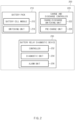
- FIG. 1 is a block diagram illustrating a configuration of a single battery control system.
- a battery control system including a battery pack 1 according to an embodiment of the present disclosure and an upper-level controller 2 included in an upper-level system is schematically illustrated.
- the battery pack 1 may be made of one or more battery cells, and may include a rechargeable battery module 10, a switching unit 14 connected to a (+) terminal or a (-) terminal of the battery module 10 in series to control a charge and discharge current flow of the battery module 10, and a battery management system 20 for controlling and managing by monitoring voltage, current, temperature, or the like of the battery pack 1 to prevent over-charging, over-discharging, or the like.
- the switching unit 14 is a switching element for controlling a current flow for charging or discharging of the battery module 10, and generally uses a relay, but may include a semiconductor switching element.
- a relay for example, at least one relay or one metal-oxide-semiconductor field-effect transistor (MOSFET) may be used.
- MOSFET metal-oxide-semiconductor field-effect transistor
- the battery management system (BMS) 20 may monitor the voltage, current, temperature, or the like, of the battery pack 1 in order to ensure the safety of the battery, and to this end, may directly receive the values or use a sensor 12 to measure the current, voltage, temperature, or the like, of the battery pack.
- the BMS 20 may be an interface for receiving values obtained by measuring the above-mentioned various parameters, and may include a plurality of terminals, a circuit connected to the terminals to process input values, or the like.
- the BMS 20 may control ON/OFF of the switching element 14, for example, a relay or a MOSFET, and may be connected to the battery module 10 to monitor the status of the battery module 10.
- the switching element 14 for example, a relay or a MOSFET
- the upper-level controller 2 may transmit a control signal for the battery module to the BMS 20. Accordingly, the operation of the BMS 20 may be controlled based on the signal applied from the upper-level controller.
- the battery cell described in the present disclosure may be included in a battery pack used in an energy storage system (ESS), a vehicle, or the like. However, it is not limited to the above-mentioned uses.
- the configuration of the battery pack 1 and the configuration of the BMS 20 are known, and thus a more detailed description will be omitted.
- FIG. 2 is a block diagram illustrating a configuration of a battery system including a battery relay diagnostic device according to an embodiment of the present disclosure.
- a battery system 200 includes a plurality of battery packs 210, a charge and discharge controller 220, and a battery relay diagnostic device 230.
- the plurality of battery packs 210 are connected in parallel, and each is connected to the charge and discharge controller 220. Only one charge and discharge controller 220 may be provided regardless of the number of battery packs 210 connected in parallel.
- each of the battery packs 210 may include a battery cell module 212 and a switching unit 214.
- the battery cell module 212 includes a plurality of battery cells connected in series or in parallel.
- the switching unit 214 includes a first switch provided between a (+) terminal of the battery cell module 212 and a load part and a second switch provided between a (-) terminal of the battery cell module and the load part.
- the charge and discharge controller 220 may control charge and discharge of a plurality of battery packs 210 connected in parallel.
- the charge and discharge controller 220 may include a charge/discharge switching unit 222 and a pre-charge unit 224.
- the charge and discharge controller 220 may include only one pre-charge circuit.
- the charge/discharge switching unit 222 may include a positive relay connected to the (+) side of the battery pack 210 connected to others in parallel and a negative relay connected to the (-) side of the battery pack 210 connected to others in parallel.
- the charge/discharge switching unit 222 may control the positive relay and the negative relay to control a current flow applied between the battery pack 210 and a load part.
- the pre-charge unit 224 may include a pre-charge circuit in which a pre-charge resistor and a pre-charge relay are connected in series, and may be connected in parallel to the positive relay of the charge/discharge switching unit 222.
- the pre-charge unit 224 may protect the positive relay by controlling a speed during initial charging of the battery pack 210.
- the battery relay diagnostic device 230 may diagnose the battery pack 210 included in the battery pack 210 about whether it operates normally.
- the battery relay diagnostic device 230 may include a switching controller 232, a diagnostic unit 234, and an alarm unit 236.
- the switching controller 232 may control the current applied to the battery cell module 212 by controlling on/off of the switching unit 214 and the charge/discharge switching unit 222 of the battery pack 210. That is, according to the present disclosure, by diagnosing the switching unit 214 of the battery pack 210, the switching controller 232 may control on/off of the first switch provided between the (+) terminal of the battery cell module 212 and the load part and the second switch provided between the (-) terminal of the battery cell module and the load part, thereby controlling the current applied to the battery cell module 212, and the diagnostic unit 234 may diagnose the first switch and the second switch about whether they operate normally.
- the diagnostic unit 234 performs diagnosis on the first switch and the second switch based on the on/off states of the first switch and the second switch.
- the diagnostic unit 234 performs diagnosis on the first switch and the second switch in an order determined in consideration of interference between the plurality of battery packs 210 connected in parallel, as will be described later.
- the diagnostic unit 234 may perform diagnosis by simultaneously measuring a voltage across the first switch for the plurality of battery packs 210 when both the first switch and the second switch are in an off state, and may perform diagnosis by sequentially measuring a voltage across a terminal of the first switch close to a (+) side of the battery cell module 212 and a terminal of the second switch close to the load part for each of the plurality of battery packs 210.
- the diagnostic unit 234 may perform diagnosis by simultaneously measuring the voltage across the terminal of the first switch close to the (+) side of the battery cell module 212 and the terminal of the second switch close to the load part for the plurality of battery packs 210 when the first switch is in the off state and the second switch is in the on state. In addition, the diagnostic unit 234 may perform diagnosis by sequentially measuring the voltage across the first switch for each of the plurality of battery packs when both the first switch and the second switch are in the on state.
- the alarm unit 236 may generate a warning notification when it is determined that an abnormality occurs in at least one of the first switch and the second switch of the plurality of battery packs 210 by the diagnostic unit 234.
- the battery relay diagnostic device of the present disclosure it is possible to reduce cost and simplify control logic by minimizing the configuration of the pre-charge circuit of battery packs connected in parallel, and to prevent misdiagnosis by performing diagnosis depending on a state of each relay in consideration of the effect of interference from other battery packs connected in parallel.
- FIG. 3a is a diagram illustrating a relay configuration of a battery system in the related art
- FIG. 3b is a diagram illustrating a relay control method for the battery system in the related art.
- the battery system in the related art generally includes a single pack structure and eliminates the pre-charge circuit to reduce costs. Therefore, as illustrated in FIG. 3b , the battery management system (BMS) performs diagnosis on relays by measuring the voltages at each of points A, B, and C after waking up, regardless of the on/off state of each relay.
- BMS battery management system
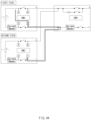
- FIG. 4a is a diagram illustrating a relay configuration of a battery system according to an embodiment of the present disclosure and an interference when relays are off
- FIG. 4b is a diagram illustrating a relay control method for the battery system when the first switch and the second switch are off.
- interference may occur between battery packs connected in parallel, and diagnosis is performed by classifying each battery pack according to the on/off state of the relay.
- the battery pack voltage is applied to points A of a first pack and a second pack of FIG. 4a and a B voltage is OV, which does not affect both battery packs, and thus the measurement of the B voltage may be simultaneously performed for a plurality of battery packs.
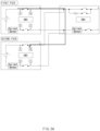
- FIG. 5a is a diagram illustrating a relay configuration of a battery system according to an embodiment of the present disclosure and an interference when relays are on
- FIG. 5b is a diagram illustrating a relay control method for the battery system when the first switch and the second switch are on.
- a C voltage and a D voltage of a first pack and a second pack of FIG. 5a are ground voltages and OV is applied, which does not affect the battery packs, and thus the measurement of the C voltage may be simultaneously performed for a plurality of battery packs.
- the battery relay diagnostic device As described above, with the battery relay diagnostic device according to an embodiment of the present disclosure, it is possible to solve the problem of misdiagnosis by the influence between battery packs by performing diagnosis simultaneously or sequentially in consideration of interference by the on/off states of the relays of each battery pack.
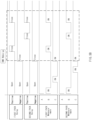
- FIG. 6 is a flowchart illustrating a battery relay diagnostic method according to an embodiment of the present disclosure.
- a battery relay diagnostic method is a diagnostic method for a battery system including a charge and discharge controller connected between a plurality of battery packs connected in parallel and a load part and controlling charge and discharge of battery cell modules included in the battery packs, and the battery packs including the battery cell module including a plurality of battery cells and a switching unit including a first switch provided between a positive (+) terminal of the battery cell module and the load part and a second switch provided between a negative (-) terminal of the battery cell module and the load part.
- the charge and discharge controller may include only one pre-charge circuit.
- the battery relay diagnostic method may be a diagnostic method of performing diagnosis based on the on/off state of relays included in the battery pack (e.g., whether or not there is interference between the battery packs).
- a voltage across the first switch are simultaneously measured for the plurality of battery packs when both the first switch and the second switch are open and are in the off state (S610).
- the battery relay diagnostic method may include generating a warning notification when the diagnostic unit determines that an abnormality occurs in at least one of the first switch and the second switch in the plurality of battery packs.
- the battery relay diagnostic method of the present disclosure it is possible to reduce cost and simplify control logic by minimizing the configuration of the pre-charge circuit of battery packs connected in parallel, and to prevent misdiagnosis by performing diagnosis according to a state of each relay in consideration of the effect of interference from other battery packs connected in parallel.
- FIG. 7 is a diagram illustrating a hardware configuration of a battery relay diagnostic device according to an embodiment of the present disclosure.
- a battery relay diagnostic device 700 may include a microcontroller (MCU) 710 controlling various processes and configurations, a memory 720 in which operating system programs and various programs (e.g., a battery relay diagnostic algorithm program capable of diagnosing the state of the first switch and the second switch, and a battery switching control program capable of controlling a switch in the battery pack) are recorded, an input/output interface 730 for providing an input interface and an output interface through which data of the battery cell module and/or the switching element, such as voltage, current, and temperature, can flow, and a communication interface 740 capable of communicating with the outside through a wired or wireless communication network.
- the computer program according to the present disclosure may be recorded in the memory 720 and processed by the microcontroller 710, so that it may be implemented as a module that performs each functional block illustrated in FIG. 2 .
- the present disclosure has been described as a structure without the pre-charge circuit in the battery pack; however, the principle applied to the present disclosure is to be applied in the same way even for a battery with a pre-charge.
Landscapes
- Engineering & Computer Science (AREA)
- General Chemical & Material Sciences (AREA)
- Chemical & Material Sciences (AREA)
- Chemical Kinetics & Catalysis (AREA)
- Electrochemistry (AREA)
- Power Engineering (AREA)
- Manufacturing & Machinery (AREA)
- Physics & Mathematics (AREA)
- General Physics & Mathematics (AREA)
- Microelectronics & Electronic Packaging (AREA)
- Charge And Discharge Circuits For Batteries Or The Like (AREA)
- Secondary Cells (AREA)
- Protection Of Static Devices (AREA)
Claims (11)
- Batteriesystem (200), umfassend:eine Vielzahl von parallel geschalteten Batteriepacks (210), wobei ein Batteriepack der Batteriepacks (210) ein Batteriezellenmodul (212) einschließt, einschließlich einer Vielzahl von Batteriezellen und eine Schalteinheit (214), einschließlich eines ersten Schalters, der zwischen einem positiven Anschluss des Batteriezellenmoduls (212) und einem Lastteil bereitgestellt ist, und eines zweiten Schalters, der zwischen einem negativen Anschluss des Batteriezellenmoduls (212) und dem Lastteil bereitgestellt ist;eine Lade- und Entladesteuereinheit (220), die zwischen der Vielzahl von Batteriepacks (210) und den Lastteil geschaltet ist, wobei die Lade- und Entladesteuereinheit (220) so konfiguriert ist, dass sie das Laden und Entladen der Vielzahl von Batteriepacks (210) steuert; undeine Batterierelaisdiagnosevorrichtung (230) zum Diagnostizieren des Batteriesystems (200), wobei die Batterierelaisdiagnosevorrichtung (230) Folgendes umfasst:eine Schaltsteuereinheit (232), die so konfiguriert ist, dass sie einen an das Batteriezellenmodul (212) angelegten Strom durch Steuern des Ein-/Ausschaltens der Schalteinheit (214) steuert; undeine Diagnoseeinheit (234), die so konfiguriert ist, dass sie eine Diagnose des ersten Schalters und des zweiten Schalters auf der Grundlage eines Ein/Aus-Zustands des ersten Schalters und des zweiten Schalters durchführt,wobei die Diagnoseeinheit (234) so konfiguriert ist, dass sie die Diagnose gleichzeitig oder aufeinanderfolgend an dem ersten Schalter und an dem zweiten Schalter in einer Reihenfolge durchführt, die unter Berücksichtigung der Interferenz zwischen der Vielzahl von Batteriepacks (210) bestimmt wird.
- System nach Anspruch 1, wobei die Diagnoseeinheit (234) so konfiguriert ist, dass sie eine Diagnose durch gleichzeitiges Messen einer Spannung über dem ersten Schalter für die Vielzahl von Batteriepacks (210) durchführt, wenn sich sowohl der erste Schalter als auch der zweite Schalter in einem Aus-Zustand befinden, und dass sie eine Diagnose durch aufeinanderfolgendes Messen einer Spannung über einem Anschluss des ersten Schalters in der Nähe einer positiven Seite des Batteriezellenmoduls (212) und einem Anschluss des zweiten Schalters in der Nähe des Lastteils für jeden der Vielzahl von Batteriepacks (210) durchführt.
- System nach Anspruch 2, wobei die Diagnoseeinheit (234) so konfiguriert ist, dass sie eine Diagnose durch gleichzeitiges Messen der Spannung über dem Anschluss des ersten Schalters in der Nähe der positiven Seite des Batteriezellenmoduls (212) und dem Anschluss des zweiten Schalters in der Nähe des Lastteils für die Vielzahl von Batteriepacks (210) durchführt, wenn sich der erste Schalter in dem Aus-Zustand befindet und sich der zweite Schalter in einem Ein-Zustand befindet.
- System nach Anspruch 3, wobei die Diagnoseeinheit (234) so konfiguriert ist, dass sie eine Diagnose durch aufeinanderfolgendes Messen der Spannung über dem ersten Schalter für jeden der Vielzahl von Batteriepacks (210) durchführt, wenn sich sowohl der erste Schalter als auch der zweite Schalter in dem Ein-Zustand befinden.
- System nach Anspruch 1, wobei die Batterierelaisdiagnosevorrichtung (230) weiter eine Alarmeinheit (236) umfasst, die so konfiguriert ist, dass sie eine Warnmeldung erzeugt, wenn die Diagnoseeinheit (234) bestimmt, dass eine Anomalie in mindestens einem von dem ersten Schalter und dem zweiten Schalter in der Vielzahl von Batteriepacks (210) auftritt.
- System nach Anspruch 1, wobei Anschlüsse der ersten Schalter in der Vielzahl von Batteriepacks (210) in der Nähe des Lastteils miteinander verbunden sind, und Anschlüsse der zweiten Schalter in der Vielzahl von Batteriepacks (210) in der Nähe des Lastteils miteinander verbunden sind.
- System nach Anspruch 1, wobei die Lade- und Entladesteuereinheit (220) nur eine Vorladeschaltung (224) einschließt.
- Batterierelaisdiagnoseverfahren zum Diagnostizieren eines Batteriesystems (200) einschließlich einer Vielzahl von parallel geschalteten Batteriepacks (210) und einer Lade- und Entladesteuereinheit (220), die zwischen den parallel geschalteten Batteriepacks (210) und einem Lastteil geschaltet ist, wobei die Lade- und Entladesteuereinheit (220) das Laden und Entladen der Batteriepacks (210) steuert, wobei ein Batteriepack (210) der Batteriepacks ein Batteriezellenmodul (212) einschließt, einschließlich einer Vielzahl von Batteriezellen und eine Schalteinheit (214) einschließlich eines ersten Schalters, der zwischen einem positiven Anschluss des Batteriezellenmoduls (212) und dem Lastteil bereitgestellt ist, und eines zweiten Schalters, der zwischen einem negativen Anschluss des Batteriezellenmoduls (212) und dem Lastteil bereitgestellt ist, wobei das Diagnoseverfahren Folgendes umfasst:Durchführen einer Diagnose an dem ersten Schalter und an dem zweiten Schalter auf der Grundlage eines Ein/Aus-Zustands des ersten Schalters und des zweiten Schalters,wobei das Durchführen der Diagnose an dem ersten Schalter und an dem zweiten Schalter das gleichzeitige oder aufeinanderfolgende Durchführen der Diagnose an dem ersten Schalter und dem zweiten Schalter in einer Reihenfolge einschließt, die unter Berücksichtigung der Interferenz zwischen der Vielzahl von Batteriepacks (210) bestimmt wird.
- Batterierelaisdiagnoseverfahren nach Anspruch 8, wobei die Durchführung der Diagnose an dem ersten Schalter und an dem zweiten Schalter Folgendes einschließt:gleichzeitiges Messen einer Spannung über dem ersten Schalter für die Vielzahl von Batteriepacks (210), wenn sich sowohl der erste Schalter als auch der zweite Schalter in einem Aus-Zustand befinden; undaufeinanderfolgendes Messen einer Spannung über einem Anschluss des ersten Schalters in der Nähe einer positiven Seite des Batteriezellenmoduls (212) und einem Anschluss des zweiten Schalters in der Nähe des Lastteils für jeden der Vielzahl von Batteriepacks (210).
- Batterierelaisdiagnoseverfahren nach Anspruch 9, wobei das Durchführen der Diagnose an dem ersten Schalter und an dem zweiten Schalter das gleichzeitige Messen der Spannung über dem Anschluss des ersten Schalters in der Nähe der positiven Seite des Batteriezellenmoduls (212) und dem Anschluss des zweiten Schalters in der Nähe des Lastteils für die Vielzahl von Batteriepacks (210) einschließt, wenn sich der erste Schalter in dem Aus-Zustand befindet und sich der zweite Schalter in einem Ein-Zustand befindet.
- Batterierelaisdiagnoseverfahren nach Anspruch 10, wobei das Durchführen der Diagnose an dem ersten Schalter und an dem zweiten Schalter ein aufeinanderfolgendes Messen der Spannung über dem ersten Schalter für jeden der Vielzahl von Batteriepacks (210) einschließt, wenn sich sowohl der erste Schalter als auch der zweite Schalter in dem Ein-Zustand befinden.
Applications Claiming Priority (2)
| Application Number | Priority Date | Filing Date | Title |
|---|---|---|---|
| KR1020190172452A KR102785104B1 (ko) | 2019-12-20 | 2019-12-20 | 병렬 배터리 릴레이 진단 장치 및 방법 |
| PCT/KR2020/017934 WO2021125678A1 (ko) | 2019-12-20 | 2020-12-09 | 병렬 배터리 릴레이 진단 장치 및 방법 |
Publications (3)
| Publication Number | Publication Date |
|---|---|
| EP3974850A1 EP3974850A1 (de) | 2022-03-30 |
| EP3974850A4 EP3974850A4 (de) | 2022-12-28 |
| EP3974850B1 true EP3974850B1 (de) | 2025-01-29 |
Family
ID=76477760
Family Applications (1)
| Application Number | Title | Priority Date | Filing Date |
|---|---|---|---|
| EP20902610.3A Active EP3974850B1 (de) | 2019-12-20 | 2020-12-09 | Vorrichtung und verfahren zur diagnose eines parallelbatterierelais |
Country Status (8)
| Country | Link |
|---|---|
| US (1) | US11946974B2 (de) |
| EP (1) | EP3974850B1 (de) |
| JP (1) | JP7315142B2 (de) |
| KR (1) | KR102785104B1 (de) |
| CN (1) | CN114097159B (de) |
| ES (1) | ES3013691T3 (de) |
| HU (1) | HUE070153T2 (de) |
| WO (1) | WO2021125678A1 (de) |
Families Citing this family (8)
| Publication number | Priority date | Publication date | Assignee | Title |
|---|---|---|---|---|
| KR102640845B1 (ko) * | 2021-01-19 | 2024-02-28 | 삼성에스디아이 주식회사 | 배터리 팩 및 배터리 팩의 제어 방법 |
| KR20230090024A (ko) | 2021-12-14 | 2023-06-21 | 주식회사 엘지에너지솔루션 | 릴레이 진단 장치 및 릴레이 진단 방법 |
| KR20230106344A (ko) * | 2022-01-06 | 2023-07-13 | 주식회사 엘지에너지솔루션 | 융착 진단 방법 및 이를 이용한 배터리 시스템 |
| KR20230123838A (ko) * | 2022-02-17 | 2023-08-24 | 주식회사 엘지에너지솔루션 | 배터리 관리 장치 및 그것의 동작 방법 |
| CN114976506A (zh) * | 2022-05-19 | 2022-08-30 | 盐城国投中科新能源科技有限公司 | 一种启动锂电池系统并联装置及其使用方法 |
| KR20240074971A (ko) | 2022-11-15 | 2024-05-29 | 현대자동차주식회사 | 배터리 팩 진단 제어 장치, 그를 포함하는 배터리 시스템 및 그 방법 |
| US20240329138A1 (en) * | 2023-03-27 | 2024-10-03 | Samsung Sdi Co., Ltd. | Battery pack and method of operating the same |
| CN116819303B (zh) * | 2023-06-28 | 2025-08-22 | 广东汇天航空航天科技有限公司 | 高压电池包的开关检测电路、检测方法和电动交通工具 |
Family Cites Families (33)
| Publication number | Priority date | Publication date | Assignee | Title |
|---|---|---|---|---|
| JP3945630B2 (ja) | 2002-01-10 | 2007-07-18 | パナソニック・イーブイ・エナジー株式会社 | 電池電源装置のリレー接点溶着検査方法 |
| JP4934628B2 (ja) | 2008-04-09 | 2012-05-16 | 日立オートモティブシステムズ株式会社 | 二重系電源装置 |
| JP5508180B2 (ja) | 2010-08-02 | 2014-05-28 | 日立ビークルエナジー株式会社 | 蓄電装置、蓄電装置の充放電方法、蓄電装置の運転方法および車両 |
| KR101367875B1 (ko) | 2011-03-21 | 2014-02-26 | 주식회사 엘지화학 | 배터리 팩 연결 제어 장치 및 방법 |
| KR101255248B1 (ko) | 2011-07-04 | 2013-04-16 | 로베르트 보쉬 게엠베하 | 배터리 관리 시스템 및 이의 제어 방법 |
| KR101394341B1 (ko) * | 2011-08-19 | 2014-05-14 | 한국과학기술원 | 전기 차량의 전력 공급 신뢰성을 위한 배터리팩 이중 병렬 장치 및 제어 방법 |
| KR101460845B1 (ko) | 2011-12-21 | 2014-11-11 | 주식회사 엘지화학 | 배터리 팩 전압 평형 방법 및 장치 |
| JP2013206643A (ja) * | 2012-03-28 | 2013-10-07 | Hitachi Ltd | 電池システムのリレー溶着検知装置、及びこれを用いた電池システム |
| KR101926195B1 (ko) * | 2012-07-09 | 2019-02-26 | 에스케이이노베이션 주식회사 | 병렬 팩 배터리 시스템의 릴레이 융착 관리 장치 및 그 방법 |
| JP5768780B2 (ja) | 2012-08-07 | 2015-08-26 | 株式会社豊田自動織機 | 蓄電装置モジュール用制御装置 |
| JP2014093806A (ja) | 2012-11-01 | 2014-05-19 | Suzuki Motor Corp | 車両用電源装置 |
| KR101602434B1 (ko) | 2012-11-09 | 2016-03-21 | 주식회사 엘지화학 | 충전시 발생하는 셀 밸런싱 스위치의 오진단 방지 장치 및 오진단 방지 방법 |
| CN104885326B (zh) * | 2012-12-28 | 2017-06-13 | 日立麦克赛尔株式会社 | 组合电池系统、蓄电池系统以及组合电池系统的监视控制方法 |
| JP2014143796A (ja) | 2013-01-22 | 2014-08-07 | Toshiba Corp | 電源装置 |
| JP5751282B2 (ja) | 2013-05-29 | 2015-07-22 | 株式会社デンソー | 制御装置 |
| JP6185337B2 (ja) * | 2013-08-26 | 2017-08-23 | 株式会社トランストロン | リレー回路の診断装置及び診断方法 |
| WO2015068186A1 (ja) * | 2013-11-06 | 2015-05-14 | 川崎重工業株式会社 | 乗物およびそれに用いる電源ユニット |
| KR20150091890A (ko) | 2014-02-04 | 2015-08-12 | 삼성에스디아이 주식회사 | 배터리 트레이, 배터리 랙, 에너지 저장 시스템, 및 배터리 트레이의 동작 방법 |
| KR102210282B1 (ko) | 2014-05-30 | 2021-02-01 | 삼성전자주식회사 | 릴레이 상태 검출 방법 및 장치 |
| KR101498458B1 (ko) | 2014-10-31 | 2015-03-12 | 건아정보기술 주식회사 | 복수의 레이저빔을 이용하여 객체 및 속도 감지를 병행하는 차량용 방범 촬영시스템 |
| JP6589368B2 (ja) * | 2015-05-20 | 2019-10-16 | 日産自動車株式会社 | 電源装置、及び、電源装置の異常を診断する診断方法 |
| CN104878295A (zh) | 2015-06-25 | 2015-09-02 | 潘应生 | 一种铜铁合金及表面处理工艺 |
| JP6569623B2 (ja) | 2016-08-09 | 2019-09-04 | トヨタ自動車株式会社 | 蓄電システム |
| KR102044598B1 (ko) * | 2016-09-09 | 2019-11-13 | 주식회사 엘지화학 | 배터리 팩 고장 검출 장치 및 방법 |
| JP6618443B2 (ja) * | 2016-09-21 | 2019-12-11 | 株式会社エンビジョンAescジャパン | 電源システムの充電停止方法 |
| KR102360014B1 (ko) * | 2017-02-01 | 2022-02-07 | 삼성에스디아이 주식회사 | 배터리 관리 시스템 및 배터리 관리 시스템의 충전 제어 방법 |
| JP6831281B2 (ja) | 2017-03-27 | 2021-02-17 | 株式会社デンソーテン | 電池監視システムおよび電池監視装置 |
| KR102204983B1 (ko) * | 2017-09-25 | 2021-01-18 | 주식회사 엘지화학 | 배터리 관리 장치와 이를 포함하는 배터리 팩 및 자동차 |
| DE102017223229A1 (de) * | 2017-12-19 | 2019-06-19 | Volkswagen Aktiengesellschaft | Elektrisches System und Verfahren zur Diagnose der Funktionsfähigkeit von Leistungsrelais in einem elektrischen System |
| JP6901989B2 (ja) | 2018-03-19 | 2021-07-14 | 株式会社デンソーテン | 電池監視装置、電池監視システム、および電池監視方法 |
| JP6963358B2 (ja) * | 2018-03-26 | 2021-11-10 | 株式会社エンビジョンAescジャパン | 電源装置 |
| EP3664251B1 (de) * | 2018-12-07 | 2021-03-03 | Yazaki Corporation | Stromversorgungssystem |
| JP6733783B2 (ja) * | 2019-06-26 | 2020-08-05 | 日産自動車株式会社 | 電源装置、及び、電源装置の異常を診断する診断方法 |
-
2019
- 2019-12-20 KR KR1020190172452A patent/KR102785104B1/ko active Active
-
2020
- 2020-12-09 ES ES20902610T patent/ES3013691T3/es active Active
- 2020-12-09 EP EP20902610.3A patent/EP3974850B1/de active Active
- 2020-12-09 US US17/626,678 patent/US11946974B2/en active Active
- 2020-12-09 WO PCT/KR2020/017934 patent/WO2021125678A1/ko not_active Ceased
- 2020-12-09 CN CN202080048462.4A patent/CN114097159B/zh active Active
- 2020-12-09 HU HUE20902610A patent/HUE070153T2/hu unknown
- 2020-12-09 JP JP2021572012A patent/JP7315142B2/ja active Active
Also Published As
| Publication number | Publication date |
|---|---|
| US11946974B2 (en) | 2024-04-02 |
| EP3974850A4 (de) | 2022-12-28 |
| WO2021125678A1 (ko) | 2021-06-24 |
| US20220260637A1 (en) | 2022-08-18 |
| CN114097159B (zh) | 2024-07-19 |
| KR102785104B1 (ko) | 2025-03-21 |
| JP7315142B2 (ja) | 2023-07-26 |
| EP3974850A1 (de) | 2022-03-30 |
| JP2022535114A (ja) | 2022-08-04 |
| CN114097159A (zh) | 2022-02-25 |
| KR20210080070A (ko) | 2021-06-30 |
| HUE070153T2 (hu) | 2025-05-28 |
| ES3013691T3 (en) | 2025-04-14 |
Similar Documents
| Publication | Publication Date | Title |
|---|---|---|
| EP3974850B1 (de) | Vorrichtung und verfahren zur diagnose eines parallelbatterierelais | |
| EP3982140B1 (de) | Vorrichtung zur batterieverwaltung und verfahren zur batterieverwaltung | |
| EP3561940B1 (de) | Master-batterieverwaltungseinheit und batteriepack damit | |
| EP3958006B1 (de) | Batteriediagnosevorrichtung und -verfahren | |
| US12218530B2 (en) | System and method for managing battery | |
| EP2523248B1 (de) | Batterieüberwachungsvorrichtung und -verfahren | |
| JP5819443B2 (ja) | 電池制御装置、電池システム | |
| KR102729158B1 (ko) | 릴레이 진단 장치, 릴레이 진단 방법, 배터리 시스템 및 전기 차량 | |
| KR102758018B1 (ko) | 배터리 관리 시스템, 배터리 팩, 에너지 저장 시스템 및 배터리 관리 방법 | |
| JP2022537796A (ja) | バッテリー診断装置及び方法 | |
| JP7127248B2 (ja) | バッテリー管理システム、バッテリー管理方法、バッテリーパック及び電気車両 | |
| US20240066993A1 (en) | Battery Diagnosis Device, Battery Management System, Battery Pack, Electric Vehicle And Battery Diagnosis Method | |
| KR20180026947A (ko) | 전력 공급 회로 및 이를 포함하는 배터리 팩 | |
| KR20200030393A (ko) | 스위치 진단 장치 및 방법 | |
| EP3290936A1 (de) | Parallele überwachungsvorrichtung für batteriepackzustand | |
| JP2001352688A (ja) | 組電池の電圧調整装置及び組電池の電圧調整方法 | |
| US11979050B2 (en) | Battery charge/discharge control device and battery management device | |
| KR102761622B1 (ko) | 배터리 전류 측정 장치 및 방법과, 배터리 팩 | |
| JP7601528B2 (ja) | 電池制御システムおよび方法 | |
| EP4303600A1 (de) | Spannungsbestimmungsschaltung | |
| US20240421610A1 (en) | Battery Control System and Method for Managing Battery State | |
| KR20250097496A (ko) | 배터리 관리 장치 및 그것의 동작 방법 | |
| KR20240045915A (ko) | 배터리 셀 진단 장치 및 그것의 동작 방법 | |
| KR20250017586A (ko) | 배터리 진단 장치 및 방법 | |
| KR20250131917A (ko) | 배터리 팩 및 그것의 동작 방법 |
Legal Events
| Date | Code | Title | Description |
|---|---|---|---|
| STAA | Information on the status of an ep patent application or granted ep patent |
Free format text: STATUS: THE INTERNATIONAL PUBLICATION HAS BEEN MADE |
|
| PUAI | Public reference made under article 153(3) epc to a published international application that has entered the european phase |
Free format text: ORIGINAL CODE: 0009012 |
|
| STAA | Information on the status of an ep patent application or granted ep patent |
Free format text: STATUS: REQUEST FOR EXAMINATION WAS MADE |
|
| 17P | Request for examination filed |
Effective date: 20211220 |
|
| AK | Designated contracting states |
Kind code of ref document: A1 Designated state(s): AL AT BE BG CH CY CZ DE DK EE ES FI FR GB GR HR HU IE IS IT LI LT LU LV MC MK MT NL NO PL PT RO RS SE SI SK SM TR |
|
| A4 | Supplementary search report drawn up and despatched |
Effective date: 20221128 |
|
| RIC1 | Information provided on ipc code assigned before grant |
Ipc: H01M 10/42 20060101ALI20221122BHEP Ipc: H01M 10/48 20060101ALI20221122BHEP Ipc: G01R 31/327 20060101AFI20221122BHEP |
|
| DAV | Request for validation of the european patent (deleted) | ||
| DAX | Request for extension of the european patent (deleted) | ||
| GRAP | Despatch of communication of intention to grant a patent |
Free format text: ORIGINAL CODE: EPIDOSNIGR1 |
|
| STAA | Information on the status of an ep patent application or granted ep patent |
Free format text: STATUS: GRANT OF PATENT IS INTENDED |
|
| INTG | Intention to grant announced |
Effective date: 20240923 |
|
| GRAS | Grant fee paid |
Free format text: ORIGINAL CODE: EPIDOSNIGR3 |
|
| P01 | Opt-out of the competence of the unified patent court (upc) registered |
Free format text: CASE NUMBER: APP_60668/2024 Effective date: 20241111 |
|
| GRAA | (expected) grant |
Free format text: ORIGINAL CODE: 0009210 |
|
| STAA | Information on the status of an ep patent application or granted ep patent |
Free format text: STATUS: THE PATENT HAS BEEN GRANTED |
|
| AK | Designated contracting states |
Kind code of ref document: B1 Designated state(s): AL AT BE BG CH CY CZ DE DK EE ES FI FR GB GR HR HU IE IS IT LI LT LU LV MC MK MT NL NO PL PT RO RS SE SI SK SM TR |
|
| REG | Reference to a national code |
Ref country code: GB Ref legal event code: FG4D |
|
| REG | Reference to a national code |
Ref country code: CH Ref legal event code: EP |
|
| REG | Reference to a national code |
Ref country code: DE Ref legal event code: R096 Ref document number: 602020045661 Country of ref document: DE |
|
| REG | Reference to a national code |
Ref country code: IE Ref legal event code: FG4D |
|
| REG | Reference to a national code |
Ref country code: ES Ref legal event code: FG2A Ref document number: 3013691 Country of ref document: ES Kind code of ref document: T3 Effective date: 20250414 |
|
| REG | Reference to a national code |
Ref country code: HU Ref legal event code: AG4A Ref document number: E070153 Country of ref document: HU |
|
| REG | Reference to a national code |
Ref country code: NL Ref legal event code: MP Effective date: 20250129 |
|
| PG25 | Lapsed in a contracting state [announced via postgrant information from national office to epo] |
Ref country code: NL Free format text: LAPSE BECAUSE OF FAILURE TO SUBMIT A TRANSLATION OF THE DESCRIPTION OR TO PAY THE FEE WITHIN THE PRESCRIBED TIME-LIMIT Effective date: 20250129 |
|
| PG25 | Lapsed in a contracting state [announced via postgrant information from national office to epo] |
Ref country code: RS Free format text: LAPSE BECAUSE OF FAILURE TO SUBMIT A TRANSLATION OF THE DESCRIPTION OR TO PAY THE FEE WITHIN THE PRESCRIBED TIME-LIMIT Effective date: 20250429 |
|
| PG25 | Lapsed in a contracting state [announced via postgrant information from national office to epo] |
Ref country code: FI Free format text: LAPSE BECAUSE OF FAILURE TO SUBMIT A TRANSLATION OF THE DESCRIPTION OR TO PAY THE FEE WITHIN THE PRESCRIBED TIME-LIMIT Effective date: 20250129 |
|
| PG25 | Lapsed in a contracting state [announced via postgrant information from national office to epo] |
Ref country code: PL Free format text: LAPSE BECAUSE OF FAILURE TO SUBMIT A TRANSLATION OF THE DESCRIPTION OR TO PAY THE FEE WITHIN THE PRESCRIBED TIME-LIMIT Effective date: 20250129 |
|
| REG | Reference to a national code |
Ref country code: LT Ref legal event code: MG9D |
|
| PG25 | Lapsed in a contracting state [announced via postgrant information from national office to epo] |
Ref country code: IS Free format text: LAPSE BECAUSE OF FAILURE TO SUBMIT A TRANSLATION OF THE DESCRIPTION OR TO PAY THE FEE WITHIN THE PRESCRIBED TIME-LIMIT Effective date: 20250529 Ref country code: NO Free format text: LAPSE BECAUSE OF FAILURE TO SUBMIT A TRANSLATION OF THE DESCRIPTION OR TO PAY THE FEE WITHIN THE PRESCRIBED TIME-LIMIT Effective date: 20250429 |
|
| REG | Reference to a national code |
Ref country code: AT Ref legal event code: MK05 Ref document number: 1763958 Country of ref document: AT Kind code of ref document: T Effective date: 20250129 |
|
| PG25 | Lapsed in a contracting state [announced via postgrant information from national office to epo] |
Ref country code: HR Free format text: LAPSE BECAUSE OF FAILURE TO SUBMIT A TRANSLATION OF THE DESCRIPTION OR TO PAY THE FEE WITHIN THE PRESCRIBED TIME-LIMIT Effective date: 20250129 |
|
| PG25 | Lapsed in a contracting state [announced via postgrant information from national office to epo] |
Ref country code: LV Free format text: LAPSE BECAUSE OF FAILURE TO SUBMIT A TRANSLATION OF THE DESCRIPTION OR TO PAY THE FEE WITHIN THE PRESCRIBED TIME-LIMIT Effective date: 20250129 Ref country code: PT Free format text: LAPSE BECAUSE OF FAILURE TO SUBMIT A TRANSLATION OF THE DESCRIPTION OR TO PAY THE FEE WITHIN THE PRESCRIBED TIME-LIMIT Effective date: 20250529 |
|
| PG25 | Lapsed in a contracting state [announced via postgrant information from national office to epo] |
Ref country code: GR Free format text: LAPSE BECAUSE OF FAILURE TO SUBMIT A TRANSLATION OF THE DESCRIPTION OR TO PAY THE FEE WITHIN THE PRESCRIBED TIME-LIMIT Effective date: 20250430 Ref country code: BG Free format text: LAPSE BECAUSE OF FAILURE TO SUBMIT A TRANSLATION OF THE DESCRIPTION OR TO PAY THE FEE WITHIN THE PRESCRIBED TIME-LIMIT Effective date: 20250129 |
|
| PG25 | Lapsed in a contracting state [announced via postgrant information from national office to epo] |
Ref country code: AT Free format text: LAPSE BECAUSE OF FAILURE TO SUBMIT A TRANSLATION OF THE DESCRIPTION OR TO PAY THE FEE WITHIN THE PRESCRIBED TIME-LIMIT Effective date: 20250129 |
|
| PG25 | Lapsed in a contracting state [announced via postgrant information from national office to epo] |
Ref country code: SE Free format text: LAPSE BECAUSE OF FAILURE TO SUBMIT A TRANSLATION OF THE DESCRIPTION OR TO PAY THE FEE WITHIN THE PRESCRIBED TIME-LIMIT Effective date: 20250129 |
|
| PG25 | Lapsed in a contracting state [announced via postgrant information from national office to epo] |
Ref country code: SM Free format text: LAPSE BECAUSE OF FAILURE TO SUBMIT A TRANSLATION OF THE DESCRIPTION OR TO PAY THE FEE WITHIN THE PRESCRIBED TIME-LIMIT Effective date: 20250129 |
|
| PG25 | Lapsed in a contracting state [announced via postgrant information from national office to epo] |
Ref country code: DK Free format text: LAPSE BECAUSE OF FAILURE TO SUBMIT A TRANSLATION OF THE DESCRIPTION OR TO PAY THE FEE WITHIN THE PRESCRIBED TIME-LIMIT Effective date: 20250129 |
|
| PG25 | Lapsed in a contracting state [announced via postgrant information from national office to epo] |
Ref country code: IT Free format text: LAPSE BECAUSE OF FAILURE TO SUBMIT A TRANSLATION OF THE DESCRIPTION OR TO PAY THE FEE WITHIN THE PRESCRIBED TIME-LIMIT Effective date: 20250129 |
|
| PG25 | Lapsed in a contracting state [announced via postgrant information from national office to epo] |
Ref country code: CZ Free format text: LAPSE BECAUSE OF FAILURE TO SUBMIT A TRANSLATION OF THE DESCRIPTION OR TO PAY THE FEE WITHIN THE PRESCRIBED TIME-LIMIT Effective date: 20250129 Ref country code: EE Free format text: LAPSE BECAUSE OF FAILURE TO SUBMIT A TRANSLATION OF THE DESCRIPTION OR TO PAY THE FEE WITHIN THE PRESCRIBED TIME-LIMIT Effective date: 20250129 |
|
| PG25 | Lapsed in a contracting state [announced via postgrant information from national office to epo] |
Ref country code: RO Free format text: LAPSE BECAUSE OF FAILURE TO SUBMIT A TRANSLATION OF THE DESCRIPTION OR TO PAY THE FEE WITHIN THE PRESCRIBED TIME-LIMIT Effective date: 20250129 |
|
| PG25 | Lapsed in a contracting state [announced via postgrant information from national office to epo] |
Ref country code: SK Free format text: LAPSE BECAUSE OF FAILURE TO SUBMIT A TRANSLATION OF THE DESCRIPTION OR TO PAY THE FEE WITHIN THE PRESCRIBED TIME-LIMIT Effective date: 20250129 |
|
| REG | Reference to a national code |
Ref country code: DE Ref legal event code: R097 Ref document number: 602020045661 Country of ref document: DE |
|
| PLBE | No opposition filed within time limit |
Free format text: ORIGINAL CODE: 0009261 |
|
| STAA | Information on the status of an ep patent application or granted ep patent |
Free format text: STATUS: NO OPPOSITION FILED WITHIN TIME LIMIT |