EP3972452B1 - Schwenkbeschlag und möbel - Google Patents
Schwenkbeschlag und möbel Download PDFInfo
- Publication number
- EP3972452B1 EP3972452B1 EP20726813.7A EP20726813A EP3972452B1 EP 3972452 B1 EP3972452 B1 EP 3972452B1 EP 20726813 A EP20726813 A EP 20726813A EP 3972452 B1 EP3972452 B1 EP 3972452B1
- Authority
- EP
- European Patent Office
- Prior art keywords
- pivot fitting
- disc
- force
- toothed
- furniture
- Prior art date
- Legal status (The legal status is an assumption and is not a legal conclusion. Google has not performed a legal analysis and makes no representation as to the accuracy of the status listed.)
- Active
Links
Images


Classifications
-
- A—HUMAN NECESSITIES
- A47—FURNITURE; DOMESTIC ARTICLES OR APPLIANCES; COFFEE MILLS; SPICE MILLS; SUCTION CLEANERS IN GENERAL
- A47C—CHAIRS; SOFAS; BEDS
- A47C1/00—Chairs adapted for special purposes
- A47C1/02—Reclining or easy chairs
- A47C1/022—Reclining or easy chairs having independently-adjustable supporting parts
- A47C1/024—Reclining or easy chairs having independently-adjustable supporting parts the parts, being the back-rest, or the back-rest and seat unit, having adjustable and lockable inclination
- A47C1/026—Reclining or easy chairs having independently-adjustable supporting parts the parts, being the back-rest, or the back-rest and seat unit, having adjustable and lockable inclination by means of peg-and-notch or pawl-and-ratchet mechanism
-
- A—HUMAN NECESSITIES
- A47—FURNITURE; DOMESTIC ARTICLES OR APPLIANCES; COFFEE MILLS; SPICE MILLS; SUCTION CLEANERS IN GENERAL
- A47C—CHAIRS; SOFAS; BEDS
- A47C1/00—Chairs adapted for special purposes
- A47C1/02—Reclining or easy chairs
- A47C1/031—Reclining or easy chairs having coupled concurrently adjustable supporting parts
-
- A—HUMAN NECESSITIES
- A47—FURNITURE; DOMESTIC ARTICLES OR APPLIANCES; COFFEE MILLS; SPICE MILLS; SUCTION CLEANERS IN GENERAL
- A47C—CHAIRS; SOFAS; BEDS
- A47C7/00—Parts, details, or accessories of chairs or stools
- A47C7/36—Supports for the head or the back
- A47C7/38—Supports for the head or the back for the head, e.g. detachable
-
- A—HUMAN NECESSITIES
- A47—FURNITURE; DOMESTIC ARTICLES OR APPLIANCES; COFFEE MILLS; SPICE MILLS; SUCTION CLEANERS IN GENERAL
- A47C—CHAIRS; SOFAS; BEDS
- A47C7/00—Parts, details, or accessories of chairs or stools
- A47C7/54—Supports for the arms
- A47C7/541—Supports for the arms of adjustable type
Definitions
- the present invention relates to a swivel fitting, in particular for movable furniture parts on seating or reclining furniture according to the preamble of claim 1 and a piece of furniture.
- a generic swivel fitting is, for example, from DE 10 2017 110 253 A1 known.
- two levers can be fixed relative to one another via a clamping mechanism.
- One of these levers can be attached to a base body or seat part of upholstered furniture, while the second lever serves to fix a pivotably mounted headrest, armrest, footrest or another furniture part pivotably mounted on the base body or seat part of the furniture.
- the pivotable furniture part can be pivoted from an initial position into a predetermined pivoted position and fixed in this pivoted position.
- the swivel fitting is designed in such a way that the furniture part to be adjusted can be adjusted from any swivel position without the two levers first having to be swiveled back into the basic position.
- overload clutches are relatively expensive to manufacture.
- overload clutch has to be re-engaged at the point at which it disengaged, or at least can only be re-engaged in a shifted grid.
- DE102017110253 A1 discloses a swivel fitting according to the preamble of claim 1.
- the object of the present invention is to further develop a swivel fitting of the generic type such that the swivel fitting is also protected against overload in a simple and cost-effective manner.
- a further object of the invention is to provide a piece of furniture with which the functioning of a piece of furniture with movable components is further improved.
- the first object is achieved by a swivel fitting with the features of claim 1.
- the second object is achieved by a piece of furniture with the features of claim 12.
- the swivel fitting according to the invention has at least one first lever, which is mounted around a force shaft serving as the axis of rotation and can be swiveled out of a basic position by a predetermined angle relative to the latter.
- the swivel fitting also has a clamping mechanism with which the first lever can be fixed in different angular positions within the predetermined angle relative to the power shaft.
- This clamping mechanism has a toothed ring disk placed on the power shaft with external teeth formed on the outer edge and a pawl pivotally mounted on the first lever and loaded in the direction of the external teeth, which in a detent position engages with the external teeth of the toothed ring disk.
- the clamping mechanism also has a first control disk, which is rotatably mounted around the power shaft and with which the at least one pawl can be disengaged from the toothing in an adjustment direction after the predetermined angle has been traversed from the basic position, so that when the pawl is disengaged from the toothing by crossing the predetermined angle in a return direction, the first lever can be pivoted back into the basic position relative to the power shaft.
- At least one friction disk arranged on the power shaft in a rotationally fixed and axially secured manner is pushed onto the annular gear disk, the annular gear disk is held frictionally on the at least one friction disc up to a predetermined torque against rotation about the axis of rotation.
- an overload safety device that is easy to assemble and inexpensive in terms of its components is made possible, with which the power shaft is decoupled from the toothed ring disk and thus the power shaft from the first lever in the event of an overload.
- the first lever can be pivoted relative to the power shaft without damaging the clamping mechanism.
- an inner peripheral edge of the toothed ring disk is conically shaped and pushed onto a cone arranged on the power shaft.
- the at least one friction disc is pressed against the annular gear disc on the side of the smaller diameter of the inner peripheral edge of the annular gear disc.
- the cone arranged on the power shaft and the friction disk press the friction disk arranged non-rotatably on the power shaft and the annular gear disk together in such a way that the predetermined torque defining the overload limit must be exceeded for the relative rotation of the friction disk to the annular gear disk.
- the resilient pressure force of the friction disk creates friction on the cone and on the contact surface of the toothed ring disk.
- the predetermined torque can be defined depending on the selected pressure force or coefficient of friction between the contact surface of the toothed ring disk on the friction disk and the predefined cone angle.
- the cone is formed in one piece on the power shaft, which enables extremely simple assembly.
- the cone is mounted on the power shaft.
- the power shaft itself and the cone to be produced as an individual component, for example as a sheet metal element, can be produced very inexpensively.
- the cone is designed as a radially slotted clamping ring.
- the cone angle of the cone is between 15° and 35°, particularly preferably between 20° and 30°.
- a friction disk arranged in a rotationally fixed and axially secured manner is pushed on on both sides of the toothed ring disk.
- a plurality of toothed ring disks are placed on the power shaft, with a friction disk held non-rotatably on the power shaft being arranged between two toothed ring disks.
- two toothed ring disks are used with a friction disk arranged between them.
- the force exerted by the friction disks which are fixed and/or pressed onto the power shaft in a rotationally fixed manner thus creates friction at six contact points (in the case of three toothed ring disks) or four contact points (in the case of two toothed ring disks used), via which the torque provided for the overload protection can be adjusted .
- the wear and the overload torque can be set in a simple manner via the spring force and pressing depth of the friction discs used and the number of toothed ring discs used.
- a tab is formed on the first control disk, which extends perpendicularly to the plane of the first control disk axially to the power shaft outwards into a recess provided for this purpose in a recess of the first lever.
- a recess is formed on an outer edge of the friction disk, in which a switching element is accommodated so that it can pivot about a switching angle in the plane of the friction disk.
- This switching element also serves as an alternative to the combination of the control pin arranged on the first lever and the recess in the first control disk.
- the friction disk accommodating the switching element has a thickness, in the axial direction of the power shaft, which is greater than the thickness of the switching element.
- the at least one friction disk is pressed onto the power shaft with a press fit against the annular gear disk.
- the friction disk is designed as a plate spring.
- a switching contour is formed on an outer edge of the friction disk.
- the predetermined torque up to which the toothed ring disk is frictionally held against rotation about the axis by the at least one friction disk is at least 70 Nm, preferably at least 80 Nm.
- a particular advantage of the arrangement according to the invention is that the swivel fitting enables a maximum adjustment angle of approximately 250°. This is made possible by the arrangement of the control bolts and the stops as well as the internal structure with the toothed ring disc, the control disc and the pawl.
- a second lever is coupled to the power shaft in a rotationally fixed manner.
- the furniture according to the invention is characterized by a swivel fitting as described above.
- the second lever is part of the adjustable furniture part.
- top, bottom, left, right, front, rear, etc. refer exclusively to the exemplary representation and position of the swivel fitting, lever, toothed ring disk, pawl, power shaft, cone, selected in the respective figures. the friction disk and the like. These terms are not to be understood as limiting, i.e. these references can change due to different working positions or the mirror-symmetrical design or the like.
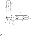
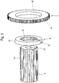
- figure 1 is denoted by the reference numeral 1 as a whole an embodiment of a swivel fitting according to the invention.
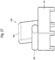
- Such a swivel fitting 1 is used in particular to enable a swiveling movement of movable furniture parts on furniture, such as an armrest 103 or a backrest 102, headrest or footrest of a piece of furniture 100 designed as seating or lying furniture, as is exemplified in figures 27 and 28 is shown.
- the swivel fitting 1 has a first lever 2 and a second lever 3 in the embodiment variant shown here.
- the two levers 2, 3 are mounted pivotably relative to one another about a pivot axis D from a basic position by a predetermined angle in an adjustment direction V and a return direction R.
- a clamping mechanism of the swivel fitting 1 arranged between two lever heads 23a and 23b of the first lever 2 is designed in such a way that the two levers 2, 3 can be fixed in different angular positions within the predetermined angle relative to one another against a torque acting in the return direction R and with the clamping mechanism deactivated are pivotable in the return direction R.
- the clamping mechanism has a power shaft 6 coupled to the second lever 3 in a rotationally fixed manner.
- a toothed ring disk 4 with external teeth 41 formed on the outer edge is placed on this power shaft 6 .
- the clamping mechanism acts between the lever 2 and the power shaft 6 and thus enables an angular adjustment between the lever 2 and the power shaft 6.
- the clamping mechanism also enables an angular adjustment between the first lever 2 and the second lever 3.
- the second lever 3 can also be part of a piece of furniture which is placed directly on the power shaft 6 .
- the shape of the lever 3 can therefore deviate significantly from the flat and elongated shape shown in the figures; for example, the use of tubes, in particular rectangular or square tubes, is also conceivable.
- a pawl 5 loaded by a spring element 10 in the direction of this external toothing 41 of the toothed ring disk 4 is pivotably mounted on the first lever 2 .
- the pawl 5 is in a latching position in engagement with this external toothing 41.
- the clamping mechanism also has a first control disk 7 which is rotatably mounted about the common axis D and with which the pawl 5 can be disengaged from the external toothing 41 of the annular gear disk 4 in an adjustment direction V after the predetermined angle has been traversed from the basic position.
- the second lever 3 can be pivoted back into the basic position relative to the first lever 2 by crossing the predetermined angle in a return direction R.
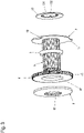
- At least one friction disk 8 arranged in a rotationally fixed and axially secured manner on the power shaft 6 is pushed onto the annular gear disk 4 .
- the toothed ring disk 4 is held by friction against rotation about the axis D on the at least one friction disk 8 .
- the frictional mounting of the toothed ring disk 4 relative to the power shaft 6 up to a predetermined torque M thus represents a cost-effective overload safety device for such a swivel fitting 1 that is less strong than an overload safety device designed as a separate structural unit.
- an inner peripheral edge 42 of the toothed ring disk 4 is conically shaped and pushed onto a cone 9 arranged on the power shaft 6 .
- one friction disk 8 presses against the toothed ring disk 4 on the side of the smaller diameter of the inner peripheral edge 42 of the toothed ring disk 4 .
- the cone 9 can be formed directly on the power shaft 6 .
- the cone 9 is mounted on the power shaft 6 .
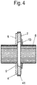
- the cone 9 is designed as a radially slotted clamping ring, as shown in figure 5 is shown.
- the cone 9 shown there has an internally toothed inner diameter 92 for non-rotatable attachment to the power shaft 6, which is provided with external teeth 61.
- the outer peripheral edge 91 of the cone 9 is conically shaped.
- the figure 5 shown cone 9 is formed with a slot 93.
- the friction disc 8 is pressed onto the cone 9
- the internal toothing of the cone 9 is pressed onto the external toothing of the power shaft 6, so that the cone 9 is fixed axially on the power shaft 6 in a clamping manner.
- the cone angle of the outer peripheral edge 91 of the cone 9 is preferably between 15° and 35°.
- the cone angle is particularly preferably between 20° and 30°.
- the friction disk 8 is preferably pressed onto the power shaft 6 with a press fit against the annular gear disk 4 .
- the at least one friction disc 8 is preferably designed as a plate spring.
- the predetermined torque M up to which the toothed ring disk 4 is frictionally held against rotation about the axis D by the at least one friction disk 8 is preferably at least 70 Nm, particularly preferably at least 80 Nm.
- the first control disk 7 is placed on the power shaft 6 on the side of the annular gear disk 4 facing away from the friction disk 8 .
- the first control disc 7 can be pivoted relative to the power shaft 6 and is secured axially by a spring element 13 in the manner of a disk spring.
- the spring element 13 is secured against rotation by teeth 132 on an inner circumference 131 of the spring element 13 on the power shaft 6 .
- the second control disk 11 is arranged on the side of the friction disk 8 facing away from the toothed ring disk 4 on the power shaft 6 .
- the second control disc 11 has a switching arm 111 and a slot 112 .
- a single tooth 113 meshes with the outer teeth of the power shaft 6 .
- the pawl 5 has a plurality of teeth 52 at a first end of a pawl arm 51 which, in use, engage the external toothing 41 of the toothed washer 4 .
- pivot bolts 53 protrude on both sides, with which the latch is pivotably fixed to pivot bolt receptacles 27 of the lever heads 23 of the first cover 2a and the second cover 2b.
- a recess 54 for receiving the switching contour 71 of the first control disk 7 is formed between the toothing 52 and the pivot pin 53 .
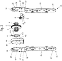
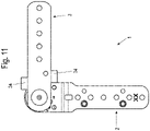
- control bolts 12 are fixed or formed on the covers 2a, 2b of the first lever 2 figures 8 and 9
- the embodiment variants shown hit the stop edges of a disk-shaped stop 15 in the respective end positions, the disk-shaped stop 15 being non-rotatably connected to the second lever 3 or the power shaft 6 .
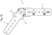
- these attacks are formed by lateral stops 34 on the second lever 3, as in the figures 11 and 12 is shown.
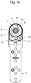
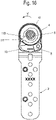
- figure 14 shows an example of a position of the swivel fitting 1 that has already been swiveled a little way in the adjustment direction V, in which the pawl 5 engages in the external toothing 41 of the toothed ring disk 4 .
- figure 15 shows a further pivoted position of the pivot fitting 1 in the adjustment direction V.
- the pawl 5 is always pressed here by the spring element 10 designed as a spring plate against the external toothing 41 of the toothed ring disk 4 .
- the alignment of the outer teeth 41 of the annular gear 4 and the teeth 52 of the pawl 5 is such that in the adjustment direction V the pawl 5 of Tooth to tooth of the external teeth 41 of the annular gear 4 can be moved.
- the switching arm 111 of the second control disc 11 has reached the outermost tooth of the toothing of the pawl 5 .
- the outermost tooth 52 is designed with a run-on bevel 55 .
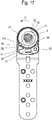
- the switching arm 111 can be pushed onto the outer teeth 52 of the pawl 5, as a result of which the teeth 52 of the pawl 5 disengage from the outer teeth 41 of the toothed ring disk 4, such as it in figure 17 is shown.
- control bolt 12 rests in the recess 72 of the first control disk 7 on the right-hand edge of this recess 72 .
- the switchover contour 71 of the first control disk 7 is pushed onto a tooth-free plane of the arm 51 of the pawl 5, so that the teeth 52 of the pawl 5 are still disengaged from the external toothing 41 of the toothed ring disks 4 remain and the swivel fitting 1 can be swiveled back into the starting position.
- the function of the overload protection is such that in any swiveling position of the levers 2, 3 of the swivel fitting 1 relative to one another from a torque M caused by the friction between the friction disc 8 and the toothed ring disc 4, the toothed ring disc 4 relative to the Friction disc 8 begins to slip about the axis of rotation D and the two levers 2, 3 can thus be pivoted relative to one another as long as the force exerted on the lever is greater than the predetermined torque M.
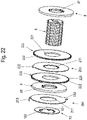
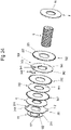
- the clamping mechanism has a plurality of toothed ring discs 202 , 302 arranged side by side on the power shaft 6 instead of the one toothed ring disc 4 .
- a friction disk 203 , 303 , 304 held non-rotatably on the power shaft 6 is arranged between two such toothed ring disks 202 , 302 .
- Each of these toothed washers 202, 302 has an annular inner peripheral edge 221, 321 and an outer toothing 222, 322, in which the pawl 5 engages.
- the friction disks 8 rest against the outer surfaces of the outer toothed ring disks 202, 302, pressing against the toothed ring disks 202, 302 in the axial direction.
- a first control disk 201, 301 is pushed onto the power shaft 6 on an outside of one of the friction disks 8.
- This first control disk 201, 301 also has an inner peripheral edge 211 in the form of a circular ring.
- the embodiment variant shown has a switchover contour 212, which has the same purpose as the switchover contour 71 of the first control disk 7 according to FIG figure 3 shown embodiment is used.
- a tab 213 is formed in the embodiment variant shown, which extends perpendicular to the plane of the control disk 201 in the direction of the plate-spring-like spring element 13 on the side of the first control disk 201 facing away from the toothed ring disks 202 .
- this tab 213 protrudes into a recess provided for this purpose on the first lever 2, which in this case has a slot-shaped recess instead of the control bolt 12, in which the tab 213 can be pivoted by a switching angle in the circumferential direction of the first control disk 201.
- Friction disk 8 shown has a switching contour 232 which extends radially outwards from the outer circumference of the friction disks 203 .
- the friction disks 203 also have an inner peripheral edge with internal teeth 231 analogously to the friction disks 8 .
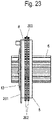
- the in the Figures 24 to 26 shown embodiment variant of a once again alternative clamping mechanism has analogous to that in the figures 20 and 21
- the embodiment variant shown preferably has three toothed ring discs 302, each with one friction disc 303, 304 arranged between two of the toothed ring discs 302.
- one of the friction disks 304 described above has an elevation 343 on its outer circumference 342, which is adjoined by a recess 344 for receiving a switching element 305.
- the switching element 305 is adapted to the inner contour of the recess 344 in such a way that it can be pivoted by a predetermined switching angle within the recess 344 about a pivot axis which is coaxial with the pivot axis of the power shaft 6 but is radially offset outside of the power shaft 6, such as it well in figure 26 can be seen.
- the recess 344 has an essentially v-shaped receiving area for receiving a v-shaped section of the switching element 305 .
- the circumferential width of a neck of the switching element 305 is dimensioned such that it can be pivoted within the recess 344 by a predetermined switching angle.
- the switching angle is preferably between 8° and 12°.
- the thickness of this switching element 305, viewed in the longitudinal direction of the power shaft 6, is less than the thickness of the friction disk 304.
- friction disk 304 is larger than the thickness of friction disk 303.
- the slightly smaller thickness of the switching element 305 compared to the friction disk 304 makes it possible in a simple manner to prevent the switching element 305 from being jammed by the friction disks 8 pressing against the annular gear disks 302 from the outside.
Landscapes
- Health & Medical Sciences (AREA)
- Dentistry (AREA)
- General Health & Medical Sciences (AREA)
- Chairs For Special Purposes, Such As Reclining Chairs (AREA)
- Pivots And Pivotal Connections (AREA)
Applications Claiming Priority (2)
| Application Number | Priority Date | Filing Date | Title |
|---|---|---|---|
| DE102019113248.7A DE102019113248A1 (de) | 2019-05-20 | 2019-05-20 | Schwenkbeschlag und Möbel |
| PCT/EP2020/063810 WO2020234236A1 (de) | 2019-05-20 | 2020-05-18 | Schwenkbeschlag und möbel |
Publications (2)
| Publication Number | Publication Date |
|---|---|
| EP3972452A1 EP3972452A1 (de) | 2022-03-30 |
| EP3972452B1 true EP3972452B1 (de) | 2022-09-07 |
Family
ID=70775400
Family Applications (1)
| Application Number | Title | Priority Date | Filing Date |
|---|---|---|---|
| EP20726813.7A Active EP3972452B1 (de) | 2019-05-20 | 2020-05-18 | Schwenkbeschlag und möbel |
Country Status (7)
| Country | Link |
|---|---|
| US (1) | US11839304B2 (pl) |
| EP (1) | EP3972452B1 (pl) |
| CN (1) | CN113853139B (pl) |
| DE (1) | DE102019113248A1 (pl) |
| ES (1) | ES2928694T3 (pl) |
| PL (1) | PL3972452T3 (pl) |
| WO (1) | WO2020234236A1 (pl) |
Families Citing this family (2)
| Publication number | Priority date | Publication date | Assignee | Title |
|---|---|---|---|---|
| DE102017110253B4 (de) * | 2017-05-11 | 2025-08-28 | Hettich Franke Gmbh & Co. Kg | Schwenkbeschlag und Möbel |
| DE102019119307A1 (de) * | 2019-07-16 | 2021-01-21 | Hettich Franke Gmbh & Co. Kg | Möbel und Verfahren zur Montage eines Möbels |
Family Cites Families (19)
| Publication number | Priority date | Publication date | Assignee | Title |
|---|---|---|---|---|
| US7093904B1 (en) * | 2005-08-29 | 2006-08-22 | Mcmillen Carl | Chair with fold-down arms for providing additional seating |
| US8216106B2 (en) * | 2009-05-29 | 2012-07-10 | Eaton Corporation | Locking differential side gear to friction disc unloading |
| SG182017A1 (en) * | 2010-12-16 | 2012-07-30 | Singapore Technologies Aerospace Ltd | A single arm adjustment mechanism for supporting an object |
| DE102011003175B4 (de) * | 2011-01-26 | 2020-06-04 | Seg Automotive Germany Gmbh | Startvorrichtung mit Überlastsicherung zum Andrehen von Verbrennungskraftmaschinen |
| DE102011017301B4 (de) * | 2011-04-15 | 2012-12-06 | Ferdinand Lusch Gmbh & Co. Kg | Rastbeschlag für ein Sitz- und/oder Liegemöbel |
| AT511329B1 (de) * | 2011-05-03 | 2012-11-15 | Blum Gmbh Julius | Verriegelbare ausstossvorrichtung mit überlastmechanismus |
| DE102011102442A1 (de) * | 2011-05-24 | 2012-11-29 | Kemmann & Koch Gmbh & Co. Kg | Gelenkbeschlag insbesondere für Möbel |
| CN202251726U (zh) * | 2011-08-15 | 2012-05-30 | 廖英洲 | 齿差动减速机结构 |
| EP2836392B1 (en) * | 2012-04-12 | 2020-03-04 | Magna Seating Inc. | Quick adjust continuously engaged recliner |
| DE102013104692B4 (de) | 2013-05-07 | 2014-12-31 | Ferdinand Lusch Gmbh & Co. Kg | Schwenkbeschlag für Sitz- und/oder Liegemöbel |
| JP5498608B1 (ja) * | 2013-05-20 | 2014-05-21 | 直伸 山下 | ソファー |
| WO2017057759A1 (ja) * | 2015-10-01 | 2017-04-06 | 向陽エンジニアリング株式会社 | 角度調整具 |
| DE202017101471U1 (de) * | 2017-03-14 | 2017-04-11 | Kemmann & Koch Gmbh & Co. Kg | Gelenkbeschlag insbesondere für Möbel |
| DE102017110250A1 (de) * | 2017-05-11 | 2018-11-15 | Hettich Franke Gmbh & Co. Kg | Schwenkbeschlag und Möbel |
| DE102017110246A1 (de) * | 2017-05-11 | 2018-11-15 | Hettich Franke Gmbh & Co. Kg | Schwenkbeschlag und Möbel |
| DE102017110247A1 (de) * | 2017-05-11 | 2018-11-15 | Hettich Franke Gmbh & Co. Kg | Schwenkbeschlag und Möbel |
| DE102017110248A1 (de) * | 2017-05-11 | 2018-11-15 | Hettich Franke Gmbh & Co. Kg | Schwenkbeschlag und Möbel |
| DE102017110253B4 (de) * | 2017-05-11 | 2025-08-28 | Hettich Franke Gmbh & Co. Kg | Schwenkbeschlag und Möbel |
| JP6553120B2 (ja) * | 2017-05-26 | 2019-07-31 | 長崎 守高 | アームレスト格納型車両シート |
-
2019
- 2019-05-20 DE DE102019113248.7A patent/DE102019113248A1/de not_active Withdrawn
-
2020
- 2020-05-18 WO PCT/EP2020/063810 patent/WO2020234236A1/de not_active Ceased
- 2020-05-18 CN CN202080037719.6A patent/CN113853139B/zh active Active
- 2020-05-18 ES ES20726813T patent/ES2928694T3/es active Active
- 2020-05-18 US US17/611,945 patent/US11839304B2/en active Active
- 2020-05-18 EP EP20726813.7A patent/EP3972452B1/de active Active
- 2020-05-18 PL PL20726813.7T patent/PL3972452T3/pl unknown
Also Published As
| Publication number | Publication date |
|---|---|
| US11839304B2 (en) | 2023-12-12 |
| CN113853139B (zh) | 2024-07-23 |
| WO2020234236A1 (de) | 2020-11-26 |
| PL3972452T3 (pl) | 2023-01-09 |
| US20220225770A1 (en) | 2022-07-21 |
| DE102019113248A1 (de) | 2020-11-26 |
| CN113853139A (zh) | 2021-12-28 |
| EP3972452A1 (de) | 2022-03-30 |
| ES2928694T3 (es) | 2022-11-22 |
Similar Documents
| Publication | Publication Date | Title |
|---|---|---|
| EP3621489B1 (de) | Schwenkbeschlag und möbel | |
| EP2880334B1 (de) | Ringmutter | |
| EP2544567B1 (de) | Rastbeschlag | |
| DE4313742C2 (de) | Bohrfutter | |
| DE19857199B4 (de) | Automatisch nachstellbare Reibungskupplung | |
| EP1530523B1 (de) | Armlehne | |
| EP1451035B1 (de) | Armlehne | |
| DE3412139A1 (de) | Stellmechanismus | |
| EP3972452B1 (de) | Schwenkbeschlag und möbel | |
| EP3400834A1 (de) | Schwenkbeschlag und möbel | |
| DE102011017301B4 (de) | Rastbeschlag für ein Sitz- und/oder Liegemöbel | |
| EP3621488B1 (de) | Schwenkbeschlag und möbel | |
| DE202010007993U1 (de) | Kupplungseinrichtung, insbesondere für Kraftfahrzeugsitzversteller | |
| EP3621486B1 (de) | Schwenkbeschlag und möbel | |
| WO2018206485A1 (de) | Schwenkbeschlag und möbel | |
| EP3498941A1 (de) | Betätigungshandhabe mit sperrvorrichtung | |
| DE102006032681B4 (de) | Gelenkbeschlag für Kraftfahrzeugsitze | |
| DE3028539C2 (pl) | ||
| EP3871563A1 (de) | Schwenkgelenk zum verstellen eines funktionsteils mit einem klemmelement | |
| DE3039968A1 (de) | Schaltwerk | |
| DE10223028A1 (de) | Halteelement | |
| EP0908350A2 (de) | Verstellmechanik für eine selbsthemmende Dreh-Verstellung eines Antriebs-Wirkteiles | |
| DE10011898C2 (de) | Beidseitig wirkender Antrieb | |
| DE29800270U1 (de) | Mit einer selbsttätigen Nachstelleinrichtung ausgestattete Handbremse für Kraftwagen | |
| DE1945766A1 (de) | Aussenrueckblickspiegel fuer Fahrzeuge,insbesondere Kraftfahrzeuge |
Legal Events
| Date | Code | Title | Description |
|---|---|---|---|
| STAA | Information on the status of an ep patent application or granted ep patent |
Free format text: STATUS: UNKNOWN |
|
| STAA | Information on the status of an ep patent application or granted ep patent |
Free format text: STATUS: THE INTERNATIONAL PUBLICATION HAS BEEN MADE |
|
| PUAI | Public reference made under article 153(3) epc to a published international application that has entered the european phase |
Free format text: ORIGINAL CODE: 0009012 |
|
| STAA | Information on the status of an ep patent application or granted ep patent |
Free format text: STATUS: REQUEST FOR EXAMINATION WAS MADE |
|
| 17P | Request for examination filed |
Effective date: 20211122 |
|
| AK | Designated contracting states |
Kind code of ref document: A1 Designated state(s): AL AT BE BG CH CY CZ DE DK EE ES FI FR GB GR HR HU IE IS IT LI LT LU LV MC MK MT NL NO PL PT RO RS SE SI SK SM TR |
|
| GRAP | Despatch of communication of intention to grant a patent |
Free format text: ORIGINAL CODE: EPIDOSNIGR1 |
|
| STAA | Information on the status of an ep patent application or granted ep patent |
Free format text: STATUS: GRANT OF PATENT IS INTENDED |
|
| DAV | Request for validation of the european patent (deleted) | ||
| DAX | Request for extension of the european patent (deleted) | ||
| INTG | Intention to grant announced |
Effective date: 20220525 |
|
| GRAS | Grant fee paid |
Free format text: ORIGINAL CODE: EPIDOSNIGR3 |
|
| GRAA | (expected) grant |
Free format text: ORIGINAL CODE: 0009210 |
|
| STAA | Information on the status of an ep patent application or granted ep patent |
Free format text: STATUS: THE PATENT HAS BEEN GRANTED |
|
| AK | Designated contracting states |
Kind code of ref document: B1 Designated state(s): AL AT BE BG CH CY CZ DE DK EE ES FI FR GB GR HR HU IE IS IT LI LT LU LV MC MK MT NL NO PL PT RO RS SE SI SK SM TR |
|
| REG | Reference to a national code |
Ref country code: GB Ref legal event code: FG4D Free format text: NOT ENGLISH |
|
| REG | Reference to a national code |
Ref country code: CH Ref legal event code: EP Ref country code: AT Ref legal event code: REF Ref document number: 1516351 Country of ref document: AT Kind code of ref document: T Effective date: 20220915 |
|
| REG | Reference to a national code |
Ref country code: IE Ref legal event code: FG4D Free format text: LANGUAGE OF EP DOCUMENT: GERMAN |
|
| REG | Reference to a national code |
Ref country code: DE Ref legal event code: R096 Ref document number: 502020001674 Country of ref document: DE |
|
| REG | Reference to a national code |
Ref country code: ES Ref legal event code: FG2A Ref document number: 2928694 Country of ref document: ES Kind code of ref document: T3 Effective date: 20221122 |
|
| REG | Reference to a national code |
Ref country code: LT Ref legal event code: MG9D |
|
| REG | Reference to a national code |
Ref country code: NL Ref legal event code: MP Effective date: 20220907 |
|
| PG25 | Lapsed in a contracting state [announced via postgrant information from national office to epo] |
Ref country code: SE Free format text: LAPSE BECAUSE OF FAILURE TO SUBMIT A TRANSLATION OF THE DESCRIPTION OR TO PAY THE FEE WITHIN THE PRESCRIBED TIME-LIMIT Effective date: 20220907 Ref country code: RS Free format text: LAPSE BECAUSE OF FAILURE TO SUBMIT A TRANSLATION OF THE DESCRIPTION OR TO PAY THE FEE WITHIN THE PRESCRIBED TIME-LIMIT Effective date: 20220907 Ref country code: NO Free format text: LAPSE BECAUSE OF FAILURE TO SUBMIT A TRANSLATION OF THE DESCRIPTION OR TO PAY THE FEE WITHIN THE PRESCRIBED TIME-LIMIT Effective date: 20221207 Ref country code: LV Free format text: LAPSE BECAUSE OF FAILURE TO SUBMIT A TRANSLATION OF THE DESCRIPTION OR TO PAY THE FEE WITHIN THE PRESCRIBED TIME-LIMIT Effective date: 20220907 Ref country code: LT Free format text: LAPSE BECAUSE OF FAILURE TO SUBMIT A TRANSLATION OF THE DESCRIPTION OR TO PAY THE FEE WITHIN THE PRESCRIBED TIME-LIMIT Effective date: 20220907 Ref country code: FI Free format text: LAPSE BECAUSE OF FAILURE TO SUBMIT A TRANSLATION OF THE DESCRIPTION OR TO PAY THE FEE WITHIN THE PRESCRIBED TIME-LIMIT Effective date: 20220907 |
|
| PG25 | Lapsed in a contracting state [announced via postgrant information from national office to epo] |
Ref country code: HR Free format text: LAPSE BECAUSE OF FAILURE TO SUBMIT A TRANSLATION OF THE DESCRIPTION OR TO PAY THE FEE WITHIN THE PRESCRIBED TIME-LIMIT Effective date: 20220907 Ref country code: GR Free format text: LAPSE BECAUSE OF FAILURE TO SUBMIT A TRANSLATION OF THE DESCRIPTION OR TO PAY THE FEE WITHIN THE PRESCRIBED TIME-LIMIT Effective date: 20221208 |
|
| PG25 | Lapsed in a contracting state [announced via postgrant information from national office to epo] |
Ref country code: SM Free format text: LAPSE BECAUSE OF FAILURE TO SUBMIT A TRANSLATION OF THE DESCRIPTION OR TO PAY THE FEE WITHIN THE PRESCRIBED TIME-LIMIT Effective date: 20220907 Ref country code: RO Free format text: LAPSE BECAUSE OF FAILURE TO SUBMIT A TRANSLATION OF THE DESCRIPTION OR TO PAY THE FEE WITHIN THE PRESCRIBED TIME-LIMIT Effective date: 20220907 Ref country code: PT Free format text: LAPSE BECAUSE OF FAILURE TO SUBMIT A TRANSLATION OF THE DESCRIPTION OR TO PAY THE FEE WITHIN THE PRESCRIBED TIME-LIMIT Effective date: 20230109 Ref country code: CZ Free format text: LAPSE BECAUSE OF FAILURE TO SUBMIT A TRANSLATION OF THE DESCRIPTION OR TO PAY THE FEE WITHIN THE PRESCRIBED TIME-LIMIT Effective date: 20220907 |
|
| PG25 | Lapsed in a contracting state [announced via postgrant information from national office to epo] |
Ref country code: SK Free format text: LAPSE BECAUSE OF FAILURE TO SUBMIT A TRANSLATION OF THE DESCRIPTION OR TO PAY THE FEE WITHIN THE PRESCRIBED TIME-LIMIT Effective date: 20220907 Ref country code: IS Free format text: LAPSE BECAUSE OF FAILURE TO SUBMIT A TRANSLATION OF THE DESCRIPTION OR TO PAY THE FEE WITHIN THE PRESCRIBED TIME-LIMIT Effective date: 20230107 Ref country code: EE Free format text: LAPSE BECAUSE OF FAILURE TO SUBMIT A TRANSLATION OF THE DESCRIPTION OR TO PAY THE FEE WITHIN THE PRESCRIBED TIME-LIMIT Effective date: 20220907 |
|
| REG | Reference to a national code |
Ref country code: DE Ref legal event code: R097 Ref document number: 502020001674 Country of ref document: DE |
|
| P01 | Opt-out of the competence of the unified patent court (upc) registered |
Effective date: 20230408 |
|
| PG25 | Lapsed in a contracting state [announced via postgrant information from national office to epo] |
Ref country code: NL Free format text: LAPSE BECAUSE OF FAILURE TO SUBMIT A TRANSLATION OF THE DESCRIPTION OR TO PAY THE FEE WITHIN THE PRESCRIBED TIME-LIMIT Effective date: 20220907 Ref country code: AL Free format text: LAPSE BECAUSE OF FAILURE TO SUBMIT A TRANSLATION OF THE DESCRIPTION OR TO PAY THE FEE WITHIN THE PRESCRIBED TIME-LIMIT Effective date: 20220907 |
|
| PLBE | No opposition filed within time limit |
Free format text: ORIGINAL CODE: 0009261 |
|
| STAA | Information on the status of an ep patent application or granted ep patent |
Free format text: STATUS: NO OPPOSITION FILED WITHIN TIME LIMIT |
|
| PG25 | Lapsed in a contracting state [announced via postgrant information from national office to epo] |
Ref country code: DK Free format text: LAPSE BECAUSE OF FAILURE TO SUBMIT A TRANSLATION OF THE DESCRIPTION OR TO PAY THE FEE WITHIN THE PRESCRIBED TIME-LIMIT Effective date: 20220907 |
|
| 26N | No opposition filed |
Effective date: 20230608 |
|
| REG | Reference to a national code |
Ref country code: CH Ref legal event code: PL |
|
| PG25 | Lapsed in a contracting state [announced via postgrant information from national office to epo] |
Ref country code: MC Free format text: LAPSE BECAUSE OF FAILURE TO SUBMIT A TRANSLATION OF THE DESCRIPTION OR TO PAY THE FEE WITHIN THE PRESCRIBED TIME-LIMIT Effective date: 20220907 |
|
| REG | Reference to a national code |
Ref country code: BE Ref legal event code: MM Effective date: 20230531 |
|
| PG25 | Lapsed in a contracting state [announced via postgrant information from national office to epo] |
Ref country code: MC Free format text: LAPSE BECAUSE OF FAILURE TO SUBMIT A TRANSLATION OF THE DESCRIPTION OR TO PAY THE FEE WITHIN THE PRESCRIBED TIME-LIMIT Effective date: 20220907 Ref country code: LU Free format text: LAPSE BECAUSE OF NON-PAYMENT OF DUE FEES Effective date: 20230518 Ref country code: LI Free format text: LAPSE BECAUSE OF NON-PAYMENT OF DUE FEES Effective date: 20230531 Ref country code: CH Free format text: LAPSE BECAUSE OF NON-PAYMENT OF DUE FEES Effective date: 20230531 |
|
| REG | Reference to a national code |
Ref country code: IE Ref legal event code: MM4A |
|
| PG25 | Lapsed in a contracting state [announced via postgrant information from national office to epo] |
Ref country code: IE Free format text: LAPSE BECAUSE OF NON-PAYMENT OF DUE FEES Effective date: 20230518 |
|
| PG25 | Lapsed in a contracting state [announced via postgrant information from national office to epo] |
Ref country code: IE Free format text: LAPSE BECAUSE OF NON-PAYMENT OF DUE FEES Effective date: 20230518 |
|
| PG25 | Lapsed in a contracting state [announced via postgrant information from national office to epo] |
Ref country code: BE Free format text: LAPSE BECAUSE OF NON-PAYMENT OF DUE FEES Effective date: 20230531 |
|
| PGFP | Annual fee paid to national office [announced via postgrant information from national office to epo] |
Ref country code: ES Payment date: 20240614 Year of fee payment: 5 |
|
| PGFP | Annual fee paid to national office [announced via postgrant information from national office to epo] |
Ref country code: FR Payment date: 20240522 Year of fee payment: 5 |
|
| PGFP | Annual fee paid to national office [announced via postgrant information from national office to epo] |
Ref country code: TR Payment date: 20240508 Year of fee payment: 5 |
|
| PG25 | Lapsed in a contracting state [announced via postgrant information from national office to epo] |
Ref country code: BG Free format text: LAPSE BECAUSE OF FAILURE TO SUBMIT A TRANSLATION OF THE DESCRIPTION OR TO PAY THE FEE WITHIN THE PRESCRIBED TIME-LIMIT Effective date: 20220907 |
|
| PG25 | Lapsed in a contracting state [announced via postgrant information from national office to epo] |
Ref country code: BG Free format text: LAPSE BECAUSE OF FAILURE TO SUBMIT A TRANSLATION OF THE DESCRIPTION OR TO PAY THE FEE WITHIN THE PRESCRIBED TIME-LIMIT Effective date: 20220907 |
|
| GBPC | Gb: european patent ceased through non-payment of renewal fee |
Effective date: 20240518 |
|
| PG25 | Lapsed in a contracting state [announced via postgrant information from national office to epo] |
Ref country code: GB Free format text: LAPSE BECAUSE OF NON-PAYMENT OF DUE FEES Effective date: 20240518 |
|
| PGFP | Annual fee paid to national office [announced via postgrant information from national office to epo] |
Ref country code: PL Payment date: 20250430 Year of fee payment: 6 Ref country code: DE Payment date: 20250519 Year of fee payment: 6 |
|
| PGFP | Annual fee paid to national office [announced via postgrant information from national office to epo] |
Ref country code: IT Payment date: 20250530 Year of fee payment: 6 |
|
| PGFP | Annual fee paid to national office [announced via postgrant information from national office to epo] |
Ref country code: AT Payment date: 20250721 Year of fee payment: 5 |
|
| PG25 | Lapsed in a contracting state [announced via postgrant information from national office to epo] |
Ref country code: CY Free format text: LAPSE BECAUSE OF FAILURE TO SUBMIT A TRANSLATION OF THE DESCRIPTION OR TO PAY THE FEE WITHIN THE PRESCRIBED TIME-LIMIT; INVALID AB INITIO Effective date: 20200518 |
|
| PG25 | Lapsed in a contracting state [announced via postgrant information from national office to epo] |
Ref country code: HU Free format text: LAPSE BECAUSE OF FAILURE TO SUBMIT A TRANSLATION OF THE DESCRIPTION OR TO PAY THE FEE WITHIN THE PRESCRIBED TIME-LIMIT; INVALID AB INITIO Effective date: 20200518 |
|
| PG25 | Lapsed in a contracting state [announced via postgrant information from national office to epo] |
Ref country code: SI Free format text: LAPSE BECAUSE OF FAILURE TO SUBMIT A TRANSLATION OF THE DESCRIPTION OR TO PAY THE FEE WITHIN THE PRESCRIBED TIME-LIMIT Effective date: 20220907 |