EP3971411A1 - Starteranbau - Google Patents
Starteranbau Download PDFInfo
- Publication number
- EP3971411A1 EP3971411A1 EP21000261.4A EP21000261A EP3971411A1 EP 3971411 A1 EP3971411 A1 EP 3971411A1 EP 21000261 A EP21000261 A EP 21000261A EP 3971411 A1 EP3971411 A1 EP 3971411A1
- Authority
- EP
- European Patent Office
- Prior art keywords
- starter
- combustion engine
- internal combustion
- holder
- engine according
- Prior art date
- Legal status (The legal status is an assumption and is not a legal conclusion. Google has not performed a legal analysis and makes no representation as to the accuracy of the status listed.)
- Granted
Links
Images

Classifications
-
- F—MECHANICAL ENGINEERING; LIGHTING; HEATING; WEAPONS; BLASTING
- F02—COMBUSTION ENGINES; HOT-GAS OR COMBUSTION-PRODUCT ENGINE PLANTS
- F02N—STARTING OF COMBUSTION ENGINES; STARTING AIDS FOR SUCH ENGINES, NOT OTHERWISE PROVIDED FOR
- F02N11/00—Starting of engines by means of electric motors
-
- F—MECHANICAL ENGINEERING; LIGHTING; HEATING; WEAPONS; BLASTING
- F02—COMBUSTION ENGINES; HOT-GAS OR COMBUSTION-PRODUCT ENGINE PLANTS
- F02N—STARTING OF COMBUSTION ENGINES; STARTING AIDS FOR SUCH ENGINES, NOT OTHERWISE PROVIDED FOR
- F02N15/00—Other power-operated starting apparatus; Component parts, details, or accessories, not provided for in, or of interest apart from groups F02N5/00 - F02N13/00
- F02N15/006—Assembling or mounting of starting devices
-
- F—MECHANICAL ENGINEERING; LIGHTING; HEATING; WEAPONS; BLASTING
- F02—COMBUSTION ENGINES; HOT-GAS OR COMBUSTION-PRODUCT ENGINE PLANTS
- F02N—STARTING OF COMBUSTION ENGINES; STARTING AIDS FOR SUCH ENGINES, NOT OTHERWISE PROVIDED FOR
- F02N11/00—Starting of engines by means of electric motors
- F02N11/04—Starting of engines by means of electric motors the motors being associated with current generators
Definitions
- the invention relates to an internal combustion engine with a universal mount on an electric starter, in particular for laying the cable harness.
- Starter devices are known in which the starter is screwed to a flange face perpendicular to the starter axis.
- the fastening screws are screwed axially to the starter axle.
- cable harness attachments are known, which are implemented via slugs on the crankcase of the internal combustion engine below the starter by means of individual sheet metal holders.
- the solution to the problem provides an internal combustion engine comprising at least one starter with a starter gear which is arranged at the opposite end of the crankshaft or at the same end in order to transmit the rotation of the starter to the crankshaft, the starter being attached to the crankcase of the internal combustion engine and wherein the starter is inserted into a receiving bore and is arranged so that it can be fastened to the crankcase with at least one screw, and wherein a holder is arranged on the starter.
- the advantage here is that the accessibility of the fastening screws is significantly improved, while at the same time there is no unnecessary accumulation of material on the crankcase.
- a further development according to the invention provides that at least one support plate is arranged at the starter end.
- the advantage here is that especially with longer starters, the tendency to oscillate is reduced or prevented.
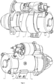
- FIG 1 shows a starter 1 which is connected to the crankcase 4 in a removable manner by means of two screws 2 and which has a holder 5 which is fastened to two guide rods 6 and which has a locking mandrel 8 which engages in a corresponding depression in the outer skin of the starter, so that the Holder is not slidably arranged on the starter 1.
- the holder 5 has two receiving bores 7 into which a support plate 3 can be screwed, which is suitable for receiving cable harnesses and/or fluid pipes.
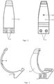
- FIG 2 a holder 5 with locking mandrel 8 and mounting holes 7 is shown.
- the holder 5 is fastened to two guide rods 6 and has a locking mandrel 8 which engages in a corresponding depression in the outer skin of the starter, so that the holder is not arranged on the starter 1 in a displaceable manner.
- the holder 5 has two receiving bores 7 into which a support plate 3 can be screwed, which is suitable for receiving cable harnesses and/or fluid pipes.
- figure 3 12 shows a side view of the holder 5 from FIG figure 1 .
- the holder 5 is attached to the starter 1 on two guide rods by means of the attachment contour 6 hooked and has a locking mandrel 8, which engages in a corresponding recess of the starter outer skin, so that the holder is not slidably arranged on the starter 1.
- the holder 5 has two receiving bores 7 into which a support plate 3 can be screwed, which is suitable for receiving cable harnesses and/or fluid pipes.
- figure 4 shows a starter with holder, support plate and cable harness arranged on the support plate.
- the holder 5 is attached to two guide rods 6 by means of the attachment contour for attachment to the starter 1 and has a locking mandrel 8 which engages in a corresponding depression in the outer skin of the starter, so that the holder is not arranged on the starter 1 in a displaceable manner.
- the holder 5 has two receiving bores 7 into which a support plate 3 can be screwed, which is suitable for receiving cable harnesses and/or fluid pipes.
- An additional support plate can be attached to the starter end to reduce any vibrations that may occur in the free end of the starter.
Landscapes
- Engineering & Computer Science (AREA)
- Chemical & Material Sciences (AREA)
- Combustion & Propulsion (AREA)
- Mechanical Engineering (AREA)
- General Engineering & Computer Science (AREA)
- Cylinder Crankcases Of Internal Combustion Engines (AREA)
Abstract
2. Beschrieben wird eine Brennkraftmaschine, umfassend wenigstens einem Starter (1) mit einem Startergetriebe, das am entgegengesetzten Ende der Kurbelwelle oder am selben Ende angeordnet ist, um die Drehung des Starters (1) auf die Kurbelwelle zu übertragen, wobei der Starter (1) am Kurbelgehäuse (4) der Brennkraftmaschine angebracht ist und wobei der Starter (1) in eine Aufnahmebohrung (7) gesteckt und mit wenigstens einer Schraube (2) am Kurbelgehäuse (4) befestigbar angeordnet ist und wobei am Starter (1) ein Halter (5) angeordnet ist.
Description
- Die Erfindung betrifft eine Brennkraftmaschine mit einer Universalhalterung an einem Elektrostarter, insbesondere zur Kabelbaumverlegung.
- Bekannt sind Startervorrichtungen, bei denen der Starter an einer Flanschfläche mit senkrechter Ausrichtung zur Starterachse verschraubt ist. Die Befestigungsschrauben werden hierbei axial zur Starterachse verschraubt. Weiter sind Kabelbaumbefestigungen bekannt, die über Butzen am Kurbelgehäuse der Brennkraftmaschine unterhalb des Starters mittels einzelner Blechhalter realisiert werden.
- Dies ist nachteilig, da es zusätzliche Butzen benötigt, die eigentlich gar nicht erforderlich wären.
- Es ist somit die Aufgabe der vorliegenden Erfindung, die oben genannten Nachteile zu vermeiden.
- Die Lösung der Aufgabe sieht eine Brennkraftmaschine vor, umfassend wenigstens einen Starter mit einem Startergetriebe, das am entgegengesetzten Ende der Kurbelwelle oder am selben Ende angeordnet ist, um die Drehung des Starters auf die Kurbelwelle zu übertragen, wobei der Starter am Kurbelgehäuse der Brennkraftmaschine angebracht ist und wobei der Starter in eine Aufnahmebohrung gesteckt und mit wenigstens einer Schraube am Kurbelgehäuse befestigbar angeordnet ist und wobei am Starter ein Halter angeordnet ist. Hierbei ist von Vorteil, dass die Zugänglichkeit der Befestigungsschrauben deutlich verbessert ist, bei gleichzeitigem Verzicht auf unnötige Materialansammlungen am Kurbelgehäuse.
- Eine weitere erfindungsgemäße Weiterbildung sieht vor, dass wenigstens ein Abstützblech am Starterende angeordnet ist. Der Vorteil hierbei ist, dass insbesondere bei längeren Startern die Schwingungsneigung reduziert oder verhindert wird.
- Weitere vorteilhafte Weiterbildungen sind in den Unteransprüchen enthalten.
- Die Erfindung wird anhand von Ausführungsbeispielen unter Hinweis auf die beigefügten Zeichnungen näher erläutert. Es zeigen:
- Figur 1
- eine Starteranordnung mit Halter,
- Figur 2
- einen Halter mit Arretierungsdorn und Aufnahmebohrung,
- Figur 3
- eine Seitenansicht des Halters aus
Figur 1 , - Figur 4
- einen Starter mit Halter, Abstützblech und am Abstützblech angeordnetem Kabelbaum.
-
Figur 1 zeigt einen Starter 1, der mittels zweier Schrauben 2 mit dem Kurbelgehäuse 4 demontierbar verbunden ist und der einen Halter 5 aufweist, der an zwei Führungsstäben 6 befestigt ist und der einen Arretierungsdorn 8 aufweist, der in eine korrespondierende Vertiefung der Starteraußenhaut eingreift, so dass der Halter nicht verschiebbar am Starter 1 angeordnet ist. Der Halter 5 weist zwei Aufnahmebohrungen 7 auf, in die ein Abstützblech 3 eingeschraubt werden kann, das zur Aufnahme von Kabelbäumen und/ oder Fluidrohren geeignet ist. - In
Figur 2 wird ein Halter 5 mit Arretierungsdorn 8 und Aufnahmebohrungen 7 dargestellt. Der Halter 5 ist an zwei Führungsstäben 6 befestigt und weist einen Arretierungsdorn 8 auf, der in eine korrespondierende Vertiefung der Starteraußenhaut eingreift, so dass der Halter nicht verschiebbar am Starter 1 angeordnet ist. Der Halter 5 weist zwei Aufnahmebohrungen 7 auf, in die ein Abstützblech 3 eingeschraubt werden kann, das zur Aufnahme von Kabelbäumen und/oder Fluidrohren geeignet ist. -
Figur 3 zeigt eine Seitenansicht des Halters 5 ausFigur 1 . Der Halter 5 ist mittels der Einhängekontur zur Befestigung am Starter 1 an zwei Führungsstäben 6 eingehängt und weist einen Arretierungsdorn 8 auf, der in eine korrespondierende Vertiefung der Starteraußenhaut eingreift, so dass der Halter nicht verschiebbar am Starter 1 angeordnet ist. Der Halter 5 weist zwei Aufnahmebohrungen 7 auf, in die ein Abstützblech 3 eingeschraubt werden kann, das zur Aufnahme von Kabelbäumen und/oder Fluidrohren geeignet ist. -
Figur 4 zeigt einen Starter mit Halter, Abstützblech und am Abstützblech angeordnetem Kabelbaum. Der Halter 5 ist mittels der Einhängekontur zur Befestigung am Starter 1 an zwei Führungsstäben 6 eingehängt und weist einen Arretierungsdorn 8 auf, der in eine korrespondierende Vertiefung der Starteraußenhaut eingreift, so dass der Halter nicht verschiebbar am Starter 1 angeordnet ist. Der Halter 5 weist zwei Aufnahmebohrungen 7 auf, in die ein Abstützblech 3 eingeschraubt werden kann, das zur Aufnahme von Kabelbäumen und/oder Fluidrohren geeignet ist. - Um möglicherweise auftretende Schwingungen des freien Starterendes zu reduzieren, kann ein zusätzliches Abstützblech am Starterende angebracht werden.
-
- 1
- Starter
- 2
- Schraube
- 3
- Abstützblech
- 4
- Kurbelgehäuse
- 5
- Halter
- 6
- Führungsstäbe
- 7
- Aufnahmebohrung
- 8
- Arretierungsdorn
Claims (10)
- Brennkraftmaschine, umfassend wenigstens einem Starter (1) mit einem Startergetriebe, das am entgegengesetzten Ende der Kurbelwelle oder am selben Ende angeordnet ist, um die Drehung des Starters (1) auf die Kurbelwelle zu übertragen, wobei der Starter (1) am Kurbelgehäuse (4) der Brennkraftmaschine angebracht ist und wobei der Starter (1) in eine Aufnahmebohrung (7) gesteckt und mit wenigstens einer Schraube (2) am Kurbelgehäuse (4) befestigbar angeordnet ist und wobei am Starter (1) ein Halter (5) angeordnet ist.
- Brennkraftmaschine nach Anspruch 1,
dadurch gekennzeichnet, dass der Halter (5) am Starter (1) mit Führungsstäben (6) befestigt ist. - Brennkraftmaschine nach Anspruch 1 oder 2,
dadurch gekennzeichnet, dass der Halter (5) am Starter (1) aus Kunststoff besteht. - Brennkraftmaschine nach einem oder mehreren der vorgenannten Ansprüche,
dadurch gekennzeichnet, dass der Halter (5) wenigstens eine Aufnahmebohrung (7) aufweist. - Brennkraftmaschine nach einem oder mehreren der vorgenannten Ansprüche,
dadurch gekennzeichnet, dass der Starter (1) mittels wenigstens zweier Schrauben (2) mit der Brennkraftmaschine verbunden ist. - Brennkraftmaschine nach einem oder mehreren der vorgenannten Ansprüche,
dadurch gekennzeichnet, dass der Halter (5) einen Arretierungsdorn (8) aufweist, der in eine korrespondierende Vertiefung in der Außenfläche des Starters (1) eingreift. - Brennkraftmaschine nach einem oder mehreren der vorgenannten Ansprüche,
dadurch gekennzeichnet, dass wenigstens ein Abstützblech am Starterende angeordnet ist. - Brennkraftmaschine nach einem oder mehreren der vorgenannten Ansprüche,
dadurch gekennzeichnet, dass der Halter (5) wenigstens eine Aufnahmebohrung (7) aufweist, in der ein Abstützblech (3) montiert ist, insbesondere zur Aufnahme von Kabeln oder Rohren. - Brennkraftmaschine nach einem oder mehreren der vorgenannten Ansprüche,
dadurch gekennzeichnet, dass der Starter ein Generator ist. - Brennkraftmaschine nach einem oder mehreren der vorgenannten Ansprüche,
dadurch gekennzeichnet, dass die Führungsstäbe (6) die Starterpakethalteschrauben des Starters (1) sind.
Applications Claiming Priority (1)
| Application Number | Priority Date | Filing Date | Title |
|---|---|---|---|
| DE102020005721.7A DE102020005721A1 (de) | 2020-09-18 | 2020-09-18 | Starteranbau |
Publications (2)
| Publication Number | Publication Date |
|---|---|
| EP3971411A1 true EP3971411A1 (de) | 2022-03-23 |
| EP3971411B1 EP3971411B1 (de) | 2025-07-09 |
Family
ID=77801433
Family Applications (1)
| Application Number | Title | Priority Date | Filing Date |
|---|---|---|---|
| EP21000261.4A Active EP3971411B1 (de) | 2020-09-18 | 2021-09-15 | Starteranbau |
Country Status (4)
| Country | Link |
|---|---|
| US (1) | US11512675B2 (de) |
| EP (1) | EP3971411B1 (de) |
| CN (1) | CN114198234B (de) |
| DE (1) | DE102020005721A1 (de) |
Cited By (1)
| Publication number | Priority date | Publication date | Assignee | Title |
|---|---|---|---|---|
| CN115342244A (zh) * | 2022-08-22 | 2022-11-15 | 浙江迦南科技股份有限公司 | 一种可居中卡固稳定便于拆装的清洗管 |
Citations (6)
| Publication number | Priority date | Publication date | Assignee | Title |
|---|---|---|---|---|
| US2760377A (en) * | 1954-11-02 | 1956-08-28 | Leta Collins | Starting motor attachment |
| US3536051A (en) * | 1968-03-11 | 1970-10-27 | Eaton Stamping Co | Electric starting system for small engines |
| DE102006021239A1 (de) * | 2006-05-06 | 2007-11-22 | Bayerische Motoren Werke Ag | Befestigungsanordnung für Nebenaggregate |
| CN102042390A (zh) * | 2009-10-15 | 2011-05-04 | 通用汽车环球科技运作公司 | 用于动力传动系安装部件的灵活安装系统 |
| CN108884760A (zh) * | 2016-04-08 | 2018-11-23 | 洋马株式会社 | 发动机装置 |
| CN111441890A (zh) * | 2020-05-21 | 2020-07-24 | 西北工业大学 | 一种用于中小型无人机的二冲程四缸活塞发动机起动装置 |
Family Cites Families (13)
| Publication number | Priority date | Publication date | Assignee | Title |
|---|---|---|---|---|
| US1905836A (en) * | 1928-05-19 | 1933-04-25 | Briggs & Stratton Corp | Engine starter |
| US2074110A (en) * | 1935-01-28 | 1937-03-16 | Gruenberger Otto | Automatic starter for internal combustion engines |
| JPS477770Y1 (de) * | 1968-09-24 | 1972-03-24 | ||
| US4155266A (en) * | 1977-10-28 | 1979-05-22 | Bradley James L | Support housing for adapting automobile starter motors to aircraft engines |
| US4336975A (en) * | 1980-03-27 | 1982-06-29 | Casteel Ronald C | Automotive electrical harness |
| US5207195A (en) * | 1992-07-29 | 1993-05-04 | Mcclintic Rdm, Inc. | Combined starter conversion and oil filter adapter |
| JP3994926B2 (ja) * | 2003-06-04 | 2007-10-24 | 日産自動車株式会社 | スタータ取付構造 |
| JP5091062B2 (ja) * | 2008-09-02 | 2012-12-05 | 本田技研工業株式会社 | 車両用エンジン |
| JP5463946B2 (ja) * | 2010-02-18 | 2014-04-09 | 株式会社デンソー | スタータ |
| CA3027536C (en) * | 2010-09-23 | 2022-04-12 | Polaris Industries Inc. | Engine |
| US20150102692A1 (en) * | 2013-10-10 | 2015-04-16 | Kyungshin Industrial Co., Ltd. | Terminal assembly for starter motor of vehicle |
| JP2015074384A (ja) * | 2013-10-10 | 2015-04-20 | ヤマハ発動機株式会社 | 鞍乗型車両 |
| DE102016004077B4 (de) * | 2016-04-08 | 2020-02-13 | Deutz Aktiengesellschaft | Starter |
-
2020
- 2020-09-18 DE DE102020005721.7A patent/DE102020005721A1/de active Pending
-
2021
- 2021-09-14 US US17/474,880 patent/US11512675B2/en active Active
- 2021-09-15 EP EP21000261.4A patent/EP3971411B1/de active Active
- 2021-09-18 CN CN202111097766.2A patent/CN114198234B/zh active Active
Patent Citations (6)
| Publication number | Priority date | Publication date | Assignee | Title |
|---|---|---|---|---|
| US2760377A (en) * | 1954-11-02 | 1956-08-28 | Leta Collins | Starting motor attachment |
| US3536051A (en) * | 1968-03-11 | 1970-10-27 | Eaton Stamping Co | Electric starting system for small engines |
| DE102006021239A1 (de) * | 2006-05-06 | 2007-11-22 | Bayerische Motoren Werke Ag | Befestigungsanordnung für Nebenaggregate |
| CN102042390A (zh) * | 2009-10-15 | 2011-05-04 | 通用汽车环球科技运作公司 | 用于动力传动系安装部件的灵活安装系统 |
| CN108884760A (zh) * | 2016-04-08 | 2018-11-23 | 洋马株式会社 | 发动机装置 |
| CN111441890A (zh) * | 2020-05-21 | 2020-07-24 | 西北工业大学 | 一种用于中小型无人机的二冲程四缸活塞发动机起动装置 |
Cited By (1)
| Publication number | Priority date | Publication date | Assignee | Title |
|---|---|---|---|---|
| CN115342244A (zh) * | 2022-08-22 | 2022-11-15 | 浙江迦南科技股份有限公司 | 一种可居中卡固稳定便于拆装的清洗管 |
Also Published As
| Publication number | Publication date |
|---|---|
| DE102020005721A1 (de) | 2022-03-24 |
| US11512675B2 (en) | 2022-11-29 |
| CN114198234B (zh) | 2025-02-11 |
| US20220090572A1 (en) | 2022-03-24 |
| CN114198234A (zh) | 2022-03-18 |
| EP3971411B1 (de) | 2025-07-09 |
Similar Documents
| Publication | Publication Date | Title |
|---|---|---|
| DE102016223510A1 (de) | Trägervorrichtung für einen Verbrennungsmotor eines Fahrzeugs | |
| DE112017006116T5 (de) | Montagehalterung | |
| DE3122533A1 (de) | Brennkraftmaschine | |
| EP3971411A1 (de) | Starteranbau | |
| DE3138165A1 (de) | "hubkolbenbrennkratfmaschine, vorzugsweise vierzylindriger bauart" | |
| EP0553471A2 (de) | Riemenantrieb von elektrischen Maschinen | |
| DE102021100207A1 (de) | Konstruktion und Verfahren zur Montage einer Vorrichtung | |
| WO2007118558A1 (de) | Halterung für ein motor-pumpen-aggregat, insbesondere für eine servolenkung | |
| DE3313140A1 (de) | Kette fuer eine maschinenanlage der spanabhebenden bearbeitung | |
| DE102018005100A1 (de) | Werkzeug zur Montage eines Schwingungstilgers auf einer Kurbelwelle | |
| DE102018106987A1 (de) | Achsparalleles Hybridmodul mit Kettentrieb und Spannsystem | |
| DE19614677C2 (de) | Kurbelwelle, insbesondere für Einzylinder-Verbrennungsmotoren | |
| DE3323562A1 (de) | Einspritzleitungshalterung an einer mehrzylindrigen brennkraftmaschine | |
| DE102021106098B3 (de) | Halterung zur Befestigung einer Pumpe | |
| DE102023200937A1 (de) | Thermomanagementmodul | |
| DE102022130106B4 (de) | Ausrückeinheit mit Fluidleitung für eine Kupplung | |
| DE102017129152A1 (de) | Auflösewalze für eine Offenend-Spinnvorrichtung sowie Offenend-Spinnvorrichtung | |
| DE102016004077B4 (de) | Starter | |
| DE102014009558A1 (de) | Halteanordnung zum schwingungsentkoppelten Befestigen zweier Bauteile | |
| DE112015001284B4 (de) | Anbringungsstruktur für ein Kraftmaschinenzubehör | |
| DE102019007007A1 (de) | Brennkraftmaschine mit einem Zylinderkurbelgehäuse und einem Zylinderkopf mit integriertem höhenverstellbarem Lüfteranbau für elastische Keilrippenriemen | |
| DE10354105B4 (de) | Halter für ein Kraftfahrzeug-Nebenaggregat | |
| DE102015012498B4 (de) | Kettentrieb-Baugruppe mit Spannschienen-Montagehilfe | |
| DE102009054938A1 (de) | Kraftstoffhochdruckpumpe | |
| DE102012000884A1 (de) | Motorblock für eine Brennkraftmaschine eines Kraftfahrzeugs |
Legal Events
| Date | Code | Title | Description |
|---|---|---|---|
| PUAI | Public reference made under article 153(3) epc to a published international application that has entered the european phase |
Free format text: ORIGINAL CODE: 0009012 |
|
| STAA | Information on the status of an ep patent application or granted ep patent |
Free format text: STATUS: THE APPLICATION HAS BEEN PUBLISHED |
|
| AK | Designated contracting states |
Kind code of ref document: A1 Designated state(s): AL AT BE BG CH CY CZ DE DK EE ES FI FR GB GR HR HU IE IS IT LI LT LU LV MC MK MT NL NO PL PT RO RS SE SI SK SM TR |
|
| STAA | Information on the status of an ep patent application or granted ep patent |
Free format text: STATUS: REQUEST FOR EXAMINATION WAS MADE |
|
| 17P | Request for examination filed |
Effective date: 20220831 |
|
| RBV | Designated contracting states (corrected) |
Designated state(s): AL AT BE BG CH CY CZ DE DK EE ES FI FR GB GR HR HU IE IS IT LI LT LU LV MC MK MT NL NO PL PT RO RS SE SI SK SM TR |
|
| STAA | Information on the status of an ep patent application or granted ep patent |
Free format text: STATUS: EXAMINATION IS IN PROGRESS |
|
| 17Q | First examination report despatched |
Effective date: 20231220 |
|
| GRAP | Despatch of communication of intention to grant a patent |
Free format text: ORIGINAL CODE: EPIDOSNIGR1 |
|
| STAA | Information on the status of an ep patent application or granted ep patent |
Free format text: STATUS: GRANT OF PATENT IS INTENDED |
|
| INTG | Intention to grant announced |
Effective date: 20250228 |
|
| GRAS | Grant fee paid |
Free format text: ORIGINAL CODE: EPIDOSNIGR3 |
|
| GRAA | (expected) grant |
Free format text: ORIGINAL CODE: 0009210 |
|
| STAA | Information on the status of an ep patent application or granted ep patent |
Free format text: STATUS: THE PATENT HAS BEEN GRANTED |
|
| AK | Designated contracting states |
Kind code of ref document: B1 Designated state(s): AL AT BE BG CH CY CZ DE DK EE ES FI FR GB GR HR HU IE IS IT LI LT LU LV MC MK MT NL NO PL PT RO RS SE SI SK SM TR |
|
| REG | Reference to a national code |
Ref country code: GB Ref legal event code: FG4D Free format text: NOT ENGLISH |
|
| REG | Reference to a national code |
Ref country code: CH Ref legal event code: EP |
|
| REG | Reference to a national code |
Ref country code: IE Ref legal event code: FG4D Free format text: LANGUAGE OF EP DOCUMENT: GERMAN |
|
| REG | Reference to a national code |
Ref country code: DE Ref legal event code: R096 Ref document number: 502021007934 Country of ref document: DE |
|
| PGFP | Annual fee paid to national office [announced via postgrant information from national office to epo] |
Ref country code: FR Payment date: 20250922 Year of fee payment: 5 Ref country code: AT Payment date: 20251020 Year of fee payment: 5 |
|
| REG | Reference to a national code |
Ref country code: NL Ref legal event code: MP Effective date: 20250709 |
|
| PG25 | Lapsed in a contracting state [announced via postgrant information from national office to epo] |
Ref country code: PT Free format text: LAPSE BECAUSE OF FAILURE TO SUBMIT A TRANSLATION OF THE DESCRIPTION OR TO PAY THE FEE WITHIN THE PRESCRIBED TIME-LIMIT Effective date: 20251110 |
|
| PG25 | Lapsed in a contracting state [announced via postgrant information from national office to epo] |
Ref country code: NL Free format text: LAPSE BECAUSE OF FAILURE TO SUBMIT A TRANSLATION OF THE DESCRIPTION OR TO PAY THE FEE WITHIN THE PRESCRIBED TIME-LIMIT Effective date: 20250709 |
|
| PG25 | Lapsed in a contracting state [announced via postgrant information from national office to epo] |
Ref country code: IS Free format text: LAPSE BECAUSE OF FAILURE TO SUBMIT A TRANSLATION OF THE DESCRIPTION OR TO PAY THE FEE WITHIN THE PRESCRIBED TIME-LIMIT Effective date: 20251109 |
|
| PGFP | Annual fee paid to national office [announced via postgrant information from national office to epo] |
Ref country code: DE Payment date: 20251027 Year of fee payment: 5 |
|
| PG25 | Lapsed in a contracting state [announced via postgrant information from national office to epo] |
Ref country code: NO Free format text: LAPSE BECAUSE OF FAILURE TO SUBMIT A TRANSLATION OF THE DESCRIPTION OR TO PAY THE FEE WITHIN THE PRESCRIBED TIME-LIMIT Effective date: 20251009 |
|
| REG | Reference to a national code |
Ref country code: LT Ref legal event code: MG9D |
|
| PG25 | Lapsed in a contracting state [announced via postgrant information from national office to epo] |
Ref country code: FI Free format text: LAPSE BECAUSE OF FAILURE TO SUBMIT A TRANSLATION OF THE DESCRIPTION OR TO PAY THE FEE WITHIN THE PRESCRIBED TIME-LIMIT Effective date: 20250709 |
|
| PG25 | Lapsed in a contracting state [announced via postgrant information from national office to epo] |
Ref country code: HR Free format text: LAPSE BECAUSE OF FAILURE TO SUBMIT A TRANSLATION OF THE DESCRIPTION OR TO PAY THE FEE WITHIN THE PRESCRIBED TIME-LIMIT Effective date: 20250709 |
|
| PG25 | Lapsed in a contracting state [announced via postgrant information from national office to epo] |
Ref country code: GR Free format text: LAPSE BECAUSE OF FAILURE TO SUBMIT A TRANSLATION OF THE DESCRIPTION OR TO PAY THE FEE WITHIN THE PRESCRIBED TIME-LIMIT Effective date: 20251010 |
|
| PG25 | Lapsed in a contracting state [announced via postgrant information from national office to epo] |
Ref country code: SE Free format text: LAPSE BECAUSE OF FAILURE TO SUBMIT A TRANSLATION OF THE DESCRIPTION OR TO PAY THE FEE WITHIN THE PRESCRIBED TIME-LIMIT Effective date: 20250709 |
|
| PG25 | Lapsed in a contracting state [announced via postgrant information from national office to epo] |
Ref country code: LV Free format text: LAPSE BECAUSE OF FAILURE TO SUBMIT A TRANSLATION OF THE DESCRIPTION OR TO PAY THE FEE WITHIN THE PRESCRIBED TIME-LIMIT Effective date: 20250709 |
|
| PG25 | Lapsed in a contracting state [announced via postgrant information from national office to epo] |
Ref country code: PL Free format text: LAPSE BECAUSE OF FAILURE TO SUBMIT A TRANSLATION OF THE DESCRIPTION OR TO PAY THE FEE WITHIN THE PRESCRIBED TIME-LIMIT Effective date: 20250709 Ref country code: BG Free format text: LAPSE BECAUSE OF FAILURE TO SUBMIT A TRANSLATION OF THE DESCRIPTION OR TO PAY THE FEE WITHIN THE PRESCRIBED TIME-LIMIT Effective date: 20250709 |
|
| PG25 | Lapsed in a contracting state [announced via postgrant information from national office to epo] |
Ref country code: RS Free format text: LAPSE BECAUSE OF FAILURE TO SUBMIT A TRANSLATION OF THE DESCRIPTION OR TO PAY THE FEE WITHIN THE PRESCRIBED TIME-LIMIT Effective date: 20251009 |
|
| PG25 | Lapsed in a contracting state [announced via postgrant information from national office to epo] |
Ref country code: ES Free format text: LAPSE BECAUSE OF FAILURE TO SUBMIT A TRANSLATION OF THE DESCRIPTION OR TO PAY THE FEE WITHIN THE PRESCRIBED TIME-LIMIT Effective date: 20250709 |
|
| PG25 | Lapsed in a contracting state [announced via postgrant information from national office to epo] |
Ref country code: RO Free format text: LAPSE BECAUSE OF FAILURE TO SUBMIT A TRANSLATION OF THE DESCRIPTION OR TO PAY THE FEE WITHIN THE PRESCRIBED TIME-LIMIT Effective date: 20250709 |
|
| PG25 | Lapsed in a contracting state [announced via postgrant information from national office to epo] |
Ref country code: SM Free format text: LAPSE BECAUSE OF FAILURE TO SUBMIT A TRANSLATION OF THE DESCRIPTION OR TO PAY THE FEE WITHIN THE PRESCRIBED TIME-LIMIT Effective date: 20250709 |
|
| PG25 | Lapsed in a contracting state [announced via postgrant information from national office to epo] |
Ref country code: DK Free format text: LAPSE BECAUSE OF FAILURE TO SUBMIT A TRANSLATION OF THE DESCRIPTION OR TO PAY THE FEE WITHIN THE PRESCRIBED TIME-LIMIT Effective date: 20250709 |
|
| PG25 | Lapsed in a contracting state [announced via postgrant information from national office to epo] |
Ref country code: IT Free format text: LAPSE BECAUSE OF FAILURE TO SUBMIT A TRANSLATION OF THE DESCRIPTION OR TO PAY THE FEE WITHIN THE PRESCRIBED TIME-LIMIT Effective date: 20250709 |
|
| PG25 | Lapsed in a contracting state [announced via postgrant information from national office to epo] |
Ref country code: CZ Free format text: LAPSE BECAUSE OF FAILURE TO SUBMIT A TRANSLATION OF THE DESCRIPTION OR TO PAY THE FEE WITHIN THE PRESCRIBED TIME-LIMIT Effective date: 20250709 |
|
| REG | Reference to a national code |
Ref country code: CH Ref legal event code: H13 Free format text: ST27 STATUS EVENT CODE: U-0-0-H10-H13 (AS PROVIDED BY THE NATIONAL OFFICE) Effective date: 20260425 |
|
| PG25 | Lapsed in a contracting state [announced via postgrant information from national office to epo] |
Ref country code: SK Free format text: LAPSE BECAUSE OF FAILURE TO SUBMIT A TRANSLATION OF THE DESCRIPTION OR TO PAY THE FEE WITHIN THE PRESCRIBED TIME-LIMIT Effective date: 20250709 Ref country code: EE Free format text: LAPSE BECAUSE OF FAILURE TO SUBMIT A TRANSLATION OF THE DESCRIPTION OR TO PAY THE FEE WITHIN THE PRESCRIBED TIME-LIMIT Effective date: 20250709 |