EP3971371A1 - Schloss-schlüssel-system - Google Patents
Schloss-schlüssel-system Download PDFInfo
- Publication number
- EP3971371A1 EP3971371A1 EP21197676.6A EP21197676A EP3971371A1 EP 3971371 A1 EP3971371 A1 EP 3971371A1 EP 21197676 A EP21197676 A EP 21197676A EP 3971371 A1 EP3971371 A1 EP 3971371A1
- Authority
- EP
- European Patent Office
- Prior art keywords
- key
- lock
- core
- coding
- core pins
- Prior art date
- Legal status (The legal status is an assumption and is not a legal conclusion. Google has not performed a legal analysis and makes no representation as to the accuracy of the status listed.)
- Granted
Links
Images
Classifications
-
- E—FIXED CONSTRUCTIONS
- E05—LOCKS; KEYS; WINDOW OR DOOR FITTINGS; SAFES
- E05B—LOCKS; ACCESSORIES THEREFOR; HANDCUFFS
- E05B27/00—Cylinder locks or other locks with tumbler pins or balls that are set by pushing the key in
- E05B27/0039—Cylinder locks or other locks with tumbler pins or balls that are set by pushing the key in with pins which slide and rotate about their axis
-
- E—FIXED CONSTRUCTIONS
- E05—LOCKS; KEYS; WINDOW OR DOOR FITTINGS; SAFES
- E05B—LOCKS; ACCESSORIES THEREFOR; HANDCUFFS
- E05B19/00—Keys; Accessories therefor
- E05B19/0017—Key profiles
-
- E—FIXED CONSTRUCTIONS
- E05—LOCKS; KEYS; WINDOW OR DOOR FITTINGS; SAFES
- E05B—LOCKS; ACCESSORIES THEREFOR; HANDCUFFS
- E05B19/00—Keys; Accessories therefor
- E05B19/0017—Key profiles
- E05B19/0041—Key profiles characterized by the cross-section of the key blade in a plane perpendicular to the longitudinal axis of the key
- E05B19/007—Key profiles characterized by the cross-section of the key blade in a plane perpendicular to the longitudinal axis of the key with U- or V-shaped cross-section
-
- E—FIXED CONSTRUCTIONS
- E05—LOCKS; KEYS; WINDOW OR DOOR FITTINGS; SAFES
- E05B—LOCKS; ACCESSORIES THEREFOR; HANDCUFFS
- E05B27/00—Cylinder locks or other locks with tumbler pins or balls that are set by pushing the key in
- E05B27/0082—Side bar locking
Definitions
- the invention relates to a lock-key system, comprising a lock cylinder housing with a cylinder core rotatably mounted therein, in the keyway of which a key can be inserted and core pins that can be aligned by coding on the key shank, which interact with a radially displaceable locking bar, which crosses the parting plane of the cylinder core / Lock cylinder housing can be pushed into a recess in the lock cylinder housing in order to prevent rotation of the cylinder core - and thus the execution of a locking process - if the key is incorrectly encoded.
- the key shank of such flat keys is usually provided with notches on the key face side and has profiles on both sides.
- the notches and the profiling together form a coding that is specific to each key.
- the object of the invention is to propose a lock/key system that offers better copy protection, i.e. whose reproduction is made more difficult
- the coding designed and arranged according to the invention cannot be reproduced with conventional copying machines, but requires special tools, in particular milling cutters.
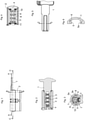
- the cylinder core 4 is rotatably mounted in the keyway of which the key 1 can be inserted in a known manner.
- two rows of core pins 3 arranged parallel to one another in the longitudinal direction are provided in the cylinder core 4, which are rotatably and axially displaceably mounted in bores of the cylinder core. They are based on springs 7, these springs sitting with one spring end in the franking in the core 4 and with the other spring end in the core pin. This controls the rotation of the pens so that the heads of the finger pens (see Fig figure 2 ) can create targeted at the lowest point of coding 5.6 in the key shank or when inserting the key shank in the keyway against the spring 7 are axially movable.
- the key shank is arched in the longitudinal direction, ie seen in cross section, the key shank forms a quarter or half arch (see Fig figure 6 ).
- the key channel formed in the cylinder core 4 and into which the key shank can be inserted is correspondingly congruent.
- the above-mentioned coding is formed on the inner contour of the key shank and consists - in the embodiment shown here - of two opposite coding planes 5 and 6, which run along or parallel to the longitudinal edges of the key shank.
- the heads of the core pins 3 interact with the coding, which consists of depressions and elevations, i.e. when the key shank is inserted into the keyway, the core pins are rotated about their longitudinal axis or axially displaced in the bore in the cylinder core, i.e. aligned in height.
- housing pins there are no housing pins that interact with the core pins.
- housing pins can also be used.
- the core pins 3 interact with the locking strips 8 arranged in the cylinder core 4 in a radially displaceable manner. Controlled by corresponding recesses 9 on the core pins 3, these locking bars are moved radially in a known manner in such a way that they - depending on the contact or contact of the pin 10 of the locking bar 8 on the core pins - are moved radially in the cylinder core, so that they are incorrectly coded can enter via the parting plane cylinder core / lock cylinder housing in a recess 12 in the lock cylinder housing 2 to prevent rotation of the cylinder core.
- the locking bar 8 or the locking bars - in the illustrated embodiment - are supported on both sides by springs 11 so that the core pins can move freely opposite.
Landscapes
- Lock And Its Accessories (AREA)
Abstract
Description
- Die Erfindung betrifft ein Schloss - Schlüssel - System, umfassend ein Schließzylindergehäuse mit einem drehbar darin gelagerten Zylinderkern in dessen Schlüsselkanal ein Schlüssel einführbar ist und durch eine Codierung am Schlüsselschaft ausrichtbare Kernstifte,, die mit einer radial verschiebbaren Sperrleiste zusammen wirken, die über die Trennebene Zylinderkern/Schließzylindergehäuse in eine Ausnehmung im Schließzylindergehäuse schiebbar ist, um bei unrichtiger Codierung des Schlüssels eine Drehung des Zylinderkerns - und damit die Ausführung eines Schließvorgangs - zu verhindern.
- Üblicherweise ist der Schlüsselschaft derartiger Flachschlüssel schlüsselbrustseitig mit Kerben versehen und weist beidseitg Profilierungen auf. Die Kerben und die Profilierung bilden zusammen eine Codierung, die für jeden Schlüssel typisch ist.
- Nachteilig ist, dass dieser Schlüsseltyp mittels herkömmlicher Kopiermaschinen einfach kopierbar ist, so dass deren Nachfertigung kaum Probleme bereitet.
- Aufgabe der Erfindung ist es, ein Schloss - Schlüssel - System vorzuschlagen, das einen besseren Kopierschutz bietet, d.h. dessen Nachfertigung erschwert ist
- Gelöst wird diese Aufgabe mit einem Schloss - Schlüssel - System, umfassend ein Schließzylindergehäuse mit einem drehbar darin gelagerten Zylinderkern in dessen Schlüsselkanal
- ein Schlüssel einführbar ist und durch eine Codierung am Schlüsselschaft ausrichtbare Kernstifte,, die mit einer radial verschiebbaren Sperrleiste zusammen wirken, die über die Trennebene Zylinderkern/Schließzylindergehäuse in eine Ausnehmung im Schließzylindergehäuse schiebbar
- ist, um bei unrichtiger Codierung des Schlüssels eine Drehung des Zylinderkerns - und damit die Ausführung eines Schließvorgangs - zu verhindern.,
- das dadurch gekennzeichnet ist,
- dass der Schlüsselschaft und entsprechend der Schlüsselkanal in Längsrichtung bogenförmig ausgebildet sind,
- dass die Codierung in der Innenkontur des Schlüsselschafts ausgebildet ist,
- dass die Kernstifte in Bohrungen im Zylinderkern federnd gelagert und derart positioniert sind,
- dass die Kernstifte beim Einführen des Schlüsselschafts in den Schlüsselkanal durch die Codierung am Schlüsselschaft um ihre Längsachse drehbar sind, um mit der Sperrleiste, deren radiale Verschiebung zulassend, in Eingriff zu kommen.
- Die erfindungsgemäß ausgebildete und angeordnete Codierung lässt sich mit herkömmlichen Kopiermaschinen nicht nachfertigen, sondern erfordert spezielle Werkzeuge, insbesondere Fräser.
- Die Erfindung soll nachfolgend mit Bezug auf die Zeichnungen näher erläutert werden.
- Dabei zeigt:
-
Fig. 1 eine Seitenansicht des Schließzylinders mit eingeführtem Schlüssel, -
Fig. 2 einen Längsschnitt gemäß A- A, -
Fig. 3 einen Querschnitt gemäß B - B, -
Fig. 4 einen Längsschnitt gemäß C - C, -
Fig. 5 eine Teilansicht des Schlüssels und -
Fig. 6 einen Querschnitt gemäß D - D - Im Schließzylinder 2 ist in bekannter Weise der Zylinderkern 4 drehbar gelagert in dessen Schlüsselkanal der Schlüssel 1 einführbar ist.
- Bei der hier dargestellten Ausführung sind im Zylinderkern 4 zwei parallel zueinander in Längsrichtung angeordnete Reihen mit Kernstiften 3 vorgesehen, die in Bohrungen des Zylinderkerns dreh- und axial verschiebbar gelagert sind. Sie stützen sich auf Federn 7 ab, wobei diese Federn mit einem Federende in der Freimachung im Kern 4 und mit dem anderen Federende im Kernstift sitzen. Dadurch wird die Drehbewegung der Stifte gesteuert, so dass sich die Köpfe der Fingerstifte (siehe
Figur 2 ) gezielt an den tiefsten Punkt der Codierung 5,6 im Schlüsselschaft anlegen können bzw. beim Einführen des Schlüsselschaftes in den Schlüsselkanal gegen die Feder 7 axial bewegbar sind. - Mit den Kernstiften 3 wirkt eine Codierung 5,6 zusammen, die sich in der Innenkontur des Schlüsselschaftes befindet (siehe
Figur 6 ). - Der Schlüsselschaft ist In Längsrichtung bogenförmig ausgebildet, d.h. im Querschnitt gesehen, bildet der Schlüsselschaft einen Viertel-oder Halbbogen (siehe
Figur 6 ). - Entsprechend kongruent ist der im Zylinderkern 4 ausgebildete Schlüsselkanal geformt in den der Schlüsselschaft einführbar ist.
- Die vorstehend erwähnte Codierung ist an der Innenkontur des Schlüsselschaftes ausgebildet und besteht - bei der hier gezeigten Ausführung - aus zwei sich gegenüber liegenden Codierebenen 5 und 6, die entlang oder parallel zu den Längskanten des Schlüsselschaftes verlaufen.
- Mit der Codierung, die aus Vertiefungen und Erhöhungen besteht, wirken die Köpfe der Kernstifte 3 zusammen, d.h. beim Einführen des Schlüsselschaftes in den Schlüsselkanal werden die Kernstifte um ihre Längsachse gedreht bzw. in der Bohrung in Zylinderkern axial verschoben, also in der Höhe ausgerichtet.
- Beim dargestellten Ausführungsbeispiel sind keine Gehäusestifte vorgesehen, die mit den Kernstiften zusammen wirken. Zusätzlich können jedoch auch Gehäusestifte Anwendung finden.
- Bei dem dargestellten Ausführungsbeispiel wirken die Kernstifte 3 mit im Zylinderkern 4 radial verschiebbar angeordneten Sperrleisten 8 zusammen. Durch entsprechende Ausnehmungen 9 an den Kernstiften 3 gesteuert, werden diese Sperrleisten in bekannter Weise derart radial verschoben, dass sie - je nach Berührung bzw. Anliegen der Zapfen 10 der Sperrleiste 8 an den Kernstiften - im Zylinderkern radial bewegt werden, sodass sie bei unrichtiger Codierung über die Trennebene Zylinderkern/Schließzylindergehäuse in eine Ausnehmung 12 im Schließzylindergehäuse 2 eintreten können , um eine Drehung des Zylinderkerns zu verhindern. Die Sperrleiste 8 bzw. die Sperrleisten - im dargestellten Ausführungsbeispiel - sind beidseitig durch Federn 11 abgestützt, so dass sich die Kernstifte frei gegenüber bewegen können.
Claims (9)
- Schloss - Schlüssel - System, umfassend ein Schließzylindergehäuse (2) mit einem drehbar darin gelagerten Zylinderkern (4) in dessen Schlüsselkanal ein Schlüssel (1) einführbar ist und durch eine Codierung (5,5a,6) am Schlüsselschaft ausrichtbare Kernstifte (3,3a), die mit einer radial verschiebbaren Sperrleiste (8) zusammen wirken, die über die Trennebene Zylinderkern/Schließzylindergehäuse in eine Ausnehmung (12) im Schließzylindergehäuse (2) schiebbar ist, um bei unrichtiger Codierung des Schlüssels eine Drehung des Zylinderkerns - und damit die Ausführung eines Schließvorgangs - zu verhindern,dadurch gekennzeichnet,dass der Schlüsselschaft und entsprechend der Schlüsselkanal in Längsrichtung bogenförmig ausgebildet sind,dass die Codierung (5,5a,6) in der Innenkontur des Schlüsselschafts ausgebildet ist,dass die Kernstifte (3,3a) in Bohrungen im Zylinderkern federnd gelagert und derart positioniert sind,dass die Kernstifte (3,3a) beim Einführen des Schlüsselschafts in den Schlüsselkanal durch die Codierung (5,5a,6) am Schlüsselschaft um ihre Längsachse drehbar sind, um mit der Sperrleiste (8), deren radiale Verschiebung zulassend, in Eingriff zu kommen.
- Schloss - Schlüssel - System nach Anspruch 1,
dadurch gekennzeichnet,
dass die Kernstifte axial verschiebbar sind. - Schloss - Schlüssel - System nach einem der vorstehenden Ansprüche,
dadurch gekennzeichnet,
dass die Kernstifte als Fingerstifte ausgebildet sind. - Schloss - Schlüssel - System nach Anspruch 1 bis 3,
dadurch gekennzeichnet,
dass der Schlüsselschaft und der Schlüsselkanal im Querschnitt gesehen als Viertel-oder Halbbogen ausgebildet sind. - Schloss - Schlüssel - System nach Anspruch 4,
dadurch gekennzeichnet,
dass die Codierung (5,5a,6) in der Innenkontur parallel zu und entlang mindestens einer der in Längsrichtung verlaufenden Schlüsselkanten ausgebildet ist. - Schloss - Schlüssel - System nach einem der vorstehenden Ansprüche,
dadurch gekennzeichnet,
dass das die Codierung (5,5a;6) in zwei übereinander liegenden Ebenen entlang der Schlüsselkanten ausgebildet ist. - Schloss - Schlüssel - System nach einem der vorstehenden Ansprüche,
dadurch gekennzeichnet,
dass die Codierung (5,6;5a) an beiden Längskanten der Innenkontur des Schlüsselschafts ausgebildet ist und dass entsprechend zwei Reihen von Kernstiften (3,3a) mit zwei verschiebbaren Sperrleisten (8) zusammenwirken. - Schloss - Schlüssel - System nach einem der vorstehenden Ansprüche,
dadurch gekennzeichnet,
dass die Kernstifte (3,3a) mit ihren zugeordneten Federn (7) drehfest verbunden sind. - Schloss - Schlüssel - System nach einem der vorstehenden Ansprüche,
dadurch gekennzeichnet,
dass die Kernstifte (3,3a) mehrere Ausnehmungen (9) für die Sperrleiste (8) aufweisen.
Applications Claiming Priority (1)
| Application Number | Priority Date | Filing Date | Title |
|---|---|---|---|
| DE102020124366.9A DE102020124366A1 (de) | 2020-09-18 | 2020-09-18 | Schloss-Schlüssel-System |
Publications (3)
| Publication Number | Publication Date |
|---|---|
| EP3971371A1 true EP3971371A1 (de) | 2022-03-23 |
| EP3971371B1 EP3971371B1 (de) | 2023-07-12 |
| EP3971371C0 EP3971371C0 (de) | 2023-07-12 |
Family
ID=78085765
Family Applications (1)
| Application Number | Title | Priority Date | Filing Date |
|---|---|---|---|
| EP21197676.6A Active EP3971371B1 (de) | 2020-09-18 | 2021-09-20 | Schloss-schlüssel-system |
Country Status (2)
| Country | Link |
|---|---|
| EP (1) | EP3971371B1 (de) |
| DE (1) | DE102020124366A1 (de) |
Citations (4)
| Publication number | Priority date | Publication date | Assignee | Title |
|---|---|---|---|---|
| US3499303A (en) * | 1968-04-17 | 1970-03-10 | Roy C Spain | Cylinder lock |
| DE102009026117A1 (de) * | 2009-07-07 | 2011-01-13 | C. Ed. Schulte Gesellschaft mit beschränkter Haftung Zylinderschloßfabrik | Schließzylinder mit passendem Schlüssel |
| US10472856B1 (en) * | 2018-10-18 | 2019-11-12 | Winloc Ag | Cylinder lock and key combination providing extra code combinations |
| US20200224454A1 (en) * | 2016-09-01 | 2020-07-16 | Urbanalps Ag | A key for controlling a lock with a cylindrical plug and a lock for validating this key |
Family Cites Families (2)
| Publication number | Priority date | Publication date | Assignee | Title |
|---|---|---|---|---|
| DE3021128C2 (de) | 1980-06-04 | 1987-02-12 | C. Ed. Schulte GmbH, 5628 Velbert | Zylinderschloß für Schließanlagen |
| AT407891B (de) | 1998-06-19 | 2001-07-25 | Evva Werke | Zylinderschloss mit zylindergehäuse und darin verdrehbarem zylinderkern |
-
2020
- 2020-09-18 DE DE102020124366.9A patent/DE102020124366A1/de not_active Ceased
-
2021
- 2021-09-20 EP EP21197676.6A patent/EP3971371B1/de active Active
Patent Citations (4)
| Publication number | Priority date | Publication date | Assignee | Title |
|---|---|---|---|---|
| US3499303A (en) * | 1968-04-17 | 1970-03-10 | Roy C Spain | Cylinder lock |
| DE102009026117A1 (de) * | 2009-07-07 | 2011-01-13 | C. Ed. Schulte Gesellschaft mit beschränkter Haftung Zylinderschloßfabrik | Schließzylinder mit passendem Schlüssel |
| US20200224454A1 (en) * | 2016-09-01 | 2020-07-16 | Urbanalps Ag | A key for controlling a lock with a cylindrical plug and a lock for validating this key |
| US10472856B1 (en) * | 2018-10-18 | 2019-11-12 | Winloc Ag | Cylinder lock and key combination providing extra code combinations |
Also Published As
| Publication number | Publication date |
|---|---|
| DE102020124366A1 (de) | 2022-03-24 |
| EP3971371B1 (de) | 2023-07-12 |
| EP3971371C0 (de) | 2023-07-12 |
Similar Documents
| Publication | Publication Date | Title |
|---|---|---|
| EP1055788B1 (de) | Flachschlüssel und Zylinderschloss | |
| DE8017685U1 (de) | Schliesszylinder mit passendem schluessel | |
| CH626680A5 (de) | ||
| DE19944070C2 (de) | Schließvorrichtung, insbesondere für Kraftfahrzeuge | |
| EP2454429A1 (de) | Schliessvorrichtung | |
| DE2627764C2 (de) | Zylinderschloß | |
| EP3092359B1 (de) | Zylinderschloss | |
| EP0712980B1 (de) | Zylinderschloss mit Zylinderkern und Zylindergehäuse | |
| DE10042070A1 (de) | Schloss-Schlüssel-System | |
| EP3872282B1 (de) | Schloss-schlüssel-system | |
| EP0814222B1 (de) | Flachschlüssel für Zylinderschloss | |
| EP3971371B1 (de) | Schloss-schlüssel-system | |
| AT403607B (de) | Schliesseinrichtung mit einem zylinderschloss und einem wendeflachschlüssel | |
| EP0911465B1 (de) | Flachschlüssel für Zylinderschlösser | |
| DE102022127486A1 (de) | Schließsystem bestehend aus einem Schließzylinder und einem passenden Schlüssel | |
| CH680935A5 (de) | ||
| EP1437462B1 (de) | System mit einem Schlüssel und mit einem Sicherheitsschloss | |
| DE202006003869U1 (de) | Zylinderschloss und Flachschlüssel | |
| AT390990B (de) | Zylinderschloss sowie schluessel dafuer | |
| AT372472B (de) | Zylinderschloss und schluessel, schluessel fuer das zylinderschloss und verfahren zur herstellung des schluessels | |
| AT406884B (de) | Schliesszylinder | |
| DE19610182A1 (de) | Zylinderschloß mit mechanischer Doppelcodierung | |
| AT523310A1 (de) | Zylinderschloss | |
| EP4321714A1 (de) | Schliesssystem bestehend aus einem schliesszylinder und einem passenden schlüssel | |
| DE2546550A1 (de) | Schliesszylinder fuer flachschluessel |
Legal Events
| Date | Code | Title | Description |
|---|---|---|---|
| PUAI | Public reference made under article 153(3) epc to a published international application that has entered the european phase |
Free format text: ORIGINAL CODE: 0009012 |
|
| STAA | Information on the status of an ep patent application or granted ep patent |
Free format text: STATUS: THE APPLICATION HAS BEEN PUBLISHED |
|
| AK | Designated contracting states |
Kind code of ref document: A1 Designated state(s): AL AT BE BG CH CY CZ DE DK EE ES FI FR GB GR HR HU IE IS IT LI LT LU LV MC MK MT NL NO PL PT RO RS SE SI SK SM TR |
|
| STAA | Information on the status of an ep patent application or granted ep patent |
Free format text: STATUS: REQUEST FOR EXAMINATION WAS MADE |
|
| RIN1 | Information on inventor provided before grant (corrected) |
Inventor name: MATSCHKE, STEFFEN |
|
| 17P | Request for examination filed |
Effective date: 20220920 |
|
| RBV | Designated contracting states (corrected) |
Designated state(s): AL AT BE BG CH CY CZ DE DK EE ES FI FR GB GR HR HU IE IS IT LI LT LU LV MC MK MT NL NO PL PT RO RS SE SI SK SM TR |
|
| RIC1 | Information provided on ipc code assigned before grant |
Ipc: E05B 19/00 20060101ALI20221207BHEP Ipc: E05B 27/00 20060101AFI20221207BHEP |
|
| GRAP | Despatch of communication of intention to grant a patent |
Free format text: ORIGINAL CODE: EPIDOSNIGR1 |
|
| STAA | Information on the status of an ep patent application or granted ep patent |
Free format text: STATUS: GRANT OF PATENT IS INTENDED |
|
| INTG | Intention to grant announced |
Effective date: 20230207 |
|
| GRAS | Grant fee paid |
Free format text: ORIGINAL CODE: EPIDOSNIGR3 |
|
| GRAA | (expected) grant |
Free format text: ORIGINAL CODE: 0009210 |
|
| STAA | Information on the status of an ep patent application or granted ep patent |
Free format text: STATUS: THE PATENT HAS BEEN GRANTED |
|
| AK | Designated contracting states |
Kind code of ref document: B1 Designated state(s): AL AT BE BG CH CY CZ DE DK EE ES FI FR GB GR HR HU IE IS IT LI LT LU LV MC MK MT NL NO PL PT RO RS SE SI SK SM TR |
|
| REG | Reference to a national code |
Ref country code: CH Ref legal event code: EP |
|
| REG | Reference to a national code |
Ref country code: IE Ref legal event code: FG4D Free format text: LANGUAGE OF EP DOCUMENT: GERMAN |
|
| REG | Reference to a national code |
Ref country code: DE Ref legal event code: R096 Ref document number: 502021000997 Country of ref document: DE |
|
| U01 | Request for unitary effect filed |
Effective date: 20230728 |
|
| U07 | Unitary effect registered |
Designated state(s): AT BE BG DE DK EE FI FR IT LT LU LV MT NL PT SE SI Effective date: 20230803 |
|
| U20 | Renewal fee for the european patent with unitary effect paid |
Year of fee payment: 3 Effective date: 20230818 |
|
| REG | Reference to a national code |
Ref country code: LT Ref legal event code: MG9D |
|
| PG25 | Lapsed in a contracting state [announced via postgrant information from national office to epo] |
Ref country code: GR Free format text: LAPSE BECAUSE OF FAILURE TO SUBMIT A TRANSLATION OF THE DESCRIPTION OR TO PAY THE FEE WITHIN THE PRESCRIBED TIME-LIMIT Effective date: 20231013 |
|
| PG25 | Lapsed in a contracting state [announced via postgrant information from national office to epo] |
Ref country code: ES Free format text: LAPSE BECAUSE OF FAILURE TO SUBMIT A TRANSLATION OF THE DESCRIPTION OR TO PAY THE FEE WITHIN THE PRESCRIBED TIME-LIMIT Effective date: 20230712 |
|
| PG25 | Lapsed in a contracting state [announced via postgrant information from national office to epo] |
Ref country code: IS Free format text: LAPSE BECAUSE OF FAILURE TO SUBMIT A TRANSLATION OF THE DESCRIPTION OR TO PAY THE FEE WITHIN THE PRESCRIBED TIME-LIMIT Effective date: 20231112 |
|
| PG25 | Lapsed in a contracting state [announced via postgrant information from national office to epo] |
Ref country code: RS Free format text: LAPSE BECAUSE OF FAILURE TO SUBMIT A TRANSLATION OF THE DESCRIPTION OR TO PAY THE FEE WITHIN THE PRESCRIBED TIME-LIMIT Effective date: 20230712 Ref country code: NO Free format text: LAPSE BECAUSE OF FAILURE TO SUBMIT A TRANSLATION OF THE DESCRIPTION OR TO PAY THE FEE WITHIN THE PRESCRIBED TIME-LIMIT Effective date: 20231012 Ref country code: IS Free format text: LAPSE BECAUSE OF FAILURE TO SUBMIT A TRANSLATION OF THE DESCRIPTION OR TO PAY THE FEE WITHIN THE PRESCRIBED TIME-LIMIT Effective date: 20231112 Ref country code: HR Free format text: LAPSE BECAUSE OF FAILURE TO SUBMIT A TRANSLATION OF THE DESCRIPTION OR TO PAY THE FEE WITHIN THE PRESCRIBED TIME-LIMIT Effective date: 20230712 Ref country code: GR Free format text: LAPSE BECAUSE OF FAILURE TO SUBMIT A TRANSLATION OF THE DESCRIPTION OR TO PAY THE FEE WITHIN THE PRESCRIBED TIME-LIMIT Effective date: 20231013 Ref country code: ES Free format text: LAPSE BECAUSE OF FAILURE TO SUBMIT A TRANSLATION OF THE DESCRIPTION OR TO PAY THE FEE WITHIN THE PRESCRIBED TIME-LIMIT Effective date: 20230712 |
|
| PG25 | Lapsed in a contracting state [announced via postgrant information from national office to epo] |
Ref country code: PL Free format text: LAPSE BECAUSE OF FAILURE TO SUBMIT A TRANSLATION OF THE DESCRIPTION OR TO PAY THE FEE WITHIN THE PRESCRIBED TIME-LIMIT Effective date: 20230712 |
|
| REG | Reference to a national code |
Ref country code: DE Ref legal event code: R097 Ref document number: 502021000997 Country of ref document: DE |
|
| PG25 | Lapsed in a contracting state [announced via postgrant information from national office to epo] |
Ref country code: SM Free format text: LAPSE BECAUSE OF FAILURE TO SUBMIT A TRANSLATION OF THE DESCRIPTION OR TO PAY THE FEE WITHIN THE PRESCRIBED TIME-LIMIT Effective date: 20230712 Ref country code: RO Free format text: LAPSE BECAUSE OF FAILURE TO SUBMIT A TRANSLATION OF THE DESCRIPTION OR TO PAY THE FEE WITHIN THE PRESCRIBED TIME-LIMIT Effective date: 20230712 Ref country code: CZ Free format text: LAPSE BECAUSE OF FAILURE TO SUBMIT A TRANSLATION OF THE DESCRIPTION OR TO PAY THE FEE WITHIN THE PRESCRIBED TIME-LIMIT Effective date: 20230712 Ref country code: SK Free format text: LAPSE BECAUSE OF FAILURE TO SUBMIT A TRANSLATION OF THE DESCRIPTION OR TO PAY THE FEE WITHIN THE PRESCRIBED TIME-LIMIT Effective date: 20230712 |
|
| PLBE | No opposition filed within time limit |
Free format text: ORIGINAL CODE: 0009261 |
|
| STAA | Information on the status of an ep patent application or granted ep patent |
Free format text: STATUS: NO OPPOSITION FILED WITHIN TIME LIMIT |
|
| PG25 | Lapsed in a contracting state [announced via postgrant information from national office to epo] |
Ref country code: MC Free format text: LAPSE BECAUSE OF FAILURE TO SUBMIT A TRANSLATION OF THE DESCRIPTION OR TO PAY THE FEE WITHIN THE PRESCRIBED TIME-LIMIT Effective date: 20230712 |
|
| 26N | No opposition filed |
Effective date: 20240415 |
|
| REG | Reference to a national code |
Ref country code: IE Ref legal event code: MM4A |
|
| PG25 | Lapsed in a contracting state [announced via postgrant information from national office to epo] |
Ref country code: IE Free format text: LAPSE BECAUSE OF NON-PAYMENT OF DUE FEES Effective date: 20230920 |
|
| PG25 | Lapsed in a contracting state [announced via postgrant information from national office to epo] |
Ref country code: IE Free format text: LAPSE BECAUSE OF NON-PAYMENT OF DUE FEES Effective date: 20230920 |
|
| U20 | Renewal fee for the european patent with unitary effect paid |
Year of fee payment: 4 Effective date: 20240822 |
|
| PG25 | Lapsed in a contracting state [announced via postgrant information from national office to epo] |
Ref country code: CY Free format text: LAPSE BECAUSE OF FAILURE TO SUBMIT A TRANSLATION OF THE DESCRIPTION OR TO PAY THE FEE WITHIN THE PRESCRIBED TIME-LIMIT; INVALID AB INITIO Effective date: 20210920 |
|
| PG25 | Lapsed in a contracting state [announced via postgrant information from national office to epo] |
Ref country code: HU Free format text: LAPSE BECAUSE OF FAILURE TO SUBMIT A TRANSLATION OF THE DESCRIPTION OR TO PAY THE FEE WITHIN THE PRESCRIBED TIME-LIMIT; INVALID AB INITIO Effective date: 20210920 |
|
| U20 | Renewal fee for the european patent with unitary effect paid |
Year of fee payment: 5 Effective date: 20250821 |
|
| REG | Reference to a national code |
Ref country code: CH Ref legal event code: U11 Free format text: ST27 STATUS EVENT CODE: U-0-0-U10-U11 (AS PROVIDED BY THE NATIONAL OFFICE) Effective date: 20251001 |
|
| PG25 | Lapsed in a contracting state [announced via postgrant information from national office to epo] |
Ref country code: TR Free format text: LAPSE BECAUSE OF FAILURE TO SUBMIT A TRANSLATION OF THE DESCRIPTION OR TO PAY THE FEE WITHIN THE PRESCRIBED TIME-LIMIT Effective date: 20230712 |
|
| PGFP | Annual fee paid to national office [announced via postgrant information from national office to epo] |
Ref country code: CH Payment date: 20251001 Year of fee payment: 5 |
|
| GBPC | Gb: european patent ceased through non-payment of renewal fee |
Effective date: 20250920 |
|
| PG25 | Lapsed in a contracting state [announced via postgrant information from national office to epo] |
Ref country code: GB Free format text: LAPSE BECAUSE OF NON-PAYMENT OF DUE FEES Effective date: 20250920 |