EP3971361A1 - Disque mural en argile - Google Patents
Disque mural en argile Download PDFInfo
- Publication number
- EP3971361A1 EP3971361A1 EP21196101.6A EP21196101A EP3971361A1 EP 3971361 A1 EP3971361 A1 EP 3971361A1 EP 21196101 A EP21196101 A EP 21196101A EP 3971361 A1 EP3971361 A1 EP 3971361A1
- Authority
- EP
- European Patent Office
- Prior art keywords
- clay
- wooden
- wooden slats
- wall panel
- panel
- Prior art date
- Legal status (The legal status is an assumption and is not a legal conclusion. Google has not performed a legal analysis and makes no representation as to the accuracy of the status listed.)
- Granted
Links
- 239000004927 clay Substances 0.000 claims abstract description 131
- 238000010276 construction Methods 0.000 claims abstract description 17
- 241000826860 Trapezium Species 0.000 claims description 15
- 239000000853 adhesive Substances 0.000 claims description 9
- 230000001070 adhesive effect Effects 0.000 claims description 9
- 239000000945 filler Substances 0.000 claims description 2
- 239000000463 material Substances 0.000 description 6
- 239000011449 brick Substances 0.000 description 5
- 238000011161 development Methods 0.000 description 5
- 230000018109 developmental process Effects 0.000 description 5
- 238000009413 insulation Methods 0.000 description 5
- 238000004519 manufacturing process Methods 0.000 description 5
- 230000000694 effects Effects 0.000 description 4
- 239000004566 building material Substances 0.000 description 3
- 239000010410 layer Substances 0.000 description 3
- 239000004575 stone Substances 0.000 description 3
- 229920002522 Wood fibre Polymers 0.000 description 2
- 229920001222 biopolymer Polymers 0.000 description 2
- 239000011506 clay plaster Substances 0.000 description 2
- 229920005610 lignin Polymers 0.000 description 2
- 239000003973 paint Substances 0.000 description 2
- 238000012545 processing Methods 0.000 description 2
- 230000003068 static effect Effects 0.000 description 2
- 239000003351 stiffener Substances 0.000 description 2
- 239000002025 wood fiber Substances 0.000 description 2
- 241001669679 Eleotris Species 0.000 description 1
- 239000000654 additive Substances 0.000 description 1
- 238000005253 cladding Methods 0.000 description 1
- 230000001419 dependent effect Effects 0.000 description 1
- 238000013461 design Methods 0.000 description 1
- 239000000428 dust Substances 0.000 description 1
- 239000003344 environmental pollutant Substances 0.000 description 1
- 239000004744 fabric Substances 0.000 description 1
- 239000000835 fiber Substances 0.000 description 1
- 238000005338 heat storage Methods 0.000 description 1
- 238000003780 insertion Methods 0.000 description 1
- 230000037431 insertion Effects 0.000 description 1
- 238000000034 method Methods 0.000 description 1
- 235000019645 odor Nutrition 0.000 description 1
- 238000005192 partition Methods 0.000 description 1
- 231100000719 pollutant Toxicity 0.000 description 1
- 238000009417 prefabrication Methods 0.000 description 1
- 239000002994 raw material Substances 0.000 description 1
- 239000002356 single layer Substances 0.000 description 1
- 238000001179 sorption measurement Methods 0.000 description 1
- 238000012360 testing method Methods 0.000 description 1
- 238000012546 transfer Methods 0.000 description 1
- 239000010876 untreated wood Substances 0.000 description 1
- 239000002023 wood Substances 0.000 description 1
Images


Classifications
-
- E—FIXED CONSTRUCTIONS
- E04—BUILDING
- E04C—STRUCTURAL ELEMENTS; BUILDING MATERIALS
- E04C2/00—Building elements of relatively thin form for the construction of parts of buildings, e.g. sheet materials, slabs, or panels
- E04C2/30—Building elements of relatively thin form for the construction of parts of buildings, e.g. sheet materials, slabs, or panels characterised by the shape or structure
- E04C2/38—Building elements of relatively thin form for the construction of parts of buildings, e.g. sheet materials, slabs, or panels characterised by the shape or structure with attached ribs, flanges, or the like, e.g. framed panels
- E04C2/386—Building elements of relatively thin form for the construction of parts of buildings, e.g. sheet materials, slabs, or panels characterised by the shape or structure with attached ribs, flanges, or the like, e.g. framed panels with a frame of unreconstituted or laminated wood
-
- E—FIXED CONSTRUCTIONS
- E04—BUILDING
- E04C—STRUCTURAL ELEMENTS; BUILDING MATERIALS
- E04C2/00—Building elements of relatively thin form for the construction of parts of buildings, e.g. sheet materials, slabs, or panels
- E04C2/30—Building elements of relatively thin form for the construction of parts of buildings, e.g. sheet materials, slabs, or panels characterised by the shape or structure
- E04C2/42—Gratings; Grid-like panels
- E04C2/421—Gratings; Grid-like panels made of bar-like elements, e.g. bars discontinuous in one direction
- E04C2/422—Gratings; Grid-like panels made of bar-like elements, e.g. bars discontinuous in one direction with continuous bars connecting at crossing points of the grid pattern
- E04C2/423—Gratings; Grid-like panels made of bar-like elements, e.g. bars discontinuous in one direction with continuous bars connecting at crossing points of the grid pattern with notches
Definitions
- the invention relates to a loam wall panel with a flat wooden frame made of a plurality of wooden slats crossing one another and connected to one another at the crossing points and a plurality of loam components arranged between the wooden slats.
- Clay has been used to build houses around the world for thousands of years. Especially in Central and Northern Europe there is a long earth building tradition in which earth components either take on load-bearing functions, e.g. walls in adobe masonry construction, rammed earth construction or corrugated construction, or are used in a space-enclosing function, e.g or non-supporting interior walls.
- load-bearing functions e.g. walls in adobe masonry construction, rammed earth construction or corrugated construction
- space-enclosing function e.g or non-supporting interior walls.
- clay as a building material in Europe was largely replaced by other industrially manufactured building materials and with it the knowledge of the material and the craftsmanship involved in processing it.
- clay has been rediscovered in architecture due to its extremely low primary energy requirements and its good material properties.
- clay its sustainability as a building material made from renewable raw materials with good regional availability, its recyclability and its very good building physics, building biology and indoor climate properties. Due to its sorption capacity, clay balances the air humidity, also absorbs pollutants and odors and, depending on the material thickness, has comparatively good heat-storing, soundproofing and acoustic properties.
- Clay plasters and clay paints The largest areas of application for clay in construction are currently clay plasters and clay paints. Clay paints and clay finishing plasters up to 3 mm thick cannot usually exploit the special properties of clay, such as heat storage and humidity regulation, due to their small thickness.
- the product "clay building board” was launched on the market in recent years.
- Clay building boards are made from construction earth and usually contain additives from aggregates, brick dust, expanded clay, plant parts or fibers or crushed chemically untreated wood in order to reduce the weight of the boards and to stabilize the board in its structure.
- Clay panels can Reinforced at the core or close to the surface with bars, mats, grids or fabrics.
- clay drywall panels are used in interior design, for example for planking or cladding interior walls, such as post constructions or suitable flat substructures. They combine clay plaster and building board in one product and only have to be smoothed over, usually with clay plaster, to achieve a finished surface.
- clay building boards cannot absorb a statically stiffening effect.
- the Technical Data Sheet TM 075 regulates under 4.1 that clay panels are not used to reinforce components, e.g. walls, partitions, roof trusses, etc. A test of the modulus of elasticity and the shear strength (bearing failure) can therefore be omitted and there are no minimum requirements. Therefore, when walls are used with a required stiffening effect, an additional substructure is always required, e.g. made of wood-based panels, to which the clay building panels are then additionally attached.
- the disadvantage of these construction methods is that the wall or wall panel in the timber construction using clay does not take into account the performance of the two materials (static and building physics) in an integrated manner.
- a wooden stud wall with several wooden studs arranged at a distance from one another and a wall lining of the fields between the wooden studs 1 consisting of molded bricks is known.
- Each wooden stand has a vertical retaining strip on its side facing the adjacent field, which can be designed as a triangular strip and nailed to the associated wooden stand.
- the bricks forming the lining are preferably clay bricks or clay bricks.
- Each shaped stone which is designed, for example, as a shaped clay stone or as a shaped clay stone, extends over the entire width of the field between the spaced-apart wooden posts 1.
- the DE 42 15 081 A1 describes an earth building wall element and a method for its production.
- the adobe wall element has a supporting frame and a light-weight loam filling that at least partially embeds it.
- the support frame has a stiffener and at least two parallel uprights of equal length, which are arranged at the greatest possible distance from one another, crossing one another via the stiffener are connected in a pressure and tensile manner and each have dowel holes at their ends, which are arranged in a predetermined grid spacing.
- the filling has a circumferential groove, which is made up of an upper groove for accommodating a frame, a lower groove for accommodating a sleeper and side grooves of the same construction. The ends of the uprights protrude slightly from the bottom of the upper and lower grooves, so that the filling has no load-bearing function.
- a clay building wall panel is thus provided with a flat wooden frame made of a plurality of wooden slats crossing one another and connected to one another at the crossing points and a plurality of clay components arranged between the wooden slats, the clay components being designed as flat prefabricated clay components which are inserted between the wooden slats in this way that they rest with their edge surfaces facing the wooden slats at least in sections flat against the wooden slats surrounding them.
- the earthen wall panel according to the invention is flat in its reference state and can be loaded by forces in its plane.
- Such surface structures are called disks in technical mechanics.
- a flat component In structural engineering, a flat component is said to have a disc effect if it is able to absorb and safely dissipate forces acting in the direction of its plane to a certain extent without being excessively deformed or destroyed by the resulting internal shear stresses.
- the fact that the wooden framework is level does not mean that the wooden slats can also have different cross-sections, thicknesses and/or widths. Alternatively it can be provided that all wooden slats have the same cross-sectional shape.
- the flat prefabricated clay components therefore each have front and rear sides which are parallel to the front and rear sides of the entire clay wall pane. Edge surfaces are the surfaces that connect the front and back sides and are therefore at a non-zero angle to the front and back sides of the entire clay wall pane. Even if the clay components used in conventional buildings do not have a load-dissipating function, it has been shown within the scope of the present invention that the insertion of the planar prefabricated clay components between the wooden slats in such a way that they lie flat against the surrounding wooden slats with their edge surfaces facing the wooden slats, leads to additional bracing and improved load transfer of the entire clay wall panel.
- the wooden slats can have any cross-section. According to a preferred embodiment, they have a rectangular cross section.
- the prefabricated clay components then also have a rectangular cross-section so that they can be inserted between the wooden slats in such a way that their edge surfaces can lie flat against the edge surfaces of the wooden slats
- an earthen wall panel is provided that can be designed to be stiffening and load-bearing and, moreover, also fireproof.
- the invention thus provides a clay wall panel with a stiffening effect for timber panel construction. It can be used as a stiffening element and represents an alternative to OSB panels.
- the clay wall panel has a wooden lattice structure made from a number of wooden slats that cross one another and are connected to one another at the crossing points.
- the meshes of the lattice structure are filled with prefabricated clay parts.
- the finish can be a single or multiple layer, preferably offset, laid clay building board as a cover board.
- the wooden slats can have different cross-sections.
- the wooden slats have the shape of a trapezium, preferably an isosceles trapezium, in cross section in a plane perpendicular to the longitudinal direction of the wooden slats, with the front sides and the back sides of these wooden slats being the base sides of the trapezium form.
- the longitudinal direction of the wooden slats means the direction of their long extension.
- the prefabricated clay components have the shape of a rectangle and, in cross section in a plane perpendicular to one side of the rectangle, have the shape of a trapezium, preferably an isosceles trapezium, with the The fronts and backs of these prefabricated clay components form the base of the trapezium.
- the prefabricated clay components can be inserted between the wooden slats in a simple and safe manner without the risk of them slipping through the gaps between the wooden slats.
- the wooden frame is surrounded by a wooden frame serving as a bearing for the wooden frame.
- the earthen wall panel can already be supplied with such a load-bearing frame.
- Part of such a frame can be the floor or the ceiling of a building.
- the wooden slats are attached to each other at the points where the wooden slats cross each other by means of screws and/or nails and/or staples and/or wooden pins and/or an adhesive attachment, e.g. by means of a lignin adhesive bond (adhesive with a natural biopolymer). are.
- the crossing points of the wooden slats can be designed differently. Preferably, however, that at least some of the wooden slats, preferably all of the wooden slats, are notched in the areas where the wooden slats cross each other, preferably in such a way that the front and back sides of the wooden slats each have a single form a common flat surface. In this way, planar surfaces of the wooden framework can be achieved.
- the clay wall panel is ready for use when it is fitted with the wooden framework and the prefabricated clay components.
- at least one clay building board is placed on the front and/or rear of the structure made of the wooden frame made of the interconnected wooden slats and the prefabricated clay components inserted between the wooden slats.
- the clay building wall pane preferably closes completely at the front and/or rear with one clay building panel or several clay building panels.
- the clay building board is held by means of fastening means on wooden slats of the wooden framework, the fastening means are countersunk in the clay building board and the area above the fastening means is filled with a filler up to the surface of the clay building board.
- the fastening means is countersunk by at least 5 mm.
- Such a filling material can be clay, for example. This configuration can be helpful for fire protection, since in this way, particularly if the fastening means is a screw or a nail, the heat input into the earthen wall pane can be reduced in the event of a fire.
- the prefabricated clay components preferably have a maximum extension of 50 cm, more preferably 40 cm and very particularly preferably 30 cm.
- the thickness of the prefabricated clay components is preferably between 15 mm and 45 mm, more preferably between 18 and 35 mm and very particularly preferably between 20 and 30 mm.
- the invention also relates to the use of a clay wall panel, as described above, for timber panel construction.
- the clay wall panel is preferably used to stiffen a wooden panel wall.
- clay wall panel 1 according to a preferred embodiment of the invention based on its production with reference to Figures 1a to 1h described.
- a simple manufacturing method is provided here. Only the machines that are part of the standard equipment of carpentry companies are used. This means that processing companies do not incur high acquisition costs for complex, CNC-controlled machines.
- the material for the cross-sections used for the wooden frame 2 is based on commercially available wooden slats, which are available in the formats 24 mm x 48 mm, 30 mm x 50 mm and 40 mm x 60 mm. Depending on the requirement profile, the cross-sections can be varied or adjusted.
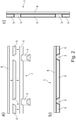
- the Figures 1a to 1h serve to illustrate the principle of a clay wall panel 1 according to a preferred embodiment of the invention.
- the structural assembly of the clay wall panel 1 can be seen in the sequence.
- FIG. 1a how out Figure 1a
- two types of wooden slats 3 are used for the wooden framework 2, namely on the one hand wooden slats 3 which have a rectangular cross section and are provided with notches 10.
- the shape of these notches 10 corresponds to the cross section of second wooden slats 3, which are trapezoidal in cross section, so that they can be received in the notches 10 with a positive fit.
- Figure 1b By assembling these wooden slats 3 results, as shown schematically Figure 1b visible, a flat wooden framework 2.
- present adhesive fasteners 4 are used, which are introduced in the areas of the notches 10, namely lignin adhesive bonds based on an adhesive with a natural biopolymer.
- the end Figure 1c it can now be seen how clay components in the form of planar prefabricated clay components 5 are inserted from above into the openings formed between the wooden slats 3 .
- the rule here is that the prefabricated clay components 5 have the shape of a rectangle and, in a cross-section in a plane perpendicular to one side of the rectangle, the shape of a trapezium, namely an isosceles trapezium, with the front sides and rear sides of these prefabricated clay components 5 forming the base sides of the trapezium.
- the prefabricated clay components 5 In this way it is possible to insert the prefabricated clay components 5 into the openings between the wooden slats 3 in such a way that they cannot slip through these openings.
- clay building boards 8 are used on the prefabricated clay components 5 and between the notched wooden slats.
- the clay building wall disc 1 with clay building panels 8 used in this way is out Figure 1f evident.
- Figure 1d shown placed on the entire structure a larger clay building board 8, which closes the clay building wall disc 1 here at the top.
- the finished clay building wall panel 1 according to the preferred exemplary embodiment of the invention described here is made Figure 1h evident.
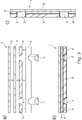
- two different variants of a clay wall panel 1 are shown with a basic section. These two variants meet different static requirements.
- the wooden framework 2 exclusively of wooden slats 3 with the dimensions 24 mm ⁇ 48 mm.
- the junctions are joined by overlapping, as a result of which the wooden slats 3 running in the transverse or longitudinal direction are then at the same height.
- the principle section shows the parallel 30° chamfer cut for accommodating the prefabricated clay component 5.
- a commercially available clay building board 8 with a thickness of 16 mm forms the end of the clay building wall panel 1 on the inside of the room.
- the layer thickness of the clay is at least 40 mm.
- the wooden framework 2 consists of wooden slats 3 with dimensions of 24 mm ⁇ 48 mm or 40 mm ⁇ 60 mm. The junctions are joined by a notch in the higher wooden slat 3.
- the wooden slat 3 with the dimensions 24 mm ⁇ 48 mm has a 30° bevel cut, runs through and is fastened at the junction with a fastener such as a screw or nail , fixed.
- the resulting height difference is compensated for with an additional 16 mm thick clay building board 8.
- a commercially available clay building panel 8 with a thickness of 16 mm forms the end of the clay building wall panel 1 on the inside of the room.
- the layer thickness of the clay is at least 56 mm.
- the visible system sketches show preferred fields of application for the clay wall panel 1.
- the clay wall panel 1 can be used as paneling on both sides for an inner wall 12, as in Figure 4a shown, or used as one-sided planking on the inside of the room for an outer wall 13, as in Figure 4b shown. In both cases, two or one clay wall panel 1 is used, as with reference to FIG Figures 2a to 2c described.
- the construction shown has the inner wall 13 on both sides of a corresponding earthen wall panel 1.
- This clay building wall discs 1 are applied to a wooden framework 14 made of wooden slats with dimensions of 40 mm x 60 mm, which is provided with an insulation 11.
- the outer wall 13 shown is fitted on the inside with a corresponding clay wall panel 1 on a significantly stronger wooden framework 16 for the wooden panel construction, which is also provided with insulation 11 .
- a wood fiber insulation board 15 forms the end of the outer wall 13 on the outside. Both the inner wall 12 and the outer wall 13 can be plastered and/or painted as required.
Landscapes
- Engineering & Computer Science (AREA)
- Architecture (AREA)
- Civil Engineering (AREA)
- Structural Engineering (AREA)
- Finishing Walls (AREA)
Applications Claiming Priority (1)
| Application Number | Priority Date | Filing Date | Title |
|---|---|---|---|
| DE102020123773.1A DE102020123773A1 (de) | 2020-09-11 | 2020-09-11 | Lehmbauwandscheibe |
Publications (3)
| Publication Number | Publication Date |
|---|---|
| EP3971361A1 true EP3971361A1 (fr) | 2022-03-23 |
| EP3971361C0 EP3971361C0 (fr) | 2024-07-10 |
| EP3971361B1 EP3971361B1 (fr) | 2024-07-10 |
Family
ID=78049137
Family Applications (1)
| Application Number | Title | Priority Date | Filing Date |
|---|---|---|---|
| EP21196101.6A Active EP3971361B1 (fr) | 2020-09-11 | 2021-09-10 | Panneau mural en argile |
Country Status (2)
| Country | Link |
|---|---|
| EP (1) | EP3971361B1 (fr) |
| DE (1) | DE102020123773A1 (fr) |
Cited By (1)
| Publication number | Priority date | Publication date | Assignee | Title |
|---|---|---|---|---|
| CN115745569A (zh) * | 2022-12-03 | 2023-03-07 | 深圳市特区建工固废资源化有限公司 | 一种建筑废弃物制备烧结墙板的方法 |
Citations (5)
| Publication number | Priority date | Publication date | Assignee | Title |
|---|---|---|---|---|
| DE3545707A1 (de) * | 1985-12-21 | 1987-06-25 | Siegfried Gebert | Leichtlehmbauelement |
| DE4215081A1 (de) | 1992-05-07 | 1993-11-11 | Peter Breidenbach | Lehmbau-Wandelement und Verfahren zu seiner Herstellung |
| DE4422605A1 (de) * | 1994-06-28 | 1996-01-04 | Fuchs Holzbau Gmbh | Aufbau einer zumindest teilweise vorgefertigten Wand für ein Haus, insbesondere Wohnhaus |
| DE19951231A1 (de) * | 1999-10-25 | 2001-04-26 | Leon Pytlik | Wandelement in Skelettbauweise |
| DE102005033834A1 (de) | 2005-07-20 | 2007-03-15 | Philipp Liebig | Holzständerwand |
Family Cites Families (1)
| Publication number | Priority date | Publication date | Assignee | Title |
|---|---|---|---|---|
| DE19833559A1 (de) | 1998-07-25 | 2000-02-10 | Stefan Nothegger | Zwei- oder mehrwandige Konstruktion für Wände, Decken oder Dächer |
-
2020
- 2020-09-11 DE DE102020123773.1A patent/DE102020123773A1/de active Pending
-
2021
- 2021-09-10 EP EP21196101.6A patent/EP3971361B1/fr active Active
Patent Citations (5)
| Publication number | Priority date | Publication date | Assignee | Title |
|---|---|---|---|---|
| DE3545707A1 (de) * | 1985-12-21 | 1987-06-25 | Siegfried Gebert | Leichtlehmbauelement |
| DE4215081A1 (de) | 1992-05-07 | 1993-11-11 | Peter Breidenbach | Lehmbau-Wandelement und Verfahren zu seiner Herstellung |
| DE4422605A1 (de) * | 1994-06-28 | 1996-01-04 | Fuchs Holzbau Gmbh | Aufbau einer zumindest teilweise vorgefertigten Wand für ein Haus, insbesondere Wohnhaus |
| DE19951231A1 (de) * | 1999-10-25 | 2001-04-26 | Leon Pytlik | Wandelement in Skelettbauweise |
| DE102005033834A1 (de) | 2005-07-20 | 2007-03-15 | Philipp Liebig | Holzständerwand |
Cited By (1)
| Publication number | Priority date | Publication date | Assignee | Title |
|---|---|---|---|---|
| CN115745569A (zh) * | 2022-12-03 | 2023-03-07 | 深圳市特区建工固废资源化有限公司 | 一种建筑废弃物制备烧结墙板的方法 |
Also Published As
| Publication number | Publication date |
|---|---|
| EP3971361C0 (fr) | 2024-07-10 |
| DE102020123773A1 (de) | 2022-03-17 |
| EP3971361B1 (fr) | 2024-07-10 |
Similar Documents
| Publication | Publication Date | Title |
|---|---|---|
| EP1097032B1 (fr) | Element en bois stratifie prefabrique | |
| EP1808538A2 (fr) | Construction faite de pièces individuelles | |
| WO1998044212A1 (fr) | Panneau isolant composite autoporteur et son procede de fabrication | |
| EP3971361B1 (fr) | Panneau mural en argile | |
| DE4413953A1 (de) | Wand-, Decken-, oder Dachelement für Gebäude in Tafelbauart | |
| EP3543416B1 (fr) | Élément de plafond bois-béton | |
| CH701370A2 (de) | Verfahren zur Herstellung von Holz-Strukturelementen, ein Holz-Strukturelement und Lamellenelement. | |
| DE20009571U1 (de) | Tafelförmiges Holzverbundelement | |
| WO2021170530A1 (fr) | Composant de panneau en bois, procédé de fabrication d'un composant de panneau en bois et utilisation d'un composant de panneau en bois | |
| EP1995387B1 (fr) | Composant en bois et élément mural formé à l'aide de celui-ci | |
| WO2007079739A2 (fr) | Ouvrage constitué de parties individuelles | |
| EP3779084B1 (fr) | Élément de panneau en bois et utilisation de panneaux décoratifs | |
| DE102017111975A1 (de) | Modulares Holzbauelement geeignet zum Ausbilden von Wandelementen für Gebäude, Wandelement mit zumindest einem solchen modularen Holzbauelement sowie Gebäude umfassend derartige Wandelemente | |
| DE19745783A1 (de) | Holzsystemhaus | |
| CH701312A2 (de) | Holz-Strukturelement. | |
| DE102017108061A1 (de) | Basiselement zum Ausbilden von Leichtbauelementen sowie ein solches Leichtbauelement und ein Verfahren zum Ausbilden von Leichtbauelementen, insbesondere für Gebäude | |
| EP3202993B1 (fr) | Élément de recouvrement en bois | |
| DE19636983A1 (de) | Ständerelement für die Erstellung von Leichtbau-Tennwänden | |
| DE2457380A1 (de) | Verfahren zur errichtung von haeusern, vorwiegend wolkenkratzer und raumelementen, sowie fuer die herstellung von modulelementen zur verwendung als bauelement | |
| DE2612737A1 (de) | Wabenplatte und daraus gebildete leichtbau-konstruktionselemente | |
| EP2374959B1 (fr) | Elément en sandwich pour la construction de bâtiment et procédé de réalisation d'un tel élément en sandwich | |
| DE19714792A1 (de) | Fertighaus und vorgefertigtes Element hierfür | |
| DE202021002943U1 (de) | Erfinderische Leichtbaudeckenplatten mit großer Spannweite, gefertigt aus kreuzverleimten Ultra-Hochleistungsbeton-Sandwichelementen mit einem Wabenkern | |
| DE20319245U1 (de) | Bauelement für Gebäude, insbesondere Fertigbau-Wandelement | |
| CH697249B1 (de) | Holzbauelement. |
Legal Events
| Date | Code | Title | Description |
|---|---|---|---|
| PUAI | Public reference made under article 153(3) epc to a published international application that has entered the european phase |
Free format text: ORIGINAL CODE: 0009012 |
|
| STAA | Information on the status of an ep patent application or granted ep patent |
Free format text: STATUS: THE APPLICATION HAS BEEN PUBLISHED |
|
| AK | Designated contracting states |
Kind code of ref document: A1 Designated state(s): AL AT BE BG CH CY CZ DE DK EE ES FI FR GB GR HR HU IE IS IT LI LT LU LV MC MK MT NL NO PL PT RO RS SE SI SK SM TR |
|
| RIN1 | Information on inventor provided before grant (corrected) |
Inventor name: AMFT, ANDREAS Inventor name: KIPPELS-OHLHOFF THOMAS Inventor name: BRAUCH, DIETER Inventor name: KUELLMER, JOHANNES Inventor name: SCHWARZE, RUBEN Inventor name: KASTEN, LUKAS Inventor name: SEIM, WERNER Inventor name: HAENTSCH, BRIGITTE |
|
| RAP1 | Party data changed (applicant data changed or rights of an application transferred) |
Owner name: UNIVERSITAET KASSEL Owner name: ENREGIS GMBH |
|
| STAA | Information on the status of an ep patent application or granted ep patent |
Free format text: STATUS: REQUEST FOR EXAMINATION WAS MADE |
|
| 17P | Request for examination filed |
Effective date: 20220921 |
|
| RBV | Designated contracting states (corrected) |
Designated state(s): AL AT BE BG CH CY CZ DE DK EE ES FI FR GB GR HR HU IE IS IT LI LT LU LV MC MK MT NL NO PL PT RO RS SE SI SK SM TR |
|
| GRAP | Despatch of communication of intention to grant a patent |
Free format text: ORIGINAL CODE: EPIDOSNIGR1 |
|
| STAA | Information on the status of an ep patent application or granted ep patent |
Free format text: STATUS: GRANT OF PATENT IS INTENDED |
|
| INTG | Intention to grant announced |
Effective date: 20240205 |
|
| GRAS | Grant fee paid |
Free format text: ORIGINAL CODE: EPIDOSNIGR3 |
|
| GRAA | (expected) grant |
Free format text: ORIGINAL CODE: 0009210 |
|
| STAA | Information on the status of an ep patent application or granted ep patent |
Free format text: STATUS: THE PATENT HAS BEEN GRANTED |
|
| AK | Designated contracting states |
Kind code of ref document: B1 Designated state(s): AL AT BE BG CH CY CZ DE DK EE ES FI FR GB GR HR HU IE IS IT LI LT LU LV MC MK MT NL NO PL PT RO RS SE SI SK SM TR |
|
| REG | Reference to a national code |
Ref country code: CH Ref legal event code: EP |
|
| REG | Reference to a national code |
Ref country code: DE Ref legal event code: R096 Ref document number: 502021004297 Country of ref document: DE |
|
| U01 | Request for unitary effect filed |
Effective date: 20240808 |