EP3970977B1 - Elementsubstrat und flüssigkeitsausstosskopf - Google Patents
Elementsubstrat und flüssigkeitsausstosskopf Download PDFInfo
- Publication number
- EP3970977B1 EP3970977B1 EP21202653.8A EP21202653A EP3970977B1 EP 3970977 B1 EP3970977 B1 EP 3970977B1 EP 21202653 A EP21202653 A EP 21202653A EP 3970977 B1 EP3970977 B1 EP 3970977B1
- Authority
- EP
- European Patent Office
- Prior art keywords
- heating resistance
- connecting members
- resistance element
- ejection head
- liquid ejection
- Prior art date
- Legal status (The legal status is an assumption and is not a legal conclusion. Google has not performed a legal analysis and makes no representation as to the accuracy of the status listed.)
- Active
Links
Images


Classifications
-
- B—PERFORMING OPERATIONS; TRANSPORTING
- B41—PRINTING; LINING MACHINES; TYPEWRITERS; STAMPS
- B41J—TYPEWRITERS; SELECTIVE PRINTING MECHANISMS, i.e. MECHANISMS PRINTING OTHERWISE THAN FROM A FORME; CORRECTION OF TYPOGRAPHICAL ERRORS
- B41J2/00—Typewriters or selective printing mechanisms characterised by the printing or marking process for which they are designed
- B41J2/005—Typewriters or selective printing mechanisms characterised by the printing or marking process for which they are designed characterised by bringing liquid or particles selectively into contact with a printing material
- B41J2/01—Ink jet
- B41J2/135—Nozzles
- B41J2/14—Structure thereof only for on-demand ink jet heads
- B41J2/14016—Structure of bubble jet print heads
- B41J2/14072—Electrical connections, e.g. details on electrodes, connecting the chip to the outside...
-
- B—PERFORMING OPERATIONS; TRANSPORTING
- B41—PRINTING; LINING MACHINES; TYPEWRITERS; STAMPS
- B41J—TYPEWRITERS; SELECTIVE PRINTING MECHANISMS, i.e. MECHANISMS PRINTING OTHERWISE THAN FROM A FORME; CORRECTION OF TYPOGRAPHICAL ERRORS
- B41J2/00—Typewriters or selective printing mechanisms characterised by the printing or marking process for which they are designed
- B41J2/005—Typewriters or selective printing mechanisms characterised by the printing or marking process for which they are designed characterised by bringing liquid or particles selectively into contact with a printing material
- B41J2/01—Ink jet
- B41J2/135—Nozzles
- B41J2/14—Structure thereof only for on-demand ink jet heads
- B41J2/14016—Structure of bubble jet print heads
- B41J2/14088—Structure of heating means
- B41J2/14112—Resistive element
- B41J2/14129—Layer structure
-
- B—PERFORMING OPERATIONS; TRANSPORTING
- B41—PRINTING; LINING MACHINES; TYPEWRITERS; STAMPS
- B41J—TYPEWRITERS; SELECTIVE PRINTING MECHANISMS, i.e. MECHANISMS PRINTING OTHERWISE THAN FROM A FORME; CORRECTION OF TYPOGRAPHICAL ERRORS
- B41J2202/00—Embodiments of or processes related to ink-jet or thermal heads
- B41J2202/01—Embodiments of or processes related to ink-jet heads
- B41J2202/03—Specific materials used
-
- B—PERFORMING OPERATIONS; TRANSPORTING
- B41—PRINTING; LINING MACHINES; TYPEWRITERS; STAMPS
- B41J—TYPEWRITERS; SELECTIVE PRINTING MECHANISMS, i.e. MECHANISMS PRINTING OTHERWISE THAN FROM A FORME; CORRECTION OF TYPOGRAPHICAL ERRORS
- B41J2202/00—Embodiments of or processes related to ink-jet or thermal heads
- B41J2202/01—Embodiments of or processes related to ink-jet heads
- B41J2202/11—Embodiments of or processes related to ink-jet heads characterised by specific geometrical characteristics
-
- B—PERFORMING OPERATIONS; TRANSPORTING
- B41—PRINTING; LINING MACHINES; TYPEWRITERS; STAMPS
- B41J—TYPEWRITERS; SELECTIVE PRINTING MECHANISMS, i.e. MECHANISMS PRINTING OTHERWISE THAN FROM A FORME; CORRECTION OF TYPOGRAPHICAL ERRORS
- B41J2202/00—Embodiments of or processes related to ink-jet or thermal heads
- B41J2202/01—Embodiments of or processes related to ink-jet heads
- B41J2202/18—Electrical connection established using vias
Definitions
- the present invention relates to an element substrate of a liquid ejection head, in particular, a connecting structure of a heating resistance element and an electrical wiring.
- a recording device configured to record information on a desired character or image on a sheet-like recording medium, such as paper or a film, is commonly and widely used.
- a liquid ejection head in which a heating resistance element is used.
- a pair of electrical wirings is connected to the heating resistance element that is arranged on a substrate.
- a portion of the heating resistance element that is between the pair of electrical wirings defines an actual region of the heating resistance element.
- the electrical wirings are arranged on a front surface of the heating resistance element when viewed from the substrate, namely, on a surface of the heating resistance element on an ejection orifice side.
- the end portions of the electrical wirings have a tapered shape.
- the electrical wirings and the heating resistance element are covered by a protective film. Film boiling of the liquid, such as an ink, occurs by applying a current to the heating resistance element from the electrical wirings, which causes the heating resistance element to generate heat.
- the liquid is ejected from the ejection orifice as an air bubble produced by the film boiling, to thereby perform recording. With such a liquid ejection head, it is easy to densely arrange multiple ejection orifices and heating resistance elements, to thereby enable a high-resolution recording image to be obtained.
- the power consumption of the liquid ejection head has been increasing.
- a certain thickness is required in order to ensure the protective performance of the protective film for the electrical wirings and the heating resistance element.
- the protective film needs to be thick enough to reliably cover a step formed at a boundary portion between the electrical wirings and the heating resistance element.
- the end portions of the electrical wirings have a tapered shape, and hence the coverage of the protective film is improved, with the result that the thickness of the protective film may be reduced.
- the taper angle of the electrical wirings needs to be reduced.
- the taper angle is reduced, it is difficult to ensure the dimensional accuracy of the effective length of the heating resistance element defined by the end portions of the electrical wirings.
- the heat-generation properties among the heating resistance elements fluctuate. Consequently, it becomes difficult to achieve high quality printing.
- a recording element substrate includes a substrate, an insulating layer disposed on the substrate, a plurality of heating portions which are arranged on the insulating layer and which produce thermal energy used to eject a liquid, and a plurality of heat conduction members, each being located between adjacent heating portions with respect to an arrangement direction of the heating portions, the heat conduction members being located between the substrate side principal surface of the insulating layer and the heating portion side principal surface of the insulating layer and having higher thermal conductivity than the insulating layer.
- the heat conduction members are in contact with a heat conduction layer, which has higher thermal conductivity than the insulating layer.
- a heat conduction layer which has higher thermal conductivity than the insulating layer.
- FIG. 15 is a plan view of an element substrate 100 of a liquid ejection head.
- an ejection orifice forming member is not shown.
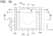
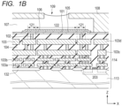
- FIG. 1A and FIG. 1B are enlarged schematic views of a surrounding region of one of the heating resistance elements illustrated in FIG. 15 .
- FIG. 1A is a plan view near the heating resistance element, and
- FIG. 1B is a cross-sectional view taken along the line 1B-1B in FIG. 1A .
- the direction in which current flows toward the heating resistance element is referred to as a first direction X or an X direction
- the direction orthogonal to the first direction X is referred to as a second direction Y or a Y direction.
- the Y direction is the direction in which the heating resistance elements and the ejection orifices are arranged.
- the direction orthogonal to the X direction and the Y direction is referred to as a Z direction.
- the Z direction which is the direction orthogonal to an ejection orifice forming surface, is the direction in which the liquid is ejected.
- an inkjet printer head configured to eject ink for printing characters is described.
- the present invention may be applied to any liquid ejection head configured to eject a liquid.
- the element substrate 100 ( FIG. 15 ) of the liquid ejection head includes a substrate 114 and an ejection orifice forming member 108.
- the substrate 114 includes a base material 113 formed of silicon and an insulating film 104 formed on the base material 113.
- a heating resistance element 101 configured to generate heat energy for ejecting the liquid, a protective film 105, and an anti-cavitation film 106 are arranged on the substrate 114.
- the insulating film 104 is formed of an insulator, such as silicon dioxide.
- an ink supply port 202 extending in a longitudinal direction (matching the Y direction in this embodiment) is arranged in a center portion of the element substrate 100.
- a plurality of heating resistance elements 101 are arranged in lines on both sides of the ink supply port 202.
- the heating resistance elements 101 are formed of a tantalum compound, such as tantalum silicon nitride.
- the thickness (Z direction dimension) of the heating resistance elements 101 is from about 0.01 ⁇ m to about 0.5 ⁇ m, which is considerably smaller than the thickness of an electrical wiring 103, which is described below.
- the ejection orifice forming member 108 is arranged on a surface on which the heating resistance elements 101 of the substrate 114 are formed.
- the ejection orifice forming member 108 includes ejection orifices 109 corresponding to respective heating resistance elements 101.
- the ejection orifice forming member 108 forms a pressure chamber 107 for each ejection orifice 109.
- the pressure chambers 107 are in communication with the ink supply port 202. Ink supplied from the ink supply port 202 is introduced into the pressure chambers 107.
- drive circuits 203 configured to drive the heating resistance elements 101 are arranged on both sides of the ink supply port 202 of the element substrate 100.
- the drive circuits 203 are connected to electrode pads 201 arranged at both ends of the substrate 114 in the longitudinal direction Y.
- the drive circuits 203 are configured to generate a drive current of the heating resistance elements 101 based on a recording signal supplied from the outside of the liquid ejection head via the electrode pads 201.
- Electrical wirings 103 for supplying the current to the heating resistance elements 101 extend into the insulating film 104 arranged on the substrate 114.
- the electrical wirings 103 are arranged so as to be embedded in the insulating film 104.
- the electrical wirings 103 electrically connect the drive circuits 203 and the heating resistance elements 101 via connecting members 102, which are described later.
- the electrical wirings 103 are formed of aluminum and have a thickness (Z direction dimension) of from about 0.6 ⁇ m to about 1.2 ⁇ m.
- the supplied current causes the heating resistance elements 101 to generate heat, with the result that the heating resistance elements 101 becomes hot.
- the hot heating resistance elements 101 heat the ink in the pressure chambers 107, causing air bubbles to form. Ink in the vicinity of the ejection orifices 109 is ejected from the ejection orifices 109 by the air bubbles to thereby perform recording.
- the heating resistance elements 101 are covered by the protective film 105.
- the protective film 105 is formed of silicon nitride, and has a thickness of from about 0.15 ⁇ m to about 0.3 ⁇ m.
- the protective film 105 may also be formed of silicon dioxide or silicon carbide.
- the protective film 105 is covered by the anti-cavitation film 106.
- the anti-cavitation film 106 is formed of tantalum, and has a thickness of from about 0.2 ⁇ m to about 0.3 ⁇ m.
- a plurality of connecting members 102 for connecting the electrical wirings 103 and the heating resistance elements 101 are arranged in the insulating film 104.
- the plurality of connecting members 102 extending in the thickness direction (Z direction) are positioned so that there is a gap between adjacent connecting members 102 in the second direction Y.
- the connecting members 102 connect the electrical wirings 103 and the heating resistance elements 101 in the vicinity of the end portions on both sides of the heating resistance elements 101 in the X direction. Therefore, the current flows through the heating resistance elements 101 in the first direction X.
- Each of the plurality of connecting members 102 is arranged in the vicinity of the end portion of each side of the heating resistance elements 101 in the X direction.
- Each heating resistance element 101 includes, at one end side of the heating resistance element 101 and at another end side of the heating resistance element 101, respectively, a connecting region 110 to which the plurality of connecting members 102 are connected.
- the connecting members 102 are a plug extending in the Z direction from near the end portions of the electrical wirings 103.
- the connecting members 102 have a roughly square-shaped cross-section.
- the connecting members 102 are not limited to having a square shape and may have a rectangular shape.
- the connecting members 102 may have rounded corners, and may have some other shape, such as a round shape or an oval shape. In this case, the connecting members 102 are formed of tungsten.
- the connecting members 102 may be formed of any one of titanium, platinum, cobalt, nickel, molybdenum, tantalum, or silicon, or of a compound of these.
- the connecting members 102 may be integrally formed with the electrical wirings 103.
- the connecting members 102 may be formed integrated with the electrical wirings 103 by cutting a part of the electrical wirings 103 in the thickness direction.
- the connecting regions 110 are the minimum rectangular region including all the connecting members 102 (external connecting region).
- the connecting regions 110 extend in the second direction Y, which is orthogonal to the first direction X.
- the second direction is not necessarily orthogonal to the first direction X.
- the connecting regions 110 may extend in a second direction that intersects the first direction X in a diagonal direction.
- the region in the heating resistance elements 101 actually contributing in ink foaming is called a foaming region 111.
- the foaming region 111 is nearer the inner side of the heating resistance element 101 than the outer periphery of the heating resistance element 101.
- a region between the foaming region 111 and the outer periphery of the heating resistance element 101 (hereinafter referred to as a "frame region 112") is a region that does not contribute to ink foaming. Although heat is also generated in the frame region 112 when electricity is supplied, a large amount of that heat is radiated to the surroundings, and hence the ink is not foamed.
- the dimensions of the foaming region 111 in the X direction and in the Y direction are determined based on the structure of the surroundings of the heating resistance elements 101 and the thermal conductivity of the heating resistance elements 101.
- the connecting regions 110 are arranged on both sides of the frame region 112, adjacent to the foaming region 111 in the first direction X, and extending across a range including the entire length of the foaming region 111 in the second direction Y.
- end portions 110a and 110b of both sides of the connecting regions 110 in the Y direction are closer to peripheral portions 101a and 101b of both sides of the heating resistance elements 101 in the Y direction than peripheral portions 111a and 111b of both sides of the foaming region 111 in the Y direction.
- the current density across the whole of the foaming region 111 is uniform.
- the electrical wirings 103 are arranged in the insulating film 104, and are connected to the heating resistance elements 101 by the connecting members 102.
- the electrical connection to the heating resistance elements 101 is made from the back surface, and hence electrical wirings covering a front surface of the heating resistance elements 101 are not necessary.
- electrical wirings having a thickness of from about 0.6 ⁇ m to about 1.2 ⁇ m are laminated on the heating resistance elements 101, and hence a comparatively thick protective film needs to be arranged in order to ensure good coverage of the steps that are about 0.6 ⁇ m to about 1.2 ⁇ m high.
- the thickness of the heating resistance elements 101 is from about 0.01 ⁇ m to about 0.05 ⁇ m, and hence the steps are considerably smaller than in the related-art configuration. Therefore, because sufficient coverage can be ensured by the protective film 105 having a thickness of from about 0.15 ⁇ m to about 0.3 ⁇ m, the thickness of the protective film 105 can be reduced, which enables a great improvement in the thermal conductivity to the ink. As a result, power consumption can be reduced, and higher image quality can be obtained due to stable foaming.
- connection positions of the connecting members 102 to the heating resistance elements 101 define the actual length (effective length L) of the heating resistance elements 101 in the X direction (refer to FIG. 3 ).
- the effective length L of the heating resistance elements 101 is equal to the gap of the connecting regions 110 on both sides in the X direction. Increasing the dimensional accuracy of the effective length L of the heating resistance elements 101 enables the dimensional accuracy of the length of the foaming region 111 in the X direction to be increased.
- the shape of the heating resistance elements is typically formed by removing the electrical wirings 103 by wet etching, which means that it is difficult to improve the dimensional accuracy of the effective length L of the heating resistance elements 101.
- the connecting members 102 are formed by forming holes in the flat insulating film 104 by dry etching, and embedding the material of the connecting members 102 in the holes. Therefore, compared with the related-art configuration, the dimensional accuracy of the effective length L of the heating resistance elements 101 is relatively high.
- the heating resistance elements 101 can be formed by patterning a thin film of the heating resistance elements 101, which enables the dimensional accuracy of the width W of the heating resistance elements 101 in the Y direction to be increased.
- the heating resistance element film is formed on a flat base layer even when the connecting members 102 are not embedded in holes but are directly connected to the electrical wirings 103 from the holes, highly reliable heating resistance elements can be formed.
- the base layer of the heating resistance elements 101 (lower portion region) be flat. Hitherto, it has been difficult to arrange a wiring pattern and the like directly beneath the heating resistance elements or in the vicinity thereof in a manner that avoids steps from being produced.
- the flatness of the electrical wirings 103 of each layer and the flatness of the base layer portion of the heating resistance elements 101 are increased by performing a treatment such as chemical mechanical planarization (CMP). As a result, as illustrated in FIG.
- CMP chemical mechanical planarization
- an abutting surface of the connecting members 102 with the heating resistance elements 101 and an abutting surface of the insulating film 104 with the heating resistance elements 101 are arranged in the same plane.
- increasing the flatness of the base layer (lower portion region) of a heating resistance layer enables the electrical wirings 103 having a pattern for a signal wiring, a power supply wiring, and the like, to pass directly beneath the heating resistance elements 101 or in the vicinity thereof.
- a transistor may also be arranged in that region, the surface area of the element substrate 100 can be reduced, the cost of the liquid ejection head can be decreased, and the density of the ejection orifices 109 can be increased.
- the drive circuits 203 and a field oxide film 132 are formed at a boundary region of the base material 113 formed of silicon with the insulating film 104.
- the electrical wirings 103 are formed in a four layer configuration. Electrical wirings 103a and 103b on a lower layer side are allocated as signal wirings and logic power supply wirings (third electrical wiring layer and fourth electrical wiring layer) for driving the heating resistance elements 101. Further, electrical wirings 103c and 103d on an upper layer side are allocated as wirings for supplying current to the heating resistance elements 101.
- a ground (GNDH) wiring 103d (first electrical wiring layer) and a power supply (VH) wiring 103c (second electrical wiring layer) are both so-called solid wiring.
- GNDH ground
- VH power supply
- a configuration (solid wiring) in which a first wiring layer and a second wiring layer of the power supply system are arranged as wiring layers formed in different layers, and both wiring layers are arranged over the whole surface of the element substrate enables the wiring resistance to be reduced to a very small value while suppressing an increase in the size of the element substrate 100.
- the insulating film 104 includes four electrical wiring layers, the electrical wiring layers 103c and 103d for causing the current to flow toward the heating resistance elements 101, and the electrical wiring layers 103a and 103b acting as signal wirings and logic power supply wirings for driving the heating resistance elements.
- the electrical wiring layers 103c and 103d are arranged closer to the heating resistance elements than the electrical wiring layers 103a and 103b. It is preferred that those wirings be thick by taking into consideration the fact that thicker wirings are relatively more efficient.
- the electrical wiring layers 103a and 103b are arranged closer to the drive circuits 203 than the electrical wiring layers 103c and 103d. It is preferred that the thickness of those wirings be relatively thinner.
- the heating resistance elements 101 are divided in the first direction X into two electrode regions 121 each including a connecting region 110, and a center region 122 positioned between the two electrode regions 121.
- the two electrode regions 121 and the center region 122 have the same dimension in the second direction Y.
- the heating resistance elements 101 have a rectangular flat shape in the X-Y plane.
- a width a of the connecting members 102, a gap b of the connecting members 102, and an overlap width c of the heating resistance elements 101 are optimized based on such a shape of the heating resistance elements 101.
- the width a of the connecting members 102 is the width of the connecting members 102 in the Y direction
- the gap b of the connecting members 102 is the gap in the second direction Y between adjacent connecting members 102
- the overlap width c is the distance between the connecting members 102 at both the ends and the peripheral portions 101a and 101b of the heating resistance elements 101.
- the arrangement of the connecting members 102 be determined based on the following formula.
- W a min ⁇ n + b min ⁇ n ⁇ 1 + c ⁇ 2 where c ⁇ a min +b min +c min is satisfied.
- a min , b min , and c min which represent the minimum dimension for the layout, depend on the performance of the manufacturing apparatus, such as deviation of the mask during patterning, etching deviation, and deviation of the connecting members 102.
- Formula (1) shows that the maximum number n of the connecting members 102 is arranged based on the width W of the heating resistance elements 101 in the Y direction. Any remaining width is allocated to the overlap width c.
- each electrode region 121 the width a of each of the connecting members 102 is the same, each gap b is the same (the connecting members 102 are arranged at equidistant intervals), and each overlap width c of both sides in the Y direction is the same. Further, the width a and the gap b of the connecting members 102, and the overlap width c are the same for the two electrode regions 121 as well. More specifically, the connecting members 102 of the two electrode regions 121 are arranged in a symmetrical shape in the Y direction. A total of lengths a of n-number of connecting members 102 is 50% or less of the width W of the heating resistance elements 101 in the Y direction.
- FIG. 2 a simulation result of a current density distribution in the heating resistance element 101 according to this embodiment is illustrated.
- the width of the frame region 112 is 2 ⁇ m.
- the simulation is performed by using a simulation program with integrated circuit emphasis (SPICE), in which the heating resistance elements 101 are modelled in a two-dimensional resistance mesh having units of 0.1 ⁇ m and the connecting members 102 are modelled in a three-dimensional mesh.
- SPICE simulation program with integrated circuit emphasis
- the contours of the current density are shown in a range of from -5% to +5% based on the current density of the center portion of the foaming region 111 of the heating resistance element 101.
- the darker sections in FIG. 2 represent a high current density, and the lighter sections in FIG. 2 represent a low current density.
- the effective length L of the heating resistance element 101 is 20 ⁇ m
- the width W of the heating resistance element 101 in the Y direction is 20 ⁇ m
- the width a of the connecting members 102 is 0.6 ⁇ m
- the gap b of the connecting members 102 is 0.6 ⁇ m
- the overlap width c is 0.7 ⁇ m.
- Each width a of the connecting members 102, each gap b of the connecting members 102, and each overlap width c of the heating resistance element 101 is the same.
- the number n of the connecting members 102 is 16 per side.
- the current distribution at the four corners of the heating resistance elements 101 may decrease. Although this is not a problem when the width of the frame region 112 is as described in the first embodiment, depending on the film structure and the thermal conductivity of the heating resistance elements 101, when the width of the frame region 112 is reduced, the decrease in the current distribution at the four corners may be a problem.
- the uniformity of the current distribution is increased.
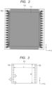
- FIG. 3 The arrangement of the heating resistance element 101 and the connecting members 102 according to this embodiment is illustrated in FIG. 3 .
- each of the symbols in Formula (2) is the same as in the first embodiment, and as illustrated in FIGS. 1A and 1B .
- the current distribution around the connecting members 102 is essentially the same regardless of the position of the connecting members 102.
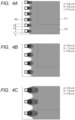
- FIG. 4A to FIG. 4C simulation results of the current density distributions of arrangements of the connecting members 102 satisfying Formula (2) are illustrated.
- the simulation conditions are the same as in the first embodiment.
- the illustrated positions are at the lower left of the heating resistance element 101.
- the width of the frame region 112 is 2 ⁇ m, which is the same as in the first embodiment.
- the gap b of the connecting members 102 is 0.6 ⁇ m in FIG. 4A , 1.2 ⁇ m in FIG. 4B , and 1.8 ⁇ m in FIG.
- each of the symbols in Formula (3) is the same as in the first embodiment, and is as illustrated in FIGS. 1A and 1B .
- the terms a min and b min represent the minimum dimension for the layout.
- this means that the relationship c b/2 is satisfied and that the connecting members 102 are arranged at the minimum possible dimension and with the minimum possible gap in terms of the manufacturing process.
- the width a or the gap b of the connecting members 102 be, while satisfying Formula (2) as far as possible, close to a min or b min .
- the width a of the connecting members 102 is widened, the region having a high current density widens.
- the gap b of the connecting members 102 is widened, the region having a low current density widens.
- the gap b of the connecting members 102 be widened, and when reducing the size of the region having a low current density, it is desired that the width a of the connecting members 102 be widened.
- the width a and the gap b of the connecting members 102 may both be widened.
- the increase in a min or b min be equally allocated among all of the connecting members 102. Similar to the first embodiment, it is desired that the gap b of the connecting members 102 be 1.2 ⁇ m or less.
- the width a or the gap b of the connecting members 102 When it is difficult to equally allocate the increase in a min or b min among all of the connecting members 102, it is acceptable for the width a or the gap b of the connecting members 102 to be non-uniform.
- b in Formula (2) be an average value of the gap b of the connecting members 102 based on one line.
- the overlap width c of both end portions be 1/4 or more to less than one times the average gap of n-number of connecting members 102 in the second direction Y.
- the overlap width c of both end portions in order to increase the current density at the four corners of the heating resistance elements 101, it is desired that the overlap width c of both end portions be 1/4 or more to less than 1/2 the average gap.
- the second embodiment is particularly effective when the overlap width c can be set to a small value.
- the region in which current density is non-uniform may spread as far as the foaming region 111.
- a third embodiment of the present invention not only a decrease in the current density at the four corners of the heating resistance elements 101 can be suppressed, but variation in the current distribution is less likely to occur, which may occur due to variation of the overlap width c and unevenness in the manufacturing positions of the connecting members 102.
- FIG. 5 is a plan view near the heating resistance element 101 according to the third embodiment. Similar to the first embodiment, the heating resistance element 101 is divided in the first direction X into the two electrode regions 121 each including the connecting region 110, and the center region 122 positioned between the two electrode regions 121. However, unlike the first embodiment, the two electrode regions 121 are longer than the center region 122 in the second direction Y. The width of the electrode regions 121 in the Y direction may be set independently of the width of the center region 122 in the Y direction. As a result, the connecting members 102 may be arranged in the electrode regions 121 without being subject to the width restriction of the center region 122 in the Y direction, which allows connecting regions 110 that is large in the Y direction to be obtained.
- the current density at the four corners of the heating resistance elements 101 can be increased. Even if deviation occurs in the manufacturing positions of the connecting members 102, the current density at the four corners does not decrease. Further, in this embodiment, more connecting members 102 can be arranged than in the first embodiment or in the second embodiment. As a result, the number of connecting members 102 (resistors) connected in parallel to each other is increased, and a voltage loss of the connecting members 102 is decreased, leading to reduced power consumption.
- the plurality of connecting members 102 are positioned so that there is a gap between adjacent connecting members 102 in the second direction Y.
- the width a of each of the connecting members 102 is essentially the same
- each gap b is essentially the same (the connecting members 102 are arranged at equidistant intervals)
- each overlap width c of both sides in the Y direction is essentially the same.
- the width a and the gap b of the connecting members 102, and the overlap width c are essentially the same for the two electrode regions 121 as well. More specifically, in the two electrode regions 121, the connecting members 102 are arranged in a symmetrical shape in the Y direction.
- the total of the widths of n-number of connecting members 102 in the Y direction is 50% or less of the width of the electrode regions 121 in the Y direction. Similar to the first embodiment, it is desired that the gap b of the connecting members 102 be 1.2 ⁇ m or less.
- the connecting regions 110 are arranged within a range of the center region 122 in the second direction Y. Specifically, the two connecting members 102 positioned at the end portions in the Y direction (hereinafter referred to as end portion connecting members 102a and 102b) are arranged further inward than peripheral portions of the center region 122. In the other embodiments, a part of the connecting regions 110 may be arranged outside of the range of the center region 122 in the second direction Y.
- a distance between the side of the end portion connecting members 102a and 102b on the external side and the peripheral portions of the center region 122 is referred to as a lead distance d.
- FIG. 6 a simulation result of the current distribution according to this embodiment is illustrated.
- the simulation conditions are the same as in the first embodiment and the second embodiment.
- the width a of the connecting members 102 is 0.6 ⁇ m
- the gap b of the connecting members 102 is 0.6 ⁇ m
- the overlap width c is 0.6 ⁇ m
- the lead distance d is 0.1 ⁇ m.
- the width of the electrode regions 121 in the Y direction is larger than in the first embodiment, and hence 17 connecting members 102 are arranged, which is one more than in the first embodiment.
- the width of the frame region 112 is 2 ⁇ m, which is the same as in the first embodiment and the second embodiment. As illustrated in FIG. 6 , the width of the electrode regions 121 in the Y direction is wide, and hence a decrease in the current density at the four corners is suppressed.
- FIG. 7A to FIG. 7C the current densities at various positions of the connecting members 102 are illustrated.
- FIG. 7A is an enlarged diagram of a lower left portion of the heating resistance element 101 illustrated in FIG. 6 .
- FIG. 7B and FIG. 7C the positions of the end portion connecting members 102a and 102b are shifted toward the inner side of the heating resistance element 101 from the positions illustrated in FIG. 7A .
- the region in which the current is non-uniform widens, but in this embodiment, as illustrated in FIG. 7C , the region in which the current is non-uniform decreases in size.
- FIG. 8 is a diagram in which the contour range of the simulation result in FIG. 7C is widened. As can be seen from FIG. 8 , current is flowing through the end portion connecting member 102a side. Because the width of the electrode regions 121 in the Y direction is wide, the current flowing from the end portions of the connecting regions 110 to the outside in the Y direction increases, which results in a different current distribution from the first embodiment.
- the current distribution may be made uniform by widening the connecting regions 110 in the Y direction.
- the region in which the current distribution is non-uniform can be minimized by arranging the connecting members 102 only on the side further inward than the width of the center region 122 in the Y direction.
- the overlap width c on both sides in the Y direction be larger than the gap b of the connecting members 102, and more commonly, it is desired that the overlap width c on both sides in the Y direction be larger than the average gap of the connecting members 102 in the second direction Y.
- FIG. 9 is a plan view near the heating resistance element 101 according to a fourth embodiment of the present invention.
- the two electrode regions 121 and the center region 122 have the same dimension in the second direction Y, and the heating resistance element 101 has a rectangular flat shape.
- the connecting members 102 are arranged continuously in the second direction Y. In other words, the connecting regions 110 are completely filled with the connecting members 102.
- the connecting members 102 are formed having a slit-like rectangular shape, which allows the current density in the heating resistance element 101 to be more uniform than in the first embodiment to the third embodiment.
- FIG. 10 a simulation result according to this embodiment is illustrated.
- the resistance of the connecting members 102 is large because the connecting members 102 are divided in the Y direction.
- a voltage loss of about 1% occurs for an ideal quadrilateral-shaped heating resistance element 101 (in which current flows uniformly through the entire width of the heating resistance element 101).
- the voltage loss is 0.1% or less, which means that energy can be applied to the heating resistance element 101 with hardly any voltage loss.
- the current distribution is uniform, and an ideal configuration of the heating resistance element 101 can be obtained.
- FIG. 11A and FIG. 11B simulation results when the end portion positions of the connecting members 102 have been shifted are illustrated.
- FIG. 11A the lower left portion of the heating resistance element 101 illustrated in FIG. 10 is enlarged.
- FIG. 11B the end portion positions of the connecting members 102 illustrated in FIG. 10 have been shifted in the Y direction (the width of the connecting members 102 in the Y direction has changed).
- the overlap width c is 0.6 ⁇ m
- FIG. 11B the overlap width c is 0.1 ⁇ m.
- the overlap width c becomes smaller and smaller, the region in which the current is non-uniform becomes less and less, and the current distribution is more ideal.
- FIG. 12 is a plan view near the heating resistance element 101 according to a fifth embodiment of the present invention.
- the two electrode regions 121 and the center region 122 have different dimensions in the second direction Y, and the shape of the heating resistance element 101 is the same as in the third embodiment.
- the connecting members 102 are arranged continuously in the second direction Y.
- the shape of the connecting members 102 is the same as in the fourth embodiment. Therefore, similar to the fourth embodiment, the voltage loss of the connecting members 102 is very small.
- forming the connecting members 102 in a slit-like rectangular shape allows the current density of the heating resistance element 101 to be more uniform than in the first embodiment to the third embodiment.
- FIG. 13 a simulation result according to this embodiment is illustrated.
- the voltage loss is 0.1% or less, which means that energy can be applied to the heating resistance element 101 with hardly any voltage loss.
- the current distribution is uniform, and an ideal configuration of the heating resistance element 101 can be obtained.
- FIG. 14A to FIG. 14C simulation results when the end portion positions of the connecting members 102 have been shifted are illustrated.
- FIG. 14A the lower left portion of the heating resistance element 101 illustrated in FIG. 13 is enlarged.
- FIG. 14B and FIG. 14C the end portion positions of the connecting members 102 illustrated in FIG. 13 have been shifted in the Y direction (the width of the connecting members 102 in the Y direction has changed).
- the overlap width c is 1.1 ⁇ m and the lead distance d is 0.6 ⁇ m.
- FIG. 14B the overlap width c is 0.6 ⁇ m and the lead distance d is 0.1 ⁇ m.
- FIG. 14A the overlap width c is 1.1 ⁇ m and the lead distance d is 0.6 ⁇ m.
- FIG. 14B the overlap width c is 0.6 ⁇ m and the lead distance d is 0.1 ⁇ m.
- the overlap width c is 0.9 ⁇ m and the lead distance d is 0.4 ⁇ m. From FIG. 14A and FIG. 14B , it can be seen that in the case of the heating resistance element 101 in which the electrode regions 121 are wider than the center region 122, when the overlap width c is reduced, the region in which the current is non-uniform conversely increases in size. Similar to the principles discussed in the third embodiment, this is due to the current coming around from the end portions of the connecting members 102. In the case of the shape of the heating resistance element according to this embodiment, it is preferred to set the overlap width c and the lead distance d to have a certain dimension in order to obtain a uniform current density distribution. The region in which the current is non-uniform is minimized when c in FIG. 14C is 0.9 ⁇ m and d in FIG. 14C is 0.4 ⁇ m. It is preferred that the lead distance d be 0.6 ⁇ m or less.
- the relative positions of the actual heating resistance elements 101 and the connecting members 102 may be different from the simulation results depending on manufacturing accuracy and unevenness.
- the optimum values or the preferred values of the width a and the gap b of the connecting members 102, the overlap width c, and the lead distance d shown in the simulation results may vary in a range of about ⁇ 0.1 ⁇ m.
- the optimum range of the overlap width c that minimizes the region in which the current is non-uniform is from 0.8 ⁇ m or more to 1.0 ⁇ m or less, and the optimum range of the lead distance d is from 0.3 ⁇ m or more to 0.5 ⁇ m or less.
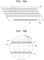
- FIG. 16A and FIG. 16B a configuration of an element substrate 100 according to a sixth embodiment of the present invention is illustrated.
- FIG. 16A is a plan view of the surface of the element substrate 100 in which the ejection orifices 109 are formed.
- FIG. 16B is an enlarged view of the portion A illustrated in FIG. 16A .
- the outer periphery of the element substrate 100 according to this embodiment is shaped roughly like a parallelogram.
- the ejection orifice forming member 108 of the element substrate 100 four lines of ejection orifices corresponding to cyan, magenta, yellow, and black (CMYK), respectively, are formed in two dimensions. Note that, in the following description, the direction that the ejection orifice lines in which the plurality of ejection orifices 109 are arranged extend is referred to as an "ejection orifice line direction".
- recording elements 101 which are heating resistance elements for causing a liquid to be foamed by heat energy, are arranged at positions corresponding to the ejection orifices 109, respectively.
- the pressure chambers 107 which include the recording elements 101, are partitioned by a partition 303.
- the recording elements 101 are electrically connected to the electrode pads 201 illustrated in FIG. 16A by electrical wirings 103c and 103d (refer to FIG. 1B ) arranged in the element substrate 100.
- the recording elements 101 are configured to cause the liquid to boil by generating heat based on a pulse signal input from a control circuit of a recording device (not shown).
- the liquid is ejected from the ejection orifices 109 by the force of the air bubbles produced by this boiling.
- a liquid supply channel 301 is extended on one side of each ejection orifice line, and a liquid recovery channel 302 is extended on another side.
- the liquid supply channel 301 and the liquid recovery channel 302 are flow channels that are arranged on the base material 113 of the element substrate 100 and are configured to extend in the ejection orifice line direction.
- the liquid supply channel 301 and the liquid recovery channel 302 are both in communication with the ejection orifices 109 via a supply port 300a and a recovery port 300b, respectively.
- the supply port 300a and the recovery port 300b are through holes passing through the substrate 114 of the element substrate 100 (refer to FIG. 1B ).
- the liquid flowing through the liquid supply channel 301 is supplied to the recording elements 101 via a plurality of supply ports 300a, and ejected from the ejection orifices 109.
- liquid that has not been ejected is recovered in the liquid recovery channel 302 via a plurality of recovery ports 300b.
- the liquid recovered in the liquid recovery channel 302 is again supplied to the liquid ejection head via a tank portion arranged in the recording device. The liquid travels this flow route to be circulated.
- the present invention is not limited to the circulation configuration described in this embodiment.
- the liquid may be supplied to the recording elements 101 from the liquid recovery channel 302 via the recovery ports 300b.
- Such a configuration is preferred, as this configuration allows the liquid to be supplied to the recording elements 101 from openings (300a and 300b) formed on both sides of the recording elements 101, enables ejection symmetry to be obtained, and also allows refilling after ejection of the liquid to be performed comparatively quickly.
- an element substrate 100 such as that in this embodiment, which includes a plurality of ejection orifice lines (lines of the recording elements 101) and a plurality of liquid openings (e.g., supply port 300a and recovery port 300b), which pass through the substrate 114
- the multi-layer wiring configuration illustrated in FIG. 1B is especially preferred.
- an element substrate 100 that suppresses an increase in the size of the substrate can be obtained by using the multi-layer wiring of the electrical wirings 103a and 103b and through hole configuration.
- arranging a plurality of the element substrates 100 enables a line-type liquid ejection head having a length corresponding to the width of the recording medium to be provided.
- a line-type liquid ejection head having a length corresponding to the width of the recording medium to be provided.
- the outer periphery of the element substrates 100 roughly like a parallelogram, and arranging the plurality of element substrates 100 in a straight line (in-line) as in this embodiment, a compact line-type liquid ejection head that has a suppressed length in the short direction can be provided.
- An element substrate of a liquid ejection head includes: a base material; an insulating film positioned on the base material; a heating resistance element for generating heat energy for ejecting a liquid; a protective film for covering the heating resistance element; a first electrical wiring layer arranged in the insulating film, for supplying a current to the heating resistance element; a second electrical wiring layer arranged on a layer different from the first electrical wiring layer in the insulating film, for supplying a current to the heating resistance element; and at least one connecting member extending into the insulating film to connect the first electrical wiring layer and the heating resistance element, for causing the current to flow in a first direction, the heating resistance element including a connecting region, extending in a second direction intersecting the first direction, to which the at least one connecting member is connected.
Landscapes
- Particle Formation And Scattering Control In Inkjet Printers (AREA)
Claims (23)
- Elementsubstrat (100) eines Flüssigkeitsausstoßkopfes, mit:einem Basismaterial (114),einem an dem Basismaterial positionierten Isolationsfilm (104),einem Heizwiderstandselement (101), das dazu eingerichtet ist, um Heizenergie für einen Ausstoß einer Flüssigkeit zu erzeugen,einem Schutzfilm (105), der dazu eingerichtet ist, um das Heizwiderstandselement abzudecken,einer ersten Elektroverdrahtungsschicht (103), die in dem Isolationsfilm angeordnet ist und dazu eingerichtet ist, um einen Strom zu dem Heizwiderstandselement zuzuführen,einer zweiten Elektroverdrahtungsschicht (103), die bei einer Schicht verschieden von der ersten Elektroverdrahtungsschicht in dem Isolationsfilm angeordnet ist und dazu eingerichtet ist, um einen Strom zu dem Heizwiderstandselement zuzuführen, undeiner Vielzahl von Verbindungselementen (102), die dazu eingerichtet sind, um sich in den Isolationsfilm zu erstrecken, um die erste Elektroverdrahtungsschicht und das Heizwiderstandselement zu verbinden, wobeidas Heizwiderstandselement dazu eingerichtet ist, um den Strom in einer ersten Richtung (X) fließen zu lassen,das Heizwiderstandselement einen Verbindungsbereich (110) aufweist, mit dem die Vielzahl von Verbindungselementen verbunden ist,sich der Verbindungsbereich in einer zweiten Richtung (Y) erstreckt, die die erste Seite schneidet, unddas Heizwiderstandselement in der ersten Richtung unterteilt ist in zwei Elektrodenbereiche (121), von denen jeder den Verbindungsbereich aufweist, und einen Zentralbereich (122), der zwischen den zwei Elektrodenbereichen positioniert ist,dadurch gekennzeichnet, dassdie Anordnung der Vielzahl von Verbindungselementen bestimmt ist basierend auf den Formeln
 wobei eine Breite a [µm] eine Breite der Verbindungselemente in der zweiten Richtung repräsentiert, eine Beabstandung b [µm] eine Beabstandung zwischen benachbarten Verbindungselementen in der zweiten Richtung repräsentiert, ein Überlapp c [µm] eine Distanz zwischen den Verbindungselementen an beiden der Enden und Umfangsabschnitten (101a, 101b) des Heizwiderstandselement repräsentiert, amin, bmin, cmin die Minimalabmessung der Anordnung repräsentieren, n eine Maximalanzahl der Vielzahl von Verbindungselementen repräsentiert, und W [µm] eine Breite der Heizwiderstandselemente in der zweiten Richtung repräsentiert.
 - Elementsubstrat (100) eines Flüssigkeitsausstoßkopfes nach Anspruch 1, wobei eine Angrenzoberfläche der Vielzahl von Verbindungselementen (102) mit dem Heizwiderstandselement (101) und eine Angrenzoberfläche des Isolationsfilms (104) mit dem Heizwiderstandselement in der gleichen Ebene angeordnet sind.
- Elementsubstrat (100) eines Flüssigkeitsausstoßkopfes nach Anspruch 1 oder 2, wobei die Vielzahl von Verbindungselementen (102) durch das Heizwiderstandselement (101), wenn von einer Richtung orthogonal zu einer Oberfläche, an der das Heizwiderstandselement angeordnet ist, betrachtet, abgedeckt ist.
- Elementsubstrat (100) eines Flüssigkeitsausstoßkopfes nach einem der Ansprüche 1 bis 3, ferner mit einer dritten Elektroverdrahtungsschicht in einer Schicht verschieden von der ersten Elektroverdrahtungsschicht (103) und der zweiten Elektroverdrahtungsschicht (103) in dem Isolationsfilm (104), die eine Logikenergiezufuhrverdrahtung für eine Ansteuerung des Heizwiderstandselements (101) aufweist.
- Elementsubstrat (100) eines Flüssigkeitsausstoßkopfes nach einem der Ansprüche 1 bis 4, ferner mit einer vierten Elektroverdrahtungsschicht in einer Schicht verschieden von der ersten Elektroverdrahtungsschicht (103) und der zweiten Elektroverdrahtungsschicht (103) in dem Isolationsfilm (104), die eine Signalverdrahtung für eine Ansteuerung des Heizwiderstandselements (101) aufweist.
- Elementsubstrat (100) eines Flüssigkeitsausstoßkopfes nach Anspruch 4, wobei die erste Elektroverdrahtungsschicht (103) und die zweite Elektroverdrahtungsschicht (103) an einer Seite näher zu dem Heizwiderstandselement (101) als die dritte Elektroverdrahtungsschicht angeordnet sind.
- Elementsubstrat (100) eines Flüssigkeitsausstoßkopfes nach einem der Ansprüche 1 bis 6,wobei das Heizwiderstandselement (101) einen Schäumbereich aufweist, der in der ersten Richtung (X) benachbart zu dem Verbindungsbereich (101) angeordnet ist, und in dem die Flüssigkeit geschäumt ist, undwobei sich der Verbindungsbereich über eine Spanne einschließlich einer Gesamtlänge des Schäumbereichs in der zweiten Richtung (Y) erstreckt.
- Elementsubstrat (100) eines Flüssigkeitsausstoßkopfes nach einem der Ansprüche 1 bis 7, wobei die Vielzahl von Verbindungselementen (102) einen Stecker aufweist, der dazu eingerichtet ist, um sich in den Isolationsfilm (104) zu erstrecken.
- Elementsubstrat (100) eines Flüssigkeitsausstoßkopfes nach einem der Ansprüche 1 bis 8,wobei das Heizwiderstandselement (101) in der ersten Richtung in zwei Elektrodenbereiche (121), von denen jeder die Vielzahl von Verbindungselementen (102) aufweist, und einen Zentralbereich (122), der zwischen den zwei Elektrodenbereichen positioniert ist, unterteilt ist, undwobei die zwei Elektrodenbereiche und der Zentralbereich die gleiche Abmessung in der zweiten Richtung (Y) aufweisen.
- Elementsubstrat (100) eines Flüssigkeitsausstoßkopfes nach einem der Ansprüche 1 bis 9, wobei eine Vielzahl der Verbindungselemente (102) in der zweiten Richtung (Y) mit einer Beabstandung zwischen benachbarten Verbindungselementen positioniert ist.
- Elementsubstrat (100) eines Flüssigkeitsausstoßkopfes nach Anspruch 9, wobei eine Gesamtheit von Längen einer Vielzahl der Verbindungselemente (102) in der zweiten Richtung (Y) 50% oder weniger einer Länge der zwei Elektrodenbereiche (121) in der zweiten Richtung beträgt.
- Elementsubstrat (100) eines Flüssigkeitsausstoßkopfes nach Anspruch 10 oder 11, wobei zwei der Vielzahl von Verbindungselementen (102) an beiden Endabschnitten in der zweiten Richtung (Y) mit der gleichen Distanz von einem Umfangsabschnitt (101a, 101b) des Heizwiderstandselements (101) in der zweiten Richtung getrennt sind.
- Elementsubstrat (100) eines Flüssigkeitsausstoßkopfes nach Anspruch 12, wobei eine Distanz zwischen jedem der zwei der Vielzahl von Verbindungselementen (102) an beiden der Endabschnitte in der zweiten Richtung (Y) und dem Umfangsabschnitt (101a, 101b) des Heizwiderstandselements (101) 1/4 oder mehr bis weniger als ein Mal einer Durchschnittsbeabstandung der Vielzahl von Verbindungselementen in der zweiten Richtung beträgt.
- Elementsubstrat (100) eines Flüssigkeitsausstoßkopfes nach einem der Ansprüche 1 bis 9, wobei die Verbindungselemente (102) kontinuierlich in der zweiten Richtung (Y) angeordnet sind.
- Elementsubstrat (100) eines Flüssigkeitsausstoßkopfes nach Anspruch 14, wobei die Verbindungselemente (102) durch die gleiche Distanz von einem Umfangsabschnitt (101a, 101b) beider Seiten des Heizwiderstandselements (101) in der zweiten Richtung (Y) getrennt sind.
- Elementsubstrat (100) eines Flüssigkeitsausstoßkopfes nach einem der Ansprüche 1 bis 8,wobei das Heizwiderstandselement (101) in der ersten Richtung (X) in zwei Elektrodenbereiche (121), von denen jeder die Vielzahl von Verbindungselementen (102) aufweist, und einen Zentralbereich (122), der zwischen den zwei Elektrodenbereichen positioniert ist, unterteilt ist, undwobei die zwei Elektrodenbereiche eine Abmessung länger als eine Abmessung des Zentralbereichs in der zweiten Richtung (Y) aufweisen.
- Elementsubstrat (100) eines Flüssigkeitsausstoßkopfes nach Anspruch 16, wobei der Verbindungsbereich (110) innerhalb einer Spanne des Zentralbereichs (122) in der zweiten Richtung (Y) angeordnet ist.
- Elementsubstrat eines Flüssigkeitsausstoßkopfes nach Anspruch 16 oder 17, wobei eine Vielzahl der Verbindungselemente (102) in der zweiten Richtung (Y) mit einer Beabstandung zwischen benachbarten Verbindungselementen positioniert ist.
- Elementsubstrat (100) eines Flüssigkeitsausstoßkopfes nach Anspruch 18, wobei eine Distanz zwischen jedem der zwei der Vielzahl von Verbindungselementen (102) an beiden Endabschnitten in der zweiten Richtung (Y) und einem Umfangsabschnitt (101a, 101b) des Heizwiderstandselements (101) der zwei Elektrodenbereiche (121) größer als eine Durchschnittsbeabstandung einer Vielzahl der Verbindungselemente in der zweiten Richtung ist.
- Elementsubstrat (100) eines Flüssigkeitsausstoßkopfes nach Anspruch 16 oder 17, wobei die Verbindungselemente (102) kontinuierlich in der zweiten Richtung (Y) angeordnet sind.
- Elementsubstrat (100) eines Flüssigkeitsausstoßkopfes nach einem der Ansprüche 1 bis 20,wobei das Heizwiderstandselement (101) in der ersten Richtung (X) in zwei Elektrodenbereiche (121), von denen jeder die Vielzahl von Verbindungselementen (102) aufweist, und einen Zentralbereich (122), der zwischen den zwei Elektrodenbereichen positioniert ist, unterteilt ist, undwobei ein Teil der ersten Elektroverdrahtungsschicht (103) und ein Teil der zweiten Elektroverdrahtungsschicht (103) in einem unteren Abschnittsbereich des Zentralbereichs angeordnet sind.
- Elementsubstrat (100) eines Flüssigkeitsausstoßkopfes nach einem der Ansprüche 1 bis 21,wobei das Heizwiderstandselement (101) in der ersten Richtung (X) in zwei Elektrodenbereiche (121), von denen jeder die Vielzahl von Verbindungselementen (102) aufweist, und einen Zentralbereich (122), der zwischen den zwei Elektrodenbereichen positioniert ist, unterteilt ist, undwobei ein Transistor in einem unteren Abschnittsbereich des Zentralbereichs angeordnet ist.
- Flüssigkeitsausstoßkopf mit einem Elementsubstrat (100) nach einem der Ansprüche 1 bis 22.
Applications Claiming Priority (3)
| Application Number | Priority Date | Filing Date | Title |
|---|---|---|---|
| JP2015013197 | 2015-01-27 | ||
| JP2015233689A JP6598658B2 (ja) | 2015-01-27 | 2015-11-30 | 液体吐出ヘッドの素子基板及び液体吐出ヘッド |
| EP16152512.6A EP3050707B1 (de) | 2015-01-27 | 2016-01-25 | Elementsubstrat und flüssigkeitsausstosskopf |
Related Parent Applications (2)
| Application Number | Title | Priority Date | Filing Date |
|---|---|---|---|
| EP16152512.6A Division-Into EP3050707B1 (de) | 2015-01-27 | 2016-01-25 | Elementsubstrat und flüssigkeitsausstosskopf |
| EP16152512.6A Division EP3050707B1 (de) | 2015-01-27 | 2016-01-25 | Elementsubstrat und flüssigkeitsausstosskopf |
Publications (2)
| Publication Number | Publication Date |
|---|---|
| EP3970977A1 EP3970977A1 (de) | 2022-03-23 |
| EP3970977B1 true EP3970977B1 (de) | 2025-04-23 |
Family
ID=55229598
Family Applications (2)
| Application Number | Title | Priority Date | Filing Date |
|---|---|---|---|
| EP21202653.8A Active EP3970977B1 (de) | 2015-01-27 | 2016-01-25 | Elementsubstrat und flüssigkeitsausstosskopf |
| EP16152512.6A Active EP3050707B1 (de) | 2015-01-27 | 2016-01-25 | Elementsubstrat und flüssigkeitsausstosskopf |
Family Applications After (1)
| Application Number | Title | Priority Date | Filing Date |
|---|---|---|---|
| EP16152512.6A Active EP3050707B1 (de) | 2015-01-27 | 2016-01-25 | Elementsubstrat und flüssigkeitsausstosskopf |
Country Status (2)
| Country | Link |
|---|---|
| US (2) | US10035346B2 (de) |
| EP (2) | EP3970977B1 (de) |
Families Citing this family (12)
| Publication number | Priority date | Publication date | Assignee | Title |
|---|---|---|---|---|
| US10035346B2 (en) | 2015-01-27 | 2018-07-31 | Canon Kabushiki Kaisha | Element substrate and liquid ejection head |
| JP6833363B2 (ja) * | 2016-06-30 | 2021-02-24 | キヤノン株式会社 | 液体吐出ヘッド用基板、液体吐出ヘッド、及び記録装置 |
| JP2018024126A (ja) | 2016-08-08 | 2018-02-15 | キヤノン株式会社 | 素子基板、記録ヘッド、及び記録装置 |
| JP7037334B2 (ja) | 2017-02-17 | 2022-03-16 | キヤノン株式会社 | 液体吐出ヘッド用基板、その製造方法、液体吐出ヘッド及び液体吐出装置 |
| US10300698B2 (en) | 2017-06-05 | 2019-05-28 | Canon Kabushiki Kaisha | Liquid ejection head |
| JP6942537B2 (ja) * | 2017-06-29 | 2021-09-29 | キヤノン株式会社 | 液体吐出ヘッド |
| JP2019010769A (ja) | 2017-06-29 | 2019-01-24 | キヤノン株式会社 | 液体吐出ヘッド用基板および液体吐出ヘッド |
| EP3470228B1 (de) | 2017-10-11 | 2021-06-30 | Canon Kabushiki Kaisha | Elementsubstrat, herstellungsverfahren dafür, druckkopf und druckvorrichtung |
| JP7344669B2 (ja) | 2019-04-23 | 2023-09-14 | キヤノン株式会社 | 素子基板、液体吐出ヘッド、及び記録装置 |
| JP7328787B2 (ja) | 2019-04-23 | 2023-08-17 | キヤノン株式会社 | 素子基板、液体吐出ヘッド、及び記録装置 |
| JP7729172B2 (ja) * | 2021-10-25 | 2025-08-26 | セイコーエプソン株式会社 | 液体吐出装置、及び駆動回路基板 |
| JP7767828B2 (ja) | 2021-10-25 | 2025-11-12 | セイコーエプソン株式会社 | 液体吐出装置、及び駆動回路基板 |
Citations (1)
| Publication number | Priority date | Publication date | Assignee | Title |
|---|---|---|---|---|
| US20150290935A1 (en) * | 2014-04-15 | 2015-10-15 | Canon Kabushiki Kaisha | Recording-element substrate and liquid ejection apparatus |
Family Cites Families (11)
| Publication number | Priority date | Publication date | Assignee | Title |
|---|---|---|---|---|
| JP2708557B2 (ja) | 1988-07-26 | 1998-02-04 | キヤノン株式会社 | 液体噴射記録ヘッド用素子基板,液体噴射記録ヘッド,ヘッドカートリッジおよび記録装置 |
| JP2839964B2 (ja) | 1991-04-20 | 1998-12-24 | キヤノン株式会社 | 記録ヘッド用基体および記録ヘッドの製造方法 |
| US6142606A (en) | 1997-12-22 | 2000-11-07 | Canon Kabushiki Kaisha | Ink jet recording head, substrate for use of such head, ink jet cartridge, and ink jet recording apparatus |
| US6382782B1 (en) | 2000-12-29 | 2002-05-07 | Eastman Kodak Company | CMOS/MEMS integrated ink jet print head with oxide based lateral flow nozzle architecture and method of forming same |
| JP2005067164A (ja) * | 2003-08-28 | 2005-03-17 | Sony Corp | 液体吐出ヘッド、液体吐出装置及び液体吐出ヘッドの製造方法 |
| KR100717023B1 (ko) | 2005-08-27 | 2007-05-10 | 삼성전자주식회사 | 잉크젯 프린트헤드 및 그 제조방법 |
| JP2008307828A (ja) | 2007-06-15 | 2008-12-25 | Canon Inc | 記録ヘッド |
| JP5328608B2 (ja) | 2008-12-15 | 2013-10-30 | キヤノン株式会社 | 液体吐出ヘッド用基板、液体吐出ヘッド及びそれらの製造方法 |
| JP5404121B2 (ja) | 2009-03-25 | 2014-01-29 | キヤノン株式会社 | 記録基板、該記録基板の製造方法及び液体吐出ヘッド |
| JP5606213B2 (ja) | 2009-09-04 | 2014-10-15 | キヤノン株式会社 | 液体吐出ヘッド用基板の製造方法 |
| US10035346B2 (en) | 2015-01-27 | 2018-07-31 | Canon Kabushiki Kaisha | Element substrate and liquid ejection head |
-
2016
- 2016-01-19 US US15/000,544 patent/US10035346B2/en active Active
- 2016-01-25 EP EP21202653.8A patent/EP3970977B1/de active Active
- 2016-01-25 EP EP16152512.6A patent/EP3050707B1/de active Active
-
2018
- 2018-06-27 US US16/019,714 patent/US10814623B2/en active Active
Patent Citations (1)
| Publication number | Priority date | Publication date | Assignee | Title |
|---|---|---|---|---|
| US20150290935A1 (en) * | 2014-04-15 | 2015-10-15 | Canon Kabushiki Kaisha | Recording-element substrate and liquid ejection apparatus |
Also Published As
| Publication number | Publication date |
|---|---|
| US20160214384A1 (en) | 2016-07-28 |
| EP3050707A2 (de) | 2016-08-03 |
| US10035346B2 (en) | 2018-07-31 |
| EP3050707B1 (de) | 2022-01-12 |
| EP3970977A1 (de) | 2022-03-23 |
| US10814623B2 (en) | 2020-10-27 |
| US20180370233A1 (en) | 2018-12-27 |
| EP3050707A3 (de) | 2016-11-23 |
Similar Documents
| Publication | Publication Date | Title |
|---|---|---|
| EP3050707B1 (de) | Elementsubstrat und flüssigkeitsausstosskopf | |
| TWI610820B (zh) | 元件基板及液體噴出頭 | |
| US8083322B2 (en) | Ink-jet recording head | |
| KR100977645B1 (ko) | 액체 토출 헤드 | |
| US7918539B2 (en) | Liquid discharge head | |
| EP3470228B1 (de) | Elementsubstrat, herstellungsverfahren dafür, druckkopf und druckvorrichtung | |
| US6126277A (en) | Non-kogating, low turn on energy thin film structure for very low drop volume thermal ink jet pens | |
| JP5038460B2 (ja) | 液体吐出ヘッド | |
| US20060077233A1 (en) | Ink jet recording head and ink discharge method | |
| US7896474B2 (en) | Liquid ejection head and recording apparatus | |
| JP5031534B2 (ja) | インクジェット記録ヘッド | |
| EP3412462B1 (de) | Flüssigkeitsausstosskopf | |
| US11090940B2 (en) | Liquid ejection head | |
| JP5675133B2 (ja) | 液体吐出ヘッド用基板及び液体吐出ヘッド | |
| CN2536399Y (zh) | 喷墨头芯片 | |
| JPH0952361A (ja) | インクジェット記録装置 | |
| JPH0952362A (ja) | インクジェット記録装置 |
Legal Events
| Date | Code | Title | Description |
|---|---|---|---|
| PUAI | Public reference made under article 153(3) epc to a published international application that has entered the european phase |
Free format text: ORIGINAL CODE: 0009012 |
|
| STAA | Information on the status of an ep patent application or granted ep patent |
Free format text: STATUS: THE APPLICATION HAS BEEN PUBLISHED |
|
| AC | Divisional application: reference to earlier application |
Ref document number: 3050707 Country of ref document: EP Kind code of ref document: P |
|
| AK | Designated contracting states |
Kind code of ref document: A1 Designated state(s): AL AT BE BG CH CY CZ DE DK EE ES FI FR GB GR HR HU IE IS IT LI LT LU LV MC MK MT NL NO PL PT RO RS SE SI SK SM TR |
|
| STAA | Information on the status of an ep patent application or granted ep patent |
Free format text: STATUS: REQUEST FOR EXAMINATION WAS MADE |
|
| 17P | Request for examination filed |
Effective date: 20220330 |
|
| RBV | Designated contracting states (corrected) |
Designated state(s): AL AT BE BG CH CY CZ DE DK EE ES FI FR GB GR HR HU IE IS IT LI LT LU LV MC MK MT NL NO PL PT RO RS SE SI SK SM TR |
|
| STAA | Information on the status of an ep patent application or granted ep patent |
Free format text: STATUS: EXAMINATION IS IN PROGRESS |
|
| 17Q | First examination report despatched |
Effective date: 20230728 |
|
| GRAP | Despatch of communication of intention to grant a patent |
Free format text: ORIGINAL CODE: EPIDOSNIGR1 |
|
| STAA | Information on the status of an ep patent application or granted ep patent |
Free format text: STATUS: GRANT OF PATENT IS INTENDED |
|
| INTG | Intention to grant announced |
Effective date: 20241218 |
|
| GRAS | Grant fee paid |
Free format text: ORIGINAL CODE: EPIDOSNIGR3 |
|
| GRAA | (expected) grant |
Free format text: ORIGINAL CODE: 0009210 |
|
| STAA | Information on the status of an ep patent application or granted ep patent |
Free format text: STATUS: THE PATENT HAS BEEN GRANTED |
|
| AC | Divisional application: reference to earlier application |
Ref document number: 3050707 Country of ref document: EP Kind code of ref document: P |
|
| AK | Designated contracting states |
Kind code of ref document: B1 Designated state(s): AL AT BE BG CH CY CZ DE DK EE ES FI FR GB GR HR HU IE IS IT LI LT LU LV MC MK MT NL NO PL PT RO RS SE SI SK SM TR |
|
| REG | Reference to a national code |
Ref country code: GB Ref legal event code: FG4D |
|
| REG | Reference to a national code |
Ref country code: CH Ref legal event code: EP |
|
| REG | Reference to a national code |
Ref country code: DE Ref legal event code: R096 Ref document number: 602016092041 Country of ref document: DE |
|
| REG | Reference to a national code |
Ref country code: IE Ref legal event code: FG4D |
|
| REG | Reference to a national code |
Ref country code: NL Ref legal event code: MP Effective date: 20250423 |
|
| PG25 | Lapsed in a contracting state [announced via postgrant information from national office to epo] |
Ref country code: NL Free format text: LAPSE BECAUSE OF FAILURE TO SUBMIT A TRANSLATION OF THE DESCRIPTION OR TO PAY THE FEE WITHIN THE PRESCRIBED TIME-LIMIT Effective date: 20250423 |
|
| REG | Reference to a national code |
Ref country code: AT Ref legal event code: MK05 Ref document number: 1787423 Country of ref document: AT Kind code of ref document: T Effective date: 20250423 |
|
| PG25 | Lapsed in a contracting state [announced via postgrant information from national office to epo] |
Ref country code: PT Free format text: LAPSE BECAUSE OF FAILURE TO SUBMIT A TRANSLATION OF THE DESCRIPTION OR TO PAY THE FEE WITHIN THE PRESCRIBED TIME-LIMIT Effective date: 20250825 Ref country code: FI Free format text: LAPSE BECAUSE OF FAILURE TO SUBMIT A TRANSLATION OF THE DESCRIPTION OR TO PAY THE FEE WITHIN THE PRESCRIBED TIME-LIMIT Effective date: 20250423 Ref country code: ES Free format text: LAPSE BECAUSE OF FAILURE TO SUBMIT A TRANSLATION OF THE DESCRIPTION OR TO PAY THE FEE WITHIN THE PRESCRIBED TIME-LIMIT Effective date: 20250423 |
|
| REG | Reference to a national code |
Ref country code: LT Ref legal event code: MG9D |
|
| PG25 | Lapsed in a contracting state [announced via postgrant information from national office to epo] |
Ref country code: GR Free format text: LAPSE BECAUSE OF FAILURE TO SUBMIT A TRANSLATION OF THE DESCRIPTION OR TO PAY THE FEE WITHIN THE PRESCRIBED TIME-LIMIT Effective date: 20250724 Ref country code: NO Free format text: LAPSE BECAUSE OF FAILURE TO SUBMIT A TRANSLATION OF THE DESCRIPTION OR TO PAY THE FEE WITHIN THE PRESCRIBED TIME-LIMIT Effective date: 20250723 |
|
| PG25 | Lapsed in a contracting state [announced via postgrant information from national office to epo] |
Ref country code: PL Free format text: LAPSE BECAUSE OF FAILURE TO SUBMIT A TRANSLATION OF THE DESCRIPTION OR TO PAY THE FEE WITHIN THE PRESCRIBED TIME-LIMIT Effective date: 20250423 |
|
| PG25 | Lapsed in a contracting state [announced via postgrant information from national office to epo] |
Ref country code: BG Free format text: LAPSE BECAUSE OF FAILURE TO SUBMIT A TRANSLATION OF THE DESCRIPTION OR TO PAY THE FEE WITHIN THE PRESCRIBED TIME-LIMIT Effective date: 20250423 |
|
| PG25 | Lapsed in a contracting state [announced via postgrant information from national office to epo] |
Ref country code: HR Free format text: LAPSE BECAUSE OF FAILURE TO SUBMIT A TRANSLATION OF THE DESCRIPTION OR TO PAY THE FEE WITHIN THE PRESCRIBED TIME-LIMIT Effective date: 20250423 |
|
| PG25 | Lapsed in a contracting state [announced via postgrant information from national office to epo] |
Ref country code: AT Free format text: LAPSE BECAUSE OF FAILURE TO SUBMIT A TRANSLATION OF THE DESCRIPTION OR TO PAY THE FEE WITHIN THE PRESCRIBED TIME-LIMIT Effective date: 20250423 |
|
| PG25 | Lapsed in a contracting state [announced via postgrant information from national office to epo] |
Ref country code: RS Free format text: LAPSE BECAUSE OF FAILURE TO SUBMIT A TRANSLATION OF THE DESCRIPTION OR TO PAY THE FEE WITHIN THE PRESCRIBED TIME-LIMIT Effective date: 20250723 |
|
| PG25 | Lapsed in a contracting state [announced via postgrant information from national office to epo] |
Ref country code: IS Free format text: LAPSE BECAUSE OF FAILURE TO SUBMIT A TRANSLATION OF THE DESCRIPTION OR TO PAY THE FEE WITHIN THE PRESCRIBED TIME-LIMIT Effective date: 20250823 |
|
| PG25 | Lapsed in a contracting state [announced via postgrant information from national office to epo] |
Ref country code: LV Free format text: LAPSE BECAUSE OF FAILURE TO SUBMIT A TRANSLATION OF THE DESCRIPTION OR TO PAY THE FEE WITHIN THE PRESCRIBED TIME-LIMIT Effective date: 20250423 |
|
| PGFP | Annual fee paid to national office [announced via postgrant information from national office to epo] |
Ref country code: GB Payment date: 20251219 Year of fee payment: 11 |
|
| PG25 | Lapsed in a contracting state [announced via postgrant information from national office to epo] |
Ref country code: DK Free format text: LAPSE BECAUSE OF FAILURE TO SUBMIT A TRANSLATION OF THE DESCRIPTION OR TO PAY THE FEE WITHIN THE PRESCRIBED TIME-LIMIT Effective date: 20250423 Ref country code: SM Free format text: LAPSE BECAUSE OF FAILURE TO SUBMIT A TRANSLATION OF THE DESCRIPTION OR TO PAY THE FEE WITHIN THE PRESCRIBED TIME-LIMIT Effective date: 20250423 |
|
| PG25 | Lapsed in a contracting state [announced via postgrant information from national office to epo] |
Ref country code: CZ Free format text: LAPSE BECAUSE OF FAILURE TO SUBMIT A TRANSLATION OF THE DESCRIPTION OR TO PAY THE FEE WITHIN THE PRESCRIBED TIME-LIMIT Effective date: 20250423 |
|
| PG25 | Lapsed in a contracting state [announced via postgrant information from national office to epo] |
Ref country code: EE Free format text: LAPSE BECAUSE OF FAILURE TO SUBMIT A TRANSLATION OF THE DESCRIPTION OR TO PAY THE FEE WITHIN THE PRESCRIBED TIME-LIMIT Effective date: 20250423 |
|
| REG | Reference to a national code |
Ref country code: DE Ref legal event code: R097 Ref document number: 602016092041 Country of ref document: DE |
|
| PG25 | Lapsed in a contracting state [announced via postgrant information from national office to epo] |
Ref country code: SK Free format text: LAPSE BECAUSE OF FAILURE TO SUBMIT A TRANSLATION OF THE DESCRIPTION OR TO PAY THE FEE WITHIN THE PRESCRIBED TIME-LIMIT Effective date: 20250423 Ref country code: RO Free format text: LAPSE BECAUSE OF FAILURE TO SUBMIT A TRANSLATION OF THE DESCRIPTION OR TO PAY THE FEE WITHIN THE PRESCRIBED TIME-LIMIT Effective date: 20250423 |
|
| PG25 | Lapsed in a contracting state [announced via postgrant information from national office to epo] |
Ref country code: IT Free format text: LAPSE BECAUSE OF FAILURE TO SUBMIT A TRANSLATION OF THE DESCRIPTION OR TO PAY THE FEE WITHIN THE PRESCRIBED TIME-LIMIT Effective date: 20250423 |
|
| PLBE | No opposition filed within time limit |
Free format text: ORIGINAL CODE: 0009261 |
|
| STAA | Information on the status of an ep patent application or granted ep patent |
Free format text: STATUS: NO OPPOSITION FILED WITHIN TIME LIMIT |
|
| REG | Reference to a national code |
Ref country code: CH Ref legal event code: L10 Free format text: ST27 STATUS EVENT CODE: U-0-0-L10-L00 (AS PROVIDED BY THE NATIONAL OFFICE) Effective date: 20260304 |
|
| 26N | No opposition filed |
Effective date: 20260126 |
|
| PGFP | Annual fee paid to national office [announced via postgrant information from national office to epo] |
Ref country code: DE Payment date: 20251217 Year of fee payment: 11 |