EP3967501B1 - Tintenstrahldüsengesundheits- und -druckzuverlässigkeit - Google Patents
Tintenstrahldüsengesundheits- und -druckzuverlässigkeit Download PDFInfo
- Publication number
- EP3967501B1 EP3967501B1 EP21181753.1A EP21181753A EP3967501B1 EP 3967501 B1 EP3967501 B1 EP 3967501B1 EP 21181753 A EP21181753 A EP 21181753A EP 3967501 B1 EP3967501 B1 EP 3967501B1
- Authority
- EP
- European Patent Office
- Prior art keywords
- ink
- nozzles
- nozzle
- print head
- Prior art date
- Legal status (The legal status is an assumption and is not a legal conclusion. Google has not performed a legal analysis and makes no representation as to the accuracy of the status listed.)
- Active
Links
Images



Classifications
-
- B—PERFORMING OPERATIONS; TRANSPORTING
- B41—PRINTING; LINING MACHINES; TYPEWRITERS; STAMPS
- B41J—TYPEWRITERS; SELECTIVE PRINTING MECHANISMS, i.e. MECHANISMS PRINTING OTHERWISE THAN FROM A FORME; CORRECTION OF TYPOGRAPHICAL ERRORS
- B41J2/00—Typewriters or selective printing mechanisms characterised by the printing or marking process for which they are designed
- B41J2/005—Typewriters or selective printing mechanisms characterised by the printing or marking process for which they are designed characterised by bringing liquid or particles selectively into contact with a printing material
- B41J2/01—Ink jet
- B41J2/135—Nozzles
- B41J2/165—Prevention or detection of nozzle clogging, e.g. cleaning, capping or moistening for nozzles
- B41J2/16517—Cleaning of print head nozzles
- B41J2/16535—Cleaning of print head nozzles using wiping constructions
- B41J2/16538—Cleaning of print head nozzles using wiping constructions with brushes or wiper blades perpendicular to the nozzle plate
-
- B—PERFORMING OPERATIONS; TRANSPORTING
- B41—PRINTING; LINING MACHINES; TYPEWRITERS; STAMPS
- B41J—TYPEWRITERS; SELECTIVE PRINTING MECHANISMS, i.e. MECHANISMS PRINTING OTHERWISE THAN FROM A FORME; CORRECTION OF TYPOGRAPHICAL ERRORS
- B41J2/00—Typewriters or selective printing mechanisms characterised by the printing or marking process for which they are designed
- B41J2/005—Typewriters or selective printing mechanisms characterised by the printing or marking process for which they are designed characterised by bringing liquid or particles selectively into contact with a printing material
- B41J2/01—Ink jet
- B41J2/015—Ink jet characterised by the jet generation process
- B41J2/04—Ink jet characterised by the jet generation process generating single droplets or particles on demand
- B41J2/045—Ink jet characterised by the jet generation process generating single droplets or particles on demand by pressure, e.g. electromechanical transducers
- B41J2/04501—Control methods or devices therefor, e.g. driver circuits, control circuits
- B41J2/0451—Control methods or devices therefor, e.g. driver circuits, control circuits for detecting failure, e.g. clogging, malfunctioning actuator
-
- B—PERFORMING OPERATIONS; TRANSPORTING
- B41—PRINTING; LINING MACHINES; TYPEWRITERS; STAMPS
- B41J—TYPEWRITERS; SELECTIVE PRINTING MECHANISMS, i.e. MECHANISMS PRINTING OTHERWISE THAN FROM A FORME; CORRECTION OF TYPOGRAPHICAL ERRORS
- B41J2/00—Typewriters or selective printing mechanisms characterised by the printing or marking process for which they are designed
- B41J2/005—Typewriters or selective printing mechanisms characterised by the printing or marking process for which they are designed characterised by bringing liquid or particles selectively into contact with a printing material
- B41J2/01—Ink jet
- B41J2/17—Ink jet characterised by ink handling
- B41J2/1707—Conditioning of the inside of ink supply circuits, e.g. flushing during start-up or shut-down
-
- B—PERFORMING OPERATIONS; TRANSPORTING
- B41—PRINTING; LINING MACHINES; TYPEWRITERS; STAMPS
- B41J—TYPEWRITERS; SELECTIVE PRINTING MECHANISMS, i.e. MECHANISMS PRINTING OTHERWISE THAN FROM A FORME; CORRECTION OF TYPOGRAPHICAL ERRORS
- B41J2/00—Typewriters or selective printing mechanisms characterised by the printing or marking process for which they are designed
- B41J2/005—Typewriters or selective printing mechanisms characterised by the printing or marking process for which they are designed characterised by bringing liquid or particles selectively into contact with a printing material
- B41J2/01—Ink jet
-
- B—PERFORMING OPERATIONS; TRANSPORTING
- B41—PRINTING; LINING MACHINES; TYPEWRITERS; STAMPS
- B41J—TYPEWRITERS; SELECTIVE PRINTING MECHANISMS, i.e. MECHANISMS PRINTING OTHERWISE THAN FROM A FORME; CORRECTION OF TYPOGRAPHICAL ERRORS
- B41J2/00—Typewriters or selective printing mechanisms characterised by the printing or marking process for which they are designed
- B41J2/005—Typewriters or selective printing mechanisms characterised by the printing or marking process for which they are designed characterised by bringing liquid or particles selectively into contact with a printing material
- B41J2/01—Ink jet
- B41J2/015—Ink jet characterised by the jet generation process
- B41J2/04—Ink jet characterised by the jet generation process generating single droplets or particles on demand
- B41J2/045—Ink jet characterised by the jet generation process generating single droplets or particles on demand by pressure, e.g. electromechanical transducers
- B41J2/04501—Control methods or devices therefor, e.g. driver circuits, control circuits
- B41J2/04586—Control methods or devices therefor, e.g. driver circuits, control circuits controlling heads of a type not covered by groups B41J2/04575 - B41J2/04585, or of an undefined type
-
- B—PERFORMING OPERATIONS; TRANSPORTING
- B41—PRINTING; LINING MACHINES; TYPEWRITERS; STAMPS
- B41J—TYPEWRITERS; SELECTIVE PRINTING MECHANISMS, i.e. MECHANISMS PRINTING OTHERWISE THAN FROM A FORME; CORRECTION OF TYPOGRAPHICAL ERRORS
- B41J2/00—Typewriters or selective printing mechanisms characterised by the printing or marking process for which they are designed
- B41J2/005—Typewriters or selective printing mechanisms characterised by the printing or marking process for which they are designed characterised by bringing liquid or particles selectively into contact with a printing material
- B41J2/01—Ink jet
- B41J2/135—Nozzles
- B41J2/165—Prevention or detection of nozzle clogging, e.g. cleaning, capping or moistening for nozzles
- B41J2/16517—Cleaning of print head nozzles
-
- B—PERFORMING OPERATIONS; TRANSPORTING
- B41—PRINTING; LINING MACHINES; TYPEWRITERS; STAMPS
- B41J—TYPEWRITERS; SELECTIVE PRINTING MECHANISMS, i.e. MECHANISMS PRINTING OTHERWISE THAN FROM A FORME; CORRECTION OF TYPOGRAPHICAL ERRORS
- B41J2/00—Typewriters or selective printing mechanisms characterised by the printing or marking process for which they are designed
- B41J2/005—Typewriters or selective printing mechanisms characterised by the printing or marking process for which they are designed characterised by bringing liquid or particles selectively into contact with a printing material
- B41J2/01—Ink jet
- B41J2/135—Nozzles
- B41J2/165—Prevention or detection of nozzle clogging, e.g. cleaning, capping or moistening for nozzles
- B41J2/16517—Cleaning of print head nozzles
- B41J2/16535—Cleaning of print head nozzles using wiping constructions
-
- B—PERFORMING OPERATIONS; TRANSPORTING
- B41—PRINTING; LINING MACHINES; TYPEWRITERS; STAMPS
- B41J—TYPEWRITERS; SELECTIVE PRINTING MECHANISMS, i.e. MECHANISMS PRINTING OTHERWISE THAN FROM A FORME; CORRECTION OF TYPOGRAPHICAL ERRORS
- B41J2/00—Typewriters or selective printing mechanisms characterised by the printing or marking process for which they are designed
- B41J2/005—Typewriters or selective printing mechanisms characterised by the printing or marking process for which they are designed characterised by bringing liquid or particles selectively into contact with a printing material
- B41J2/01—Ink jet
- B41J2/135—Nozzles
- B41J2/165—Prevention or detection of nozzle clogging, e.g. cleaning, capping or moistening for nozzles
- B41J2/16517—Cleaning of print head nozzles
- B41J2/16535—Cleaning of print head nozzles using wiping constructions
- B41J2/16544—Constructions for the positioning of wipers
- B41J2/16547—Constructions for the positioning of wipers the wipers and caps or spittoons being on the same movable support
-
- B—PERFORMING OPERATIONS; TRANSPORTING
- B41—PRINTING; LINING MACHINES; TYPEWRITERS; STAMPS
- B41J—TYPEWRITERS; SELECTIVE PRINTING MECHANISMS, i.e. MECHANISMS PRINTING OTHERWISE THAN FROM A FORME; CORRECTION OF TYPOGRAPHICAL ERRORS
- B41J2/00—Typewriters or selective printing mechanisms characterised by the printing or marking process for which they are designed
- B41J2/005—Typewriters or selective printing mechanisms characterised by the printing or marking process for which they are designed characterised by bringing liquid or particles selectively into contact with a printing material
- B41J2/01—Ink jet
- B41J2/135—Nozzles
- B41J2/165—Prevention or detection of nozzle clogging, e.g. cleaning, capping or moistening for nozzles
- B41J2/16517—Cleaning of print head nozzles
- B41J2/16552—Cleaning of print head nozzles using cleaning fluids
-
- B—PERFORMING OPERATIONS; TRANSPORTING
- B41—PRINTING; LINING MACHINES; TYPEWRITERS; STAMPS
- B41J—TYPEWRITERS; SELECTIVE PRINTING MECHANISMS, i.e. MECHANISMS PRINTING OTHERWISE THAN FROM A FORME; CORRECTION OF TYPOGRAPHICAL ERRORS
- B41J2/00—Typewriters or selective printing mechanisms characterised by the printing or marking process for which they are designed
- B41J2/005—Typewriters or selective printing mechanisms characterised by the printing or marking process for which they are designed characterised by bringing liquid or particles selectively into contact with a printing material
- B41J2/01—Ink jet
- B41J2/17—Ink jet characterised by ink handling
- B41J2/175—Ink supply systems ; Circuit parts therefor
-
- B—PERFORMING OPERATIONS; TRANSPORTING
- B41—PRINTING; LINING MACHINES; TYPEWRITERS; STAMPS
- B41J—TYPEWRITERS; SELECTIVE PRINTING MECHANISMS, i.e. MECHANISMS PRINTING OTHERWISE THAN FROM A FORME; CORRECTION OF TYPOGRAPHICAL ERRORS
- B41J2/00—Typewriters or selective printing mechanisms characterised by the printing or marking process for which they are designed
- B41J2/005—Typewriters or selective printing mechanisms characterised by the printing or marking process for which they are designed characterised by bringing liquid or particles selectively into contact with a printing material
- B41J2/01—Ink jet
- B41J2/17—Ink jet characterised by ink handling
- B41J2/175—Ink supply systems ; Circuit parts therefor
- B41J2/17503—Ink cartridges
- B41J2/17513—Inner structure
-
- B—PERFORMING OPERATIONS; TRANSPORTING
- B41—PRINTING; LINING MACHINES; TYPEWRITERS; STAMPS
- B41J—TYPEWRITERS; SELECTIVE PRINTING MECHANISMS, i.e. MECHANISMS PRINTING OTHERWISE THAN FROM A FORME; CORRECTION OF TYPOGRAPHICAL ERRORS
- B41J2/00—Typewriters or selective printing mechanisms characterised by the printing or marking process for which they are designed
- B41J2/005—Typewriters or selective printing mechanisms characterised by the printing or marking process for which they are designed characterised by bringing liquid or particles selectively into contact with a printing material
- B41J2/01—Ink jet
- B41J2/17—Ink jet characterised by ink handling
- B41J2/175—Ink supply systems ; Circuit parts therefor
- B41J2/17566—Ink level or ink residue control
Definitions
- the present disclosure relates to nozzle health for ink jet printers.
- US 7 717 540 B1 discloses a method comprising pumping, in response to detecting if a triggering event has occurred, and circulating ink.
- ink jet printers such as piezoelectric ink jet printers
- have a number of uses such as, for example, using ink to print on paper as well as substrate surfaces, such as plastic, used for identification cards (e.g., government-issued licenses, workplace identification cards, or the like).
- identification cards e.g., government-issued licenses, workplace identification cards, or the like.
- performance of the ink jet nozzles it is common for performance of the ink jet nozzles to be reduced over time (e.g., by becoming clogged) which, in turn, reduces print quality.
- a system may generally include a processor and memory, including instructions stored thereon which, when executed by the processor, cause the processor to monitor whether a triggering event has occurred.
- the triggering event may be an elapsed period of time.
- the elapsed period of time may be an amount of time the printer has been powered off, an amount of time the printer has remained idle, an amount of time the printer has been in a low-power mode, or an amount of time since an ink cartridge has been manually agitated, shaken, or the like.
- the period of time may be determined by the processor (e.g., 8 hours of idle time), or manually selected by a user.
- the processor may cause at least a portion of ink contained in a header tank, the header tank included as a part, component, or the like, of a scan head, to be pumped, moved, or the like, in a direction from the header tank toward the ink cartridge, for example, through one or more tubes connecting the ink cartridges to the header tank.
- the system may circulate the ink from the direction toward the ink cartridge back into the header tank.
- the header tank may include a level sensor that the system may use to monitor a level of ink in the header tank (e.g., to prevent the header tank from overfilling as ink is circulated back into it).
- the system may further agitate the scan head by causing the scan head to move in at least one of: a left-to-right direction, a right-to-left direction, a back-to-front direction, or front-to-back direction, along an x-y gantry.
- the system may also, optionally, apply a "tickle pulse" to the print head to further mix the ink to be ejected from the print head.
- a "tickle pulse” may include the processor causing a waveform (e.g., a current, voltage, or pulsed voltage in which the pulses are a controlled voltage stepped upward or downward) to be applied to the print head that is not strong enough to eject a drop of ink from a nozzle in the print head, but will mix the ink within the print head.
- a waveform e.g., a current, voltage, or pulsed voltage in which the pulses are a controlled voltage stepped upward or downward
- the method for improving ink jet nozzle health and printing reliability of the inkjet printer may include, moving a scan head to a maintenance station.
- the maintenance station may include a purge cap and a wiper (e.g., a printhead ink purging reservoir and a separate printhead nozzle plate wiper), and the scan head may include at least a header tank, and a print head operatively connected to the header tank.
- the print head may include a nozzle plate, the nozzle plate including at least one row of nozzles containing a plurality of nozzles.
- the method may further include creating at least a partial seal between the purge cap and at least one of: a particular nozzle of the plurality of nozzles, the row of nozzles, the nozzle plate, or the print head.
- the method may also include performing a reverse purge of at least one of: a particular nozzle of the plurality of nozzles, the row of nozzles, the nozzle plate, or the print head.
- the reverse purging may include applying a positive pressure using the purge cap by reversing a direction of a vacuum pump (e.g., a peristaltic pump).
- the reverse purging may cause at least a portion of ink located in at least one nozzle of the plurality of nozzles to be pushed, moved, or the like, through at least one nozzle in a direction toward the header tank.
- the direction of the vacuum pump may optionally be reversed again (e.g., to turn, operate, move, rotate, or the like, in a forward direction) causing the vacuum pump, using the purge cap, to apply a negative pressure to suck ink, clogs, obstructions, or the like, through at least one nozzle of the plurality of nozzles.
- the method may further include ejecting an amount of ink from the print head and activating the wiper to move across the nozzle plate simultaneously or substantially simultaneously with the ejecting of the amount of ink.
- the amount of ink may be cleaned from the wiper by rotating the wiper about an axle, causing the amount of ink to enter a waste deposit located below the wiper and the axle.
- the amount of ink (e.g., waste ink) may then be removed from the waste deposit using the vacuum pump, or a second vacuum pump.
- the method may also include printing a first image onto a first substrate using the print head.
- the print head may begin printing the first image from a first starting position above the first substrate.
- particular ones of the plurality of nozzles included on the print head may be used, while other particular ones of the plurality of nozzles may not be used.
- the method may further include randomizing a second starting position relative to the first starting position.
- the method may then include printing a second image onto a second substrate using the print head, wherein the print head begins the printing of the second image from the second starting position.
- the first image may be identical to at least a portion of the second image.
- the first substrate may be substantially the same size as the second substrate.
- at least one nozzle of the particular ones of the plurality of nozzles used in printing the first image may not be used.
- at least one of the other particular ones of the plurality of nozzles not used when printing the first image may be used.
- different nozzles on the print head may be used, utilized, or the like, when printing the first image than are used/utilized when printing the second image, to prevent nozzles from remaining dormant or unused for an extended period of time.
- ink jet printing with pigmented ink can be challenging because the pigment in the ink may have relatively large particles.
- inks include, for example, inks containing titanium-dioxide pigment. Large particles can settle out of solution and lead to clogged nozzles (e.g., printhead nozzles, such as piezoelectric printhead nozzles) or reduce the opacity of the ink.
- some of the ink jet nozzles may not be utilized during the printing, depending on, for example, the size, shape, and/or location of the image to be printed on a substrate. When nozzles are left idle for an extended period of time, they may not stay primed, leading to poor jetting characteristics due to pigment settling.
- FIG. 1 illustrates an example of the interior 100 of a printer employing systems and methods described herein.
- the interior 100 of the printer may include a print carriage configured to hold one or more ink cartridges.
- This may include cartridges containing pigmented ink such as black, white, cyan, yellow, magenta, or the like, or unpigmented varnish (e.g., a clear coat).
- Ink may be fed/sent/moved, or the like, from the ink cartridges via one or more tubes, or one or more series of tubes, located in the interior 100 of the printer, to one or more header tanks.
- the header tanks may be a component, part, or the like, of a scan assembly/scan head which may also include print heads from which ink is ejected, dropped, deposited, or the like.
- the scan assembly may be movable in multiple directions (e.g., horizontally/left-to-right/right-to-left, and back and forth) along a gantry, rails, or the like, to allow for printing over an entire surface of a substrate.
- the scan assembly may also be movable over a maintenance station, configured to clean the print heads, or nozzles on the print head nozzle plate (e.g., clearing clogs, removing excess ink, or the like).
- the interior 100 of the printer may include a scan head 102 that moves along an x-y gantry.
- the gantry may include a x-direction gantry/scan rail 104 and at least one y-direction gantry/scan rail 106.
- the x-direction gantry 104 may allow the scan head 102 to move in a substantially sideways/horizontal direction (e.g., left-to-right or right-to-left), or more generally, along a first axis (e.g., an x-axis).
- the y-direction gantry 106 may allow the scan head 102 to move substantially perpendicular to the x-direction gantry 104 (e.g., forward and backward, front-to-back, back-to-front, or the like), or more generally, along a second axis (e.g., a y-axis). This may allow the scan head 102 to print with complete coverage over a card surface 108 without having to reposition the card surface 108.
- the interior 100 may further include a print cartridge carriage 110 configured to hold, contain, or the like, one or more print/ink cartridges 112 containing ink.
- a print cartridge carriage 110 configured to hold, contain, or the like, one or more print/ink cartridges 112 containing ink.
- Each ink cartridge, such as ink cartridge 112 may be connected to a header tank (as shown and described in FIG.
- a tube 116 e.g., a hose, tubing, or any similar flexible material capable of containing and moving ink
- a tube 116 may be efficiently located (e.g., run along, fed, or the like) along, near, through, proximate to (e.g., behind), or the like, a flexible or semi-flexible chain 114 or other type of linking mechanism located along a side and rear of the interior 100 and capable of moving with or otherwise accommodating movement of the scan head 102.
- the tube 116 may connect to the ink cartridge 112 in an area below the ink cartridge 112 or the print cartridge carriage 110 and connect to a pump, such as a peristaltic pump shown and described in FIG.
- the tube 116 may be connected to the scan head 102 by locating the tube 116 along the chain 114 which runs to the scan head 102. It is understood that there may be more than one tube or series of tubes, such as tube 116, as needed, and that the tubes may be located in the interior 100 along any suitable path, route, or the like, from the ink cartridges, such as ink cartridge 112, or the print cartridge carriage 110 to the header tanks.
- the system may contain one tube per ink cartridge feeding to one header tank (as described below) or there may be multiple tubes per ink cartridge feeding ink to multiple header tanks, or multiple chambers of a single header tank.
- the interior 100 may also include a maintenance station 500, as described below in FIG. 5 , configured to clean, clear, or otherwise maintain the print heads located on the bottom of the scan head 102.
- the maintenance station 500 may include a purge cap 502 and a wiper 504 as discussed below, configured to clean the print heads (discussed below in FIG. 3 ).
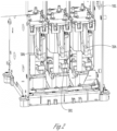
- FIG. 2 illustrates an example of header tanks connected to print heads.
- the scan head may contain one or more header tanks which are fed ink from the ink cartridges through the tubing, such as tube 116, as described above for FIG. 1 .
- the header tanks may, in turn, contain one or more chambers into which the ink or varnish from the ink cartridges is contained.
- a header tank may have a single chamber containing a pigmented ink, or, alternatively, two or more chambers (e.g., dual chambers).
- one of the chambers may contain a pigmented ink while the other chamber contains a different colored pigmented ink.
- one or more chambers may contain a varnish/clear coat.
- the scan head 102 may include header tanks 200, 202, 204 which contain ink directed from corresponding ink cartridges, such as ink cartridge 112, via tubing, such as tube 116, located along the chain 114, as described above for FIG. 1 .
- the chain 114 may be located behind the scan head 100 and allows tubing, such as tube 116 from the ink cartridges, such as ink cartridge 112, to connect to a corresponding one of the header tanks, such as header tanks 200, 202, 204, located in scan head 102.
- the header tanks 200, 202, 204 may be dual chamber tanks, which feed ink to print heads, and nozzles located on the print heads (as described below), which are located below the header tanks 200, 202, 204.
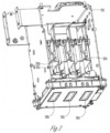
- FIG. 3 illustrates an example of print heads connected to header tanks, such as header tanks 200, 202, 204.
- the header tanks may be operatively connected to print heads.
- a single header tank may be connected to a corresponding one of the print heads, and feed ink from the chamber or chambers of the header tank (in the example of a dual or multi chamber tank) to the print heads through nozzles located on a nozzle plate on the bottom of the print heads (as described below).
- print heads 300, 302, 304 may be located on a bottom/lower surface of the scan head 102, and connected to the header tanks 200, 202, 204.
- header tank 200 may correspond to print head 300, while header tank 202 may correspond to print head 302, and header tank 204 may correspond to print head 304.
- the system may include multiple single-channel header tanks, one or more of which may be operatively connected to one or more print heads (e.g., six header tanks connected to some combination of three or more print heads).
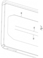
- FIG. 4 illustrates an example of a partial nozzle plate 400 of a print head, such as print heads 300, 302, or 304 including a plurality of print nozzles.
- the system may include multiple nozzle plates (e.g., one or more nozzle plates per print head).
- the nozzle plates of the print heads may contain one or more rows of nozzles through which ink from the chambers of the header tanks, such as header tanks 200, 202, or 204 is ejected, dropped, or the like, into the interior 100 such as onto card surface 108.
- multiple header tanks may be operatively connected to a single print head such that ink from one header tank is ejected from a particular first row of nozzles on the nozzle plate, and ink from another header tank is ejected from the other of the row of nozzles (e.g., a second row of nozzles) on the nozzle plate.
- a single header tank may be connected such that ink from that tank is only ejected from particular nozzles in a row of nozzles on the nozzle plate.
- the present disclosure is not to be limited by any particular configuration or connection between the header tanks, print heads, and nozzles.
- each print head 300, 302, or 304 may include a nozzle plate, such as nozzle plate 400 which may be formed from a piezoelectric or another similar material.
- the nozzle plate 400 may, in turn, include a first row of print nozzles 402 and a second row of print nozzles 404, each row including a plurality of individual nozzles.
- Each individual nozzle in the rows of nozzles 402 and 404 is configured to eject, drop, spit, or the like, ink from a particular one of the header tanks, such as header tanks 200, 202, or 204 connected to a particular one of the print heads, such as print heads 300, 302, or 304.
- FIG. 5 illustrates an example of a maintenance station 500 including a purge cap 502 and wiper 504.
- the maintenance station may be located below the scan head 102, and may be used to clean the print heads and/or the nozzle plate utilizing a vacuum pump and/or a wiper to remove clogs or other similar obstructions in the nozzles, or to wipe, remove, or the like, ink from the print heads.
- the system may employ a "spitting while wiping" process (described in detail below) to clean the print heads 300, 302, 304, and the nozzle plate 400 corresponding to the particular print head 300, 302, or 304.
- the maintenance station 500 may be located or included in/within the interior 100 of the printer, such as below the scan head 102.
- the maintenance station may be fixed, stationary, or the like, below the scan head 102.
- the scan head 102 may be movable to the maintenance station 500 (e.g., by moving/lowering the scan head downward). Moving the scan head to the maintenance station may place one or more of the print heads, or the nozzle plates of the print heads, in a position so as to be cleaned (e.g., one or more nozzles to be cleared of a clog or other similar obstruction).
- the maintenance station may be configured to move to the scan head 102 (e.g., upward), to place the maintenance station into a position to clean the print heads, nozzle plate, or nozzles, as described above.
- an amount of ink may be ejected from a print head, such as print head 300, 302, or 304, (e.g., from one or more of the nozzles in the row of nozzles 402 or 404), e.g., onto the nozzle plate 400.
- a wiper 504 is located on, near, or within the maintenance station 500 and may be configured to move (e.g., laterally, left-to-right, right-to-left, side-to-side, or the like) below the print heads 300, 302, 304 and each of the print heads' corresponding nozzle plate, such as nozzle plate 400. Additionally, or alternatively, the wiper 504 may rotate about/around an axle 506.
- the wiper 504 may be formed from a flexible material such as rubber or another similar material.
- the wiper 504 may be formed in the shape of a blade with at least an edge configured to contact the surface of the nozzle plate 400 and wipe against the nozzle plate as the wiper is moved laterally and/or is rotated, as described above.
- the wiper 504 may, simultaneously or substantially simultaneously with the ejection of the ink from at least one nozzle in the row of nozzles 402, 404 onto the nozzle plate 400, wipe the nozzle plate 400 clean of ink.
- ejected ink may be prevented from being pushed back into the nozzles and mixing with "clean" ink, or being re-ejected, re-dropped, re-spit, or the like from, the print heads 300, 302, or 304 during a subsequent print operation or print job.
- the wiper 504 may rotate about the axle 506 which may be a cylindrical rod connected, attached, or the like, to the wiper 504 which allows the wiper 504 to additionally wipe against a piece of material 512 (e.g., plastic, metal, or the like) allowing ink to be cleared from the wiper 504.
- Waste ink wiped from the nozzles, nozzle plate, or print heads may collect on the surface of the wiper 504, as the wiper moves below the print heads/nozzles/nozzle plates, and when the wiper 504 is rotated about the axle 506, the waste ink may be removed (e.g., scraped off) from the wiper as it makes contact with the material 512.
- the waste ink may fall or otherwise caused to be moved below the wiper 504 and axle 506, into a waste deposit 510, which may be a well, depression, opening, compartment, or the like, at which point, the waste ink may be removed from the maintenance station 500, such as by being sucked/vacuumed, or the like, from the maintenance station 500 using a vacuum pump, such as 600 as shown and described in FIG. 6 , below.
- a vacuum pump such as 600 as shown and described in FIG. 6 , below.
- the maintenance station 500 may also include a purge cap 502 which may be used as a part of a reverse purging process in conjunction with a vacuum pump such as pump 600 shown in FIG. 6 .
- the purge cap 502 may be located below the print heads as the print heads/scan head moves to the maintenance station 500 as described above.
- the purge cap 502 may additionally or alternatively move to the scan head 102 (e.g., move with the maintenance station to the scan head), so as to locate the purge cap 502 below one or more nozzles in one of the row of nozzles 402, 404, on the nozzle plate 400.
- the nozzles 402, 404, or the nozzle plate 400 may be operably positioned over the purge cap 502 such that at least a partial seal may be made around one or more nozzle, an entire row of nozzles, such as 402, 404, or an entire print head, such as 300, 302, or 304.
- the vacuum pump 600 may be reversed so as to apply a positive pressure through the purge cap 502 causing ink, a clog, or an obstruction in one or more nozzles of the rows of nozzles 402, 404 to be pushed into the nozzle (e.g., in a direction toward the header tanks 200, 202, 204), in a "reverse purge" process.
- the vacuum pump may be reversed again to suck the clog or obstruction out of the nozzle, or a technique such as the "spitting while wiping" technique described above, may be employed additionally or alternatively to clean, clear, or the like, the rows of nozzles 402, 404 after the reverse purge process is performed.
- the vacuum pump 600 may be used to perform the "reverse purge” process on the print head or nozzles, with any "normal purge” process (e.g., sucking/vacuuming a clog out of the nozzle) either before or after the reverse purge, being optional.
- FIG. 6 illustrates an example of a vacuum pump 600 employed by the system.
- This may include, for example, one or more peristaltic pumps, or any other suitable pump capable of moving ink through a tube, such as tube 116, or a series of tubes (e.g., from the ink cartridges to the header tanks) or creating a positive pressure at the purge cap 502 to employ the reverse purging process, as described above.
- the vacuum pump 600 may include a rotor 602 which may include one or more lobes 604 capable of compressing a tube 606 as the rotor 602 rotates, turns, or the like.
- the lobes 604 may include or be replaced by one or more rollers, shoes, wipers, or the like.
- the part of the tube 606 under compression is occluded (e.g., pinched closed), forcing a fluid to be moved through the tube 606.
- the system may utilize, employ, include, or the like, one or more vacuum pumps 600 attached to various components such as the ink cartridge 112, the scan head 102, the maintenance station 500, or any similar component.
- the pump 600 may be configured to move ink through tubing, hoses, or the like, connected to various components, or may be configured to remove (e.g., through suction) waste ink from the maintenance station 500.
- FIG. 7 illustrates an example of a method for improving ink jet nozzle health and printing reliability, and particularly a method for automatically agitating the ink between the ink cartridges and the header tanks, also referred to herein as "auto agitation.”
- Step 700 may include monitoring an elapsed time period or other triggering event.
- the elapsed time period may be the amount of time since a prior auto agitation routine has been run.
- the elapsed time period may be the period of time since a ink cartridge such as 112 has been automatically or manually agitated, shaken, or the like (e.g., the amount of time since a ink cartridge such as 112 has been removed from the print cartridge carriage 110 and shaken, vibrated, or the like, to cause the ink in the cartridge 112 to mix). This may be done by, for example, shaking the cartridge 112 by hand or using a mechanical stirrer.
- the elapsed time (e.g., eight hours or other suitable time) may be set by a user of the printer or may be, e.g., a default time period set by the manufacturer.
- the manufacturer setting may recommend that an ink cartridge such as ink cartridge 112 be manually agitated or otherwise shaken every eight hours, but the user may set a lower amount of time (e.g., every six hours or other suitable time).
- the elapsed time may correspond to the amount of time the printer is idle, turned off, or in a low-power state (e.g., a sleep state).
- the period of time may be monitored by a processor included as a part of the printer or a processor external to the printer.
- the user may be instructed to agitate the cartridge. This may include prompting the user to change the cartridge on a user interface (Ul).
- the (UI) may be a graphical user interface (GUI) on the printer, or may be sent to a GUI of a mobile device or a similar GUI external to the printer (e.g., the monitor of a computer or other device to which the printer is operably connected).
- GUI graphical user interface
- the printer may enter a locked mode, which may disable or otherwise prevent the printer from accepting or printing any new print jobs, or beginning, starting, or the like, any scheduled print jobs, until the cartridge 112 is removed from the carriage 110 and agitated.
- Step 704 may include pumping, moving, or the like, ink from at least one of the header tanks, such as header tanks 200, 202, or 204 along a path toward one or more ink cartridges such as 112 (e.g., through the tubing such as tube 116 connecting the ink cartridges to the header tanks). This may be done automatically after the time period of Step 702 has elapsed or other triggering event, such as a user manually starting the auto agitation routine by selecting an option on the Ul discussed above, is detected.
- the elapsed period of time may be the amount of time since a portion of the ink contained in at least one of the header tanks was previously pumped from a header tank in a direction toward the ink cartridge(s) connected to that header tank.
- the ink may be pumped/moved from the header tanks toward the ink cartridges using one or more vacuum pumps, such as vacuum pump 600.
- vacuum pump 600 may be used to pump/move the ink from the header tanks toward the ink cartridges.
- only a portion of the ink from the header tanks may move/pump all the way to the ink cartridges (e.g., not all of the ink will move into the ink cartridges).
- a portion of the ink may remain in the tubing between the header tanks and the ink cartridges.
- the entire amount of ink in the header tanks may be pumped from the tank so as to drain/completely empty the tank.
- a portion of ink may remain in the header tanks during the auto agitation process.
- the triggering event may be the user manually activating the auto agitation routine.
- the triggering event may be the detection, by one or more sensors, of a potential issue (e.g., a potential clog, obstruction, or the like) in one of the print heads, one of the print nozzles, or in one of the tubes.
- the triggering event may be the replacement of one of the ink cartridges.
- Step 706 may include circulating (e.g., pumping with a vacuum pump such as 600) ink through the tubing such as tube 116, in a direction from the ink cartridges back to the header tanks, such as header tanks 200, 202, or 204.
- steps 704 and 706 may be performed to move ink from a single header tank toward a single ink cartridge (e.g., a cartridge containing white ink) connected to the header tank, and back into the header tank.
- ink may be moved from multiple header tanks toward multiple ink cartridges, and back to the header tanks as desired or needed.
- the header tanks may contain/include a level sensor configured to monitor the amount of ink in the header tanks, to prevent the header tank from overfilling with ink as it is pumped/circulated back from the direction of the ink cartridges.
- Step 708 may include agitating the scan head 102. This may include moving the scan head 102 along the x-direction gantry 104, the y-direction gantry 106, or a combination thereof to mix the ink in the header tanks 200, 202, or 204.
- the scan head may move more rapidly, faster, or the like, during step 708 than when printing an image in order to cause the scan head to shake, vibrate, or the like, and mix the ink.
- the scan head may move at the same speed, or at a slower speed during the agitation of Step 708 than when printing an image, as needed.
- Step 708 may be performed before, after, during, or independently of Steps 704 or 706. Likewise, in some examples, Step 708 may be performed independently of all other steps (e.g., on its own) .
- any one or more of Steps 700-708 may also be used as a startup/agitation process for the printer, such as when the printer is powered on or "awakened" from a sleep or low-power mode/state. Further, any one or more of Steps 700-708 may be performed multiple times (e.g., repeated more than once, run through two or more cycles, or the like) to mix the ink. For example, Steps 704 and 706 may be repeated any suitable number of times as desired or necessary. In an example, the system may automatically repeat one or more of Steps 700-708, or, alternatively, a user may repeat any one or more of the steps as desired.
- Step 710 may include applying a "tickle pulse" to one or more print heads, such as 300, 302, or 304.
- the processor may cause a waveform (e.g., a current or voltage) to be applied to each of the one or more print heads that is not strong enough to eject a drop from any of the print nozzles on the print heads, but cause ink to move from the corresponding header tanks 200, 202 or 204 to the corresponding print heads where the ink can move, slosh, or the like, within the print heads.
- Applying the tickle pulse may cause the ink to mix, be stirred, or the like, within/inside the print heads.
- Step 710 may be performed at the same time as any one or more of Steps 700-708 or may be performed separately as the user or system desires or deems necessary.
- FIG. 8 illustrates another example of a method for improving ink jet nozzle health and printing reliability, and particularly a method for "reverse" purging the print heads, as introduced above.
- Step 800 may include moving a scan head, such as 102, to a maintenance station, such as 500, the maintenance station including a purge cap such as 502 and a wiper such as 504, each described above.
- the purge cap may be placed, located, moved, or the like, below a print head.
- the print head may move to the location of the purge cap, such as by the print head being lowered to the maintenance station 500, as described above.
- the maintenance station 500 may move to the location of the print head in order to locate the purge cap below the print head.
- the purge cap may be caused to be located above one or more of the nozzles on the nozzle plate of the print head, such as nozzle plate 400, or over an entire row of nozzles, such as 402 or 404, to create at least a partial seal between the purge cap and at least one of: a nozzle, a row of nozzles, the nozzle plate, or the print head, at Step 802.
- Step 804 may include performing a reverse purge of at least one of: a print head, a nozzle plate located on the print head, the row of nozzles on the nozzle plate, or the particular nozzle in the row of nozzles, by operating the vacuum pump in a reverse direction.
- Step 804 may be accomplished by activating the vacuum pump such that the vacuum pump causes the purge cap to apply a positive pressure to the at least one of: the print head, the nozzle plate located on the print head, the row of nozzles on the nozzle plate, or the particular nozzle in the row of nozzles . This may aid in removing a clog or an obstruction in the print nozzle by pushing the clog/obstruction up through the nozzle.
- Step 804 may additionally or alternatively be used, even when there is no clog in a nozzle, in order to mix, circulate, agitate, or the like, the ink in a particular nozzle with the ink in a particular header tank (e.g., push ink from a nozzle into the header tank) connected to the particular nozzle.
- a particular header tank e.g., push ink from a nozzle into the header tank
- Step 806 may include operating the vacuum pump in a forward direction (e.g., reversing the direction of the vacuum pump compared to the direction of the operation of the vacuum pump in Step 804) so as to apply a negative pressure at the purge cap to allow the ink or a clog/obstruction to be sucked/vacuumed out of the print head, a print nozzle, or from the nozzle plate.
- Step 806 may be optional and can be performed before, after, or independently of Step 802, as needed or desired.
- FIG. 9 illustrates another example of a method for improving ink jet nozzle health and printing reliability, and particularly a method for spitting while wiping, as introduced above.
- Step 900 may include ejecting an amount of ink from a print head such as 300, 302, or 304 onto the corresponding nozzle plate such as 400 of the print head.
- the ink may not be ejected at a full/normal force, amount of pressure, speed, or the like, from the nozzles/print head as when printing an image, but may be at the force of, for example, a "tickle" pulse or at any other suitable force between the force used for a "tickle” pulse and that used for printing an image to a substrate.
- Step 902 may include, simultaneously or substantially simultaneously with the ejecting of the ink onto the nozzle plate in Step 900, wiping the nozzle plate with a wiper, such as 504, which may move below the print head/nozzle plate.
- a wiper such as 504
- Step 904 may include cleaning the wiper. This may include rotating, turning, or the like, the wiper about an axle, such as 506 which may be a cylindrical rod connected, attached, or the like, to the wiper which allows the wiper to wipe against a piece of material, such as 512 (e.g., plastic, metal, or the like), which, in turn, may allow waste ink to be cleared from the wiper 504.
- an axle such as 506 which may be a cylindrical rod connected, attached, or the like
- 512 e.g., plastic, metal, or the like
- waste ink As the waste ink is removed from the wiper (e.g., immediately after or at substantially the same time as the wiper 504 wipes against the material 512), it may fall or otherwise be caused to collect below the wiper and axle into a waste deposit such as 510, which may be a well, depression, opening, compartment, or the like, located below the wiper 504 and axle 506.
- a waste deposit such as 510, which may be a well, depression, opening, compartment, or the like, located below the wiper 504 and axle 506.
- Step 906 may include removing the waste ink from the maintenance station, such as by sucking, vacuuming, or the like, from the maintenance station waste deposit using a vacuum pump such as 600.
- Step 906 may be performed at the same time (e.g., immediately after, or a short amount of time, such as within a minute after) as Step 904, or may be performed on a periodic basis or as necessary (as determined by the processor) or desired by the user.
- This "spitting while wiping" process may allow the nozzle plate to be cleared of ink without the ink being pushed back up into one of the print nozzles where it may mix with, and potentially contaminate "clean" ink being ejected from the print head when printing a new image or print job or print operation. It is understood that any one of Steps 902 to 906, or a combination of Steps 902 to 906 may be repeated as necessary or desired by the user.
- FIG. 10 illustrates another example of a method for improving ink jet nozzle health and printing reliability, and particularly a method for changing starting position of a print head.
- a print job when printing the same or substantially the same image multiple times in a row (e.g., over and over) to a plurality of similar substrates (each printing of the image to a substrate being a "print operation"), conventionally, the print heads will start in the same position for each print operation, move in the same pattern over the substrates, and end each print operation in the same position. Consequently, the same nozzles on the print head get used over and over again throughout the print job, while other nozzles are not used at all. Over time, this can degrade the print quality as the nozzles that are not used may become clogged or otherwise may not eject ink properly when it subsequently becomes time for their use, such as in a new or different print job.
- the initial starting position of a print head relative to a substrate for one or more print operations within a print job may be changed from or otherwise be different than the initial starting position of the print head relative to the substrate for other print operations within the print job .
- a different set of nozzles of the print head will be used to print the image on the substrate(s).
- the initial starting position of the print head for the one or more print operations where the initial starting position is altered or changed may be selected randomly, semi-randomly, or based on a predetermined algorithm.
- Step 1000 may include printing, in a first print operation of a print job, a first image on a first substrate with the print head, such as print heads 300, 302, or 304, starting the print operation in a first starting position.
- the print head may employ one or more of the nozzles such as in the rows of nozzles 402, 404 to print the first image, while other nozzles in the row of nozzles 402, 404 may not be needed or otherwise used to print the first image.
- Step 1002 may include selecting a second starting position for the print head relative to the substrate(s).
- the second starting position may be selected randomly, semi-randomly, or based on a predetermined algorithm.
- the second starting position for the print head is different than the first starting position for the print head, relative to the substrates.
- the first starting position and/or the second starting position may be chosen, selected, or the like, by the processor of the printer, or a processor connected to the printer.
- the first starting position and/or the second starting position may be selected, chosen, or the like, by a user of the printer.
- Step 1004 may include printing, in a second print operation of a print job, a second image on a second substrate with the print head starting the print operation in the second starting position.
- the print operation for printing the second image on the second substrate starts at a different portion of the surface of the substrate as compared to where the print operation for printing the first image on the first substrate was started.
- the first starting position of the print head may be located such that the first image starts printing in the middle of the first substrate.
- the second starting position of the print head may be located such that the second image starts printing in a corner of the second substrate.
- Such variation of the starting position may allow one or more of the print nozzles used/utilized in Step 1004 to be a different than one or more of the print nozzles used/utilized in Step 1000.
- Steps 1002 and 1004 may be repeated for any print operation of a print job, any subset of print operations of a print job, or for all or nearly all print operations in a print job.
- the starting position of the print head for even the first print operation of a print job may be selected randomly, semi-randomly, or based on a predetermined algorithm.
- which print operation or print operations within a print job for which Steps 1002 and 1004 are performed may also be selected randomly, semi-randomly, or based on a predetermined algorithm.
- a first starting position may be used for one or more (e.g., a first subset) print operations within a print job
- a second starting position may be used for one or more (e.g., a second subset) of other print operations within the print job.
- any number of starting positions may be selected and corresponding associated with one or more (e.g., third, fourth, etc., subsets) print operations within the print job as well.
- the starting position of the print head for each print operation of a print job (optionally excluding the first print operation) may be selected pursuant to Step 1002.
- the first image may be the same as or identical to at least a portion or part of the second image.
- the first image is the same as or identical to the second image, for example, when printing multiple identification cards, credit cards, or the like, which may have identical logos, markings, numbers, or the like on at least a portion of the card.
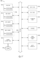
- FIG. 11 illustrates generally an example of a block diagram of a machine 1100 upon which any one or more of the techniques (e.g., methodologies) discussed herein may perform in accordance with some embodiments.
- the machine 1100 may operate as a standalone device or may be connected (e.g., networked) to other machines.
- the machine 1100 may be a printer in which the system described above is included, or a part or component of the printer, a component operably connected to the printer, or the like.
- the machine 1100 may also be a personal computer (PC), a tablet PC, a control system, a mobile telephone, a web appliance, a network router, switch or bridge, or any machine capable of executing instructions (sequential or otherwise) that specify actions to be taken by that machine.
- PC personal computer
- tablet PC tablet PC
- control system a mobile telephone
- web appliance web appliance
- network router switch or bridge
- machine any machine capable of executing instructions (sequential or otherwise) that specify actions to be taken by that machine.
- machine shall also be taken to include any collection of machines that individually or jointly execute a set (or multiple sets) of instructions to perform any one or more of the methodologies discussed herein.
- Examples, as described herein, may include, or may operate on, logic or a number of components, modules, or mechanisms.
- Modules are tangible entities (e.g., hardware) capable of performing specified operations when operating.
- a module includes hardware.
- the hardware may be specifically configured to carry out a specific operation (e.g., hardwired).
- the hardware may include configurable execution units (e.g., transistors, circuits, etc.) and a computer readable medium containing instructions, where the instructions configure the execution units to carry out a specific operation when in operation. The configuring may occur under the direction of the execution's units or a loading mechanism. Accordingly, the execution units are communicatively coupled to the computer readable medium when the device is operating.
- the execution units may be a member of more than one module.
- the execution units may be configured by a first set of instructions to implement a first module at one point in time and reconfigured by a second set of instructions to implement a second module.
- Machine 1100 may include a hardware processor 1102 (e.g., a central processing unit (CPU), a graphics processing unit (GPU), a hardware processor core, or any combination thereof), a main memory 1104 and a static memory 1106, some or all of which may communicate with each other via an interlink (e.g., bus) 1130.
- the machine 1100 may further include a display unit 1110, an alphanumeric input device 1112 and a user interface (UI) navigation device 1114.
- the display unit 1110, alphanumeric input device 1112 and UI navigation device 1114 may be a touch screen display.
- the machine 1100 may additionally include a storage device (e.g., drive unit) 1108, a signal generation device 1118 (e.g., a speaker), a network interface device 1120, and one or more sensors 1116, such as a global positioning system (GPS) sensor, accelerometer, or another sensor.
- the machine 1100 may include an output controller 1128, such as a serial (e.g., universal serial bus (USB), parallel, or other wired or wireless (e.g., infrared (IR), near field communication (NFC), etc.) connection to communicate or control one or more peripheral devices (e.g., a printer, a card reader, etc.).
- a serial e.g., universal serial bus (USB), parallel, or other wired or wireless (e.g., infrared (IR), near field communication (NFC), etc.) connection to communicate or control one or more peripheral devices (e.g., a printer, a card reader, etc.).
- USB universal serial bus
- NFC near
- the storage device 1108 may include a machine readable medium 1122 that is non-transitory on which is stored one or more sets of data structures or instructions 1124 (e.g., software) embodying or utilized by any one or more of the techniques or functions described herein.
- the instructions 1124 may also reside, completely or at least partially, within the main memory 1104, within static memory 1106, or within the hardware processor 1102 during execution thereof by the machine 1100.
- one or any combination of the hardware processor 1102, the main memory 1104, the static memory 1106, or the storage device 1108 may constitute machine readable media.
- machine readable medium 1122 is illustrated as a single medium, the term “machine readable medium” may include a single medium or multiple media (e.g., a centralized or distributed database, or associated caches and servers) configured to store the one or more instructions 1124.
- machine readable medium may include a single medium or multiple media (e.g., a centralized or distributed database, or associated caches and servers) configured to store the one or more instructions 1124.
- machine readable medium may include any non-transitory medium that is capable of storing, encoding, or carrying instructions for execution by the machine 1100 and that cause the machine 1100 to perform any one or more of the techniques of the present disclosure, or that is capable of storing, encoding or carrying data structures used by or associated with such instructions.
- Non-limiting machine-readable medium examples may include solid-state memories, and optical and magnetic media.
- machine-readable media may include: non-volatile memory, such as semiconductor memory devices (e.g., Electrically Programmable Read-Only Memory (EPROM), Electrically Erasable Programmable Read-Only Memory (EEPROM)) and flash memory devices; magnetic disks, such as internal hard disks and removable disks; magneto-optical disks; and CD-ROM and DVD-ROM disks.
- non-volatile memory such as semiconductor memory devices (e.g., Electrically Programmable Read-Only Memory (EPROM), Electrically Erasable Programmable Read-Only Memory (EEPROM)) and flash memory devices
- EPROM Electrically Programmable Read-Only Memory
- EEPROM Electrically Erasable Programmable Read-Only Memory
- flash memory devices e.g., Electrically Erasable Programmable Read-Only Memory (EEPROM)
- EPROM Electrically Programmable Read-Only Memory
- EEPROM Electrically Erasable Programmable Read-Only Memory
- flash memory devices e.g., Electrically Era
- the instructions 1124 may further be transmitted or received over a communications network 1126 using a transmission medium via the network interface device 1120 utilizing any one of a number of transfer protocols (e.g., frame relay, internet protocol (IP), transmission control protocol (TCP), user datagram protocol (UDP), hypertext transfer protocol (HTTP), etc.).
- transfer protocols e.g., frame relay, internet protocol (IP), transmission control protocol (TCP), user datagram protocol (UDP), hypertext transfer protocol (HTTP), etc.
- Example communication networks may include a local area network (LAN), a wide area network (WAN), a packet data network (e.g., the Internet), mobile telephone networks (e.g., cellular networks), Plain Old Telephone (POTS) networks, and wireless data networks (e.g., Institute of Electrical and Electronics Engineers (IEEE) 802.11 family of standards known as Wi-Fi ® , IEEE 802.16 family of standards known as WiMax ® ), IEEE 802.15.4 family of standards, peer-to-peer (P2P) networks, among others.
- the network interface device 1120 may include one or more physical jacks (e.g., Ethernet, coaxial, or phone jacks) or one or more antennas to connect to the communications network 1126.
- the network interface device 1120 may include a plurality of antennas to wirelessly communicate using at least one of single-input multiple-output (SIMO), multiple-input multiple-output (MIMO), or multiple-input single-output (MISO) techniques.
- SIMO single-input multiple-output
- MIMO multiple-input multiple-output
- MISO multiple-input single-output
- transmission medium shall be taken to include any intangible medium that is capable of storing, encoding or carrying instructions for execution by the machine 1100, and includes digital or analog communications signals or other intangible medium to facilitate communication of such software.
- the terms “substantially” or “generally” refer to the complete or nearly complete extent or degree of an action, characteristic, property, state, structure, item, or result.
- an object that is “substantially” or “generally” enclosed would mean that the object is either completely enclosed or nearly completely enclosed.
- the exact allowable degree of deviation from absolute completeness may in some cases depend on the specific context. However, generally speaking, the nearness of completion will be so as to have generally the same overall result as if absolute and total completion were obtained.
- the use of “substantially” or “generally” is equally applicable when used in a negative connotation to refer to the complete or near complete lack of an action, characteristic, property, state, structure, item, or result.
- an element, combination, embodiment, or composition that is "substantially free of” or “generally free of” an element may still actually contain such element as long as there is generally no significant effect thereof.
Landscapes
- Ink Jet (AREA)
Claims (10)
- Verfahren zur Verbesserung des Tintenstrahldüsenzustands und der Druckzuverlässigkeit eines Tintenstrahldruckers, umfassend:Überwachen, ob ein Auslöseereignis eingetreten ist, wobei das Auslöseereignis eine verstrichene Zeitperiode umfasst, wobei die verstrichene Zeitperiode eine Zeitspanne ist, seit der ein Teil der in einem Vorlauftank (200, 202) enthaltenen Tinte zuvor vom Vorlauftank (200, 202) in eine Richtung zur Tintenkartusche (112) gepumpt wurde, und/oder die verstrichene Zeitperiode eine Zeitspanne ist, seit der die Tintenkartusche (112) manuell bewegt wurde;Pumpen, als Reaktion auf ein Erfassen, dass das Auslöseereignis eingetreten ist, von mindestens einem Teil der im Vorlauftank (200, 202) enthaltenen Tinte vom Vorlauftank (200, 202) in eine Richtung zur Tintenkartusche (112) durch ein Rohr (116), das den Vorlauftank (200, 202) und die Tintenkartusche (112) verbindet, wobei der Vorlauftank (200, 202) in einem Tastkopf (102) enthalten und mit einem Druckkopf (300, 302, 304) verbunden ist; undUmwälzen der Tinte durch das Rohr (116) zurück in eine Richtung zum Vorlauftank (200, 202).
- Verfahren nach Anspruch 1, darüber hinaus umfassend:
Bewegen des Tastkopfs (102), wobei das Bewegen des Tastkopfs (102) umfasst, den Tastkopf (102) sich in mindestens eine der folgenden Richtungen bewegen zu lassen: eine Richtung von links nach rechts, eine Richtung von rechts nach links, eine Richtung von hinten nach vorne oder eine Richtung von vorne nach hinten entlang eines x-y-Portals. - Verfahren nach einem der Ansprüche 1-2, darüber hinaus umfassend:
Verwenden eines Füllstandsensors, der im Vorlauftank (200, 202) enthalten ist, um einen Füllstand der Tinte im Vorlauftank (200, 202) zu überwachen. - Verfahren nach Anspruch 1, wobei die Zeitspanne, seit der die Tintenkartusche (112) manuell bewegt wurde, eine Zeitspanne umfasst, seit der die Tintenkartusche (112) aus einem Tintenkartuschenträger entfernt wurde, und/oder eine Zeitspanne, seit der ein Benutzer über eine Benutzerschnittstelle angezeigt hat, dass die Tintenkartusche (112) manuell bewegt wurde.
- Verfahren nach einem der Ansprüche 1-3, wobei das Auslöseereignis darüber hinaus mindestens einen der folgenden Vorgänge umfasst: eine manuelle Aktivierung einer automatischen Bewegungsroutine, ein Austausch der Tintenkartusche (112) oder eine Erfassung, durch einen Sensor, einer Verstopfung im Druckkopf (300, 302, 304) und/oder in einer Druckdüse am Druckkopf (300, 302, 304) und/oder im Rohr (116).
- Verfahren nach jedem vorhergehenden Anspruch, wobei der Drucker als Reaktion darauf in einen gesperrten Zustand eintritt, dass erfasst wird, dass das Auslöseereignis eingetreten ist, und wobei der gesperrte Zustand den Drucker daran hindert, einen neuen Druckauftrag zu drucken.
- Verfahren nach Anspruch 1, wobei der Druckkopf (300, 302, 304) eine Düsenplatte aufweist, und wobei die Düsenplatte (400) eine Reihe von Düsen (402, 404) aufweist, wobei die Reihe von Düsen (402, 404) eine Vielzahl von Düsen enthält;
wobei das Verfahren darüber hinaus umfasst:Verschieben des Tastkopfs (102) zu einer Wartungsstation, wobei die Wartungsstation eine Spülkappe (502) aufweist;Erzeugen von mindestens einer teilweisen Abdichtung zwischen der Spülkappe (502) und mindestens einem der folgenden Elemente: einer bestimmten Düse aus der Vielzahl von Düsen, der Reihe von Düsen (402, 404), der Düsenplatte (400) oder dem Druckkopf (300, 302, 304); undDurchführen einer Umkehrspülung an mindestens einem der folgenden Elemente: einer bestimmten Düse aus der Vielzahl von Düsen, der Reihe von Düsen (402, 404), der Düsenplatte (400) oder dem Druckkopf (300, 302, 304), wobei die Umkehrspülung umfasst, unter Verwendung einer Vakuumpumpe (600), die mit der Spülkappe (502) funktionsmäßig verbunden ist, einen Überdruck anzulegen. - Verfahren nach Anspruch 7, wobei die Wartungsstation darüber hinaus einen Abstreifer (504) aufweist und das Verfahren darüber hinaus umfasst:Ausstoßen einer Menge an Tinte aus dem Druckkopf (300, 302, 304) auf eine Düsenplatte (400);Abstreifen der Düsenplatte (400) mit dem Abstreifer (504) im Wesentlichen gleichzeitig mit dem Ausstoßen der Menge an Tinte; undoptional den Abstreifer (504) von überschüssiger Tinte zu reinigen, und zwar durch Drehen des Abstreifers (504) um eine Achse.
- Verfahren nach einem der Ansprüche 7-8, wobei durch die Umkehrspülung bewirkt wird, dass mindestens ein Teil der Tinte, die sich in mindestens einer Düse aus der Vielzahl von Düsen befindet, durch die mindestens eine Düse aus der Vielzahl von Düsen in eine Richtung zum Vorlauftank (200, 202) gedrückt wird.
- Verfahren nach einem der Ansprüche 7-9, darüber hinaus umfassend:
Umkehren des Betriebs der Vakuumpumpe (600), um zu bewirken, dass die Vakuumpumpe (600) über die Spülkappe (502) einen Unterdruck an mindestens eines der folgenden Elemente anlegt: die bestimmte Düse aus der Vielzahl von Düsen, die Reihe von Düsen (402, 404), die Düsenplatte (400) oder den Druckkopf (300, 302, 304).
Priority Applications (2)
| Application Number | Priority Date | Filing Date | Title |
|---|---|---|---|
| EP23151674.1A EP4190570B1 (de) | 2020-09-14 | 2021-06-25 | Tintenstrahldüsengesundheit und druckzuverlässigkeit |
| EP23151675.8A EP4190571B1 (de) | 2020-09-14 | 2021-06-25 | Tintenstrahldüsengesundheit und druckzuverlässigkeit |
Applications Claiming Priority (2)
| Application Number | Priority Date | Filing Date | Title |
|---|---|---|---|
| US202063078285P | 2020-09-14 | 2020-09-14 | |
| US17/090,238 US11969994B2 (en) | 2020-09-14 | 2020-11-05 | Ink jet nozzle health and printing reliability |
Related Child Applications (4)
| Application Number | Title | Priority Date | Filing Date |
|---|---|---|---|
| EP23151675.8A Division-Into EP4190571B1 (de) | 2020-09-14 | 2021-06-25 | Tintenstrahldüsengesundheit und druckzuverlässigkeit |
| EP23151675.8A Division EP4190571B1 (de) | 2020-09-14 | 2021-06-25 | Tintenstrahldüsengesundheit und druckzuverlässigkeit |
| EP23151674.1A Division-Into EP4190570B1 (de) | 2020-09-14 | 2021-06-25 | Tintenstrahldüsengesundheit und druckzuverlässigkeit |
| EP23151674.1A Division EP4190570B1 (de) | 2020-09-14 | 2021-06-25 | Tintenstrahldüsengesundheit und druckzuverlässigkeit |
Publications (3)
| Publication Number | Publication Date |
|---|---|
| EP3967501A2 EP3967501A2 (de) | 2022-03-16 |
| EP3967501A3 EP3967501A3 (de) | 2022-05-11 |
| EP3967501B1 true EP3967501B1 (de) | 2023-10-04 |
Family
ID=76623952
Family Applications (3)
| Application Number | Title | Priority Date | Filing Date |
|---|---|---|---|
| EP23151674.1A Active EP4190570B1 (de) | 2020-09-14 | 2021-06-25 | Tintenstrahldüsengesundheit und druckzuverlässigkeit |
| EP21181753.1A Active EP3967501B1 (de) | 2020-09-14 | 2021-06-25 | Tintenstrahldüsengesundheits- und -druckzuverlässigkeit |
| EP23151675.8A Active EP4190571B1 (de) | 2020-09-14 | 2021-06-25 | Tintenstrahldüsengesundheit und druckzuverlässigkeit |
Family Applications Before (1)
| Application Number | Title | Priority Date | Filing Date |
|---|---|---|---|
| EP23151674.1A Active EP4190570B1 (de) | 2020-09-14 | 2021-06-25 | Tintenstrahldüsengesundheit und druckzuverlässigkeit |
Family Applications After (1)
| Application Number | Title | Priority Date | Filing Date |
|---|---|---|---|
| EP23151675.8A Active EP4190571B1 (de) | 2020-09-14 | 2021-06-25 | Tintenstrahldüsengesundheit und druckzuverlässigkeit |
Country Status (3)
| Country | Link |
|---|---|
| US (3) | US11969994B2 (de) |
| EP (3) | EP4190570B1 (de) |
| CN (2) | CN114179508B (de) |
Families Citing this family (1)
| Publication number | Priority date | Publication date | Assignee | Title |
|---|---|---|---|---|
| US11969994B2 (en) | 2020-09-14 | 2024-04-30 | Assa Abloy Ab | Ink jet nozzle health and printing reliability |
Family Cites Families (28)
| Publication number | Priority date | Publication date | Assignee | Title |
|---|---|---|---|---|
| JP3233175B2 (ja) * | 1993-03-11 | 2001-11-26 | セイコーエプソン株式会社 | インクジェット式記録装置 |
| JP3726414B2 (ja) | 1997-04-03 | 2005-12-14 | ブラザー工業株式会社 | インクジェット記録装置 |
| JP3846083B2 (ja) | 1998-02-06 | 2006-11-15 | ブラザー工業株式会社 | インクジェット記録装置 |
| US6609780B2 (en) | 2001-07-06 | 2003-08-26 | Brother Kogyo Kabushiki Kaisha | Ink jet printer having a mechanism for driving wiper and purge pump |
| JP3903030B2 (ja) * | 2003-09-09 | 2007-04-11 | 松下電器産業株式会社 | インクジェット式記録システム |
| JP4543952B2 (ja) * | 2004-11-17 | 2010-09-15 | ブラザー工業株式会社 | インクジェットヘッド |
| US7717540B1 (en) | 2006-04-04 | 2010-05-18 | Hewlett-Packard Development Company, L.P. | Clog detection and clearing method for ink delivery system |
| JP4895723B2 (ja) * | 2006-08-23 | 2012-03-14 | 富士フイルム株式会社 | 液体吐出装置および液体吐出面の清掃方法 |
| JP4861129B2 (ja) * | 2006-11-08 | 2012-01-25 | 株式会社ミヤコシ | プリントヘッドのワイピング装置 |
| JP5067876B2 (ja) * | 2008-04-21 | 2012-11-07 | キヤノン株式会社 | インクジェット記録装置 |
| JP4535181B2 (ja) * | 2008-08-26 | 2010-09-01 | ブラザー工業株式会社 | 液体吐出装置の制御方法、及び、液体吐出装置 |
| JP5376300B2 (ja) * | 2008-12-03 | 2013-12-25 | 株式会社リコー | インクジェット記録装置 |
| JP5656395B2 (ja) * | 2009-12-01 | 2015-01-21 | キヤノン株式会社 | インクジェット記録装置 |
| JP5601075B2 (ja) * | 2010-08-04 | 2014-10-08 | 株式会社リコー | インクジェット用インク、並びにインクカートリッジ、インクジェット記録方法、インクジェット記録装置及びインク記録物 |
| JP5664023B2 (ja) | 2010-08-27 | 2015-02-04 | セイコーエプソン株式会社 | 画像形成装置 |
| JP5874898B2 (ja) * | 2010-12-17 | 2016-03-02 | 株式会社リコー | 画像形成装置 |
| US9539815B2 (en) | 2011-06-20 | 2017-01-10 | Hewlett-Packard Development Company, L.P. | Low-profile service stations for use with printers |
| EP2991833B1 (de) * | 2013-05-03 | 2021-04-14 | Canon Production Printing Netherlands B.V. | Druckkopfmontieranordnung |
| CN104417067A (zh) * | 2013-09-11 | 2015-03-18 | 北大方正集团有限公司 | 一种喷墨打印机喷头的清洗装置 |
| US9757941B2 (en) | 2014-04-29 | 2017-09-12 | Hewlett-Packard Development Company, L.P. | Image content based spit bars |
| JP6477523B2 (ja) * | 2016-01-26 | 2019-03-06 | ブラザー工業株式会社 | 印刷装置及びコンピュータプログラム |
| US20180345682A1 (en) * | 2017-05-30 | 2018-12-06 | Océ Holding B.V. | Printer and method for operating a printer |
| DE102017215475A1 (de) | 2017-09-04 | 2019-03-07 | Krones Ag | Direktdruckmaschine und -verfahren zur Bedruckung von Behältern mit einem Direktdruck |
| JP7040036B2 (ja) * | 2018-01-19 | 2022-03-23 | 株式会社リコー | 液体吐出ユニットと画像形成装置 |
| JP7317937B2 (ja) * | 2018-07-20 | 2023-07-31 | ナノ ディメンション テクノロジーズ,リミテッド | インクジェット印刷ヘッドの非接触メンテナンス |
| JP7275604B2 (ja) | 2019-01-31 | 2023-05-18 | 株式会社リコー | 移動体、液体を吐出する装置 |
| JP7452061B2 (ja) | 2019-02-18 | 2024-03-19 | 京セラドキュメントソリューションズ株式会社 | インクジェット記録装置 |
| US11969994B2 (en) | 2020-09-14 | 2024-04-30 | Assa Abloy Ab | Ink jet nozzle health and printing reliability |
-
2020
- 2020-11-05 US US17/090,238 patent/US11969994B2/en active Active
-
2021
- 2021-06-23 CN CN202110700194.6A patent/CN114179508B/zh active Active
- 2021-06-23 CN CN202310699610.4A patent/CN116674292A/zh active Pending
- 2021-06-25 EP EP23151674.1A patent/EP4190570B1/de active Active
- 2021-06-25 EP EP21181753.1A patent/EP3967501B1/de active Active
- 2021-06-25 EP EP23151675.8A patent/EP4190571B1/de active Active
-
2024
- 2024-02-15 US US18/442,323 patent/US20240181769A1/en active Pending
- 2024-02-15 US US18/442,342 patent/US20240181770A1/en active Pending
Also Published As
| Publication number | Publication date |
|---|---|
| CN114179508B (zh) | 2023-07-18 |
| US20220080722A1 (en) | 2022-03-17 |
| CN114179508A (zh) | 2022-03-15 |
| EP3967501A3 (de) | 2022-05-11 |
| EP4190571A1 (de) | 2023-06-07 |
| EP4190570A1 (de) | 2023-06-07 |
| US20240181769A1 (en) | 2024-06-06 |
| US20240181770A1 (en) | 2024-06-06 |
| EP4190570B1 (de) | 2024-10-02 |
| EP4190571B1 (de) | 2024-10-02 |
| EP3967501A2 (de) | 2022-03-16 |
| US11969994B2 (en) | 2024-04-30 |
| CN116674292A (zh) | 2023-09-01 |
Similar Documents
| Publication | Publication Date | Title |
|---|---|---|
| JP6253470B2 (ja) | ヘッド洗浄装置、インクジェットプリンターおよびヘッド洗浄方法 | |
| CN103358695B (zh) | 喷墨记录装置以及用于控制喷墨记录装置的方法 | |
| US8794737B2 (en) | Inkjet printing apparatus and control method for restore unit | |
| US20240181770A1 (en) | Ink jet nozzle health and printing reliability | |
| JP6329858B2 (ja) | インクジェットヘッド装置及び画像形成装置 | |
| JP2007216426A (ja) | 液体噴射装置及び液体噴射ヘッドのメンテナンス方法 | |
| JP6150537B2 (ja) | インクジェット記録装置および、記録ヘッドの払拭方法 | |
| JP6299330B2 (ja) | 液体吐出装置 | |
| JP7222298B2 (ja) | インク吐出ヘッドのメンテナンス装置、インクジェット記録装置及びインク吐出ヘッドのメンテナンス方法 | |
| EP3521040B1 (de) | Flüssigkeitsausstossvorrichtung | |
| CN110091605B (zh) | 液体喷出装置 | |
| JP4630558B2 (ja) | 記録装置及び回復制御方法 | |
| JP4850670B2 (ja) | 記録装置 | |
| CN114851728A (zh) | 印刷系统以及印刷装置 | |
| JP2008023889A (ja) | 液体噴射装置 | |
| JP2012162010A (ja) | 液体噴射装置および液体噴射装置におけるフラッシング方法 | |
| JP7388094B2 (ja) | インク吐出ヘッドのメンテナンス装置、インクジェット記録装置及びインク吐出ヘッドのメンテナンス方法 | |
| JP2020011398A (ja) | インクジェットプリンタ | |
| JP2006224612A (ja) | インクジェット記録装置 | |
| JP2007216496A (ja) | インクジェット方式画像形成装置 | |
| JP2006224359A (ja) | 液体噴射装置および液体噴射装置の吐出能力回復方法 | |
| JP2020082538A (ja) | インクジェット記録装置および記録ヘッドのノズル形成面の清浄方法 | |
| JP2018020446A (ja) | インクジェット記録装置及びクリーニング方法 | |
| JP2007152661A (ja) | クリーニング方法 | |
| JP2010131948A (ja) | 流体噴射装置、流体の拭き取り方法、及び、拭き取り装置 |
Legal Events
| Date | Code | Title | Description |
|---|---|---|---|
| PUAI | Public reference made under article 153(3) epc to a published international application that has entered the european phase |
Free format text: ORIGINAL CODE: 0009012 |
|
| STAA | Information on the status of an ep patent application or granted ep patent |
Free format text: STATUS: THE APPLICATION HAS BEEN PUBLISHED |
|
| AK | Designated contracting states |
Kind code of ref document: A2 Designated state(s): AL AT BE BG CH CY CZ DE DK EE ES FI FR GB GR HR HU IE IS IT LI LT LU LV MC MK MT NL NO PL PT RO RS SE SI SK SM TR |
|
| PUAL | Search report despatched |
Free format text: ORIGINAL CODE: 0009013 |
|
| AK | Designated contracting states |
Kind code of ref document: A3 Designated state(s): AL AT BE BG CH CY CZ DE DK EE ES FI FR GB GR HR HU IE IS IT LI LT LU LV MC MK MT NL NO PL PT RO RS SE SI SK SM TR |
|
| RIC1 | Information provided on ipc code assigned before grant |
Ipc: B41J 2/165 20060101ALI20220407BHEP Ipc: B41J 2/175 20060101ALI20220407BHEP Ipc: B41J 2/17 20060101AFI20220407BHEP |
|
| STAA | Information on the status of an ep patent application or granted ep patent |
Free format text: STATUS: REQUEST FOR EXAMINATION WAS MADE |
|
| 17P | Request for examination filed |
Effective date: 20221108 |
|
| RBV | Designated contracting states (corrected) |
Designated state(s): AL AT BE BG CH CY CZ DE DK EE ES FI FR GB GR HR HU IE IS IT LI LT LU LV MC MK MT NL NO PL PT RO RS SE SI SK SM TR |
|
| GRAP | Despatch of communication of intention to grant a patent |
Free format text: ORIGINAL CODE: EPIDOSNIGR1 |
|
| STAA | Information on the status of an ep patent application or granted ep patent |
Free format text: STATUS: GRANT OF PATENT IS INTENDED |
|
| GRAJ | Information related to disapproval of communication of intention to grant by the applicant or resumption of examination proceedings by the epo deleted |
Free format text: ORIGINAL CODE: EPIDOSDIGR1 |
|
| INTG | Intention to grant announced |
Effective date: 20230519 |
|
| STAA | Information on the status of an ep patent application or granted ep patent |
Free format text: STATUS: REQUEST FOR EXAMINATION WAS MADE |
|
| GRAP | Despatch of communication of intention to grant a patent |
Free format text: ORIGINAL CODE: EPIDOSNIGR1 |
|
| STAA | Information on the status of an ep patent application or granted ep patent |
Free format text: STATUS: GRANT OF PATENT IS INTENDED |
|
| INTC | Intention to grant announced (deleted) | ||
| INTG | Intention to grant announced |
Effective date: 20230705 |
|
| P01 | Opt-out of the competence of the unified patent court (upc) registered |
Effective date: 20230627 |
|
| GRAS | Grant fee paid |
Free format text: ORIGINAL CODE: EPIDOSNIGR3 |
|
| GRAA | (expected) grant |
Free format text: ORIGINAL CODE: 0009210 |
|
| STAA | Information on the status of an ep patent application or granted ep patent |
Free format text: STATUS: THE PATENT HAS BEEN GRANTED |
|
| RIN1 | Information on inventor provided before grant (corrected) |
Inventor name: SNYDER, TANYA JEGERIS Inventor name: ELEMINO, KYRSTEN DOMINIQUE Inventor name: O'HARA, BRADLEY Inventor name: BEERY, CHAD EVERETT Inventor name: PASTOR, EVAN Inventor name: LIEN, BRENT D. |
|
| AK | Designated contracting states |
Kind code of ref document: B1 Designated state(s): AL AT BE BG CH CY CZ DE DK EE ES FI FR GB GR HR HU IE IS IT LI LT LU LV MC MK MT NL NO PL PT RO RS SE SI SK SM TR |
|
| REG | Reference to a national code |
Ref country code: GB Ref legal event code: FG4D |
|
| REG | Reference to a national code |
Ref country code: CH Ref legal event code: EP |
|
| REG | Reference to a national code |
Ref country code: IE Ref legal event code: FG4D |
|
| REG | Reference to a national code |
Ref country code: DE Ref legal event code: R096 Ref document number: 602021005560 Country of ref document: DE |
|
| REG | Reference to a national code |
Ref country code: LT Ref legal event code: MG9D |
|
| REG | Reference to a national code |
Ref country code: NL Ref legal event code: MP Effective date: 20231004 |
|
| REG | Reference to a national code |
Ref country code: AT Ref legal event code: MK05 Ref document number: 1617365 Country of ref document: AT Kind code of ref document: T Effective date: 20231004 |
|
| PG25 | Lapsed in a contracting state [announced via postgrant information from national office to epo] |
Ref country code: NL Free format text: LAPSE BECAUSE OF FAILURE TO SUBMIT A TRANSLATION OF THE DESCRIPTION OR TO PAY THE FEE WITHIN THE PRESCRIBED TIME-LIMIT Effective date: 20231004 |
|
| PG25 | Lapsed in a contracting state [announced via postgrant information from national office to epo] |
Ref country code: GR Free format text: LAPSE BECAUSE OF FAILURE TO SUBMIT A TRANSLATION OF THE DESCRIPTION OR TO PAY THE FEE WITHIN THE PRESCRIBED TIME-LIMIT Effective date: 20240105 |
|
| PG25 | Lapsed in a contracting state [announced via postgrant information from national office to epo] |
Ref country code: IS Free format text: LAPSE BECAUSE OF FAILURE TO SUBMIT A TRANSLATION OF THE DESCRIPTION OR TO PAY THE FEE WITHIN THE PRESCRIBED TIME-LIMIT Effective date: 20240204 |
|
| PG25 | Lapsed in a contracting state [announced via postgrant information from national office to epo] |
Ref country code: LT Free format text: LAPSE BECAUSE OF FAILURE TO SUBMIT A TRANSLATION OF THE DESCRIPTION OR TO PAY THE FEE WITHIN THE PRESCRIBED TIME-LIMIT Effective date: 20231004 |
|
| PG25 | Lapsed in a contracting state [announced via postgrant information from national office to epo] |
Ref country code: AT Free format text: LAPSE BECAUSE OF FAILURE TO SUBMIT A TRANSLATION OF THE DESCRIPTION OR TO PAY THE FEE WITHIN THE PRESCRIBED TIME-LIMIT Effective date: 20231004 |
|
| PG25 | Lapsed in a contracting state [announced via postgrant information from national office to epo] |
Ref country code: ES Free format text: LAPSE BECAUSE OF FAILURE TO SUBMIT A TRANSLATION OF THE DESCRIPTION OR TO PAY THE FEE WITHIN THE PRESCRIBED TIME-LIMIT Effective date: 20231004 |
|
| PG25 | Lapsed in a contracting state [announced via postgrant information from national office to epo] |
Ref country code: LT Free format text: LAPSE BECAUSE OF FAILURE TO SUBMIT A TRANSLATION OF THE DESCRIPTION OR TO PAY THE FEE WITHIN THE PRESCRIBED TIME-LIMIT Effective date: 20231004 Ref country code: IS Free format text: LAPSE BECAUSE OF FAILURE TO SUBMIT A TRANSLATION OF THE DESCRIPTION OR TO PAY THE FEE WITHIN THE PRESCRIBED TIME-LIMIT Effective date: 20240204 Ref country code: GR Free format text: LAPSE BECAUSE OF FAILURE TO SUBMIT A TRANSLATION OF THE DESCRIPTION OR TO PAY THE FEE WITHIN THE PRESCRIBED TIME-LIMIT Effective date: 20240105 Ref country code: ES Free format text: LAPSE BECAUSE OF FAILURE TO SUBMIT A TRANSLATION OF THE DESCRIPTION OR TO PAY THE FEE WITHIN THE PRESCRIBED TIME-LIMIT Effective date: 20231004 Ref country code: BG Free format text: LAPSE BECAUSE OF FAILURE TO SUBMIT A TRANSLATION OF THE DESCRIPTION OR TO PAY THE FEE WITHIN THE PRESCRIBED TIME-LIMIT Effective date: 20240104 Ref country code: AT Free format text: LAPSE BECAUSE OF FAILURE TO SUBMIT A TRANSLATION OF THE DESCRIPTION OR TO PAY THE FEE WITHIN THE PRESCRIBED TIME-LIMIT Effective date: 20231004 Ref country code: PT Free format text: LAPSE BECAUSE OF FAILURE TO SUBMIT A TRANSLATION OF THE DESCRIPTION OR TO PAY THE FEE WITHIN THE PRESCRIBED TIME-LIMIT Effective date: 20240205 |
|
| PG25 | Lapsed in a contracting state [announced via postgrant information from national office to epo] |
Ref country code: SE Free format text: LAPSE BECAUSE OF FAILURE TO SUBMIT A TRANSLATION OF THE DESCRIPTION OR TO PAY THE FEE WITHIN THE PRESCRIBED TIME-LIMIT Effective date: 20231004 Ref country code: RS Free format text: LAPSE BECAUSE OF FAILURE TO SUBMIT A TRANSLATION OF THE DESCRIPTION OR TO PAY THE FEE WITHIN THE PRESCRIBED TIME-LIMIT Effective date: 20231004 Ref country code: PL Free format text: LAPSE BECAUSE OF FAILURE TO SUBMIT A TRANSLATION OF THE DESCRIPTION OR TO PAY THE FEE WITHIN THE PRESCRIBED TIME-LIMIT Effective date: 20231004 Ref country code: NO Free format text: LAPSE BECAUSE OF FAILURE TO SUBMIT A TRANSLATION OF THE DESCRIPTION OR TO PAY THE FEE WITHIN THE PRESCRIBED TIME-LIMIT Effective date: 20240104 Ref country code: LV Free format text: LAPSE BECAUSE OF FAILURE TO SUBMIT A TRANSLATION OF THE DESCRIPTION OR TO PAY THE FEE WITHIN THE PRESCRIBED TIME-LIMIT Effective date: 20231004 Ref country code: HR Free format text: LAPSE BECAUSE OF FAILURE TO SUBMIT A TRANSLATION OF THE DESCRIPTION OR TO PAY THE FEE WITHIN THE PRESCRIBED TIME-LIMIT Effective date: 20231004 |
|
| REG | Reference to a national code |
Ref country code: DE Ref legal event code: R097 Ref document number: 602021005560 Country of ref document: DE |
|
| PG25 | Lapsed in a contracting state [announced via postgrant information from national office to epo] |
Ref country code: DK Free format text: LAPSE BECAUSE OF FAILURE TO SUBMIT A TRANSLATION OF THE DESCRIPTION OR TO PAY THE FEE WITHIN THE PRESCRIBED TIME-LIMIT Effective date: 20231004 |
|
| PG25 | Lapsed in a contracting state [announced via postgrant information from national office to epo] |
Ref country code: CZ Free format text: LAPSE BECAUSE OF FAILURE TO SUBMIT A TRANSLATION OF THE DESCRIPTION OR TO PAY THE FEE WITHIN THE PRESCRIBED TIME-LIMIT Effective date: 20231004 |
|
| PG25 | Lapsed in a contracting state [announced via postgrant information from national office to epo] |
Ref country code: SK Free format text: LAPSE BECAUSE OF FAILURE TO SUBMIT A TRANSLATION OF THE DESCRIPTION OR TO PAY THE FEE WITHIN THE PRESCRIBED TIME-LIMIT Effective date: 20231004 |
|
| PG25 | Lapsed in a contracting state [announced via postgrant information from national office to epo] |
Ref country code: SM Free format text: LAPSE BECAUSE OF FAILURE TO SUBMIT A TRANSLATION OF THE DESCRIPTION OR TO PAY THE FEE WITHIN THE PRESCRIBED TIME-LIMIT Effective date: 20231004 Ref country code: SK Free format text: LAPSE BECAUSE OF FAILURE TO SUBMIT A TRANSLATION OF THE DESCRIPTION OR TO PAY THE FEE WITHIN THE PRESCRIBED TIME-LIMIT Effective date: 20231004 Ref country code: RO Free format text: LAPSE BECAUSE OF FAILURE TO SUBMIT A TRANSLATION OF THE DESCRIPTION OR TO PAY THE FEE WITHIN THE PRESCRIBED TIME-LIMIT Effective date: 20231004 Ref country code: IT Free format text: LAPSE BECAUSE OF FAILURE TO SUBMIT A TRANSLATION OF THE DESCRIPTION OR TO PAY THE FEE WITHIN THE PRESCRIBED TIME-LIMIT Effective date: 20231004 Ref country code: EE Free format text: LAPSE BECAUSE OF FAILURE TO SUBMIT A TRANSLATION OF THE DESCRIPTION OR TO PAY THE FEE WITHIN THE PRESCRIBED TIME-LIMIT Effective date: 20231004 Ref country code: DK Free format text: LAPSE BECAUSE OF FAILURE TO SUBMIT A TRANSLATION OF THE DESCRIPTION OR TO PAY THE FEE WITHIN THE PRESCRIBED TIME-LIMIT Effective date: 20231004 Ref country code: CZ Free format text: LAPSE BECAUSE OF FAILURE TO SUBMIT A TRANSLATION OF THE DESCRIPTION OR TO PAY THE FEE WITHIN THE PRESCRIBED TIME-LIMIT Effective date: 20231004 |
|
| PLBE | No opposition filed within time limit |
Free format text: ORIGINAL CODE: 0009261 |
|
| STAA | Information on the status of an ep patent application or granted ep patent |
Free format text: STATUS: NO OPPOSITION FILED WITHIN TIME LIMIT |
|
| 26N | No opposition filed |
Effective date: 20240705 |
|
| PG25 | Lapsed in a contracting state [announced via postgrant information from national office to epo] |
Ref country code: SI Free format text: LAPSE BECAUSE OF FAILURE TO SUBMIT A TRANSLATION OF THE DESCRIPTION OR TO PAY THE FEE WITHIN THE PRESCRIBED TIME-LIMIT Effective date: 20231004 |
|
| PG25 | Lapsed in a contracting state [announced via postgrant information from national office to epo] |
Ref country code: SI Free format text: LAPSE BECAUSE OF FAILURE TO SUBMIT A TRANSLATION OF THE DESCRIPTION OR TO PAY THE FEE WITHIN THE PRESCRIBED TIME-LIMIT Effective date: 20231004 |
|
| PG25 | Lapsed in a contracting state [announced via postgrant information from national office to epo] |
Ref country code: MC Free format text: LAPSE BECAUSE OF FAILURE TO SUBMIT A TRANSLATION OF THE DESCRIPTION OR TO PAY THE FEE WITHIN THE PRESCRIBED TIME-LIMIT Effective date: 20231004 |
|
| REG | Reference to a national code |
Ref country code: CH Ref legal event code: PL |
|
| PG25 | Lapsed in a contracting state [announced via postgrant information from national office to epo] |
Ref country code: LU Free format text: LAPSE BECAUSE OF NON-PAYMENT OF DUE FEES Effective date: 20240625 |
|
| PG25 | Lapsed in a contracting state [announced via postgrant information from national office to epo] |
Ref country code: IE Free format text: LAPSE BECAUSE OF NON-PAYMENT OF DUE FEES Effective date: 20240625 |
|
| PG25 | Lapsed in a contracting state [announced via postgrant information from national office to epo] |
Ref country code: BE Free format text: LAPSE BECAUSE OF NON-PAYMENT OF DUE FEES Effective date: 20240630 Ref country code: CH Free format text: LAPSE BECAUSE OF NON-PAYMENT OF DUE FEES Effective date: 20240630 |
|
| REG | Reference to a national code |
Ref country code: BE Ref legal event code: MM Effective date: 20240630 |
|
| PGFP | Annual fee paid to national office [announced via postgrant information from national office to epo] |
Ref country code: DE Payment date: 20250514 Year of fee payment: 5 |
|
| PGFP | Annual fee paid to national office [announced via postgrant information from national office to epo] |
Ref country code: GB Payment date: 20250508 Year of fee payment: 5 |
|
| PGFP | Annual fee paid to national office [announced via postgrant information from national office to epo] |
Ref country code: FR Payment date: 20250508 Year of fee payment: 5 |
|
| PG25 | Lapsed in a contracting state [announced via postgrant information from national office to epo] |
Ref country code: FI Free format text: LAPSE BECAUSE OF FAILURE TO SUBMIT A TRANSLATION OF THE DESCRIPTION OR TO PAY THE FEE WITHIN THE PRESCRIBED TIME-LIMIT Effective date: 20231004 |
|
| PG25 | Lapsed in a contracting state [announced via postgrant information from national office to epo] |
Ref country code: CY Free format text: LAPSE BECAUSE OF FAILURE TO SUBMIT A TRANSLATION OF THE DESCRIPTION OR TO PAY THE FEE WITHIN THE PRESCRIBED TIME-LIMIT; INVALID AB INITIO Effective date: 20210625 |
|
| PG25 | Lapsed in a contracting state [announced via postgrant information from national office to epo] |
Ref country code: HU Free format text: LAPSE BECAUSE OF FAILURE TO SUBMIT A TRANSLATION OF THE DESCRIPTION OR TO PAY THE FEE WITHIN THE PRESCRIBED TIME-LIMIT; INVALID AB INITIO Effective date: 20210625 |