EP3966470B1 - Brennkraftmaschine mit massenausgleichsgetriebe mit zwei ausgleichswellen - Google Patents
Brennkraftmaschine mit massenausgleichsgetriebe mit zwei ausgleichswellen Download PDFInfo
- Publication number
- EP3966470B1 EP3966470B1 EP20720737.4A EP20720737A EP3966470B1 EP 3966470 B1 EP3966470 B1 EP 3966470B1 EP 20720737 A EP20720737 A EP 20720737A EP 3966470 B1 EP3966470 B1 EP 3966470B1
- Authority
- EP
- European Patent Office
- Prior art keywords
- gear
- bearing
- crankshaft
- internal combustion
- combustion engine
- Prior art date
- Legal status (The legal status is an assumption and is not a legal conclusion. Google has not performed a legal analysis and makes no representation as to the accuracy of the status listed.)
- Active
Links
Images


Classifications
-
- F—MECHANICAL ENGINEERING; LIGHTING; HEATING; WEAPONS; BLASTING
- F16—ENGINEERING ELEMENTS AND UNITS; GENERAL MEASURES FOR PRODUCING AND MAINTAINING EFFECTIVE FUNCTIONING OF MACHINES OR INSTALLATIONS; THERMAL INSULATION IN GENERAL
- F16F—SPRINGS; SHOCK-ABSORBERS; MEANS FOR DAMPING VIBRATION
- F16F15/00—Suppression of vibrations in systems; Means or arrangements for avoiding or reducing out-of-balance forces, e.g. due to motion
- F16F15/22—Compensation of inertia forces
- F16F15/26—Compensation of inertia forces of crankshaft systems using solid masses, other than the ordinary pistons, moving with the system, i.e. masses connected through a kinematic mechanism or gear system
- F16F15/264—Rotating balancer shafts
- F16F15/267—Rotating balancer shafts characterised by bearing support of balancer shafts; Lubrication arrangements
-
- F—MECHANICAL ENGINEERING; LIGHTING; HEATING; WEAPONS; BLASTING
- F01—MACHINES OR ENGINES IN GENERAL; ENGINE PLANTS IN GENERAL; STEAM ENGINES
- F01M—LUBRICATING OF MACHINES OR ENGINES IN GENERAL; LUBRICATING INTERNAL COMBUSTION ENGINES; CRANKCASE VENTILATING
- F01M11/00—Component parts, details or accessories, not provided for in, or of interest apart from, groups F01M1/00 - F01M9/00
- F01M11/02—Arrangements of lubricant conduits
-
- F—MECHANICAL ENGINEERING; LIGHTING; HEATING; WEAPONS; BLASTING
- F02—COMBUSTION ENGINES; HOT-GAS OR COMBUSTION-PRODUCT ENGINE PLANTS
- F02B—INTERNAL-COMBUSTION PISTON ENGINES; COMBUSTION ENGINES IN GENERAL
- F02B75/00—Other engines
- F02B75/06—Engines with means for equalising torque
-
- F—MECHANICAL ENGINEERING; LIGHTING; HEATING; WEAPONS; BLASTING
- F01—MACHINES OR ENGINES IN GENERAL; ENGINE PLANTS IN GENERAL; STEAM ENGINES
- F01M—LUBRICATING OF MACHINES OR ENGINES IN GENERAL; LUBRICATING INTERNAL COMBUSTION ENGINES; CRANKCASE VENTILATING
- F01M11/00—Component parts, details or accessories, not provided for in, or of interest apart from, groups F01M1/00 - F01M9/00
- F01M11/02—Arrangements of lubricant conduits
- F01M2011/028—Arrangements of lubricant conduits for lubricating balance shafts
-
- F—MECHANICAL ENGINEERING; LIGHTING; HEATING; WEAPONS; BLASTING
- F16—ENGINEERING ELEMENTS AND UNITS; GENERAL MEASURES FOR PRODUCING AND MAINTAINING EFFECTIVE FUNCTIONING OF MACHINES OR INSTALLATIONS; THERMAL INSULATION IN GENERAL
- F16F—SPRINGS; SHOCK-ABSORBERS; MEANS FOR DAMPING VIBRATION
- F16F2232/00—Nature of movement
- F16F2232/02—Rotary
Definitions
- the invention relates to an internal combustion engine with a crankcase in which a crankshaft is rotatably mounted, to which at least one connecting rod carrying a piston is articulated, wherein the piston is movable in a cylinder covered by a cylinder head to form a combustion chamber, and gas exchange valves are arranged in the cylinder head, which are actuated by at least one camshaft which is connected via a gear to a gear drive arranged on the crankshaft, wherein a mass balancing gear with two balancing shafts is present.
- Such an internal combustion engine is from the DE 41 28 432 A1
- This internal combustion engine has a mass balancing gear which is integrated directly into the crankcase of the internal combustion engine.
- this makes it possible to remove the bearings for the balance shafts of the mass balancer when machining the Crankcase in a single operation when machining or manufacturing the bearings for the crankshaft, idler gears and camshaft, for example. This makes it possible to maintain the distances between the individual bearings very precisely.
- a mass balancing gear is only required when required, particularly in internal combustion engines that are used as industrial engines, commercial vehicle engines or construction machinery engines. In the event that a mass balancing gear is not required, at least the machining of the bearings for the mass balancing gear in the crankcase represents additional cost.
- the invention is based on the object of providing an internal combustion engine which represents a space-optimized and cost-effective drive variant for driving a lubricating oil pump or a mass balancing gear or both in an internal combustion engine.
- This task is solved by the mass balancing gear being arranged in a gear frame below the crankshaft and mounted on the crankcase and being driven by a drive gear arranged on the crankshaft.
- This design means that, apart from the fastening threads for the gear frame, which can be produced with little effort, no unnecessary machining operations are required on the crankcase.
- an intermediate gear bearing for driving a lubricating oil pump and/or a mass balancing gear is advantageously integrated into the main bearing block, so that the drive of an oil pump and/or a mass balancing gear is possible when the available installation space is limited.
- the necessary amount of oil is provided by the main bearing block to lubricate the intermediate gear.
- the intermediate gear is equipped with a roller bearing so that no active lubricant supply from the bearing block is necessary.
- a further advantage is that both angular errors of the gears and the tooth flank play to the drive gear on the crankshaft are minimized.
- Another advantageous development provides that the lubricating oil supply of the intermediate gear bearing is taken from the lubricating oil supply of the main bearing on the crankcase side.
- One variant provides that the supply hole of the crankcase-side bearing block is drilled and the oil is passed on to the intermediate gear bearing integrated in the main bearing cover.
- Another variant provides that the oil supply for the intermediate gear bearing is implemented by a bearing shell installed on the crankcase side with an integrated oil supply groove on the back.
- Another variant provides that one of the main bearing screw pipes is supplied with pressure oil to supply the oil to the intermediate gear bearing, with the oil being fed into the bearing journal for intermediate gear lubrication.
- two intermeshing balance shaft gears are provided and a drive gear is arranged axially next to a balance shaft gear, which engages with the mass drive gear via a balance shaft intermediate gear.
- This combination enables the gear ratio to be set, and the balance shaft intermediate gear bridges the center distance between the crankshaft and the two balance shafts.
- an oil pump gear is directly in engagement with the wheel drive gear.
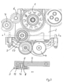
- a gear drive gear and a mass shaft drive gear are non-rotatably attached to the extension of the crankshaft, as shown in Fig.1 is shown.
- the gear drive gear is in engagement with a stepped gear, which in turn meshes with a camshaft gear.
- the gear drive gear also drives an oil pump gear, which is part of an oil pump arranged in the gear drive housing.
- crankshaft gear 1 is attached to the crankshaft and is operatively connected to the mass balance shafts 4 by means of the intermediate gear screwed to the bearing cover 2.
- a centering seat 5 is arranged in the bearing cover 2.
- the crankshaft gear 1 attached to the crankshaft is operatively connected to the intermediate gear of the oil pump 6, which in turn is operatively connected to the drive gear of the oil pump 7.
- the screwed-on bearing bolt 8 receives the roller-bearing intermediate gear 3 screwed to the bearing cover 2 with the screw 16 and the roller bearing 15.
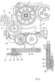
- FIG.2 A front view of the internal combustion engine with partially assembled gear drive with differential gear and plain bearing intermediate gear is shown.
- the mass balance gear is driven by a balance shaft intermediate gear, which in turn drives a drive gear arranged axially in front of a balance shaft gear which meshes with a second balance shaft gear.
- the crankshaft gear 1 is attached to the crankshaft and is operatively connected to the mass balance shafts 4 by means of the intermediate gear 3 screwed to the bearing cover 2. Furthermore, the crankshaft gear 1 attached to the crankshaft is operatively connected to the intermediate gear 3, which in turn is operatively connected to the drive gear of the oil pump 7.
- the cast-on bearing bolt 9 accommodates the plain-bearing intermediate gear 3, which is screwed to the bearing cover 2 with the thrust washer 10 and the screw 16.
- the annular gap for the oil supply 11 is supplied with oil for the oil supply 13 of the plain bearing 14 from the annular gap 11 by means of the oil inlet 12 from the bearing seat bore into the annular gap.
- FIG.3 shows a front view of the internal combustion engine with partially assembled gear drive with differential gear and roller bearing intermediate gear 3.
- the crankshaft gear 1 is attached to the crankshaft and is operatively connected to the mass balance shafts 4 by means of the intermediate gear screwed to the bearing cover 2.
- a centering seat 5 is arranged in the bearing cover on the bearing cover 2.
- the crankshaft gear 1 attached to the crankshaft is operatively connected to the intermediate gear of the oil pump 6, which in turn is operatively connected to the drive gear of the oil pump 7.
- the screwed-on bearing bolt 8 receives the roller bearing intermediate gear 3 screwed to the bearing cover 2 with the screw 16 and the roller bearing 15.
- Fig.4 shows a front view of the internal combustion engine with partially assembled gear drive with differential gear and plain bearing intermediate gear 3.
- the crankshaft gear 1 is attached to the crankshaft and is operatively connected to the mass balance shafts 4 by means of the intermediate gear 3 screwed to the bearing cover 2. Furthermore, the crankshaft gear 1 attached to the crankshaft is operatively connected to the intermediate gear 3, which in turn is operatively connected to the drive gear of the oil pump 7.
- the cast-on bearing bolt 9 accommodates the plain bearing intermediate gear 3, which is screwed to the bearing cover 2 with the thrust washer 10 and the screw 16.
- the annular gap for the oil supply 11 is supplied with oil for the oil supply 13 of the plain bearing 14 from the annular gap 11 by means of the oil inlet 12 from the bearing seat bore into the annular gap.
Landscapes
- Engineering & Computer Science (AREA)
- General Engineering & Computer Science (AREA)
- Mechanical Engineering (AREA)
- Physics & Mathematics (AREA)
- Acoustics & Sound (AREA)
- Aviation & Aerospace Engineering (AREA)
- Chemical & Material Sciences (AREA)
- Combustion & Propulsion (AREA)
- Lubrication Of Internal Combustion Engines (AREA)
- Gear Transmission (AREA)
- Shafts, Cranks, Connecting Bars, And Related Bearings (AREA)
Description
- Die Erfindung betrifft eine Brennkraftmaschine mit einem Kurbelgehäuse, in dem eine Kurbelwelle drehbar gelagert ist, an der zumindest ein einen Kolben tragendes Pleuel angelenkt ist, wobei der Kolben in einem von einem Zylinderkopf unter Bildung eines Brennraums abgedeckten Zylinder bewegbar ist und in dem Zylinderkopf Gaswechselventile angeordnet sind, die von mindestens einer Nockenwelle betätigt werden, die über ein Getriebe mit einem auf der Kurbelwelle angeordneten Rädertriebzahnrad verbunden ist, wobei ein Massenausgleichsgetriebe mit zwei Ausgleichswellen vorhanden ist.
- Derzeit werden Massenausgleichsgetriebe über auf den Kurbelwellenwangen aufgezogene Zahnräder angetrieben. Diese Zahnräder sind systembedingt sehr groß und schwierig zu montieren. Diese aufwendige und kostenintensive Antriebsvariante wird durch einen stark begrenzten Bauraum bestimmt. Schmierölpumpen werden teilweise über im Kurbelgehäuse angebaute Zwischenradlagerungen angetrieben. Dadurch ergeben sich höhere Toleranzketten und die Problematik einer ungünstigen Schmierölversorgung der Zwischenradlagerung. Teilweise müssen beide Systeme gleichzeitig verbaut werden, um die Ölpumpe und gleichzeitig ein Massenausgleichsgetriebe antreiben zu können.
- Aus der
DE 10 2012 001043 A1 ist eine Brennkraftmaschine mit einem Massenausgleichsgetriebe mit zwei Massenausgleichswellen bekannt. - Weiter ist eine derartige Brennkraftmaschine aus der
DE 41 28 432 A1 bekannt. Bei dieser Brennkraftmaschine ist ein Massenausgleichsgetriebe verbaut, das direkt in das Kurbelgehäuse der Brennkraftmaschine integriert ist. Einerseits ergibt sich dadurch die Möglichkeit, die Lagerstellen für die Ausgleichswellen des Massenausgleichsgetriebes bei der Bearbeitung des Kurbelgehäuses in einem gemeinsamen Arbeitsgang bei der Bearbeitung beziehungsweise Fertigung der Lagerstellen für beispielsweise die Kurbelwelle, Zwischenräder und die Nockenwelle zu fertigen. Dadurch ist eine sehr genaue Einhaltung der Abstände der einzelnen Lagerstellen zueinander möglich. Andererseits ist insbesondere bei Brennkraftmaschinen, die als Industriemotoren, Nutzfahrzeugmotoren oder Baumaschinenmotoren eingesetzt werden, ein Massenausgleichsgetriebe nur bedarfsweise erforderlich. Für den Fall, dass kein Massenausgleichsgetriebe benötigt wird, stellt zumindest die Bearbeitung der Lagerstellen für das Massenausgleichsgetriebe in dem Kurbelgehäuse einen zusätzliche Kosten verursachenden Mehraufwand dar. - Aus der
DE 102 40 713 A1 ist eine Vorrichtung bekannt zum Ausgleich der Massenkräfte für eine Brennkraftmaschine mit zwei mit doppelter Kurbelwellendrehzahl gegenläufig betriebenen Ausgleichswellen, die unterhalb der Kurbelwelle, innerhalb der unter dem Kurbelgehäuse angebrachten Ölwanne angeordnet sind. - Daran ist nachteilig, dass die beschriebenen Varianten voluminös und teuer sind.
- Der Erfindung liegt die Aufgabe zugrunde, eine Brennkraftmaschine bereitzustellen, die eine bauraumoptimierte und kostengünstige Antriebsvariante für den Antrieb einer Schmierölpumpe oder eines Massenausgleichsgetriebes oder beides in einer Brennkraftmaschine darstellt.
- Diese Aufgabe wird dadurch gelöst, dass das Massenausgleichsgetriebe in einem Getrieberahmen angeordnet unterhalb der Kurbelwelle an das Kurbelgehäuse angebaut ist und von einem auf der Kurbelwelle angeordneten Antriebzahnrad angetrieben ist. Durch diese Ausbildung sind zunächst einmal, abgesehen von mit geringem Aufwand zu fertigenden Befestigungsgewinden für den Getrieberahmen, an dem Kurbelgehäuse keine unnötigen Bearbeitungsvorgänge erforderlich.
- Hier wird vorteilhafterweise eine Zwischenradlagerung zum Antrieb einer Schmierölpumpe und/oder eines Massenausgleichgetriebes in den Hauptlagerstuhl integriert, so wird bei nur begrenzt vorhandenem Bauraum der Antrieb einer Ölpumpe und/oder eines Massenausgleichgetriebes möglich. Zur Schmierung des Zwischenrads wird die notwendige Ölmenge durch den Hauptlagerstuhl bereitgestellt. In einer alternativen Weiterbildung ist vorgesehen, dass das Zwischenrad mit einer Wälzlagerung ausgestattet ist, damit keine aktive Schmierstoffzufuhr aus dem Lagerstuhl notwendig ist. Ein weiterer Vorteil ist, dass sowohl Winkelfehler der Zahnräder als auch das Zahnflankenspiel zu dem auf der Kurbelwelle befindlichen Antriebszahnrad minimiert werden. Eine weitere andere vorteilhafte Weiterbildung sieht vor, dass die Schmierölversorgung der Zwischenradlagerung aus der Schmierölversorgung des Hauptlagers auf der Kurbelgehäuseseite abgegriffen wird. Eine Variante sieht vor, dass die Versorgungsbohrung des kurbelgehäuseseitigen Lagerstuhles angebohrt wird und die in die im Hauptlagerdeckel integrierte Zwischenradlagerung weitergeleitet wird. Eine andere Variante sieht vor, dass die Ölversorgung der Zwischenradlagerung durch eine kurbelgehäuseseitig verbaute Lagerschale mit integrierter rückenseitiger Ölversorgungsnut realisiert wird. Eine weitere Variante sieht vor, dass zur Ölversorgung der Zwischenradlagerung eine der Hauptlagerschraubenpfeifen mit Drucköl versorgt wird, wobei das Öl in den Lagerungszapfen zur Zwischenradschmierung eingespeist wird.
- In Weiterbildung der Erfindung sind zwei miteinander kämmende Ausgleichswellenzahnräder vorgesehen und es ist axial neben einem Ausgleichswellenzahnrad ein Antriebszahnrad angeordnet, das über ein Ausgleichswellenzwischenzahnrad mit dem Massentriebzahnrad in Eingriff steht. Durch diese Kombination ist einerseits das einzustellende Übersetzungsverhältnis realisierbar, andererseits wird durch das Ausgleichswellenzwischenrad der Achsabstand zwischen der Kurbelwelle und den beiden Ausgleichswellen überbrückt.
- In weiterer Ausgestaltung der Erfindung steht ein Ölpumpenzahnrad direkt mit dem Rädertriebzahnrad in Eingriff.
- Weitere vorteilhafte Ausgestaltungen der Erfindung sind der Zeichnungsbeschreibung zu entnehmen, in der ein in den Figuren dargestelltes Ausführungsbeispiel näher beschrieben ist. Es zeigen:
- Fig. 1
- eine Vorderansicht der Brennkraftmaschine mit teilmontiertem Rädertrieb mit Ausgleichsgetriebe und wälzgelagertem Zwischenrad
- Fig. 2
- eine Vorderansicht der Brennkraftmaschine mit teilmontiertem Rädertrieb mit Ausgleichsgetriebe und gleitgelagertem Zwischenrad
- Fig. 3
- eine Vorderansicht der Brennkraftmaschine mit teilmontiertem Rädertrieb mit Ausgleichsgetriebe und wälzgelagertem Zwischenrad
- Fig. 4
- eine Vorderansicht der Brennkraftmaschine mit teilmontiertem Rädertrieb mit Ausgleichsgetriebe und gleitgelagertem Zwischenrad.
- Auf den Fortsatz der Kurbelwelle ist ein Rädertriebzahnrad und ein Massenwellentriebzahnrad drehfest befestigt, wie in
Fig. 1 gezeigt wird. Das Rädertriebzahnrad steht im Eingriff mit einem Stufenzahnrad, das wiederum mit einem Nockenwellenzahnrad kämmt. Ebenfalls von dem Rädertriebzahnrad wird ein Ölpumpenzahnrad angetrieben, das Bestandteil einer in dem Rädertriebgehäuse angeordneten Ölpumpe ist. - Das Kurbelwellenzahnrad 1 ist an der Kurbelwelle befestigt und steht mittels des am Lagerdeckel 2 angeschraubten Zwischenrads mit den Massenausgleichswellen 4 in Wirkverbindung. Am Lagerdeckel 2 ist eine Zentrieraufnahme 5 im Lagerdeckel angeordnet. Weiter ist das an der Kurbelwelle befestigte Kurbelwellenzahnrad 1 in einer Wirkverbindung mit dem Zwischenrad der Ölpumpe 6, welches wiederrum in einer Wirkverbindung mit dem Antriebsrad der Ölpumpe 7 steht. Der angeschraubte Lagerbolzen 8 nimmt das wälzgelagerte Zwischenrad 3 mit der Schraube 16 und dem Wälzlager 15 am Lagerdeckel 2 angeschraubt auf.
- In der Ansicht nach
Fig. 2 wird eine Vorderansicht der Brennkraftmaschine mit teilmontiertem Rädertrieb mit Ausgleichsgetriebe und gleitgelagertem Zwischenrad dargestellt. - Das Massenausgleichsgetriebe wird über ein Ausgleichswellenzwischenrad angetrieben, das seinerseits ein Antriebszahnrad antreibt, das axial vor einem Ausgleichswellenzahnrad angeordnet ist, das mit einem zweiten Ausgleichswellenzahnrad in Eingriff steht.
- Diese beiden Ausgleichswellenzahnräder sind mit den Massenausgleichswellen verbunden, die in dem Getrieberahmen 17 des Massenausgleichsgetriebes gelagert sind. Dieser Getrieberahmen wird direkt an der Unterseite des Kurbelgehäuses festgeschraubt. Das Kurbelwellenzahnrad 1 ist an der Kurbelwelle befestigt und steht mittels des am Lagerdeckel 2 angeschraubten Zwischenrads 3 mit den Massenausgleichswellen 4 in Wirkverbindung. Weiter ist das an der Kurbelwelle befestigte Kurbelwellenzahnrad 1 in einer Wirkverbindung mit dem Zwischenrad 3, welches wiederum in einer Wirkverbindung mit dem Antriebsrad der Ölpumpe 7 steht. Der angegossene Lagerbolzen 9 nimmt das gleitgelagerte Zwischenrad 3 auf, welches mit der Anlaufscheibe 10 und der Schraube 16 am Lagerdeckel 2 angeschraubt ist. Der Ringspalt für die Ölversorgung 11 wird mittels des Ölzulaufs 12 aus der Lagerstuhlbohrung in den Ringspalt mit Öl zur Ölversorgung 13 des Gleitlagers 14 aus dem Ringspalt 11 versorgt.
- Die Darstellung in
Fig. 3 zeigt eine Vorderansicht der Brennkraftmaschine mit teilmontiertem Rädertrieb mit Ausgleichsgetriebe und wälzgelagertem Zwischenrad 3. Das Kurbelwellenzahnrad 1 ist an der Kurbelwelle befestigt und steht mittels des am Lagerdeckel 2 angeschraubten Zwischenrads mit den Massenausgleichswellen 4 in Wirkverbindung. Am Lagerdeckel 2 ist eine Zentrieraufnahme 5 im Lagerdeckel angeordnet. Weiter ist das an der Kurbelwelle befestigte Kurbelwellenzahnrad 1 in einer Wirkverbindung mit dem Zwischenrad der Ölpumpe 6, welches wiederum in einer Wirkverbindung mit dem Antriebsrad der Ölpumpe 7 steht. Der angeschraubte Lagerbolzen 8 nimmt das wälzgelagerte Zwischenrad 3 mit der Schraube 16 und dem Wälzlager 15 am Lagerdeckel 2 angeschraubt auf. -
Fig. 4 zeigt eine Vorderansicht der Brennkraftmaschine mit teilmontiertem Rädertrieb mit Ausgleichsgetriebe und gleitgelagertem Zwischenrad 3. Das Kurbelwellenzahnrad 1 ist an der Kurbelwelle befestigt und steht mittels des am Lagerdeckel 2 angeschraubten Zwischenrads 3 mit den Massenausgleichswellen 4 in Wirkverbindung. Weiter ist das an der Kurbelwelle befestigte Kurbelwellenzahnrad 1 in einer Wirkverbindung mit dem Zwischenrad 3, welches wiederum in einer Wirkverbindung mit dem Antriebsrad der Ölpumpe 7 steht. Der angegossene Lagerbolzen 9 nimmt das gleitgelagerte Zwischenrad 3 auf, welches mit der Anlaufscheibe 10 und der Schraube 16 am Lagerdeckel 2 angeschraubt ist. Der Ringspalt für die Ölversorgung 11 wird mittels des Ölzulaufs 12 aus der Lagerstuhlbohrung in den Ringspalt mit Öl zur Ölversorgung 13 des Gleitlagers 14 aus dem Ringspalt 11 versorgt. -
- 1
- Kurbelwellenzahnrad
- 2
- Lagerdeckel
- 3
- Zwischenrad am Lagerdeckel angeschraubt
- 4
- Massenausgleichswellen
- 5
- Zentrieraufnahme im Lagerdeckel
- 6
- Zwischenrad Ölpumpe
- 7
- Antriebsrad der Ölpumpe
- 8
- Lagerbolzen angeschraubt
- 9
- Lagerbolzen am Lagerdeckel angegossen
- 10
- Anlaufscheibe
- 11
- Ringspalt für Ölversorgung
- 12
- Ölzulauf aus Lagerstuhlbohrung in den Ringspalt
- 13
- Ölversorgung des Gleitlagers aus dem Ringspalt
- 14
- Gleitlager des Zwischenrads
- 15
- Wälzlager des Zwischenrads
- 16
- Schraube
- 17
- Getrieberahmen
Claims (4)
- Brennkraftmaschine mit einem Kurbelgehäuse, in dem eine Kurbelwelle in Lagern mit Lagerdeckeln (2) drehbar gelagert ist, an der zumindest ein einen Kolben tragendes Pleuel angelenkt ist, wobei der Kolben in einem von einem Zylinderkopf unter Bildung eines Brennraums abgedeckten Zylinder bewegbar ist und in dem Zylinderkopf Gaswechselventile angeordnet sind, die von mindestens einer Nockenwelle betätigt werden, die über ein Getriebe mit einem auf der Kurbelwelle angeordneten Kurbelwellenzahnrad (1) verbunden ist, wobei ein Massenausgleichsgetriebe mit zwei Ausgleichswellen (4) vorhanden ist,
dadurch gekennzeichnet, dass das Massenausgleichsgetriebe in einem Getrieberahmen (17) angeordnet unterhalb der Kurbelwelle an das Kurbelgehäuse angebaut ist und von dem auf der Kurbelwelle angeordneten Kurbelwellenzahnrad (1) durch ein neben dem Kurbelwellenzahnrad (1) angeordneten Zwischenrad (3) angetrieben ist, und wobei das Zwischenrad (3) am Hauptlagerdeckel (2) angeordnet ist. - Brennkraftmaschine nach Anspruch 1 ,
dadurch gekennzeichnet, dass die Schmierölversorgung einer Zwischenradlagerung aus einer Schmierölversorgung eines Hauptlagers kurbelgehäuseseitig dergestalt abgegriffen wird, dass eine Versorgungsbohrung eines kurbelgehäuseseitigen Lagerstuhles angebohrt wird und in die im Hauptlagerdeckel integrierte Zwischenradlagerung weitergeleitet. - Brennkraftmaschine nach Anspruch 1 ,
dadurch gekennzeichnet, dass die Schmierölversorgung einer Zwischenradlagerung aus einer Schmierölversorgung eines Hauptlagers kurbelgehäuseseitig dergestalt abgegriffen wird, dass eine Ölversorgung der Zwischenradlagerung durch eine kurbelgehäuseseitig verbaute Lagerschale mit einer integrierten rückenseitigen Ölversorgungsnut erfolgt. - Verfahren zum Betreiben einer Brennkraftmaschine,
dadurch gekennzeichnet, dass eine Vorrichtung nach einem oder mehreren der vorgenannten Ansprüche zum Einsatz kommt.
Applications Claiming Priority (2)
| Application Number | Priority Date | Filing Date | Title |
|---|---|---|---|
| DE102019003288.8A DE102019003288A1 (de) | 2019-05-09 | 2019-05-09 | Brennkraftmaschine mit Massenausgleichsgetriebe mit zwei Ausgleichswellen |
| PCT/EP2020/000083 WO2020224796A1 (de) | 2019-05-09 | 2020-04-14 | Brennkraftmaschine mit massenausgleichsgetriebe mit zwei ausgleichswellen |
Publications (2)
| Publication Number | Publication Date |
|---|---|
| EP3966470A1 EP3966470A1 (de) | 2022-03-16 |
| EP3966470B1 true EP3966470B1 (de) | 2024-07-17 |
Family
ID=70391061
Family Applications (1)
| Application Number | Title | Priority Date | Filing Date |
|---|---|---|---|
| EP20720737.4A Active EP3966470B1 (de) | 2019-05-09 | 2020-04-14 | Brennkraftmaschine mit massenausgleichsgetriebe mit zwei ausgleichswellen |
Country Status (6)
| Country | Link |
|---|---|
| US (1) | US11971080B2 (de) |
| EP (1) | EP3966470B1 (de) |
| JP (1) | JP7432191B2 (de) |
| CN (1) | CN113785138B (de) |
| DE (1) | DE102019003288A1 (de) |
| WO (1) | WO2020224796A1 (de) |
Citations (1)
| Publication number | Priority date | Publication date | Assignee | Title |
|---|---|---|---|---|
| EP0916833B1 (de) * | 1997-11-13 | 2002-12-04 | Bayerische Motoren Werke Aktiengesellschaft, Patentabteilung AJ-3 | Antriebsanordnung für eine Ausgleichsvorrichtung II. Ordnung für eine Hubkolben-Brennkraftmaschine |
Family Cites Families (19)
| Publication number | Priority date | Publication date | Assignee | Title |
|---|---|---|---|---|
| US3094190A (en) * | 1960-06-08 | 1963-06-18 | Gen Motors Corp | Internal combustion engine |
| US3710774A (en) | 1970-10-26 | 1973-01-16 | Allis Chalmers Mfg Co | Lube oil pump drive for balancer |
| JPS5637155Y2 (de) | 1978-03-29 | 1981-09-01 | ||
| JPS5820750U (ja) | 1981-08-03 | 1983-02-08 | 石川島芝浦機械株式会社 | 内燃機関の二次バランサ装置 |
| US5107802A (en) * | 1990-05-28 | 1992-04-28 | Honda Giken Kogyo Kabushiki Kaisha | Valve driving mechanism for internal combustion engines |
| DE4128432C2 (de) | 1991-08-27 | 2000-04-27 | Deutz Ag | Rädertrieb |
| JPH0616748U (ja) | 1992-08-07 | 1994-03-04 | 株式会社クボタ | 多気筒エンジンのバランサケース組付装置 |
| DE19936103C2 (de) | 1999-07-31 | 2001-12-20 | Daimler Chrysler Ag | Brennkraftmaschine |
| JP2001280422A (ja) | 2000-03-31 | 2001-10-10 | Aisin Seiki Co Ltd | エンジンバランサの取付構造 |
| GB0118478D0 (en) | 2001-07-28 | 2001-09-19 | Cummins Engine Co Ltd | Balancer shaft assembly |
| JP3845321B2 (ja) | 2002-03-11 | 2006-11-15 | 本田技研工業株式会社 | エンジンのバランサー装置 |
| DE10240713B4 (de) | 2002-09-04 | 2013-06-06 | Deutz Ag | Massenausgleichsvorrichtung |
| KR100482125B1 (ko) * | 2002-10-17 | 2005-04-14 | 현대자동차주식회사 | 엔진의 밸런서 설치구조 |
| JP2007239521A (ja) | 2006-03-07 | 2007-09-20 | Hitachi Ltd | 内燃機関のバランサ装置及び該バランサ装置の組付方法 |
| KR101055084B1 (ko) * | 2008-12-03 | 2011-08-08 | 현대자동차주식회사 | 차량용 밸런스샤프트 모듈 |
| JP2011144701A (ja) | 2010-01-12 | 2011-07-28 | Honda Motor Co Ltd | 内燃機関の潤滑油供給装置 |
| JP2011163252A (ja) * | 2010-02-12 | 2011-08-25 | Honda Motor Co Ltd | エンジン |
| DE102011075897A1 (de) | 2011-05-16 | 2012-11-22 | Schaeffler Technologies AG & Co. KG | Massenausgleichsgetriebe einer Brennkraftmaschine |
| DE102012001043A1 (de) * | 2012-01-20 | 2012-08-16 | Daimler Ag | Verfahren zum Herstellen einer Hubkolben-Verbrennungskraftmaschine sowie Hubkolben-Verbrennungskraftmaschine |
-
2019
- 2019-05-09 DE DE102019003288.8A patent/DE102019003288A1/de not_active Withdrawn
-
2020
- 2020-04-14 US US17/607,992 patent/US11971080B2/en active Active
- 2020-04-14 EP EP20720737.4A patent/EP3966470B1/de active Active
- 2020-04-14 CN CN202080033759.3A patent/CN113785138B/zh active Active
- 2020-04-14 WO PCT/EP2020/000083 patent/WO2020224796A1/de not_active Ceased
- 2020-04-14 JP JP2021560751A patent/JP7432191B2/ja active Active
Patent Citations (1)
| Publication number | Priority date | Publication date | Assignee | Title |
|---|---|---|---|---|
| EP0916833B1 (de) * | 1997-11-13 | 2002-12-04 | Bayerische Motoren Werke Aktiengesellschaft, Patentabteilung AJ-3 | Antriebsanordnung für eine Ausgleichsvorrichtung II. Ordnung für eine Hubkolben-Brennkraftmaschine |
Also Published As
| Publication number | Publication date |
|---|---|
| CN113785138A (zh) | 2021-12-10 |
| US11971080B2 (en) | 2024-04-30 |
| WO2020224796A1 (de) | 2020-11-12 |
| CN113785138B (zh) | 2024-04-26 |
| JP2022531086A (ja) | 2022-07-06 |
| EP3966470A1 (de) | 2022-03-16 |
| JP7432191B2 (ja) | 2024-02-16 |
| US20220325776A1 (en) | 2022-10-13 |
| DE102019003288A1 (de) | 2020-11-12 |
Similar Documents
| Publication | Publication Date | Title |
|---|---|---|
| DE3541065C2 (de) | ||
| EP0979929B1 (de) | Hubkolbenmotor mit Kipphebel-Ventilsteuerung | |
| EP1802850B1 (de) | Lebensdauergeschmierter nockenwellentrieb für eine brennkraftmaschine | |
| DE69204798T2 (de) | Brennkraftmaschine mit Schmierpumpen auf der Nockenwelle. | |
| EP3483478B1 (de) | Rädertrieb | |
| DE10249175A1 (de) | Fahrzeugantriebseinheit | |
| EP3966470B1 (de) | Brennkraftmaschine mit massenausgleichsgetriebe mit zwei ausgleichswellen | |
| DE4304743C2 (de) | Antriebsaggregat für ein Kraftfahrzeug | |
| DE102016203074B3 (de) | Getriebemotor | |
| DE3119362C2 (de) | Vierzylinder-Brennkraftmaschine mit einem Massenausgleich zweiter Ordnung | |
| DE102009043504A1 (de) | Hubkolbenmechanismus mit variablem Verdichtungsverhältnis | |
| DE102012005578A1 (de) | Verbrennungskraftmaschine, insbesondere für einen Kraftwagen | |
| DE102008021529B4 (de) | Plattenartige Trägerstruktur zur Aufnahme einer Ölpumpe | |
| DE112015005119B4 (de) | Mechanische Vorrichtung, umfassend eine Mehrzahl von Drehwellen | |
| WO2014037145A1 (de) | Brennkraftmaschine mit einem kurbelgehäuse | |
| DE102009050628B4 (de) | Vorrichtung zum Ausgleich der Massenkräfte zweiter Ordnung für eine Reihenhubkolbenbrennkraftmaschine | |
| EP1452769B1 (de) | Rädertrieb einer Brennkraftmaschine | |
| EP3891005B1 (de) | Verbrennungskraftmaschine mit kraftabnahme mit winkelausgleich und ölgeschmierter abtriebsverzahnung | |
| EP1700729A1 (de) | Antriebseinheit für ein Kraftfahrzeug | |
| DE19952097A1 (de) | Ölkreislauf in einer Brennkraftmaschine | |
| EP1860288A2 (de) | Modul zur Druckumlaufschmierung einer Brennkraftmaschine | |
| DE4335751C1 (de) | Zwischenzahnrad mit Gleitlagerung | |
| DE10009563A1 (de) | Brennkraftmaschine mit einer Ölwanne als integrierter Aggregateträger | |
| DE4446599C1 (de) | Kurbelwellen- Anordnung für eine ein- oder mehrzylindrige Brennkraftmaschine | |
| WO2008043810A1 (de) | Kurbelgehäuse für einen verbrennungsmotor mit einer ölwanne |
Legal Events
| Date | Code | Title | Description |
|---|---|---|---|
| STAA | Information on the status of an ep patent application or granted ep patent |
Free format text: STATUS: UNKNOWN |
|
| STAA | Information on the status of an ep patent application or granted ep patent |
Free format text: STATUS: THE INTERNATIONAL PUBLICATION HAS BEEN MADE |
|
| PUAI | Public reference made under article 153(3) epc to a published international application that has entered the european phase |
Free format text: ORIGINAL CODE: 0009012 |
|
| STAA | Information on the status of an ep patent application or granted ep patent |
Free format text: STATUS: REQUEST FOR EXAMINATION WAS MADE |
|
| 17P | Request for examination filed |
Effective date: 20211108 |
|
| AK | Designated contracting states |
Kind code of ref document: A1 Designated state(s): AL AT BE BG CH CY CZ DE DK EE ES FI FR GB GR HR HU IE IS IT LI LT LU LV MC MK MT NL NO PL PT RO RS SE SI SK SM TR |
|
| DAV | Request for validation of the european patent (deleted) | ||
| DAX | Request for extension of the european patent (deleted) | ||
| STAA | Information on the status of an ep patent application or granted ep patent |
Free format text: STATUS: EXAMINATION IS IN PROGRESS |
|
| 17Q | First examination report despatched |
Effective date: 20231109 |
|
| GRAP | Despatch of communication of intention to grant a patent |
Free format text: ORIGINAL CODE: EPIDOSNIGR1 |
|
| STAA | Information on the status of an ep patent application or granted ep patent |
Free format text: STATUS: GRANT OF PATENT IS INTENDED |
|
| INTG | Intention to grant announced |
Effective date: 20240319 |
|
| GRAS | Grant fee paid |
Free format text: ORIGINAL CODE: EPIDOSNIGR3 |
|
| GRAA | (expected) grant |
Free format text: ORIGINAL CODE: 0009210 |
|
| STAA | Information on the status of an ep patent application or granted ep patent |
Free format text: STATUS: THE PATENT HAS BEEN GRANTED |
|
| AK | Designated contracting states |
Kind code of ref document: B1 Designated state(s): AL AT BE BG CH CY CZ DE DK EE ES FI FR GB GR HR HU IE IS IT LI LT LU LV MC MK MT NL NO PL PT RO RS SE SI SK SM TR |
|
| REG | Reference to a national code |
Ref country code: CH Ref legal event code: EP |
|
| REG | Reference to a national code |
Ref country code: DE Ref legal event code: R096 Ref document number: 502020008598 Country of ref document: DE |
|
| REG | Reference to a national code |
Ref country code: IE Ref legal event code: FG4D Free format text: LANGUAGE OF EP DOCUMENT: GERMAN |
|
| P01 | Opt-out of the competence of the unified patent court (upc) registered |
Free format text: CASE NUMBER: APP_42549/2024 Effective date: 20240718 |
|
| REG | Reference to a national code |
Ref country code: LT Ref legal event code: MG9D |
|
| REG | Reference to a national code |
Ref country code: NL Ref legal event code: MP Effective date: 20240717 |
|
| PG25 | Lapsed in a contracting state [announced via postgrant information from national office to epo] |
Ref country code: PT Free format text: LAPSE BECAUSE OF FAILURE TO SUBMIT A TRANSLATION OF THE DESCRIPTION OR TO PAY THE FEE WITHIN THE PRESCRIBED TIME-LIMIT Effective date: 20241118 |
|
| PG25 | Lapsed in a contracting state [announced via postgrant information from national office to epo] |
Ref country code: NL Free format text: LAPSE BECAUSE OF FAILURE TO SUBMIT A TRANSLATION OF THE DESCRIPTION OR TO PAY THE FEE WITHIN THE PRESCRIBED TIME-LIMIT Effective date: 20240717 |
|
| PG25 | Lapsed in a contracting state [announced via postgrant information from national office to epo] |
Ref country code: PT Free format text: LAPSE BECAUSE OF FAILURE TO SUBMIT A TRANSLATION OF THE DESCRIPTION OR TO PAY THE FEE WITHIN THE PRESCRIBED TIME-LIMIT Effective date: 20241118 Ref country code: NL Free format text: LAPSE BECAUSE OF FAILURE TO SUBMIT A TRANSLATION OF THE DESCRIPTION OR TO PAY THE FEE WITHIN THE PRESCRIBED TIME-LIMIT Effective date: 20240717 |
|
| PG25 | Lapsed in a contracting state [announced via postgrant information from national office to epo] |
Ref country code: NO Free format text: LAPSE BECAUSE OF FAILURE TO SUBMIT A TRANSLATION OF THE DESCRIPTION OR TO PAY THE FEE WITHIN THE PRESCRIBED TIME-LIMIT Effective date: 20241017 |
|
| PG25 | Lapsed in a contracting state [announced via postgrant information from national office to epo] |
Ref country code: PL Free format text: LAPSE BECAUSE OF FAILURE TO SUBMIT A TRANSLATION OF THE DESCRIPTION OR TO PAY THE FEE WITHIN THE PRESCRIBED TIME-LIMIT Effective date: 20240717 Ref country code: FI Free format text: LAPSE BECAUSE OF FAILURE TO SUBMIT A TRANSLATION OF THE DESCRIPTION OR TO PAY THE FEE WITHIN THE PRESCRIBED TIME-LIMIT Effective date: 20240717 Ref country code: GR Free format text: LAPSE BECAUSE OF FAILURE TO SUBMIT A TRANSLATION OF THE DESCRIPTION OR TO PAY THE FEE WITHIN THE PRESCRIBED TIME-LIMIT Effective date: 20241018 |
|
| PG25 | Lapsed in a contracting state [announced via postgrant information from national office to epo] |
Ref country code: BG Free format text: LAPSE BECAUSE OF FAILURE TO SUBMIT A TRANSLATION OF THE DESCRIPTION OR TO PAY THE FEE WITHIN THE PRESCRIBED TIME-LIMIT Effective date: 20240717 |
|
| PG25 | Lapsed in a contracting state [announced via postgrant information from national office to epo] |
Ref country code: LV Free format text: LAPSE BECAUSE OF FAILURE TO SUBMIT A TRANSLATION OF THE DESCRIPTION OR TO PAY THE FEE WITHIN THE PRESCRIBED TIME-LIMIT Effective date: 20240717 |
|
| PG25 | Lapsed in a contracting state [announced via postgrant information from national office to epo] |
Ref country code: IS Free format text: LAPSE BECAUSE OF FAILURE TO SUBMIT A TRANSLATION OF THE DESCRIPTION OR TO PAY THE FEE WITHIN THE PRESCRIBED TIME-LIMIT Effective date: 20241117 |
|
| PG25 | Lapsed in a contracting state [announced via postgrant information from national office to epo] |
Ref country code: HR Free format text: LAPSE BECAUSE OF FAILURE TO SUBMIT A TRANSLATION OF THE DESCRIPTION OR TO PAY THE FEE WITHIN THE PRESCRIBED TIME-LIMIT Effective date: 20240717 |
|
| PG25 | Lapsed in a contracting state [announced via postgrant information from national office to epo] |
Ref country code: ES Free format text: LAPSE BECAUSE OF FAILURE TO SUBMIT A TRANSLATION OF THE DESCRIPTION OR TO PAY THE FEE WITHIN THE PRESCRIBED TIME-LIMIT Effective date: 20240717 Ref country code: RS Free format text: LAPSE BECAUSE OF FAILURE TO SUBMIT A TRANSLATION OF THE DESCRIPTION OR TO PAY THE FEE WITHIN THE PRESCRIBED TIME-LIMIT Effective date: 20241017 |
|
| PG25 | Lapsed in a contracting state [announced via postgrant information from national office to epo] |
Ref country code: RS Free format text: LAPSE BECAUSE OF FAILURE TO SUBMIT A TRANSLATION OF THE DESCRIPTION OR TO PAY THE FEE WITHIN THE PRESCRIBED TIME-LIMIT Effective date: 20241017 Ref country code: PL Free format text: LAPSE BECAUSE OF FAILURE TO SUBMIT A TRANSLATION OF THE DESCRIPTION OR TO PAY THE FEE WITHIN THE PRESCRIBED TIME-LIMIT Effective date: 20240717 Ref country code: NO Free format text: LAPSE BECAUSE OF FAILURE TO SUBMIT A TRANSLATION OF THE DESCRIPTION OR TO PAY THE FEE WITHIN THE PRESCRIBED TIME-LIMIT Effective date: 20241017 Ref country code: LV Free format text: LAPSE BECAUSE OF FAILURE TO SUBMIT A TRANSLATION OF THE DESCRIPTION OR TO PAY THE FEE WITHIN THE PRESCRIBED TIME-LIMIT Effective date: 20240717 Ref country code: IS Free format text: LAPSE BECAUSE OF FAILURE TO SUBMIT A TRANSLATION OF THE DESCRIPTION OR TO PAY THE FEE WITHIN THE PRESCRIBED TIME-LIMIT Effective date: 20241117 Ref country code: HR Free format text: LAPSE BECAUSE OF FAILURE TO SUBMIT A TRANSLATION OF THE DESCRIPTION OR TO PAY THE FEE WITHIN THE PRESCRIBED TIME-LIMIT Effective date: 20240717 Ref country code: GR Free format text: LAPSE BECAUSE OF FAILURE TO SUBMIT A TRANSLATION OF THE DESCRIPTION OR TO PAY THE FEE WITHIN THE PRESCRIBED TIME-LIMIT Effective date: 20241018 Ref country code: FI Free format text: LAPSE BECAUSE OF FAILURE TO SUBMIT A TRANSLATION OF THE DESCRIPTION OR TO PAY THE FEE WITHIN THE PRESCRIBED TIME-LIMIT Effective date: 20240717 Ref country code: ES Free format text: LAPSE BECAUSE OF FAILURE TO SUBMIT A TRANSLATION OF THE DESCRIPTION OR TO PAY THE FEE WITHIN THE PRESCRIBED TIME-LIMIT Effective date: 20240717 Ref country code: BG Free format text: LAPSE BECAUSE OF FAILURE TO SUBMIT A TRANSLATION OF THE DESCRIPTION OR TO PAY THE FEE WITHIN THE PRESCRIBED TIME-LIMIT Effective date: 20240717 |
|
| PG25 | Lapsed in a contracting state [announced via postgrant information from national office to epo] |
Ref country code: DK Free format text: LAPSE BECAUSE OF FAILURE TO SUBMIT A TRANSLATION OF THE DESCRIPTION OR TO PAY THE FEE WITHIN THE PRESCRIBED TIME-LIMIT Effective date: 20240717 Ref country code: SM Free format text: LAPSE BECAUSE OF FAILURE TO SUBMIT A TRANSLATION OF THE DESCRIPTION OR TO PAY THE FEE WITHIN THE PRESCRIBED TIME-LIMIT Effective date: 20240717 Ref country code: RO Free format text: LAPSE BECAUSE OF FAILURE TO SUBMIT A TRANSLATION OF THE DESCRIPTION OR TO PAY THE FEE WITHIN THE PRESCRIBED TIME-LIMIT Effective date: 20240717 |
|
| REG | Reference to a national code |
Ref country code: DE Ref legal event code: R097 Ref document number: 502020008598 Country of ref document: DE |
|
| PG25 | Lapsed in a contracting state [announced via postgrant information from national office to epo] |
Ref country code: EE Free format text: LAPSE BECAUSE OF FAILURE TO SUBMIT A TRANSLATION OF THE DESCRIPTION OR TO PAY THE FEE WITHIN THE PRESCRIBED TIME-LIMIT Effective date: 20240717 |
|
| PG25 | Lapsed in a contracting state [announced via postgrant information from national office to epo] |
Ref country code: CZ Free format text: LAPSE BECAUSE OF FAILURE TO SUBMIT A TRANSLATION OF THE DESCRIPTION OR TO PAY THE FEE WITHIN THE PRESCRIBED TIME-LIMIT Effective date: 20240717 |
|
| PG25 | Lapsed in a contracting state [announced via postgrant information from national office to epo] |
Ref country code: SK Free format text: LAPSE BECAUSE OF FAILURE TO SUBMIT A TRANSLATION OF THE DESCRIPTION OR TO PAY THE FEE WITHIN THE PRESCRIBED TIME-LIMIT Effective date: 20240717 |
|
| PLBE | No opposition filed within time limit |
Free format text: ORIGINAL CODE: 0009261 |
|
| STAA | Information on the status of an ep patent application or granted ep patent |
Free format text: STATUS: NO OPPOSITION FILED WITHIN TIME LIMIT |
|
| 26N | No opposition filed |
Effective date: 20250422 |
|
| PGFP | Annual fee paid to national office [announced via postgrant information from national office to epo] |
Ref country code: DE Payment date: 20250528 Year of fee payment: 6 |
|
| PG25 | Lapsed in a contracting state [announced via postgrant information from national office to epo] |
Ref country code: SE Free format text: LAPSE BECAUSE OF FAILURE TO SUBMIT A TRANSLATION OF THE DESCRIPTION OR TO PAY THE FEE WITHIN THE PRESCRIBED TIME-LIMIT Effective date: 20240717 |
|
| REG | Reference to a national code |
Ref country code: CH Ref legal event code: H13 Free format text: ST27 STATUS EVENT CODE: U-0-0-H10-H13 (AS PROVIDED BY THE NATIONAL OFFICE) Effective date: 20251125 |
|
| PG25 | Lapsed in a contracting state [announced via postgrant information from national office to epo] |
Ref country code: LU Free format text: LAPSE BECAUSE OF NON-PAYMENT OF DUE FEES Effective date: 20250414 |
|
| PG25 | Lapsed in a contracting state [announced via postgrant information from national office to epo] |
Ref country code: MC Free format text: LAPSE BECAUSE OF FAILURE TO SUBMIT A TRANSLATION OF THE DESCRIPTION OR TO PAY THE FEE WITHIN THE PRESCRIBED TIME-LIMIT Effective date: 20240717 |
|
| GBPC | Gb: european patent ceased through non-payment of renewal fee |
Effective date: 20250414 |
|
| REG | Reference to a national code |
Ref country code: BE Ref legal event code: MM Effective date: 20250430 |
|
| PG25 | Lapsed in a contracting state [announced via postgrant information from national office to epo] |
Ref country code: GB Free format text: LAPSE BECAUSE OF NON-PAYMENT OF DUE FEES Effective date: 20250414 |
|
| PG25 | Lapsed in a contracting state [announced via postgrant information from national office to epo] |
Ref country code: FR Free format text: LAPSE BECAUSE OF NON-PAYMENT OF DUE FEES Effective date: 20250430 |
|
| PG25 | Lapsed in a contracting state [announced via postgrant information from national office to epo] |
Ref country code: BE Free format text: LAPSE BECAUSE OF NON-PAYMENT OF DUE FEES Effective date: 20250430 |
|
| PG25 | Lapsed in a contracting state [announced via postgrant information from national office to epo] |
Ref country code: CH Free format text: LAPSE BECAUSE OF NON-PAYMENT OF DUE FEES Effective date: 20250430 |
|
| PG25 | Lapsed in a contracting state [announced via postgrant information from national office to epo] |
Ref country code: IT Free format text: LAPSE BECAUSE OF FAILURE TO SUBMIT A TRANSLATION OF THE DESCRIPTION OR TO PAY THE FEE WITHIN THE PRESCRIBED TIME-LIMIT Effective date: 20240717 |
|
| PG25 | Lapsed in a contracting state [announced via postgrant information from national office to epo] |
Ref country code: IE Free format text: LAPSE BECAUSE OF NON-PAYMENT OF DUE FEES Effective date: 20250414 |