EP3964724A1 - Rolle für rollenlager, anordnung mit einem schleifwerkzeug und einer rolle für ein rollenlager sowie verfahren zum herstellen einer rolle für ein rollenlager - Google Patents
Rolle für rollenlager, anordnung mit einem schleifwerkzeug und einer rolle für ein rollenlager sowie verfahren zum herstellen einer rolle für ein rollenlager Download PDFInfo
- Publication number
- EP3964724A1 EP3964724A1 EP21193248.8A EP21193248A EP3964724A1 EP 3964724 A1 EP3964724 A1 EP 3964724A1 EP 21193248 A EP21193248 A EP 21193248A EP 3964724 A1 EP3964724 A1 EP 3964724A1
- Authority
- EP
- European Patent Office
- Prior art keywords
- roller
- profile
- grinding tool
- grinding
- ground
- Prior art date
- Legal status (The legal status is an assumption and is not a legal conclusion. Google has not performed a legal analysis and makes no representation as to the accuracy of the status listed.)
- Granted
Links
Images


Classifications
-
- F—MECHANICAL ENGINEERING; LIGHTING; HEATING; WEAPONS; BLASTING
- F16—ENGINEERING ELEMENTS AND UNITS; GENERAL MEASURES FOR PRODUCING AND MAINTAINING EFFECTIVE FUNCTIONING OF MACHINES OR INSTALLATIONS; THERMAL INSULATION IN GENERAL
- F16C—SHAFTS; FLEXIBLE SHAFTS; ELEMENTS OR CRANKSHAFT MECHANISMS; ROTARY BODIES OTHER THAN GEARING ELEMENTS; BEARINGS
- F16C33/00—Parts of bearings; Special methods for making bearings or parts thereof
- F16C33/30—Parts of ball or roller bearings
- F16C33/34—Rollers; Needles
- F16C33/36—Rollers; Needles with bearing-surfaces other than cylindrical, e.g. tapered; with grooves in the bearing surfaces
- F16C33/366—Tapered rollers, i.e. rollers generally shaped as truncated cones
-
- B—PERFORMING OPERATIONS; TRANSPORTING
- B24—GRINDING; POLISHING
- B24B—MACHINES, DEVICES, OR PROCESSES FOR GRINDING OR POLISHING; DRESSING OR CONDITIONING OF ABRADING SURFACES; FEEDING OF GRINDING, POLISHING, OR LAPPING AGENTS
- B24B19/00—Single-purpose machines or devices for particular grinding operations not covered by any other main group
- B24B19/02—Single-purpose machines or devices for particular grinding operations not covered by any other main group for grinding grooves, e.g. on shafts, in casings, in tubes, homokinetic joint elements
- B24B19/06—Single-purpose machines or devices for particular grinding operations not covered by any other main group for grinding grooves, e.g. on shafts, in casings, in tubes, homokinetic joint elements for grinding races, e.g. roller races
-
- B—PERFORMING OPERATIONS; TRANSPORTING
- B24—GRINDING; POLISHING
- B24B—MACHINES, DEVICES, OR PROCESSES FOR GRINDING OR POLISHING; DRESSING OR CONDITIONING OF ABRADING SURFACES; FEEDING OF GRINDING, POLISHING, OR LAPPING AGENTS
- B24B41/00—Component parts such as frames, beds, carriages, headstocks
- B24B41/04—Headstocks; Working-spindles; Features relating thereto
-
- B—PERFORMING OPERATIONS; TRANSPORTING
- B24—GRINDING; POLISHING
- B24B—MACHINES, DEVICES, OR PROCESSES FOR GRINDING OR POLISHING; DRESSING OR CONDITIONING OF ABRADING SURFACES; FEEDING OF GRINDING, POLISHING, OR LAPPING AGENTS
- B24B5/00—Machines or devices designed for grinding surfaces of revolution on work, including those which also grind adjacent plane surfaces; Accessories therefor
- B24B5/36—Single-purpose machines or devices
- B24B5/37—Single-purpose machines or devices for grinding rolls, e.g. barrel-shaped rolls
-
- F—MECHANICAL ENGINEERING; LIGHTING; HEATING; WEAPONS; BLASTING
- F16—ENGINEERING ELEMENTS AND UNITS; GENERAL MEASURES FOR PRODUCING AND MAINTAINING EFFECTIVE FUNCTIONING OF MACHINES OR INSTALLATIONS; THERMAL INSULATION IN GENERAL
- F16C—SHAFTS; FLEXIBLE SHAFTS; ELEMENTS OR CRANKSHAFT MECHANISMS; ROTARY BODIES OTHER THAN GEARING ELEMENTS; BEARINGS
- F16C33/00—Parts of bearings; Special methods for making bearings or parts thereof
- F16C33/30—Parts of ball or roller bearings
- F16C33/34—Rollers; Needles
- F16C33/36—Rollers; Needles with bearing-surfaces other than cylindrical, e.g. tapered; with grooves in the bearing surfaces
-
- F—MECHANICAL ENGINEERING; LIGHTING; HEATING; WEAPONS; BLASTING
- F16—ENGINEERING ELEMENTS AND UNITS; GENERAL MEASURES FOR PRODUCING AND MAINTAINING EFFECTIVE FUNCTIONING OF MACHINES OR INSTALLATIONS; THERMAL INSULATION IN GENERAL
- F16C—SHAFTS; FLEXIBLE SHAFTS; ELEMENTS OR CRANKSHAFT MECHANISMS; ROTARY BODIES OTHER THAN GEARING ELEMENTS; BEARINGS
- F16C2202/00—Solid materials defined by their properties
- F16C2202/02—Mechanical properties
- F16C2202/08—Resilience, elasticity, super-elasticity
-
- F—MECHANICAL ENGINEERING; LIGHTING; HEATING; WEAPONS; BLASTING
- F16—ENGINEERING ELEMENTS AND UNITS; GENERAL MEASURES FOR PRODUCING AND MAINTAINING EFFECTIVE FUNCTIONING OF MACHINES OR INSTALLATIONS; THERMAL INSULATION IN GENERAL
- F16C—SHAFTS; FLEXIBLE SHAFTS; ELEMENTS OR CRANKSHAFT MECHANISMS; ROTARY BODIES OTHER THAN GEARING ELEMENTS; BEARINGS
- F16C2206/00—Materials with ceramics, cermets, hard carbon or similar non-metallic hard materials as main constituents
- F16C2206/40—Ceramics, e.g. carbides, nitrides, oxides, borides of a metal
- F16C2206/58—Ceramics, e.g. carbides, nitrides, oxides, borides of a metal based on ceramic nitrides
-
- F—MECHANICAL ENGINEERING; LIGHTING; HEATING; WEAPONS; BLASTING
- F16—ENGINEERING ELEMENTS AND UNITS; GENERAL MEASURES FOR PRODUCING AND MAINTAINING EFFECTIVE FUNCTIONING OF MACHINES OR INSTALLATIONS; THERMAL INSULATION IN GENERAL
- F16C—SHAFTS; FLEXIBLE SHAFTS; ELEMENTS OR CRANKSHAFT MECHANISMS; ROTARY BODIES OTHER THAN GEARING ELEMENTS; BEARINGS
- F16C2220/00—Shaping
- F16C2220/60—Shaping by removing material, e.g. machining
- F16C2220/62—Shaping by removing material, e.g. machining by turning, boring, drilling
-
- F—MECHANICAL ENGINEERING; LIGHTING; HEATING; WEAPONS; BLASTING
- F16—ENGINEERING ELEMENTS AND UNITS; GENERAL MEASURES FOR PRODUCING AND MAINTAINING EFFECTIVE FUNCTIONING OF MACHINES OR INSTALLATIONS; THERMAL INSULATION IN GENERAL
- F16C—SHAFTS; FLEXIBLE SHAFTS; ELEMENTS OR CRANKSHAFT MECHANISMS; ROTARY BODIES OTHER THAN GEARING ELEMENTS; BEARINGS
- F16C2220/00—Shaping
- F16C2220/60—Shaping by removing material, e.g. machining
- F16C2220/70—Shaping by removing material, e.g. machining by grinding
-
- F—MECHANICAL ENGINEERING; LIGHTING; HEATING; WEAPONS; BLASTING
- F16—ENGINEERING ELEMENTS AND UNITS; GENERAL MEASURES FOR PRODUCING AND MAINTAINING EFFECTIVE FUNCTIONING OF MACHINES OR INSTALLATIONS; THERMAL INSULATION IN GENERAL
- F16C—SHAFTS; FLEXIBLE SHAFTS; ELEMENTS OR CRANKSHAFT MECHANISMS; ROTARY BODIES OTHER THAN GEARING ELEMENTS; BEARINGS
- F16C2240/00—Specified values or numerical ranges of parameters; Relations between them
- F16C2240/30—Angles, e.g. inclinations
-
- F—MECHANICAL ENGINEERING; LIGHTING; HEATING; WEAPONS; BLASTING
- F16—ENGINEERING ELEMENTS AND UNITS; GENERAL MEASURES FOR PRODUCING AND MAINTAINING EFFECTIVE FUNCTIONING OF MACHINES OR INSTALLATIONS; THERMAL INSULATION IN GENERAL
- F16C—SHAFTS; FLEXIBLE SHAFTS; ELEMENTS OR CRANKSHAFT MECHANISMS; ROTARY BODIES OTHER THAN GEARING ELEMENTS; BEARINGS
- F16C2240/00—Specified values or numerical ranges of parameters; Relations between them
- F16C2240/40—Linear dimensions, e.g. length, radius, thickness, gap
- F16C2240/48—Particle sizes
-
- F—MECHANICAL ENGINEERING; LIGHTING; HEATING; WEAPONS; BLASTING
- F16—ENGINEERING ELEMENTS AND UNITS; GENERAL MEASURES FOR PRODUCING AND MAINTAINING EFFECTIVE FUNCTIONING OF MACHINES OR INSTALLATIONS; THERMAL INSULATION IN GENERAL
- F16C—SHAFTS; FLEXIBLE SHAFTS; ELEMENTS OR CRANKSHAFT MECHANISMS; ROTARY BODIES OTHER THAN GEARING ELEMENTS; BEARINGS
- F16C2300/00—Application independent of particular apparatuses
- F16C2300/10—Application independent of particular apparatuses related to size
- F16C2300/14—Large applications, e.g. bearings having an inner diameter exceeding 500 mm
-
- F—MECHANICAL ENGINEERING; LIGHTING; HEATING; WEAPONS; BLASTING
- F16—ENGINEERING ELEMENTS AND UNITS; GENERAL MEASURES FOR PRODUCING AND MAINTAINING EFFECTIVE FUNCTIONING OF MACHINES OR INSTALLATIONS; THERMAL INSULATION IN GENERAL
- F16C—SHAFTS; FLEXIBLE SHAFTS; ELEMENTS OR CRANKSHAFT MECHANISMS; ROTARY BODIES OTHER THAN GEARING ELEMENTS; BEARINGS
- F16C2322/00—Apparatus used in shaping articles
- F16C2322/12—Rolling apparatus, e.g. rolling stands, rolls
-
- F—MECHANICAL ENGINEERING; LIGHTING; HEATING; WEAPONS; BLASTING
- F16—ENGINEERING ELEMENTS AND UNITS; GENERAL MEASURES FOR PRODUCING AND MAINTAINING EFFECTIVE FUNCTIONING OF MACHINES OR INSTALLATIONS; THERMAL INSULATION IN GENERAL
- F16C—SHAFTS; FLEXIBLE SHAFTS; ELEMENTS OR CRANKSHAFT MECHANISMS; ROTARY BODIES OTHER THAN GEARING ELEMENTS; BEARINGS
- F16C2326/00—Articles relating to transporting
- F16C2326/01—Parts of vehicles in general
- F16C2326/02—Wheel hubs or castors
-
- F—MECHANICAL ENGINEERING; LIGHTING; HEATING; WEAPONS; BLASTING
- F16—ENGINEERING ELEMENTS AND UNITS; GENERAL MEASURES FOR PRODUCING AND MAINTAINING EFFECTIVE FUNCTIONING OF MACHINES OR INSTALLATIONS; THERMAL INSULATION IN GENERAL
- F16C—SHAFTS; FLEXIBLE SHAFTS; ELEMENTS OR CRANKSHAFT MECHANISMS; ROTARY BODIES OTHER THAN GEARING ELEMENTS; BEARINGS
- F16C2326/00—Articles relating to transporting
- F16C2326/10—Railway vehicles
-
- F—MECHANICAL ENGINEERING; LIGHTING; HEATING; WEAPONS; BLASTING
- F16—ENGINEERING ELEMENTS AND UNITS; GENERAL MEASURES FOR PRODUCING AND MAINTAINING EFFECTIVE FUNCTIONING OF MACHINES OR INSTALLATIONS; THERMAL INSULATION IN GENERAL
- F16C—SHAFTS; FLEXIBLE SHAFTS; ELEMENTS OR CRANKSHAFT MECHANISMS; ROTARY BODIES OTHER THAN GEARING ELEMENTS; BEARINGS
- F16C2360/00—Engines or pumps
- F16C2360/31—Wind motors
-
- F—MECHANICAL ENGINEERING; LIGHTING; HEATING; WEAPONS; BLASTING
- F16—ENGINEERING ELEMENTS AND UNITS; GENERAL MEASURES FOR PRODUCING AND MAINTAINING EFFECTIVE FUNCTIONING OF MACHINES OR INSTALLATIONS; THERMAL INSULATION IN GENERAL
- F16C—SHAFTS; FLEXIBLE SHAFTS; ELEMENTS OR CRANKSHAFT MECHANISMS; ROTARY BODIES OTHER THAN GEARING ELEMENTS; BEARINGS
- F16C2361/00—Apparatus or articles in engineering in general
- F16C2361/61—Toothed gear systems, e.g. support of pinion shafts
Definitions
- the present invention relates to a roller for a roller bearing according to the preamble of patent claim 1.
- the invention also relates to an arrangement with a grinding tool and a roller for a roller bearing and a method for producing a roller for a roller bearing.
- Rollers for roller bearings usually have a straight profile on their respective end faces, i.e. the end faces are curved neither inwards nor outwards.
- a straight face profile leads to high friction and thus to high temperatures.
- unfavorable contact between the roller and the rim can occur in the case of straight-ground end faces, ie end faces that run perpendicular to the roller axis, which can lead to increased friction, wear and tear or bearing damage under axial load.
- rollers with a ground face profile with a constant, spherical curvature are known, which have the disadvantage, however, that they have to be manufactured very precisely in order to prevent critical operating conditions, such as edge runners or contact ellipse cuts.
- a roller for roller bearings with two end faces and one running surface is described below.
- at least one end face has an at least partially ground profile with a non-constant curvature.
- a roller bearing equipped with such a roller can in particular have a higher axial load-bearing capacity and can be used, for example, as wheel set bearings, transmission bearings, traction motor bearings of rail vehicles, wind power bearings, rolling mill bearings.
- a non-constant curvature is understood to mean a curvature of a curve whose radius of curvature is not constant along the course of the curve, but changes.
- the curvature of the curve corresponding to the ground profile of the face, running from a starting point to an ending point may increase or decrease with increasing distance from the starting point.
- the curvature is determined along a curve running in the radial direction.
- the curvature is preferably a logarithmic curvature and/or the profile is a toroidal profile.
- a face profile with a logarithmic curvature and/or a toroidal profile makes it possible to avoid edge runs and to reduce friction in the face contact of roller bearings.
- the roller can in particular be a tapered roller that is used accordingly in a tapered roller bearing.
- the end face with the at least partially ground profile preferably runs against a guide rim of the roller bearing.
- the larger diameter face forms a guide rib race and the smaller diameter face forms a support rib race.
- at least the guide flange running surface is at least partially ground and has a non-constant curvature.
- the retaining edge running surface can be a plane, a constantly curved or have a non-constantly curved profile and be, for example, ground, hard turned or manufactured by another manufacturing mechanism.
- ground profile means a profile that is formed by grinding and whose shape is essentially determined by the grinding.
- a ground profile is not understood to mean a profile that is formed by another manufacturing process, for example hard turning, and is then subjected to a vibratory grinding process, such as tumbling, by removing unevenness.
- the ground profile is preferably formed at the transition from the end face to a running surface of the roller.
- the at least partially ground profile of the end face can transition via a preferably unground edge shortening into a profile that is formed on the running surface of the roller.
- friction at the transition from the end face to a running surface of the roller on the rim can be reduced, thereby reducing the temperature generated by the friction and thus reducing wear on the roller and increasing the service life of the roller and thus of the roller bearing.
- the running surface of the roller is also ground.
- the profile formed on the running surface of the roller has a non-constant curvature starting from the edge truncation. Most preferably, the curvature is a logarithmic curvature and/or the profile is a torus crowned profile.
- the profile at 0.9 ⁇ R has a slope ⁇ that is between 0.15° and 2° (0.15° ⁇ ⁇ ⁇ 2.0°), where R is the roll radius.
- a profile height Y of 0.88 ⁇ R is preferably between 0.00007 ⁇ R and 0.0020 ⁇ R (0.00007 ⁇ R ⁇ Y ⁇ 0.0020 ⁇ R).
- a maximum profile height Z at a radial distance X between 0.0002xR and 0.0065 ⁇ R (0.0002 ⁇ R ⁇ Z ⁇ 0.0065 ⁇ R).
- profile height is understood to be a distance from the profile to a reference value in the direction of the roller axis or axis of rotation. For the above reel, the reference value is 0.65 ⁇ R.
- the edge trimming range starts at a value X that is between 0.8900xR and 0.9680xR (0.8900xR ⁇ X ⁇ 0.9680xR) and ends at a value C that is between 0.9940xR and 0.9994xR (0.9940 ⁇ R ⁇ C ⁇ 0.9994xR), with a raceway profile preferably being formed after the edge shortening.
- the roller has at least one unground surface area radially inside the ground surface.
- the unpolished surface area can be designed, for example, as a trough, a so-called dimple, in the area of the ground surface. This trough or dimple can be used, for example, to hold the roller captively on or in a cage during assembly.
- the non-ground surface area can also be radially outside of the ground surface, e.g. B. be provided at the transition to the track or at an edge.
- an arrangement with a grinding tool and a roller for a roller bearing as described above is provided, the grinding tool and the roller being rotatable/movable relative to one another.
- the grinding tool is designed in such a way that it forms the ground profile, and/or the grinding tool and the roller can be moved relative to one another in such a way that the ground profile can be formed.
- the grinding tool and the roller can be tilted relative to one another in order to form the ground profile.
- the grinding tool can have a profile that is complementary to the profile to be formed on the roller.
- the grinding tool and the roller are arranged in relation to one another in such a way that they interact essentially along a linear contact area.
- the contact area essentially corresponds to the grinding area and, roughly speaking, forms a line along which the roller and the grinding tool touch.
- the contact area has a certain area, with a more precise design of the ground profile all the more so the smaller the area of the contact area, the better.
- a planar profile can be obtained by rotating a radially running curve, which determines the non-constant curvature, about the axis of rotation. By rotating the radially running curve around the axis of rotation, a planar profile is obtained which has the non-constant curvature in the radial direction.
- the grinding tool rotates along an axis of rotation and/or the roller rotates along an axis of rotation, with the directions of rotation of the axes of rotation in particular being selected such that an opposing movement is carried out in the contact area. This can improve the efficiency of grinding, for example.
- the axis of rotation of the grinding tool and the axis of rotation of the roller can enclose an angle which assumes a value between 0° and 90°, in particular between 25° and 75°.
- the angle between the axis of rotation of the grinding tool and the axis of rotation of the roller can be adjustable depending on the profile to be ground.
- the grinding tool has the shape of a truncated cone in cross section and furthermore has a grinding surface which is formed on the lateral surface of the truncated cone, the lateral surface in particular having the complementary profile. In this way, the profile to be ground can be easily formed on the roll.
- the grinding surface on the truncated cone has a first larger and a second smaller diameter and the grinding tool is arranged on the roller such that the first larger diameter of the grinding surface contacts the roller radially further inwards, i.e. at a smaller roller diameter, and the second smaller Diameter of the grinding surface, the role radially further outwards, ie contacted at a larger roll diameter.
- the roller and the grinding tool rotate in opposite directions, it can be made possible for the rotational speeds of the smaller roller diameter and the larger grinding tool diameter or the larger roller diameter and the smaller grinding tool diameter to equalize, so that a difference of the relative speeds, especially in the area of the contact area, becomes lower.
- the grinding surface has a coating of a nickel matrix with embedded grinding particles, in particular cubic boron nitride (also called CBN) and/or diamond, the grinding particles having a grain size in the range between 20 and 100 ⁇ m.
- the particle size can preferably be 50 ⁇ 20 ⁇ m, more preferably 46 ⁇ 2 ⁇ m.
- the grinding tool can have a base body on which the coating is formed.
- the base body can be made of metal, for example steel.
- the base body is preferably very stiff and preferably has a Young's modulus of more than 100 GPa.
- CBN cubic boron nitride
- CBN cubic boron nitride
- diamond consists of pure carbon arranged in a tight three-dimensional matrix
- CBN has the same three-dimensional matrix but made up of boron and nitrogen atoms. Due to the complex atomic structure, CBN can have a larger number of grain shapes than, for example, diamond. The possible grain shapes can extend from an octahedron to a cube shape, or from an octahedron to a tetrahedron shape.
- CBN has a high thermal conductivity, a low coefficient of friction, and a specific gravity of 3.48 g/cm 3 .
- CBN Depending on the material to be ground, CBN also has the advantage that, unlike diamond, it does not have any carbon that can penetrate into the material to be ground, especially the steel alloys, diffuses and can thereby change their material properties. CBN has a long service life and excellent material removal rates and is mainly used in areas that usually have short grinding cycle times and fully automated production. In addition, powder-metallurgical or high-alloy tool steels in particular can often no longer be ground economically with conventional abrasives.
- the embedded grinding particles are crushed.
- "crushing” is understood to mean the breaking of the grain tips in order to increase the accuracy of form and the ease of grinding. This is done by means of a hard metal roller, which rotates and is path-controlled along the grinding surface, which is also rotating at the same peripheral speed, and breaks up protruding grain tips that deviate from the profile line to an exact size. In this process, a relative speed between the two peripheral speeds of the hard metal roller and the grinding surface should be as small as possible. Crushed grinding particles enable the grinding of high-precision profiles and surface qualities in particular. Alternatively, the embedded abrasive particles can also be non-crushed.
- the roll can have the oversize on its roll length.
- a roll length is the length of the roll between the two end faces along the axis of rotation.
- the allowance is, for example, one to four times the height of the desired profile.
- the height of the profile corresponds to the axial extent along the ground profile in the axial direction of the roller.
- the oversize in the area the axis of rotation of the roller are lower than at the transition to the tread.
- the oversize can be 30 ⁇ m in the middle and 50 ⁇ m at the transition to the tread.
- the roll provided can already have a basic shape of the desired rolls.
- the roller can have a conical shape, a cylindrical shape, or the like.
- the basic shape can be formed from blanks by casting and/or mechanical processing.
- the roller provided is preferably already hardened, including the two end faces and/or the running surface. Furthermore, the roll provided can be pre-ground and/or hard-turned before grinding the face profile. This can be advantageous in order to provide a flat surface. For example, during the subsequent grinding of the face profile, the allowance provided can be partially and/or completely ground away in order to obtain the face profile.
- the end faces are preferably ground before the running surfaces.
- a pre-ground roller can first be provided with the desired end face profiles and following the grinding process that gives the profile, a finishing process for surface refinement, for example polishing, honing, lapping and/or vibratory grinding, and grinding of the running surface can take place.
- the method includes rotating a trough or the dimple in the area of a rotation axis of the roller, the trough having a defined diameter.
- the trough can be formed before grinding the end faces.
- the defined diameter of the trough can depend on a roll diameter.
- the diameter of the trough is preferably less than 0.65 times the diameter of the roll. This allows flexible mounting of the roller on the cage during assembly.
- roller 1 shows a roller 1 for a roller bearing, which in the illustrated embodiment is designed as a tapered roller used in a tapered roller bearing.
- 2 shows a section A of a profile of the roller 1 on one of its end faces 2.
- the roller can also have a different shape, for example a cylindrical shape.
- the roller 1 is provided with two end faces 2, 4 and a running surface 6, the roller 1 being designed to rotate about an axis 8 of rotation.
- end face 4 has a smaller diameter and end face 2 has a larger diameter, with end face 4 in particular running against a guide rim (not shown) of the bearing and end face 2 being able to contact a holding rim (not shown).
- the end face 2 has an at least partially ground profile 10 .
- the ground profile 10 is in 2 represented by a shaded area.
- the profile 10 has a non-constant curvature, the curvature being determined along a curve running in the radial direction and being, for example, a logarithmic curvature.
- the ground profile 10 can have a toroidal shape.
- the ground profile can be formed, for example, up to a transition area 14 from the end face 2 to the running surface 6 of the roller 1 .
- the transition region 14 can be designed as a preferably unpolished edge shortening, which merges into a profile designed on the running surface 6 of the roller 1 .
- the profile formed on the running surface 6 of the roller 1 can also have a non-constant curvature, starting from the edge shortening.
- the profile of the running surface 6 of the roller 1 can have a logarithmic curvature and/or be designed as a toroidal profile.
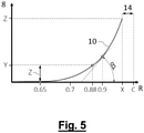
- FIG. 12 is a schematic graph showing a representation of the ground profile, where the X-axis is the roll radius R and the Y-axis is the axis of rotation.
- the ground profile 10 with the non-constant curvature at a distance of 0.9 ⁇ R has a slope ⁇ that is between 0.15° and 2° (0.15° ⁇ ⁇ ⁇ 2.0°), where R is the roll radius or half the roll diameter.
- the profile 10 has a profile height Y of 0.88 ⁇ R between 0.00007 ⁇ R and 0.0020xR (0.00007xR ⁇ Y ⁇ 0.0020xR).
- the profile height is a distance from the profile to a reference value in the direction of the axis of rotation 8 of the roller 1, the reference value being 0.65 ⁇ R in the roller described above.
- the maximum profile height Z at a radial distance X is between 0.0002xR and 0.0065 ⁇ R (0.0002 ⁇ R ⁇ Z ⁇ 0.0065 ⁇ R).
- transition area 14 or edge trimming area of the roll 1 starts at a value X that is between 0.8900xR and 0.9680xR (0.8900 ⁇ R ⁇ X ⁇ 0.9680xR) and ends at a value C that is between 0 .9940xR and 0.9994xR (0.9940 ⁇ R ⁇ C ⁇ 0.9994 ⁇ R).
- a trough 12 is provided, which is not ground in the illustrated embodiment Surface area is formed and thus forms at least one unground surface area radially inside the ground surface.
- This trough 12 can be used, for example, to hold the roller 1 captively on or in a cage (not shown) during assembly.
- the trough 12 can also be ground and/or a non-ground surface area can be provided radially outside the ground surface, ie outside the ground profile 10 , for example in the transition area 14 to the running surface 6 .
- FIG. 3 shows an arrangement 20 with a grinding tool 22 and a roller 1 for a roller bearing, wherein the in the 3 shown roller 1 is designed as a cylindrical roller.
- 4 shows a section X of the arrangement.
- the grinding tool 22 has an axis of rotation 24 and the roller 1 has an axis of rotation 8, the grinding tool 22 and the roller 1 being rotatable relative to one another about their respective axes of rotation 8, 24. Furthermore, the grinding tool 22 and the roller 1 can also be movable relative to one another.
- the directions of rotation of the axes of rotation 8, 24 are preferably selected in such a way that in the contact area of the grinding tool 22 and the roller 1, an opposing movement is carried out.
- the axis of rotation 24 of the grinding tool 22 and the axis of rotation 8 of the roller 1 enclose an angle ⁇ , which can assume a value between 0° and 90°, in particular between 25° and 75°.
- angle ⁇ between the axis of rotation 24 of the grinding tool 22 and the axis of rotation 8 of the roller 1 can be adjustable depending on the profile to be ground.
- the grinding tool 22 has the shape of a truncated cone in cross section and has a grinding surface 26 which is formed on a lateral surface of the truncated cone.
- Abrasive surface 26 has a coating of a nickel matrix with embedded cubic boron nitride (also called CBN) abrasive particles, wherein the abrasive particle size may range between 20 and 100 microns, preferably 50 ⁇ 20 microns, and most preferably 46 ⁇ 2 microns.
- grinding particles made of diamond can also be embedded in the grinding surface 26 .
- the grinding tool 22 can have a base body (not shown) on which the coating is formed.
- the base body Metal for example steel, be formed.
- the base body is preferably very stiff and preferably has a Young's modulus of more than 100 GPa.
- the grinding surface 26 is provided with a profile which is complementary to the profile to be formed.
- the grinding surface 26 on the truncated cone has a first, larger diameter D1 and a second, smaller diameter D2.
- the grinding tool 22 is arranged on the roller 1 in such a way that the first diameter D1 contacts the roller 1 radially further inwards at a roller radius r1 and the second diameter D2 contacts the roller further radially outwards at a roller radius r2 (see Fig 4 ).
- the roller 1 and the grinding tool 22 when the roller 1 and the grinding tool 22 be made possible to each other that the relative rotational speeds of the smaller roller radius r1 and the larger grinding tool diameter D1 or the larger roller radius r2 and the smaller grinding tool diameter D2 equalize, so that a difference, especially along the contact area, becomes smaller and the relative rotational speed can be minimized .
- the area in which the grinding tool 22 and the roller 1 touch essentially corresponds to the grinding area.
- the design of the ground profile 10 is all the more precise the smaller the area of the contact area turns out to be.
- a roller for a roller bearing is provided with a ground end face profile, which has lower friction under an axial load and, as a result, has a higher axial load capacity.
- the grinding enables shorter processing times and thus a more efficient production of the end face profiling, especially compared to other processing methods such as hard turning.
Landscapes
- Engineering & Computer Science (AREA)
- General Engineering & Computer Science (AREA)
- Mechanical Engineering (AREA)
- Rolling Contact Bearings (AREA)
- Grinding Of Cylindrical And Plane Surfaces (AREA)
Abstract
Description
- Vorliegende Erfindung betrifft eine Rolle für ein Rollenlager gemäß dem Oberbegriff von Patentanspruch 1. Des Weiteren betrifft die Erfindung eine Anordnung mit einem Schleifwerkzeug und einer Rolle für ein Rollenlager sowie ein Verfahren zum Herstellen einer Rolle für ein Rollenlager.
- Rollen für Rollenlager haben üblicherweise an ihren jeweiligen Stirnseiten ein gerades Profil, d.h. die Stirnseiten sind weder nach innen noch nach außen gewölbt. Allerdings kann es bei bestimmten Anwendungen vorkommen, dass ein gerades Stirnseitenprofil zu einer hohen Reibung und damit zu hohen Temperaturen führt. Zudem kann sich bei gerade geschliffenen Stirnseiten, das heißt Stirnseiten, die senkrecht zu der Rollenachse verlaufen, ein ungünstiger Rolle-Bord Kontakt ergeben, was unter Axialbelastung zu erhöhter Reibung, Verschleiß bzw. Lagerschäden führen kann. Ferner sind Rollen mit einem geschliffenen Stirnseitenprofil mit einer konstanten, sphärischen Krümmung bekannt, die allerdings den Nachteil haben, dass sie sehr genau gefertigt werden müssen, um kritische Betriebszustände, wie beispielsweise Kantenläufer oder Kontaktellipsenabschneidungen zu verhindern.
- Es ist deshalb Aufgabe vorliegender Erfindung, eine Rolle mit einem verbesserten Stirnseitenprofil und einer verbesserten axialen Tragfähigkeit bereitzustellen.
- Diese Aufgabe wird durch eine Rolle für ein Rollenlager gemäß Patentanspruch 1, einer Anordnung mit einem Schleifwerkzeug und einer Rolle für ein Rollenlager gemäß Patentanspruch 6 sowie ein Verfahren zum Herstellen einer Rolle für ein Rollenlager gemäß Patentanspruch 14 gelöst.
- Im Folgenden wird eine Rolle für Rollenlager mit zwei Stirnflächen und einer Lauffläche beschrieben. Um eine geringere Reibung bei einer Axialbelastung aufzuweisen, weist mindestens eine Stirnfläche ein zumindest teilweise geschliffenes Profil mit einer nicht-konstanten Krümmung auf. Ein mit einer solchen Rolle ausgerüstetes Rollenlager kann insbesondere eine höhere axiale Tragkraft aufweisen und beispielsweise als Radsatzlager, Getriebelager, Fahrmotorenlager von Schienenfahrzeugen, Windkraftlager, Walzwerkslager eingesetzt werden.
- Unter einer nicht-konstanten Krümmung wird eine Krümmung einer Kurve verstanden, deren Krümmungsradius entlang des Verlaufs der Kurve nicht konstant ist, sondern sich verändert. Beispielsweise kann die Krümmung der Kurve, die dem geschliffenen Profil der Stirnfläche entspricht und von einem Startpunkt zu einem Endpunkt verläuft, mit zunehmendem Abstand vom Startpunkt stärker oder schwächer werden.
- Gemäß einem weiteren Ausführungsbeispiels ist die Krümmung entlang einer in radialer Richtung verlaufenden Kurve bestimmt. Bevorzugt ist die Krümmung eine logarithmische Krümmung und/oder das Profil ist ein torusballiges Profil. Ein Stirnflächenprofil mit einer logarithmischen Krümmung und/oder ein torusballiges Profil ermöglicht, Kantenläufer zu vermeiden und eine Reibung im Stirnseitenkontakt von Rollenlagern zu reduzieren.
- Bei der Rolle kann es sich insbesondere um eine Kegelrolle handeln, die entsprechend in einem Kegelrollenlager verwendet wird. Bevorzugt läuft die Stirnfläche mit dem zumindest teilweise geschliffenen Profil an einem Führungsbord des Rollenlagers an. Im Fall einer Kegelrolle, die eine erste Stirnfläche mit einem größeren Durchmesser und eine zweite Stirnfläche mit einem kleineren Durchmesser aufweist, bildet die Stirnfläche mit dem größeren Durchmesser eine Führungsbordlauffläche, und die Stirnfläche mit dem kleineren Durchmesser bildet eine Haltebordlauffläche. Wie oben erwähnt, ist zumindest die Führungsbordlauffläche zumindest teilweise geschliffen und weist eine nicht-konstante Krümmung auf. Die Haltebordlauffläche kann ein planes, ein konstant gekrümmtes oder ein nicht-konstant gekrümmtes Profil aufweisen und beispielsweise geschliffen, hartgedreht oder durch einen anderen Herstellungsmechanismus hergestellt sein.
- Dabei ermöglicht Schleifen, das Profil mit der nicht-konstanten Krümmung im Vergleich zu anderen Bearbeitungsverfahren, wie beispielsweise Hartdrehen oder Erodieren, in kürzeren Bearbeitungszeiten auszubilden und damit eine effizientere Herstellung der Stirnflächenprofilierung zu ermöglichen. Ferner ist es möglich durch Schleifen, auch kleinere Wälzkörper mit einem Profil mit einer nicht-konstanten Krümmung zu versehen. Ferner wird unter dem Ausdruck "geschliffenes Profil" ein Profil verstanden, das durch Schleifen ausgebildet ist, und dessen Form im Wesentlichen durch das Schleifen bestimmt ist. Mit anderen Worten wird unter einem geschliffenen Profil insbesondere kein Profil verstanden, das durch ein anderes Fertigungsverfahren, beispielsweise durch Hartdrehen, ausgebildet ist, und anschließend durch Behebung von Unebenheiten einem Gleitschleifprozess, wie beispielsweise Trommeln, unterzogen wird.
- Bevorzugt ist das geschliffene Profil am Übergang von der Stirnfläche zu einer Lauffläche der Rolle ausgebildet. Insbesondere kann das zumindest teilweise geschliffen Profil der Stirnseite über eine, vorzugsweise ungeschliffene, Kantenkürzung in ein Profil übergehen, das auf der Lauffläche der Rolle ausgebildet ist. Dadurch kann eine Reibung am Übergang von der Stirnfläche zu einer Lauffläche der Rolle am Bord reduziert werden, wodurch die durch die Reibung erzeugte Temperatur reduziert und so der Verschleiß der Rolle verringert und die Gebrauchsdauer der Rolle und damit des Rollenlagers erhöht werden kann. Weiterhin ist vorteilhaft, wenn die Lauffläche der Rolle ebenfalls geschliffen ist. Vorzugsweise weist das Profil, das auf der Lauffläche der Rolle ausgebildet ist, ausgehend von der Kantenkürzung eine nicht konstante Krümmung auf. Höchstvorzugsweise ist die Krümmung eine logarithmische Krümmung und/oder das Profil ist ein torusballiges Profil.
- Gemäß einem bevorzugten Ausführungsbeispiel hat das Profil bei 0,9×R eine Steigung β, die zwischen 0,15° und 2° (0,15° ≤ β ≤ 2,0°) liegt, wobei R der Rollenradius ist. Dadurch kann vorteilhafterweise eine tangentiale Anlage der Rolle an einem Bord eines Wälzlagers erzielt und insbesondere ein Kantenlaufen der Rolle verhindert werden.
- Bevorzugt liegt eine Profilhöhe Y bei 0.88×R zwischen 0,00007xR und 0,0020xR (0,00007×R ≤ Y ≤ 0,0020×R). Vorzugsweise kann eine maximale Profilhöhe Z an einem radialen Abstand X zwischen 0,0002xR und 0,0065×R (0,0002×R ≤ Z ≤ 0,0065×R) liegen. Dabei wird unter dem Begriff Profilhöhe ein Abstand von dem Profil zu einem Referenzwert in Richtung der Rollenachse oder Rotationsachse verstanden. Bei der voranstehend beschriebenen Rolle liegt der Referenzwert bei 0.65 ×R. Bevorzugt beginnt der Kantenkürzungsbereich bei einem Wert X, der zwischen 0,8900xR und 0,9680xR (0,8900xR ≤ X ≤ 0,9680xR) liegt, und endet bei einem Wert C, der zwischen 0,9940xR und 0.9994xR (0,9940×R ≤ C ≤ 0.9994xR) liegt, wobei vorzugsweise im Anschluss an die Kantenkürzung ein Laufbahnprofil ausgebildet ist.
- Gemäß einem weiteren Ausführungsbeispiel weist die Rolle radial innerhalb der geschliffenen Fläche zumindest einen ungeschliffenen Flächenbereich auf. Der ungeschliffene Flächenbereich kann beispielsweise als eine Mulde, ein sogenannter Dimpel, im Bereich der geschliffenen Fläche ausgebildet sein. Diese Mulde bzw. der Dimpel kann beispielsweise dazu dienen, die Rolle während der Montage verliersicher an bzw. in einem Käfig zu halten. Alternativ oder zusätzlich kann der nicht geschliffene Flächenbereich auch radial außerhalb der geschliffenen Fläche, z. B. am Übergang zur Laufbahn oder an einer Kante vorgesehen sein.
- Gemäß einem weiteren Aspekt wird eine Anordnung mit einem Schleifwerkzeug und einer voranstehend beschriebenen Rolle für ein Rollenlager bereitgestellt, wobei das Schleifwerkzeug und die Rolle relativ zueinander rotierbar/bewegbar sind. Dabei ist das Schleifwerkzeug derart ausgebildet, dass es das geschliffene Profil ausbildet, und/oder das Schleifwerkzeug und die Rolle sind derart zueinander bewegbar, dass das geschliffene Profil ausbildbar ist. Beispielsweise können das Schleifwerkzeug und die Rolle zueinander verkippbar sein, um das geschliffene Profil auszubilden. Alternativ oder zusätzlich kann das Schleifwerkzeug ein zu dem an der Rolle auszubildenden Profil komplementäres Profil aufweisen.
- Gemäß einem weiteren bevorzugten Ausführungsbeispiel sind das Schleifwerkzeug und die Rolle derart zueinander angeordnet, dass sie im Wesentlichen entlang eines linienförmigen Kontaktbereich zusammenwirken. Der Kontaktbereich entspricht dabei im Wesentlichen dem Schleifbereich und bildet grob gesprochen eine Linie, entlang derer sich die Rolle und das Schleifwerkzeug berühren. Im Allgemeinen weist der Kontaktbereich aber eine gewisse Fläche auf, wobei eine präzisere Ausgestaltung des geschliffenen Profils umso besser ist je kleiner die Fläche des Kontaktbereichs ausfällt. Beispielsweise kann ein flächiges Profil dadurch erhalten werden kann, dass eine radial verlaufende Kurve, die die nicht-konstante Krümmung bestimmt, um die Rotationsachse gedreht wird. Durch das Drehen der radial verlaufenden Kurve um die Rotationsachse erhält man ein flächiges Profil, das in der radialen Richtung die nicht-konstante Krümmung hat.
- Gemäß einem weiteren Ausführungsbeispiel rotiert das Schleifwerkzeug entlang einer Rotationsachse und/oder die Rolle rotiert entlang einer Rotationsachse, wobei insbesondere die Drehrichtungen der Rotationsachsen derart gewählt sind, dass im Kontaktbereich eine gegenläufige Bewegung ausgeführt wird. Dadurch kann beispielsweise die Effizienz Schleifens verbessert werden.
- Weiterhin kann die Rotationsachse des Schleifwerkzeugs und die Rotationsachse der Rolle einen Winkel einschließen, der einen Wert zwischen 0° und 90°, insbesondere zwischen 25° und 75°, annimmt. Dabei kann der Winkel zwischen der Rotationsachse des Schleifwerkzeugs und der Rotationsachse der Rolle abhängig von dem zu schleifenden Profil einstellbar sein.
- Gemäß einem weiteren Ausführungsbeispiel weist das Schleifwerkzeug im Querschnitt die Form eines Kegelstumpfes auf und weist weiterhin eine Schleiffläche auf, die auf der Mantelfläche des Kegelstumpfes ausgebildet ist, wobei insbesondere die Mantelfläche das komplementäre Profil aufweist. Auf diese Weise kann das zu schleifende Profil einfach auf der Rolle ausgebildet werden.
- Bevorzugt weist die Schleiffläche am Kegelstumpf einen ersten größeren und einen zweiten kleineren Durchmesser auf und das Schleifwerkzeug ist derart an der Rolle angeordnet, dass der erste größere Durchmesser der Schleiffläche die Rolle radial weiter innen, d.h. an einem kleineren Rollendurchmesser, kontaktiert, und der zweite kleinere Durchmesser der Schleiffläche die Rolle radial weiter außen, d.h. an einem größeren Rollendurchmesser, kontaktiert. Dadurch kann bei einer gegenläufigen Rotation der Rolle und des Schleifwerkzeugs ermöglicht werden, dass sich die Rotationsgeschwindigkeiten des kleineren Rollendurchmessers und des größeren Schleifwerkzeugdurchmesser bzw. des größeren Rollendurchmessers und des kleineren Schleifwerkzeugdurchmesser angleichen, so dass ein Unterschied der Relativgeschwindigkeiten, insbesondere im Bereich des Kontaktbereiches, geringer wird.
- Gemäß einer weiteren Ausführungsform hat die Schleiffläche eine Beschichtung aus einer Nickelmatrix mit eingebetteten Schleifpartikel, insbesondere kubisches Bornitrid (auch CBN genannt) und/oder Diamant, wobei eine Korngröße der Schleifpartikel im Bereich zwischen 20 und 100µm liegt. Bevorzugt kann die Korngröße 50±20µm, noch bevorzugter 46±2µm sein. Weiterhin kann das Schleifwerkzeug einen Grundkörper aufweisen, auf dem die Beschichtung ausgebildet ist. Insbesondere kann der Grundkörper aus Metall, zum Beispiel Stahl, gebildet sein. Vorzugsweise ist der Grundkörper sehr steif und hat bevorzugt ein Young'sches Modul von mehr als 100 GPa.
- CBN, oder kubisches Bornitrid, ist nach Diamant das zweithärteste bekannte Material. Während Diamant aus reinem Kohlenstoff besteht, der in einer engen dreidimensionalen Matrix angeordnet ist, verfügt CBN zwar über die gleiche dreidimensionale Matrix, die jedoch aus Bor- und Stickstoffatomen besteht. Aufgrund der komplexen Atomstruktur ist bei CBN eine größere Anzahl von Kornformen als zum Beispiel bei Diamant möglich. Die möglichen Kornformen können sich von einer Oktaeder- bis hin zu einer Würfelform, oder auch von einer Oktaeder- bis hin zu einer Tetraederform erstrecken. Weiterhin hat CBN eine hohe thermische Leitfähigkeit, einen niedrigen Reibungskoeffizienten, und ein spezifisches Gewicht von 3,48 g/cm3.
- Der zunehmende Einsatz von verschleißfesteren und somit schwer spanbaren Stahllegierungen und die parallel geforderten Leistungssteigerungen und Qualitätsanforderungen führten maschinen- und schleifscheibenseitig zu Weiterentwicklungen. Sobald nämlich bei dem zu bearbeitenden Material die Legierungszusätze in eine Karbidform übergehen, wie das bei pulvermetallurgischen Stählen der Fall ist, kommen konventionelle Schleifmittel wie Korunde (Al2O3) schnell an ihre Leistungsgrenze (Knoop'sche Härte von 2.200) und der Einsatz von CBN mit einer Knoop'sehen Härte von 4.500 ist mehr als gerechtfertigt. Zudem hat CBN gegenüber Al2O3 Vorteile in Bezug auf die Wärmeleitfähigkeit und weist somit einen kühleren Schliff auf.
- Abhängig von dem zu schleifenden Material hat CBN zudem den Vorteil, dass es im Gegensatz zu Diamant keinen Kohlenstoff aufweist, der in das zu schleifende Material, insbesondere die Stahllegierungen, diffundiert und diese dadurch in ihren Materialeigenschaften verändern kann. CBN hat eine hohe Lebensdauer und ausgezeichnete Materialabtragungsraten und wird vor allem in Gebieten eingesetzt, die üblicherweise kurze Schleifzykluszeiten und vollautomatisierte Fertigungen aufweisen. Insbesondere pulvermetallurgische oder hochlegierte Werkzeugstähle sind darüber hinaus mit konventionellen Schleifmitteln oftmals nicht mehr wirtschaftlich schleifbar.
- Gemäß einer weiteren Ausführungsform sind die eingebetteten Schleifpartikel crushiert. Unter "Crushieren" (engl. "Brechen") versteht man in der Schleiftechnik das Brechen der Kornspitzen, um die Formgenauigkeit und die Schleiffreudigkeit zu erhöhen. Dies geschieht mittels einer Hartmetallrolle, die rotierend und bahngesteuert die ebenfalls mit gleicher Umfangsgeschwindigkeit rotierende Schleiffläche abfährt und überstehende, von der Profilinie abweichende, Kornspitzen auf genaues Maß bricht. Bei diesem Prozess sollte eine Relativgeschwindigkeit zwischen den beiden Umfangsgeschwindigkeiten der Hartmetallrolle und der Schleiffläche so klein wie möglich sein. Crushierte Schleifpartikel ermöglichen insbesondere das Schleifen von hochgenauen Profilen und Oberflächenqualitäten. Alternativ können die eingebetteten Schleifpartikel auch nicht-crushiert sein.
- Gemäß einem weiteren Aspekt der Erfindung wird ein Verfahren zum Herstellen einer Rolle für ein Rollenlager, wie voranstehend beschrieben, bereitgestellt, wobei insbesondere eine voranstehend beschriebene Anordnung verwendet wird.
- Insbesondere kann das Verfahren die folgenden Schritte aufweisen:
- Bereitstellen einer Rolle für ein Rollenlager mit zwei Stirnflächen und einer Lauffläche, wobei die Rolle ein definiertes Aufmaß auf ihre Abmessungen hat, und
- Schleifen von zumindest einer Stirnfläche der Rolle mit einem Schleifwerkzeug, so dass die mindestens eine Stirnfläche ein zumindest teilweise geschliffenes Profil mit einer nicht-konstanten Krümmung aufweist.
- Insbesondere kann die Rolle das Aufmaß auf ihre Rollenlänge haben. Unter einer Rollenlänge versteht man die Länge der Rolle zwischen den beiden Stirnflächen entlang der Rotationsachse. Das Aufmaß beträgt beispielsweise die ein- bis vierfache Höhe des gewünschten Profils. Die Höhe des Profils entspricht dabei der axialen Erstreckung entlang des geschliffenen Profils in Axialrichtung der Rolle. Dabei kann das Aufmaß im Bereich der Rotationsachse der Rolle geringer ausfallen als am Übergang zur Lauffläche. Zum Beispiel kann das Aufmaß in der Mitte 30µm und am Übergang zur Lauffläche 50 µm betragen.
- Dabei kann die bereitgestellte Rolle bereits eine Grundform der gewünschten Rollen aufweisen. Beispielsweise kann die Rolle eine Kegelform, eine Zylinderform, oder dergleichen aufweisen. Die Grundform kann durch Gießen und/oder mechanisches Bearbeiten aus Rohlingen gebildet sein.
- Bevorzugt ist die bereitgestellte Rolle bereits inklusive der zwei Stirnseiten und/oder der Lauffläche gehärtet. Weiterhin kann die bereitgestellte Rolle vor dem Schleifen des Stirnseitenprofils vorgeschliffen und/oder hartgedreht werden. Dies kann vorteilhaft sein, um eine plane Oberfläche bereitzustellen. Beispielsweise kann beim anschließenden Schleifen des Stirnflächenprofils das bereitgestellte Aufmaß teilweise und/oder vollständig weggeschliffen werden, um das Stirnseitenprofil zu erhalten.
- Bevorzugt werden die Stirnflächen vor den Laufflächen geschliffen. Beispielsweise kann eine vorgeschliffene Rolle zunächst mit den gewünschten Stirnflächenprofilen versehen werden und im Anschluss an den profilgebenden Schleifprozess kann ein Endbearbeitungsverfahren zur Oberflächenveredelung, beispielsweise ein Polieren, ein Honen, ein Läppen, und/oder ein Gleitschleifen, sowie ein Schleifen der Lauffläche stattfinden.
- Gemäß einer weiteren Ausführungsform umfasst das Verfahren ein Drehen einer Mulde bzw. des Dimpels im Bereich einer Rotationsachse der Rolle, wobei die Mulde einen definierten Durchmesser aufweist. Bevorzugt kann die Mulde vor dem Schleifen der Stirnflächen geformt werden. Beispielweise kann der definierte Durchmesser der Mulde abhängig von einem Rollendurchmesser sein. Bevorzugt ist der Durchmesser der Mulde kleiner als das 0,65-fache des Rollendurchmessers. Dies ermöglicht eine flexible Halterung der Rolle an dem Käfig während der Montage.
- Weitere Vorteile und vorteilhafte Ausführungsformen sind in der Beschreibung, den Zeichnungen und den Ansprüchen angegeben. Dabei sind insbesondere die in der Beschreibung und in den Zeichnungen angegebenen Kombinationen der Merkmale rein exemplarisch, so dass die Merkmale auch einzeln oder anders kombiniert vorliegen können.
- Im Folgenden soll die Erfindung anhand von in den Zeichnungen dargestellten Ausführungsbeispielen näher beschrieben werden. Dabei sind die Ausführungsbeispiele und die in den Ausführungsbeispielen gezeigten Kombinationen rein exemplarisch und sollen nicht den Schutzbereich der Erfindung festlegen. Dieser wird allein durch die anhängigen Ansprüche definiert.
- Es zeigen:
-
Fig. 1 : zeigt eine Rolle für ein Rollenlager gemäß einer Ausführungsform, -
Fig. 2 : zeigt einen Ausschnitt A der Rolle ausFig. 1 , -
Fig. 3 : zeigt eine Anordnung mit einem Schleifwerkzeug und einer Rolle für ein Rollenlager gemäß einer weiteren Ausführungsform, -
Fig. 4 : zeigt einen Ausschnitt X der Anordnung ausFig. 3 , und -
Fig. 5 : zeigt einen schematischen Graph, der eine Darstellung des geschliffenen Profils der Rolle ausFig. 1 zeigt. - Im Folgenden werden gleiche oder funktionell gleichwirkende Elemente mit denselben Bezugszeichen gekennzeichnet.
-
Fig. 1 zeigt eine Rolle 1 für ein Rollenlager, die im dargestellten Ausführungsbeispiel als Kegelrolle ausgebildet ist, die in einem Kegelrollenlager verwendet wird.Fig. 2 zeigt einen Ausschnitt A eines Profils der Rolle 1 an einer ihrer Stirnflächen 2. Die Rolle kann alternativ auch eine andere Form, beispielsweise eine Zylinderform, haben. Die Rolle 1 ist mit zwei Stirnflächen 2, 4 und einer Lauffläche 6 versehen, wobei die Rolle 1 dazu ausgelegt ist, um eine Rotationsache 8 zu rotieren. Dabei hat im Fall der gezeigten Kegelrolle die Stirnfläche 4 einen kleineren Durchmesser und die Stirnfläche 2 einen größeren Durchmesser, wobei insbesondere die Stirnfläche 4 an einem Führungsbord (nicht gezeigt) des Lagers anläuft und die Stirnfläche 2 ein Haltebord (nicht gezeigt) kontaktieren kann. - Um eine geringere Reibung bei einer Axialbelastung aufzuweisen und dadurch ein Kantenlaufen zu verhindern, weist die Stirnfläche 2 ein zumindest teilweise geschliffenes Profil 10 auf. Das geschliffene Profil 10 ist in
Fig. 2 durch eine schraffierte Fläche dargestellt. Das Profil 10 hat eine nicht-konstanten Krümmung, wobei die Krümmung entlang einer in radialer Richtung verlaufenden Kurve bestimmt ist und beispielsweise eine logarithmische Krümmung ist. Alternativ oder zusätzlich kann das geschliffene Profil 10 eine torusballiges Form haben. Das geschliffene Profil kann beispielsweise bis zu einem Übergangsbereich 14 von der Stirnfläche 2 zu der Lauffläche 6 der Rolle 1 ausgebildet sein. Insbesondere kann der Übergangsbereich 14 als eine vorzugsweise ungeschliffene Kantenkürzung ausgebildet sein, die in ein auf der Lauffläche 6 der Rolle 1 ausgebildetes Profil übergeht. Ferner kann das Profil, das auf der Lauffläche 6 der Rolle 1 ausgebildet ist, ausgehend von der Kantenkürzung ebenfalls eine nicht konstante Krümmung aufweisen. Beispielsweise kann das Profil der Lauffläche 6 der Rolle 1 eine logarithmische Krümmung aufweisen und/oder als ein torusballiges Profil ausgebildet sein. -
Fig. 5 ist ein schematischer Graph, der eine Darstellung des geschliffenen Profils zeigt, wobei auf der X-Achse der Rollenradius R und auf der Y-Achse die Rotationsachse aufgetragen ist. Das geschliffene Profil 10 mit der nicht-konstanten Krümmung hat bei einem Abstand von 0,9×R eine Steigung β, die zwischen 0,15° und 2° (0,15° ≤ β ≤ 2,0°) liegt, wobei R der Rollenradius bzw. der halbe Rollendurchmesser ist. Dadurch kann vorteilhafterweise eine tangentiale Anlage der Rolle 1 an einem Bord eines Wälzlagers erzielt und insbesondere ein Kantenlaufen der Rolle 1 verhindert werden. - Ferner liegt bei dem Profil 10 eine Profilhöhe Y bei 0.88×R zwischen 0, 00007×R und 0,0020xR (0,00007xR ≤ Y ≤ 0,0020xR). Die Profilhöhe ist ein Abstand von dem Profil zu einem Referenzwert in Richtung der Rotationsachse 8 der Rolle 1, wobei bei der voranstehend beschriebenen Rolle der Referenzwert bei 0.65 ×R liegt. Die maximale Profilhöhe Z bei einem radialen Abstand X liegt zwischen 0,0002xR und 0,0065×R (0,0002×R ≤ Z ≤ 0,0065 ×R).
- Des Weiteren beginnt der Übergangsbereich 14 oder Kantenkürzungsbereich der Rolle 1 bei einem Wert X, der zwischen 0,8900xR und 0,9680xR (0,8900×R ≤ X ≤ 0,9680xR) liegt, und endet bei einem Wert C, der zwischen 0,9940xR und 0.9994xR (0,9940×R ≤ C ≤ 0.9994×R) liegt.
- Weiterhin zeigen
Fig. 1 und 2 , dass im Bereich der Rotationsachse 8 in der Seitenfläche 2 eine Mulde 12 vorgesehen ist, die in dem dargestellten Ausführungsbeispiel als nicht geschliffener Flächenbereich ausgebildet ist und somit radial innerhalb der geschliffenen Fläche zumindest einen ungeschliffenen Flächenbereich ausbildet. Diese Mulde 12 kann beispielsweise dazu dienen, die Rolle 1 während der Montage verliersicher an bzw. in einem Käfig (nicht gezeigt) zu halten. Alternativ oder zusätzlich kann die Mulde 12 auch geschliffen ausgebildet sein und/oder ein nicht-geschliffener Flächenbereich radial außerhalb der geschliffenen Fläche, d.h. außerhalb der geschliffenen Profils 10, beispielsweise im Übergangbereich 14 zu der Lauffläche 6, vorgesehen sein. -
Fig. 3 zeigt eine Anordnung 20 mit einem Schleifwerkzeug 22 und einer Rolle 1 für ein Rollenlager, wobei die in derFig. 3 gezeigte Rolle 1 als Zylinderrolle ausgebildet ist.Fig. 4 zeigt einen Ausschnitt X der Anordnung. - Das Schleifwerkzeug 22 hat eine Rotationsachse 24 und die Rolle 1 hat eine Rotationsachse 8, wobei das Schleifwerkzeug 22 und die Rolle 1 relativ zueinander um ihre jeweiligen Rotationsachsen 8, 24 rotierbar sind. Ferner können das Schleifwerkzeug 22 und die Rolle 1 auch relativ zueinander bewegbar sein. Bevorzugt sind die Drehrichtungen der Rotationsachsen 8, 24 derart gewählt sind, dass im Kontaktbereich von Schleifwerkzeug 22 und Rolle 1 eine gegenläufige Bewegung ausgeführt wird.
- Die Rotationsachse 24 des Schleifwerkzeugs 22 und die Rotationsachse 8 der Rolle 1 schließen einen Winkel α ein, der einen Wert zwischen 0° und 90°, insbesondere zwischen 25° und 75°, annehmen kann. Zudem kann der Winkel α zwischen der Rotationsachse 24 des Schleifwerkzeugs 22 und der Rotationsachse 8 der Rolle 1 abhängig von dem zu schleifenden Profil einstellbar sein.
- In dem dargestellten Ausführungsbeispiel hat das Schleifwerkzeug 22 im Querschnitt die Form eines Kegelstumpfes und weist eine Schleiffläche 26 auf, die auf einer Mantelfläche des Kegelstumpfes ausgebildet ist. Die Schleiffläche 26 hat eine Beschichtung aus einer Nickelmatrix mit eingebetteten Schleifpartikel aus kubischen Bornitrid (auch CBN genannt), wobei eine Korngröße der Schleifpartikel im Bereich zwischen 20 und 100µm liegt, und bevorzugt 50±20µm und am bevorzugsten 46±2µm sein kann. Alternativ oder zusätzlich können auch Schleifpartikel aus Diamant in der Schleiffläche 26 eingebettet sein. Weiterhin kann das Schleifwerkzeug 22 einen Grundkörper (nicht dargestellt) aufweisen, auf dem die Beschichtung ausgebildet ist. Insbesondere kann der Grundkörper aus Metall, zum Beispiel Stahl, gebildet sein. Vorzugsweise ist der Grundkörper sehr steif und hat bevorzugt ein Young'sches Modul von mehr als 100 GPa.
- Um das geschliffene Profil 10 auszubilden, ist die Schleiffläche 26 mit einem zu dem auszubildenden Profil komplementären Profil versehen. Dabei weist die Schleiffläche 26 am Kegelstumpf einen ersten größeren Durchmesser D1 und einen zweiten kleineren Durchmesser D2 auf. Ferner ist das Schleifwerkzeug 22 derart an der Rolle 1 angeordnet, dass der erste Durchmesser D1 die Rolle 1 radial weiter innen bei einem Rollenradius r1 kontaktiert und der zweite Durchmesser D2 die Rolle radial weiter außen bei einem Rollenradius r2 kontaktiert (siehe
Fig. 4 ). - Dadurch dass der erste größere Durchmesser D1 die Rolle radial weiter innen, d.h. am Rollenradius r1, kontaktiert und der zweite kleinere Durchmesser D2 die Rolle radial weiter außen, d.h. am größeren Rollenradius r2 kontaktiert, kann bei einer gegenläufigen Rotation der Rolle 1 und des Schleifwerkzeugs 22 zueinander ermöglicht werden, dass sich die relativen Rotationsgeschwindigkeiten des kleineren Rollenradius r1 und des größeren Schleifwerkzeugdurchmessers D1 bzw. des größeren Rollenradius r2 und des kleineren Schleifwerkzeugdurchmesser D2 angleichen, so dass ein Unterschied, insbesondere entlang des Kontaktbereiches, geringer wird und die relative Rotationsgeschwindigkeit minimiert werden kann. Dies erlaubt, dass die Wärmeentwicklung, die beim Schleifen entsteht, zu minimieren. Der Bereich, in dem sich das Schleifwerkzeug 22 und die Rolle 1 berühren, entspricht dabei im Wesentlichen dem Schleifbereich. Dabei ist die Ausgestaltung des geschliffenen Profils 10 umso genauer, je kleiner die Fläche des Kontaktbereichs ausfällt.
- Zusammenfassend wird eine Rolle für ein Rollenlager mit einem geschliffenen Stirnseitenprofil bereitgestellt, das eine geringere Reibung bei einer Axialbelastung und dadurch eine höhere axiale Tragkraft aufweist. Dabei ermöglicht das Schleifen kürzere Bearbeitungszeiten und damit eine effizientere Herstellung der Stirnflächenprofilierung insbesondere im Vergleich zu anderen Bearbeitungsverfahren, wie beispielsweise Hartdrehen. Ferner ist es auch möglich, kleine Wälzkörper mit einem beliebig gekrümmten Profil zu versehen, wodurch eine Verbesserung der Gleitreibung und somit eine Erhöhung der axialen Tragfähigkeit der Wälzkörper gewährleistet wird.
-
- 1
- Rolle
- 2,4
- Stirnfläche
- 6
- Lauffläche
- 8
- Rotationsachse
- 10
- geschliffenes Profil
- 12
- Mulde
- 14
- Übergangsbereich
- 20
- Anordnung
- 22
- Schleifwerkzeug
- 24
- Rotationsachse
- 26
- Schleiffläche
- D1, D2
- Durchmesser
- r1, r2
- Rollenradius
- Z
- maximale Profilhöhe
- Y
- Profilhöhe
- X
- Übergangsbereichsanfang
- C
- Übergangsbereichsende
Claims (15)
- Rolle (1) für ein Rollenlager mit zwei Stirnflächen (2, 4) und einer Lauffläche (6),dadurch gekennzeichnet, dassmindestens eine Stirnfläche (2, 4) ein zumindest teilweise geschliffenes Profil (10) mit einer nicht-konstanten Krümmung aufweist.
- Rolle (1) für Rollenlager gemäß Anspruch 1, wobei das geschliffene Profil (10) am Übergang (14) von Stirnfläche (2, 4) zu Lauffläche (6) ausgebildet ist, wobei vorzugsweise das zumindest teilweise geschliffen Profil (10) der Stirnfläche (2, 4) über eine, vorzugsweise ungeschliffene, Kantenkürzung in ein Profil übergeht, das auf der Lauffläche (6) der Rolle (1) ausgebildet ist.
- Rolle (1) für Rollenlager gemäß einem der vorhergehenden Ansprüche, wobei die Krümmung entlang einer in radialer Richtung verlaufenden Kurve bestimmt ist.
- Rolle (1) für Rollenlager gemäß einem der vorhergehenden Ansprüche, wobei die Krümmung eine logarithmische Krümmung und/oder das Profil ein torusballiges Profil ist.
- Rolle (1) für Rollenlager gemäß einem der vorhergehenden Ansprüche, wobei das Profil (10) bei 0,9×R eine Steigung β hat, die zwischen 0,15° und 2° (0,15° ≤ β ≤ 2,0°) liegt, wobei R der Rollenradius ist.
- Rolle (1) für Rollenlager gemäß einem der vorhergehenden Ansprüche, wobei eine Profilhöhe Y bei 0.88×R zwischen 0,00007xR und 0,0020xR (0,00007×R ≤ Y ≤ 0,0020×R) liegt.
- Rolle (1) für Rollenlager gemäß einem der vorhergehenden Ansprüche, wobei die Rolle (1) radial innerhalb der geschliffenen Fläche zumindest einen ungeschliffenen Flächenbereich (12) aufweist.
- Anordnung (20) mit einem Schleifwerkzeug (22) und einer Rolle (1) für ein Rollenlager gemäß einem der Ansprüche 1 bis 7, wobei das Schleifwerkzeug (22) und die Rolle (1) relativ zueinander rotierbar/bewegbar sind, wobei das Schleifwerkzeug (22) derart ausgebildet ist, dass es das geschliffene Profil (10) ausbildet, und/oder das Schleifwerkzeug (22) und die Rolle (1) derart zueinander bewegbar sind, dass das geschliffene Profil (10) ausbildbar ist.
- Anordnung (20) nach Anspruch 8, wobei das Schleifwerkzeug (22) ein zu dem an der Rolle (1) auszubildenden Profil (10) komplementäres Profil aufweist.
- Anordnung (20) nach Anspruch 8 oder 9, wobei das Schleifwerkzeug (22) und die Rolle (1) derart zueinander angeordnet sind, dass sie im Wesentlichen entlang eines linienförmigen Kontaktbereich zusammenwirken.
- Anordnung (20) nach einem der Ansprüche 8 bis 10, wobei das Schleifwerkzeug (22) entlang einer Rotationsachse (24) rotiert und/oder die Rolle (1) entlang einer Rotationsachse (8) rotiert, wobei insbesondere die Drehrichtungen der Rotationsachsen (8, 24) derart gewählt sind, dass im Kontaktbereich eine gegenläufige Bewegung ausgeführt wird, wobei vorzugsweise die Rotationsachse (24) des Schleifwerkzeugs (22) und die Rotationsachse (8) der Rolle (1) einen Winkel (a) einschließen, der einen Wert zwischen 0° und 90°, insbesondere zwischen 25° und 75°, annimmt.
- Anordnung (20) gemäß einem der Ansprüche 8 bis 11, wobei das Schleifwerkzeug (22) im Querschnitt die Form eines Kegelstumpfes aufweist und weiterhin eine Schleiffläche (26) aufweist, die auf der Mantelfläche des Kegelstumpfes ausgebildet ist, wobei insbesondere die Mantelfläche das komplementäre Profil aufweist.
- Anordnung (20) gemäß Anspruch 12, wobei die Schleiffläche (26) am Kegelstumpf einen ersten größeren und einen zweiten kleineren Durchmesser (D1, D2) aufweist und das Schleifwerkzeug derart an der Rolle angeordnet ist, dass der erste Durchmesser (D1) die Rolle radial weiter innen kontaktiert und der zweite Durchmesser (D2) die Rolle radial weiter außen kontaktiert.
- Anordnung (20) nach einem der Ansprüche 8 bis 13, wobei die Schleiffläche (26) eine Beschichtung aus einer Nickelmatrix mit eingebetteten Schleifpartikel, insbesondere kubisches Bornitrid (auch CBN genannt) und/oder Diamant, hat, wobei eine Korngröße der Schleifpartikel im Bereich zwischen 20 und 100µm liegt.
- Verfahren zum Herstellen einer Rolle (1) für ein Rollenlager nach einem der Ansprüche 1 bis 7, wobei insbesondere eine Anordnung (20) nach einem der Ansprüche 8 bis 14 verwendet wird.
Applications Claiming Priority (1)
| Application Number | Priority Date | Filing Date | Title |
|---|---|---|---|
| DE102020211036.0A DE102020211036B4 (de) | 2020-09-02 | 2020-09-02 | Anordnung mit einem Schleifwerkzeug und einer Rolle für ein Rollenlager sowie Verfahren zum Herstellen einer Rolle für ein Rollenlager |
Publications (2)
| Publication Number | Publication Date |
|---|---|
| EP3964724A1 true EP3964724A1 (de) | 2022-03-09 |
| EP3964724B1 EP3964724B1 (de) | 2023-10-04 |
Family
ID=77519004
Family Applications (1)
| Application Number | Title | Priority Date | Filing Date |
|---|---|---|---|
| EP21193248.8A Active EP3964724B1 (de) | 2020-09-02 | 2021-08-26 | Rolle für rollenlager, anordnung mit einem schleifwerkzeug und einer rolle für ein rollenlager sowie verfahren zum herstellen einer rolle für ein rollenlager |
Country Status (4)
| Country | Link |
|---|---|
| US (1) | US11746826B2 (de) |
| EP (1) | EP3964724B1 (de) |
| CN (1) | CN114198404B (de) |
| DE (1) | DE102020211036B4 (de) |
Families Citing this family (1)
| Publication number | Priority date | Publication date | Assignee | Title |
|---|---|---|---|---|
| EP4620618A4 (de) * | 2024-01-22 | 2026-04-15 | Nsk Ltd | Superfinishing-verfahren, wälzlagerherstellungsverfahren, fahrzeugherstellungsverfahren, maschinenherstellungsverfahren und superfinishing-vorrichtung |
Citations (6)
| Publication number | Priority date | Publication date | Assignee | Title |
|---|---|---|---|---|
| DE505357C (de) * | 1928-12-19 | 1930-08-20 | Timken Roller Bearing Co | Kegelrollenlager mit einer Anlaufrippe |
| DE10230357A1 (de) * | 2001-07-05 | 2003-03-06 | Nsk Ltd | Wälzlager |
| US20030236058A1 (en) * | 2002-04-03 | 2003-12-25 | Nsk Ltd. | Centerless grinding apparatus and centerless grinding method |
| DE102005061102A1 (de) * | 2005-12-21 | 2007-07-05 | Schaeffler Kg | Wälzlager |
| DE102008028164A1 (de) * | 2008-06-12 | 2010-01-07 | Ab Skf | Rolle und Rollenlager mit der Rolle |
| DE102015105511A1 (de) * | 2014-04-16 | 2015-10-22 | Jtekt Corporation | Lagerring für Rollenlager, Rollenlager, und Kraftübertragungsvorrichtung |
Family Cites Families (13)
| Publication number | Priority date | Publication date | Assignee | Title |
|---|---|---|---|---|
| US5752775A (en) * | 1994-08-31 | 1998-05-19 | Ntn Corporation | Roller bearing |
| JP2000087963A (ja) * | 1998-09-16 | 2000-03-28 | Nippon Seiko Kk | ころ軸受 |
| US7097678B2 (en) * | 2003-01-06 | 2006-08-29 | Showa Denko K.K. | Metal-coated cubic boron nitride abrasive grain, production method thereof, and resin bonded grinding wheel |
| JP2004353744A (ja) * | 2003-05-28 | 2004-12-16 | Nsk Ltd | ころ軸受 |
| EP1632685B1 (de) * | 2003-06-12 | 2013-07-10 | NSK Ltd. | Zylindrisches rollenlager |
| DE102005061179A1 (de) * | 2005-12-21 | 2007-06-28 | Schaeffler Kg | Wälzlager und Verfahren zu dessen Herstellung |
| DE102005061103A1 (de) * | 2005-12-21 | 2007-07-05 | Schaeffler Kg | Wälzlager mit verbesserter Bordgeometrie |
| JP5522569B2 (ja) * | 2010-01-26 | 2014-06-18 | Ntn株式会社 | ころの製造方法 |
| DE102011076329B4 (de) * | 2011-05-24 | 2013-11-21 | Aktiebolaget Skf | Geometriekonzept für eine Wälzkörperrolle eines Rollenlagers |
| FR3037519B1 (fr) | 2015-06-17 | 2017-07-28 | Ntn-Snr Roulements | Procede de rectification d'une surface d'un corps roulant pour un palier a roulement |
| JP6965006B2 (ja) | 2017-03-28 | 2021-11-10 | Ntn株式会社 | 円錐ころ軸受 |
| US11053978B2 (en) * | 2017-04-26 | 2021-07-06 | The Timken Company | Non-elliptical contact profile for roller bearing |
| DE102017121861A1 (de) * | 2017-09-21 | 2019-03-21 | Schaeffler Technologies AG & Co. KG | Fertigungsvorrichtung zur Fertigung eines gekrümmten Verlaufs an mindestens einer Stirnfläche einer Rolle und Verfahren zur Fertigung eines gekrümmten Verlaufs an der mindestens einen Stirnfläche mit der Fertigungsvorrichtung |
-
2020
- 2020-09-02 DE DE102020211036.0A patent/DE102020211036B4/de active Active
-
2021
- 2021-08-25 US US17/411,604 patent/US11746826B2/en active Active
- 2021-08-26 EP EP21193248.8A patent/EP3964724B1/de active Active
- 2021-09-02 CN CN202111024938.3A patent/CN114198404B/zh active Active
Patent Citations (6)
| Publication number | Priority date | Publication date | Assignee | Title |
|---|---|---|---|---|
| DE505357C (de) * | 1928-12-19 | 1930-08-20 | Timken Roller Bearing Co | Kegelrollenlager mit einer Anlaufrippe |
| DE10230357A1 (de) * | 2001-07-05 | 2003-03-06 | Nsk Ltd | Wälzlager |
| US20030236058A1 (en) * | 2002-04-03 | 2003-12-25 | Nsk Ltd. | Centerless grinding apparatus and centerless grinding method |
| DE102005061102A1 (de) * | 2005-12-21 | 2007-07-05 | Schaeffler Kg | Wälzlager |
| DE102008028164A1 (de) * | 2008-06-12 | 2010-01-07 | Ab Skf | Rolle und Rollenlager mit der Rolle |
| DE102015105511A1 (de) * | 2014-04-16 | 2015-10-22 | Jtekt Corporation | Lagerring für Rollenlager, Rollenlager, und Kraftübertragungsvorrichtung |
Also Published As
| Publication number | Publication date |
|---|---|
| CN114198404A (zh) | 2022-03-18 |
| DE102020211036A1 (de) | 2022-03-03 |
| DE102020211036B4 (de) | 2022-04-14 |
| US20220065295A1 (en) | 2022-03-03 |
| US11746826B2 (en) | 2023-09-05 |
| EP3964724B1 (de) | 2023-10-04 |
| CN114198404B (zh) | 2026-07-03 |
Similar Documents
| Publication | Publication Date | Title |
|---|---|---|
| DE69418836T2 (de) | Endbearbeitungsverfahren für Lageroberflächen | |
| DE69838522T2 (de) | Hydrodynamisches Gaslager und Verfahren zu dessen Herstellung | |
| DE68919908T2 (de) | Schleifscheibe mit hoher Schlagfestigkeit zum in-situ-Schleifen von Rollen. | |
| DE10210670B4 (de) | Wälzelemente für Wälzlager, Verfahren zu deren Herstellung und Wälzlager | |
| DE10311566B4 (de) | Rollenlagerkäfig und Rollenlager | |
| EP1511590B1 (de) | Fräser mit wiper-radius | |
| EP1253988B1 (de) | Verfahren zur drallfreien spanenden bearbeitung von rotationssymmetrischen flächen | |
| EP1963693B1 (de) | Verfahren zur herstellung eines wälzlagerringes | |
| DE10230357A1 (de) | Wälzlager | |
| EP2094983B1 (de) | Radialwälzlager, insbesondere zur lagerung von wellen in windkraftgetrieben | |
| EP3964724B1 (de) | Rolle für rollenlager, anordnung mit einem schleifwerkzeug und einer rolle für ein rollenlager sowie verfahren zum herstellen einer rolle für ein rollenlager | |
| DE19963897B4 (de) | Verfahren zur drallfreien spanenden Bearbeitung von rotationssymmetrischen Flächen | |
| DE102022120755B4 (de) | Schaftfräser mit Hohlstirn und Verfahren zu seiner Herstellung | |
| WO2019114871A1 (de) | Verfahren zum schleifen von wälzkörpern für ein wälzlager sowie verwendung eines verfahrens | |
| DE3524412C2 (de) | ||
| EP3323541A1 (de) | Verbesserter logarithmischer fräskopf | |
| DE102010045836A1 (de) | Vorrichtung und Verfahren zur Herstellung eines Abrichtwerkzeuges mit Vertiefungen | |
| WO2024200389A1 (de) | Schleifscheibe zum planseitigen und kegelförmigen schleifen von schwer zerspanbaren werkstoffen an rotationssymmetrischen werkstücken | |
| DE112020004434T5 (de) | Kegelrollenlager | |
| EP3966463B1 (de) | Verfahren zur bearbeitung eines lagerrings und zur herstellung eines wälzlagers, sowie wälzlager | |
| DE112020004401T5 (de) | Kegelrollenlager | |
| DE102008030466B3 (de) | Lageranordnung | |
| DE102017104962A1 (de) | Tripodenrolle für ein Gleichlaufgelenk sowie Gleichlaufgelenk mit der Tripodenrolle | |
| EP4248101B1 (de) | Kegelrollenlager | |
| EP3154745B1 (de) | Schleifscheibe |
Legal Events
| Date | Code | Title | Description |
|---|---|---|---|
| PUAI | Public reference made under article 153(3) epc to a published international application that has entered the european phase |
Free format text: ORIGINAL CODE: 0009012 |
|
| STAA | Information on the status of an ep patent application or granted ep patent |
Free format text: STATUS: THE APPLICATION HAS BEEN PUBLISHED |
|
| AK | Designated contracting states |
Kind code of ref document: A1 Designated state(s): AL AT BE BG CH CY CZ DE DK EE ES FI FR GB GR HR HU IE IS IT LI LT LU LV MC MK MT NL NO PL PT RO RS SE SI SK SM TR |
|
| STAA | Information on the status of an ep patent application or granted ep patent |
Free format text: STATUS: REQUEST FOR EXAMINATION WAS MADE |
|
| 17P | Request for examination filed |
Effective date: 20220831 |
|
| RBV | Designated contracting states (corrected) |
Designated state(s): AL AT BE BG CH CY CZ DE DK EE ES FI FR GB GR HR HU IE IS IT LI LT LU LV MC MK MT NL NO PL PT RO RS SE SI SK SM TR |
|
| GRAP | Despatch of communication of intention to grant a patent |
Free format text: ORIGINAL CODE: EPIDOSNIGR1 |
|
| STAA | Information on the status of an ep patent application or granted ep patent |
Free format text: STATUS: GRANT OF PATENT IS INTENDED |
|
| RIC1 | Information provided on ipc code assigned before grant |
Ipc: B24B 1/00 20060101ALI20230331BHEP Ipc: F16C 33/36 20060101AFI20230331BHEP |
|
| INTG | Intention to grant announced |
Effective date: 20230421 |
|
| GRAS | Grant fee paid |
Free format text: ORIGINAL CODE: EPIDOSNIGR3 |
|
| GRAA | (expected) grant |
Free format text: ORIGINAL CODE: 0009210 |
|
| STAA | Information on the status of an ep patent application or granted ep patent |
Free format text: STATUS: THE PATENT HAS BEEN GRANTED |
|
| AK | Designated contracting states |
Kind code of ref document: B1 Designated state(s): AL AT BE BG CH CY CZ DE DK EE ES FI FR GB GR HR HU IE IS IT LI LT LU LV MC MK MT NL NO PL PT RO RS SE SI SK SM TR |
|
| REG | Reference to a national code |
Ref country code: GB Ref legal event code: FG4D Free format text: NOT ENGLISH |
|
| REG | Reference to a national code |
Ref country code: CH Ref legal event code: EP |
|
| REG | Reference to a national code |
Ref country code: DE Ref legal event code: R096 Ref document number: 502021001624 Country of ref document: DE |
|
| REG | Reference to a national code |
Ref country code: IE Ref legal event code: FG4D Free format text: LANGUAGE OF EP DOCUMENT: GERMAN |
|
| P01 | Opt-out of the competence of the unified patent court (upc) registered |
Effective date: 20231026 |
|
| REG | Reference to a national code |
Ref country code: LT Ref legal event code: MG9D |
|
| REG | Reference to a national code |
Ref country code: NL Ref legal event code: MP Effective date: 20231004 |
|
| PG25 | Lapsed in a contracting state [announced via postgrant information from national office to epo] |
Ref country code: NL Free format text: LAPSE BECAUSE OF FAILURE TO SUBMIT A TRANSLATION OF THE DESCRIPTION OR TO PAY THE FEE WITHIN THE PRESCRIBED TIME-LIMIT Effective date: 20231004 |
|
| PG25 | Lapsed in a contracting state [announced via postgrant information from national office to epo] |
Ref country code: GR Free format text: LAPSE BECAUSE OF FAILURE TO SUBMIT A TRANSLATION OF THE DESCRIPTION OR TO PAY THE FEE WITHIN THE PRESCRIBED TIME-LIMIT Effective date: 20240105 |
|
| PG25 | Lapsed in a contracting state [announced via postgrant information from national office to epo] |
Ref country code: IS Free format text: LAPSE BECAUSE OF FAILURE TO SUBMIT A TRANSLATION OF THE DESCRIPTION OR TO PAY THE FEE WITHIN THE PRESCRIBED TIME-LIMIT Effective date: 20240204 |
|
| PG25 | Lapsed in a contracting state [announced via postgrant information from national office to epo] |
Ref country code: LT Free format text: LAPSE BECAUSE OF FAILURE TO SUBMIT A TRANSLATION OF THE DESCRIPTION OR TO PAY THE FEE WITHIN THE PRESCRIBED TIME-LIMIT Effective date: 20231004 |
|
| PG25 | Lapsed in a contracting state [announced via postgrant information from national office to epo] |
Ref country code: ES Free format text: LAPSE BECAUSE OF FAILURE TO SUBMIT A TRANSLATION OF THE DESCRIPTION OR TO PAY THE FEE WITHIN THE PRESCRIBED TIME-LIMIT Effective date: 20231004 |
|
| PG25 | Lapsed in a contracting state [announced via postgrant information from national office to epo] |
Ref country code: LT Free format text: LAPSE BECAUSE OF FAILURE TO SUBMIT A TRANSLATION OF THE DESCRIPTION OR TO PAY THE FEE WITHIN THE PRESCRIBED TIME-LIMIT Effective date: 20231004 Ref country code: IS Free format text: LAPSE BECAUSE OF FAILURE TO SUBMIT A TRANSLATION OF THE DESCRIPTION OR TO PAY THE FEE WITHIN THE PRESCRIBED TIME-LIMIT Effective date: 20240204 Ref country code: GR Free format text: LAPSE BECAUSE OF FAILURE TO SUBMIT A TRANSLATION OF THE DESCRIPTION OR TO PAY THE FEE WITHIN THE PRESCRIBED TIME-LIMIT Effective date: 20240105 Ref country code: ES Free format text: LAPSE BECAUSE OF FAILURE TO SUBMIT A TRANSLATION OF THE DESCRIPTION OR TO PAY THE FEE WITHIN THE PRESCRIBED TIME-LIMIT Effective date: 20231004 Ref country code: BG Free format text: LAPSE BECAUSE OF FAILURE TO SUBMIT A TRANSLATION OF THE DESCRIPTION OR TO PAY THE FEE WITHIN THE PRESCRIBED TIME-LIMIT Effective date: 20240104 Ref country code: PT Free format text: LAPSE BECAUSE OF FAILURE TO SUBMIT A TRANSLATION OF THE DESCRIPTION OR TO PAY THE FEE WITHIN THE PRESCRIBED TIME-LIMIT Effective date: 20240205 |
|
| PG25 | Lapsed in a contracting state [announced via postgrant information from national office to epo] |
Ref country code: SE Free format text: LAPSE BECAUSE OF FAILURE TO SUBMIT A TRANSLATION OF THE DESCRIPTION OR TO PAY THE FEE WITHIN THE PRESCRIBED TIME-LIMIT Effective date: 20231004 Ref country code: RS Free format text: LAPSE BECAUSE OF FAILURE TO SUBMIT A TRANSLATION OF THE DESCRIPTION OR TO PAY THE FEE WITHIN THE PRESCRIBED TIME-LIMIT Effective date: 20231004 Ref country code: PL Free format text: LAPSE BECAUSE OF FAILURE TO SUBMIT A TRANSLATION OF THE DESCRIPTION OR TO PAY THE FEE WITHIN THE PRESCRIBED TIME-LIMIT Effective date: 20231004 Ref country code: NO Free format text: LAPSE BECAUSE OF FAILURE TO SUBMIT A TRANSLATION OF THE DESCRIPTION OR TO PAY THE FEE WITHIN THE PRESCRIBED TIME-LIMIT Effective date: 20240104 Ref country code: LV Free format text: LAPSE BECAUSE OF FAILURE TO SUBMIT A TRANSLATION OF THE DESCRIPTION OR TO PAY THE FEE WITHIN THE PRESCRIBED TIME-LIMIT Effective date: 20231004 Ref country code: HR Free format text: LAPSE BECAUSE OF FAILURE TO SUBMIT A TRANSLATION OF THE DESCRIPTION OR TO PAY THE FEE WITHIN THE PRESCRIBED TIME-LIMIT Effective date: 20231004 |
|
| REG | Reference to a national code |
Ref country code: DE Ref legal event code: R097 Ref document number: 502021001624 Country of ref document: DE |
|
| PG25 | Lapsed in a contracting state [announced via postgrant information from national office to epo] |
Ref country code: DK Free format text: LAPSE BECAUSE OF FAILURE TO SUBMIT A TRANSLATION OF THE DESCRIPTION OR TO PAY THE FEE WITHIN THE PRESCRIBED TIME-LIMIT Effective date: 20231004 |
|
| PG25 | Lapsed in a contracting state [announced via postgrant information from national office to epo] |
Ref country code: SK Free format text: LAPSE BECAUSE OF FAILURE TO SUBMIT A TRANSLATION OF THE DESCRIPTION OR TO PAY THE FEE WITHIN THE PRESCRIBED TIME-LIMIT Effective date: 20231004 |
|
| PG25 | Lapsed in a contracting state [announced via postgrant information from national office to epo] |
Ref country code: SM Free format text: LAPSE BECAUSE OF FAILURE TO SUBMIT A TRANSLATION OF THE DESCRIPTION OR TO PAY THE FEE WITHIN THE PRESCRIBED TIME-LIMIT Effective date: 20231004 Ref country code: SK Free format text: LAPSE BECAUSE OF FAILURE TO SUBMIT A TRANSLATION OF THE DESCRIPTION OR TO PAY THE FEE WITHIN THE PRESCRIBED TIME-LIMIT Effective date: 20231004 Ref country code: RO Free format text: LAPSE BECAUSE OF FAILURE TO SUBMIT A TRANSLATION OF THE DESCRIPTION OR TO PAY THE FEE WITHIN THE PRESCRIBED TIME-LIMIT Effective date: 20231004 Ref country code: IT Free format text: LAPSE BECAUSE OF FAILURE TO SUBMIT A TRANSLATION OF THE DESCRIPTION OR TO PAY THE FEE WITHIN THE PRESCRIBED TIME-LIMIT Effective date: 20231004 Ref country code: EE Free format text: LAPSE BECAUSE OF FAILURE TO SUBMIT A TRANSLATION OF THE DESCRIPTION OR TO PAY THE FEE WITHIN THE PRESCRIBED TIME-LIMIT Effective date: 20231004 Ref country code: DK Free format text: LAPSE BECAUSE OF FAILURE TO SUBMIT A TRANSLATION OF THE DESCRIPTION OR TO PAY THE FEE WITHIN THE PRESCRIBED TIME-LIMIT Effective date: 20231004 |
|
| PLBE | No opposition filed within time limit |
Free format text: ORIGINAL CODE: 0009261 |
|
| STAA | Information on the status of an ep patent application or granted ep patent |
Free format text: STATUS: NO OPPOSITION FILED WITHIN TIME LIMIT |
|
| 26N | No opposition filed |
Effective date: 20240705 |
|
| PG25 | Lapsed in a contracting state [announced via postgrant information from national office to epo] |
Ref country code: SI Free format text: LAPSE BECAUSE OF FAILURE TO SUBMIT A TRANSLATION OF THE DESCRIPTION OR TO PAY THE FEE WITHIN THE PRESCRIBED TIME-LIMIT Effective date: 20231004 |
|
| PG25 | Lapsed in a contracting state [announced via postgrant information from national office to epo] |
Ref country code: SI Free format text: LAPSE BECAUSE OF FAILURE TO SUBMIT A TRANSLATION OF THE DESCRIPTION OR TO PAY THE FEE WITHIN THE PRESCRIBED TIME-LIMIT Effective date: 20231004 |
|
| REG | Reference to a national code |
Ref country code: CH Ref legal event code: PL |
|
| PG25 | Lapsed in a contracting state [announced via postgrant information from national office to epo] |
Ref country code: LU Free format text: LAPSE BECAUSE OF NON-PAYMENT OF DUE FEES Effective date: 20240826 |
|
| PG25 | Lapsed in a contracting state [announced via postgrant information from national office to epo] |
Ref country code: MC Free format text: LAPSE BECAUSE OF FAILURE TO SUBMIT A TRANSLATION OF THE DESCRIPTION OR TO PAY THE FEE WITHIN THE PRESCRIBED TIME-LIMIT Effective date: 20231004 Ref country code: CH Free format text: LAPSE BECAUSE OF NON-PAYMENT OF DUE FEES Effective date: 20240831 |
|
| REG | Reference to a national code |
Ref country code: BE Ref legal event code: MM Effective date: 20240831 |
|
| PG25 | Lapsed in a contracting state [announced via postgrant information from national office to epo] |
Ref country code: BE Free format text: LAPSE BECAUSE OF NON-PAYMENT OF DUE FEES Effective date: 20240831 |
|
| PG25 | Lapsed in a contracting state [announced via postgrant information from national office to epo] |
Ref country code: IE Free format text: LAPSE BECAUSE OF NON-PAYMENT OF DUE FEES Effective date: 20240826 |
|
| PG25 | Lapsed in a contracting state [announced via postgrant information from national office to epo] |
Ref country code: FI Free format text: LAPSE BECAUSE OF FAILURE TO SUBMIT A TRANSLATION OF THE DESCRIPTION OR TO PAY THE FEE WITHIN THE PRESCRIBED TIME-LIMIT Effective date: 20231004 |
|
| PGFP | Annual fee paid to national office [announced via postgrant information from national office to epo] |
Ref country code: DE Payment date: 20250827 Year of fee payment: 5 |
|
| PGFP | Annual fee paid to national office [announced via postgrant information from national office to epo] |
Ref country code: AT Payment date: 20251020 Year of fee payment: 5 Ref country code: FR Payment date: 20250825 Year of fee payment: 5 |
|
| PGFP | Annual fee paid to national office [announced via postgrant information from national office to epo] |
Ref country code: CZ Payment date: 20250814 Year of fee payment: 5 |
|
| PG25 | Lapsed in a contracting state [announced via postgrant information from national office to epo] |
Ref country code: CY Free format text: LAPSE BECAUSE OF FAILURE TO SUBMIT A TRANSLATION OF THE DESCRIPTION OR TO PAY THE FEE WITHIN THE PRESCRIBED TIME-LIMIT; INVALID AB INITIO Effective date: 20210826 |
|
| PG25 | Lapsed in a contracting state [announced via postgrant information from national office to epo] |
Ref country code: HU Free format text: LAPSE BECAUSE OF FAILURE TO SUBMIT A TRANSLATION OF THE DESCRIPTION OR TO PAY THE FEE WITHIN THE PRESCRIBED TIME-LIMIT; INVALID AB INITIO Effective date: 20210826 |
|
| GBPC | Gb: european patent ceased through non-payment of renewal fee |
Effective date: 20250826 |
|
| PG25 | Lapsed in a contracting state [announced via postgrant information from national office to epo] |
Ref country code: TR Free format text: LAPSE BECAUSE OF FAILURE TO SUBMIT A TRANSLATION OF THE DESCRIPTION OR TO PAY THE FEE WITHIN THE PRESCRIBED TIME-LIMIT Effective date: 20231004 |
|
| PG25 | Lapsed in a contracting state [announced via postgrant information from national office to epo] |
Ref country code: GB Free format text: LAPSE BECAUSE OF NON-PAYMENT OF DUE FEES Effective date: 20250826 |