EP3962818B1 - Beutelapplikatoranordnung für eine stationäre packerbaugruppe zum füllen von ventilbeuteln und verfahren zum betrieb dieser beutelapplikatoranordnung - Google Patents
Beutelapplikatoranordnung für eine stationäre packerbaugruppe zum füllen von ventilbeuteln und verfahren zum betrieb dieser beutelapplikatoranordnung Download PDFInfo
- Publication number
- EP3962818B1 EP3962818B1 EP20724219.9A EP20724219A EP3962818B1 EP 3962818 B1 EP3962818 B1 EP 3962818B1 EP 20724219 A EP20724219 A EP 20724219A EP 3962818 B1 EP3962818 B1 EP 3962818B1
- Authority
- EP
- European Patent Office
- Prior art keywords
- bag
- valve
- configuration
- applicator
- opening device
- Prior art date
- Legal status (The legal status is an assumption and is not a legal conclusion. Google has not performed a legal analysis and makes no representation as to the accuracy of the status listed.)
- Active
Links
Images




Classifications
-
- B—PERFORMING OPERATIONS; TRANSPORTING
- B65—CONVEYING; PACKING; STORING; HANDLING THIN OR FILAMENTARY MATERIAL
- B65B—MACHINES, APPARATUS OR DEVICES FOR, OR METHODS OF, PACKAGING ARTICLES OR MATERIALS; UNPACKING
- B65B1/00—Packaging fluent solid material, e.g. powders, granular or loose fibrous material, loose masses of small articles, in individual containers or receptacles, e.g. bags, sacks, boxes, cartons, cans, or jars
- B65B1/04—Methods of, or means for, filling the material into the containers or receptacles
- B65B1/18—Methods of, or means for, filling the material into the containers or receptacles for filling valve-bags
-
- B—PERFORMING OPERATIONS; TRANSPORTING
- B65—CONVEYING; PACKING; STORING; HANDLING THIN OR FILAMENTARY MATERIAL
- B65B—MACHINES, APPARATUS OR DEVICES FOR, OR METHODS OF, PACKAGING ARTICLES OR MATERIALS; UNPACKING
- B65B43/00—Forming, feeding, opening or setting-up containers or receptacles in association with packaging
- B65B43/12—Feeding flexible bags or carton blanks in flat or collapsed state; Feeding flat bags connected to form a series or chain
- B65B43/14—Feeding individual bags or carton blanks from piles or magazines
- B65B43/16—Feeding individual bags or carton blanks from piles or magazines by grippers
- B65B43/18—Feeding individual bags or carton blanks from piles or magazines by grippers by suction-operated grippers
-
- B—PERFORMING OPERATIONS; TRANSPORTING
- B65—CONVEYING; PACKING; STORING; HANDLING THIN OR FILAMENTARY MATERIAL
- B65B—MACHINES, APPARATUS OR DEVICES FOR, OR METHODS OF, PACKAGING ARTICLES OR MATERIALS; UNPACKING
- B65B43/00—Forming, feeding, opening or setting-up containers or receptacles in association with packaging
- B65B43/26—Opening or distending bags; Opening, erecting, or setting-up boxes, cartons, or carton blanks
- B65B43/262—Opening or distending bags; Opening, erecting, or setting-up boxes, cartons, or carton blanks opening of valve bags
Definitions
- the present invention relates to the technical field of filling valve bags with powder or granulated products, in particular cement for cement industry, building materials, fertilizers and chemicals products. More in detail, the present invention refers to a bag applicator for an "stationary" packer assembly, i.e. a particular packer assembly comprising a plurality of stationary filling nozzles. The present invention moreover refers to a stationary packer assembly comprising this bag applicator and a method for operating this bag applicator.
- a valve bag is a bag, i.e. a rectangular shaped tube of paper plies or plastic, having a rear face and a front face (where usually an indication of the content is provided) wherein each face is defined by two opposite long sides, two opposite short sides and two opposite ends closed by glue or a sewing. Since the empty valve bags are stored in pressed stacks, it is immediately clear which side is the long side. In a valve bag, a corner between a long side and a short side is provided with a valve in form of open folded edge portions of the bag itself.
- valve opening device is provided by a spreading device configured for spreading an empty or pressed bag at the valve in order to move the valve from the closed configuration foregoing described to an open configuration.
- the folded edge portions of the valve originally one resting on the other in pressed configuration
- the folded edge portions of the valve are physically spaced each other to define an opening substantially rhombus-shaped.
- a bag applicator of a stationary packer assembly comprises:
- valve opening device In case of the valve opening device is fed by a stack of valve bags, the valve opening device is also configured for picking up a single bag from the stack before opening the valve.
- the packer assembly may also comprise a bag storage configured for being supplied with a plurality of stacks of valve bags or with a plurality of single valve bags and for feeding the bags to the feeding device.
- the packer assembly may comprise a delivery device, for instance a belt, configured for receiving the filled bag and for moving these filled bags away from the packer assembly.
- a delivery device for instance a belt
- the valve opening device comprises two suction devices configured for acting on two opposite portions of a bag, namely the valve portion and the opposite closed end. These suction devices, or at least one of them, are configured for preliminary coupling with the bag and for lifting (just few mm) this bag from the relative stack.
- the suction device acting on the valve is configured for performing a relative movement with respect to the other suction device. Due to this movement the bag is spread and the valve consequently open.
- the bag applicator device is realized in form of a moving arm provided at its free end with a clamping device configured for picking up the valve bag from the valve opening device and for releasing the bag at a filling nozzle.
- the movement from the valve opening device to the filling nozzles and vice-versa may be defined as a travelling movement parallel to the disposition of the filling nozzles one beside the other.
- the linear movement is performed by keeping the arm at a certain distance from the filling nozzles.
- the arm is configured for stopping its linear or travelling movement and for performing an approaching movement towards the nozzle.
- the arm is configured for moving away from the nozzle (by a movement opposite to the above approaching movement) in order to reach again the safe distance from the nozzles.
- the arm is configured for performing similar movements involved at the filling nozzle, i.e.
- a primary object of the present invention is to provide a bag applicator assembly for a stationary packer assembly suitable for overcoming the problem foregoing described of the prior art.
- the main purpose of the present invention is to provide a stationary packer assembly having a higher capacity, i.e. a capacity limited by the capacity of the filling operations and not by the bag applicator device time cycle.
- a bag applicator assembly for a stationary packer assembly for filling valve bags is provided.
- valve bag we refer to a bag in form of a rectangular shaped tube having a front and a rear face and wherein each face is defined by two opposite long sides, two opposite short sides and two opposite ends closed by glue or a sewing.
- a valve is provided at a corner between a long side and a short side in form of folded edge portions of the bag itself. By spreading the bag, the valve is movable from a closed to an open configuration wherein in the open configuration the edge portions of the opposite face are separated.
- the valve bags used in the present invention are the valve bags currently available.
- a bag applicator assembly for a stationary packer assembly comprises:
- valve opening device in the second configuration is in a position so that the bag applicator device can pick up the valve bag in the travelling configuration without any additional approaching movement required.
- the valve opening device is configured for cyclically moving from a first or lower position and a second or raised position with respect to the supporting plane wherein in the lower position the valve opening device is in the first configuration and in the raised position the valve opening device is in the second configuration.
- the purpose of this raised configuration is clear with respect to another component of the bag applicator assembly, i.e. the bag applicator device configured for moving the bags from the valve opening device to the filling nozzles.
- the raised movement of the valve opening device allows to reduce the working cycle of the bag applicator because once arrived at the valve opening device the bag applicator can pick up an open bag without any delay and any additional approaching movement required.
- the valve opening device can be configured for reaching the second configuration before the raising movement, during the raising movement or after the raising movement provided that when the bag applicator device arrives at the valve opening device the bag has to be ready for being picking up.
- valve opening device in the raised position the valve opening device is in a position so that when the bag applicator device enters the opening valve station it can pick up the valve bag directly in the travelling configuration without any additional approaching movement required.
- the bag applicator device may be realized in different ways.
- the bag applicator device is a tilting arm running along a guide (preferably a linear guide) and provided at a free and with a clamping device.
- the present invention refers also to a method for operating the foregoing described bag applicator assembly.
- the main feature of this method is controlling the raising movement of the valve opening device so that when the bag applicator device reaches the valve opening device the bag can be picked up by the bag applicator device without any delay and any additional movement required from the travelling condition.
- the steps labelled with the number 2 and 7 are no more necessary.
- Travelling is preferably used to denote a movement of the valve bag from one position to another.
- FIGS 1a and 1b are schematic views of a kind of valve bag for the present invention, respectively in empty and in filled configuration.
- this valve bag 3 is a bag in form of a rectangular shaped tube having a front face 17 and a rear face and wherein each face is defined by two opposite long sides 18, two opposite short sides 19 defining two opposite ends closed by glue or a sewing.
- a valve 4 is provided at a corner between a long side 18 and a short side 19 in form of folded edge portions of the bag itself. By spreading the bag, the valve 4 is movable between a closed and an open configuration wherein in the open configuration the edge portions of the opposite face are separated for forming an opening connecting the interior space of the bag itself.
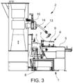
- the disclosed opening valve station 1 is defined by a supporting plane 5 of a feeding device configured for receiving a valve bag 3 or a stack of bags having the valve 4 in a closed configuration as represented.
- the supporting plane 5 may be movable/adjustable in vertical direction so that the bas to the picked up is always in flush with the valve opening device.
- the valve opening device 6 is configured for cyclically moving between a first configuration and a second configuration. In the first configuration the valve opening device 6 is able for picking up the valve bag 3 from the supporting plane 5 whereas in the second configuration the valve opening device 6 is able for opening the valve 4 and keeping the valve 4 the open configuration.
- a bag applicator device 13 in the form of a tilting arm 14.
- This tilting arm 14 is at one side connected to a linear guide 15 running along the filling stations 11 and at the opposite side is provided with a camping device 16 configured for picking up the valve bag 3 from the valve opening device 1 with the valve 4 in the open configuration.
- this clamping device is suitable for bringing the open bag, for keeping the valve open during the movement along the guide 15 and for releasing the bag at a filling station.
- the tilting arm 14 (the tilting axis is parallel to the guide 15) is in travelling configuration (i.e.
- the tilting arm 14 stops the travelling movement and starts an approaching movement (i.e. a tilting movement) towards the filling station 11 for releasing the bag 3 at a filling nozzle 12.
- the arrows TR and TI represent respectively the travelling movement along the guide 15 and the approaching/tilting movement toward and away from the filling nozzles 12.
- FIGs 5-7 disclose a valve opening device 6 according to the invention.
- this valve opening device 6 comprises a supporting frame 7 pivotally connected with respect to the supporting plane 5.
- the supporting frame 7 supports a first suction device 9 configured for coupling the bag 3 at the valve 4 and a second suction device 10 configured for coupling the opposite end of the bag 3.
- Figure 5 schematically represents the valve opening device 6 in the lower position with the second suction devices 9 and 10 acting on a closed bag 3.
- the first suction device 9 is cyclically movable (i.e. tiltable around an axis orthogonal to the guide 15) with respect to the second suction device 10 for reaching a position wherein the bag 3 is spread and the valve is open 4.
- the spread of the bag is moreover obtained by the presence of a fixed constrain 20 acting in between the two suction devices 9 10.
- the tilting movement of the frame 7 is activated so that the open valve 4 reaches a raised position.
- the bag can be picked up by the clamp 16 without requiring any approaching movement to the tilting arm from the travelling condition.
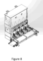
- FIGs 8 and 9 clarify what is the inline packer and the inline bag applicator within Figure 2 (figure 2 includes both the inline packer and the inline bag applicator).
- Figure 8 is a schematic view of the inline packer according to the present invention.
- Figure 9 is a schematic view of the inline bag applicator according to the present invention.
- valve bag as foregoing described and the valve opening device of the present invention may be used in other technical field, for instance for filling the bags with building materials, fertilizers and chemicals products or also food.
Landscapes
- Engineering & Computer Science (AREA)
- Mechanical Engineering (AREA)
- Supplying Of Containers To The Packaging Station (AREA)
- Supply Of Fluid Materials To The Packaging Location (AREA)
Claims (7)
- Beutelapplikatoranordnung (1) für eine stationäre Packeranordnung (2), die eine Vielzahl von Fülldüsen (12) zum Füllen von Ventilbeuteln (3) umfasst, wobei jeder der Ventilbeutel (3) ein Ventil (4) umfasst, das selektiv zwischen einer geschlossenen und einer offenen Konfiguration bewegbar ist; wobei die Beutelapplikatoranordnung (1) umfasst:- eine Beutelzuführvorrichtung (21), die eine Tragebene (5) umfasst, die zum Aufnehmen eines Ventilbeutels (3), der das Ventil (4) in der geschlossenen Konfiguration aufweist, konfiguriert ist;- eine Ventilöffnungsvorrichtung (6), die zum zyklischen Bewegen zwischen einer ersten Konfiguration, in der sie den Ventilbeutel (3) von der Tragebene (5) aufnimmt, und einer zweiten Konfiguration konfiguriert ist, wobei das Ventil (4) offen gewesen ist, und in der offenen Konfiguration gehalten wird,dadurch gekennzeichnet, dass die Ventilöffnungsvorrichtung (6) umfasst:einen Tragrahmen (7), der schwenkbar mit der Tragebene (5) verbunden ist, wobei:in einer unteren Position der Tragrahmen (7) parallel zu der Tragebene (5) ist; undin einer angehobenen Position der Tragrahmen (7) in Bezug zur Tragebene (5) gekippt ist;eine erste Saugvorrichtung (9);eine zweite Saugvorrichtung (10); undeine feste Einschränkung (20), die zwischen der ersten Saugvorrichtung (9) und der zweiten Saugvorrichtung (10) angeordnet ist, wobei:die erste Saugvorrichtung (9) und die zweite Saugvorrichtung (10) von dem Tragrahmen (7) getragen werden;die erste Saugvorrichtung (9) konfiguriert ist, um mit dem Ventilbeutel (3) an dem Ventil (4) gekoppelt zu werden;die zweite Saugvorrichtung (10) konfiguriert ist, um mit dem entgegengesetzten Ende (22) des Ventilbeutels (3) gekoppelt zu werden;die erste Saugvorrichtung (9) konfiguriert ist, um sich in Bezug zur zweite Saugvorrichtung (10) zwischen einer ersten Position, in welcher der Ventilbeutel (3) nicht aufgespreizt ist und das Ventil (4) geschlossen ist, und einer zweiten Position, in welcher der Ventilbeutel (3) aufgespreizt ist und das Ventil offen ist (4) zu bewegen, wobei das Spreizen des Ventilbeutels (3) durch die Wechselwirkung der festen Einschränkung (20) mit dem Ventilbeutel (3) ermöglicht wird; und wobei, wenn die erste Saugvorrichtung (9) die zweite Position erreicht, wenn der Ventilbeutel (3) aufgespreizt wird und das Ventil offen (4) ist, der Tragrahmen (7) angepasst ist, um sich von der unteren Position in die angehobene Position zu bewegen, sodass der Tragrahmen (7) in Bezug zur Tragebene (5) gekippt ist; und- eine Beutelapplikatorvorrichtung (13), die einen Beutelapplikatorarm umfasst, der konfiguriert ist, um:den Ventilbeutel (3) von der Ventilöffnungsvorrichtung (6) aufzunehmen, wobei der Ventilbeutel (3) von der Ventilöffnungsvorrichtung (6) aufgenommen wird, wenn sich der Tragrahmen (7) in der angehobenen Position befindet und in Bezug zur Tragebene (5) gekippt ist, den Ventilbeutel (3) in Richtung einer der Fülldüsen (12) zu bewegen, sodass jegliche Interferenz zwischen dem Ventilbeutel (3) und den Fülldüsen (12) vermieden wird;den Ventilbeutel (3) an der Fülldüse (12) freizugeben;wobei in der zweiten Konfiguration der Ventilöffnungsvorrichtung (6) die Beutelapplikatorvorrichtung (13) konfiguriert ist, um den Ventilbeutel (3) in der Fahrkonfiguration ohne zusätzliche Annäherungsbewegung aufzunehmen.
- Beutelapplikatoranordnung nach Anspruch 1, wobei die Ventilöffnungsvorrichtung (6) eine Betätigungsvorrichtung (8) umfasst, die zum zyklischen Bewegen des Tragrahmens (7) von der unteren Position in die angehobene Position und umgekehrt konfiguriert ist.
- Beutelapplikatoranordnung nach Anspruch 1, wobei der Beutelapplikatorarm (14) konfiguriert ist, um:sich selektiv entlang einer geraden Führung (15) zwischen der Ventilöffnungsvorrichtung (6) undden Fülldüsen (12) und umgekehrt zu bewegen; undin Bezug zur geraden Führung (15) zwischen der Fahrkonfiguration undeiner Freigabekonfiguration zu kippen, um den Ventilbeutel (3) an einer Fülldüse (12) freizugeben.
- Beutelapplikatoranordnung nach Anspruch 1, wobei der Beutelapplikatorarm (14) mit einer Klemmvorrichtung (16) bereitgestellt ist, die angepasst ist, um den offenen Beutel (3) an der Ventilöffnungsvorrichtung (6) aufzunehmen und den Beutel (3) in einer Füllstation (11) freizugeben.
- Beutelapplikatoranordnung nach Anspruch 1, wobei der Beutelapplikator eine Steuereinheit umfasst, die zum Steuern der Bewegung der Ventilöffnungsvorrichtung (6) von der unteren in die angehobene Position konfiguriert ist, sodass, sobald der Beutelapplikatorarm (14) die Öffnungsventilstation (1) erreicht, der Beutel (3) ohne Verzögerung durch den Beutelapplikatorarm (14) aufrecht gehalten werden kann.
- Beutelapplikatoranordnung nach Anspruch 1, wobei jede der Vielzahl von Fülldüsen (12) nebeneinander entlang einer geraden Richtung angeordnet ist, wobei jede Fülldüse (12) angepasst ist, um in der offenen Konfiguration des Ventilbeutels (3) in das Ventil (4) einzutreten und Pulvermaterial in den Beutel (3) abzugeben.
- Verfahren zum Betreiben der Beutelapplikatoranordnung nach Anspruch 1, wobei das Verfahren die Schritte umfasst, zum:a) Steuern der Ventilöffnungsvorrichtung (6) zum zyklischen Bewegen von der ersten Konfiguration in die zweite Konfiguration, um einen Ventilbeutel (3) zu öffnen und umgekehrt;b) Steuern der Beutelapplikatorvorrichtung (13) zur zyklischen Durchführung der folgenden Schritte:dadurch gekennzeichnet, dass- Aufnehmen des offenen Ventilbeutels (3) an der Öffnungsventilstation (1);- lineares Fahren von der Öffnungsventilstation (1) zu einer der Füllstationen (11) in der Fahrkonfiguration;- Annähern an die Fülldüse (12) zum Freigeben des Ventilbeutels (3);- Freigeben des Ventilbeutels (3);- Wegbewegen von der Fülldüse (12) zum Erreichen der Fahrkonfiguration;- lineares Fahren von der Füllstation (11) zu der Öffnungsventilstation (1) in der Fahrkonfiguration;
die Schritte a) und b) des Steuerns der Ventilöffnungsvorrichtung (6) und der Beutelapplikatorvorrichtung (13) ausgeführt werden, sodass, wenn die Beutelapplikatorvorrichtung (13) die Ventilöffnungsvorrichtung (6) erreicht, sich die Ventilöffnungsvorrichtung (6) in der zweiten Konfiguration befindet und der Beutel (3) ohne Verzögerung und ohne erforderliche zusätzliche Bewegung von der Beutelapplikatorvorrichtung (13) in der Bewegungskonfiguration aufgenommen werden kann.
Applications Claiming Priority (2)
| Application Number | Priority Date | Filing Date | Title |
|---|---|---|---|
| DKPA201900526 | 2019-05-01 | ||
| PCT/IB2020/054134 WO2020222185A2 (en) | 2019-05-01 | 2020-05-01 | Bag applicator assembly for a stationary packer assembly for filling valve bags, stationary packer assembly comprising this bag applicator assembly and method for operating this bag applicator assembly |
Publications (3)
| Publication Number | Publication Date |
|---|---|
| EP3962818A2 EP3962818A2 (de) | 2022-03-09 |
| EP3962818B1 true EP3962818B1 (de) | 2024-12-04 |
| EP3962818B8 EP3962818B8 (de) | 2025-01-08 |
Family
ID=70554142
Family Applications (1)
| Application Number | Title | Priority Date | Filing Date |
|---|---|---|---|
| EP20724219.9A Active EP3962818B8 (de) | 2019-05-01 | 2020-05-01 | Beutelapplikatoranordnung für eine stationäre packerbaugruppe zum füllen von ventilbeuteln und verfahren zum betrieb dieser beutelapplikatoranordnung |
Country Status (6)
| Country | Link |
|---|---|
| US (1) | US11945615B2 (de) |
| EP (1) | EP3962818B8 (de) |
| CN (1) | CN113924254B (de) |
| ES (1) | ES3001284T3 (de) |
| FI (1) | FI3962818T3 (de) |
| WO (1) | WO2020222185A2 (de) |
Family Cites Families (15)
| Publication number | Priority date | Publication date | Assignee | Title |
|---|---|---|---|---|
| US3691715A (en) * | 1970-09-28 | 1972-09-19 | St Regis Paper Co | Valve bag applicator machine |
| GB1418131A (en) * | 1972-02-19 | 1975-12-17 | Nakashima S | Automatic package bag feeding device for use with an automatic charging device |
| FR2196272B3 (de) * | 1972-08-17 | 1976-07-30 | Mahlkuch Greif Werk Ernst | |
| DE2462347C2 (de) | 1974-01-04 | 1982-12-02 | Windmöller & Hölscher, 4540 Lengerich | Vorrichtung zum automatischen Zuführen von Ventilsäcken zu einer Füllmaschine |
| IT1062787B (it) * | 1976-05-06 | 1985-01-14 | Ventomatic Italiana Srl | Macchina automatica infilasacchi su insaccatrici per materiali granulari pulvurulenti e simili |
| DE2653948C3 (de) * | 1976-11-27 | 1980-05-29 | Haver & Boecker, 4740 Oelde | Vorrichtung zum Aufstecken von leeren Ventilsäcken auf die Füllstutzen einer kontinuierlich umlaufenden Füllmaschine |
| DE2713409A1 (de) * | 1977-03-26 | 1978-09-28 | Haver & Boecker | Vorrichtung zum aufstecken von leeren ventilsaecken auf nebeneinanderliegende fuellrohre einer packmaschine |
| US4548243A (en) * | 1983-11-04 | 1985-10-22 | General Portland, Inc. | Apparatus for automatically placing bags |
| US4577454A (en) * | 1984-05-31 | 1986-03-25 | Douglas & Lomason Company | Valve bag placing machine and method |
| DE3920582A1 (de) | 1989-06-23 | 1991-01-10 | Haver & Boecker | Vorrichtung zum aufstecken von zu fuellenden ventilsaecken auf die fuellrohre einer packmaschine |
| US5050651A (en) * | 1990-07-26 | 1991-09-24 | Bates Ventil Saekke Co. A/S | Apparatus for the opening and separating of valve bags |
| DE4211089C2 (de) * | 1992-04-03 | 1997-08-07 | Haver & Boecker | Vorrichtung zur Vereinzelung von gestapelten Ventilsäcken und zum Aufstecken der Ventilsäcke auf den oder die Füllstutzen einer Ventilsackfüllmaschine |
| US7527079B2 (en) * | 2005-08-24 | 2009-05-05 | Graphic Packaging International, Inc. | Method and apparatus for facilitating filling a container |
| US20080256905A1 (en) * | 2007-04-23 | 2008-10-23 | Michael Graf | Valve bag placing system and method |
| US8272409B2 (en) | 2011-01-31 | 2012-09-25 | Target Products Ltd. | Methods, apparatus and systems for the handling of empty, flat folded storage bags in preparation for filling with a flowable material |
-
2020
- 2020-05-01 EP EP20724219.9A patent/EP3962818B8/de active Active
- 2020-05-01 US US17/607,456 patent/US11945615B2/en active Active
- 2020-05-01 FI FIEP20724219.9T patent/FI3962818T3/fi active
- 2020-05-01 WO PCT/IB2020/054134 patent/WO2020222185A2/en not_active Ceased
- 2020-05-01 ES ES20724219T patent/ES3001284T3/es active Active
- 2020-05-01 CN CN202080040700.7A patent/CN113924254B/zh active Active
Also Published As
| Publication number | Publication date |
|---|---|
| US20220219853A1 (en) | 2022-07-14 |
| EP3962818B8 (de) | 2025-01-08 |
| CN113924254A (zh) | 2022-01-11 |
| WO2020222185A2 (en) | 2020-11-05 |
| ES3001284T3 (en) | 2025-03-05 |
| FI3962818T3 (fi) | 2025-01-09 |
| US11945615B2 (en) | 2024-04-02 |
| WO2020222185A3 (en) | 2020-12-17 |
| EP3962818A2 (de) | 2022-03-09 |
| CN113924254B (zh) | 2023-05-12 |
Similar Documents
| Publication | Publication Date | Title |
|---|---|---|
| US11559962B2 (en) | Methods and machine for forming a two-piece blank assembly | |
| CA2715882C (en) | Method and device for inserting (tube) bags into cartons | |
| US3945173A (en) | Machine for automatically filling and sealing bags | |
| US4213285A (en) | Cartoning apparatus | |
| US7434376B2 (en) | Machine for packaging articles into box-like containers | |
| US12409964B2 (en) | Article bundling device, picking system and method for stacking articles and securing the stack of articles with a band | |
| US20090025343A1 (en) | Method of providing erected folding boxes at the exit of a manufacturing machine and apparatus for erecting folding boxes from flat folding box sheath | |
| KR101951347B1 (ko) | 자동 포대 공급장치 | |
| IE42059B1 (en) | Improvements relating to bag alignment in bag-handling machines | |
| US7568511B2 (en) | Synchronized stamp applicator machine and method of operating the same | |
| EP3490889B1 (de) | Maschine und verfahren zum automatischen befüllen und verschliessen von ventilsäcken | |
| EP3962818B1 (de) | Beutelapplikatoranordnung für eine stationäre packerbaugruppe zum füllen von ventilbeuteln und verfahren zum betrieb dieser beutelapplikatoranordnung | |
| KR101718151B1 (ko) | 미닫이 상자 포장의 자동포장 시스템에 있어서 속상자 자동 폴딩 공급장치 | |
| EP2392513B2 (de) | Anlage und Verfahren zum seitlichen Einwickeln von Produkten mit einer Kunststofffolie | |
| CA1080017A (en) | Cartoning apparatus | |
| US20020083684A1 (en) | Procedure and device for the accelerated filling of sacks | |
| JPS62208328A (ja) | 配積用自動整列装置 | |
| CN112693646A (zh) | 用于袋射击施加器组件的袋射击系统 | |
| EP1863711B1 (de) | Beutellader | |
| JPH11130014A (ja) | 結束機械の上押さえ装置および結束機械 | |
| JP2734736B2 (ja) | バラ物自動充填装置 | |
| US12479618B2 (en) | Packaging machine | |
| JP2673291B2 (ja) | バラ物自動充填装置 | |
| KR101969532B1 (ko) | 용기 자동포장장치 | |
| EP3119681B1 (de) | System zur positionierung eines etikeiits auf einer verpackung |
Legal Events
| Date | Code | Title | Description |
|---|---|---|---|
| STAA | Information on the status of an ep patent application or granted ep patent |
Free format text: STATUS: UNKNOWN |
|
| STAA | Information on the status of an ep patent application or granted ep patent |
Free format text: STATUS: THE INTERNATIONAL PUBLICATION HAS BEEN MADE |
|
| PUAI | Public reference made under article 153(3) epc to a published international application that has entered the european phase |
Free format text: ORIGINAL CODE: 0009012 |
|
| STAA | Information on the status of an ep patent application or granted ep patent |
Free format text: STATUS: REQUEST FOR EXAMINATION WAS MADE |
|
| 17P | Request for examination filed |
Effective date: 20211029 |
|
| AK | Designated contracting states |
Kind code of ref document: A2 Designated state(s): AL AT BE BG CH CY CZ DE DK EE ES FI FR GB GR HR HU IE IS IT LI LT LU LV MC MK MT NL NO PL PT RO RS SE SI SK SM TR |
|
| DAV | Request for validation of the european patent (deleted) | ||
| DAX | Request for extension of the european patent (deleted) | ||
| STAA | Information on the status of an ep patent application or granted ep patent |
Free format text: STATUS: EXAMINATION IS IN PROGRESS |
|
| 17Q | First examination report despatched |
Effective date: 20230808 |
|
| GRAP | Despatch of communication of intention to grant a patent |
Free format text: ORIGINAL CODE: EPIDOSNIGR1 |
|
| STAA | Information on the status of an ep patent application or granted ep patent |
Free format text: STATUS: GRANT OF PATENT IS INTENDED |
|
| INTG | Intention to grant announced |
Effective date: 20240904 |
|
| GRAS | Grant fee paid |
Free format text: ORIGINAL CODE: EPIDOSNIGR3 |
|
| GRAA | (expected) grant |
Free format text: ORIGINAL CODE: 0009210 |
|
| STAA | Information on the status of an ep patent application or granted ep patent |
Free format text: STATUS: THE PATENT HAS BEEN GRANTED |
|
| REG | Reference to a national code |
Ref country code: DE Ref legal event code: R081 Ref document number: 602020042465 Country of ref document: DE Owner name: FLSMIDTH CEMENT A/S, DK Free format text: FORMER OWNER: FLSMIDTH A/S, VALBY, DK |
|
| AK | Designated contracting states |
Kind code of ref document: B1 Designated state(s): AL AT BE BG CH CY CZ DE DK EE ES FI FR GB GR HR HU IE IS IT LI LT LU LV MC MK MT NL NO PL PT RO RS SE SI SK SM TR |
|
| RAP2 | Party data changed (patent owner data changed or rights of a patent transferred) |
Owner name: FLSMIDTH CEMENT A/S |
|
| REG | Reference to a national code |
Ref country code: CH Ref legal event code: PK Free format text: BERICHTIGUNG B8 Ref country code: CH Ref legal event code: EP |
|
| REG | Reference to a national code |
Ref country code: DE Ref legal event code: R096 Ref document number: 602020042465 Country of ref document: DE |
|
| REG | Reference to a national code |
Ref country code: IE Ref legal event code: FG4D |
|
| REG | Reference to a national code |
Ref country code: FI Ref legal event code: FGE |
|
| REG | Reference to a national code |
Ref country code: LT Ref legal event code: MG9D |
|
| REG | Reference to a national code |
Ref country code: NL Ref legal event code: MP Effective date: 20241204 |
|
| PG25 | Lapsed in a contracting state [announced via postgrant information from national office to epo] |
Ref country code: HR Free format text: LAPSE BECAUSE OF FAILURE TO SUBMIT A TRANSLATION OF THE DESCRIPTION OR TO PAY THE FEE WITHIN THE PRESCRIBED TIME-LIMIT Effective date: 20241204 |
|
| PG25 | Lapsed in a contracting state [announced via postgrant information from national office to epo] |
Ref country code: BG Free format text: LAPSE BECAUSE OF FAILURE TO SUBMIT A TRANSLATION OF THE DESCRIPTION OR TO PAY THE FEE WITHIN THE PRESCRIBED TIME-LIMIT Effective date: 20241204 |
|
| PG25 | Lapsed in a contracting state [announced via postgrant information from national office to epo] |
Ref country code: NO Free format text: LAPSE BECAUSE OF FAILURE TO SUBMIT A TRANSLATION OF THE DESCRIPTION OR TO PAY THE FEE WITHIN THE PRESCRIBED TIME-LIMIT Effective date: 20250304 |
|
| PG25 | Lapsed in a contracting state [announced via postgrant information from national office to epo] |
Ref country code: LV Free format text: LAPSE BECAUSE OF FAILURE TO SUBMIT A TRANSLATION OF THE DESCRIPTION OR TO PAY THE FEE WITHIN THE PRESCRIBED TIME-LIMIT Effective date: 20241204 Ref country code: GR Free format text: LAPSE BECAUSE OF FAILURE TO SUBMIT A TRANSLATION OF THE DESCRIPTION OR TO PAY THE FEE WITHIN THE PRESCRIBED TIME-LIMIT Effective date: 20250305 |
|
| PG25 | Lapsed in a contracting state [announced via postgrant information from national office to epo] |
Ref country code: RS Free format text: LAPSE BECAUSE OF FAILURE TO SUBMIT A TRANSLATION OF THE DESCRIPTION OR TO PAY THE FEE WITHIN THE PRESCRIBED TIME-LIMIT Effective date: 20250304 |
|
| PG25 | Lapsed in a contracting state [announced via postgrant information from national office to epo] |
Ref country code: NL Free format text: LAPSE BECAUSE OF FAILURE TO SUBMIT A TRANSLATION OF THE DESCRIPTION OR TO PAY THE FEE WITHIN THE PRESCRIBED TIME-LIMIT Effective date: 20241204 |
|
| REG | Reference to a national code |
Ref country code: AT Ref legal event code: MK05 Ref document number: 1747952 Country of ref document: AT Kind code of ref document: T Effective date: 20241204 |
|
| P01 | Opt-out of the competence of the unified patent court (upc) registered |
Free format text: CASE NUMBER: APP_23303/2025 Effective date: 20250515 |
|
| PG25 | Lapsed in a contracting state [announced via postgrant information from national office to epo] |
Ref country code: SM Free format text: LAPSE BECAUSE OF FAILURE TO SUBMIT A TRANSLATION OF THE DESCRIPTION OR TO PAY THE FEE WITHIN THE PRESCRIBED TIME-LIMIT Effective date: 20241204 |
|
| PGFP | Annual fee paid to national office [announced via postgrant information from national office to epo] |
Ref country code: FI Payment date: 20250526 Year of fee payment: 6 |
|
| PG25 | Lapsed in a contracting state [announced via postgrant information from national office to epo] |
Ref country code: PL Free format text: LAPSE BECAUSE OF FAILURE TO SUBMIT A TRANSLATION OF THE DESCRIPTION OR TO PAY THE FEE WITHIN THE PRESCRIBED TIME-LIMIT Effective date: 20241204 |
|
| PGFP | Annual fee paid to national office [announced via postgrant information from national office to epo] |
Ref country code: DE Payment date: 20250528 Year of fee payment: 6 |
|
| PGFP | Annual fee paid to national office [announced via postgrant information from national office to epo] |
Ref country code: ES Payment date: 20250612 Year of fee payment: 6 |
|
| PG25 | Lapsed in a contracting state [announced via postgrant information from national office to epo] |
Ref country code: IS Free format text: LAPSE BECAUSE OF FAILURE TO SUBMIT A TRANSLATION OF THE DESCRIPTION OR TO PAY THE FEE WITHIN THE PRESCRIBED TIME-LIMIT Effective date: 20250404 |
|
| PGFP | Annual fee paid to national office [announced via postgrant information from national office to epo] |
Ref country code: IT Payment date: 20250522 Year of fee payment: 6 |
|
| PG25 | Lapsed in a contracting state [announced via postgrant information from national office to epo] |
Ref country code: PT Free format text: LAPSE BECAUSE OF FAILURE TO SUBMIT A TRANSLATION OF THE DESCRIPTION OR TO PAY THE FEE WITHIN THE PRESCRIBED TIME-LIMIT Effective date: 20250404 |
|
| PG25 | Lapsed in a contracting state [announced via postgrant information from national office to epo] |
Ref country code: AT Free format text: LAPSE BECAUSE OF FAILURE TO SUBMIT A TRANSLATION OF THE DESCRIPTION OR TO PAY THE FEE WITHIN THE PRESCRIBED TIME-LIMIT Effective date: 20241204 Ref country code: RO Free format text: LAPSE BECAUSE OF FAILURE TO SUBMIT A TRANSLATION OF THE DESCRIPTION OR TO PAY THE FEE WITHIN THE PRESCRIBED TIME-LIMIT Effective date: 20241204 |
|
| PG25 | Lapsed in a contracting state [announced via postgrant information from national office to epo] |
Ref country code: SK Free format text: LAPSE BECAUSE OF FAILURE TO SUBMIT A TRANSLATION OF THE DESCRIPTION OR TO PAY THE FEE WITHIN THE PRESCRIBED TIME-LIMIT Effective date: 20241204 |
|
| PGFP | Annual fee paid to national office [announced via postgrant information from national office to epo] |
Ref country code: TR Payment date: 20250411 Year of fee payment: 6 |
|
| PG25 | Lapsed in a contracting state [announced via postgrant information from national office to epo] |
Ref country code: CZ Free format text: LAPSE BECAUSE OF FAILURE TO SUBMIT A TRANSLATION OF THE DESCRIPTION OR TO PAY THE FEE WITHIN THE PRESCRIBED TIME-LIMIT Effective date: 20241204 |
|
| REG | Reference to a national code |
Ref country code: DE Ref legal event code: R097 Ref document number: 602020042465 Country of ref document: DE |
|
| PG25 | Lapsed in a contracting state [announced via postgrant information from national office to epo] |
Ref country code: SE Free format text: LAPSE BECAUSE OF FAILURE TO SUBMIT A TRANSLATION OF THE DESCRIPTION OR TO PAY THE FEE WITHIN THE PRESCRIBED TIME-LIMIT Effective date: 20241204 |
|
| PG25 | Lapsed in a contracting state [announced via postgrant information from national office to epo] |
Ref country code: DK Free format text: LAPSE BECAUSE OF FAILURE TO SUBMIT A TRANSLATION OF THE DESCRIPTION OR TO PAY THE FEE WITHIN THE PRESCRIBED TIME-LIMIT Effective date: 20241204 |
|
| PLBE | No opposition filed within time limit |
Free format text: ORIGINAL CODE: 0009261 |
|
| STAA | Information on the status of an ep patent application or granted ep patent |
Free format text: STATUS: NO OPPOSITION FILED WITHIN TIME LIMIT |
|
| REG | Reference to a national code |
Ref country code: CH Ref legal event code: L10 Free format text: ST27 STATUS EVENT CODE: U-0-0-L10-L00 (AS PROVIDED BY THE NATIONAL OFFICE) Effective date: 20251015 |
|
| 26N | No opposition filed |
Effective date: 20250905 |
|
| REG | Reference to a national code |
Ref country code: CH Ref legal event code: H13 Free format text: ST27 STATUS EVENT CODE: U-0-0-H10-H13 (AS PROVIDED BY THE NATIONAL OFFICE) Effective date: 20251223 |
|
| PG25 | Lapsed in a contracting state [announced via postgrant information from national office to epo] |
Ref country code: LU Free format text: LAPSE BECAUSE OF NON-PAYMENT OF DUE FEES Effective date: 20250501 |
|
| PG25 | Lapsed in a contracting state [announced via postgrant information from national office to epo] |
Ref country code: CH Free format text: LAPSE BECAUSE OF NON-PAYMENT OF DUE FEES Effective date: 20250531 |
|
| GBPC | Gb: european patent ceased through non-payment of renewal fee |
Effective date: 20250501 |
|
| REG | Reference to a national code |
Ref country code: BE Ref legal event code: MM Effective date: 20250531 |
|
| PG25 | Lapsed in a contracting state [announced via postgrant information from national office to epo] |
Ref country code: MC Free format text: LAPSE BECAUSE OF FAILURE TO SUBMIT A TRANSLATION OF THE DESCRIPTION OR TO PAY THE FEE WITHIN THE PRESCRIBED TIME-LIMIT Effective date: 20241204 |
|
| PG25 | Lapsed in a contracting state [announced via postgrant information from national office to epo] |
Ref country code: GB Free format text: LAPSE BECAUSE OF NON-PAYMENT OF DUE FEES Effective date: 20250501 |
|
| PG25 | Lapsed in a contracting state [announced via postgrant information from national office to epo] |
Ref country code: IE Free format text: LAPSE BECAUSE OF NON-PAYMENT OF DUE FEES Effective date: 20250501 |
|
| PG25 | Lapsed in a contracting state [announced via postgrant information from national office to epo] |
Ref country code: BE Free format text: LAPSE BECAUSE OF NON-PAYMENT OF DUE FEES Effective date: 20250531 |
|
| PG25 | Lapsed in a contracting state [announced via postgrant information from national office to epo] |
Ref country code: FR Free format text: LAPSE BECAUSE OF NON-PAYMENT OF DUE FEES Effective date: 20250531 |