EP3961908B1 - Dispositif servo-amplificateur et dispositif de servocommande multiaxial - Google Patents
Dispositif servo-amplificateur et dispositif de servocommande multiaxial Download PDFInfo
- Publication number
- EP3961908B1 EP3961908B1 EP20795084.1A EP20795084A EP3961908B1 EP 3961908 B1 EP3961908 B1 EP 3961908B1 EP 20795084 A EP20795084 A EP 20795084A EP 3961908 B1 EP3961908 B1 EP 3961908B1
- Authority
- EP
- European Patent Office
- Prior art keywords
- power supply
- servo amplifier
- housing
- servo
- disposed
- Prior art date
- Legal status (The legal status is an assumption and is not a legal conclusion. Google has not performed a legal analysis and makes no representation as to the accuracy of the status listed.)
- Active
Links
Images


Classifications
-
- H—ELECTRICITY
- H02—GENERATION; CONVERSION OR DISTRIBUTION OF ELECTRIC POWER
- H02P—CONTROL OR REGULATION OF ELECTRIC MOTORS, ELECTRIC GENERATORS OR DYNAMO-ELECTRIC CONVERTERS; CONTROLLING TRANSFORMERS, REACTORS OR CHOKE COILS
- H02P5/00—Arrangements specially adapted for regulating or controlling the speed or torque of two or more electric motors
- H02P5/74—Arrangements specially adapted for regulating or controlling the speed or torque of two or more electric motors controlling two or more AC dynamo-electric motors
-
- H—ELECTRICITY
- H05—ELECTRIC TECHNIQUES NOT OTHERWISE PROVIDED FOR
- H05K—PRINTED CIRCUITS; CASINGS OR CONSTRUCTIONAL DETAILS OF ELECTRIC APPARATUS; MANUFACTURE OF ASSEMBLAGES OF ELECTRICAL COMPONENTS
- H05K7/00—Constructional details common to different types of electric apparatus
- H05K7/14—Mounting supporting structure in casing or on frame or rack
- H05K7/1462—Mounting supporting structure in casing or on frame or rack for programmable logic controllers [PLC] for automation or industrial process control
- H05K7/1465—Modular PLC assemblies with separable functional units
-
- H—ELECTRICITY
- H05—ELECTRIC TECHNIQUES NOT OTHERWISE PROVIDED FOR
- H05K—PRINTED CIRCUITS; CASINGS OR CONSTRUCTIONAL DETAILS OF ELECTRIC APPARATUS; MANUFACTURE OF ASSEMBLAGES OF ELECTRICAL COMPONENTS
- H05K7/00—Constructional details common to different types of electric apparatus
- H05K7/14—Mounting supporting structure in casing or on frame or rack
- H05K7/1462—Mounting supporting structure in casing or on frame or rack for programmable logic controllers [PLC] for automation or industrial process control
- H05K7/1468—Mechanical features of input/output (I/O) modules
- H05K7/1471—Modules for controlling actuators
Definitions
- the present invention relates to a servo amplifier device that controls and drives a servo motor, and a multiaxis servo control device that includes a plurality of the servo amplifier devices and that control and drive a plurality of the servo motors.
- a processing machine having an arm configured with a plurality of axes.
- a plurality of servo amplifier devices (hereinafter, simply referred to as servo amplifiers, as appropriate) each for controlling and driving a servo motor are also demanded in accordance with a number of axes.
- a servo amplifier group occupies a larger space.
- wiring connected with the servo motors, wiring for servo amplifier control, and the like also increase. For this reason, a wiring process becomes complicated, and a connection error or the like easily occurs. Therefore, a multiaxis servo drive device having the purpose for, for example, improving work efficiency by simplifying the wiring has been conventionally proposed (see, for example, PTL 1).
- Such a conventional multiaxis servo drive device includes a converter unit that outputs DC power, and a plurality of servo amplifier units, each of which drives a servo motor.
- Each of the units includes a connector for wiring that enables a cable connection for, for example, a DC power supply or a motor power line.
- the conventional multiaxis servo drive device includes a mount base including a circuit board. On such a circuit board, a receiving-side connector corresponding to a connector of each unit is disposed, and the wiring process is also performed beforehand.
- the conventional multiaxis servo drive device is configured by disposing each connector of each unit so as to be fitted and connected with the receiving-side connector of the mount base.
- PTL 1 Unexamined Japanese Patent Publication No. 2005-261120 US 5,493,194 A discloses a motor control system and an electrical bus for interconnecting the components of the control system.
- the system includes a main motor control unit connected to four motor axis control modules.
- the control algorithms and commands for the system are stored and executed by the control unit which communicates control commands to the individual motor axis control modules.
- Each motor control module processes the control commands to control a motor connected to the module, and also communicates feedback signals produced at the associated axis to the control unit.
- the interconnection between the control unit and the modules is positioned at the face of the components to facilitate removal and insertion of the modules.
- the electrical bus includes both communications conductors and power conductors, and is included in the interconnection of the components.
- JP 2014 183711 A discloses a motor driving apparatus including at least one motor driving unit, the motor driving unit includes a drive circuit substrate on which a drive circuit and a control circuit of a motor are mounted and a frame on which the drive circuit substrate is fixed.
- a power supply circuit substrate on which a power supply circuit for supplying power to the drive circuit substrate is to be mounted and a cover member for covering the power supply circuit substrate can be attached to the X2 direction side of the frame, and in a state where the power supply circuit substrate and the cover member are detached from the frame of a motor driving unit, an X2 direction end of the frame of the motor driving unit can be brought into contact with an X1 direction end of the frame of a motor driving unit.
- CN 106 602 968 A discloses a high-power servo motor driving field and especially a servo motor driving unit structure.
- the servo motor driving unit structure has a special structure.
- the structure can be used for servo motor driving control, and is formed by function modules and a special housing structure.
- the housing is a book-type cuboid structure.
- the top surface and bottom surface of the housing structure are provided with a DC bus duct body, an mBUS interface, an MC_GPIO interface, a speed sensor interface, an MC_CNRLA interface and a motor interface, which are arranged corresponding to the corresponding function modules respectively, thereby realizing corresponding driving control functions and enabling the overall size to be smaller; besides, the overall structure is in a book shape, which facilitates modular production and joint integrated installation with other related unit modules; and the servo motor driving unit structure is of great significance to occasions (such as on a highspeed rail), where installation space is limited.
- the present servo amplifier device has only to be attached on the back surface side.
- this configuration eliminates the need for a dedicated installation member such as a rack structure.
- the housing can be easily attached to a wall or an inexpensive plate-shaped installation member by using the attachment portion.
- a number of servo amplifier devices is no longer limited.
- the connector or the connection portion is configured to be distributed to the respective surfaces of the housing according to the function. Therefore, the work efficiency together with the ease of the wiring can be improved.
- the DC power supply connection unit is preferably disposed to be closer to a center side than the display unit is on the front surface of the housing.
- the display unit is preferably disposed to be closer to the communication connector than the motor driving connector on the front surface of the housing.
- a multiaxis servo control device is a multiaxis servo control device including a plurality of the above-described servo amplifier devices and configured to control and drive a plurality of the motors.
- the present multiaxis servo control device includes a power supply device including a DC power supply output unit that outputs the DC power, and configured to supply the DC power from the DC power supply output unit to each of the servo amplifier devices; an installation board that is the installation member for attaching the power supply device and the plurality of servo amplifier devices; and the DC power supply line that connects the DC power supply connection unit of each of the servo amplifier devices.
- the plurality of servo amplifier devices are arranged side by side in a normal direction with respect to the first surfaces, and are each attached to the installation board via the attachment portion provided on the back surface side of the housing.
- each servo amplifier device has only to be fixed to an installation member having a simple configuration such as the installation board. Therefore, an additional installation of the servo amplifier device or a change in the arrangement configuration of the servo amplifier devices on the installation board can be easily achieved.
- the connectors or the connection portions are distributed according to the function to be disposed on the respective surfaces of the housing. Therefore, the wiring process can also be performed for each function by using a space above or a space below the servo amplifier devices arranged side by side in the lateral direction. Therefore, the wiring becomes easy, and a work error or the like can be suppressed.
- a plurality of split bus bars each including a metal plate as the DC power supply line is further included, and the DC power supply connection units included in the servo amplifier devices adjacent to each other are connected through the split bus bar.
- the power supply device includes: a power supply housing that houses a power supply circuit to be supplied with a commercial power supply to generate DC power; a power supply attachment portion for attaching the power supply housing to the installation board; and a DC power supply output unit that outputs the DC power.
- the power supply housing has a box shape having a pair of first surfaces facing each other and each having a largest area, a commercial power supply input line supplied with the commercial power supply is disposed on a pair of second surfaces perpendicular to the first surfaces and facing each other, on a pair of third surfaces perpendicular to the first surfaces and the second surfaces and facing each other, the power supply attachment portion is disposed on a back surface side with one of the third surfaces being as a back surface, and the DC power supply output unit is disposed on a front surface with the other one of the third surfaces being as the front surface.
- the power supply device and the plurality of servo amplifier devices are disposed side by side in a normal direction with respect to the first surfaces of the housings of the servo amplifier devices, and are each attached to the installation board via the attachment portion provided on the back surface side of the housing of the servo amplifier device.
- a multiaxis servo control device that conducts servo control on a plurality of servo motors constituting multiple axes can be achieved with a simple configuration.
- FIG. 1 is a configuration diagram of servo system 200 including multiaxis servo control device 100 provided with a plurality of servo amplifier devices 10 according to an exemplary embodiment of the present invention.
- servo system 200 includes multiaxis servo control device 100, a plurality of servo motors (hereinafter, simply referred to as motors, as appropriate) 80 to be controlled and driven by multiaxis servo control device 100, and host controller 71 that controls each servo amplifier device 10.
- FIG. 1 illustrates a configuration example of three-axis servo system 200, in which three pairs of servo amplifier devices 10 and motors 80 are provided with one servo amplifier device 10 and one motor 80 constituting one pair.
- Multiaxis servo control device 100 in servo system 200 includes three servo amplifier devices 10, power supply device 50 that supplies DC power to each servo amplifier device 10, and installation board 60 on which each servo amplifier device 10 and power supply device 50 are installed.
- a brushless motor is suitable in addition to the servo motor. That is, as a configuration example of motor 80, as illustrated by using one of motors 80 in FIG. 1 , a brushless motor can be mentioned.
- stator 83 fixed to motor housing 81, rotor 84 disposed on an inner circumferential side of stator 83, and bearing 85 that supports rotor 84 are housed in motor housing 81.
- stator 83 is formed by winding three-phase windings of a U phase, a V phase, and a W phase around a stator core.
- the drive voltage for the rotation control as described above is supplied from servo amplifier device 10 to motor 80 via drive line 87.
- Motor 80 includes encoder 86 for detecting the rotational position of rotor 84.
- a signal from encoder 86 is supplied to servo amplifier device 10 via encoder line 88.
- the present exemplary embodiment is characterized in that the power is supplied by using a so-called bus bar in order to constitute a DC power supply line for supplying the DC power in this manner.
- the bus bar is a member used to conduct an electric current of a large capacity, and its conductive portion is configured with a conductor plate or a conductor rod formed of a metal such as copper or aluminum.
- a power supply connection is accomplished by using split bus bars 55 that respectively connect devices to straddle the devices like jumper wires at the central parts on the front surfaces of power supply device 50 and each servo amplifier device 10. Note that the power supply connection using split bus bars 55 will be described later in more detail.
- Each servo amplifier device 10 is connected with host controller 71 in order to control the control drive circuit incorporated in each servo amplifier device 10.
- host controller 71 and each servo amplifier device 10 communicate with each other via communication line 72.
- communication line 72 Note that, in the present exemplary embodiment, an example of wired communication using communication line 72 has been described. However, wireless communication may be configured.
- host controller 71 for example, a personal computer can be used in a case of parameter settings or the like, and a programmable logic controller (PLC) or a motion controller can be used in a case of giving an action command for instructing the rotation position, the speed, or the like.
- PLC programmable logic controller
- a motion controller can be used in a case of giving an action command for instructing the rotation position, the speed, or the like.
- PLC programmable logic controller
- PLC programmable logic controller
- motion controller can be used in a case of giving an action command for instructing the rotation position, the speed, or the like.
- PLC programmable logic controller
- PLC programmable logic controller
- motion controller can be used in a case of giving an action command for instructing the rotation position, the speed, or the like.
- RTEX realtime express
- EtherCAT registered trademark
- host controller 71 sends various types of information including an action command to each servo amplifier device 10, and also receives various types of information from each servo amplifier device 10, such that motor 80 conducts a desired action. For example, in a case where servo amplifier device 10 controls the position of rotor 84 included in motor 80, host controller 71 notifies of a target position command, and in a case where the speed of rotor 84 is controlled, host controller 71 notifies of a target speed command.
- servo amplifier device 10 controls and drives the motion and action of motor 80, based on the action command from host controller 71. Therefore, servo amplifier device 10 includes a controller and a drive unit each being as a main circuit configuration.
- the main operation of the controller includes functions of feedback control as follows. That is, the controller is supplied with a command signal indicating an action command from host controller 71 as described above via communication line 72, and a detection signal indicating the position or speed that has been detected by encoder 86 from encoder 86 of motor 80 via encoder line 88.
- the controller generates a control signal using such a command signal and such a detection signal, based on, for example, the feedback control, and controls the action of motor 80 such that the motion position or the speed of motor 80 follows the action command.
- the controller is preferably, for example, the central processing unit (CPU) or a microcomputer incorporating a memory in which a program is stored.
- the drive unit includes a so-called inverter.
- the inverter is configured with power conversion elements such as a switching element and a diode.
- the inverter uses these elements to generate a drive voltage having a drive waveform corresponding to the control signal.
- This drive voltage is supplied to the windings of motor 80 via drive line 87. Accordingly, the windings of motor 80 are energized, and rotor 84 and rotation shaft 82 in motor 80 rotate.
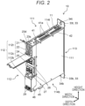
- FIG. 2 is an external view of servo amplifier device 10 according to the exemplary embodiment of the present invention.
- servo amplifier device 10 has a thin box shape in outer appearance. That is, amplifier housing 11 having a rectangular parallelepiped shape with a pair of first surfaces, a pair of second surfaces, and a pair of third surfaces forms a foundation part in the outer appearance of servo amplifier device 10.
- the pair of first surfaces are side surfaces 111 each having the largest area.
- the pair of second surfaces perpendicular to side surfaces 111, which are the first surfaces are upper surface 114t and lower surface 114b.
- the pair of third surfaces perpendicular to the first surfaces and the second surfaces are front surface 112 and back surface 113.
- a direction in which the pair of side surfaces 111 face each other will be described as a width direction
- a direction in which upper surface 114t and lower surface 114b face each other will be described as a height direction
- a direction in which front surface 112 and back surface 113 face each other will be described as a depth direction.
- a side of upper surface 114t will be described as an upper side
- a side of lower surface 114b will be described as a lower side.
- a side of front surface 112 will be described as a front side
- a side of back surface 113 will be described as a back side. Therefore, as illustrated in FIG. 2 , servo amplifier device 10 has a box shape in which the height direction and the depth direction are almost the same in the length, and the width direction is thinner than the height direction and the depth direction.
- each servo amplifier device 10 As illustrated in FIG. 1 , as a basic configuration of multiaxis servo control device 100, power supply device 50 and each servo amplifier device 10 are arranged in the width direction perpendicular to side surfaces 111 of each servo amplifier device 10. In other words, three servo amplifier devices 10 are arranged side by side in the normal direction with respect to side surfaces 111, which are the first surfaces. Therefore, as illustrated in FIG. 2 , in servo amplifier device 10, on both side surfaces 111, basically, no member is configured to be disposed except for a fixing member such as a bolt for fixing a side plate. Both side surfaces 111 are flat surfaces without a protrusion.
- back surfaces 113 of servo amplifier devices 10 are basically fixed. Therefore, attachment portion 33 for fixing servo amplifier device 10 itself to installation board 60 is provided on a side of back surface 113.
- installation board 60 is configured with base portion 61 that serves as a base when servo amplifier device 10 is disposed at an installation place, and attachment plate 62 that extends in the height direction from base portion 61 and spreads in a plate shape.
- no member is configured to be disposed on the surface of back surface 113 in a similar manner to side surfaces 111. As illustrated in FIG.
- attachment portion 33 includes, on the side of back surface 113, upper attachment portion 33t having a small area of a plate shape and extending upward in the height direction from the surface of back surface 113 of amplifier housing 11, and lower attachment portion 33b having a plate shape and extending downward in the height direction.
- Upper attachment portion 33t and lower attachment portion 33b respectively have attachment holes 34t, 34b to fix servo amplifier device 10 itself to installation board 60 using a fixing member such as a bolt or a screw.
- a fixing member such as a bolt or a screw.
- one servo amplifier device 10 is fixed to installation board 60.
- bolt 35t is screwed through attachment hole 34t
- bolt 35b is screwed through attachment hole 34b into attachment plate 62, so as to fix servo amplifier device 10 itself to installation board 60.
- attachment plate 62 screw holes are formed beforehand at positions corresponding to respective positions of attachment holes 34t, 34b, so that the work of attaching and detaching servo amplifier device 10 to and from installation board 60 is facilitated. Further, by forming a plurality of such screw holes in the lateral direction (the width direction) of attachment plate 62, an additional installation of servo amplifier device 10 is facilitated.
- I/O connector 41a is used, for example, for inputting or outputting an input signal from each type of switch or sensor or an output signal or the like for driving a relay or the like, which is mounted on a processing machine controlled by the multiaxis servo control device. Furthermore, as illustrated in FIG. 2 , heat radiation holes 42 for heat radiation and the like are formed on upper surface 114t of amplifier housing 11.
- motor driving connector 45 and encoder connector 46 are disposed on lower surface 114b of amplifier housing 11.
- Motor driving connector 45 is a connector for connecting drive line 87.
- a drive voltage is supplied from servo amplifier device 10 to motor 80 via motor driving connector 45 and drive line 87.
- Encoder connector 46 is a connector for connecting encoder line 88.
- a detection signal indicating a detection position and the like is supplied from motor 80 to servo amplifier device 10 via encoder line 88 and encoder connector 46.
- the connectors for making connections are disposed separately on the side of upper surface 114t and on the side of lower surface 114b of servo amplifier device 10 depending on the function. Therefore, as can be understood from FIG. 1 , an empty space on the side of upper surface 114t is available for each servo amplifier device 10 installed on installation board 60 for wiring of a connection with host controller 71, such as communication line 72. An empty space on the side of lower surface 114b is available for wiring of a connection between drive line 87, encoder line 88, or the like and motor 80.
- FIG. 3 is a front view illustrating front surface 112 of servo amplifier device 10.
- a configuration of front surface 112 constituting amplifier housing 11 of servo amplifier device 10 will be described with reference to FIGS. 1 , 2 , and 3 .
- front surface 112 of amplifier housing 11 is divided into front surface upper portion 112t, front surface middle portion 112c, and front surface lower portion 112b from upper surface 114t to lower surface 114b in the height direction.
- a display unit for displaying information simply with a display member, and a DC power supply connection unit for connecting a DC power supply are disposed on front surface 112.
- Front surface upper portion 112t serves as an interface area including the display unit.
- Front surface middle portion 112c which is closer to the center than the display unit is, serves as an area for power supply distribution that is the DC power supply connection unit.
- Front surface lower portion 112b In front surface lower portion 112b, at its lower part, ground terminal 29 for connecting to the ground is provided. Front surface lower portion 112b has a flat shape except for ground terminal 29.
- FIGS. 1 to 3 illustrate an example in which two seven-segment displays 23d are disposed.
- Front surface upper portion 112t includes upper door 21, which is transparent and is a vertically openable door.
- the main body side in the depth direction with respect to upper door 21, which is closed, is defined as member arrangement portion 22, in which a member for a simple interface and the like are arranged.
- member arrangement portion 22 a member for device address setting including seven-segment displays 23d and a member for a simple operation by a user are arranged.
- Upper door 21 is a door that is made of a resin and that is openable and closable in a vertically openable manner. Upper door 21 is openable and closable to rotate vertically around the vicinity of upper surface 114t, when viewed from the lateral direction.
- front surface middle portion 112c serves as DC power supply connection unit 25 to be described next. That is, a bus bar connector configured to connect the metal plate of split bus bar 55 is disposed in DC power supply connection unit 25. More specifically, split bus bar 55 is configured to be an insertion plug type.
- socket portions 26, into or from which split bus bars 55 are respectively insertable and removable are provided in the main body of servo amplifier device 10. By inserting split bus bar 55 into socket portion 26, an electrical connection is established.
- front surface middle portion 112c also includes middle door 24, which is a vertically openable door.
- the main body side in the depth direction with respect to middle door 24, which is closed, is defined as DC power supply connection unit 25.
- Socket portions 26 are disposed in DC power supply connection unit 25.
- Middle door 24 is also an openable and closable door in a vertically openable manner, and is openable and closable to rotate vertically around the vicinity the upper side of front surface middle portion 112c, when viewed from the lateral direction.
Landscapes
- Engineering & Computer Science (AREA)
- Automation & Control Theory (AREA)
- Microelectronics & Electronic Packaging (AREA)
- Power Engineering (AREA)
- Control Of Multiple Motors (AREA)
- Control Of Ac Motors In General (AREA)
Claims (9)
- Dispositif servo-amplificateur (10) qui incorpore un circuit d'entraînement de commande configuré pour commander et entraîner un moteur (80), le dispositif servo-amplificateur (10) comprenant:un boîtier qui loge le circuit d'entraînement de commande;une portion de fixation (33) pour fixer le boîtier à un élément d'installation ;une unité de connexion d'alimentation CC (25) connectée à une ligne d'alimentation CC afin de recevoir de la puissance CC ;un connecteur de communication (41) connecté à un dispositif de commande externe afin de recevoir un signal de communication ;un connecteur d'entraînement de moteur (45) connecté à une ligne d'entraînement (87) pour entraîner le moteur (80) ; etune unité d'affichage disposée avec un élément d'affichage, dans lequelle boîtier présente une forme de boîte ayant une paire de premières surfaces (111) se faisant face et ayant chacune une aire la plus grande,le connecteur de communication (41) et le connecteur d'entraînement de moteur (45) sont disposés sur une paire de deuxièmes surfaces (114b, 114t) perpendiculaires aux premières surfaces (111) et se faisant face,sur une paire de troisièmes surfaces (112, 113) perpendiculaires aux premières surfaces (111) et aux deuxièmes surfaces (114b, 114t) et se faisant face, la portion de fixation (33) est disposée sur un côté surface arrière (113), l'une des troisièmes surfaces (112, 113) servant de surface arrière (113), etl'unité d'affichage et l'unité de connexion d'alimentation CC (25) sont disposées sur une surface avant (112), une autre des troisièmes surfaces (112, 113) étant la surface avant (112).
- Dispositif servo-amplificateur (10) selon la revendication 1, dans lequella ligne d'alimentation CC est une barre omnibus incluant une plaque en métal, etl'unité de connexion d'alimentation CC (25) est un connecteur de barre omnibus configuré pour connecter la plaque en métal de la barre omnibus.
- Dispositif servo-amplificateur (10) selon la revendication 1, dans lequel l'unité de connexion d'alimentation CC (25) est disposée de sorte à être plus proche d'un côté central que l'unité d'affichage ne l'est sur la surface avant (112) du boîtier.
- Dispositif servo-amplificateur (10) selon la revendication 1, dans lequel le connecteur de communication (41) est disposé sur l'une de la paire de deuxièmes surfaces (114b, 114t), et le connecteur d'entraînement de moteur (45) est disposé sur une autre de la paire de deuxièmes surfaces (114b, 114t).
- Dispositif servo-amplificateur (10) selon la revendication 1, dans lequel l'unité d'affichage est disposée de sorte à être plus proche du connecteur de communication (41) que le connecteur d'entraînement de moteur (45) sur la surface avant du boîtier.
- Dispositif de servocommande multiaxial (100) comprenant une pluralité des dispositifs servo-amplificateurs (10) selon l'une quelconque des revendications 1 à 5, et configuré pour commander et entraîner une pluralité des moteurs (80), le dispositif de servocommande multiaxial (100) comprenant :un dispositif d'alimentation (50) incluant une unité de sortie d'alimentation CC (525) qui fournit en sortie la puissance CC, et configuré pour fournir la puissance CC à partir de l'unité de sortie d'alimentation CC (525) à chacun de la pluralité des dispositifs servo-amplificateurs (10) ;une carte d'installation (60) qui est l'élément d'installation pour fixer le dispositif d'alimentation (50) et la pluralité des dispositifs servo-amplificateurs (10) ; etla ligne d'alimentation CC qui connecte l'unité de connexion d'alimentation CC (25) de chacun de la pluralité des dispositifs servo-amplificateurs (10), dans lequel la pluralité des dispositifs servo-amplificateurs (10) sont agencés côte à côte dans une direction normale par rapport aux premières surfaces (111), et sont fixés à la carte d'installation (60) par l'intermédiaire de la portion de fixation (33) prévue sur le côté surface arrière (113) du boîtier.
- Dispositif de servocommande multiaxial (100) selon la revendication 6, comprenant en outre une pluralité de barres omnibus (55) divisées incluant chacune une plaque en métal en tant que ligne d'alimentation CC,
dans lequel les unités de connexion d'alimentation CC (25) incluses dans les dispositifs servo-amplificateurs (10) adjacents les uns aux autres sont connectées par le biais de chacune de la pluralité de barres omnibus (55) divisées. - Dispositif de servocommande multiaxial (100) selon la revendication 6, dans lequel
le dispositif d'alimentation (50) inclut :un boîtier d'alimentation (51) qui loge un circuit d'alimentation devant recevoir de la puissance commerciale pour générer de la puissance CC ;une portion de fixation d'alimentation pour fixer le boîtier d'alimentation (51) à la carte d'installation (60) ; etune unité de sortie d'alimentation CC (525) qui fournit en sortie la puissance CC,le boîtier d'alimentation (51) présente une forme de boîte ayant une paire de premières surfaces (111) se faisant face et ayant chacune une aire la plus grande,une ligne d'entrée d'alimentation commerciale (79) devant recevoir la puissance commerciale est disposée sur une paire de deuxièmes surfaces (114b, 114t) perpendiculaires aux premières surfaces (111) du boîtier d'alimentation (51)du dispositif d'alimentation (50) et se faisant face,sur une paire de troisièmes surfaces (112, 113) perpendiculaires aux premières surfaces (111) du boîtier d'alimentation (51) du dispositif d'alimentation (50) et aux deuxièmes surfaces (114b, 114t) du boîtier d'alimentation (51) du dispositif d'alimentation (50) et se faisant face, la portion de fixation d'alimentation est disposée sur un côté de surface arrière (113) du boîtier d'alimentation (51) du dispositif d'alimentation (50), l'une des troisièmes surfaces (112, 113) du boîtier d'alimentation (51) du dispositif d'alimentation (50) servant de surface arrière (113), etl'unité de sortie d'alimentation CC est disposée sur une surface avant (112) du boîtier d'alimentation (51) du dispositif d'alimentation (50), une autre des troisièmes surfaces (112, 113) du boîtier d'alimentation (51) du dispositif d'alimentation (50) servant de surface avant. - Dispositif de servocommande multiaxial (100) selon la revendication 8, dans lequel le dispositif d'alimentation en courant (50) et la pluralité des dispositifs servo-amplificateurs (10) sont disposés côte à côte dans une direction normale par rapport aux premières surfaces (111) des boîtiers de la pluralité des dispositifs servo-amplificateurs (10), et sont chacun fixés à la carte d'installation (60) par l'intermédiaire de la portion de fixation (33) prévue sur le côté surface arrière (113) du boîtier de chacun de la pluralité des dispositifs servo-amplificateurs (10).
Applications Claiming Priority (2)
| Application Number | Priority Date | Filing Date | Title |
|---|---|---|---|
| JP2019083528 | 2019-04-25 | ||
| PCT/JP2020/011110 WO2020217765A1 (fr) | 2019-04-25 | 2020-03-13 | Dispositif servo-amplificateur et dispositif de servocommande multiaxial |
Publications (3)
| Publication Number | Publication Date |
|---|---|
| EP3961908A1 EP3961908A1 (fr) | 2022-03-02 |
| EP3961908A4 EP3961908A4 (fr) | 2022-06-15 |
| EP3961908B1 true EP3961908B1 (fr) | 2025-07-09 |
Family
ID=72942525
Family Applications (1)
| Application Number | Title | Priority Date | Filing Date |
|---|---|---|---|
| EP20795084.1A Active EP3961908B1 (fr) | 2019-04-25 | 2020-03-13 | Dispositif servo-amplificateur et dispositif de servocommande multiaxial |
Country Status (4)
| Country | Link |
|---|---|
| EP (1) | EP3961908B1 (fr) |
| JP (1) | JP7411871B2 (fr) |
| CN (1) | CN113826316A (fr) |
| WO (1) | WO2020217765A1 (fr) |
Family Cites Families (12)
| Publication number | Priority date | Publication date | Assignee | Title |
|---|---|---|---|---|
| JP3435716B2 (ja) * | 1992-01-31 | 2003-08-11 | 松下電器産業株式会社 | 複数軸の同期回転装置 |
| JPH0657093U (ja) * | 1993-01-08 | 1994-08-05 | 三木プーリ株式会社 | 複数モ−タ用制御ユニット |
| JPH07143626A (ja) * | 1993-11-12 | 1995-06-02 | Mutsuo Hamaguchi | 電気制御盤及びこれに用いられる制御機器ユニット |
| JPH08205556A (ja) * | 1995-01-25 | 1996-08-09 | Sankyo Seiki Mfg Co Ltd | 多軸モータ制御装置 |
| US5493194A (en) * | 1995-02-14 | 1996-02-20 | Allen-Bradley Company, Inc. | Control signal and power bus connector arrangement for a multi-axis motor control |
| JP2008043057A (ja) * | 2006-08-07 | 2008-02-21 | Yaskawa Electric Corp | Pwmコンバータ |
| JP6125287B2 (ja) * | 2013-03-21 | 2017-05-10 | 日本電産サンキョー株式会社 | モータ駆動装置 |
| JP5660406B2 (ja) * | 2013-04-15 | 2015-01-28 | 株式会社安川電機 | モータ駆動装置及びモータ駆動システム |
| CN204498530U (zh) * | 2015-01-23 | 2015-07-22 | 上海辛格林纳新时达电机有限公司 | 一种有利于安装和散热的伺服驱动器 |
| WO2017221338A1 (fr) * | 2016-06-22 | 2017-12-28 | 株式会社日立産機システム | Dispositif de conversion de puissance |
| CN106602968B (zh) * | 2017-01-05 | 2023-07-25 | 四川埃姆克伺服科技有限公司 | 一种伺服电机驱动单元结构 |
| CN109510015B (zh) * | 2017-09-15 | 2020-11-06 | 泰科电子(上海)有限公司 | 电源连接器和连接器组件 |
-
2020
- 2020-03-13 JP JP2021515866A patent/JP7411871B2/ja active Active
- 2020-03-13 EP EP20795084.1A patent/EP3961908B1/fr active Active
- 2020-03-13 WO PCT/JP2020/011110 patent/WO2020217765A1/fr not_active Ceased
- 2020-03-13 CN CN202080030503.7A patent/CN113826316A/zh active Pending
Non-Patent Citations (3)
| Title |
|---|
| ANONYMOUS: "KEB COMBIVERT H6, MULTI AXIS DRIVE SYSTEM, 0000000-51H6", CATALOGUE KEB COMBIVERT H6, MULTI AXIS DRIVE SYSTEM, KEB AUTOMATION KG, 1 September 2018 (2018-09-01), pages 1 - 24, XP093388438, Retrieved from the Internet <URL:https://www.keb.de/drives/products-drives/multi-axis-drives-system-combivert> |
| ANONYMOUS: "Mehrachs-Servoverstärker MOVIAXIS MX Betriebsanleitung", BETRIEBSANLEITUNG, SEW-EURODRIVE, 1 July 2007 (2007-07-01), pages 1 - 212, XP093388389, Retrieved from the Internet <URL:https://web.archive.org/web/20071023082913/http://www.sew-eurodrive.de/download/pdf/11508205.pdf> |
| ANONYMOUS: "MOVIAXIS MX Multi-Axis Servo Inverter, Operating Instructions", OPERATING INSTRUCTIONS, SEW-EURODRIVE, 1 July 2007 (2007-07-01), pages 1 - 212, XP093388386, Retrieved from the Internet <URL:http://www.cont-l.hu/hu/letoltesek/11508213.pdf> |
Also Published As
| Publication number | Publication date |
|---|---|
| EP3961908A1 (fr) | 2022-03-02 |
| CN113826316A (zh) | 2021-12-21 |
| JPWO2020217765A1 (fr) | 2020-10-29 |
| JP7411871B2 (ja) | 2024-01-12 |
| EP3961908A4 (fr) | 2022-06-15 |
| WO2020217765A1 (fr) | 2020-10-29 |
Similar Documents
| Publication | Publication Date | Title |
|---|---|---|
| JP3295450B2 (ja) | 自動化装置及び自動化装置の拡張方法 | |
| US5493194A (en) | Control signal and power bus connector arrangement for a multi-axis motor control | |
| CN104104281B (zh) | 马达驱动装置及马达驱动系统 | |
| EP2713686B1 (fr) | Système et procédé de configuration d'entraînement de moteur modulaire | |
| CN103283130B (zh) | 电动机控制单元及无刷电动机 | |
| US8264852B2 (en) | Pluggable bases with different levels of redundancy and method for same | |
| EP2849551B1 (fr) | Entraînement par moteur avec isolation électrique inhérente | |
| US20210268644A1 (en) | Robot arm and robot | |
| US7417848B2 (en) | Multiple height, high density horizontal low voltage motor control center | |
| US20140009896A1 (en) | Converter Assembly, Method for Producing a Converter Assembly and Method for Operating a Converter Assembly | |
| CN111373637A (zh) | 接合设备和电动马达 | |
| US12051987B2 (en) | Variable frequency drive motor connection module | |
| EP3961908B1 (fr) | Dispositif servo-amplificateur et dispositif de servocommande multiaxial | |
| CN216774548U (zh) | 一种电机组件 | |
| EP1795981A1 (fr) | Contrôleur industriel et procédé de fournir un contrôleur industriel | |
| JPWO2020217765A5 (fr) | ||
| EP3930166B1 (fr) | Module onduleur | |
| CN217063596U (zh) | 电机驱动装置 | |
| CA3164538C (fr) | Dispositif de commande de moteur électrique combiné et son procédé de combinaison | |
| CN114374342B (zh) | 电机驱动装置 | |
| JP6277434B2 (ja) | 電気機器 | |
| JP2005268529A (ja) | 太陽電池パネル | |
| CN216122122U (zh) | 一体化双伺服 | |
| JP7484500B2 (ja) | 電力計測装置 | |
| KR102287157B1 (ko) | 모듈이 구비된 드라이브 장치 |
Legal Events
| Date | Code | Title | Description |
|---|---|---|---|
| STAA | Information on the status of an ep patent application or granted ep patent |
Free format text: STATUS: THE INTERNATIONAL PUBLICATION HAS BEEN MADE |
|
| PUAI | Public reference made under article 153(3) epc to a published international application that has entered the european phase |
Free format text: ORIGINAL CODE: 0009012 |
|
| STAA | Information on the status of an ep patent application or granted ep patent |
Free format text: STATUS: REQUEST FOR EXAMINATION WAS MADE |
|
| 17P | Request for examination filed |
Effective date: 20211018 |
|
| AK | Designated contracting states |
Kind code of ref document: A1 Designated state(s): AL AT BE BG CH CY CZ DE DK EE ES FI FR GB GR HR HU IE IS IT LI LT LU LV MC MK MT NL NO PL PT RO RS SE SI SK SM TR |
|
| A4 | Supplementary search report drawn up and despatched |
Effective date: 20220516 |
|
| RIC1 | Information provided on ipc code assigned before grant |
Ipc: H05K 7/14 20060101ALI20220510BHEP Ipc: H02P 25/16 20060101ALI20220510BHEP Ipc: H02P 5/74 20060101AFI20220510BHEP |
|
| DAV | Request for validation of the european patent (deleted) | ||
| DAX | Request for extension of the european patent (deleted) | ||
| GRAP | Despatch of communication of intention to grant a patent |
Free format text: ORIGINAL CODE: EPIDOSNIGR1 |
|
| STAA | Information on the status of an ep patent application or granted ep patent |
Free format text: STATUS: GRANT OF PATENT IS INTENDED |
|
| INTG | Intention to grant announced |
Effective date: 20250317 |
|
| GRAS | Grant fee paid |
Free format text: ORIGINAL CODE: EPIDOSNIGR3 |
|
| GRAA | (expected) grant |
Free format text: ORIGINAL CODE: 0009210 |
|
| STAA | Information on the status of an ep patent application or granted ep patent |
Free format text: STATUS: THE PATENT HAS BEEN GRANTED |
|
| P01 | Opt-out of the competence of the unified patent court (upc) registered |
Free format text: CASE NUMBER: APP_24449/2025 Effective date: 20250522 |
|
| AK | Designated contracting states |
Kind code of ref document: B1 Designated state(s): AL AT BE BG CH CY CZ DE DK EE ES FI FR GB GR HR HU IE IS IT LI LT LU LV MC MK MT NL NO PL PT RO RS SE SI SK SM TR |
|
| REG | Reference to a national code |
Ref country code: GB Ref legal event code: FG4D |
|
| REG | Reference to a national code |
Ref country code: CH Ref legal event code: EP |
|
| REG | Reference to a national code |
Ref country code: IE Ref legal event code: FG4D |
|
| REG | Reference to a national code |
Ref country code: DE Ref legal event code: R096 Ref document number: 602020054265 Country of ref document: DE |
|
| REG | Reference to a national code |
Ref country code: NL Ref legal event code: MP Effective date: 20250709 |
|
| PG25 | Lapsed in a contracting state [announced via postgrant information from national office to epo] |
Ref country code: PT Free format text: LAPSE BECAUSE OF FAILURE TO SUBMIT A TRANSLATION OF THE DESCRIPTION OR TO PAY THE FEE WITHIN THE PRESCRIBED TIME-LIMIT Effective date: 20251110 |
|
| PG25 | Lapsed in a contracting state [announced via postgrant information from national office to epo] |
Ref country code: NL Free format text: LAPSE BECAUSE OF FAILURE TO SUBMIT A TRANSLATION OF THE DESCRIPTION OR TO PAY THE FEE WITHIN THE PRESCRIBED TIME-LIMIT Effective date: 20250709 |
|
| REG | Reference to a national code |
Ref country code: AT Ref legal event code: MK05 Ref document number: 1812834 Country of ref document: AT Kind code of ref document: T Effective date: 20250709 |
|
| PG25 | Lapsed in a contracting state [announced via postgrant information from national office to epo] |
Ref country code: IS Free format text: LAPSE BECAUSE OF FAILURE TO SUBMIT A TRANSLATION OF THE DESCRIPTION OR TO PAY THE FEE WITHIN THE PRESCRIBED TIME-LIMIT Effective date: 20251109 |
|
| PG25 | Lapsed in a contracting state [announced via postgrant information from national office to epo] |
Ref country code: NO Free format text: LAPSE BECAUSE OF FAILURE TO SUBMIT A TRANSLATION OF THE DESCRIPTION OR TO PAY THE FEE WITHIN THE PRESCRIBED TIME-LIMIT Effective date: 20251009 |
|
| REG | Reference to a national code |
Ref country code: LT Ref legal event code: MG9D |
|
| PG25 | Lapsed in a contracting state [announced via postgrant information from national office to epo] |
Ref country code: AT Free format text: LAPSE BECAUSE OF FAILURE TO SUBMIT A TRANSLATION OF THE DESCRIPTION OR TO PAY THE FEE WITHIN THE PRESCRIBED TIME-LIMIT Effective date: 20250709 |
|
| PG25 | Lapsed in a contracting state [announced via postgrant information from national office to epo] |
Ref country code: FI Free format text: LAPSE BECAUSE OF FAILURE TO SUBMIT A TRANSLATION OF THE DESCRIPTION OR TO PAY THE FEE WITHIN THE PRESCRIBED TIME-LIMIT Effective date: 20250709 |
|
| PG25 | Lapsed in a contracting state [announced via postgrant information from national office to epo] |
Ref country code: HR Free format text: LAPSE BECAUSE OF FAILURE TO SUBMIT A TRANSLATION OF THE DESCRIPTION OR TO PAY THE FEE WITHIN THE PRESCRIBED TIME-LIMIT Effective date: 20250709 |
|
| PG25 | Lapsed in a contracting state [announced via postgrant information from national office to epo] |
Ref country code: GR Free format text: LAPSE BECAUSE OF FAILURE TO SUBMIT A TRANSLATION OF THE DESCRIPTION OR TO PAY THE FEE WITHIN THE PRESCRIBED TIME-LIMIT Effective date: 20251010 |
|
| PG25 | Lapsed in a contracting state [announced via postgrant information from national office to epo] |
Ref country code: SE Free format text: LAPSE BECAUSE OF FAILURE TO SUBMIT A TRANSLATION OF THE DESCRIPTION OR TO PAY THE FEE WITHIN THE PRESCRIBED TIME-LIMIT Effective date: 20250709 |
|
| PG25 | Lapsed in a contracting state [announced via postgrant information from national office to epo] |
Ref country code: LV Free format text: LAPSE BECAUSE OF FAILURE TO SUBMIT A TRANSLATION OF THE DESCRIPTION OR TO PAY THE FEE WITHIN THE PRESCRIBED TIME-LIMIT Effective date: 20250709 |
|
| PG25 | Lapsed in a contracting state [announced via postgrant information from national office to epo] |
Ref country code: BG Free format text: LAPSE BECAUSE OF FAILURE TO SUBMIT A TRANSLATION OF THE DESCRIPTION OR TO PAY THE FEE WITHIN THE PRESCRIBED TIME-LIMIT Effective date: 20250709 Ref country code: PL Free format text: LAPSE BECAUSE OF FAILURE TO SUBMIT A TRANSLATION OF THE DESCRIPTION OR TO PAY THE FEE WITHIN THE PRESCRIBED TIME-LIMIT Effective date: 20250709 |
|
| PG25 | Lapsed in a contracting state [announced via postgrant information from national office to epo] |
Ref country code: RS Free format text: LAPSE BECAUSE OF FAILURE TO SUBMIT A TRANSLATION OF THE DESCRIPTION OR TO PAY THE FEE WITHIN THE PRESCRIBED TIME-LIMIT Effective date: 20251009 |
|
| PG25 | Lapsed in a contracting state [announced via postgrant information from national office to epo] |
Ref country code: ES Free format text: LAPSE BECAUSE OF FAILURE TO SUBMIT A TRANSLATION OF THE DESCRIPTION OR TO PAY THE FEE WITHIN THE PRESCRIBED TIME-LIMIT Effective date: 20250709 |
|
| PG25 | Lapsed in a contracting state [announced via postgrant information from national office to epo] |
Ref country code: SM Free format text: LAPSE BECAUSE OF FAILURE TO SUBMIT A TRANSLATION OF THE DESCRIPTION OR TO PAY THE FEE WITHIN THE PRESCRIBED TIME-LIMIT Effective date: 20250709 |
|
| REG | Reference to a national code |
Ref country code: DE Ref legal event code: R026 Ref document number: 602020054265 Country of ref document: DE |
|
| PLBI | Opposition filed |
Free format text: ORIGINAL CODE: 0009260 |
|
| PG25 | Lapsed in a contracting state [announced via postgrant information from national office to epo] |
Ref country code: DK Free format text: LAPSE BECAUSE OF FAILURE TO SUBMIT A TRANSLATION OF THE DESCRIPTION OR TO PAY THE FEE WITHIN THE PRESCRIBED TIME-LIMIT Effective date: 20250709 |
|
| PGFP | Annual fee paid to national office [announced via postgrant information from national office to epo] |
Ref country code: DE Payment date: 20260319 Year of fee payment: 7 |
|
| PG25 | Lapsed in a contracting state [announced via postgrant information from national office to epo] |
Ref country code: IT Free format text: LAPSE BECAUSE OF FAILURE TO SUBMIT A TRANSLATION OF THE DESCRIPTION OR TO PAY THE FEE WITHIN THE PRESCRIBED TIME-LIMIT Effective date: 20250709 |
|
| REG | Reference to a national code |
Ref country code: CH Ref legal event code: L11 Free format text: ST27 STATUS EVENT CODE: U-0-0-L10-L11 (AS PROVIDED BY THE NATIONAL OFFICE) Effective date: 20260416 |
|
| PLAB | Opposition data, opponent's data or that of the opponent's representative modified |
Free format text: ORIGINAL CODE: 0009299OPPO |
|
| TPAB | Information related to observations by third parties deleted |
Free format text: ORIGINAL CODE: EPIDOSDTIPA |
|
| TPAC | Observations filed by third parties |
Free format text: ORIGINAL CODE: EPIDOSNTIPA |
|
| PLAX | Notice of opposition and request to file observation + time limit sent |
Free format text: ORIGINAL CODE: EPIDOSNOBS2 |
|
| PG25 | Lapsed in a contracting state [announced via postgrant information from national office to epo] |
Ref country code: CZ Free format text: LAPSE BECAUSE OF FAILURE TO SUBMIT A TRANSLATION OF THE DESCRIPTION OR TO PAY THE FEE WITHIN THE PRESCRIBED TIME-LIMIT Effective date: 20250709 |
|
| REG | Reference to a national code |
Ref country code: CH Ref legal event code: L10 Free format text: ST27 STATUS EVENT CODE: U-0-0-L10-L00 (AS PROVIDED BY THE NATIONAL OFFICE) Effective date: 20260423 |
|
| PG25 | Lapsed in a contracting state [announced via postgrant information from national office to epo] |
Ref country code: EE Free format text: LAPSE BECAUSE OF FAILURE TO SUBMIT A TRANSLATION OF THE DESCRIPTION OR TO PAY THE FEE WITHIN THE PRESCRIBED TIME-LIMIT Effective date: 20250709 Ref country code: SK Free format text: LAPSE BECAUSE OF FAILURE TO SUBMIT A TRANSLATION OF THE DESCRIPTION OR TO PAY THE FEE WITHIN THE PRESCRIBED TIME-LIMIT Effective date: 20250709 |
|
| PLAB | Opposition data, opponent's data or that of the opponent's representative modified |
Free format text: ORIGINAL CODE: 0009299OPPO |