EP3961908B1 - Servo amplifier device, and multiaxis servo control device - Google Patents
Servo amplifier device, and multiaxis servo control device Download PDFInfo
- Publication number
- EP3961908B1 EP3961908B1 EP20795084.1A EP20795084A EP3961908B1 EP 3961908 B1 EP3961908 B1 EP 3961908B1 EP 20795084 A EP20795084 A EP 20795084A EP 3961908 B1 EP3961908 B1 EP 3961908B1
- Authority
- EP
- European Patent Office
- Prior art keywords
- power supply
- servo amplifier
- housing
- servo
- disposed
- Prior art date
- Legal status (The legal status is an assumption and is not a legal conclusion. Google has not performed a legal analysis and makes no representation as to the accuracy of the status listed.)
- Active
Links
Images


Classifications
-
- H—ELECTRICITY
- H02—GENERATION; CONVERSION OR DISTRIBUTION OF ELECTRIC POWER
- H02P—CONTROL OR REGULATION OF ELECTRIC MOTORS, ELECTRIC GENERATORS OR DYNAMO-ELECTRIC CONVERTERS; CONTROLLING TRANSFORMERS, REACTORS OR CHOKE COILS
- H02P5/00—Arrangements specially adapted for regulating or controlling the speed or torque of two or more electric motors
- H02P5/74—Arrangements specially adapted for regulating or controlling the speed or torque of two or more electric motors controlling two or more AC dynamo-electric motors
-
- H—ELECTRICITY
- H05—ELECTRIC TECHNIQUES NOT OTHERWISE PROVIDED FOR
- H05K—PRINTED CIRCUITS; CASINGS OR CONSTRUCTIONAL DETAILS OF ELECTRIC APPARATUS; MANUFACTURE OF ASSEMBLAGES OF ELECTRICAL COMPONENTS
- H05K7/00—Constructional details common to different types of electric apparatus
- H05K7/14—Mounting supporting structure in casing or on frame or rack
- H05K7/1462—Mounting supporting structure in casing or on frame or rack for programmable logic controllers [PLC] for automation or industrial process control
- H05K7/1465—Modular PLC assemblies with separable functional units
-
- H—ELECTRICITY
- H05—ELECTRIC TECHNIQUES NOT OTHERWISE PROVIDED FOR
- H05K—PRINTED CIRCUITS; CASINGS OR CONSTRUCTIONAL DETAILS OF ELECTRIC APPARATUS; MANUFACTURE OF ASSEMBLAGES OF ELECTRICAL COMPONENTS
- H05K7/00—Constructional details common to different types of electric apparatus
- H05K7/14—Mounting supporting structure in casing or on frame or rack
- H05K7/1462—Mounting supporting structure in casing or on frame or rack for programmable logic controllers [PLC] for automation or industrial process control
- H05K7/1468—Mechanical features of input/output (I/O) modules
- H05K7/1471—Modules for controlling actuators
Definitions
- the present invention relates to a servo amplifier device that controls and drives a servo motor, and a multiaxis servo control device that includes a plurality of the servo amplifier devices and that control and drive a plurality of the servo motors.
- a processing machine having an arm configured with a plurality of axes.
- a plurality of servo amplifier devices (hereinafter, simply referred to as servo amplifiers, as appropriate) each for controlling and driving a servo motor are also demanded in accordance with a number of axes.
- a servo amplifier group occupies a larger space.
- wiring connected with the servo motors, wiring for servo amplifier control, and the like also increase. For this reason, a wiring process becomes complicated, and a connection error or the like easily occurs. Therefore, a multiaxis servo drive device having the purpose for, for example, improving work efficiency by simplifying the wiring has been conventionally proposed (see, for example, PTL 1).
- Such a conventional multiaxis servo drive device includes a converter unit that outputs DC power, and a plurality of servo amplifier units, each of which drives a servo motor.
- Each of the units includes a connector for wiring that enables a cable connection for, for example, a DC power supply or a motor power line.
- the conventional multiaxis servo drive device includes a mount base including a circuit board. On such a circuit board, a receiving-side connector corresponding to a connector of each unit is disposed, and the wiring process is also performed beforehand.
- the conventional multiaxis servo drive device is configured by disposing each connector of each unit so as to be fitted and connected with the receiving-side connector of the mount base.
- PTL 1 Unexamined Japanese Patent Publication No. 2005-261120 US 5,493,194 A discloses a motor control system and an electrical bus for interconnecting the components of the control system.
- the system includes a main motor control unit connected to four motor axis control modules.
- the control algorithms and commands for the system are stored and executed by the control unit which communicates control commands to the individual motor axis control modules.
- Each motor control module processes the control commands to control a motor connected to the module, and also communicates feedback signals produced at the associated axis to the control unit.
- the interconnection between the control unit and the modules is positioned at the face of the components to facilitate removal and insertion of the modules.
- the electrical bus includes both communications conductors and power conductors, and is included in the interconnection of the components.
- JP 2014 183711 A discloses a motor driving apparatus including at least one motor driving unit, the motor driving unit includes a drive circuit substrate on which a drive circuit and a control circuit of a motor are mounted and a frame on which the drive circuit substrate is fixed.
- a power supply circuit substrate on which a power supply circuit for supplying power to the drive circuit substrate is to be mounted and a cover member for covering the power supply circuit substrate can be attached to the X2 direction side of the frame, and in a state where the power supply circuit substrate and the cover member are detached from the frame of a motor driving unit, an X2 direction end of the frame of the motor driving unit can be brought into contact with an X1 direction end of the frame of a motor driving unit.
- CN 106 602 968 A discloses a high-power servo motor driving field and especially a servo motor driving unit structure.
- the servo motor driving unit structure has a special structure.
- the structure can be used for servo motor driving control, and is formed by function modules and a special housing structure.
- the housing is a book-type cuboid structure.
- the top surface and bottom surface of the housing structure are provided with a DC bus duct body, an mBUS interface, an MC_GPIO interface, a speed sensor interface, an MC_CNRLA interface and a motor interface, which are arranged corresponding to the corresponding function modules respectively, thereby realizing corresponding driving control functions and enabling the overall size to be smaller; besides, the overall structure is in a book shape, which facilitates modular production and joint integrated installation with other related unit modules; and the servo motor driving unit structure is of great significance to occasions (such as on a highspeed rail), where installation space is limited.
- the present servo amplifier device has only to be attached on the back surface side.
- this configuration eliminates the need for a dedicated installation member such as a rack structure.
- the housing can be easily attached to a wall or an inexpensive plate-shaped installation member by using the attachment portion.
- a number of servo amplifier devices is no longer limited.
- the connector or the connection portion is configured to be distributed to the respective surfaces of the housing according to the function. Therefore, the work efficiency together with the ease of the wiring can be improved.
- the DC power supply connection unit is preferably disposed to be closer to a center side than the display unit is on the front surface of the housing.
- the display unit is preferably disposed to be closer to the communication connector than the motor driving connector on the front surface of the housing.
- a multiaxis servo control device is a multiaxis servo control device including a plurality of the above-described servo amplifier devices and configured to control and drive a plurality of the motors.
- the present multiaxis servo control device includes a power supply device including a DC power supply output unit that outputs the DC power, and configured to supply the DC power from the DC power supply output unit to each of the servo amplifier devices; an installation board that is the installation member for attaching the power supply device and the plurality of servo amplifier devices; and the DC power supply line that connects the DC power supply connection unit of each of the servo amplifier devices.
- the plurality of servo amplifier devices are arranged side by side in a normal direction with respect to the first surfaces, and are each attached to the installation board via the attachment portion provided on the back surface side of the housing.
- each servo amplifier device has only to be fixed to an installation member having a simple configuration such as the installation board. Therefore, an additional installation of the servo amplifier device or a change in the arrangement configuration of the servo amplifier devices on the installation board can be easily achieved.
- the connectors or the connection portions are distributed according to the function to be disposed on the respective surfaces of the housing. Therefore, the wiring process can also be performed for each function by using a space above or a space below the servo amplifier devices arranged side by side in the lateral direction. Therefore, the wiring becomes easy, and a work error or the like can be suppressed.
- a plurality of split bus bars each including a metal plate as the DC power supply line is further included, and the DC power supply connection units included in the servo amplifier devices adjacent to each other are connected through the split bus bar.
- the power supply device includes: a power supply housing that houses a power supply circuit to be supplied with a commercial power supply to generate DC power; a power supply attachment portion for attaching the power supply housing to the installation board; and a DC power supply output unit that outputs the DC power.
- the power supply housing has a box shape having a pair of first surfaces facing each other and each having a largest area, a commercial power supply input line supplied with the commercial power supply is disposed on a pair of second surfaces perpendicular to the first surfaces and facing each other, on a pair of third surfaces perpendicular to the first surfaces and the second surfaces and facing each other, the power supply attachment portion is disposed on a back surface side with one of the third surfaces being as a back surface, and the DC power supply output unit is disposed on a front surface with the other one of the third surfaces being as the front surface.
- the power supply device and the plurality of servo amplifier devices are disposed side by side in a normal direction with respect to the first surfaces of the housings of the servo amplifier devices, and are each attached to the installation board via the attachment portion provided on the back surface side of the housing of the servo amplifier device.
- a multiaxis servo control device that conducts servo control on a plurality of servo motors constituting multiple axes can be achieved with a simple configuration.
- FIG. 1 is a configuration diagram of servo system 200 including multiaxis servo control device 100 provided with a plurality of servo amplifier devices 10 according to an exemplary embodiment of the present invention.
- servo system 200 includes multiaxis servo control device 100, a plurality of servo motors (hereinafter, simply referred to as motors, as appropriate) 80 to be controlled and driven by multiaxis servo control device 100, and host controller 71 that controls each servo amplifier device 10.
- FIG. 1 illustrates a configuration example of three-axis servo system 200, in which three pairs of servo amplifier devices 10 and motors 80 are provided with one servo amplifier device 10 and one motor 80 constituting one pair.
- Multiaxis servo control device 100 in servo system 200 includes three servo amplifier devices 10, power supply device 50 that supplies DC power to each servo amplifier device 10, and installation board 60 on which each servo amplifier device 10 and power supply device 50 are installed.
- a brushless motor is suitable in addition to the servo motor. That is, as a configuration example of motor 80, as illustrated by using one of motors 80 in FIG. 1 , a brushless motor can be mentioned.
- stator 83 fixed to motor housing 81, rotor 84 disposed on an inner circumferential side of stator 83, and bearing 85 that supports rotor 84 are housed in motor housing 81.
- stator 83 is formed by winding three-phase windings of a U phase, a V phase, and a W phase around a stator core.
- the drive voltage for the rotation control as described above is supplied from servo amplifier device 10 to motor 80 via drive line 87.
- Motor 80 includes encoder 86 for detecting the rotational position of rotor 84.
- a signal from encoder 86 is supplied to servo amplifier device 10 via encoder line 88.
- the present exemplary embodiment is characterized in that the power is supplied by using a so-called bus bar in order to constitute a DC power supply line for supplying the DC power in this manner.
- the bus bar is a member used to conduct an electric current of a large capacity, and its conductive portion is configured with a conductor plate or a conductor rod formed of a metal such as copper or aluminum.
- a power supply connection is accomplished by using split bus bars 55 that respectively connect devices to straddle the devices like jumper wires at the central parts on the front surfaces of power supply device 50 and each servo amplifier device 10. Note that the power supply connection using split bus bars 55 will be described later in more detail.
- Each servo amplifier device 10 is connected with host controller 71 in order to control the control drive circuit incorporated in each servo amplifier device 10.
- host controller 71 and each servo amplifier device 10 communicate with each other via communication line 72.
- communication line 72 Note that, in the present exemplary embodiment, an example of wired communication using communication line 72 has been described. However, wireless communication may be configured.
- host controller 71 for example, a personal computer can be used in a case of parameter settings or the like, and a programmable logic controller (PLC) or a motion controller can be used in a case of giving an action command for instructing the rotation position, the speed, or the like.
- PLC programmable logic controller
- a motion controller can be used in a case of giving an action command for instructing the rotation position, the speed, or the like.
- PLC programmable logic controller
- PLC programmable logic controller
- motion controller can be used in a case of giving an action command for instructing the rotation position, the speed, or the like.
- PLC programmable logic controller
- PLC programmable logic controller
- motion controller can be used in a case of giving an action command for instructing the rotation position, the speed, or the like.
- RTEX realtime express
- EtherCAT registered trademark
- host controller 71 sends various types of information including an action command to each servo amplifier device 10, and also receives various types of information from each servo amplifier device 10, such that motor 80 conducts a desired action. For example, in a case where servo amplifier device 10 controls the position of rotor 84 included in motor 80, host controller 71 notifies of a target position command, and in a case where the speed of rotor 84 is controlled, host controller 71 notifies of a target speed command.
- servo amplifier device 10 controls and drives the motion and action of motor 80, based on the action command from host controller 71. Therefore, servo amplifier device 10 includes a controller and a drive unit each being as a main circuit configuration.
- the main operation of the controller includes functions of feedback control as follows. That is, the controller is supplied with a command signal indicating an action command from host controller 71 as described above via communication line 72, and a detection signal indicating the position or speed that has been detected by encoder 86 from encoder 86 of motor 80 via encoder line 88.
- the controller generates a control signal using such a command signal and such a detection signal, based on, for example, the feedback control, and controls the action of motor 80 such that the motion position or the speed of motor 80 follows the action command.
- the controller is preferably, for example, the central processing unit (CPU) or a microcomputer incorporating a memory in which a program is stored.
- the drive unit includes a so-called inverter.
- the inverter is configured with power conversion elements such as a switching element and a diode.
- the inverter uses these elements to generate a drive voltage having a drive waveform corresponding to the control signal.
- This drive voltage is supplied to the windings of motor 80 via drive line 87. Accordingly, the windings of motor 80 are energized, and rotor 84 and rotation shaft 82 in motor 80 rotate.
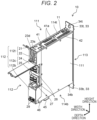
- FIG. 2 is an external view of servo amplifier device 10 according to the exemplary embodiment of the present invention.
- servo amplifier device 10 has a thin box shape in outer appearance. That is, amplifier housing 11 having a rectangular parallelepiped shape with a pair of first surfaces, a pair of second surfaces, and a pair of third surfaces forms a foundation part in the outer appearance of servo amplifier device 10.
- the pair of first surfaces are side surfaces 111 each having the largest area.
- the pair of second surfaces perpendicular to side surfaces 111, which are the first surfaces are upper surface 114t and lower surface 114b.
- the pair of third surfaces perpendicular to the first surfaces and the second surfaces are front surface 112 and back surface 113.
- a direction in which the pair of side surfaces 111 face each other will be described as a width direction
- a direction in which upper surface 114t and lower surface 114b face each other will be described as a height direction
- a direction in which front surface 112 and back surface 113 face each other will be described as a depth direction.
- a side of upper surface 114t will be described as an upper side
- a side of lower surface 114b will be described as a lower side.
- a side of front surface 112 will be described as a front side
- a side of back surface 113 will be described as a back side. Therefore, as illustrated in FIG. 2 , servo amplifier device 10 has a box shape in which the height direction and the depth direction are almost the same in the length, and the width direction is thinner than the height direction and the depth direction.
- each servo amplifier device 10 As illustrated in FIG. 1 , as a basic configuration of multiaxis servo control device 100, power supply device 50 and each servo amplifier device 10 are arranged in the width direction perpendicular to side surfaces 111 of each servo amplifier device 10. In other words, three servo amplifier devices 10 are arranged side by side in the normal direction with respect to side surfaces 111, which are the first surfaces. Therefore, as illustrated in FIG. 2 , in servo amplifier device 10, on both side surfaces 111, basically, no member is configured to be disposed except for a fixing member such as a bolt for fixing a side plate. Both side surfaces 111 are flat surfaces without a protrusion.
- back surfaces 113 of servo amplifier devices 10 are basically fixed. Therefore, attachment portion 33 for fixing servo amplifier device 10 itself to installation board 60 is provided on a side of back surface 113.
- installation board 60 is configured with base portion 61 that serves as a base when servo amplifier device 10 is disposed at an installation place, and attachment plate 62 that extends in the height direction from base portion 61 and spreads in a plate shape.
- no member is configured to be disposed on the surface of back surface 113 in a similar manner to side surfaces 111. As illustrated in FIG.
- attachment portion 33 includes, on the side of back surface 113, upper attachment portion 33t having a small area of a plate shape and extending upward in the height direction from the surface of back surface 113 of amplifier housing 11, and lower attachment portion 33b having a plate shape and extending downward in the height direction.
- Upper attachment portion 33t and lower attachment portion 33b respectively have attachment holes 34t, 34b to fix servo amplifier device 10 itself to installation board 60 using a fixing member such as a bolt or a screw.
- a fixing member such as a bolt or a screw.
- one servo amplifier device 10 is fixed to installation board 60.
- bolt 35t is screwed through attachment hole 34t
- bolt 35b is screwed through attachment hole 34b into attachment plate 62, so as to fix servo amplifier device 10 itself to installation board 60.
- attachment plate 62 screw holes are formed beforehand at positions corresponding to respective positions of attachment holes 34t, 34b, so that the work of attaching and detaching servo amplifier device 10 to and from installation board 60 is facilitated. Further, by forming a plurality of such screw holes in the lateral direction (the width direction) of attachment plate 62, an additional installation of servo amplifier device 10 is facilitated.
- I/O connector 41a is used, for example, for inputting or outputting an input signal from each type of switch or sensor or an output signal or the like for driving a relay or the like, which is mounted on a processing machine controlled by the multiaxis servo control device. Furthermore, as illustrated in FIG. 2 , heat radiation holes 42 for heat radiation and the like are formed on upper surface 114t of amplifier housing 11.
- motor driving connector 45 and encoder connector 46 are disposed on lower surface 114b of amplifier housing 11.
- Motor driving connector 45 is a connector for connecting drive line 87.
- a drive voltage is supplied from servo amplifier device 10 to motor 80 via motor driving connector 45 and drive line 87.
- Encoder connector 46 is a connector for connecting encoder line 88.
- a detection signal indicating a detection position and the like is supplied from motor 80 to servo amplifier device 10 via encoder line 88 and encoder connector 46.
- the connectors for making connections are disposed separately on the side of upper surface 114t and on the side of lower surface 114b of servo amplifier device 10 depending on the function. Therefore, as can be understood from FIG. 1 , an empty space on the side of upper surface 114t is available for each servo amplifier device 10 installed on installation board 60 for wiring of a connection with host controller 71, such as communication line 72. An empty space on the side of lower surface 114b is available for wiring of a connection between drive line 87, encoder line 88, or the like and motor 80.
- FIG. 3 is a front view illustrating front surface 112 of servo amplifier device 10.
- a configuration of front surface 112 constituting amplifier housing 11 of servo amplifier device 10 will be described with reference to FIGS. 1 , 2 , and 3 .
- front surface 112 of amplifier housing 11 is divided into front surface upper portion 112t, front surface middle portion 112c, and front surface lower portion 112b from upper surface 114t to lower surface 114b in the height direction.
- a display unit for displaying information simply with a display member, and a DC power supply connection unit for connecting a DC power supply are disposed on front surface 112.
- Front surface upper portion 112t serves as an interface area including the display unit.
- Front surface middle portion 112c which is closer to the center than the display unit is, serves as an area for power supply distribution that is the DC power supply connection unit.
- Front surface lower portion 112b In front surface lower portion 112b, at its lower part, ground terminal 29 for connecting to the ground is provided. Front surface lower portion 112b has a flat shape except for ground terminal 29.
- FIGS. 1 to 3 illustrate an example in which two seven-segment displays 23d are disposed.
- Front surface upper portion 112t includes upper door 21, which is transparent and is a vertically openable door.
- the main body side in the depth direction with respect to upper door 21, which is closed, is defined as member arrangement portion 22, in which a member for a simple interface and the like are arranged.
- member arrangement portion 22 a member for device address setting including seven-segment displays 23d and a member for a simple operation by a user are arranged.
- Upper door 21 is a door that is made of a resin and that is openable and closable in a vertically openable manner. Upper door 21 is openable and closable to rotate vertically around the vicinity of upper surface 114t, when viewed from the lateral direction.
- front surface middle portion 112c serves as DC power supply connection unit 25 to be described next. That is, a bus bar connector configured to connect the metal plate of split bus bar 55 is disposed in DC power supply connection unit 25. More specifically, split bus bar 55 is configured to be an insertion plug type.
- socket portions 26, into or from which split bus bars 55 are respectively insertable and removable are provided in the main body of servo amplifier device 10. By inserting split bus bar 55 into socket portion 26, an electrical connection is established.
- front surface middle portion 112c also includes middle door 24, which is a vertically openable door.
- the main body side in the depth direction with respect to middle door 24, which is closed, is defined as DC power supply connection unit 25.
- Socket portions 26 are disposed in DC power supply connection unit 25.
- Middle door 24 is also an openable and closable door in a vertically openable manner, and is openable and closable to rotate vertically around the vicinity the upper side of front surface middle portion 112c, when viewed from the lateral direction.
Landscapes
- Engineering & Computer Science (AREA)
- Automation & Control Theory (AREA)
- Microelectronics & Electronic Packaging (AREA)
- Power Engineering (AREA)
- Control Of Multiple Motors (AREA)
- Control Of Ac Motors In General (AREA)
Description
- The present invention relates to a servo amplifier device that controls and drives a servo motor, and a multiaxis servo control device that includes a plurality of the servo amplifier devices and that control and drive a plurality of the servo motors.
- As one of use applications of industrial servo motors, there is a processing machine having an arm configured with a plurality of axes. In such a processing machine for controlling multiple axes, usually, a plurality of servo amplifier devices (hereinafter, simply referred to as servo amplifiers, as appropriate) each for controlling and driving a servo motor are also demanded in accordance with a number of axes. For this reason, as the number of axes increases, a servo amplifier group occupies a larger space. Furthermore, wiring connected with the servo motors, wiring for servo amplifier control, and the like also increase. For this reason, a wiring process becomes complicated, and a connection error or the like easily occurs. Therefore, a multiaxis servo drive device having the purpose for, for example, improving work efficiency by simplifying the wiring has been conventionally proposed (see, for example, PTL 1).
- Such a conventional multiaxis servo drive device includes a converter unit that outputs DC power, and a plurality of servo amplifier units, each of which drives a servo motor. Each of the units includes a connector for wiring that enables a cable connection for, for example, a DC power supply or a motor power line. Furthermore, the conventional multiaxis servo drive device includes a mount base including a circuit board. On such a circuit board, a receiving-side connector corresponding to a connector of each unit is disposed, and the wiring process is also performed beforehand. The conventional multiaxis servo drive device is configured by disposing each connector of each unit so as to be fitted and connected with the receiving-side connector of the mount base.
- In the case of the conventional multiaxis servo drive device, however, in order to hold each unit, a mount base having a rack structure for accommodating each unit in a shelf frame is needed. Therefore, a number of units to be accommodated in the shelf frame is limited, and it is unsuited for a large scale of additional unit installation.
- Furthermore, in the conventional multiaxis servo drive device, the provision of a circuit board for the wiring is needed in addition to the rack structure. For this reason, as a configuration for holding each unit, a mount base dedicated to this device is needed. Therefore, it is unsuited to flexibly change the configuration, and the cost also becomes higher.
- PTL 1: Unexamined
Japanese Patent Publication No. 2005-261120
US 5,493,194 A discloses a motor control system and an electrical bus for interconnecting the components of the control system. The system includes a main motor control unit connected to four motor axis control modules. The control algorithms and commands for the system are stored and executed by the control unit which communicates control commands to the individual motor axis control modules. Each motor control module processes the control commands to control a motor connected to the module, and also communicates feedback signals produced at the associated axis to the control unit. The interconnection between the control unit and the modules is positioned at the face of the components to facilitate removal and insertion of the modules. The electrical bus includes both communications conductors and power conductors, and is included in the interconnection of the components. A portion of the system bus is supported by each of the system modules, wherein the bus is completed only if all of the system modules are in position and the connectors of each portion of the bus are engaged.
JP 2014 183711 A
CN 106 602 968 A discloses a high-power servo motor driving field and especially a servo motor driving unit structure. The servo motor driving unit structure has a special structure. The structure can be used for servo motor driving control, and is formed by function modules and a special housing structure. The housing is a book-type cuboid structure. The top surface and bottom surface of the housing structure are provided with a DC bus duct body, an mBUS interface, an MC_GPIO interface, a speed sensor interface, an MC_CNRLA interface and a motor interface, which are arranged corresponding to the corresponding function modules respectively, thereby realizing corresponding driving control functions and enabling the overall size to be smaller; besides, the overall structure is in a book shape, which facilitates modular production and joint integrated installation with other related unit modules; and the servo motor driving unit structure is of great significance to occasions (such as on a highspeed rail), where installation space is limited. - The present invention has been made to address the above drawbacks. In the present invention, a multiaxis servo control device that conducts servo control on a plurality of servo motors constituting multiple axes is achieved with a simple configuration, and has a configuration in consideration of ease of wiring. Accordingly, an object of the present invention is to provide a servo amplifier device and a multiaxis servo control device that also improve work efficiency.
- In order to achieve the above object, a servo amplifier device according to the present invention is a servo amplifier device that incorporates a control drive circuit configured to control and drive a motor, the servo amplifier device including: a housing that houses the control drive circuit; an attachment portion for attaching the housing to an installation member; a DC power supply connection unit connected with a DC power supply line to be supplied with DC power; and a communication connector connected with an external controller to be supplied with a communication signal; a motor driving connector connected with a drive line for driving the motor; and a display unit disposed with a display member. The housing has a box shape having a pair of first surfaces facing each other and each having a largest area. The communication connector and the motor driving connector are disposed on a pair of second surfaces perpendicular to the first surfaces and facing each other. On a pair of third surfaces perpendicular to the first surfaces and the second surfaces and facing each other, the attachment portion is disposed on a back surface side with one of the third surfaces being as a back surface, and the display unit and the DC power supply connection unit are disposed on a front surface with the other one of the third surfaces being as the front surface.
- With this configuration, the present servo amplifier device has only to be attached on the back surface side. Thus, this configuration eliminates the need for a dedicated installation member such as a rack structure. For example, the housing can be easily attached to a wall or an inexpensive plate-shaped installation member by using the attachment portion. Furthermore, in the case of being installed on an installation member or the like, a number of servo amplifier devices is no longer limited. In addition, the connector or the connection portion is configured to be distributed to the respective surfaces of the housing according to the function. Therefore, the work efficiency together with the ease of the wiring can be improved.
- Further, preferably, the DC power supply line is a bus bar including a metal plate, and the DC power supply connection unit is a bus bar connector configured to connect the metal plate of the bus bar.
- Further, the DC power supply connection unit is preferably disposed to be closer to a center side than the display unit is on the front surface of the housing.
- Further, preferably, the communication connector is disposed on one of the pair of second surfaces, and the motor driving connector is disposed on the other one of the pair of second surfaces.
- Further, the display unit is preferably disposed to be closer to the communication connector than the motor driving connector on the front surface of the housing.
- Further, a multiaxis servo control device according to the present invention is a multiaxis servo control device including a plurality of the above-described servo amplifier devices and configured to control and drive a plurality of the motors. The present multiaxis servo control device includes a power supply device including a DC power supply output unit that outputs the DC power, and configured to supply the DC power from the DC power supply output unit to each of the servo amplifier devices; an installation board that is the installation member for attaching the power supply device and the plurality of servo amplifier devices; and the DC power supply line that connects the DC power supply connection unit of each of the servo amplifier devices. The plurality of servo amplifier devices are arranged side by side in a normal direction with respect to the first surfaces, and are each attached to the installation board via the attachment portion provided on the back surface side of the housing.
- With such a configuration, each servo amplifier device has only to be fixed to an installation member having a simple configuration such as the installation board. Therefore, an additional installation of the servo amplifier device or a change in the arrangement configuration of the servo amplifier devices on the installation board can be easily achieved. Furthermore, in the servo amplifier device, the connectors or the connection portions are distributed according to the function to be disposed on the respective surfaces of the housing. Therefore, the wiring process can also be performed for each function by using a space above or a space below the servo amplifier devices arranged side by side in the lateral direction. Therefore, the wiring becomes easy, and a work error or the like can be suppressed.
- Further, preferably, a plurality of split bus bars each including a metal plate as the DC power supply line is further included, and the DC power supply connection units included in the servo amplifier devices adjacent to each other are connected through the split bus bar.
- Further, the power supply device according to the present invention includes: a power supply housing that houses a power supply circuit to be supplied with a commercial power supply to generate DC power; a power supply attachment portion for attaching the power supply housing to the installation board; and a DC power supply output unit that outputs the DC power. The power supply housing has a box shape having a pair of first surfaces facing each other and each having a largest area, a commercial power supply input line supplied with the commercial power supply is disposed on a pair of second surfaces perpendicular to the first surfaces and facing each other, on a pair of third surfaces perpendicular to the first surfaces and the second surfaces and facing each other, the power supply attachment portion is disposed on a back surface side with one of the third surfaces being as a back surface, and the DC power supply output unit is disposed on a front surface with the other one of the third surfaces being as the front surface.
- Further, preferably, the power supply device and the plurality of servo amplifier devices are disposed side by side in a normal direction with respect to the first surfaces of the housings of the servo amplifier devices, and are each attached to the installation board via the attachment portion provided on the back surface side of the housing of the servo amplifier device.
- In this manner, according to the present invention, a multiaxis servo control device that conducts servo control on a plurality of servo motors constituting multiple axes can be achieved with a simple configuration. In addition, it is possible to provide a servo amplifier device having a configuration in consideration of ease of wiring and also improving the work efficiency, and a multiaxis servo control device.
-
-
FIG. 1 is a configuration diagram of a multiaxis servo control system including a multiaxis servo control device provided with a plurality of servo amplifier devices according to an exemplary embodiment of the present invention. -
FIG. 2 is an external view of the servo amplifier device. -
FIG. 3 is a front view illustrating a front surface of the servo amplifier device. -
FIG. 4 is a configuration diagram in which a power supply device and the plurality of servo amplifier devices are arranged side by side in a width direction according to the exemplary embodiment of the present invention. - An exemplary embodiment of the present invention will be described with reference to the drawings. Note that the following exemplary embodiment is an example embodying the present invention.
-
FIG. 1 is a configuration diagram ofservo system 200 including multiaxisservo control device 100 provided with a plurality ofservo amplifier devices 10 according to an exemplary embodiment of the present invention. - As illustrated in
FIG. 1 ,servo system 200 includes multiaxisservo control device 100, a plurality of servo motors (hereinafter, simply referred to as motors, as appropriate) 80 to be controlled and driven by multiaxisservo control device 100, andhost controller 71 that controls eachservo amplifier device 10.FIG. 1 illustrates a configuration example of three-axis servo system 200, in which three pairs ofservo amplifier devices 10 andmotors 80 are provided with oneservo amplifier device 10 and onemotor 80 constituting one pair. - Multiaxis
servo control device 100 inservo system 200 includes threeservo amplifier devices 10,power supply device 50 that supplies DC power to eachservo amplifier device 10, andinstallation board 60 on which eachservo amplifier device 10 andpower supply device 50 are installed. - In
servo system 200, first, asmotor 80 to be controlled and driven by multiaxisservo control device 100, for example, a brushless motor is suitable in addition to the servo motor. That is, as a configuration example ofmotor 80, as illustrated by using one ofmotors 80 inFIG. 1 , a brushless motor can be mentioned. Regarding the brushless motor,stator 83 fixed tomotor housing 81,rotor 84 disposed on an inner circumferential side ofstator 83, and bearing 85 that supportsrotor 84 are housed inmotor housing 81. Here,stator 83 is formed by winding three-phase windings of a U phase, a V phase, and a W phase around a stator core.Rotor 84 holds a permanent magnet in a rotor core, and rotates aboutrotation shaft 82.Servo amplifier device 10 applies a drive voltage having a drive waveform corresponding to the control to the windings ofmotor 80, and thenrotation shaft 82 rotates. Accordingly, for example, a load connected withrotation shaft 82 is rotated bymotor 80. - In the present exemplary embodiment, the drive voltage for the rotation control as described above is supplied from
servo amplifier device 10 tomotor 80 viadrive line 87.Motor 80 includesencoder 86 for detecting the rotational position ofrotor 84. A signal fromencoder 86 is supplied toservo amplifier device 10 viaencoder line 88. - On the other hand,
servo amplifier device 10 incorporates a control drive circuit for controlling and drivingmotor 80. In order to supply the power to the control drive circuit, multiaxisservo control device 100 includespower supply device 50 for supplying the DC power to eachservo amplifier device 10.Power supply device 50 is connected withAC power supply 78, which is a commercial power supply, via commercial powersupply input line 79.Power supply device 50 converts AC power supplied fromAC power supply 78 into DC power, and supplies the DC power to eachservo amplifier device 10.Power supply device 50 houses such a DC power conversion circuit inpower supply housing 51 having a box shape. In a similar manner,servo amplifier device 10 also houses the control drive circuit inamplifier housing 11, which is a housing having a box shape.Servo amplifier device 10 uses the DC power that has been supplied frompower supply device 50 to cause the control drive circuit to conduct an electrical operation and also generate a drive voltage for drivingmotor 80. - The present exemplary embodiment is characterized in that the power is supplied by using a so-called bus bar in order to constitute a DC power supply line for supplying the DC power in this manner. The bus bar is a member used to conduct an electric current of a large capacity, and its conductive portion is configured with a conductor plate or a conductor rod formed of a metal such as copper or aluminum. Specifically, regarding the bus bar, as illustrated in
FIG. 1 , a power supply connection is accomplished by using split bus bars 55 that respectively connect devices to straddle the devices like jumper wires at the central parts on the front surfaces ofpower supply device 50 and eachservo amplifier device 10. Note that the power supply connection using split bus bars 55 will be described later in more detail. - Each
servo amplifier device 10 is connected withhost controller 71 in order to control the control drive circuit incorporated in eachservo amplifier device 10. InFIG. 1 ,host controller 71 and eachservo amplifier device 10 communicate with each other viacommunication line 72. Note that, in the present exemplary embodiment, an example of wired communication usingcommunication line 72 has been described. However, wireless communication may be configured. - As a specific example of
host controller 71, for example, a personal computer can be used in a case of parameter settings or the like, and a programmable logic controller (PLC) or a motion controller can be used in a case of giving an action command for instructing the rotation position, the speed, or the like. Further, as a specific communication method in this communication, for example, data communication compliant with a serial communication standard such as RS232C/485, a universal serial bus (USB) standard, or realtime express (RTEX) or EtherCAT (registered trademark) communication, which is a communication specification dedicated to a factory automation (FA) network, is also suitable. By such a connection betweenhost controller 71 and eachservo amplifier device 10,host controller 71 sends various types of information including an action command to eachservo amplifier device 10, and also receives various types of information from eachservo amplifier device 10, such thatmotor 80 conducts a desired action. For example, in a case whereservo amplifier device 10 controls the position ofrotor 84 included inmotor 80,host controller 71 notifies of a target position command, and in a case where the speed ofrotor 84 is controlled,host controller 71 notifies of a target speed command. - Each
servo amplifier device 10 controls and drives the motion and action ofmotor 80, based on the action command fromhost controller 71. Therefore,servo amplifier device 10 includes a controller and a drive unit each being as a main circuit configuration. The main operation of the controller includes functions of feedback control as follows. That is, the controller is supplied with a command signal indicating an action command fromhost controller 71 as described above viacommunication line 72, and a detection signal indicating the position or speed that has been detected byencoder 86 fromencoder 86 ofmotor 80 viaencoder line 88. The controller generates a control signal using such a command signal and such a detection signal, based on, for example, the feedback control, and controls the action ofmotor 80 such that the motion position or the speed ofmotor 80 follows the action command. Specifically, the controller is preferably, for example, the central processing unit (CPU) or a microcomputer incorporating a memory in which a program is stored. The drive unit includes a so-called inverter. The inverter is configured with power conversion elements such as a switching element and a diode. The inverter uses these elements to generate a drive voltage having a drive waveform corresponding to the control signal. This drive voltage is supplied to the windings ofmotor 80 viadrive line 87. Accordingly, the windings ofmotor 80 are energized, androtor 84 androtation shaft 82 inmotor 80 rotate. -
FIG. 2 is an external view ofservo amplifier device 10 according to the exemplary embodiment of the present invention. - A configuration of
servo amplifier device 10 will be described in detail with reference toFIGS. 1 and2 . As illustrated inFIG. 2 ,servo amplifier device 10 has a thin box shape in outer appearance. That is,amplifier housing 11 having a rectangular parallelepiped shape with a pair of first surfaces, a pair of second surfaces, and a pair of third surfaces forms a foundation part in the outer appearance ofservo amplifier device 10. As illustrated inFIG. 1 , the pair of first surfaces areside surfaces 111 each having the largest area. As illustrated inFIG. 1 , the pair of second surfaces perpendicular toside surfaces 111, which are the first surfaces, areupper surface 114t andlower surface 114b. As illustrated inFIG. 1 , the pair of third surfaces perpendicular to the first surfaces and the second surfaces arefront surface 112 andback surface 113. - Hereinafter, a direction in which the pair of side surfaces 111 face each other will be described as a width direction, a direction in which
upper surface 114t andlower surface 114b face each other will be described as a height direction, and a direction in whichfront surface 112 andback surface 113 face each other will be described as a depth direction. In particular, for convenience, in the height direction illustrated inFIG. 2 , a side ofupper surface 114t will be described as an upper side, and a side oflower surface 114b will be described as a lower side. In a similar manner, in the depth direction, a side offront surface 112 will be described as a front side, and a side ofback surface 113 will be described as a back side. Therefore, as illustrated inFIG. 2 ,servo amplifier device 10 has a box shape in which the height direction and the depth direction are almost the same in the length, and the width direction is thinner than the height direction and the depth direction. - Next, a detailed configuration of the respective surfaces constituting the outer shape of
servo amplifier device 10 will be described. - As illustrated in
FIG. 1 , as a basic configuration of multiaxisservo control device 100,power supply device 50 and eachservo amplifier device 10 are arranged in the width direction perpendicular toside surfaces 111 of eachservo amplifier device 10. In other words, threeservo amplifier devices 10 are arranged side by side in the normal direction with respect toside surfaces 111, which are the first surfaces. Therefore, as illustrated inFIG. 2 , inservo amplifier device 10, on both side surfaces 111, basically, no member is configured to be disposed except for a fixing member such as a bolt for fixing a side plate. Both side surfaces 111 are flat surfaces without a protrusion. - In multiaxis
servo control device 100, back surfaces 113 ofservo amplifier devices 10 are basically fixed. Therefore,attachment portion 33 for fixingservo amplifier device 10 itself toinstallation board 60 is provided on a side ofback surface 113. As an installation member for installingservo amplifier device 10, as illustrated inFIG. 1 ,installation board 60 is configured withbase portion 61 that serves as a base whenservo amplifier device 10 is disposed at an installation place, andattachment plate 62 that extends in the height direction frombase portion 61 and spreads in a plate shape. In order to fix backsurface 113 ofservo amplifier device 10 toinstallation board 60, no member is configured to be disposed on the surface ofback surface 113 in a similar manner to side surfaces 111. As illustrated inFIG. 2 ,attachment portion 33 includes, on the side ofback surface 113,upper attachment portion 33t having a small area of a plate shape and extending upward in the height direction from the surface ofback surface 113 ofamplifier housing 11, andlower attachment portion 33b having a plate shape and extending downward in the height direction.Upper attachment portion 33t andlower attachment portion 33b respectively haveattachment holes servo amplifier device 10 itself toinstallation board 60 using a fixing member such as a bolt or a screw. On the basis of such a configuration, the surface ofback surface 113 ofservo amplifier device 10 is aligned with the surface ofattachment plate 62 at a predetermined position ofattachment plate 62, and bolt or the like is inserted into each ofattachment holes servo amplifier device 10 is fixed toinstallation board 60. InFIG. 1 ,bolt 35t is screwed throughattachment hole 34t, andbolt 35b is screwed throughattachment hole 34b intoattachment plate 62, so as to fixservo amplifier device 10 itself toinstallation board 60. Further, inattachment plate 62, screw holes are formed beforehand at positions corresponding to respective positions ofattachment holes servo amplifier device 10 to and frominstallation board 60 is facilitated. Further, by forming a plurality of such screw holes in the lateral direction (the width direction) ofattachment plate 62, an additional installation ofservo amplifier device 10 is facilitated. - As illustrated in
FIG. 2 , inservo amplifier device 10,communication connector 41 is disposed onupper surface 114t ofamplifier housing 11.Communication connector 41 is a connector for connectingcommunication line 72. Tocommunication connector 41, a communication signal is supplied fromhost controller 71 toservo amplifier device 10 viacommunication line 72 andcommunication connector 41.FIG. 2 illustrates an example in which a plurality of types ofcommunication connectors 41 compliant with each communication type or specification are arranged onupper surface 114t. I/O (input/output)connector 41a is disposed onupper surface 114t ofamplifier housing 11. I/O connector 41a is used, for example, for inputting or outputting an input signal from each type of switch or sensor or an output signal or the like for driving a relay or the like, which is mounted on a processing machine controlled by the multiaxis servo control device. Furthermore, as illustrated inFIG. 2 , heat radiation holes 42 for heat radiation and the like are formed onupper surface 114t ofamplifier housing 11. - In
servo amplifier device 10,motor driving connector 45 andencoder connector 46 are disposed onlower surface 114b ofamplifier housing 11.Motor driving connector 45 is a connector for connectingdrive line 87. A drive voltage is supplied fromservo amplifier device 10 tomotor 80 viamotor driving connector 45 and driveline 87.Encoder connector 46 is a connector for connectingencoder line 88. A detection signal indicating a detection position and the like is supplied frommotor 80 toservo amplifier device 10 viaencoder line 88 andencoder connector 46. - In this manner, in the present exemplary embodiment, the connectors for making connections are disposed separately on the side of
upper surface 114t and on the side oflower surface 114b ofservo amplifier device 10 depending on the function. Therefore, as can be understood fromFIG. 1 , an empty space on the side ofupper surface 114t is available for eachservo amplifier device 10 installed oninstallation board 60 for wiring of a connection withhost controller 71, such ascommunication line 72. An empty space on the side oflower surface 114b is available for wiring of a connection betweendrive line 87,encoder line 88, or the like andmotor 80. In this manner, in the present exemplary embodiment, regarding the arrangements of the connectors and the space for the wiring process associated with such arrangements, the side ofupper surface 114t and the side oflower surface 114b ofservo amplifier device 10 are separated depending on the function. Accordingly, ease of wiring is achieved, and work efficiency in line processing is also improved. -
FIG. 3 is a front view illustratingfront surface 112 ofservo amplifier device 10. A configuration offront surface 112 constitutingamplifier housing 11 ofservo amplifier device 10 will be described with reference toFIGS. 1 ,2 , and3 . As illustrated inFIGS. 1 to 3 ,front surface 112 ofamplifier housing 11 is divided into front surfaceupper portion 112t, front surfacemiddle portion 112c, and front surfacelower portion 112b fromupper surface 114t tolower surface 114b in the height direction. In brief, onfront surface 112, a display unit for displaying information simply with a display member, and a DC power supply connection unit for connecting a DC power supply are disposed. Front surfaceupper portion 112t serves as an interface area including the display unit. Front surfacemiddle portion 112c, which is closer to the center than the display unit is, serves as an area for power supply distribution that is the DC power supply connection unit. - In front surface
lower portion 112b, at its lower part,ground terminal 29 for connecting to the ground is provided. Front surfacelower portion 112b has a flat shape except forground terminal 29. - In front surface
upper portion 112t, seven-segment display 23d as a display member is disposed to constitute the display unit.FIGS. 1 to 3 illustrate an example in which two seven-segment displays 23d are disposed. - A more specific configuration of front surface
upper portion 112t will be described. Front surfaceupper portion 112t includesupper door 21, which is transparent and is a vertically openable door. The main body side in the depth direction with respect toupper door 21, which is closed, is defined asmember arrangement portion 22, in which a member for a simple interface and the like are arranged. Inmember arrangement portion 22, a member for device address setting including seven-segment displays 23d and a member for a simple operation by a user are arranged.Upper door 21 is a door that is made of a resin and that is openable and closable in a vertically openable manner.Upper door 21 is openable and closable to rotate vertically around the vicinity ofupper surface 114t, when viewed from the lateral direction. An operation unit is attached tomember arrangement portion 22 such that an operation forservo amplifier device 10 is enabled withupper door 21 opened. More specifically,member arrangement portion 22 is equipped withrotary switch 23s, a USB connector, and the like, in addition to seven-segment displays 23d. By closingupper door 21, front surfaceupper portion 112t becomes a flat surface, and as illustrated inFIGS. 1 and3 , the display of seven-segment displays 23d that emit light becomes visible throughupper door 21. - In front surface
middle portion 112c, as described above, split bus bars 55 that connect the devices are used for constituting the DC power supply line for supplying the DC power so as to supply the power to eachservo amplifier device 10. For this reason, inservo amplifier device 10, front surfacemiddle portion 112c serves as DC powersupply connection unit 25 to be described next. That is, a bus bar connector configured to connect the metal plate ofsplit bus bar 55 is disposed in DC powersupply connection unit 25. More specifically, splitbus bar 55 is configured to be an insertion plug type. In front surfacemiddle portion 112c, as bus bar connectors,socket portions 26, into or from which split bus bars 55 are respectively insertable and removable, are provided in the main body ofservo amplifier device 10. By inserting splitbus bar 55 intosocket portion 26, an electrical connection is established. - A more specific configuration of front surface
middle portion 112c will be described below. That is, in a similar manner to front surfaceupper portion 112t, front surfacemiddle portion 112c also includesmiddle door 24, which is a vertically openable door. The main body side in the depth direction with respect tomiddle door 24, which is closed, is defined as DC powersupply connection unit 25.Socket portions 26 are disposed in DC powersupply connection unit 25.Middle door 24 is also an openable and closable door in a vertically openable manner, and is openable and closable to rotate vertically around the vicinity the upper side of front surfacemiddle portion 112c, when viewed from the lateral direction. - In front surface
middle portion 112c, twosocket portions 26, into each of which splitbus bar 55 is insertable and removeable, are disposed.FIG. 1 illustrates a view ofservo amplifier device 10 withmiddle door 24 closed, when viewed from the front surface. InFIG. 1 , a state in which split bus bars 55 are respectively attached tosocket portions 26 are each indicated by a broken line.FIG. 2 illustrates a state in which nosplit bus bar 55 is attached.FIG. 3 illustrates a state in which split bus bars 55 are attached only to one sides of bothsocket portions 26. In the following, a detailed configuration in DC powersupply connection unit 25 will be described with reference to these drawings. - One of two
socket portions 26 serves as a high-voltage DC power supply. Onesocket portion 26 is for, for example, rectifying an AC commercial power supply voltage into a DC, and supplying a stabilized DC voltage of a hundred and several tens volts to several hundred volts. This high-voltage DC power is mainly supplied to the drive unit ofservo amplifier device 10 to be used for drivingmotor 80. Anothersocket portion 26 serves as a low-voltage DC power supply. Anothersocket portion 26 is, for example, a DC voltage of more than or equal to five volts and less than or equal to 30 volts. This low-voltage DC power is mainly supplied to the controller ofservo amplifier device 10 to be used for controllingmotor 80. -
Socket portion 26 includes a pair of a positive electrode side terminal and a negative electrode side terminal at a DC voltage to be supplied, an input side terminal, and an output side terminal.Socket portion 26 includes four terminals in total. - Specifically, as illustrated in
FIG. 3 ,socket portion 26H, which issocket portion 26 closer to front surfaceupper portion 112t, is configured for the high-voltage DC power supply, whereassocket portion 26L, which issocket portion 26 closer to front surfacelower portion 112b, is configured for the low-voltage DC power supply. Insocket portion 26, a pair of terminals on one side in the lateral direction serve as the input side terminal, and a pair of terminals on the other side in the lateral direction serve as the output side terminal. InFIG. 3 , a terminal on a side with which nosplit bus bar 55 is connected is configured as an input side terminal, and a terminal on a side with which splitbus bar 55 is connected is configured as an output side terminal. With the present configuration, insocket portion 26H, a high positive voltage DC+ is supplied to a positive electrode terminal on the input side, and a high negative voltage DC-is input into a negative electrode terminal on the input side. The high positive voltage DC+ is output from a positive electrode terminal on the output side, and the high negative voltage DC- is output from a negative electrode terminal on the output side. In a similar manner, insocket portion 26L, a low positive voltage Vcc+ and a low negative voltage Vcc- are input into a terminal on the input side, and the low positive voltage Vcc+ and the low negative voltage Vcc-are output from a terminal on the output side. - As described above, in the present exemplary embodiment, split
bus bar 55 is configured to be insertable and removable into and fromsocket portion 26. In order to enable this insertion and removal, the four terminals insocket portion 26 serve asblade receiving portion 27 having a structure in which twometal plates 27b each having a spring property are brought into face-to-face contact. - To correspond to
socket portion 26, splitbus bar 55 is configured with twometal bars 55b each being formed of a metal plate, and bar holdingportion 55r that holds twometal bars 55b respectively at two positions. As illustrated inFIG. 3 ,metal bars 55b respectively correspond to the positive side and the negative side ofsocket portion 26. Bar holdingportions 55r respectively correspond to the input side and the output side ofsocket portion 26.Metal bar 55b includes protruding blades (not illustrated) that protrude frommetal bar 55b in a direction opposite to bar holdingportion 55r in the vicinity of both ends of eachmetal bar 55b. That is, by inserting the protruding blade ofsplit bus bar 55 intoblade receiving portion 27 ofsocket portion 26, twometal plates 27b ofblade receiving portion 27 sandwich the protruding blade. Accordingly,metal bar 55b andblade receiving portion 27 are electrically connected with each other. -
FIG. 3 illustrates a state in which split bus bars 55 are respectively inserted into the output sides ofsocket portions 26, based on the above configuration. As illustrated inFIG. 3 , splitbus bar 55 is connected across the output side of certainservo amplifier device 10 and the input side ofservo amplifier device 10, which is adjacent. Accordingly, the DC power is supplied betweenservo amplifier devices 10 adjacent to each other. That is, by sequentially connecting split bus bars 55 in an adjacent direction, the DC power supply line for supplying the DC power to eachservo amplifier device 10 can be configured. In this manner, in the present exemplary embodiment, the power supply is configured to be a bus bar type. Therefore, the power supply is enabled in a simple operation of inserting splitbus bar 55 without complexity and poor work efficiency in the wiring process, such as entanglement of lines. After insertion ofsplit bus bar 55 is completed,middle door 24 is closed, so that safety such as prevention of electric shock can be easily ensured. - Next, a detailed description will be given with regard to multiaxis
servo control device 100 configured by using a plurality ofservo amplifier devices 10 each having the above-described configuration. - The outline has been described above. As illustrated in
FIG. 1 , multiaxisservo control device 100 is configured by installing a plurality ofservo amplifier devices 10 and onepower supply device 50 that supplies the DC power to each ofservo amplifier devices 10, oninstallation board 60. In addition,power supply device 50 andservo amplifier devices 10 have the same dimension in the height direction,power supply device 50 andservo amplifier devices 10 have the same dimension in the depth direction, andpower supply device 50 is disposed at an end in the width direction with respect to the plurality ofservo amplifier devices 10.FIG. 4 is a configuration diagram in whichpower supply device 50 and the plurality ofservo amplifier devices 10 according to the exemplary embodiment of the present invention are arranged side by side in the width direction. - In such multiaxis
servo control device 100, the configuration of eachservo amplifier device 10 has been described above. A configuration ofpower supply device 50 will be described. - As illustrated in
FIG. 4 ,power supply device 50 disposed side by side with respectiveservo amplifier devices 10 also has a thin box shape in the outer appearance in a similar manner toservo amplifier devices 10. That is, inpower supply device 50,power supply housing 51 having a rectangular parallelepiped shape including a pair of first surfaces, a pair of second surfaces, and a pair of third surfaces forms the foundation part in the outer appearance. A power supply circuit that generates the DC power is housed inpower supply housing 51. Then, in a similar manner toservo amplifier devices 10, the pair of first surfaces are side surfaces each having the largest area, the second surfaces are the upper surface and the lower surface, and the third surfaces are the front surface and the back surface.FIG. 4 illustrates a state in whichpower supply device 50 is viewed from the front surface. - In a similar manner to
servo amplifier devices 10, both side surfaces ofpower supply device 50 are basically configured such that no member is disposed except for a fixing member such as a bolt for fixing a side plate. Both side surfaces are flat surfaces without a protrusion. In a similar manner toservo amplifier devices 10, no member is configured to be disposed on the back surface ofpower supply device 50. Similar toservo amplifier devices 10,attachment portion 33 includingupper attachment portion 33t andlower attachment portion 33b is provided as a power supply attachment portion to be attached to the installation member.Upper attachment portion 33t andlower attachment portion 33b respectively haveattachment holes attachment holes power supply device 50 is fixed toinstallation board 60. Inpower supply device 50, from its lower surface, commercial powersupply input line 79 to be connected withAC power supply 78 is drawn out. - Front surface of
power supply device 50 has a configuration as illustrated inFIG. 4 . In a similar manner toservo amplifier device 10, the front surface ofpower supply device 50 is also divided into front surfaceupper portion 512t, front surfacemiddle portion 512c, and front surfacelower portion 512b from the upper surface side toward the lower surface side in the height direction. The dimensions in the height direction of front surfaceupper portion 512t, front surfacemiddle portion 512c, and front surfacelower portion 512b also coincide with front surfaceupper portions 112t, front surfacemiddle portions 112c, and front surfacelower portions 112b ofservo amplifier devices 10. - In front surface
lower portion 512b ofpower supply device 50,ground terminal 29 is provided at a lower part of front surfacelower portion 512b, in a similar manner toservo amplifier devices 10. Front surfacelower portion 512b has a flat surface except forground terminal 29.Power supply device 50 is configured such that nothing is disposed on front surfaceupper portion 512t, so that front surfaceupper portion 512t has a flat surface. - As can be understood from the above description, in front surface
middle portion 512c ofpower supply device 50, the DC power is supplied by using split bus bars 55. That is, as illustrated inFIGS. 1 and4 , the DC power supply lines are formed in the width direction in front surfacemiddle portion 512c ofpower supply device 50 and front surfacemiddle portion 112c of eachservo amplifier device 10. The DC power output frompower supply device 50 is supplied to eachservo amplifier device 10 via the DC power supply lines configured as described above. - Amore specific configuration of front surface
middle portion 512c will be described next. That is,power supply device 50 includesmiddle door 524, which is a vertically openable door, in front surfacemiddle portion 512c. The main body side in the depth direction with respect tomiddle door 524, which is closed, is defined as DC powersupply output unit 525. In a similar manner toservo amplifier devices 10, twosocket portions 26 are disposed in DC powersupply output unit 525. Note thatFIG. 4 illustratespower supply device 50 in a state in whichmiddle door 524 is opened such that DC powersupply output unit 525 can be seen.Servo amplifier device 10 adjacent topower supply device 50 indicates a state in whichmiddle door 24 is opened, and two otherservo amplifier devices 10 indicate a state in whichmiddle door 24 is closed. - In two
socket portions 26 ofpower supply device 50, onesocket portion 26 on the upper side is used for outputting a high-voltage DC power supply, and for example, a DC voltage of a hundred and several tens volts to several hundred volts is output. Anothersocket portion 26 on the lower side is used for outputting a low-voltage DC power supply, and for example, a DC voltage of more than or equal to five volts to less than or equal to 30 volts is output. In this manner, DC powersupply output unit 525 that outputs the DC power usingsocket portions 26 is disposed in front surfacemiddle portion 512c ofpower supply device 50. -
FIG. 4 illustrates a state in which split bus bars 55 are respectively inserted intosocket portions 26 ofpower supply device 50 andservo amplifier device 10. Here, an example in whichsocket portion 26 inpower supply device 50 is only used for outputting the power supply is illustrated, and splitbus bar 55p having a different shape from splitbus bar 55c for connecting betweenservo amplifier devices 10. In the following, a description will be given by also referring to the configuration and the like ofblade receiving portion 27 illustrated inFIG. 3 . Insplit bus bar 55c,bar holding portions 55r on both sides respectively correspond to twoblade receiving portions 27. Insplit bus bar 55p,bar holding portion 55r on one side corresponds to fourblade receiving portions 27, and bar holdingportion 55r on the other side corresponds to twoblade receiving portions 27. As illustrated inFIGS. 1 and4 , splitbus bar 55p is used for connecting frompower supply device 50 toservo amplifier device 10, and splitbus bar 55c is used for connecting betweenservo amplifier devices 10 to constitute the DC power supply line. - As described above, as illustrated in
FIG. 1 , multiaxisservo control device 100 according to the present exemplary embodiment has a configuration in whichpower supply device 50 and the plurality ofservo amplifier devices 10, which have been described above, are arranged side by side in the width direction on the plate surface ofinstallation board 60, and are attached through bolt-fixing usingattachment portion 33. Multiaxisservo control device 100 has such a simple configuration, and thus easily enables an additional installation ofservo amplifier device 10 or a change in the arrangement configuration ofservo amplifier device 10 oninstallation board 60. The DC power supply line for supplying the DC power is configured on front surface 512 ofpower supply device 50 andfront surfaces 112 of the plurality ofservo amplifier devices 10.Communication connector 41 is disposed onupper surface 114t, andmotor driving connector 45 andencoder connector 46 are disposed onlower surface 114b. Therefore, an empty space on the side ofupper surface 114t is available for eachservo amplifier device 10 for wiring of connection withhost controller 71, such ascommunication line 72. An empty space on the side oflower surface 114b is available for wiring of connection withmotor 80, such asdrive line 87 orencoder line 88. In this manner, according to the present exemplary embodiment, the wiring process can be performed for each function. Therefore, the wiring becomes easy, and a work error or the like can be suppressed. - As described above,
servo amplifier device 10 according to the present exemplary embodiment isservo amplifier device 10 that incorporates a control drive circuit configured to control and drivemotor 80, and includes a housing corresponding to amplifierhousing 11 that houses the control drive circuit,attachment portion 33 for attaching the housing to an installation member, DC powersupply connection unit 25 connected with the DC power supply line to be supplied with DC power,communication connector 41 connected with an external controller corresponding to hostcontroller 71 to be supplied with a communication signal,motor driving connector 45 connected with the drive line that drivesmotor 80, and the display unit disposed with the display member. The housing has a box shape having a pair offirst surfaces 111 facing each other and each having the largest area.Communication connector 41 andmotor driving connector 45 are disposed on a pair ofsecond surfaces first surfaces 111 and which face each other. In a pair ofthird surfaces first surfaces 111 andsecond surfaces third surfaces back surface 113, andattachment portion 33 is disposed closer to backsurface 113. The other one ofthird surfaces front surface 112, and the display unit and DC powersupply connection unit 25 are disposed onfront surface 112. - With this configuration, this
servo amplifier device 10 has only to be attached on a side ofback surface 113. Thus, this configuration eliminates the need for a dedicated installation member such as a rack structure. For example, the housing can be easily attached to a wall or an inexpensive plate-shaped installation member by usingattachment portion 33. Furthermore, in being installed on an installation member or the like, a number ofservo amplifier devices 10 is no longer limited. In addition, the connector or the connection portion is configured to be distributed to the respective surfaces of the housing according to the function. Therefore, the work efficiency together with the ease of the wiring can be improved. - In addition, the DC power supply line is preferably a bus bar including a metal plate, and DC power
supply connection unit 25 is a bus bar connector configured to connect the metal plate of the bus bar. - Further, DC power
supply connection unit 25 is preferably disposed to be closer to the center side than the display unit is onfront surface 112 of the housing. - Further, preferably,
communication connector 41 is disposed on one surface of the pair ofsecond surfaces motor driving connector 45 is disposed on the other one of the pair ofsecond surfaces - Further, the display unit is preferably disposed to be closer to
communication connector 41 thanmotor driving connector 45 onfront surface 112 of the housing. - Further, multiaxis
servo control device 100 according to the present exemplary embodiment is a multiaxisservo control device 100 including a plurality ofservo amplifier devices 10 and configured to control and drive a plurality ofmotors 80. This multiaxisservo control device 100 includespower supply device 50 including DC powersupply output unit 525 that outputs the DC power, and configured to supply the DC power from DC powersupply output unit 525 to each ofservo amplifier devices 10,installation board 60, which is the installation member for attachingpower supply device 50 and the plurality ofservo amplifier devices 10; and the DC power supply line that connects DC powersupply connection unit 25 of each ofservo amplifier devices 10. The plurality ofservo amplifier devices 10 are arranged side by side in a normal direction with respect tofirst surfaces 111, and are each attached toinstallation board 60 viaattachment portion 33 provided closer to backsurface 113 of the housing. - With such a configuration, each
servo amplifier device 10 has only to be fixed to the installation member having a simple configuration such asinstallation board 60. Therefore, an additional installation ofservo amplifier device 10 or a change in the arrangement configuration ofservo amplifier devices 10 on the installation board can be easily achieved. Furthermore, inservo amplifier device 10, connectors or connection portions are distributed according to the function to be disposed on the respective surfaces of the housing. Therefore, the wiring process can also be performed for each function, by using a space above or a space belowservo amplifier devices 10 arranged in the lateral direction. Therefore, the wiring becomes easy, and a work error or the like can be suppressed. - In addition, preferably, a plurality of split bus bars 55 each including a metal plate as the DC power supply line is further included, and DC power
supply connection units 25 included inservo amplifier devices 10 adjacent to each other are connected through splitbus bar 55. - Further,
power supply device 50 according to the present exemplary embodiment includespower supply housing 51, which houses a power supply circuit to be supplied with a commercial power supply to generate DC power, a power supply attachment portion corresponding toattachment portion 33 for attachingpower supply housing 51 toinstallation board 60, and DC powersupply output unit 525 that outputs the DC power.Power supply housing 51 has a box shape having a pair offirst surfaces 111 facing each other and each having a largest area, commercial powersupply input line 79 to be supplied with the commercial power supply is disposed on a pair ofsecond surfaces first surfaces 111 and facing each other, on a pair ofthird surfaces first surfaces 111 andsecond surfaces surface 113 with one ofthird surfaces back surface 113, and DC powersupply output unit 525 is disposed onfront surface 112 with the other one ofthird surfaces front surface 112. - Further, preferably,
power supply device 50 and the plurality ofservo amplifier devices 10 are disposed side by side in a normal direction with respect tofirst surfaces 111, and are each attached to the installation board viaattachment portion 33 provided closer to backsurface 113 of the housing. - In this manner, according to the present exemplary embodiment, multiaxis
servo control device 100 that performs servo control on the plurality of servo motors constituting multiple axes is achieved with a simple configuration. In addition,servo amplifier device 10 and multiaxisservo control device 100 in which work efficiency is improved by a configuration in consideration of ease of wiring can be provided. - A servo amplifier device and a multiaxis servo control device in the present invention are capable of controlling and driving a multiaxis motor with an easy configuration. Therefore, the present invention is useful for, for example, a semiconductor manufacturing apparatus and an electronic component mounting machine.
-
- 10: servo amplifier device
- 11: amplifier housing
- 21: upper door
- 22: member arrangement portion
- 23d: seven-segment display
- 23s: rotary switch
- 24, 524: middle door
- 25: DC power supply connection unit
- 26, 26H, 26L: socket portion
- 27: blade receiving portion
- 27b: metal plate
- 29: ground terminal
- 33: attachment portion
- 33b: lower attachment portion
- 33t: upper attachment portion
- 34b, 34t: attachment hole
- 35b, 35t: bolt
- 41: communication connector
- 41a: I/O connector
- 42: heat radiation hole
- 45: motor driving connector
- 46: encoder connector
- 50: power supply device
- 51: power supply housing
- 55, 55c, 55p: split bus bar
- 55b: metal bar
- 55r: bar holding portion
- 60: installation board
- 61: base portion
- 62: attachment plate
- 71: host controller
- 72: communication line
- 78: AC power supply
- 79: commercial power supply input line
- 80: motor
- 81: motor housing
- 82: rotation shaft
- 83: stator
- 84: rotor
- 85: bearing
- 86: encoder
- 87: drive line
- 88: encoder line
- 100: multiaxis servo control device
- 111: side surface (first surface)
- 112, 512: front surface (third surface)
- 112t, 512t: front surface upper portion
- 112b, 512b: front surface lower portion
- 112c, 512c: front surface middle portion
- 113: back surface (third surface)
- 114b: lower surface (second surface)
- 114t: upper surface (second surface)
- 200: servo system
- 525: DC power supply output unit
Claims (9)
- A servo amplifier device (10) that incorporates a control drive circuit configured to control and drive a motor (80), the servo amplifier device (10) comprising:a housing that houses the control drive circuit;an attachment portion (33) for attaching the housing to an installation member;a DC power supply connection unit (25) connected with a DC power supply line to be supplied with DC power;a communication connector (41) connected with an external controller to be supplied with a communication signal;a motor driving connector (45) connected with a drive line (87) for driving the motor (80); anda display unit disposed with a display member,whereinthe housing has a box shape having a pair of first surfaces (111) facing each other and each having a largest area,the communication connector (41) and the motor driving connector (45) are disposed on a pair of second surfaces (114b, 114t) perpendicular to the first surfaces (111) and facing each other,on a pair of third surfaces (112, 113) perpendicular to the first surfaces (111) and the second surfaces (114b, 114t) and facing each other, the attachment portion (33) is disposed on a back surface (113) side with one of the third surfaces (112, 113) being as a back surface (113), andthe display unit and the DC power supply connection unit (25) are disposed on a front surface (112) with another one of the third surfaces (112, 113) being as the front surface (112).
- The servo amplifier device (10) according to claim 1, whereinthe DC power supply line is a bus bar including a metal plate, andthe DC power supply connection unit (25) is a bus bar connector configured to connect the metal plate of the bus bar.
- The servo amplifier device (10) according to claim 1, wherein the DC power supply connection unit (25) is disposed to be closer to a center side than the display unit is on the front surface (112) of the housing.
- The servo amplifier device (10) according to claim 1, wherein the communication connector (41) is disposed on one of the pair of second surfaces (114b, 114t), and the motor driving connector (45) is disposed on another one of the pair of second surfaces (114b, 114t).
- The servo amplifier device (10) according to claim 1, wherein the display unit is disposed to be closer to the communication connector (41) than the motor driving connector (45) on the front surface of the housing.
- A multiaxis servo control device (100) comprising a plurality of the servo amplifier devices (10) according to any one of claims 1 to 5, and configured to control and drive a plurality of the motors (80), the multiaxis servo control device (100) comprising:a power supply device (50) including a DC power supply output unit (525) that outputs the DC power, and configured to supply the DC power from the DC power supply output unit (525) to each of the plurality of the servo amplifier devices (10);an installation board (60) that is the installation member for attaching the power supply device (50) and the plurality of the servo amplifier devices (10); andthe DC power supply line that connects the DC power supply connection unit (25) of each of the plurality of the servo amplifier devices (10), wherein the plurality of the servo amplifier devices (10) are arranged side by side in a normal direction with respect to the first surfaces (111), and are attached to the installation board (60) via the attachment portion (33) provided on the back surface (113) side of the housing.
- The multiaxis servo control device (100) according to claim 6, further comprising a plurality of split bus bars (55) each including a metal plate as the DC power supply line,
wherein the DC power supply connection units (25) included in the servo amplifier devices (10) adjacent to each other are connected through each of the plurality of split bus bars (55). - The multiaxis servo control device (100) according to claim 6, wherein
the power supply device (50) includes:a power supply housing (51) that houses a power supply circuit to be supplied with a commercial power supply to generate DC power;a power supply attachment portion for attaching the power supply housing (51) to the installation board (60); anda DC power supply output unit (525) that outputs the DC power,the power supply housing (51) has a box shape having a pair of first surfaces (111) facing each other and each having a largest area,a commercial power supply input line (79) to be supplied with the commercial power supply is disposed on a pair of second surfaces (114b, 114t) perpendicular to the first surfaces (111) of the power supply housing (51) of the power supply device (50) and facing each other,on a pair of third surfaces (112, 113) perpendicular to the first surfaces (111) of the power supply housing (51) of the power supply device (50) and the second surfaces (114b, 114t) of the power supply housing (51) of the power supply device (50) and facing each other, the power supply attachment portion is disposed on a back surface (113) side of the power supply housing (51) of the power supply device (50) with one of the third surfaces (112, 113) of the power supply housing (51) of the power supply device (50) being as a back surface (113), andthe DC power supply output unit is disposed on a front surface (112) of the power supply housing (51) of the power supply device (50) with another one of the third surfaces (112, 113) of the power supply housing (51) of the power supply device (50) being as the front surface. - The multiaxis servo control device (100) according to claim 8, wherein the power supply device (50) and the plurality of the servo amplifier devices (10) are disposed side by side in a normal direction with respect to the first surfaces (111) of the housings of the plurality of the servo amplifier devices (10), and are each attached to the installation board (60) via the attachment portion (33) provided on the back surface (113) side of the housing of each of the plurality of the servo amplifier device (10).
Applications Claiming Priority (2)
| Application Number | Priority Date | Filing Date | Title |
|---|---|---|---|
| JP2019083528 | 2019-04-25 | ||
| PCT/JP2020/011110 WO2020217765A1 (en) | 2019-04-25 | 2020-03-13 | Servo amplifier device, and multiaxis servo control device |
Publications (3)
| Publication Number | Publication Date |
|---|---|
| EP3961908A1 EP3961908A1 (en) | 2022-03-02 |
| EP3961908A4 EP3961908A4 (en) | 2022-06-15 |
| EP3961908B1 true EP3961908B1 (en) | 2025-07-09 |
Family
ID=72942525
Family Applications (1)
| Application Number | Title | Priority Date | Filing Date |
|---|---|---|---|
| EP20795084.1A Active EP3961908B1 (en) | 2019-04-25 | 2020-03-13 | Servo amplifier device, and multiaxis servo control device |
Country Status (4)
| Country | Link |
|---|---|
| EP (1) | EP3961908B1 (en) |
| JP (1) | JP7411871B2 (en) |
| CN (1) | CN113826316A (en) |
| WO (1) | WO2020217765A1 (en) |
Family Cites Families (12)
| Publication number | Priority date | Publication date | Assignee | Title |
|---|---|---|---|---|
| JP3435716B2 (en) * | 1992-01-31 | 2003-08-11 | 松下電器産業株式会社 | Multi-axis synchronous rotating device |
| JPH0657093U (en) * | 1993-01-08 | 1994-08-05 | 三木プーリ株式会社 | Control unit for multiple motors |
| JPH07143626A (en) * | 1993-11-12 | 1995-06-02 | Mutsuo Hamaguchi | Electric control board and controller unit used for this board |
| JPH08205556A (en) * | 1995-01-25 | 1996-08-09 | Sankyo Seiki Mfg Co Ltd | Multiaxis motor controller |
| US5493194A (en) * | 1995-02-14 | 1996-02-20 | Allen-Bradley Company, Inc. | Control signal and power bus connector arrangement for a multi-axis motor control |
| JP2008043057A (en) * | 2006-08-07 | 2008-02-21 | Yaskawa Electric Corp | PWM converter |
| JP6125287B2 (en) * | 2013-03-21 | 2017-05-10 | 日本電産サンキョー株式会社 | Motor drive device |
| JP5660406B2 (en) * | 2013-04-15 | 2015-01-28 | 株式会社安川電機 | Motor drive device and motor drive system |
| CN204498530U (en) * | 2015-01-23 | 2015-07-22 | 上海辛格林纳新时达电机有限公司 | A kind of servo-driver being conducive to installing and dispel the heat |
| WO2017221338A1 (en) * | 2016-06-22 | 2017-12-28 | 株式会社日立産機システム | Power conversion device |
| CN106602968B (en) * | 2017-01-05 | 2023-07-25 | 四川埃姆克伺服科技有限公司 | Servo motor driving unit structure |
| CN109510015B (en) * | 2017-09-15 | 2020-11-06 | 泰科电子(上海)有限公司 | Power Connectors and Connector Assemblies |
-
2020
- 2020-03-13 JP JP2021515866A patent/JP7411871B2/en active Active
- 2020-03-13 EP EP20795084.1A patent/EP3961908B1/en active Active
- 2020-03-13 WO PCT/JP2020/011110 patent/WO2020217765A1/en not_active Ceased
- 2020-03-13 CN CN202080030503.7A patent/CN113826316A/en active Pending
Non-Patent Citations (3)
| Title |
|---|
| ANONYMOUS: "KEB COMBIVERT H6, MULTI AXIS DRIVE SYSTEM, 0000000-51H6", CATALOGUE KEB COMBIVERT H6, MULTI AXIS DRIVE SYSTEM, KEB AUTOMATION KG, 1 September 2018 (2018-09-01), pages 1 - 24, XP093388438, Retrieved from the Internet <URL:https://www.keb.de/drives/products-drives/multi-axis-drives-system-combivert> |
| ANONYMOUS: "Mehrachs-Servoverstärker MOVIAXIS MX Betriebsanleitung", BETRIEBSANLEITUNG, SEW-EURODRIVE, 1 July 2007 (2007-07-01), pages 1 - 212, XP093388389, Retrieved from the Internet <URL:https://web.archive.org/web/20071023082913/http://www.sew-eurodrive.de/download/pdf/11508205.pdf> |
| ANONYMOUS: "MOVIAXIS MX Multi-Axis Servo Inverter, Operating Instructions", OPERATING INSTRUCTIONS, SEW-EURODRIVE, 1 July 2007 (2007-07-01), pages 1 - 212, XP093388386, Retrieved from the Internet <URL:http://www.cont-l.hu/hu/letoltesek/11508213.pdf> |
Also Published As
| Publication number | Publication date |
|---|---|
| EP3961908A1 (en) | 2022-03-02 |
| CN113826316A (en) | 2021-12-21 |
| JPWO2020217765A1 (en) | 2020-10-29 |
| JP7411871B2 (en) | 2024-01-12 |
| EP3961908A4 (en) | 2022-06-15 |
| WO2020217765A1 (en) | 2020-10-29 |
Similar Documents
| Publication | Publication Date | Title |
|---|---|---|
| JP3295450B2 (en) | Automated device and extended method of automated device | |
| US5493194A (en) | Control signal and power bus connector arrangement for a multi-axis motor control | |
| CN104104281B (en) | Motor drive and motor-driven system | |
| EP2713686B1 (en) | Modular motor drive system and method | |
| CN103283130B (en) | Motor control unit and brushless motor | |
| US8264852B2 (en) | Pluggable bases with different levels of redundancy and method for same | |
| EP2849551B1 (en) | Motor drive with inherent power isolation | |
| US20210268644A1 (en) | Robot arm and robot | |
| US7417848B2 (en) | Multiple height, high density horizontal low voltage motor control center | |
| US20140009896A1 (en) | Converter Assembly, Method for Producing a Converter Assembly and Method for Operating a Converter Assembly | |
| CN111373637A (en) | Engagement equipment and electric motors | |
| US12051987B2 (en) | Variable frequency drive motor connection module | |
| EP3961908B1 (en) | Servo amplifier device, and multiaxis servo control device | |
| CN216774548U (en) | Motor assembly | |
| EP1795981A1 (en) | Industrial controller and method for providing an industrial controller | |
| JPWO2020217765A5 (en) | ||
| EP3930166B1 (en) | Inverter module | |
| CN217063596U (en) | Motor drive device | |
| CA3164538C (en) | Combined electric motor controller and combination method therefor | |
| CN114374342B (en) | Motor drive device | |
| JP6277434B2 (en) | Electrical equipment | |
| JP2005268529A (en) | Solar panel | |
| CN216122122U (en) | Integrated double servo | |
| JP7484500B2 (en) | Power Measuring Device | |
| KR102287157B1 (en) | Drive device |
Legal Events
| Date | Code | Title | Description |
|---|---|---|---|
| STAA | Information on the status of an ep patent application or granted ep patent |
Free format text: STATUS: THE INTERNATIONAL PUBLICATION HAS BEEN MADE |
|
| PUAI | Public reference made under article 153(3) epc to a published international application that has entered the european phase |
Free format text: ORIGINAL CODE: 0009012 |
|
| STAA | Information on the status of an ep patent application or granted ep patent |
Free format text: STATUS: REQUEST FOR EXAMINATION WAS MADE |
|
| 17P | Request for examination filed |
Effective date: 20211018 |
|
| AK | Designated contracting states |
Kind code of ref document: A1 Designated state(s): AL AT BE BG CH CY CZ DE DK EE ES FI FR GB GR HR HU IE IS IT LI LT LU LV MC MK MT NL NO PL PT RO RS SE SI SK SM TR |
|
| A4 | Supplementary search report drawn up and despatched |
Effective date: 20220516 |
|
| RIC1 | Information provided on ipc code assigned before grant |
Ipc: H05K 7/14 20060101ALI20220510BHEP Ipc: H02P 25/16 20060101ALI20220510BHEP Ipc: H02P 5/74 20060101AFI20220510BHEP |
|
| DAV | Request for validation of the european patent (deleted) | ||
| DAX | Request for extension of the european patent (deleted) | ||
| GRAP | Despatch of communication of intention to grant a patent |
Free format text: ORIGINAL CODE: EPIDOSNIGR1 |
|
| STAA | Information on the status of an ep patent application or granted ep patent |
Free format text: STATUS: GRANT OF PATENT IS INTENDED |
|
| INTG | Intention to grant announced |
Effective date: 20250317 |
|
| GRAS | Grant fee paid |
Free format text: ORIGINAL CODE: EPIDOSNIGR3 |
|
| GRAA | (expected) grant |
Free format text: ORIGINAL CODE: 0009210 |
|
| STAA | Information on the status of an ep patent application or granted ep patent |
Free format text: STATUS: THE PATENT HAS BEEN GRANTED |
|
| P01 | Opt-out of the competence of the unified patent court (upc) registered |
Free format text: CASE NUMBER: APP_24449/2025 Effective date: 20250522 |
|
| AK | Designated contracting states |
Kind code of ref document: B1 Designated state(s): AL AT BE BG CH CY CZ DE DK EE ES FI FR GB GR HR HU IE IS IT LI LT LU LV MC MK MT NL NO PL PT RO RS SE SI SK SM TR |
|
| REG | Reference to a national code |
Ref country code: GB Ref legal event code: FG4D |
|
| REG | Reference to a national code |
Ref country code: CH Ref legal event code: EP |
|
| REG | Reference to a national code |
Ref country code: IE Ref legal event code: FG4D |
|
| REG | Reference to a national code |
Ref country code: DE Ref legal event code: R096 Ref document number: 602020054265 Country of ref document: DE |
|
| REG | Reference to a national code |
Ref country code: NL Ref legal event code: MP Effective date: 20250709 |
|
| PG25 | Lapsed in a contracting state [announced via postgrant information from national office to epo] |
Ref country code: PT Free format text: LAPSE BECAUSE OF FAILURE TO SUBMIT A TRANSLATION OF THE DESCRIPTION OR TO PAY THE FEE WITHIN THE PRESCRIBED TIME-LIMIT Effective date: 20251110 |
|
| PG25 | Lapsed in a contracting state [announced via postgrant information from national office to epo] |
Ref country code: NL Free format text: LAPSE BECAUSE OF FAILURE TO SUBMIT A TRANSLATION OF THE DESCRIPTION OR TO PAY THE FEE WITHIN THE PRESCRIBED TIME-LIMIT Effective date: 20250709 |
|
| REG | Reference to a national code |
Ref country code: AT Ref legal event code: MK05 Ref document number: 1812834 Country of ref document: AT Kind code of ref document: T Effective date: 20250709 |
|
| PG25 | Lapsed in a contracting state [announced via postgrant information from national office to epo] |
Ref country code: IS Free format text: LAPSE BECAUSE OF FAILURE TO SUBMIT A TRANSLATION OF THE DESCRIPTION OR TO PAY THE FEE WITHIN THE PRESCRIBED TIME-LIMIT Effective date: 20251109 |
|
| PG25 | Lapsed in a contracting state [announced via postgrant information from national office to epo] |
Ref country code: NO Free format text: LAPSE BECAUSE OF FAILURE TO SUBMIT A TRANSLATION OF THE DESCRIPTION OR TO PAY THE FEE WITHIN THE PRESCRIBED TIME-LIMIT Effective date: 20251009 |
|
| REG | Reference to a national code |
Ref country code: LT Ref legal event code: MG9D |
|
| PG25 | Lapsed in a contracting state [announced via postgrant information from national office to epo] |
Ref country code: AT Free format text: LAPSE BECAUSE OF FAILURE TO SUBMIT A TRANSLATION OF THE DESCRIPTION OR TO PAY THE FEE WITHIN THE PRESCRIBED TIME-LIMIT Effective date: 20250709 |
|
| PG25 | Lapsed in a contracting state [announced via postgrant information from national office to epo] |
Ref country code: FI Free format text: LAPSE BECAUSE OF FAILURE TO SUBMIT A TRANSLATION OF THE DESCRIPTION OR TO PAY THE FEE WITHIN THE PRESCRIBED TIME-LIMIT Effective date: 20250709 |
|
| PG25 | Lapsed in a contracting state [announced via postgrant information from national office to epo] |
Ref country code: HR Free format text: LAPSE BECAUSE OF FAILURE TO SUBMIT A TRANSLATION OF THE DESCRIPTION OR TO PAY THE FEE WITHIN THE PRESCRIBED TIME-LIMIT Effective date: 20250709 |
|
| PG25 | Lapsed in a contracting state [announced via postgrant information from national office to epo] |
Ref country code: GR Free format text: LAPSE BECAUSE OF FAILURE TO SUBMIT A TRANSLATION OF THE DESCRIPTION OR TO PAY THE FEE WITHIN THE PRESCRIBED TIME-LIMIT Effective date: 20251010 |
|
| PG25 | Lapsed in a contracting state [announced via postgrant information from national office to epo] |
Ref country code: SE Free format text: LAPSE BECAUSE OF FAILURE TO SUBMIT A TRANSLATION OF THE DESCRIPTION OR TO PAY THE FEE WITHIN THE PRESCRIBED TIME-LIMIT Effective date: 20250709 |
|
| PG25 | Lapsed in a contracting state [announced via postgrant information from national office to epo] |
Ref country code: LV Free format text: LAPSE BECAUSE OF FAILURE TO SUBMIT A TRANSLATION OF THE DESCRIPTION OR TO PAY THE FEE WITHIN THE PRESCRIBED TIME-LIMIT Effective date: 20250709 |
|
| PG25 | Lapsed in a contracting state [announced via postgrant information from national office to epo] |
Ref country code: BG Free format text: LAPSE BECAUSE OF FAILURE TO SUBMIT A TRANSLATION OF THE DESCRIPTION OR TO PAY THE FEE WITHIN THE PRESCRIBED TIME-LIMIT Effective date: 20250709 Ref country code: PL Free format text: LAPSE BECAUSE OF FAILURE TO SUBMIT A TRANSLATION OF THE DESCRIPTION OR TO PAY THE FEE WITHIN THE PRESCRIBED TIME-LIMIT Effective date: 20250709 |
|
| PG25 | Lapsed in a contracting state [announced via postgrant information from national office to epo] |
Ref country code: RS Free format text: LAPSE BECAUSE OF FAILURE TO SUBMIT A TRANSLATION OF THE DESCRIPTION OR TO PAY THE FEE WITHIN THE PRESCRIBED TIME-LIMIT Effective date: 20251009 |
|
| PG25 | Lapsed in a contracting state [announced via postgrant information from national office to epo] |
Ref country code: ES Free format text: LAPSE BECAUSE OF FAILURE TO SUBMIT A TRANSLATION OF THE DESCRIPTION OR TO PAY THE FEE WITHIN THE PRESCRIBED TIME-LIMIT Effective date: 20250709 |
|
| PG25 | Lapsed in a contracting state [announced via postgrant information from national office to epo] |
Ref country code: SM Free format text: LAPSE BECAUSE OF FAILURE TO SUBMIT A TRANSLATION OF THE DESCRIPTION OR TO PAY THE FEE WITHIN THE PRESCRIBED TIME-LIMIT Effective date: 20250709 |
|
| REG | Reference to a national code |
Ref country code: DE Ref legal event code: R026 Ref document number: 602020054265 Country of ref document: DE |
|
| PLBI | Opposition filed |
Free format text: ORIGINAL CODE: 0009260 |
|
| PG25 | Lapsed in a contracting state [announced via postgrant information from national office to epo] |
Ref country code: DK Free format text: LAPSE BECAUSE OF FAILURE TO SUBMIT A TRANSLATION OF THE DESCRIPTION OR TO PAY THE FEE WITHIN THE PRESCRIBED TIME-LIMIT Effective date: 20250709 |
|
| PGFP | Annual fee paid to national office [announced via postgrant information from national office to epo] |
Ref country code: DE Payment date: 20260319 Year of fee payment: 7 |
|
| PG25 | Lapsed in a contracting state [announced via postgrant information from national office to epo] |
Ref country code: IT Free format text: LAPSE BECAUSE OF FAILURE TO SUBMIT A TRANSLATION OF THE DESCRIPTION OR TO PAY THE FEE WITHIN THE PRESCRIBED TIME-LIMIT Effective date: 20250709 |
|
| REG | Reference to a national code |
Ref country code: CH Ref legal event code: L11 Free format text: ST27 STATUS EVENT CODE: U-0-0-L10-L11 (AS PROVIDED BY THE NATIONAL OFFICE) Effective date: 20260416 |
|
| PLAB | Opposition data, opponent's data or that of the opponent's representative modified |
Free format text: ORIGINAL CODE: 0009299OPPO |
|
| TPAB | Information related to observations by third parties deleted |
Free format text: ORIGINAL CODE: EPIDOSDTIPA |
|
| TPAC | Observations filed by third parties |
Free format text: ORIGINAL CODE: EPIDOSNTIPA |
|
| PLAX | Notice of opposition and request to file observation + time limit sent |
Free format text: ORIGINAL CODE: EPIDOSNOBS2 |
|
| PG25 | Lapsed in a contracting state [announced via postgrant information from national office to epo] |
Ref country code: CZ Free format text: LAPSE BECAUSE OF FAILURE TO SUBMIT A TRANSLATION OF THE DESCRIPTION OR TO PAY THE FEE WITHIN THE PRESCRIBED TIME-LIMIT Effective date: 20250709 |
|
| REG | Reference to a national code |
Ref country code: CH Ref legal event code: L10 Free format text: ST27 STATUS EVENT CODE: U-0-0-L10-L00 (AS PROVIDED BY THE NATIONAL OFFICE) Effective date: 20260423 |
|
| PG25 | Lapsed in a contracting state [announced via postgrant information from national office to epo] |
Ref country code: EE Free format text: LAPSE BECAUSE OF FAILURE TO SUBMIT A TRANSLATION OF THE DESCRIPTION OR TO PAY THE FEE WITHIN THE PRESCRIBED TIME-LIMIT Effective date: 20250709 Ref country code: SK Free format text: LAPSE BECAUSE OF FAILURE TO SUBMIT A TRANSLATION OF THE DESCRIPTION OR TO PAY THE FEE WITHIN THE PRESCRIBED TIME-LIMIT Effective date: 20250709 |
|
| PLAB | Opposition data, opponent's data or that of the opponent's representative modified |
Free format text: ORIGINAL CODE: 0009299OPPO |