EP3960550B1 - Fahrerairbagvorrichtung - Google Patents
Fahrerairbagvorrichtung Download PDFInfo
- Publication number
- EP3960550B1 EP3960550B1 EP20794420.8A EP20794420A EP3960550B1 EP 3960550 B1 EP3960550 B1 EP 3960550B1 EP 20794420 A EP20794420 A EP 20794420A EP 3960550 B1 EP3960550 B1 EP 3960550B1
- Authority
- EP
- European Patent Office
- Prior art keywords
- clock
- airbag
- steering wheel
- panel
- gas
- Prior art date
- Legal status (The legal status is an assumption and is not a legal conclusion. Google has not performed a legal analysis and makes no representation as to the accuracy of the status listed.)
- Active
Links
- 238000007599 discharging Methods 0.000 claims description 4
- 238000009434 installation Methods 0.000 claims description 3
- 210000001015 abdomen Anatomy 0.000 description 3
- 230000002349 favourable effect Effects 0.000 description 2
- 239000002131 composite material Substances 0.000 description 1
- 230000000694 effects Effects 0.000 description 1
- 230000002093 peripheral effect Effects 0.000 description 1
- 230000000452 restraining effect Effects 0.000 description 1
Images


Classifications
-
- B—PERFORMING OPERATIONS; TRANSPORTING
- B60—VEHICLES IN GENERAL
- B60R—VEHICLES, VEHICLE FITTINGS, OR VEHICLE PARTS, NOT OTHERWISE PROVIDED FOR
- B60R21/00—Arrangements or fittings on vehicles for protecting or preventing injuries to occupants or pedestrians in case of accidents or other traffic risks
- B60R21/02—Occupant safety arrangements or fittings, e.g. crash pads
- B60R21/16—Inflatable occupant restraints or confinements designed to inflate upon impact or impending impact, e.g. air bags
- B60R21/20—Arrangements for storing inflatable members in their non-use or deflated condition; Arrangement or mounting of air bag modules or components
- B60R21/203—Arrangements for storing inflatable members in their non-use or deflated condition; Arrangement or mounting of air bag modules or components in steering wheels or steering columns
-
- B—PERFORMING OPERATIONS; TRANSPORTING
- B60—VEHICLES IN GENERAL
- B60R—VEHICLES, VEHICLE FITTINGS, OR VEHICLE PARTS, NOT OTHERWISE PROVIDED FOR
- B60R21/00—Arrangements or fittings on vehicles for protecting or preventing injuries to occupants or pedestrians in case of accidents or other traffic risks
- B60R21/02—Occupant safety arrangements or fittings, e.g. crash pads
- B60R21/16—Inflatable occupant restraints or confinements designed to inflate upon impact or impending impact, e.g. air bags
- B60R21/23—Inflatable members
- B60R21/231—Inflatable members characterised by their shape, construction or spatial configuration
- B60R21/2334—Expansion control features
- B60R21/2346—Soft diffusers
-
- B—PERFORMING OPERATIONS; TRANSPORTING
- B60—VEHICLES IN GENERAL
- B60R—VEHICLES, VEHICLE FITTINGS, OR VEHICLE PARTS, NOT OTHERWISE PROVIDED FOR
- B60R21/00—Arrangements or fittings on vehicles for protecting or preventing injuries to occupants or pedestrians in case of accidents or other traffic risks
- B60R21/02—Occupant safety arrangements or fittings, e.g. crash pads
- B60R21/16—Inflatable occupant restraints or confinements designed to inflate upon impact or impending impact, e.g. air bags
- B60R21/20—Arrangements for storing inflatable members in their non-use or deflated condition; Arrangement or mounting of air bag modules or components
- B60R21/215—Arrangements for storing inflatable members in their non-use or deflated condition; Arrangement or mounting of air bag modules or components characterised by the covers for the inflatable member
- B60R21/2165—Arrangements for storing inflatable members in their non-use or deflated condition; Arrangement or mounting of air bag modules or components characterised by the covers for the inflatable member characterised by a tear line for defining a deployment opening
- B60R21/21656—Steering wheel covers or similar cup-shaped covers
-
- B—PERFORMING OPERATIONS; TRANSPORTING
- B60—VEHICLES IN GENERAL
- B60R—VEHICLES, VEHICLE FITTINGS, OR VEHICLE PARTS, NOT OTHERWISE PROVIDED FOR
- B60R21/00—Arrangements or fittings on vehicles for protecting or preventing injuries to occupants or pedestrians in case of accidents or other traffic risks
- B60R21/02—Occupant safety arrangements or fittings, e.g. crash pads
- B60R21/16—Inflatable occupant restraints or confinements designed to inflate upon impact or impending impact, e.g. air bags
- B60R21/26—Inflatable occupant restraints or confinements designed to inflate upon impact or impending impact, e.g. air bags characterised by the inflation fluid source or means to control inflation fluid flow
- B60R21/264—Inflatable occupant restraints or confinements designed to inflate upon impact or impending impact, e.g. air bags characterised by the inflation fluid source or means to control inflation fluid flow using instantaneous generation of gas, e.g. pyrotechnic
-
- B—PERFORMING OPERATIONS; TRANSPORTING
- B60—VEHICLES IN GENERAL
- B60R—VEHICLES, VEHICLE FITTINGS, OR VEHICLE PARTS, NOT OTHERWISE PROVIDED FOR
- B60R21/00—Arrangements or fittings on vehicles for protecting or preventing injuries to occupants or pedestrians in case of accidents or other traffic risks
- B60R21/02—Occupant safety arrangements or fittings, e.g. crash pads
- B60R21/16—Inflatable occupant restraints or confinements designed to inflate upon impact or impending impact, e.g. air bags
- B60R21/23—Inflatable members
- B60R21/235—Inflatable members characterised by their material
- B60R2021/23533—Inflatable members characterised by their material characterised by the manufacturing process
- B60R2021/23538—Sewing
-
- B—PERFORMING OPERATIONS; TRANSPORTING
- B60—VEHICLES IN GENERAL
- B60R—VEHICLES, VEHICLE FITTINGS, OR VEHICLE PARTS, NOT OTHERWISE PROVIDED FOR
- B60R21/00—Arrangements or fittings on vehicles for protecting or preventing injuries to occupants or pedestrians in case of accidents or other traffic risks
- B60R21/02—Occupant safety arrangements or fittings, e.g. crash pads
- B60R21/16—Inflatable occupant restraints or confinements designed to inflate upon impact or impending impact, e.g. air bags
- B60R21/23—Inflatable members
- B60R21/235—Inflatable members characterised by their material
- B60R2021/23571—Inflatable members characterised by their material characterised by connections between panels
- B60R2021/23576—Sewing
Definitions
- the present invention relates to an airbag device for a vehicle, and particularly relates to a driver airbag device stored in a steering wheel.
- airbags include various forms such as: so-called driver airbags that expand from the vicinity of the steering wheel of an automobile to protect a driver; curtain airbags that deploy in a lower direction on an inner side of a window of an automobile to protect an occupant in the event of an impact in a lateral direction of a vehicle, a rollover, and an overturning accident; side airbags that deploy on a side portion of an occupant (side portion of a seat) to protect the occupant in the event of an impact in a lateral direction of a vehicle; and the like.
- front airbag devices such as driver airbag devices and passenger seat airbag devices for protecting an occupant in a front passenger seat
- the occupant must be restrained by rapid deployment of an airbag, and damage to the occupant who is approaching the airbag must be reduced.
- a situation must be avoided where a driver impacts the steering wheel.
- a steering wheel rim is attached in a condition inclined from vertical, such that a lower portion of the steering wheel is closest to the driver side. Therefore, an airbag that deploys from near a center of the steering wheel must quickly deploy toward the vicinity of an abdomen of the driver (downward). In other words, it is required to quickly deploy in a 6 o'clock direction when a surface of the steering wheel is viewed as a clock.
- an object of the present invention is to provide a steering wheel unit with an airbag device which, while having a relatively simple structure, can improve the restraining performance of an occupant by appropriately controlling the deployment behavior and shape of an airbag.
- a steering wheel unit comprises an airbag device stored in a steering wheel of a vehicle, containing: a gas generator that generates expansion gas; an airbag that expands and deploys by the expansion gas to restrain an occupant; and a gas rectifying member provided inside the airbag so as to cover the occupant side of the gas generator, and that controls the flow of the expansion gas.
- the gas rectifying member is formed from a flat panel including a portion bilaterally symmetrical to a line connecting 12 o'clock and 6 o'clock (X axis) when a plane parallel to a rim of the steering wheel is regarded as a clock face, and has a configuration where a lower opening portion for discharging the expansion gas in a 6 o'clock direction is formed by stitching left and right edge portions of the panel together, and the occupant side of the gas generator is covered.
- a first opening portion and a second opening portion are respectively formed in an upper right portion region between 12 o'clock and 3 o'clock and in an upper left portion region between 9 o'clock and 12 o'clock.
- bilaterally symmetrical means symmetrical with regard to the line connecting the 12 o'clock position and the 6 o'clock position (Y-axis). Furthermore, partially bilaterally symmetrical is also included in addition to being bilaterally symmetrical over an entire range, and moreover, it is not limited to perfectly symmetrical and also includes substantially symmetrical conditions. In the present invention, it is important that the gas rectifying member is easily formed by overlaying one panel along a centerline (Y-axis) and stitching an edge portion. Furthermore, "occupant side” includes a direction orthogonal to a surface including a rim of a steering wheel and a direction slightly inclined from the orthogonal direction.
- the 12 o'clock, 3 o'clock, 6 o'clock, and 9 o'clock directions are positions when the steering wheel is regarded as a clock face, but the direction of the steering wheel when the vehicle is traveling straight is the standard, where upward or forward direction is 12 o'clock. Based on the 12 o'clock position, and a position rotated clockwise by 90 degrees is 3 o'clock, a position rotated 180 degrees is 6 o'clock, and a position rotated 270 degrees is 9 o'clock.
- the airbag device when the airbag device is activated, gas released from the gas generator flows into the gas rectifying member before the entire airbag is filled. Thereafter, most of the expansion gas flows out of the lower opening portion into the airbag, and some of the expansion gas flows out of the first and second opening portions into the airbag. Therefore, the airbag quickly deploys in the 6 o'clock direction in an initial stage of deployment and enters between the occupant (driver) and the steering wheel to quickly restrain the abdomen of the occupant.
- the lower opening portion is formed as a notch in the panel and an edge portion of the notch is not stitched.
- the notch forming the lower open portion is formed into a trapezoidal shape where an edge portion on an opposite side from the 12 o'clock position is wider than an edge portion on a nearer side to the 12 o'clock position in a condition prior to stitching together the left and right edge portions of the panel.
- an angle ⁇ between a straight line connecting a lower corner portion of the trapezoidal notch and the connecting part and a straight line in a 3 o'clock to 9 o'clock direction is 110° to 170°, and preferably 120° to 160°.
- a structure is possible where an upper opening portion for discharging the expansion gas in the 12 o'clock direction is further formed, and the upper opening portion has a smaller opening area than the lower opening portion.
- opening area refers to the area of the surface of the gas rectifying member after stitching the left and right edge portions together, which is closed by the edge portion of a portion to be opened in a condition where the gas rectifying member is completely deployed.
- This surface formed by closing may be configured from at least one of a planar shape, a curved shape, a composite shape thereof, or the like, which also includes cases where the shape itself is bent. Note that when the term “area of the opening portion" is used, the same meaning applies.
- the gas rectifying member and the airbag can be mutually connected at a connecting part in the vicinity of an outer periphery of the gas generator.
- the areas of the first and second opening portion are preferably smaller than the opening area of the lower opening portion.
- the area of the first and second opening portions can be between 840 mm 2 and 4800 mm 2 .
- a structure is possible where a cover that covers a surface of the stored airbag on the occupant side is provided, the cover has a structure that is opened when the airbag is deployed, and at least a portion of the first and second opening portions, when the airbag is deployed, is at a position protruding more to the occupant side than a surface of the cover.
- a structure is possible where a cover that covers a surface of the stored airbag on the occupant side is provided, the cover has a structure that is opened when the airbag is deployed, and at least a portion of the lower opening portion, when the airbag is deployed, is at a position protruding more to the occupant side than a surface of the cover.
- the airbag can contain: a front panel positioned on the occupant side; a back panel positioned on the gas generator side; and a side panel connecting the front panel and the back panel. Furthermore, misalignment in a Y-axis direction between a center position of the front panel of the airbag in a stored condition and a center position of the gas rectifying member is preferably ⁇ 30 mm or less when the 3 o'clock to 9 o'clock direction is the Y-axis direction.
- misalignment in an X-axis direction between a center position of the front panel of the airbag in a stored condition and a center position of the gas rectifying member is preferably ⁇ 30 mm or less when the 12 o'clock to 6 o'clock direction is the X-axis direction.
- the gas rectifying member is preferably disposed so as to be in contact with the front panel in the condition where the airbag is stored.
- FIG. 1 is a plan view illustrating an external shape of a steering wheel 12, to which an airbag device 10 according to the present invention can be applied.
- FIG. 2 is a side surface view illustrating a condition where the airbag device 10 according to the present invention is activated and an airbag 16 is deployed.
- the airbag device 10 according to the present invention is stored in the vicinity of a center of the steering wheel 12.
- the airbag device 10 contains: a gas generator 14 that generates expansion gas; the airbag 16 that expands and deploys by the expansion gas to restrain an occupant; and a gas rectifying member 18 provided inside the airbag 16 so as to cover an occupant D side of the gas generator, and that controls the flow of the expansion gas.
- FIG. 3 is a plan view illustrating a panel structure of the airbag 16 used in an airbag device 10 according to Embodiment 1 of the present invention.
- the airbag 16 is configured from: a circular front panel 20 positioned on the occupant D side; a circular back panel 22 positioned on the gas generator 14 side; and a side panel 24 connected to outer circumferences of the front panel 20 and the back panel 22.
- the front panel 20 is formed to be larger than the back panel 22.
- An outer circumferential stitched portion 20a of the front panel 20 is connected by stitching to a stitched portion 24a of the side panel 24, and the outer circumferential stitched portion 22a of the back panel 22 is connected by stitching to the a stitched portion 24b of the side panel 24.
- a connecting hole 26 into which the gas generator 14 is inserted is formed in a center of the back panel 22.
- a connecting part 28 with the rectifying member 18 is formed on an outer side of the connecting hole 26.
- FIG. 4 is a plan view illustrating a panel structure of the rectifying member 18 used in the airbag device 10 according to Embodiment 1 of the present invention.
- (A) illustrates a panel 30 prior to stitching
- (B) illustrating the panel 30 in a stitched condition.
- the gas rectifying member 18 is formed from the bilaterally symmetrical panel 30, and a lower opening portion 32 that discharges the expansion gas in a direction of 6 o'clock is formed when a plane parallel to the rim of the steering wheel 12 is viewed as a clock face. Furthermore, left and right edge portions of the panels 30 are stitched (36a, 36b) together so as to cover the occupant D side of the gas generator 14 (see FIG. 6 ).
- bilaterally symmetrical means bilaterally symmetrical with regard to the line connecting the 12 o'clock position and the 6 o'clock position (Y-axis).
- occupant side includes a direction orthogonal to a surface including a rim of the steering wheel 12 and a direction slightly inclined from the orthogonal direction.
- an oval first opening portion 34b and second opening portion 34a are respectively formed in an upper right portion region between 12 o'clock and 3 o'clock and in an upper left portion region between 9 o'clock and 12 o'clock.
- the area of the first and second opening portions 34b, 34a can be smaller than the area of the lower opening portion 32 (area of a notched portion), for example, 840 mm 2 to 4800 mm 2 .
- the 12 o'clock, 3 o'clock, 6 o'clock, and 9 o'clock directions are positions when the steering wheel is regarded as a clock face, but the direction of the steering wheel when the vehicle is traveling straight is the standard, where upward or forward direction is 12 o'clock.
- a position rotated clockwise by 90 degrees is 3 o'clock
- a position rotated by 180 degrees is 6 o'clock
- a position rotated by 270 degrees is 9 o'clock.
- a connecting hole 35 into which the gas generator 14 is inserted is formed in a center of the panel 30 forming the gas rectifying member 18. Furthermore, a connecting part 39 with the back 22 is formed on an outer side of the connecting hole 35.
- the lower opening portion 32 of the panel 30 is formed as a notch, and an edge portion of the notch 32 is not stitched.
- the notch forming the lower opening portion 32 is formed in a trapezoidal shape with a wide edge portion on an opposite side from the 12 o'clock position.
- an upper opening portion 38 can be formed with an opening area smaller than the lower opening portion 32.
- an upper portion can also be closed by stitching without forming the upper opening portion 38.
- the gas rectifying member 18 and the back panel 22 of the airbag 16 are mutually connected at connecting parts (28, 39) near the vicinity of an outer periphery of the gas generator 14. Furthermore, an angle ⁇ between a straight line connecting a lower corner portion P1 of the trapezoidal notch 32 and a closest position P2 of the connecting part 39 and a straight line (X-axis) in the 3 o'clock to 9 o'clock direction is 110° to 170°, and preferably 120° to 160°. As a result of experiments by the inventor, a favorable deployment behavior could be achieved by setting the angle ⁇ as described above.
- the panel 30 is folded over along the Y-axis (12 o'clock to 6 o'clock direction) passing through the center and stitched along stitching lines 36a, 36b.
- FIG. 5 is a front surface view illustrating a positional relationship between the front panel 20 and the gas rectifying member 18 of the airbag 16, and illustrates a view (partial perspective) of the deployed airbag 16 from the driver D side.
- a center position of the front panel 20 of the airbag 16 in the stored condition and a center position C of the gas rectifying member 18 preferably coincide with each other, and deviations in the X direction and Y direction are at least ⁇ 30 mm or less, respectively.
- the gas rectifying member 18 is folded and stored so as to be in contact with the front panel 20.
- FIG. 6(A) is a perspective view illustrating a condition where the airbag 16 according to Embodiment 1 of the present invention is deployed
- FIG. 6(B) is an enlarged portion of (A).
- a cover 42 is provided on the occupant D side of the airbag 16 in the stored condition, which opens with a hinge 42a as a fulcrum when the airbag 16 is deployed.
- At least a portion of the first and second opening portions 34b, 34a is configured so as to come to a position protruding more toward the occupant D side than a surface of the cover 42 (hinge 42a) when the airbag 16 is deployed. Furthermore, similarly for the lower opening portion 32, at least a portion of the lower opening portion 32 is configured so as to come to a position protruding more toward the occupant D side than a surface of the cover 42 (hinge 42a) when the airbag 16 is deployed.
- the airbag 16 when the airbag device 10 is activated, gas released from the gas generator 14 flows into the gas rectifying member 18 before the entire airbag 16 is filled. Thereafter, most of the expansion gas flows out of the lower opening portion 32 into the airbag 16, and some of the expansion gas flows out of the first opening portion 34b and second opening portion 34a into the airbag 16. Therefore, the airbag 16 quickly deploys in the 6 o'clock direction in an initial stage of deployment and enters between the occupant (driver D) and the steering wheel 12 to quickly restrain the abdomen of the occupant D.
- Embodiment 2 to Embodiment 6 of the present invention will be described below.
- the panel structure of the gas rectifying member 18 of Embodiment 1 described above is modified in all of these embodiments, and therefore, only differences from Embodiment 1 will be described.
- the last two digits are the same code and only a third digit is changed.
- redundant descriptions are omitted.
- FIG. 7 is a plan view illustrating a structure of a panel 130 of a gas rectifying member 118 used in an airbag device according to Embodiment 2 of the present invention.
- a trapezoidal shape of a lower opening portion 132 is horizontally long, and the angle ⁇ is larger than in Embodiment 1.
- a single panel 140 is interposed between left and right edge portions 136a, 136b of the panel 130 to increase the thickness in the X-axis direction as the gas rectifying member 118.
- FIG. 8 is a plan view illustrating a structure of a panel 230 of a gas rectifying member 218 used in an airbag device according to Embodiment 3 of the present invention.
- a trapezoidal shape of a lower opening portion 232 is horizontally long, and the angle ⁇ is larger than in Embodiment 1.
- first and second opening portions 234b, 234a are not elliptical, but are completely circular.
- FIG. 9 is a plan view illustrating a structure of a panel 330 of a gas rectifying member 318 used in an airbag device according to Embodiment 4 of the present invention.
- the shape of the panel 330 itself is completely identical to Embodiment 1, but stitching lines 336a, 336b are formed only in straight lines instead of curved lines.
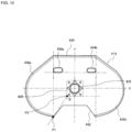
- FIG. 10 is a plan view illustrating a structure of a panel 430 of a gas rectifying member 418 used in an airbag device according to Embodiment 5 of the present invention.
- a panel 430 with an external shape different from other embodiments is employed, and a length (height) in the Y direction is relatively large. Therefore, when the airbag 16 is deployed, first and second opening portions 434b, 434a protrude further to the occupant D side than the cover 42 (see FIG. 6 ).
- FIG. 11 is a plan view illustrating a structure of a panel 530 of a gas rectifying member 518 used in an airbag device according to Embodiment 6 of the present invention.
- a lower opening portion 532 is formed in an extremely horizontally long manner, and thus the angle ⁇ is very large. Therefore, the opening area of the lower opening portion 532 formed after stitching is increased.
- FIG. 12 is a plan view illustrating a panel structure of a gas rectifying member 618 used in an airbag device according to Embodiment 7 of the present invention.
- (A) illustrates a panel 630 prior to stitching
- (B) illustrates the panel 630 in a stitched condition.
- the present embodiment is similar to Embodiment 3 illustrated in FIG. 8 , with the only difference being a stitching point 636 on an outer periphery of the panel 630.
- the stitching line 636 on an outer peripheral portion of the panel 630 is continuous and uninterrupted at the 12 o'clock position. Therefore, as illustrated in (B) of the drawing, the 12 o'clock side (upper portion) of the gas rectifying member 618 after stitching is completely closed. Furthermore, as a result, the expansion gas released from the inflator will flow out into an interior of the airbag only from a lower opening portion 632 and first and second opening portions 634b, 634a.
Claims (13)
- Lenkradeinheit, umfassend ein Lenkrad (12) eines Fahrzeugs und eine Airbagvorrichtung (10), die in dem Lenkrad (12) aufbewahrt wird, die Airbagvorrichtung umfassend:einen Gasgenerator (14), der Expansionsgas generiert;einen Airbag (16), der sich durch das Expansionsgas ausdehnt und entfaltet, um einen Insassen zu schützen; undein Gasrektifizierglied (18), das bereitgestellt ist, um die Insassenseite des Gasgenerators (14) innerhalb des Airbags (16) abzudecken, und das den Strom des Expansionsgases steuert;wobeidas Gasrektifizierglied (18) aus einer ebenen Bahn (30) ausgebildet ist, einschließlich eines Abschnitts, der beidseitig symmetrisch zu einer Linie ist, die 12 Uhr und 6 Uhr (X-Achse) verbindet, wenn eine Ebene parallel zu einem Kranz des Lenkrads als ein Zifferblatt betrachtet wird, und eine Konfiguration aufweist, in der ein unterer Öffnungsabschnitt (32) zum Ablassen des Expansionsgases in einer 6-Uhr-Richtung durch Zusammennähen eines linken und eines rechten Randabschnitts (36a, 36b) der Bahn ausgebildet wird, wobei die Insassenseite des Gasgenerators bedeckt wird, undwenn die Bahn (30) vor dem Nähen durch die X-Achse und eine Linie, die 3 Uhr und 9 Uhr (Y-Achse) gemäß einer tatsächlichen Installationsausrichtung in Bezug auf das Lenkrad (12) verbindet, praktisch in vier Teile unterteilt ist, ein erster Öffnungsabschnitt (34b) und ein zweiter Öffnungsabschnitt (34a) jeweils in einem oberen rechten Abschnitt zwischen 12 Uhr und 3 Uhr und in einem oberen linken Abschnitt zwischen 9 Uhr und 12 Uhr ausgebildet sind,dadurch gekennzeichnet, dass der untere Öffnungsabschnitt (32) als eine Kerbe in der Bahn (30) ausgebildet ist und ein Randabschnitt der Kerbe nicht genäht ist, wobei die Kerbe, die den unteren offenen Abschnitt (32) ausbildet, zu einer trapezförmigen Gestalt ausgebildet ist, in der ein Randabschnitt auf einer gegenüberliegenden Seite von der 12-Uhr-Position breiter als ein Randabschnitt auf einer näheren Seite zu der 12-Uhr-Position in einem Zustand vor dem Zusammennähen des linken und des rechten Randabschnitts (36a, 36b) der Bahn (30) ist.
- Lenkradeinheit nach Anspruch 1, wobei ein Winkel θ zwischen einer geraden Linie, die einen unteren Eckabschnitt der trapezförmigen Kerbe und das Verbindungsteil verbindet, und einer geraden Linie in einer 3-Uhr- bis 9-Uhr-Richtung 110° bis 170° beträgt.
- Lenkradeinheit nach Anspruch 2, wobei der Winkel θ 120° bis 160° beträgt.
- Lenkradeinheit nach einem der Ansprüche 1 bis 3, wobei ein oberer Öffnungsabschnitt (38) zum Ablassen des Expansionsgases in der 12-Uhr-Richtung ferner ausgebildet ist und der obere Öffnungsabschnitt (38) eine kleinere Öffnungsfläche als der untere Öffnungsabschnitt (32) aufweist.
- Lenkradeinheit nach einem der Ansprüche 1 bis 4, wobei das Gasrektifizierglied (18) und der Airbag (16) an einem Verbindungsteil in der Nähe eines Außenumfangs des Gasgenerators (14) miteinander verbunden sind.
- Lenkradeinheit nach einem der Ansprüche 1 bis 5, wobei die Fläche des ersten und des zweiten Öffnungsabschnitts (34a, 34b) kleiner als die Öffnungsfläche des unteren Öffnungsabschnitts (32) ist.
- Lenkradeinheit nach einem der Ansprüche 1 bis 6, wobei die Fläche des ersten und des zweiten Öffnungsabschnitts (3a, 34b) 840 mm2 bis 4800 mm2 beträgt.
- Lenkradeinheit nach einem der Ansprüche 1 bis 7, wobei eine Abdeckung (42), die eine Oberfläche des aufbewahrten Airbags auf der Insassenseite abdeckt, bereitgestellt ist,die Abdeckung eine Struktur aufweist, die geöffnet wird, wenn der Airbag (16) entfaltet wird, undmindestens ein Abschnitt des ersten und des zweiten Öffnungsabschnitts (34a, 34b), wenn der Airbag (16) entfaltet wird, sich an einer Position befindet, die mehr zu der Insassenseite als eine Oberfläche der Abdeckung (42) vorsteht.
- Lenkradeinheit nach einem der Ansprüche 1 bis 8, wobei eine Abdeckung (42), die eine Oberfläche des aufbewahrten Airbags (16) auf der Insassenseite abdeckt, bereitgestellt ist, die Abdeckung (42) eine Struktur aufweist, die geöffnet wird, wenn der Airbag (16) entfaltet wird, und mindestens ein Abschnitt des unteren Öffnungsabschnitts (32), wenn der Airbag (16) entfaltet wird, sich an einer Position befindet, die mehr zu der Insassenseite als eine Oberfläche der Abdeckung (42) vorsteht.
- Lenkradeinheit nach einem der Ansprüche 1 bis 9, wobei der Airbag (16) enthält: eine vordere Bahn (20), die auf der Insassenseite positioniert ist; eine hintere Bahn (22), die auf der Gasgeneratorseite positioniert ist; und eine seitliche Bahn (24), die die vordere Bahn (20) und die hintere Bahn (22) verbindet.
- Lenkradeinheit nach Anspruch 10, wobei eine Fehlausrichtung in einer Y-Achsenrichtung zwischen einer Mittelposition der vorderen Bahn (20) des Airbags (16) in einem aufbewahrten Zustand und einer Mittelposition des Gasrektifizierglieds (18) ±30 mm oder weniger beträgt, wenn die 3-Uhr- bis 9-Uhr-Richtung die Y-Achsenrichtung ist.
- Lenkradeinheit nach Anspruch 10 oder 11, wobei eine Fehlausrichtung in einer X-Achsenrichtung zwischen einer Mittelposition der vorderen Bahn (20) des Airbags in einem aufbewahrten Zustand und einer Mittelposition des Gasrektifizierglieds (18) ±30 mm oder weniger beträgt, wenn die 12-Uhr- bis 6-Uhr-Richtung die X-Achsenrichtung ist.
- Lenkradeinheit nach einem der Ansprüche 10 bis 12, wobei das Gasrektifizierglied (18) angeordnet ist, um in dem Zustand, in dem der Airbag (16) aufbewahrt ist, mit der vorderen Bahn (20) in Kontakt zu stehen.
Applications Claiming Priority (2)
| Application Number | Priority Date | Filing Date | Title |
|---|---|---|---|
| JP2019084758 | 2019-04-25 | ||
| PCT/JP2020/013132 WO2020217824A1 (ja) | 2019-04-25 | 2020-03-24 | ドライバエアバッグ装置 |
Publications (3)
| Publication Number | Publication Date |
|---|---|
| EP3960550A1 EP3960550A1 (de) | 2022-03-02 |
| EP3960550A4 EP3960550A4 (de) | 2023-01-25 |
| EP3960550B1 true EP3960550B1 (de) | 2024-03-13 |
Family
ID=72942539
Family Applications (1)
| Application Number | Title | Priority Date | Filing Date |
|---|---|---|---|
| EP20794420.8A Active EP3960550B1 (de) | 2019-04-25 | 2020-03-24 | Fahrerairbagvorrichtung |
Country Status (6)
| Country | Link |
|---|---|
| US (1) | US11752964B2 (de) |
| EP (1) | EP3960550B1 (de) |
| JP (1) | JP7291210B2 (de) |
| KR (1) | KR102609538B1 (de) |
| CN (1) | CN113677568B (de) |
| WO (1) | WO2020217824A1 (de) |
Families Citing this family (1)
| Publication number | Priority date | Publication date | Assignee | Title |
|---|---|---|---|---|
| KR20220107264A (ko) * | 2019-12-05 | 2022-08-02 | 아우토리브 디벨롭먼트 아베 | 에어백 장치 |
Family Cites Families (37)
| Publication number | Priority date | Publication date | Assignee | Title |
|---|---|---|---|---|
| JPS5216140U (de) * | 1975-07-23 | 1977-02-04 | ||
| JPH0948307A (ja) * | 1995-08-11 | 1997-02-18 | Denso Corp | エアバッグの製造方法 |
| JPH10226294A (ja) * | 1997-02-17 | 1998-08-25 | Toyo Tire & Rubber Co Ltd | 車両用エアバッグ |
| JP3577208B2 (ja) * | 1997-12-09 | 2004-10-13 | トヨタ自動車株式会社 | 助手席用エアバッグ装置 |
| JP2000085512A (ja) * | 1998-09-08 | 2000-03-28 | Denso Corp | エアバッグ・モジュール |
| DE19858690A1 (de) * | 1998-12-18 | 2000-06-21 | Delphi Automotive Systems Gmbh | Luftsack |
| JP4114303B2 (ja) * | 1999-07-15 | 2008-07-09 | タカタ株式会社 | エアバッグ、エアバッグ装置及びステアリング |
| DE10011066A1 (de) * | 2000-03-07 | 2001-09-13 | Delphi Tech Inc | Luftsackmodul |
| DE10030488A1 (de) * | 2000-06-21 | 2002-01-03 | Delphi Tech Inc | Luftsack |
| JP2003170796A (ja) * | 2001-12-06 | 2003-06-17 | Takata Corp | エアバッグ |
| CA2420745A1 (en) * | 2002-04-26 | 2003-10-26 | David E. Thomas | Front passenger airbag pocket baffle |
| JP4100129B2 (ja) * | 2002-10-28 | 2008-06-11 | タカタ株式会社 | エアバッグ装置 |
| US6926303B2 (en) | 2003-10-06 | 2005-08-09 | Trw Vehicle Safety Systems Inc. | Inflatable vehicle occupant protection device with inflation fluid deflector |
| JP2006248511A (ja) * | 2005-02-09 | 2006-09-21 | Takata Corp | エアバッグ及びエアバッグ装置 |
| JP2006297958A (ja) * | 2005-04-15 | 2006-11-02 | Takata Corp | エアバッグおよびエアバッグ装置 |
| US7445238B2 (en) * | 2005-05-06 | 2008-11-04 | Tk Holdings Inc. | Occupant protection apparatus |
| JP2009113502A (ja) * | 2006-02-09 | 2009-05-28 | Takata Corp | エアバッグ及びエアバッグ装置 |
| EP1864871B1 (de) * | 2006-06-02 | 2008-12-03 | Toyoda Gosei Co., Ltd. | Airbag-Vorrichtung |
| JP5641637B2 (ja) * | 2009-12-23 | 2014-12-17 | タカタ株式会社 | エアバッグ及びエアバッグ装置 |
| JP5206707B2 (ja) * | 2010-02-23 | 2013-06-12 | 豊田合成株式会社 | 助手席用エアバッグ装置 |
| JP5883613B2 (ja) * | 2011-10-20 | 2016-03-15 | 芦森工業株式会社 | エアバッグ装置 |
| JP5664567B2 (ja) * | 2012-01-31 | 2015-02-04 | 豊田合成株式会社 | ステアリングホイール用エアバッグ装置 |
| EP2810831B1 (de) * | 2012-02-01 | 2018-05-09 | Toyota Jidosha Kabushiki Kaisha | Seitenairbagvorrichtung für ein fahrzeug |
| JP6143542B2 (ja) * | 2013-05-13 | 2017-06-07 | 芦森工業株式会社 | エアバッグ装置 |
| JP5880489B2 (ja) * | 2013-06-25 | 2016-03-09 | トヨタ自動車株式会社 | 運転席用エアバッグ装置 |
| US9283921B2 (en) * | 2013-11-21 | 2016-03-15 | Ford Global Technologies, Llc | Driver airbag module having multiple deployment paths |
| JP6422738B2 (ja) * | 2014-10-31 | 2018-11-14 | 芦森工業株式会社 | エアバッグ装置 |
| JP6726543B2 (ja) * | 2016-07-01 | 2020-07-22 | 日本プラスト株式会社 | エアバッグ |
| JP2018020737A (ja) * | 2016-08-05 | 2018-02-08 | タカタ株式会社 | 運転席用エアバッグ、運転席用エアバッグ装置及びステアリングホイール |
| JP6806005B2 (ja) * | 2017-08-25 | 2020-12-23 | 豊田合成株式会社 | エアバッグ |
| JP6798954B2 (ja) * | 2017-09-14 | 2020-12-09 | 本田技研工業株式会社 | エアバッグ装置 |
| JP6876817B2 (ja) * | 2017-10-05 | 2021-05-26 | オートリブ ディベロップメント エービー | エアバッグ装置 |
| KR102501269B1 (ko) * | 2018-06-04 | 2023-02-17 | 아우토리브 디벨롭먼트 아베 | 차량의 운전석 에어백 장치 |
| JP7316364B2 (ja) * | 2019-09-17 | 2023-07-27 | オートリブ ディベロップメント エービー | 運転席用エアバッグ装置 |
| JP7215453B2 (ja) * | 2020-03-31 | 2023-01-31 | 豊田合成株式会社 | 運転席用エアバッグ装置 |
| US11472363B2 (en) * | 2020-04-13 | 2022-10-18 | Autoliv Development Ab | Driver's side airbag device |
| JP7400764B2 (ja) * | 2021-03-29 | 2023-12-19 | 豊田合成株式会社 | エアバッグ装置 |
-
2020
- 2020-03-24 KR KR1020217037720A patent/KR102609538B1/ko active IP Right Grant
- 2020-03-24 EP EP20794420.8A patent/EP3960550B1/de active Active
- 2020-03-24 US US17/594,580 patent/US11752964B2/en active Active
- 2020-03-24 WO PCT/JP2020/013132 patent/WO2020217824A1/ja unknown
- 2020-03-24 CN CN202080028575.8A patent/CN113677568B/zh active Active
- 2020-03-24 JP JP2021515890A patent/JP7291210B2/ja active Active
Also Published As
| Publication number | Publication date |
|---|---|
| CN113677568B (zh) | 2023-11-24 |
| US20220203920A1 (en) | 2022-06-30 |
| WO2020217824A1 (ja) | 2020-10-29 |
| EP3960550A1 (de) | 2022-03-02 |
| US11752964B2 (en) | 2023-09-12 |
| JP7291210B2 (ja) | 2023-06-14 |
| EP3960550A4 (de) | 2023-01-25 |
| KR20210153698A (ko) | 2021-12-17 |
| JPWO2020217824A1 (de) | 2020-10-29 |
| CN113677568A (zh) | 2021-11-19 |
| KR102609538B1 (ko) | 2023-12-04 |
Similar Documents
| Publication | Publication Date | Title |
|---|---|---|
| EP2953821B1 (de) | Airbag mit geschlitzter entlüftung | |
| US9403504B2 (en) | Airbag and airbag device | |
| US8240706B2 (en) | Airbag arranged on the vehicle roof | |
| US7578518B2 (en) | Occupant protection device | |
| EP1992526B1 (de) | Verfahren zur Montage eines Haltegurts für eine Airbag-Vorrichtung und Airbag-Vorrichtung | |
| US8141897B2 (en) | Guide plate for side air bag | |
| US20130001934A1 (en) | Occupant protection device | |
| WO2010026970A1 (ja) | 車両用ニーエアバッグ装置 | |
| US11235731B2 (en) | Airbag device | |
| JP6790858B2 (ja) | 運転席用エアバッグ及び運転席用エアバッグ装置 | |
| US9333937B1 (en) | Airbag cover with stress relief features | |
| US11332096B2 (en) | Knee airbag device | |
| EP3960550B1 (de) | Fahrerairbagvorrichtung | |
| JPH06321044A (ja) | エアバッグ装置の弾性カバー | |
| US20070057498A1 (en) | Airbag device | |
| US10479316B2 (en) | Airbag apparatus for vehicle | |
| US20240149822A1 (en) | Airbag Attachment Structure | |
| US11618407B2 (en) | Side airbag for vehicle | |
| JP6754347B2 (ja) | エアバッグ装置 | |
| JPH11348713A (ja) | 車両用エアバッグ | |
| JP2006273244A (ja) | 運転席用エアバッグ装置 | |
| EP1602533B1 (de) | Airbagvorrichtung und Herstellungsverfahren für Airbagvorrichtung | |
| JPH09295546A (ja) | 運転席用エアバッグモジュール | |
| US20240010157A1 (en) | Airbag device | |
| US11858454B2 (en) | Tether design for airbag assemblies |
Legal Events
| Date | Code | Title | Description |
|---|---|---|---|
| STAA | Information on the status of an ep patent application or granted ep patent |
Free format text: STATUS: THE INTERNATIONAL PUBLICATION HAS BEEN MADE |
|
| PUAI | Public reference made under article 153(3) epc to a published international application that has entered the european phase |
Free format text: ORIGINAL CODE: 0009012 |
|
| STAA | Information on the status of an ep patent application or granted ep patent |
Free format text: STATUS: REQUEST FOR EXAMINATION WAS MADE |
|
| 17P | Request for examination filed |
Effective date: 20211116 |
|
| AK | Designated contracting states |
Kind code of ref document: A1 Designated state(s): AL AT BE BG CH CY CZ DE DK EE ES FI FR GB GR HR HU IE IS IT LI LT LU LV MC MK MT NL NO PL PT RO RS SE SI SK SM TR |
|
| DAV | Request for validation of the european patent (deleted) | ||
| DAX | Request for extension of the european patent (deleted) | ||
| A4 | Supplementary search report drawn up and despatched |
Effective date: 20230103 |
|
| RIC1 | Information provided on ipc code assigned before grant |
Ipc: B60R 21/2346 20110101ALI20221221BHEP Ipc: B60R 21/203 20060101AFI20221221BHEP |
|
| GRAP | Despatch of communication of intention to grant a patent |
Free format text: ORIGINAL CODE: EPIDOSNIGR1 |
|
| STAA | Information on the status of an ep patent application or granted ep patent |
Free format text: STATUS: GRANT OF PATENT IS INTENDED |
|
| INTG | Intention to grant announced |
Effective date: 20231002 |
|
| GRAS | Grant fee paid |
Free format text: ORIGINAL CODE: EPIDOSNIGR3 |
|
| GRAA | (expected) grant |
Free format text: ORIGINAL CODE: 0009210 |
|
| STAA | Information on the status of an ep patent application or granted ep patent |
Free format text: STATUS: THE PATENT HAS BEEN GRANTED |
|
| AK | Designated contracting states |
Kind code of ref document: B1 Designated state(s): AL AT BE BG CH CY CZ DE DK EE ES FI FR GB GR HR HU IE IS IT LI LT LU LV MC MK MT NL NO PL PT RO RS SE SI SK SM TR |
|
| REG | Reference to a national code |
Ref country code: GB Ref legal event code: FG4D |
|
| REG | Reference to a national code |
Ref country code: CH Ref legal event code: EP |
|
| REG | Reference to a national code |
Ref country code: DE Ref legal event code: R096 Ref document number: 602020027275 Country of ref document: DE |
|
| PGFP | Annual fee paid to national office [announced via postgrant information from national office to epo] |
Ref country code: DE Payment date: 20240328 Year of fee payment: 5 Ref country code: GB Payment date: 20240319 Year of fee payment: 5 |