EP3957979B1 - Sample analyzing apparatus - Google Patents
Sample analyzing apparatus Download PDFInfo
- Publication number
- EP3957979B1 EP3957979B1 EP20805409.8A EP20805409A EP3957979B1 EP 3957979 B1 EP3957979 B1 EP 3957979B1 EP 20805409 A EP20805409 A EP 20805409A EP 3957979 B1 EP3957979 B1 EP 3957979B1
- Authority
- EP
- European Patent Office
- Prior art keywords
- gas
- sample
- component
- signal
- concentration
- Prior art date
- Legal status (The legal status is an assumption and is not a legal conclusion. Google has not performed a legal analysis and makes no representation as to the accuracy of the status listed.)
- Active
Links
Images


Classifications
-
- G—PHYSICS
- G01—MEASURING; TESTING
- G01N—INVESTIGATING OR ANALYSING MATERIALS BY DETERMINING THEIR CHEMICAL OR PHYSICAL PROPERTIES
- G01N21/00—Investigating or analysing materials by the use of optical means, i.e. using sub-millimetre waves, infrared, visible or ultraviolet light
- G01N21/17—Systems in which incident light is modified in accordance with the properties of the material investigated
- G01N21/25—Colour; Spectral properties, i.e. comparison of effect of material on the light at two or more different wavelengths or wavelength bands
- G01N21/31—Investigating relative effect of material at wavelengths characteristic of specific elements or molecules, e.g. atomic absorption spectrometry
- G01N21/39—Investigating relative effect of material at wavelengths characteristic of specific elements or molecules, e.g. atomic absorption spectrometry using tunable lasers
-
- G—PHYSICS
- G01—MEASURING; TESTING
- G01J—MEASUREMENT OF INTENSITY, VELOCITY, SPECTRAL CONTENT, POLARISATION, PHASE OR PULSE CHARACTERISTICS OF INFRARED, VISIBLE OR ULTRAVIOLET LIGHT; COLORIMETRY; RADIATION PYROMETRY
- G01J3/00—Spectrometry; Spectrophotometry; Monochromators; Measuring colours
- G01J3/02—Details
- G01J3/10—Arrangements of light sources specially adapted for spectrometry or colorimetry
-
- G—PHYSICS
- G01—MEASURING; TESTING
- G01J—MEASUREMENT OF INTENSITY, VELOCITY, SPECTRAL CONTENT, POLARISATION, PHASE OR PULSE CHARACTERISTICS OF INFRARED, VISIBLE OR ULTRAVIOLET LIGHT; COLORIMETRY; RADIATION PYROMETRY
- G01J3/00—Spectrometry; Spectrophotometry; Monochromators; Measuring colours
- G01J3/28—Investigating the spectrum
- G01J3/42—Absorption spectrometry; Double beam spectrometry; Flicker spectrometry; Reflection spectrometry
- G01J3/433—Modulation spectrometry; Derivative spectrometry
- G01J3/4338—Frequency modulated spectrometry
-
- G—PHYSICS
- G01—MEASURING; TESTING
- G01N—INVESTIGATING OR ANALYSING MATERIALS BY DETERMINING THEIR CHEMICAL OR PHYSICAL PROPERTIES
- G01N21/00—Investigating or analysing materials by the use of optical means, i.e. using sub-millimetre waves, infrared, visible or ultraviolet light
- G01N21/01—Arrangements or apparatus for facilitating the optical investigation
-
- G—PHYSICS
- G01—MEASURING; TESTING
- G01N—INVESTIGATING OR ANALYSING MATERIALS BY DETERMINING THEIR CHEMICAL OR PHYSICAL PROPERTIES
- G01N21/00—Investigating or analysing materials by the use of optical means, i.e. using sub-millimetre waves, infrared, visible or ultraviolet light
- G01N21/17—Systems in which incident light is modified in accordance with the properties of the material investigated
- G01N21/25—Colour; Spectral properties, i.e. comparison of effect of material on the light at two or more different wavelengths or wavelength bands
- G01N21/27—Colour; Spectral properties, i.e. comparison of effect of material on the light at two or more different wavelengths or wavelength bands using photo-electric detection ; circuits for computing concentration
- G01N21/274—Calibration, base line adjustment, drift correction
-
- G—PHYSICS
- G01—MEASURING; TESTING
- G01N—INVESTIGATING OR ANALYSING MATERIALS BY DETERMINING THEIR CHEMICAL OR PHYSICAL PROPERTIES
- G01N21/00—Investigating or analysing materials by the use of optical means, i.e. using sub-millimetre waves, infrared, visible or ultraviolet light
- G01N21/17—Systems in which incident light is modified in accordance with the properties of the material investigated
- G01N21/25—Colour; Spectral properties, i.e. comparison of effect of material on the light at two or more different wavelengths or wavelength bands
- G01N21/31—Investigating relative effect of material at wavelengths characteristic of specific elements or molecules, e.g. atomic absorption spectrometry
- G01N21/35—Investigating relative effect of material at wavelengths characteristic of specific elements or molecules, e.g. atomic absorption spectrometry using infrared light
- G01N21/3504—Investigating relative effect of material at wavelengths characteristic of specific elements or molecules, e.g. atomic absorption spectrometry using infrared light for analysing gases, e.g. multi-gas analysis
-
- G—PHYSICS
- G01—MEASURING; TESTING
- G01N—INVESTIGATING OR ANALYSING MATERIALS BY DETERMINING THEIR CHEMICAL OR PHYSICAL PROPERTIES
- G01N1/00—Sampling; Preparing specimens for investigation
- G01N1/28—Preparing specimens for investigation including physical details of (bio-)chemical methods covered elsewhere, e.g. G01N33/50, C12Q
- G01N1/44—Sample treatment involving radiation, e.g. heat
-
- G—PHYSICS
- G01—MEASURING; TESTING
- G01N—INVESTIGATING OR ANALYSING MATERIALS BY DETERMINING THEIR CHEMICAL OR PHYSICAL PROPERTIES
- G01N21/00—Investigating or analysing materials by the use of optical means, i.e. using sub-millimetre waves, infrared, visible or ultraviolet light
- G01N21/17—Systems in which incident light is modified in accordance with the properties of the material investigated
- G01N21/25—Colour; Spectral properties, i.e. comparison of effect of material on the light at two or more different wavelengths or wavelength bands
- G01N21/31—Investigating relative effect of material at wavelengths characteristic of specific elements or molecules, e.g. atomic absorption spectrometry
- G01N2021/3129—Determining multicomponents by multiwavelength light
-
- G—PHYSICS
- G01—MEASURING; TESTING
- G01N—INVESTIGATING OR ANALYSING MATERIALS BY DETERMINING THEIR CHEMICAL OR PHYSICAL PROPERTIES
- G01N21/00—Investigating or analysing materials by the use of optical means, i.e. using sub-millimetre waves, infrared, visible or ultraviolet light
- G01N21/17—Systems in which incident light is modified in accordance with the properties of the material investigated
- G01N21/25—Colour; Spectral properties, i.e. comparison of effect of material on the light at two or more different wavelengths or wavelength bands
- G01N21/31—Investigating relative effect of material at wavelengths characteristic of specific elements or molecules, e.g. atomic absorption spectrometry
- G01N21/35—Investigating relative effect of material at wavelengths characteristic of specific elements or molecules, e.g. atomic absorption spectrometry using infrared light
- G01N21/3504—Investigating relative effect of material at wavelengths characteristic of specific elements or molecules, e.g. atomic absorption spectrometry using infrared light for analysing gases, e.g. multi-gas analysis
- G01N21/3518—Devices using gas filter correlation techniques; Devices using gas pressure modulation techniques
Definitions
- the present invention relates to a solid sample analyzing apparatus for analyzing a component to be measured contained in a sample.
- the laser light source emits a modulated light whose wavelength is modulated at a predetermined modulation frequency.
- WMS wavelength modulation spectroscopy method
- the wavelength modulation method calculates the concentration of the component to be measured by calculating the representative value that depends on the concentration of the component to be measured from the intensity related signal relating to the intensity of the sample light and using the representative value, it is possible to reliably analyze the component to be measured contained in the solid sample while spectral calculation processing for concentration quantification, which is necessary in conventional WMS, is made unnecessary.
- the ultraviolet fluorescence method is not used, there is no need of using an ultraviolet light source, and maintenance such as frequent replacement of the ultraviolet light source can be eliminated.
- the first calculation section calculates a sample correlation value, which is a correlation value between the intensity related signal and the characteristic signal, as the representative value
- the second calculation section calculates the concentration of the component to be measured by using the sample correlation value.
- calculating the correlation value includes taking the inner product of the intensity related signal and the characteristic signal as well as taking the correlation between the intensity related signal and the characteristic signal.
- the plurality of the components to be measured are at least one of CO 2 , CO, SO 2 , H 2 O, and NO X .
- the sample analyzing apparatus of the present claimed invention further comprises an analyzer (NDIR analyzer) using a non-dispersive infrared absorption method in addition to the gas analysis section.
- an analyzer NDIR analyzer
- NDIR analyzer a non-dispersive infrared absorption method
- the sample analyzing apparatus 100 combusts the solid sample (W) in an oxygen stream and analyzes a component to be measured contained in the gas generated by the combustion by using the infrared absorption method.
- the sample analyzing apparatus 100 comprises a heating furnace 2 that heats a container (R) that holds and burns the solid sample (W), and a gas analysis section 3 that analyzes the component to be measured contained in the gas generated by the combustion of the solid sample (W).
- the container (R) of this embodiment which is a sample holding body, is called a crucible made of magnetic materials such as ceramics.
- the correlation value calculation section 162 uses a function that is easier to capture waveform features of the logarithmic intensity L(t) than a sine function as the plurality of the characteristic signals F i (t).
- the sample gas containing the component to be measured for example, SO 2
- one interference component for example, H 2 O
- the storage section 163 stores the alone correlation value, which is a value obtained by subtracting the reference correlation value from the correlation value in case that the component to be measured and each of the interference components exist alone and the value is calibrated by converting into per unit concentration. This eliminates the offset contained in the alone correlation value so that the alone correlation value is made to be proportional to the concentration of the component to be measured and the interference components so that it is possible to reduce measurement errors.
- the arrangement may be so not to subtract the reference correlation value.
- the concentration calculation section 164 calculates the concentration of the component to be measured by using the plurality of the sample correlation values obtained by the correlation value calculation section 162.
- the light source control section 15 controls the semiconductor laser 12 to modulate the wavelength of the laser light both at the modulation frequency and around the peak of the absorption spectrum of the component to be measured.
- the reference measurement using the zero gas may be conducted to measure the reference correlation value.
- the correlation values S 1i and S 2i of the interference components are calculated by the correlation value calculation section 162 by introducing the span gas in which the interference component exists alone into the cell 1(refer to Fig. 6 ).
- S 1i is the correlation value to the first characteristic signal
- S 2i is the correlation value to the second characteristic signal.
- the correlation value calculation section 162 calculates the alone correlation values s 1i and s 2i by dividing a value that is obtained by subtracting the reference correlation value from those correlation values S 1i and S 2i by the span gas concentration c i of the interference component.
- the span gas concentration of the interference component c i is input to the signal processing unit 16 in advance by a user or the like.
- the alone correlation values s 1t , s 2t , s 1i , s 2i calculated as described above are stored in the storage section 163.
- the reference measurement may be performed before the product is shipped or may be performed periodically.
- the light source control section 15 controls the semiconductor laser 12 and modulates the wavelength of the laser light both at the modulation frequency and around the peak of the absorption spectrum of the component to be measured.
- the concentration calculation section 164 solves following simultaneous equations with two unknown numbers comprising the sample correlation values S 1 ', S 2 ' calculated by the correlation value calculation section 162, the alone correlation values s 1t , s 2t , s 1i , s 2i of the storage section 163, and each of the concentrations C tar , C int of the component to be measured and each of the interference components respectively.
- this embodiment a difference in an analysis accuracy of SO 2 concentration between the sample analyzing apparatus 100 using the gas analysis section 3 of this embodiment (hereinafter also referred to as “this embodiment") and a metal analysis unit using a conventional NDIR analyzer (hereinafter also referred to as the "NDIR”) will be explained.
- a dehumidifier is arranged in an upstream side of the NDIR analyzer.
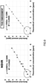
- Fig. 8 shows the peak waveforms detected by the NDIR and this embodiment when the SO 2 concentration is 0.48 ppm.
- the signal-to-noise by the NDIR is 1.3, while the signal-to-noise by this embodiment is 35.9.
- the signal-to-noise ratio is about 27 times higher than that of the NDIR.
- the gas analysis section 3 comprises the laser light source 12 that irradiates the gas with the laser light and the photodetector 13 that detects the intensity of the sample light as being the laser light that has transmitted through the gas
- the gas analysis section 3 comprises the laser light source 12 that irradiates the gas with the laser light and the photodetector 13 that detects the intensity of the sample light as being the laser light that has transmitted through the gas
- the laser light source 12 since the laser light source 12 is used, the maintenance frequency can be reduced.
- the wavelength modulation spectroscopy (WMS) that uses the intensity related signals obtained by emitting the modulated light modulated at a predetermined modulation frequency calculates the representative value that depends on the concentration of the component to be measured from the intensity related signal relating to the intensity of the sample light, and calculates the concentration of the component to be measured by using the representative value, it is possible to reliably analyze the component to be measured contained in the solid sample (W), while eliminating the need for spectral calculation processing for concentration quantification, which is necessary in a conventional WMS.
- WMS wavelength modulation spectroscopy
- the concentration can be calculated with the same accuracy using at most a few to several dozen correlation values.
- the load of arithmetic processing can be dramatically reduced, and an advanced arithmetic processing unit is no longer necessary, which reduces the cost and downsized the sample analyzing apparatus 100.
- the sample analyzing apparatus 100 of this embodiment does not use the ultraviolet fluorescence method, there is no need of using a UV light source, and the maintenance of frequent replacement of the UV light source can be eliminated.
- the sample analyzing apparatus 100 of the second embodiment differs from the above-mentioned first embodiment in the arrangement of the signal processing unit 14.
- the other arrangement is the same as that of the first embodiment, and an explanation is omitted in the following.
- the cell 11 in order to make the optical absorption practically zero, the cell 11 is enclosed with a zero gas, for example, N 2 gas, which makes the optical absorption practically zero in the wavelength band where the optical absorption of the component to be measured is observed, however, other gas may be enclosed or inside of the cell 11 may be vacuumed.
- a zero gas for example, N 2 gas, which makes the optical absorption practically zero in the wavelength band where the optical absorption of the component to be measured is observed, however, other gas may be enclosed or inside of the cell 11 may be vacuumed.
- the output signal is received from the photodetector 13 in a state that the zero gas is enclosed in the cell 11, and the value of the output signal is stored in the measurement result data storage section.
- the value of the output signal received from the photodetector 13 in this reference measurement namely, the reference light intensity, is shown in a time series graph in Fig. 12(a) . More specifically, only the change in the optical output due to the modulation of the driving current (voltage) of the laser is expressed in the output signal of the photodetector 13.
- the concentration indication value which is determined based on the value of the frequency component twice the modulation frequency, will not be influenced.
- the above is an example of the operation of the sample analyzing apparatus 100 in case that the sample gas does not contain any interference components other than the component to be measured.
- the absorbance signal value A(t) is expressed by the following equation (expression 9) due to the linearity of each of the absorbance.
- the sample analyzing apparatus 100 operates based on the above-described principle.
- the sample analyzing apparatus 100 in this embodiment stores the frequency components a 1m , a 2m , a 1i , a 2i of the respective absorbance signals in a predetermined area of the memory in case that the component to be measured and the interference component exist alone, for example, by flowing the span gas in advance and previously measuring the frequency components a 1m , a 2m , a 1i , a 2i .
- the frequency components a 1m , a 2m , a 1i , and a 2i are obtained and stored by measuring the light intensity to be measured and the reference light intensity for each of the components to be measured and the interference component, by calculating their intensity ratio logarithm (the absorbance signal), and then by obtaining the frequency components a 1m , a2m, a 1i , and a 2i from this intensity ratio logarithm by lock-in detection.
- the absorbance signals per unit concentration A m (t) and A i (t) may be stored instead of the above-mentioned frequency components, and the frequency components a 1m , a 2m , a 1i , a 2i may be calculated from the above equations (expression 7 and expression 8).
- the sample analyzing apparatus 100 specifies the component to be measured and the interference component by the input from the operator or other means.
- the concentration calculation section 168 calculates the concentration (or concentration indication value) C m , which indicates the concentration of the gas to be measured with the interference influence removed, by applying the values of the lock-in data a 1 and a 2 and the values of the frequency components a 1m , a 2m , a 1i , and a 2i stored in the memory to the above equation (expression 10), or by conducting a calculation equal to it.
- the concentration (or concentration indication) C i of each of the interference components (or concentration indicating values) may be calculated.
- the concentration of the component to be measured, from which the interference influence has been removed can be determined in the same way by adding higher order frequency components as many as the number of interference components, and solving simultaneous equations with the same number of elements as the number of component types.
- the plurality of the characteristic signals are not limited to the above-mentioned first embodiment, and it may be functions that differ from each other.
- a function indicating the light intensity, the logarithmic intensity or the waveform (actual measurement spectrum) of the absorbance obtained by flowing a span gas whose concentration is known may be used as the characteristic signal. In case of measuring the concentration of one component to be measured, at least one characteristic signal will do.
- the gas analysis section 3 may comprise a plurality of the semiconductor lasers 12 as the light source to irradiate the cell 11 with the laser light, as shown in Fig. 15 .
- the signal processing unit 14, as shown in Fig. 16 produces functions as the light source control section 15 that controls the output of the semiconductor lasers 12, the signal separation section 17 that separates the signal of each of the semiconductor lasers 12 from the light intensity signal obtained by the photodetector 13, and the signal processing section 16 that receives the signals of each of the semiconductor lasers separated by the signal separation section 17 and that calculates the concentration of the component to be measured by processing the values of the received signals.
- the light source control section 15 causes each of the plurality of the semiconductor lasers 12 to pulse oscillate and modulates the oscillation wavelength of the laser light at a predetermined frequency.
- the light source control section 15 controls the plurality of the semiconductor lasers 12 so that each of the semiconductor lasers 12 has an oscillation wavelength corresponding to each of the components to be measured which differ each other and the semiconductor lasers 12 pulse oscillate with the same oscillation cycle as each other and the oscillation timing differing from each other.
- the light source control section 15 sweeps the oscillation wavelength of the laser light by generating a temperature change by changing the driving current (or driving voltage) of the current source (or voltage source) at a predetermined frequency.
- the oscillation wavelength of the laser light in each of the semiconductor lasers is modulated around the peak of the optical absorption spectrum of the component to be measured.
- the modulation signal that modulates the driving current changes in a form of a triangular wave, a saw wave or a sine wave, and the frequency of the modulation signal is, for example, 100 Hz to 10 kHz.
- Figure 13 shows an example of the modulation signal changing in the triangular wave form.
- the light source control section 15 controls the plurality of semiconductor lasers 12 to pulse oscillate at different timings from each other.
- the plurality of semiconductor lasers 12 sequentially pulse oscillate, and one pulse of the other semiconductor laser 12 is included within one cycle of the pulse oscillation in one semiconductor laser 12.
- one pulse of the other semiconductor laser 12 is included in the mutually adjacent pulse of one semiconductor laser 12.
- the pulses of the plurality of semiconductor lasers 12 are oscillated so as not to overlap each other.
- the signal separation section 17 separates the signal of each of the plurality of the semiconductor lasers 12 from the light intensity signal obtained by the photodetector 13.
- the signal separation section 17 of this embodiment has a plurality of sample hold circuits that are provided corresponding to each of the plurality of the semiconductor lasers 12 and an AD converter that digitally converts the light intensity signal separated by the sample hold circuits.
- the sample hold circuits and the AD converter may be one that is common to the plurality of the semiconductor lasers 12.
- the signal processing section 16 calculates the concentration of the component to be measured corresponding to each of the semiconductor lasers 12 by using the absorption signals of each of the semiconductor lasers 12 separated by the signal separation section 17.
- the calculation of the concentration of the component to be measured by the signal processing section 16 is the same as that in the above embodiment.
Landscapes
- Physics & Mathematics (AREA)
- Spectroscopy & Molecular Physics (AREA)
- General Physics & Mathematics (AREA)
- Chemical & Material Sciences (AREA)
- Life Sciences & Earth Sciences (AREA)
- Analytical Chemistry (AREA)
- Biochemistry (AREA)
- General Health & Medical Sciences (AREA)
- Health & Medical Sciences (AREA)
- Immunology (AREA)
- Pathology (AREA)
- Optics & Photonics (AREA)
- Engineering & Computer Science (AREA)
- Mathematical Physics (AREA)
- Theoretical Computer Science (AREA)
- Investigating Or Analysing Materials By Optical Means (AREA)
Applications Claiming Priority (2)
| Application Number | Priority Date | Filing Date | Title |
|---|---|---|---|
| JP2019092441 | 2019-05-15 | ||
| PCT/JP2020/018928 WO2020230775A1 (ja) | 2019-05-15 | 2020-05-12 | 試料分析装置 |
Publications (3)
| Publication Number | Publication Date |
|---|---|
| EP3957979A1 EP3957979A1 (en) | 2022-02-23 |
| EP3957979A4 EP3957979A4 (en) | 2023-01-11 |
| EP3957979B1 true EP3957979B1 (en) | 2025-04-16 |
Family
ID=73289441
Family Applications (1)
| Application Number | Title | Priority Date | Filing Date |
|---|---|---|---|
| EP20805409.8A Active EP3957979B1 (en) | 2019-05-15 | 2020-05-12 | Sample analyzing apparatus |
Country Status (5)
| Country | Link |
|---|---|
| US (1) | US12111254B2 (https=) |
| EP (1) | EP3957979B1 (https=) |
| JP (1) | JP7461937B2 (https=) |
| CN (1) | CN113811758A (https=) |
| WO (1) | WO2020230775A1 (https=) |
Families Citing this family (2)
| Publication number | Priority date | Publication date | Assignee | Title |
|---|---|---|---|---|
| CN116148309B (zh) * | 2023-04-20 | 2023-08-15 | 钢研纳克检测技术股份有限公司 | 一种基于热导-红外法多组合的氧氮氢联测装置及方法 |
| CN117007545A (zh) * | 2023-08-11 | 2023-11-07 | 内蒙古科技大学 | 锅炉烟道尾气co2浓度红外吸收检测模型及其构建方法 |
Citations (3)
| Publication number | Priority date | Publication date | Assignee | Title |
|---|---|---|---|---|
| JPH06265475A (ja) * | 1993-03-13 | 1994-09-22 | Horiba Ltd | 酸素気流中燃焼ガス分析装置 |
| US20030082816A1 (en) * | 2001-10-26 | 2003-05-01 | Carlos Guerra | Inert gas fusion analyzer |
| EP2118638B1 (en) * | 2007-02-26 | 2013-05-22 | Yokogawa Corporation of America | Combustion gas analysis |
Family Cites Families (27)
| Publication number | Priority date | Publication date | Assignee | Title |
|---|---|---|---|---|
| DE4216508A1 (de) | 1992-05-19 | 1993-11-25 | Ortwin Dr Brandt | Feststoffanalysengerät (Vorrichtung und Verfahren) |
| US5984998A (en) | 1997-11-14 | 1999-11-16 | American Iron And Steel Institute | Method and apparatus for off-gas composition sensing |
| US6326620B1 (en) | 1999-05-07 | 2001-12-04 | Leco Corporation | Switched mode NDIR system |
| EP1409992A2 (en) | 2000-06-26 | 2004-04-21 | Murray Thomson | Method and apparatus for improved process control in combustion applications |
| US20020152797A1 (en) * | 2001-01-09 | 2002-10-24 | Mcandrew James J.F. | Gas delivery apparatus and method for monitoring a gas phase species therein |
| JP3762729B2 (ja) * | 2002-09-11 | 2006-04-05 | 株式会社堀場製作所 | 多成分分析装置 |
| EP1750116B1 (en) * | 2005-08-04 | 2013-04-17 | Axetris AG | Gas concentration detection method and device |
| JP5170034B2 (ja) * | 2009-08-24 | 2013-03-27 | 株式会社島津製作所 | ガス分析装置 |
| JP4840516B2 (ja) * | 2010-02-18 | 2011-12-21 | Jfeスチール株式会社 | 金属試料中の硫黄の分析方法および分析装置 |
| JP5370248B2 (ja) | 2010-04-07 | 2013-12-18 | 株式会社島津製作所 | ガス分析装置 |
| JP5667912B2 (ja) | 2010-05-18 | 2015-02-12 | 株式会社堀場製作所 | 吸着性ガス分析装置 |
| JP5985465B2 (ja) | 2011-03-09 | 2016-09-06 | 株式会社堀場製作所 | ガス分析装置 |
| JP2013050403A (ja) * | 2011-08-31 | 2013-03-14 | Shimadzu Corp | ガス分析装置 |
| JP5933972B2 (ja) | 2011-12-27 | 2016-06-15 | 株式会社堀場製作所 | ガス計測装置およびガス計測装置における波長変調幅の設定方法。 |
| EP3051287B1 (en) | 2013-09-25 | 2020-08-05 | Horiba, Ltd.g | Analysis device and analysis method |
| CN104316480B (zh) * | 2014-11-06 | 2016-08-24 | 中国科学院合肥物质科学研究院 | 一种含砷金精矿焙烧炉内氧气浓度的激光原位检测系统 |
| EP3312587A4 (en) * | 2015-06-22 | 2018-12-05 | Kyoto University | Ndir gas sensor, gas analyzer, photosynthesis rate measuring apparatus, and photosynthesis rate measuring method |
| JP6651126B2 (ja) * | 2015-09-08 | 2020-02-19 | 富士電機株式会社 | ガス分析計 |
| GB2544507B (en) * | 2015-11-18 | 2017-11-22 | Servomex Group Ltd | Method and system for reduction of influence of baseline distortion in absorption spectroscopy measurements |
| JP6513762B2 (ja) * | 2016-12-15 | 2019-05-15 | 株式会社堀場製作所 | 分析装置、分析装置用プログラム及び分析方法 |
| NO345903B1 (en) * | 2017-06-16 | 2021-10-04 | Neo Monitors As | Chemical analysis method for measurement of tetrafluoromethane, cf4, with improved selectivity |
| JP6907785B2 (ja) * | 2017-07-28 | 2021-07-21 | 富士電機株式会社 | ガス分析装置 |
| CN109596538B (zh) * | 2017-10-03 | 2023-08-25 | 株式会社堀场制作所 | 分析装置和分析方法 |
| JP7075862B2 (ja) * | 2017-10-16 | 2022-05-26 | 株式会社堀場製作所 | 分析装置 |
| CN108458984A (zh) | 2018-05-21 | 2018-08-28 | 郑州力创光电技术有限公司 | 基于光电传感原理的气体绝缘设备在线气体监测控制系统 |
| CN109490250B (zh) * | 2018-11-22 | 2021-06-25 | 宁波海尔欣光电科技有限公司 | 校准激光器的波长的方法及装置、气体浓度分析仪 |
| JP6886507B2 (ja) * | 2018-12-26 | 2021-06-16 | 株式会社堀場製作所 | 分析装置、分析装置用プログラム及び分析方法 |
-
2020
- 2020-05-12 EP EP20805409.8A patent/EP3957979B1/en active Active
- 2020-05-12 WO PCT/JP2020/018928 patent/WO2020230775A1/ja not_active Ceased
- 2020-05-12 JP JP2021519434A patent/JP7461937B2/ja active Active
- 2020-05-12 US US17/611,471 patent/US12111254B2/en active Active
- 2020-05-12 CN CN202080034715.2A patent/CN113811758A/zh active Pending
Patent Citations (3)
| Publication number | Priority date | Publication date | Assignee | Title |
|---|---|---|---|---|
| JPH06265475A (ja) * | 1993-03-13 | 1994-09-22 | Horiba Ltd | 酸素気流中燃焼ガス分析装置 |
| US20030082816A1 (en) * | 2001-10-26 | 2003-05-01 | Carlos Guerra | Inert gas fusion analyzer |
| EP2118638B1 (en) * | 2007-02-26 | 2013-05-22 | Yokogawa Corporation of America | Combustion gas analysis |
Also Published As
| Publication number | Publication date |
|---|---|
| EP3957979A1 (en) | 2022-02-23 |
| CN113811758A (zh) | 2021-12-17 |
| US12111254B2 (en) | 2024-10-08 |
| JPWO2020230775A1 (https=) | 2020-11-19 |
| US20220244176A1 (en) | 2022-08-04 |
| WO2020230775A1 (ja) | 2020-11-19 |
| EP3957979A4 (en) | 2023-01-11 |
| JP7461937B2 (ja) | 2024-04-04 |
Similar Documents
| Publication | Publication Date | Title |
|---|---|---|
| EP3336522B1 (en) | Analysis apparatus, non-transitory computer readable medium for analysis apparatus, and analysis method | |
| EP3218695B1 (en) | Target analyte detection and quantification in sample gases with complex background compositions | |
| CN109596538B (zh) | 分析装置和分析方法 | |
| JP6886507B2 (ja) | 分析装置、分析装置用プログラム及び分析方法 | |
| CN102027344A (zh) | 红外分光计 | |
| EP3957979B1 (en) | Sample analyzing apparatus | |
| EP4160189B1 (en) | Analysis device, program for analysis device, and analysis method | |
| EP3992614B1 (en) | Analysis device | |
| EP4439049A1 (en) | Analysis device and analysis method | |
| EP4524549A1 (en) | Infrared gas analyzer, and infrared gas analysis method | |
| EP4439048A1 (en) | Analysis device, program for analysis device, and analysis method | |
| CN118176413A (zh) | 分析装置、分析装置用程序以及分析方法 | |
| EP4446728A1 (en) | Analysis device and analysis method | |
| JP6028889B2 (ja) | レーザ式ガス分析計 |
Legal Events
| Date | Code | Title | Description |
|---|---|---|---|
| STAA | Information on the status of an ep patent application or granted ep patent |
Free format text: STATUS: THE INTERNATIONAL PUBLICATION HAS BEEN MADE |
|
| PUAI | Public reference made under article 153(3) epc to a published international application that has entered the european phase |
Free format text: ORIGINAL CODE: 0009012 |
|
| STAA | Information on the status of an ep patent application or granted ep patent |
Free format text: STATUS: REQUEST FOR EXAMINATION WAS MADE |
|
| 17P | Request for examination filed |
Effective date: 20211118 |
|
| AK | Designated contracting states |
Kind code of ref document: A1 Designated state(s): AL AT BE BG CH CY CZ DE DK EE ES FI FR GB GR HR HU IE IS IT LI LT LU LV MC MK MT NL NO PL PT RO RS SE SI SK SM TR |
|
| DAV | Request for validation of the european patent (deleted) | ||
| DAX | Request for extension of the european patent (deleted) | ||
| A4 | Supplementary search report drawn up and despatched |
Effective date: 20221214 |
|
| RIC1 | Information provided on ipc code assigned before grant |
Ipc: G01N 1/44 20060101ALI20221208BHEP Ipc: G01J 3/433 20060101ALI20221208BHEP Ipc: G01N 21/01 20060101ALI20221208BHEP Ipc: G01N 21/31 20060101ALI20221208BHEP Ipc: G01N 21/27 20060101ALI20221208BHEP Ipc: G01N 21/39 20060101ALI20221208BHEP Ipc: G01N 21/3504 20140101AFI20221208BHEP |
|
| P01 | Opt-out of the competence of the unified patent court (upc) registered |
Effective date: 20231108 |
|
| STAA | Information on the status of an ep patent application or granted ep patent |
Free format text: STATUS: EXAMINATION IS IN PROGRESS |
|
| 17Q | First examination report despatched |
Effective date: 20240208 |
|
| GRAP | Despatch of communication of intention to grant a patent |
Free format text: ORIGINAL CODE: EPIDOSNIGR1 |
|
| STAA | Information on the status of an ep patent application or granted ep patent |
Free format text: STATUS: GRANT OF PATENT IS INTENDED |
|
| RIC1 | Information provided on ipc code assigned before grant |
Ipc: G01J 3/10 20060101ALI20241120BHEP Ipc: G01N 1/44 20060101ALI20241120BHEP Ipc: G01J 3/433 20060101ALI20241120BHEP Ipc: G01N 21/01 20060101ALI20241120BHEP Ipc: G01N 21/31 20060101ALI20241120BHEP Ipc: G01N 21/27 20060101ALI20241120BHEP Ipc: G01N 21/39 20060101ALI20241120BHEP Ipc: G01N 21/3504 20140101AFI20241120BHEP |
|
| INTG | Intention to grant announced |
Effective date: 20241209 |
|
| GRAS | Grant fee paid |
Free format text: ORIGINAL CODE: EPIDOSNIGR3 |
|
| GRAA | (expected) grant |
Free format text: ORIGINAL CODE: 0009210 |
|
| STAA | Information on the status of an ep patent application or granted ep patent |
Free format text: STATUS: THE PATENT HAS BEEN GRANTED |
|
| AK | Designated contracting states |
Kind code of ref document: B1 Designated state(s): AL AT BE BG CH CY CZ DE DK EE ES FI FR GB GR HR HU IE IS IT LI LT LU LV MC MK MT NL NO PL PT RO RS SE SI SK SM TR |
|
| REG | Reference to a national code |
Ref country code: GB Ref legal event code: FG4D |
|
| REG | Reference to a national code |
Ref country code: CH Ref legal event code: EP |
|
| REG | Reference to a national code |
Ref country code: IE Ref legal event code: FG4D |
|
| REG | Reference to a national code |
Ref country code: DE Ref legal event code: R096 Ref document number: 602020049626 Country of ref document: DE |
|
| PGFP | Annual fee paid to national office [announced via postgrant information from national office to epo] |
Ref country code: DE Payment date: 20250514 Year of fee payment: 6 |
|
| PGFP | Annual fee paid to national office [announced via postgrant information from national office to epo] |
Ref country code: FR Payment date: 20250508 Year of fee payment: 6 |
|
| REG | Reference to a national code |
Ref country code: NL Ref legal event code: MP Effective date: 20250416 |
|
| PG25 | Lapsed in a contracting state [announced via postgrant information from national office to epo] |
Ref country code: NL Free format text: LAPSE BECAUSE OF FAILURE TO SUBMIT A TRANSLATION OF THE DESCRIPTION OR TO PAY THE FEE WITHIN THE PRESCRIBED TIME-LIMIT Effective date: 20250416 |
|
| REG | Reference to a national code |
Ref country code: AT Ref legal event code: MK05 Ref document number: 1786002 Country of ref document: AT Kind code of ref document: T Effective date: 20250416 |
|
| PG25 | Lapsed in a contracting state [announced via postgrant information from national office to epo] |
Ref country code: FI Free format text: LAPSE BECAUSE OF FAILURE TO SUBMIT A TRANSLATION OF THE DESCRIPTION OR TO PAY THE FEE WITHIN THE PRESCRIBED TIME-LIMIT Effective date: 20250416 Ref country code: ES Free format text: LAPSE BECAUSE OF FAILURE TO SUBMIT A TRANSLATION OF THE DESCRIPTION OR TO PAY THE FEE WITHIN THE PRESCRIBED TIME-LIMIT Effective date: 20250416 Ref country code: PT Free format text: LAPSE BECAUSE OF FAILURE TO SUBMIT A TRANSLATION OF THE DESCRIPTION OR TO PAY THE FEE WITHIN THE PRESCRIBED TIME-LIMIT Effective date: 20250818 |
|
| REG | Reference to a national code |
Ref country code: LT Ref legal event code: MG9D |
|
| PG25 | Lapsed in a contracting state [announced via postgrant information from national office to epo] |
Ref country code: NO Free format text: LAPSE BECAUSE OF FAILURE TO SUBMIT A TRANSLATION OF THE DESCRIPTION OR TO PAY THE FEE WITHIN THE PRESCRIBED TIME-LIMIT Effective date: 20250716 Ref country code: GR Free format text: LAPSE BECAUSE OF FAILURE TO SUBMIT A TRANSLATION OF THE DESCRIPTION OR TO PAY THE FEE WITHIN THE PRESCRIBED TIME-LIMIT Effective date: 20250717 |
|
| PG25 | Lapsed in a contracting state [announced via postgrant information from national office to epo] |
Ref country code: PL Free format text: LAPSE BECAUSE OF FAILURE TO SUBMIT A TRANSLATION OF THE DESCRIPTION OR TO PAY THE FEE WITHIN THE PRESCRIBED TIME-LIMIT Effective date: 20250416 |
|
| PG25 | Lapsed in a contracting state [announced via postgrant information from national office to epo] |
Ref country code: BG Free format text: LAPSE BECAUSE OF FAILURE TO SUBMIT A TRANSLATION OF THE DESCRIPTION OR TO PAY THE FEE WITHIN THE PRESCRIBED TIME-LIMIT Effective date: 20250416 |
|
| PG25 | Lapsed in a contracting state [announced via postgrant information from national office to epo] |
Ref country code: HR Free format text: LAPSE BECAUSE OF FAILURE TO SUBMIT A TRANSLATION OF THE DESCRIPTION OR TO PAY THE FEE WITHIN THE PRESCRIBED TIME-LIMIT Effective date: 20250416 |
|
| PG25 | Lapsed in a contracting state [announced via postgrant information from national office to epo] |
Ref country code: AT Free format text: LAPSE BECAUSE OF FAILURE TO SUBMIT A TRANSLATION OF THE DESCRIPTION OR TO PAY THE FEE WITHIN THE PRESCRIBED TIME-LIMIT Effective date: 20250416 |
|
| PG25 | Lapsed in a contracting state [announced via postgrant information from national office to epo] |
Ref country code: RS Free format text: LAPSE BECAUSE OF FAILURE TO SUBMIT A TRANSLATION OF THE DESCRIPTION OR TO PAY THE FEE WITHIN THE PRESCRIBED TIME-LIMIT Effective date: 20250716 |
|
| PG25 | Lapsed in a contracting state [announced via postgrant information from national office to epo] |
Ref country code: IS Free format text: LAPSE BECAUSE OF FAILURE TO SUBMIT A TRANSLATION OF THE DESCRIPTION OR TO PAY THE FEE WITHIN THE PRESCRIBED TIME-LIMIT Effective date: 20250816 |
|
| PG25 | Lapsed in a contracting state [announced via postgrant information from national office to epo] |
Ref country code: LV Free format text: LAPSE BECAUSE OF FAILURE TO SUBMIT A TRANSLATION OF THE DESCRIPTION OR TO PAY THE FEE WITHIN THE PRESCRIBED TIME-LIMIT Effective date: 20250416 |
|
| REG | Reference to a national code |
Ref country code: CH Ref legal event code: H13 Free format text: ST27 STATUS EVENT CODE: U-0-0-H10-H13 (AS PROVIDED BY THE NATIONAL OFFICE) Effective date: 20251223 |
|
| PG25 | Lapsed in a contracting state [announced via postgrant information from national office to epo] |
Ref country code: SM Free format text: LAPSE BECAUSE OF FAILURE TO SUBMIT A TRANSLATION OF THE DESCRIPTION OR TO PAY THE FEE WITHIN THE PRESCRIBED TIME-LIMIT Effective date: 20250416 Ref country code: DK Free format text: LAPSE BECAUSE OF FAILURE TO SUBMIT A TRANSLATION OF THE DESCRIPTION OR TO PAY THE FEE WITHIN THE PRESCRIBED TIME-LIMIT Effective date: 20250416 |
|
| PG25 | Lapsed in a contracting state [announced via postgrant information from national office to epo] |
Ref country code: LU Free format text: LAPSE BECAUSE OF NON-PAYMENT OF DUE FEES Effective date: 20250512 |
|
| PG25 | Lapsed in a contracting state [announced via postgrant information from national office to epo] |
Ref country code: CH Free format text: LAPSE BECAUSE OF NON-PAYMENT OF DUE FEES Effective date: 20250531 |
|
| REG | Reference to a national code |
Ref country code: DE Ref legal event code: R097 Ref document number: 602020049626 Country of ref document: DE |
|
| PG25 | Lapsed in a contracting state [announced via postgrant information from national office to epo] |
Ref country code: CZ Free format text: LAPSE BECAUSE OF FAILURE TO SUBMIT A TRANSLATION OF THE DESCRIPTION OR TO PAY THE FEE WITHIN THE PRESCRIBED TIME-LIMIT Effective date: 20250416 |
|
| PG25 | Lapsed in a contracting state [announced via postgrant information from national office to epo] |
Ref country code: EE Free format text: LAPSE BECAUSE OF FAILURE TO SUBMIT A TRANSLATION OF THE DESCRIPTION OR TO PAY THE FEE WITHIN THE PRESCRIBED TIME-LIMIT Effective date: 20250416 |
|
| PG25 | Lapsed in a contracting state [announced via postgrant information from national office to epo] |
Ref country code: RO Free format text: LAPSE BECAUSE OF FAILURE TO SUBMIT A TRANSLATION OF THE DESCRIPTION OR TO PAY THE FEE WITHIN THE PRESCRIBED TIME-LIMIT Effective date: 20250416 Ref country code: SK Free format text: LAPSE BECAUSE OF FAILURE TO SUBMIT A TRANSLATION OF THE DESCRIPTION OR TO PAY THE FEE WITHIN THE PRESCRIBED TIME-LIMIT Effective date: 20250416 |
|
| PG25 | Lapsed in a contracting state [announced via postgrant information from national office to epo] |
Ref country code: IT Free format text: LAPSE BECAUSE OF FAILURE TO SUBMIT A TRANSLATION OF THE DESCRIPTION OR TO PAY THE FEE WITHIN THE PRESCRIBED TIME-LIMIT Effective date: 20250416 |
|
| REG | Reference to a national code |
Ref country code: BE Ref legal event code: MM Effective date: 20250531 |
|
| PG25 | Lapsed in a contracting state [announced via postgrant information from national office to epo] |
Ref country code: MC Free format text: LAPSE BECAUSE OF FAILURE TO SUBMIT A TRANSLATION OF THE DESCRIPTION OR TO PAY THE FEE WITHIN THE PRESCRIBED TIME-LIMIT Effective date: 20250416 |
|
| PLBE | No opposition filed within time limit |
Free format text: ORIGINAL CODE: 0009261 |
|
| STAA | Information on the status of an ep patent application or granted ep patent |
Free format text: STATUS: NO OPPOSITION FILED WITHIN TIME LIMIT |
|
| REG | Reference to a national code |
Ref country code: CH Ref legal event code: L10 Free format text: ST27 STATUS EVENT CODE: U-0-0-L10-L00 (AS PROVIDED BY THE NATIONAL OFFICE) Effective date: 20260225 |
|
| 26N | No opposition filed |
Effective date: 20260119 |
|
| GBPC | Gb: european patent ceased through non-payment of renewal fee |
Effective date: 20250716 |
|
| PG25 | Lapsed in a contracting state [announced via postgrant information from national office to epo] |
Ref country code: GB Free format text: LAPSE BECAUSE OF NON-PAYMENT OF DUE FEES Effective date: 20250716 |
|
| PG25 | Lapsed in a contracting state [announced via postgrant information from national office to epo] |
Ref country code: IE Free format text: LAPSE BECAUSE OF NON-PAYMENT OF DUE FEES Effective date: 20250512 |
|
| PG25 | Lapsed in a contracting state [announced via postgrant information from national office to epo] |
Ref country code: BE Free format text: LAPSE BECAUSE OF NON-PAYMENT OF DUE FEES Effective date: 20250531 |