EP3957209B1 - Antriebsvorrichtung für ein bewegbares möbelteil - Google Patents
Antriebsvorrichtung für ein bewegbares möbelteil Download PDFInfo
- Publication number
- EP3957209B1 EP3957209B1 EP21200163.0A EP21200163A EP3957209B1 EP 3957209 B1 EP3957209 B1 EP 3957209B1 EP 21200163 A EP21200163 A EP 21200163A EP 3957209 B1 EP3957209 B1 EP 3957209B1
- Authority
- EP
- European Patent Office
- Prior art keywords
- synchronizing
- synchronization
- ejection
- rod
- drive device
- Prior art date
- Legal status (The legal status is an assumption and is not a legal conclusion. Google has not performed a legal analysis and makes no representation as to the accuracy of the status listed.)
- Active
Links
Images




Classifications
-
- E—FIXED CONSTRUCTIONS
- E05—LOCKS; KEYS; WINDOW OR DOOR FITTINGS; SAFES
- E05C—BOLTS OR FASTENING DEVICES FOR WINGS, SPECIALLY FOR DOORS OR WINDOWS
- E05C19/00—Other devices specially designed for securing wings, e.g. with suction cups
-
- A—HUMAN NECESSITIES
- A47—FURNITURE; DOMESTIC ARTICLES OR APPLIANCES; COFFEE MILLS; SPICE MILLS; SUCTION CLEANERS IN GENERAL
- A47B—TABLES; DESKS; OFFICE FURNITURE; CABINETS; DRAWERS; GENERAL DETAILS OF FURNITURE
- A47B88/00—Drawers for tables, cabinets or like furniture; Guides for drawers
- A47B88/40—Sliding drawers; Slides or guides therefor
- A47B88/44—Sequencing or synchronisation of drawer slides or functional units
- A47B88/45—Synchronisation of cooperating drawer slides, i.e. with a coordination of the rail movement of different drawer slides
-
- A—HUMAN NECESSITIES
- A47—FURNITURE; DOMESTIC ARTICLES OR APPLIANCES; COFFEE MILLS; SPICE MILLS; SUCTION CLEANERS IN GENERAL
- A47B—TABLES; DESKS; OFFICE FURNITURE; CABINETS; DRAWERS; GENERAL DETAILS OF FURNITURE
- A47B88/00—Drawers for tables, cabinets or like furniture; Guides for drawers
- A47B88/40—Sliding drawers; Slides or guides therefor
- A47B88/453—Actuated drawers
- A47B88/46—Actuated drawers operated by mechanically-stored energy, e.g. by springs
- A47B88/463—Actuated drawers operated by mechanically-stored energy, e.g. by springs self-opening
-
- A—HUMAN NECESSITIES
- A47—FURNITURE; DOMESTIC ARTICLES OR APPLIANCES; COFFEE MILLS; SPICE MILLS; SUCTION CLEANERS IN GENERAL
- A47B—TABLES; DESKS; OFFICE FURNITURE; CABINETS; DRAWERS; GENERAL DETAILS OF FURNITURE
- A47B88/00—Drawers for tables, cabinets or like furniture; Guides for drawers
- A47B88/40—Sliding drawers; Slides or guides therefor
- A47B88/453—Actuated drawers
- A47B88/46—Actuated drawers operated by mechanically-stored energy, e.g. by springs
- A47B88/467—Actuated drawers operated by mechanically-stored energy, e.g. by springs self-closing
-
- A—HUMAN NECESSITIES
- A47—FURNITURE; DOMESTIC ARTICLES OR APPLIANCES; COFFEE MILLS; SPICE MILLS; SUCTION CLEANERS IN GENERAL
- A47B—TABLES; DESKS; OFFICE FURNITURE; CABINETS; DRAWERS; GENERAL DETAILS OF FURNITURE
- A47B88/00—Drawers for tables, cabinets or like furniture; Guides for drawers
- A47B88/40—Sliding drawers; Slides or guides therefor
- A47B88/473—Braking devices, e.g. linear or rotational dampers or friction brakes; Buffers; End stops
-
- A—HUMAN NECESSITIES
- A47—FURNITURE; DOMESTIC ARTICLES OR APPLIANCES; COFFEE MILLS; SPICE MILLS; SUCTION CLEANERS IN GENERAL
- A47B—TABLES; DESKS; OFFICE FURNITURE; CABINETS; DRAWERS; GENERAL DETAILS OF FURNITURE
- A47B88/00—Drawers for tables, cabinets or like furniture; Guides for drawers
- A47B88/40—Sliding drawers; Slides or guides therefor
- A47B88/483—Sliding drawers; Slides or guides therefor with single extensible guides or parts
-
- E—FIXED CONSTRUCTIONS
- E05—LOCKS; KEYS; WINDOW OR DOOR FITTINGS; SAFES
- E05F—DEVICES FOR MOVING WINGS INTO OPEN OR CLOSED POSITION; CHECKS FOR WINGS; WING FITTINGS NOT OTHERWISE PROVIDED FOR, CONCERNED WITH THE FUNCTIONING OF THE WING
- E05F1/00—Closers or openers for wings, not otherwise provided for in this subclass
- E05F1/08—Closers or openers for wings, not otherwise provided for in this subclass spring-actuated, e.g. for horizontally sliding wings
- E05F1/16—Closers or openers for wings, not otherwise provided for in this subclass spring-actuated, e.g. for horizontally sliding wings for sliding wings
-
- A—HUMAN NECESSITIES
- A47—FURNITURE; DOMESTIC ARTICLES OR APPLIANCES; COFFEE MILLS; SPICE MILLS; SUCTION CLEANERS IN GENERAL
- A47B—TABLES; DESKS; OFFICE FURNITURE; CABINETS; DRAWERS; GENERAL DETAILS OF FURNITURE
- A47B2210/00—General construction of drawers, guides and guide devices
- A47B2210/0002—Guide construction for drawers
- A47B2210/0064—Guide sequencing or synchronisation
- A47B2210/0078—Drawers with parallel guidance or synchronization by pinion-shaft linkages
-
- A—HUMAN NECESSITIES
- A47—FURNITURE; DOMESTIC ARTICLES OR APPLIANCES; COFFEE MILLS; SPICE MILLS; SUCTION CLEANERS IN GENERAL
- A47B—TABLES; DESKS; OFFICE FURNITURE; CABINETS; DRAWERS; GENERAL DETAILS OF FURNITURE
- A47B2210/00—General construction of drawers, guides and guide devices
- A47B2210/0002—Guide construction for drawers
- A47B2210/0064—Guide sequencing or synchronisation
- A47B2210/0083—Drawer symmetric movement on opposite telescopic rails
-
- E—FIXED CONSTRUCTIONS
- E05—LOCKS; KEYS; WINDOW OR DOOR FITTINGS; SAFES
- E05Y—INDEXING SCHEME ASSOCIATED WITH SUBCLASSES E05D AND E05F, RELATING TO CONSTRUCTION ELEMENTS, ELECTRIC CONTROL, POWER SUPPLY, POWER SIGNAL OR TRANSMISSION, USER INTERFACES, MOUNTING OR COUPLING, DETAILS, ACCESSORIES, AUXILIARY OPERATIONS NOT OTHERWISE PROVIDED FOR, APPLICATION THEREOF
- E05Y2201/00—Constructional elements; Accessories therefor
- E05Y2201/20—Brakes; Disengaging means; Holders; Stops; Valves; Accessories therefor
- E05Y2201/218—Holders
- E05Y2201/22—Locks
- E05Y2201/221—Touch latches
-
- E—FIXED CONSTRUCTIONS
- E05—LOCKS; KEYS; WINDOW OR DOOR FITTINGS; SAFES
- E05Y—INDEXING SCHEME ASSOCIATED WITH SUBCLASSES E05D AND E05F, RELATING TO CONSTRUCTION ELEMENTS, ELECTRIC CONTROL, POWER SUPPLY, POWER SIGNAL OR TRANSMISSION, USER INTERFACES, MOUNTING OR COUPLING, DETAILS, ACCESSORIES, AUXILIARY OPERATIONS NOT OTHERWISE PROVIDED FOR, APPLICATION THEREOF
- E05Y2201/00—Constructional elements; Accessories therefor
- E05Y2201/60—Suspension or transmission members; Accessories therefor
- E05Y2201/606—Accessories therefor
- E05Y2201/62—Synchronisation of suspension or transmission members
-
- E—FIXED CONSTRUCTIONS
- E05—LOCKS; KEYS; WINDOW OR DOOR FITTINGS; SAFES
- E05Y—INDEXING SCHEME ASSOCIATED WITH SUBCLASSES E05D AND E05F, RELATING TO CONSTRUCTION ELEMENTS, ELECTRIC CONTROL, POWER SUPPLY, POWER SIGNAL OR TRANSMISSION, USER INTERFACES, MOUNTING OR COUPLING, DETAILS, ACCESSORIES, AUXILIARY OPERATIONS NOT OTHERWISE PROVIDED FOR, APPLICATION THEREOF
- E05Y2800/00—Details, accessories and auxiliary operations not otherwise provided for
- E05Y2800/20—Combinations of elements
- E05Y2800/21—Combinations of elements of identical elements, e.g. of identical compression springs
Definitions
- the invention relates to a drive device for a movable furniture part according to the preamble of claim 1.
- the invention relates to a piece of furniture with a furniture body and a furniture part movably mounted on the furniture body and to such a drive device.
- the second document also mentions a so-called touch-latch device for ejecting movable furniture parts, but the synchronization rod shown in this document always synchronizes the movement of the entire actuating devices and does not synchronize these touch-latch devices directly. Rather, each synchronization rod is fixedly connected to a corresponding arm of each actuating device. There is no relative movement between the synchronization rod and this arm of the respective actuating device. Furthermore, synchronization devices are also known for side stabilizations of a different type. For this, reference can be made to the EP 2 515 710 B1 These side stabilizations serve to synchronize the movements of the drawer rails themselves. In this There is no ejection device of any kind in this type of font. A similar device for page stabilization is found in the WO 2012/159136 A1 This mainly concerns the fact that an overload protection device is arranged between the partial shafts of a synchronization rod.
- the EP 2 429 339 B1 a generic state of the art.
- synchronization is achieved by arranging a gear-shaped rotating element at the end of a synchronization rod, which meshes with a rack attached to the ejection device.
- the disadvantage here is that when attaching the synchronization rod, the rotating element has to be complicatedly threaded into a holding bush. This can lead to tooth errors between the teeth of the rotating element and the rack, which could cause the entire synchronization rod to be installed at an undesirable angle.
- the rack must be designed with a spring element, which is quite complex, in order to enable the synchronization rod length to be adjusted to different distances between the ejection devices on both sides. This complex telescoping of the rack is necessary in order to allow the synchronization rod to be inserted and then held on to the two ejection devices.
- the object of the present invention is therefore to create a drive device that is improved compared to the prior art.
- the synchronization should be as simple and uncomplicated as possible.
- a drive device with the features of claim 1. Accordingly, it is provided that in an active synchronization mode, during synchronization, movement is passed on from the first ejection device via the first synchronization element, the synchronization rod and the second synchronization element to the second ejection device, and in an inactive synchronization mode, the synchronization rod is removed and the synchronization elements each remain in contact with one of the ejection devices. In other words, the synchronization elements are no longer installed and removed together with the synchronization rod, but the synchronization elements remain assigned to the respective ejection device. Each synchronization element therefore always remains in suitable, constant contact with the ejection device, which means that no undesirable oblique assembly, for example with a tooth error, can occur. In other words, the synchronization elements always partially follow the movements of the ejection device, even in an inactive synchronization mode. However, due to the missing synchronization rod, this movement is not passed on between the two synchronization elements.
- a movement conversion from a rotary movement into a translatory movement can take place. It is preferably provided that the movement conversion from a rotary movement about a first axis of rotation into a rotary movement about a differently aligned axis of rotation (preferably these axes of rotation are at right angles to each other).
- the ejection devices each have a housing and a transmission element that is mounted on the housing so that it can move, preferably rotate, and the synchronization elements are each coupled in terms of movement to one of the transmission elements.
- the movement coupling can be achieved via friction wheels, for example.
- the movement coupling is preferably achieved via a positive connection.
- each synchronization element has a gear and each transmission element has a rack-shaped area, with the gears each meshing with one of the rack-shaped areas. It should not be ruled out that the synchronization elements are designed in the shape of a rack and can be moved in translation, if necessary, while the transmission elements are designed as gears.
- each ejection device can be designed in any way as long as active ejection of the movable furniture part from a closed position in the opening direction is possible.
- each ejection device has a force-loaded ejection element for ejecting the movable furniture part from a closed position into an open position and a locking device for locking the ejection element in a locking position, wherein the locking device can be unlocked by overpressing the movable furniture part into an overpressing position behind the closed position.
- the locking device has a locking pin and a preferably heart-shaped guide track formed in the housing.
- each transmission element forms a part of the guide track, preferably a locking recess of the heart-shaped guide track.
- the Synchronization device only synchronizes a small part of the movement of the ejection device, namely the part in which the transmission element moves due to the trigger movement shortly after the overpressure.
- each synchronization element is mounted on the housing of the ejection device via a bearing element, preferably rotatably and preferably axially fixed. Due to the rotatable mounting and the axial fixity, the synchronization element can follow every movement of the transmission element without any misalignment occurring between these parts.
- the synchronization rod has a non-circular cross-section at both end areas and that each synchronization element has a receiving area that is at least partially adapted to the outer contour of the end areas of the synchronization rod.
- This non-circular cross-section can be triangular, for example. It is also possible for this end area to be largely circular and to have only one flattened section. However, this non-circular cross-section is particularly preferably square. This has the advantage of being easy to manufacture.
- twisting of the entire Synchronization rod rotation by 90° is practically impossible. Previously, even a slight twist could cause a tooth error.
- the gear or synchronization element is pre-assembled on the ejection device, such errors are now impossible.
- the synchronization element In the operating state, the synchronization element is permanently connected to the ejection device. Only the synchronization rod is inserted or connected to the synchronization element in a non-destructive manner.
- the synchronization rod can be designed in one piece and have the corresponding end regions.
- the synchronization rod can be designed as a continuous square.
- the synchronization rod has a round, rod-shaped base part, preferably designed as a hollow profile with the same inner diameter over the entire length, and two plug-in parts that can be fastened to the ends of the base part and form the end regions.
- a particular advantage over previous designs of the synchronization rod is that the length of the synchronization rod is fixed. This means that the synchronization rod does not have to be telescopic. Rather, a certain distance tolerance is achieved by the fact that the receiving area of the synchronization elements is elongated. In addition, only one torque is transmitted via this synchronization rod.
- Protection is also sought for a piece of furniture with a furniture body, a furniture part movably mounted on the furniture body, preferably via a pull-out guide, and a drive device according to the invention.
- the drive device can be arranged on the furniture body or attached via a body rail.
- the drive device is preferably assigned to a movable furniture part, particularly preferably mounted on the underside of the movable furniture part.
- a piece of furniture 20 is shown with a furniture body 21 and two movable furniture parts 2 movably mounted therein. These two movable furniture parts 2 are designed as drawers, with the upper drawer in an open position OS and the lower drawer in a closed position SS.
- a movable furniture part 2 is connected to the furniture body 21 (not shown here) via a pull-out guide 22.
- Ejection devices 3a and 3b are arranged on both sides of the underside of the movable furniture part 2, in particular on the drawer base. These ejection devices 3a and 3b are each coupled at least in sections to drivers 24. These drivers 24 are in turn attached to the pull-out guides 22, in particular to their body rails 25, via holding plates 23.
- the movable furniture part 2 thus pushes itself off the body-fixed drivers 24 via the two ejection devices 3a and 3b and moves the movable furniture part in the opening direction.
- a synchronization device 4 is provided. This synchronization device 4 forms together with the two lockable ejection devices 3a and 3b the drive device 1. In this case, the drive device 1 is in an active synchronization mode S 1 .
- the drive device 1 is located in Fig.3 in an inactive synchronization mode S 0 in which the synchronization rod 5 of the synchronization device 4 is removed.
- the two synchronization elements 6a and 6b remain in direct contact with one of the ejection devices 3a and 3b or, in particular, with the transmission elements 8a and 8b.
- the synchronization elements 6a and 6b - in contrast to the generic prior art - are always assigned to the ejection devices 3a and 3b and are not also removed when the synchronization rod 5 is removed.
- the synchronization elements 6a and 6b are thus pre-assembled on the ejection devices 3a and 3b and are inseparably connected to them in the operating state.
- Fig.4 shows again in detail the body rail 25 and the driver 24 attached to it via the holding plate 23.
- a retraction device for the preferably dampened retraction of the movable furniture part 2 from an open position OS into the closed position SS can also be provided.
- the ejection device 3a has a housing 7 as a separate or independent structural unit, on which the bearing element 16 for the synchronization device 4 is also arranged. This bearing element 16 can be formed in one piece with the housing 7.
- the bearing element 16 is designed separately from the housing 7.
- the bearing element 16 itself has two components, namely the rotary bearing part 26 and the support part 27.
- the synchronization element 6a is rotatably and axially fixedly mounted or held on the rotary bearing part 26, while the synchronization rod 5 rests and is guided on the support part 27.
- the synchronization element 6a has the gear 9 on the one hand and the receiving area 17 on the other.
- the synchronization element 6a is preferably designed separately from all components (adjusting elements) of the ejection device 3a. This synchronization element 6a is preferably designed in one piece.
- the synchronization rod 5 is preferably in two or three parts and has an attachment part 19 on both end areas E, which can be inserted into the base part 18. Together, the synchronization rod 5 and the two synchronization elements 6a and 6b form the synchronization device 4. As already mentioned in this Fig.5 As can be clearly seen, the synchronization rod 5 has a non-circular cross-section at both end regions E. To match this, each synchronization element 6a and 6b has a receiving region 17 that is adapted to this outer contour of the end regions E of the synchronization rod 5, at least in sections.
- Fig.6 the synchronization rod 5 is removed, whereby the drive device 1 is in an inactive synchronization mode S 0.
- the synchronization element 6a remains on the ejection device 3a even in the inactive synchronization mode S 0 .
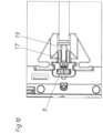
- Fig.7 shows a section through the drive device 1 in the area of the synchronization rod 5.
- the base part 18 rests on the support part 27.
- the synchronization element 6a is rotatably mounted in the pivot bearing part 26 and meshes with the transmission element 8a.
- a depth adjustment wheel 28 is shown.
- Fig.8 shows the synchronization rod 5 with the end region E before insertion into the receiving region 17 of the synchronization element 6a.
- the pull-out guides 22 mounted on the furniture body side walls and thus also the drawer side walls are also 6 mm further apart, which in turn is compensated for by a wider drawer floor.
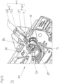
- Fig. 11 to 13 Details of the ejection device 3a are also visible.
- the locking lever 29 is essential in the area of the ejection device 3a. and the locking pin 13 arranged thereon, which engages in the heart-shaped guide track 14 formed in the housing 7 or is guided in it. Together, these components form the locking device 12 for the lockable ejection device 3a or 3b.
- the ejection element which is designed as a slide that is movably mounted in the housing. This slide is acted upon by an ejection spring.
- components are provided to enable coupling of this movement of the ejection slide with the driver 24 (catch fork and coupling element). According to Fig.
- the locking pin 13 is in the only partially visible locking recess 15.
- This locking recess 15 is also formed by the extension 30.
- This extension 30 is part of the transmission element 8a.
- This transmission element 8a is mounted on the housing 7 so that it can rotate about a preferably vertical axis of rotation.
- the rack-shaped area 10, which meshes with the gear 9 of the synchronization element 6a, is also formed on this transmission element 8a.
- the ejection device 3a is in the locking position VS due to the position of the locking pin 13.
- the drive device 1 is in the inactive synchronization mode S 0 due to the synchronization rod 5 not yet being inserted.
- the drive device 1 is located according to Fig. 12 in the active synchronization mode S 1 , since the synchronization rod 5 is inserted into the receiving area 17 via the attachment part 19.
- the ejection device 3a is, however, still in the locking position VS.
Landscapes
- Engineering & Computer Science (AREA)
- Mechanical Engineering (AREA)
- Drawers Of Furniture (AREA)
Description
- Die Erfindung betrifft eine Antriebsvorrichtung für ein bewegbares Möbelteil gemäß dem Oberbegriff des Anspruchs 1. Zudem betrifft die Erfindung ein Möbel mit einem Möbelkorpus und einem am Möbelkorpus bewegbar gelagerten Möbelteil und einer solchen Antriebsvorrichtung.
- Generell sind im Möbelbereich bereits zahlreiche Anwendungen bekannt, bei denen eine Synchronisierung meist aus dem Grund erfolgt, das bewegbare Möbelteil gleichmäßig zu bewegen und keine Schiefstellung zuzulassen. Beispiele für gattungsfremde Synchronisierungen bei Möbelklappen gehen aus der
WO 2011/047396A1 und derWO 2013/040611 A1 hervor. Demnach werden Stellvorrichtungen von Klappenbeschlägen über Synchronisierungsvorrichtungen synchronisiert. Dabei wird über die Synchronisationsstange jede Bewegung der Stellvorrichtungen immer auf die andere Stellvorrichtung übertragen. Es erfolgt beim Synchronisieren keine Relativbewegung zwischen den Synchronisationsstangen und den Stellantrieben. In der zweitgenannten Schrift ist zwar auch von einer sogenannten Touch-Latch-Vorrichtung zum Ausstoßen bewegbarer Möbelteile die Rede, jedoch wird über die in dieser Schrift gezeigte Synchronisationsstange immer die Bewegung der gesamten Stellvorrichtungen synchronisiert und nicht diese Touch-Latch-Vorrichtungen direkt synchronisiert. Vielmehr ist jede Synchronisationsstange ortsfest mit einem entsprechenden Arm jeder Stellvorrichtung verbunden. Es erfolgt keine Relativbewegung zwischen der Synchronisationsstange und diesem Arm der jeweiligen Stellvorrichtung. Weiters sind Synchronisierungsvorrichtungen auch bei gattungsfremden Seitenstabilisierungen bekannt. Hierzu kann auf dieEP 2 515 710 B1 verwiesen werden. Diese Seitenstabilisierungen dienen dazu, dass die Bewegungen der Ladenschienen an sich synchronisiert werden. Es findet sich in dieser gattungsfremden Schrift keine irgendwie geartete Ausstoßvorrichtung. Eine ähnliche Vorrichtung zur Seitenstabilisierung geht aus derWO 2012/159136 A1 hervor. Hierin geht es vor allem darum, dass zwischen Teilwellen einer Synchonisationsstange eine Überlastsicherungsvorrichtung angeordnet ist. - Demgegenüber zeigt die
EP 2 429 339 B1 einen gattungsbildenden Stand der Technik. Bei dieser Anordnung zum Verriegeln und Ausstoßen eines bewegbaren Möbelteils wird die Synchronisierung dadurch erreicht, dass am Ende einer Synchronisationsstange ein zahnradförmiges Drehelement angeordnet ist, das mit einer an der Ausstoßvorrichtung angebrachten Zahnstange kämmt. Nachteilig hierbei ist, dass beim Anbringen der Synchronisationsstange das Drehelement kompliziert in eine Haltebuchse eingefädelt werden muss. Hierbei kann es zu Zahnfehlern zwischen den Zähnen des Drehelementes und der Zahnstange kommen, wodurch die gesamte Synchronisationsstange schon ungewünscht schräg eingebaut werden könnte. Zudem muss die Zahnstange recht aufwändig mit einem Federelement ausgebildet sein, um ein Anpassen der Synchronisationsstangenlänge an unterschiedliche Abstände zwischen den beidseitigen Ausstoßvorrichtungen zu ermöglichen. Diese aufwändige Teleskopierbarkeit der Zahnstange ist notwendig, um überhaupt das Einsetzen und anschließende Halten der Synchronisationsstange an den beiden Ausstoßvorrichtungen zu erlauben. - Ein anderer gattungsbildender Stand der Technik geht aus der nicht vorveröffentlichten, österreichischen Patentanmeldung mit der Anmeldenummer
A 785/2013 AT 514 865 A1 - Die Aufgabe der vorliegenden Erfindung besteht daher darin, eine gegenüber dem Stand der Technik verbesserte Antriebsvorrichtung zu schaffen. Insbesondere soll die Synchronisierung möglichst einfach und unkompliziert erfolgen können.
- Dies wird durch eine Antriebsvorrichtung mit den Merkmalen von Anspruch 1 erreicht. Demnach ist vorgesehen, dass in einem aktiven Synchronisierungsmodus beim Synchronisieren eine Bewegungsweitergabe von der ersten Ausstoßvorrichtung über das erste Synchronisierungselement, die Synchronisierungsstange und das zweite Synchronisierungselement auf die zweite Ausstoßvorrichtung erfolgt und in einem inaktiven Synchronisierungsmodus die Synchronisierungsstange entfernt ist und die Synchronisierungselemente jeweils in Kontakt mit einer der Ausstoßvorrichtungen verbleiben. Mit anderen Worten werden somit die Synchronisierungselemente nicht mehr mitsamt der Synchronisierungsstange eingebaut und auch wieder entfernt, sondern die Synchronisierungselemente bleiben der jeweiligen Ausstoßvorrichtung zugeordnet. Somit bleibt jedes Synchronisierungselement immer in passendem ständigen Kontakt mit der Ausstoßvorrichtung, wodurch es zu keinem ungewünschten schrägen Zusammenbauen, beispielsweise mit einem Zahnfehler, kommen kann. Wiederum anders ausgedrückt machen die Synchronisierungselemente auch in einem inaktiven Synchronisierungsmodus immer die Bewegungen der Ausstoßvorrichtung zum Teil mit. Aufgrund der fehlenden Synchronisierungsstange erfolgt aber keine Weiterleitung dieser Bewegung zwischen den beiden Synchronisierungselementen.
- Bei der Relativbewegung zwischen den Synchronisierungselementen und, vorzugsweise allen Komponenten, der Ausstoßvorrichtung kann eine Bewegungsumwandlung einer Drehbewegung in eine translatorische Bewegung stattfinden. Bevorzugt ist vorgesehen, dass die Bewegungsumwandlung von einer Drehbewegung um eine erste Drehachse in eine Drehbewegung um eine anders ausgerichtete Drehachse erfolgt (Bevorzugt stehen diese Drehachsen rechtwinkelig zueinander).
- Erfindungsgemäß ist es vorgesehen, dass die Ausstoßvorrichtungen jeweils ein Gehäuse und ein am Gehäuse bewegbar, vorzugsweise drehbar, gelagertes Übertragungselement aufweisen, wobei die Synchronisierungselemente jeweils mit einem der Übertragungselemente bewegungsgekoppelt sind. Prinzipiell kann hierbei die Bewegungskoppelung beispielsweise über Reibräder erfolgen. Bevorzugt wird die Bewegungskoppelung allerdings über einen Formschluss erreicht. Demnach ist bevorzugt vorgesehen, dass jedes Synchronisierungselement ein Zahnrad und jedes Übertragungselement einen zahnstangenförmigen Bereich aufweist, wobei die Zahnräder jeweils mit einem der zahnstangenförmigen Bereiche kämmen. Es soll nicht ausgeschlossen sein, dass die Synchronisierungselemente zahnstangenförmig, und gegebenenfalls translatorisch bewegbar, ausgebildet sind, während die Übertragungselemente als Zahnräder ausgebildet sind.
- Im Allgemeinen kann die Ausstoßvorrichtung beliebig ausgebildet sein, solange ein aktives Ausstoßen des bewegbaren Möbelteils aus einer Schließstellung in Öffnungsrichtung möglich ist. Erfindungsgemäß ist es vorgesehen, dass jede Ausstoßvorrichtung ein kraftbeaufschlagtes Ausstoßelement zum Ausstoßen des bewegbaren Möbelteils aus einer Schließstellung in eine Offenstellung und eine Verriegelungsvorrichtung zum Verriegeln des Ausstoßelements in einer Verriegelungsstellung aufweist, wobei durch Überdrücken des bewegbaren Möbelteils in eine hinter der Schließstellung liegende Überdrückstellung die Verriegelungsvorrichtung entriegelbar ist. Besonders bevorzugt ist dabei vorgesehen, dass die Verriegelungsvorrichtung einen Verriegelungszapfen und eine im Gehäuse ausgebildete, vorzugsweise herzkurvenförmige, Kulissenbahn aufweist. Weiters kann vorgesehen sein, dass jedes Übertragungselement jeweils einen Teil der Kulissenbahn, vorzugsweise eine Rastmulde der herzkurvenförmigen Kulissenbahn, mitbildet. Somit wird durch die Synchronisierungsvorrichtung nur ein kleiner Teil der Bewegung der Ausstoßvorrichtung synchronisiert, nämlich der Teil, in welchem sich das Übertragungselement aufgrund der Auslösebewegung kurz nach dem Überdrücken bewegt.
- Erfindungsgemäß ist es vorgesehen, dass von der Synchronisierungsvorrichtung nur ein erster Abschnitt einer Öffnungsbewegung des bewegbaren Möbelteils, der unmittelbar auf die Überdrückstellung folgt, synchronisierbar ist. Inhaltlich kann hierzu auf die nicht vorveröffentlichte, österreichische Patentanmeldung
A 785/2013 - Um ein problemloses Halten der Synchronisationselemente an den Ausstoßvorrichtungen zu ermöglichen, ist bevorzugt vorgesehen, dass jedes Synchronisierungselement jeweils über ein Lagerelement am Gehäuse der Ausstoßvorrichtung, vorzugsweise drehbar und vorzugsweise axial feststehend, gelagert ist. Durch die drehbare Lagerung und durch das axiale Feststehen kann das Synchronisierungselement jede Bewegung des Übertragungselementes mitmachen, ohne dass eine Fehlstellung zwischen diesen Teilen auftreten kann.
- Für die gute Bewegungsübertragung im aktiven Synchronisierungsmodus ist bevorzugt vorgesehen, dass die Synchronisierungsstange an beiden Endbereichen einen nicht-kreisförmigen Querschnitt aufweist und jedes Synchronisierungselement einen der Außenkontur der Endbereiche der Synchronisierungsstange zumindest abschnittsweise angepassten Aufnahmebereich aufweist. Mit diesem nicht-kreisförmigen Querschnitt wird ein Formschluss zwischen den beteiligten Komponenten erreicht. Dieser nichtkreisförmige Querschnitt kann beispielsweise dreieckig sein. Es ist auch möglich, dass dieser Endbereich im Großteil kreisförmig ausgebildet ist und nur einen abgeflachten Abschnitt aufweist. Besonders bevorzugt ist dieser nichtkreisförmige Querschnitt allerdings quadratisch ausgebildet. Dies hat den Vorteil einer einfachen Herstellung. Darüber hinaus ist ein Verwinden der gesamten Synchronisationsstange um 90° praktisch unmöglich. Bisher war durch ein geringes Verwinden bereits ein Zahnfehler möglich. Da zudem das Zahnrad bzw. das Synchronisationselement an der Ausstoßvorrichtung vormontiert ist, sind solche Fehler nun ausgeschlossen.
- In Betriebszustand ist das Synchronisationselement unlösbar mit der Ausstoßvorrichtung verbunden. Nur die Synchronisationsstange ist zerstörungsfrei lösbar am Synchronisierungselement eingesetzt bzw. mit dieser verbunden.
- Prinzipiell kann die Synchronisierungsstange einstückig ausgebildet sein und eben die entsprechenden Endbereiche aufweisen. Zum Beispiel kann die Synchronisierungsstange als ein durchgehender Vierkant ausgebildet sein. Bevorzugt ist allerdings vorgesehen, dass die Synchronisierungsstange ein rundes stangenförmiges, vorzugsweise über die gesamte Länge als Hohlprofil mit gleichem Innendurchmesser ausgebildetes, Basisteil und zwei an den Enden des Basisteils befestigbare, die Endbereiche bildende Ansteckteile aufweist.
- Ein besonderer Vorteil gegenüber bisherigen Ausführungen der Synchronisierungsstange besteht darin, dass die Synchronisierungsstange längenunveränderlich ausgebildet ist. Das heißt, die Synchronisierungsstange muss nicht in sich teleskopierbar ausgebildet sein. Vielmehr wird dadurch, dass der Aufnahmebereich der Synchronisierungselemente länglich ausgebildet ist, eine gewisse Abstandstoleranz erreicht. Zudem wird über diese Synchronisierungsstange nur eine Momentübertragung durchgeführt.
- Schutz wird auch begehrt für ein Möbel mit einem Möbelkorpus, einem am Möbelkorpus, vorzugsweise über eine Auszugsführung, bewegbar gelagerten Möbelteil und einer erfindungsgemäßen Antriebsvorrichtung. Die Antriebsvorrichtung kann dabei am Möbelkorpus angeordnet bzw. über eine Korpusschiene befestigt sein. Bevorzugt ist die Antriebsvorrichtung dem bewegbaren Möbelteil zugeordnet, besonders bevorzugt an der Unterseite des bewegbaren Möbelteils montiert.
- Weitere Einzelheiten und Vorteile der vorliegenden Erfindung werden anhand der Figurenbeschreibung unter Bezugnahme auf die in den Zeichnungen dargestellten Ausführungsbeispiele im Folgenden näher erläutert. Darin zeigen:
- Fig. 1
- eine perspektivische Ansicht des Möbels,
- Fig. 2
- eine Ansicht des bewegbaren Möbelteils von unten im aktiven Synchronisierungsmodus,
- Fig. 3
- eine Ansicht des bewegbaren Möbelteils von unten im inaktiven Synchronisierungsmodus,
- Fig. 4 und 5
- Details von
Fig. 2 , - Fig. 6
- ein Detail von
Fig. 3 , - Fig. 7
- einen teilweisen Schnitt durch den Bereich der Synchronisierungsstange und eines Synchronisierungselements,
- Fig. 8
- die Synchronisierungsstange vor dem Einsetzen in ein Lagerelement,
- Fig. 9 und 10
- eine Draufsicht auf den Lagerbereich der Synchronisierungsstange mit unterschiedlich tief in das Lagerelement hineinragenden Endbereichen,
- Fig. 11 bis 13
- Details der Ausstoßvorrichtung bei unterschiedlichen Stellungen der Synchronisierungsvorrichtung.
- In
Fig. 1 ist ein Möbel 20 mit einem Möbelkorpus 21 und zwei darin bewegbar gelagerten bewegbaren Möbelteilen 2 dargestellt. Diese beiden bewegbaren Möbelteile 2 sind als Schubladen ausgebildet, wobei sich die obere Schublade in einer Offenstellung OS und die untere Schublade in einer Schließstellung SS befindet. - Wie in
Fig. 2 erkennbar, ist ein solches bewegbares Möbelteil 2 über eine Ausziehführung 22 mit dem hier nicht dargestellten Möbelkorpus 21 verbunden. An der Unterseite des bewegbaren Möbelteils 2, im Speziellen am Schubladenboden, sind auf beiden Seiten jeweils Ausstoßvorrichtungen 3a und 3b angeordnet. Diese Ausstoßvorrichtungen 3a und 3b sind jeweils zumindest abschnittsweise mit Mitnehmern 24 gekoppelt. Diese Mitnehmer 24 sind wiederum über Halteplatten 23 an den Ausziehführungen 22, im Speziellen an deren Korpusschienen 25, befestigt. Beim Ausstoßen stößt sich somit das bewegbare Möbelteil 2 über die beiden Ausstoßvorrichtungen 3a und 3b an den korpusfesten Mitnehmern 24 ab und bewegt das bewegbare Möbelteil in Öffnungsrichtung. Um vor allem bei breiten Schubladen (ab ca. 60 cm) ein Schrägstellen der Schublade beim Ausstoßen zu verhindern, ist eine Synchronisierungsvorrichtung 4 vorgesehen. Diese Synchronisierungsvorrichtung 4 bildet mit den beiden verriegelbaren Ausstoßvorrichtungen 3a und 3b zusammen die Antriebsvorrichtung 1. In diesem Fall befindet sich die Antriebsvorrichtung 1 in einem aktiven Synchronisierungsmodus S1. - Demgegenüber befindet sich die Antriebsvorrichtung 1 in
Fig. 3 in einem inaktiven Synchronisierungsmodus S0, in dem die Synchronisierungsstange 5 der Synchronisierungsvorrichtung 4 entfernt ist. Die beiden Synchronisierungselemente 6a und 6b bleiben aber auch in diesem inaktiven Synchronisierungsmodus S0 jeweils in direktem Kontakt mit einer der Ausstoßvorrichtungen 3a und 3b bzw. im Speziellen mit den Übertragungselementen 8a und 8b. Somit sind die Synchronisierungselemente 6a und 6b - im Gegensatz zum gattungsbildenden Stand der Technik - immer den Ausstoßvorrichtungen 3a und 3b zugeordnet und werden nicht mit dem Entfernen der Synchronisierungsstange 5 ebenfalls entfernt. Die Synchronisierungselemente 6a und 6b sind somit an den Ausstoßvorrichtungen 3a und 3b vormontiert und mit diesen in Betriebszustand unlösbar verbunden. -
Fig. 4 zeigt nochmals im Detail vor allem die Korpusschiene 25 und den daran über die Halteplatte 23 befestigten Mitnehmer 24. Im Bereich der Ausziehführung 22 kann auch eine Einziehvorrichtung zum, vorzugsweise gedämpften, Einziehen des bewegbaren Möbelteils 2 aus einer Offenstellung OS in die Schließstellung SS vorgesehen sein. Die Ausstoßvorrichtung 3a weist als separate bzw. eigenständige Baueinheit ein Gehäuse 7 auf, an dem auch das Lagerelement 16 für die Synchronisierungsvorrichtung 4 angeordnet ist. Dieses Lagerelement 16 kann einstückig mit dem Gehäuse 7 ausgebildet sein. - Wie in
Fig. 5 aber erkennbar, ist das Lagerelement 16 separat vom Gehäuse 7 ausgebildet. Bevorzugt weist das Lagerelement 16 selbst zwei Bauteile, nämlich das Drehlagerteil 26 und das Auflageteil 27 auf. Am Drehlagerteil 26 ist das Synchronisierungselement 6a drehbar und axial feststehend gelagert bzw. gehalten, während am Auflageteil 27 vor allem die Synchronisierungsstange 5 aufliegt und geführt ist. In dieserFig. 5 ist auch ersichtlich, dass das Synchronisierungselement 6a einerseits das Zahnrad 9 und andererseits den Aufnahmebereich 17 aufweist. Das Synchronisierungselement 6a ist bevorzugt separat von allen Komponenten (Stellelementen) der Ausstoßvorrichtung 3a ausgebildet. Bevorzugt ist dieses Synchronisierungselement 6a einstückig ausgebildet. Demgegenüber ist die Synchronisierungsstange 5 bevorzugt zweistückig bzw. dreistückig und weist an beiden Endbereichen E ein Ansteckteil 19 auf, das in das Basisteil 18 einsteckbar ist. Gemeinsam bilden die Synchronisierungsstange 5 sowie die beiden Synchronisierungselemente 6a und 6b die Synchronisierungsvorrichtung 4. Wie bereits in dieserFig. 5 gut erkennbar ist, weist die Synchronisierungsstange 5 an beiden Endbereichen E einen nicht-kreisförmigen Querschnitt auf. Dazu passend weist jedes Synchronisierungselement 6a und 6b einen dieser Außenkontur der Endbereiche E der Synchronisierungsstange 5 zumindest abschnittsweise angepassten Aufnahmebereich 17 auf. - In
Fig. 6 ist die Synchronisierungsstange 5 entfernt, womit sich die Antriebsvorrichtung 1 in einem inaktiven Synchronisierungsmodus S0 befindet. Wie inFig. 6 gut erkennbar, verbleibt das Synchronisierungselement 6a auch im inaktiven Synchronisierungsmodus S0 an der Ausstoßvorrichtung 3a. -
Fig. 7 zeigt einen Schnitt durch die Antriebsvorrichtung 1 im Bereich der Synchronisationsstange 5. Wie in dieserFig. 7 gut ersichtlich ist, liegt das Basisteil 18 am Auflageteil 27 auf. Das Synchronisierungselement 6a ist im Drehlagerteil 26 drehbar gelagert und kämmt mit dem Übertragungselement 8a. Weiters ist in dieserFig. 7 ein Tiefenverstellrad 28 dargestellt. -
Fig. 8 zeigt die Synchronisierungsstange 5 mit dem Endbereich E vor dem Einsetzen in den Aufnahmebereich 17 des Synchronisierungselements 6a. - Im Vergleich zwischen den
Fig. 9 und10 ist erkennbar, dass aufgrund der Länge des Aufnahmebereichs 17 die Synchronisierungsstange 5 und dessen Ansteckteil 19 unterschiedlich tief in den Aufnahmebereich 17 hineinragen. Dies ermöglicht ein unkompliziertes Synchronisieren bzw. Bringen der Antriebsvorrichtung 1 in den aktiven Synchronisierungsmodus S1, auch wenn die Ausstoßvorrichtungen 3a und 3b unterschiedlich weit voneinander entfernt sein sollten. Dies ist vor allem dann der Fall, wenn unterschiedlich breite Schubladenseitenböden bzw. Fachböden verwendet werden. Diese Breite des Bodens ist wiederum abhängig von der Dicke der Möbelkorpusseitenwand. Wenn nämlich bei gleichbleibendem Möbelkorpusaußenmaß dünnere Möbelkorpusseitenwände (16 statt 19 mm) verwendet werden, so sind auch die an den Möbelkorpusseitenwänden montierten Ausziehführungen 22 und damit auch die Schubladenseitenwände um 6 mm weiter voneinander entfernt, was wiederum durch einen breiteren Schubladenboden ausgeglichen wird. - In den
Fig. 11 bis 13 sind auch Details der Ausstoßvorrichtung 3a ersichtlich. Wesentlich im Bereich der Ausstoßvorrichtung 3a ist der Verriegelungshebel 29 und der daran angeordnete Verriegelungszapfen 13, der in die im Gehäuse 7 ausgebildete herzkurvenförmige Kulissenbahn 14 eingreift bzw. in dieser geführt ist. Zusammen bilden diese Komponenten die Verriegelungsvorrichtung 12 für die verriegelbare Ausstoßvorrichtung 3a bzw. 3b. Nicht dargestellt in diesenFig. 11 bis 13 ist das Ausstoßelement, welches als ein im Gehäuse verfahrbar gelagerter Schlitten ausgebildet ist. Dieser Schlitten ist von einer Ausstoßfeder kraftbeaufschlagt. Zudem sind Komponenten vorgesehen, um eine Koppelung dieser Bewegung des Ausstoßschlittens mit den Mitnehmer 24 zu ermöglichen (Fanggabel und Koppelelement). GemäßFig. 11 befindet sich der Verriegelungszapfen 13 in der nur ansatzweise erkennbaren Rastmulde 15. Dieser Rastmulde 15 wird auch vom Fortsatz 30 mitgebildet. Dieser Fortsatz 30 ist Teil des Übertragungselements 8a. Dieses Übertragungselement 8a ist um eine, vorzugsweise vertikale, Drehachse am Gehäuse 7 drehbar gelagert. An diesem Übertragungselement 8a ist auch der zahnstangenförmige Bereich 10 ausgebildet, der mit dem Zahnrad 9 des Synchronisierungselements 6a kämmt. Die Ausstoßvorrichtung 3a befindet sich aufgrund der Stellung des Verriegelungszapfens 13 in der Verriegelungsstellung VS. Die Antriebsvorrichtung 1 befindet sich aufgrund der noch nicht eingesetzten Synchronisierungsstange 5 im inaktiven Synchronisierungsmodus S0. - Dagegen befindet sich die Antriebsvorrichtung 1 gemäß
Fig. 12 im aktiven Synchronisierungsmodus S1, da die Synchronisierungsstange 5 über das Ansteckteil 19 in den Aufnahmebereich 17 eingesetzt ist. Die Ausstoßvorrichtung 3a befindet sich aber noch in Verriegelungsstellung VS. - Demgegenüber wurde gemäß
Fig. 13 bereits eine Überdrückbewegung durchgeführt. Dadurch gelangt das bewegbare Möbelteil 2 und der Verriegelungszapfen 13 aus der Rastmulde 15 in eine (nicht dargestellte) Überdrückstellung. Beim anschließenden Bewegen in Ausstoßrichtung wird von diesem Verriegelungszapfen 13 auch der Fortsatz 30 mitgenommen, wodurch sich das Übertragungselement 8a im Uhrzeigersinn dreht. Mit dieser Drehung des Übertragungselements 8a wird über den zahnstangenförmigen Bereich 10 auch eine Bewegung des Zahnrades 9 und mithin der Synchronisierungsstange 5 gegen den Uhrzeigersinn ausgelöst. Im Vergleich zuFig. 12 hat sich die Synchronisationsstange 5 fast um 270° gedreht. Bei dieser Drehung bleibt der Formschluss zwischen dem Aufnahmebereich 17 und dem Ansteckteil 19 vor allem dadurch erhalten, dass die Synchronisierungsstange 5 im Lagerelement 16 axial und radial feststehend gehalten ist. Beim weiteren Ausstoßvorgang erfolgt keine Synchronisierung mehr. Vielmehr wird bei dieser Synchronisierungsvorrichtung 4 nur die Entriegelungsbewegung des Verriegelungszapfens 13 aus der Rastmulde 15 synchronisiert. Natürlich wird beim Einschieben des Verriegelungszapfens 13 in die Verriegelungsstellung VS das Übertragungselement 8 über den Hebel 31 wieder in die Position gemäßFig. 12 zurückbewegt. - Je nachdem auf welcher Seite bei einem ungleichmäßigen Auslösen zuerst die Entriegelung erfolgt, wird dann diese Bewegung entsprechend auf die andere Seite weitergeleitet, sodass dort der Fortsatz 30 aufgrund der Synchronisierung ebenfalls wegbewegt wird, wodurch sich der Verriegelungszapfen 13 nicht mehr in der Rastmulde 15 halten kann und somit auf beiden Seiten gleichzeitig der Ausstoßvorgang mit sich gleichzeitig bzw. synchron entspannenden Ausstoßkraftspeichern (nicht dargestellt) erfolgt.
- Generell sei noch darauf hingewiesen, dass natürlich die entsprechenden Komponenten auf der jeweils anderen Seite spiegelsymmetrisch ausgebildet sind. Wenn also in der Beschreibung von nur auf ein Teil einer Seite Bezug genommen wird, so gilt dies sinngemäß auch für die andere Seite.
-
- 1
- Antriebsvorrichtung
- 2
- bewegbares Möbelteil
- 3a
- erste verriegelbare Ausstoßvorrichtung
- 3b
- zweite verriegelbare Ausstoßvorrichtung
- 4
- Synchronisierungsvorrichtung
- 5
- Synchronisierungsstange
- 6a, b
- Synchronisierungselemente
- 7
- Gehäuse
- 8a, b
- Übertragungselemente
- 9
- Zahnrad
- 10
- zahnstangenförmiger Bereich
- 12
- Verriegelungsvorrichtung
- 13
- Verriegelungszapfen
- 14
- Kulissenbahn
- 15
- Rastmulde
- 16
- Lagerelement
- 17
- Aufnahmebereich
- 18
- Basisteil
- 19a, b
- Ansteckteile
- 20
- Möbel
- 21
- Möbelkorpus
- 22
- Ausziehführung
- 23
- Halteplatte
- 24
- Mitnehmer
- 25
- Korpusschiene
- 26
- Drehlagerteil
- 27
- Auflageteil
- 28
- Tiefenverstellrad
- 29
- Verriegelungshebel
- 30
- Fortsatz
- 31
- Hebel
- S1
- aktiver Synchronisierungsmodus
- S0
- inaktiver Synchronisierungsmodus
- SS
- Schließstellung
- OS
- Offenstellung
- VS
- Verriegelungsstellung
- E
- Endbereiche
Claims (7)
- Antriebsvorrichtung (1) für ein bewegbares Möbelteil (2), insbesondere eine Schublade, mit einer ersten und einer zweiten verriegelbaren Ausstoßvorrichtung (3a, 3b) und einer Synchronisierungsvorrichtung (4) zum Synchronisieren der beiden Ausstoßvorrichtungen (3a, 3b), wobei die Synchronisierungsvorrichtung (4) eine Synchronisierungsstange (5) und ein erstes und ein zweites mit der Synchronisierungsstange (5) verbindbares Synchronisierungselement (6a, 6b) aufweist und wobei zwischen den Synchronisierungselementen (6a, 6b) und den Ausstoßvorrichtungen (3a, 3b) beim Synchronisieren eine Relativbewegung stattfindet, wobei- in einem aktiven Synchronisierungsmodus (S1) beim Synchronisieren eine Bewegungsweitergabe von der ersten Ausstoßvorrichtung (3a) über das erste Synchronisierungselement (6a), die Synchronisierungsstange (5) und das zweite Synchronisierungselement (6b) auf die zweite Ausstoßvorrichtung (3b) erfolgt und- in einem inaktiven Synchronisierungsmodus (S0) die Synchronisierungsstange (5) entfernt ist und die Synchronisierungselemente (6a, 6b) jeweils in Kontakt mit einer der Ausstoßvorrichtungen (3a, 3b) verbleiben, und wobeidie Ausstoßvorrichtungen (3a, 3b) jeweils ein Gehäuse (7) und ein am Gehäuse (7) bewegbar, vorzugsweise drehbar, gelagertes Übertragungselement (8a, 8b) aufweisen, wobei die Synchronisierungselemente (6a, 6b) jeweils mit einem der Übertragungselemente (8a, 8b) bewegungsgekoppelt sind, jede Ausstoßvorrichtung (3a, 3b) ein kraftbeaufschlagtes Ausstoßelement zum Ausstoßen des bewegbaren Möbelteils (2) aus einer Schließstellung (SS) in eine Offenstellung (OS) und eine Verriegelungsvorrichtung (12) zum Verriegeln des Ausstoßelements in einer Verriegelungsstellung (VS) aufweist, wobei die Verriegelungsvorrichtung (12) einen Verriegelungszapfen (13) und eine im Gehäuse (7) ausgebildete, vorzugsweise herzkurvenförmige, Kulissenbahn (14) aufweist, wobei jedes Übertragungselement (8a, 8b) jeweils einen Teil der Kulissenbahn (14), vorzugsweise eine Rastmulde (15) der herzkurvenförmigen Kulissenbahn (14), mitbildet, wobei durch Überdrücken des bewegbaren Möbelteils (2) in eine hinter der Schließstellung (SS) liegende Überdrückstellung die Verriegelungsvorrichtung (12) entriegelbar ist, wobei von der Synchronisierungsvorrichtung (4) nur ein erster Abschnitt einer Öffnungsbewegung des bewegbaren Möbelteils (2), der unmittelbar auf die Überdrückstellung folgt, synchronisierbar ist.
- Antriebsvorrichtung nach Anspruch 1, dadurch gekennzeichnet, dass jedes Synchronisierungselement (6a, 6b) ein Zahnrad (9) und jedes Übertragungselement (8a, 8b) einen zahnstangenförmigen Bereich (10) aufweist, wobei die Zahnräder (9) jeweils mit einem der zahnstangenförmigen Bereiche (10) kämmen.
- Antriebsvorrichtung nach einem der Ansprüche 1 bis 2, dadurch gekennzeichnet, dass jedes Synchronisierungselement (6a, 6b) jeweils über ein Lagerelement (16) am Gehäuse (7) der Ausstoßvorrichtung (3a, 3b), vorzugsweise drehbar und vorzugsweise axial feststehend, gelagert ist.
- Antriebsvorrichtung nach einem der Ansprüche 1 bis 3, dadurch gekennzeichnet, dass die Synchronisierungsstange (5) an beiden Endbereichen (E) einen nicht-kreisförmigen Querschnitt aufweist und jedes Synchronisierungselement (6a, 6b) einen der Außenkontur der Endbereiche (E) der Synchronisierungsstange (5) zumindest abschnittsweise angepassten Aufnahmebereich (17) aufweist.
- Antriebsvorrichtung nach Anspruch 4, dadurch gekennzeichnet, dass die Synchronisierungsstange (5) ein stangenförmiges, vorzugsweise über die gesamte Länge als Hohlprofil mit gleichem Innendurchmesser ausgebildetes, Basisteil (18) und zwei an den Enden des Basisteils (18) befestigbare, die Endbereiche (E) bildende Ansteckteile (19a, 19b) aufweist.
- Antriebsvorrichtung nach einem der Ansprüche 1 bis 5, dadurch gekennzeichnet, dass die Synchronisierungsstange (5) längenunveränderlich ausgebildet ist.
- Möbel (20) mit einem Möbelkorpus (21), einem am Möbelkorpus (21), vorzugsweise über eine Ausziehführung (22), bewegbar gelagerten Möbelteil (2) und einer Antriebsvorrichtung (1) nach einem der Ansprüche 1 bis 6.
Applications Claiming Priority (3)
| Application Number | Priority Date | Filing Date | Title |
|---|---|---|---|
| AT4752014 | 2014-06-16 | ||
| PCT/AT2015/000062 WO2015192153A1 (de) | 2014-06-16 | 2015-05-04 | Antriebsvorrichtung für ein bewegbares möbelteil |
| EP15729065.1A EP3154398B1 (de) | 2014-06-16 | 2015-05-04 | Antriebsvorrichtung für ein bewegbares möbelteil |
Related Parent Applications (1)
| Application Number | Title | Priority Date | Filing Date |
|---|---|---|---|
| EP15729065.1A Division EP3154398B1 (de) | 2014-06-16 | 2015-05-04 | Antriebsvorrichtung für ein bewegbares möbelteil |
Publications (2)
| Publication Number | Publication Date |
|---|---|
| EP3957209A1 EP3957209A1 (de) | 2022-02-23 |
| EP3957209B1 true EP3957209B1 (de) | 2024-08-21 |
Family
ID=53397737
Family Applications (2)
| Application Number | Title | Priority Date | Filing Date |
|---|---|---|---|
| EP15729065.1A Active EP3154398B1 (de) | 2014-06-16 | 2015-05-04 | Antriebsvorrichtung für ein bewegbares möbelteil |
| EP21200163.0A Active EP3957209B1 (de) | 2014-06-16 | 2015-05-04 | Antriebsvorrichtung für ein bewegbares möbelteil |
Family Applications Before (1)
| Application Number | Title | Priority Date | Filing Date |
|---|---|---|---|
| EP15729065.1A Active EP3154398B1 (de) | 2014-06-16 | 2015-05-04 | Antriebsvorrichtung für ein bewegbares möbelteil |
Country Status (9)
| Country | Link |
|---|---|
| US (1) | US10143303B2 (de) |
| EP (2) | EP3154398B1 (de) |
| JP (1) | JP6412594B2 (de) |
| CN (1) | CN106455812B (de) |
| AT (1) | AT14687U1 (de) |
| ES (2) | ES3001125T3 (de) |
| MY (1) | MY178802A (de) |
| TW (1) | TWI595849B (de) |
| WO (1) | WO2015192153A1 (de) |
Families Citing this family (19)
| Publication number | Priority date | Publication date | Assignee | Title |
|---|---|---|---|---|
| AT516733B1 (de) * | 2015-04-14 | 2016-08-15 | Blum Gmbh Julius | Antriebsvorrichtungen samt Synchronisierungsvorrichtung für ein bewegbares Möbelteil |
| AT15246U1 (de) * | 2015-07-07 | 2017-04-15 | Blum Gmbh Julius | Antriebsvorrichtung für ein bewegbares Möbelteil |
| DE202015104439U1 (de) * | 2015-08-21 | 2016-11-22 | Grass Gmbh | Vorrichtung zum Bewegen eines bewegbaren Möbelteils und Möbel |
| DE202015106773U1 (de) * | 2015-12-14 | 2017-03-15 | Grass Gmbh | Auswerferanordnung für ein bewegbares Möbelteil |
| DE102016120584A1 (de) * | 2016-10-27 | 2018-05-03 | Paul Hettich Gmbh & Co. Kg | Möbel und Verfahren zum Öffnen eines Schubkastens und eines Innenschubkastens |
| DE102016120585A1 (de) * | 2016-10-27 | 2018-05-03 | Paul Hettich Gmbh & Co. Kg | Möbel |
| DE102016120588A1 (de) * | 2016-10-27 | 2018-05-03 | Paul Hettich Gmbh & Co. Kg | Möbel und Verfahren zum Öffnen eines Schubkastens und eines Innenschubkastens |
| TWI629027B (zh) * | 2017-03-20 | 2018-07-11 | 川湖科技股份有限公司 | 用於滑軌總成的同步系統 |
| DE102017108453A1 (de) * | 2017-04-20 | 2018-10-25 | Paul Hettich Gmbh & Co. Kg | Möbel |
| AT520767B1 (de) * | 2018-01-02 | 2023-05-15 | Blum Gmbh Julius | Anordnung aus einem Auflagesteg für einen Schubladenboden und einer Haltevorrichtung |
| AT520789B1 (de) * | 2018-01-12 | 2020-07-15 | Blum Gmbh Julius | Anordnung aus Ausziehführung und Mitnehmer |
| AT520817B1 (de) * | 2018-02-01 | 2019-08-15 | Blum Gmbh Julius | Anordnung aus Ausziehführung, Schienen-Synchronisierungsvorrichtung und Mitnehmer |
| AT522397B1 (de) * | 2019-03-20 | 2021-08-15 | Blum Gmbh Julius | Antriebsvorrichtung für ein bewegbares Möbelteil |
| CN111821495B (zh) * | 2019-04-19 | 2021-07-23 | 宁波方太厨具有限公司 | 一种抽屉结构及消毒柜 |
| TWI699176B (zh) * | 2019-05-27 | 2020-07-21 | 川湖科技股份有限公司 | 用於滑軌總成的同步系統、同步裝置及方法 |
| CN113749436B (zh) * | 2020-06-01 | 2022-11-22 | 青岛海尔电冰箱有限公司 | 抽屉组件 |
| CN113470549B (zh) * | 2021-07-22 | 2022-10-21 | 深圳市宇祥兴光电有限公司 | 一种液晶显示屏 |
| DE102021120909A1 (de) * | 2021-08-11 | 2023-02-16 | Grass Gmbh | Vorrichtung und Möbel mit einem Möbelteil |
| CN119730753A (zh) * | 2022-08-15 | 2025-03-28 | 沙美卡尺和矿业灯具有限公司 | 具有用于弹出可移动家具零件的两个装置的设备 |
Family Cites Families (21)
| Publication number | Priority date | Publication date | Assignee | Title |
|---|---|---|---|---|
| AT502937B1 (de) * | 2005-04-28 | 2013-06-15 | Blum Gmbh Julius | Schrankförmiges möbel |
| DE202006012347U1 (de) * | 2006-08-10 | 2007-12-13 | Grass Gmbh | Vorrichtung zur Verriegelung eines Möbelteils und Möbel |
| AT506543B1 (de) * | 2008-03-19 | 2012-12-15 | Blum Gmbh Julius | Feststellvorrichtung zum arretieren eines in oder an einem möbel bewegbar gelagerten möbelteiles |
| MX2008005013A (es) * | 2008-04-17 | 2009-10-19 | Mabe Sa De Cv | Viga soporte para cajones en gabinetes. |
| GB2472959B (en) * | 2008-08-07 | 2013-04-10 | Accuride Int Inc | A synchronizing/stabilizing system and self moving mechanism for drawer applications |
| AT507656B1 (de) * | 2009-05-13 | 2010-07-15 | Blum Gmbh Julius | Anordnung zum verriegeln und ausstossen eines möbelteils |
| DE202009016105U1 (de) * | 2009-07-06 | 2010-12-02 | Paul Hettich Gmbh & Co. Kg | Synchronführung eine Schubelements und Möbel |
| US8632141B2 (en) * | 2009-08-12 | 2014-01-21 | Segos Co., Ltd. | Sliding apparatus with self-closing means |
| AT508959B1 (de) * | 2009-10-23 | 2012-06-15 | Blum Gmbh Julius | Synchronisationsvorrichtung zum synchronisieren zweier stellantriebe zum bewegen eines bewegbaren möbelteiles |
| AT509256B1 (de) * | 2009-12-23 | 2013-06-15 | Blum Gmbh Julius | Schienensystem für schubladen |
| AT509257B1 (de) | 2009-12-23 | 2013-09-15 | Blum Gmbh Julius | Schienensystem für schubladen |
| AT511045A1 (de) * | 2011-01-28 | 2012-08-15 | Blum Gmbh Julius | Möbelteil mit einer drehmomentübertragenden welle |
| TW201234995A (en) * | 2011-02-23 | 2012-09-01 | Chong-Yao Chen | Draw-pull synchronization device of side-sliding slide rail and slide rail unit thereof |
| AT511511B1 (de) * | 2011-05-20 | 2015-05-15 | Blum Gmbh Julius | Synchronisationsvorrichtung für ein bewegbar gelagertes möbelteil |
| AT511335B1 (de) | 2011-09-20 | 2012-11-15 | Blum Gmbh Julius | Synchronisationsvorrichtung zum bewegen von möbelteilen |
| TW201320927A (zh) * | 2011-11-21 | 2013-06-01 | 陳崇堯 | 抽拉同步裝置及其軸裝單元 |
| AT512165B1 (de) | 2011-12-27 | 2013-06-15 | Blum Gmbh Julius | Antriebsvorrichtung für ein bewegbares möbelteil |
| AT511964B1 (de) * | 2011-12-27 | 2013-04-15 | Blum Gmbh Julius | Antriebsvorrichtung für ein bewegbares möbelteil |
| DE202012002378U1 (de) * | 2012-03-08 | 2013-06-10 | Grass Gmbh | Führungseinrichtung zur Führung eines relativ zu einem Möbelkorpus bewegbaren Möbelteils |
| TWM454775U (zh) * | 2012-07-03 | 2013-06-11 | Nan Juen Int Co Ltd | 滑軌同步式連動裝置 |
| AT514865B1 (de) | 2013-10-11 | 2018-03-15 | Blum Gmbh Julius | Antriebsvorrichtung zum Bewegen eines bewegbaren Möbelteils |
-
2014
- 2014-06-16 AT ATGM8026/2015U patent/AT14687U1/de not_active IP Right Cessation
-
2015
- 2015-05-04 EP EP15729065.1A patent/EP3154398B1/de active Active
- 2015-05-04 ES ES21200163T patent/ES3001125T3/es active Active
- 2015-05-04 CN CN201580031999.9A patent/CN106455812B/zh active Active
- 2015-05-04 WO PCT/AT2015/000062 patent/WO2015192153A1/de not_active Ceased
- 2015-05-04 EP EP21200163.0A patent/EP3957209B1/de active Active
- 2015-05-04 MY MYPI2016002138A patent/MY178802A/en unknown
- 2015-05-04 JP JP2016572821A patent/JP6412594B2/ja active Active
- 2015-05-04 ES ES15729065T patent/ES2900833T3/es active Active
- 2015-05-27 TW TW104116921A patent/TWI595849B/zh active
-
2016
- 2016-12-15 US US15/380,368 patent/US10143303B2/en active Active
Also Published As
| Publication number | Publication date |
|---|---|
| US10143303B2 (en) | 2018-12-04 |
| US20170095084A1 (en) | 2017-04-06 |
| MY178802A (en) | 2020-10-20 |
| JP2017518116A (ja) | 2017-07-06 |
| WO2015192153A1 (de) | 2015-12-23 |
| TWI595849B (zh) | 2017-08-21 |
| CN106455812A (zh) | 2017-02-22 |
| ES2900833T3 (es) | 2022-03-18 |
| EP3154398A1 (de) | 2017-04-19 |
| AT14687U1 (de) | 2016-04-15 |
| ES3001125T3 (es) | 2025-03-04 |
| EP3154398B1 (de) | 2021-10-13 |
| CN106455812B (zh) | 2019-03-08 |
| TW201603754A (zh) | 2016-02-01 |
| EP3957209A1 (de) | 2022-02-23 |
| JP6412594B2 (ja) | 2018-10-24 |
Similar Documents
| Publication | Publication Date | Title |
|---|---|---|
| EP3154398B1 (de) | Antriebsvorrichtung für ein bewegbares möbelteil | |
| EP2770876B1 (de) | Synchronisierte verriegelung für ein bewegbares möbelteil | |
| EP2797461B1 (de) | Synchronisationsvorrichtung für eine schublade | |
| EP2440088B1 (de) | Ausziehführung für schubladen | |
| EP3486418B1 (de) | Ausstossvorrichtung für ein bewegbares möbelteil | |
| AT515690B1 (de) | Ausziehführung | |
| EP3238568B1 (de) | Schubladensystem | |
| EP2429339A1 (de) | Ausstossvorrichtung für bewegbares möbelteil | |
| EP1820422B1 (de) | Ausziehführung für ein aus einem Möbelkorpus ausziehbares Möbelteil | |
| EP3133232B1 (de) | Vorrichtung zum bewegen eines bewegbaren möbelteils sowie möbel mit einer vorrichtung zum bewegen eines bewegbaren möbelteils | |
| EP3941314A1 (de) | Antriebsvorrichtung für ein bewegbares möbelteil | |
| EP2992780B1 (de) | Ausziehführung | |
| EP2636340B1 (de) | Führungseinrichtung zur Führung eines relativ zu einem Möbelkorpus bewegbaren Möbelteils | |
| EP1810596B1 (de) | Differentialauszug für Schubladen oder dergleichen | |
| AT523114B1 (de) | Ausziehführung für eine Schublade | |
| EP3498131B1 (de) | Ausziehführung | |
| AT522528B1 (de) | Teleskopierbare Synchronisationsstange | |
| EP3050463B1 (de) | Parallelauszugführung | |
| EP3745916B1 (de) | Anordnung aus ausziehführung, schienen-synchronisierungsvorrichtung und mitnehmer | |
| EP3072417B1 (de) | Ausziehführung für aus einem möbelkorpus herausziehbare und in diesen wieder einschiebbare möbelteile | |
| AT517012B1 (de) | Ausziehführung |
Legal Events
| Date | Code | Title | Description |
|---|---|---|---|
| PUAI | Public reference made under article 153(3) epc to a published international application that has entered the european phase |
Free format text: ORIGINAL CODE: 0009012 |
|
| STAA | Information on the status of an ep patent application or granted ep patent |
Free format text: STATUS: THE APPLICATION HAS BEEN PUBLISHED |
|
| AC | Divisional application: reference to earlier application |
Ref document number: 3154398 Country of ref document: EP Kind code of ref document: P |
|
| AK | Designated contracting states |
Kind code of ref document: A1 Designated state(s): AL AT BE BG CH CY CZ DE DK EE ES FI FR GB GR HR HU IE IS IT LI LT LU LV MC MK MT NL NO PL PT RO RS SE SI SK SM TR |
|
| STAA | Information on the status of an ep patent application or granted ep patent |
Free format text: STATUS: REQUEST FOR EXAMINATION WAS MADE |
|
| 17P | Request for examination filed |
Effective date: 20220725 |
|
| RBV | Designated contracting states (corrected) |
Designated state(s): AL AT BE BG CH CY CZ DE DK EE ES FI FR GB GR HR HU IE IS IT LI LT LU LV MC MK MT NL NO PL PT RO RS SE SI SK SM TR |
|
| P01 | Opt-out of the competence of the unified patent court (upc) registered |
Effective date: 20230523 |
|
| STAA | Information on the status of an ep patent application or granted ep patent |
Free format text: STATUS: EXAMINATION IS IN PROGRESS |
|
| 17Q | First examination report despatched |
Effective date: 20240319 |
|
| GRAP | Despatch of communication of intention to grant a patent |
Free format text: ORIGINAL CODE: EPIDOSNIGR1 |
|
| STAA | Information on the status of an ep patent application or granted ep patent |
Free format text: STATUS: GRANT OF PATENT IS INTENDED |
|
| GRAS | Grant fee paid |
Free format text: ORIGINAL CODE: EPIDOSNIGR3 |
|
| GRAA | (expected) grant |
Free format text: ORIGINAL CODE: 0009210 |
|
| STAA | Information on the status of an ep patent application or granted ep patent |
Free format text: STATUS: THE PATENT HAS BEEN GRANTED |
|
| INTG | Intention to grant announced |
Effective date: 20240625 |
|
| AC | Divisional application: reference to earlier application |
Ref document number: 3154398 Country of ref document: EP Kind code of ref document: P |
|
| AK | Designated contracting states |
Kind code of ref document: B1 Designated state(s): AL AT BE BG CH CY CZ DE DK EE ES FI FR GB GR HR HU IE IS IT LI LT LU LV MC MK MT NL NO PL PT RO RS SE SI SK SM TR |
|
| REG | Reference to a national code |
Ref country code: GB Ref legal event code: FG4D Free format text: NOT ENGLISH |
|
| REG | Reference to a national code |
Ref country code: CH Ref legal event code: EP |
|
| REG | Reference to a national code |
Ref country code: DE Ref legal event code: R096 Ref document number: 502015016930 Country of ref document: DE |
|
| REG | Reference to a national code |
Ref country code: IE Ref legal event code: FG4D Free format text: LANGUAGE OF EP DOCUMENT: GERMAN |
|
| REG | Reference to a national code |
Ref country code: LT Ref legal event code: MG9D |
|
| REG | Reference to a national code |
Ref country code: NL Ref legal event code: MP Effective date: 20240821 |
|
| PG25 | Lapsed in a contracting state [announced via postgrant information from national office to epo] |
Ref country code: NO Free format text: LAPSE BECAUSE OF FAILURE TO SUBMIT A TRANSLATION OF THE DESCRIPTION OR TO PAY THE FEE WITHIN THE PRESCRIBED TIME-LIMIT Effective date: 20241121 |
|
| PG25 | Lapsed in a contracting state [announced via postgrant information from national office to epo] |
Ref country code: NL Free format text: LAPSE BECAUSE OF FAILURE TO SUBMIT A TRANSLATION OF THE DESCRIPTION OR TO PAY THE FEE WITHIN THE PRESCRIBED TIME-LIMIT Effective date: 20240821 Ref country code: FI Free format text: LAPSE BECAUSE OF FAILURE TO SUBMIT A TRANSLATION OF THE DESCRIPTION OR TO PAY THE FEE WITHIN THE PRESCRIBED TIME-LIMIT Effective date: 20240821 Ref country code: PL Free format text: LAPSE BECAUSE OF FAILURE TO SUBMIT A TRANSLATION OF THE DESCRIPTION OR TO PAY THE FEE WITHIN THE PRESCRIBED TIME-LIMIT Effective date: 20240821 Ref country code: GR Free format text: LAPSE BECAUSE OF FAILURE TO SUBMIT A TRANSLATION OF THE DESCRIPTION OR TO PAY THE FEE WITHIN THE PRESCRIBED TIME-LIMIT Effective date: 20241122 Ref country code: PT Free format text: LAPSE BECAUSE OF FAILURE TO SUBMIT A TRANSLATION OF THE DESCRIPTION OR TO PAY THE FEE WITHIN THE PRESCRIBED TIME-LIMIT Effective date: 20241223 |
|
| PG25 | Lapsed in a contracting state [announced via postgrant information from national office to epo] |
Ref country code: BG Free format text: LAPSE BECAUSE OF FAILURE TO SUBMIT A TRANSLATION OF THE DESCRIPTION OR TO PAY THE FEE WITHIN THE PRESCRIBED TIME-LIMIT Effective date: 20240821 |
|
| PG25 | Lapsed in a contracting state [announced via postgrant information from national office to epo] |
Ref country code: LV Free format text: LAPSE BECAUSE OF FAILURE TO SUBMIT A TRANSLATION OF THE DESCRIPTION OR TO PAY THE FEE WITHIN THE PRESCRIBED TIME-LIMIT Effective date: 20240821 |
|
| PG25 | Lapsed in a contracting state [announced via postgrant information from national office to epo] |
Ref country code: IS Free format text: LAPSE BECAUSE OF FAILURE TO SUBMIT A TRANSLATION OF THE DESCRIPTION OR TO PAY THE FEE WITHIN THE PRESCRIBED TIME-LIMIT Effective date: 20241221 |
|
| PG25 | Lapsed in a contracting state [announced via postgrant information from national office to epo] |
Ref country code: HR Free format text: LAPSE BECAUSE OF FAILURE TO SUBMIT A TRANSLATION OF THE DESCRIPTION OR TO PAY THE FEE WITHIN THE PRESCRIBED TIME-LIMIT Effective date: 20240821 |
|
| PG25 | Lapsed in a contracting state [announced via postgrant information from national office to epo] |
Ref country code: RS Free format text: LAPSE BECAUSE OF FAILURE TO SUBMIT A TRANSLATION OF THE DESCRIPTION OR TO PAY THE FEE WITHIN THE PRESCRIBED TIME-LIMIT Effective date: 20241121 |
|
| PG25 | Lapsed in a contracting state [announced via postgrant information from national office to epo] |
Ref country code: RS Free format text: LAPSE BECAUSE OF FAILURE TO SUBMIT A TRANSLATION OF THE DESCRIPTION OR TO PAY THE FEE WITHIN THE PRESCRIBED TIME-LIMIT Effective date: 20241121 Ref country code: PT Free format text: LAPSE BECAUSE OF FAILURE TO SUBMIT A TRANSLATION OF THE DESCRIPTION OR TO PAY THE FEE WITHIN THE PRESCRIBED TIME-LIMIT Effective date: 20241223 Ref country code: PL Free format text: LAPSE BECAUSE OF FAILURE TO SUBMIT A TRANSLATION OF THE DESCRIPTION OR TO PAY THE FEE WITHIN THE PRESCRIBED TIME-LIMIT Effective date: 20240821 Ref country code: NO Free format text: LAPSE BECAUSE OF FAILURE TO SUBMIT A TRANSLATION OF THE DESCRIPTION OR TO PAY THE FEE WITHIN THE PRESCRIBED TIME-LIMIT Effective date: 20241121 Ref country code: NL Free format text: LAPSE BECAUSE OF FAILURE TO SUBMIT A TRANSLATION OF THE DESCRIPTION OR TO PAY THE FEE WITHIN THE PRESCRIBED TIME-LIMIT Effective date: 20240821 Ref country code: LV Free format text: LAPSE BECAUSE OF FAILURE TO SUBMIT A TRANSLATION OF THE DESCRIPTION OR TO PAY THE FEE WITHIN THE PRESCRIBED TIME-LIMIT Effective date: 20240821 Ref country code: IS Free format text: LAPSE BECAUSE OF FAILURE TO SUBMIT A TRANSLATION OF THE DESCRIPTION OR TO PAY THE FEE WITHIN THE PRESCRIBED TIME-LIMIT Effective date: 20241221 Ref country code: HR Free format text: LAPSE BECAUSE OF FAILURE TO SUBMIT A TRANSLATION OF THE DESCRIPTION OR TO PAY THE FEE WITHIN THE PRESCRIBED TIME-LIMIT Effective date: 20240821 Ref country code: GR Free format text: LAPSE BECAUSE OF FAILURE TO SUBMIT A TRANSLATION OF THE DESCRIPTION OR TO PAY THE FEE WITHIN THE PRESCRIBED TIME-LIMIT Effective date: 20241122 Ref country code: FI Free format text: LAPSE BECAUSE OF FAILURE TO SUBMIT A TRANSLATION OF THE DESCRIPTION OR TO PAY THE FEE WITHIN THE PRESCRIBED TIME-LIMIT Effective date: 20240821 Ref country code: BG Free format text: LAPSE BECAUSE OF FAILURE TO SUBMIT A TRANSLATION OF THE DESCRIPTION OR TO PAY THE FEE WITHIN THE PRESCRIBED TIME-LIMIT Effective date: 20240821 |
|
| REG | Reference to a national code |
Ref country code: ES Ref legal event code: FG2A Ref document number: 3001125 Country of ref document: ES Kind code of ref document: T3 Effective date: 20250304 |
|
| PG25 | Lapsed in a contracting state [announced via postgrant information from national office to epo] |
Ref country code: DK Free format text: LAPSE BECAUSE OF FAILURE TO SUBMIT A TRANSLATION OF THE DESCRIPTION OR TO PAY THE FEE WITHIN THE PRESCRIBED TIME-LIMIT Effective date: 20240821 Ref country code: SM Free format text: LAPSE BECAUSE OF FAILURE TO SUBMIT A TRANSLATION OF THE DESCRIPTION OR TO PAY THE FEE WITHIN THE PRESCRIBED TIME-LIMIT Effective date: 20240821 Ref country code: RO Free format text: LAPSE BECAUSE OF FAILURE TO SUBMIT A TRANSLATION OF THE DESCRIPTION OR TO PAY THE FEE WITHIN THE PRESCRIBED TIME-LIMIT Effective date: 20240821 |
|
| PG25 | Lapsed in a contracting state [announced via postgrant information from national office to epo] |
Ref country code: EE Free format text: LAPSE BECAUSE OF FAILURE TO SUBMIT A TRANSLATION OF THE DESCRIPTION OR TO PAY THE FEE WITHIN THE PRESCRIBED TIME-LIMIT Effective date: 20240821 |
|
| PG25 | Lapsed in a contracting state [announced via postgrant information from national office to epo] |
Ref country code: CZ Free format text: LAPSE BECAUSE OF FAILURE TO SUBMIT A TRANSLATION OF THE DESCRIPTION OR TO PAY THE FEE WITHIN THE PRESCRIBED TIME-LIMIT Effective date: 20240821 |
|
| PG25 | Lapsed in a contracting state [announced via postgrant information from national office to epo] |
Ref country code: SK Free format text: LAPSE BECAUSE OF FAILURE TO SUBMIT A TRANSLATION OF THE DESCRIPTION OR TO PAY THE FEE WITHIN THE PRESCRIBED TIME-LIMIT Effective date: 20240821 |
|
| REG | Reference to a national code |
Ref country code: DE Ref legal event code: R097 Ref document number: 502015016930 Country of ref document: DE |
|
| PLBE | No opposition filed within time limit |
Free format text: ORIGINAL CODE: 0009261 |
|
| STAA | Information on the status of an ep patent application or granted ep patent |
Free format text: STATUS: NO OPPOSITION FILED WITHIN TIME LIMIT |
|
| PGFP | Annual fee paid to national office [announced via postgrant information from national office to epo] |
Ref country code: DE Payment date: 20250528 Year of fee payment: 11 |
|
| PGFP | Annual fee paid to national office [announced via postgrant information from national office to epo] |
Ref country code: ES Payment date: 20250611 Year of fee payment: 11 |
|
| PGFP | Annual fee paid to national office [announced via postgrant information from national office to epo] |
Ref country code: IT Payment date: 20250522 Year of fee payment: 11 |
|
| PGFP | Annual fee paid to national office [announced via postgrant information from national office to epo] |
Ref country code: AT Payment date: 20250528 Year of fee payment: 11 |
|
| PGFP | Annual fee paid to national office [announced via postgrant information from national office to epo] |
Ref country code: TR Payment date: 20250421 Year of fee payment: 11 |
|
| 26N | No opposition filed |
Effective date: 20250522 |
|
| PG25 | Lapsed in a contracting state [announced via postgrant information from national office to epo] |
Ref country code: SE Free format text: LAPSE BECAUSE OF FAILURE TO SUBMIT A TRANSLATION OF THE DESCRIPTION OR TO PAY THE FEE WITHIN THE PRESCRIBED TIME-LIMIT Effective date: 20240821 |
|
| REG | Reference to a national code |
Ref country code: CH Ref legal event code: H13 Free format text: ST27 STATUS EVENT CODE: U-0-0-H10-H13 (AS PROVIDED BY THE NATIONAL OFFICE) Effective date: 20251223 |
|
| PG25 | Lapsed in a contracting state [announced via postgrant information from national office to epo] |
Ref country code: LU Free format text: LAPSE BECAUSE OF NON-PAYMENT OF DUE FEES Effective date: 20250504 |
|
| PG25 | Lapsed in a contracting state [announced via postgrant information from national office to epo] |
Ref country code: CH Free format text: LAPSE BECAUSE OF NON-PAYMENT OF DUE FEES Effective date: 20250531 |
|
| GBPC | Gb: european patent ceased through non-payment of renewal fee |
Effective date: 20250504 |
|
| REG | Reference to a national code |
Ref country code: BE Ref legal event code: MM Effective date: 20250531 |
|
| PG25 | Lapsed in a contracting state [announced via postgrant information from national office to epo] |
Ref country code: MC Free format text: LAPSE BECAUSE OF FAILURE TO SUBMIT A TRANSLATION OF THE DESCRIPTION OR TO PAY THE FEE WITHIN THE PRESCRIBED TIME-LIMIT Effective date: 20240821 |
|
| PG25 | Lapsed in a contracting state [announced via postgrant information from national office to epo] |
Ref country code: GB Free format text: LAPSE BECAUSE OF NON-PAYMENT OF DUE FEES Effective date: 20250504 |
|
| PG25 | Lapsed in a contracting state [announced via postgrant information from national office to epo] |
Ref country code: IE Free format text: LAPSE BECAUSE OF NON-PAYMENT OF DUE FEES Effective date: 20250504 |
|
| PG25 | Lapsed in a contracting state [announced via postgrant information from national office to epo] |
Ref country code: BE Free format text: LAPSE BECAUSE OF NON-PAYMENT OF DUE FEES Effective date: 20250531 |
|
| PG25 | Lapsed in a contracting state [announced via postgrant information from national office to epo] |
Ref country code: FR Free format text: LAPSE BECAUSE OF NON-PAYMENT OF DUE FEES Effective date: 20250531 |