EP3950517A1 - Etikettiervorrichtung - Google Patents
Etikettiervorrichtung Download PDFInfo
- Publication number
- EP3950517A1 EP3950517A1 EP21191686.1A EP21191686A EP3950517A1 EP 3950517 A1 EP3950517 A1 EP 3950517A1 EP 21191686 A EP21191686 A EP 21191686A EP 3950517 A1 EP3950517 A1 EP 3950517A1
- Authority
- EP
- European Patent Office
- Prior art keywords
- extension
- end position
- pull
- labeling device
- conveyor belt
- Prior art date
- Legal status (The legal status is an assumption and is not a legal conclusion. Google has not performed a legal analysis and makes no representation as to the accuracy of the status listed.)
- Granted
Links
Images


Classifications
-
- B—PERFORMING OPERATIONS; TRANSPORTING
- B65—CONVEYING; PACKING; STORING; HANDLING THIN OR FILAMENTARY MATERIAL
- B65C—LABELLING OR TAGGING MACHINES, APPARATUS, OR PROCESSES
- B65C1/00—Labelling flat essentially-rigid surfaces
- B65C1/02—Affixing labels to one flat surface of articles, e.g. of packages, of flat bands
-
- B—PERFORMING OPERATIONS; TRANSPORTING
- B65—CONVEYING; PACKING; STORING; HANDLING THIN OR FILAMENTARY MATERIAL
- B65C—LABELLING OR TAGGING MACHINES, APPARATUS, OR PROCESSES
- B65C9/00—Details of labelling machines or apparatus
-
- B—PERFORMING OPERATIONS; TRANSPORTING
- B65—CONVEYING; PACKING; STORING; HANDLING THIN OR FILAMENTARY MATERIAL
- B65C—LABELLING OR TAGGING MACHINES, APPARATUS, OR PROCESSES
- B65C9/00—Details of labelling machines or apparatus
- B65C9/40—Controls; Safety devices
- B65C9/42—Label feed control
Definitions
- the present invention relates to a labeling device with a conveyor belt for transporting packs, in particular along a transport direction, a labeller, in particular for the underside of the pack, in order to apply labels to the packs from below, and a pull-out device that includes a pull-out that has a pull-out guide on mounted on a stationary extension carrier and can be moved linearly relative to this between a retracted end position and an extended end position, in particular transversely, in particular perpendicularly, to the conveying direction, the labeler being positioned on the extension, and the extension device being designed in such a way that the position the retracted end position of the extension, in particular in the direction of travel, is adjustable.
- Such a labeling device is from the document DE 10 2013 203 456 A1 known. Labelers for the underside of the pack are difficult to access without a pull-out due to their arrangement below the conveyor belt, so that the operation and maintenance of such labelers is made more difficult.
- the labeller can be brought or moved from its operating position below the conveyor belt to a more accessible service position without major problems. The pull-out is moved manually and is made possible by the pull-out guide.
- the position of the label on the packages to be labeled can be set via the position of the retracted end position, which corresponds to the operating position of the labeller. For example, the location of the retracted End position are adjusted to switch from a central mounting position of the labels on the packs to an off-center mounting position. In addition, if the labeling device is changed over to labels and/or packs of a different width, the position of the labeler will generally have to be adjusted.
- a stopper that can be adjusted in the direction of travel is provided for the pull-out.
- the stopper is oriented upwards and fastened to a rail which can be adjusted in the direction of travel via screw connections along slots formed in a cross member of the pull-out support, the rail being clamped to the cross member when the screw connections are tightened.
- a stop element pointing downwards is immovably fastened to the end of the pull-out which follows when it is retracted and rests against the stopper in the retracted end position.
- the invention is based on the object of specifying a labeling device of the type mentioned at the outset, which enables the position of the retracted end position of the extension to be adjusted without any problems.
- the pull-out device comprises a motorized adjustment unit, in particular controlled by a control device, in particular an electric motor drive, in order to adjust the position of the retracted end position of the pull-out.
- the accessibility to an adjustment device is not improved, but a completely different approach is chosen, namely to provide a motorized adjustment unit to adjust the position of the extension in the retracted end position. Accessibility for an operator is not required at all.
- the pull-out guide and the pull-out support are each part of the pull-out device.
- the extension can be moved horizontally and/or at least essentially perpendicularly to a transport direction of the conveyor belt.
- the labeller is arranged below the conveyor belt and/or within a frame of the labeling device.
- the motorized adjustment unit is not designed to move the extension to the extended end position. In particular, it is not possible to move the extract beyond the end positions, particularly during normal operation of the labeling device.
- the packs can be packaging.
- a control device is provided which is designed to control the motorized adjustment unit of the pull-out device in such a way that the position of the retracted end position of the pull-out is adjusted, in particular automatically, depending on a predetermined dispensing position of the labels to be applied relative to the conveyor belt.
- the dispensing position can be specified, for example, by a corresponding input. Additionally or alternatively, however, a memory device can also be provided in which several dispensing positions for labels and/or packs of different dimensions, in particular width, are stored, with the control unit being designed to select the specified dispensing position from the stored dispensing positions.
- the motorized adjustment unit includes a threaded spindle, in particular with a threaded rod and a spindle nut, and an electric motor that drives the threaded spindle.
- a motorized adjustment unit is easy to implement and allows precise adjustment of the position of the retracted end position of the drawer.
- the pitch of the threaded spindle is usually chosen to be comparatively small in order to enable fine adjustment of the position of the retracted end position.
- moving the extension between the retracted end position and the extended end position can take place due to a corresponding movement of the spindle nut.
- the electric motor can be arranged fixedly on the drawer so that it is moved with the drawer when the position of the retracted end position is adjusted and when moving between the retracted end position and the extended end position.
- the electric motor can be arranged fixedly on the drawer so that it is moved with the drawer when the position of the retracted end position is adjusted and when moving between the retracted end position and the extended end position.
- the extension is preferably coupled axially fixed to the threaded rod, in particular via a housing of the motorized adjustment unit, so that when the spindle nut is held stationary and the electric motor is activated, the threaded rod and thus the extension move axially. If the electric motor is switched on so that the threaded rod rotates and the spindle nut is held stationary at the same time, this results in a movement of the threaded rod in its axial direction. Since the extension is coupled to the threaded rod in an axially fixed manner, an axial movement of the threaded rod necessarily results in a corresponding movement of the extension.
- a retraction lock can be provided, which releases the axially fixed coupling of the extension to the threaded rod if, during automated retraction from the extended end position to the retracted end position, in particular due to a corresponding movement of the spindle nut, a force acts on the extension and counteracts the retraction a predetermined one measure exceeds. This can be the case, for example, if an operator's arm or hand is inadvertently pinched between the extension and a frame of the labeling device when the extension is retracted. Injuries to the operator can thus be avoided, at least to a large extent, by the drive-in safeguard.
- the drive-in safety device can be implemented in a simple and safe manner by coupling the threaded rod to the electric motor in a rotationally fixed but axially movable manner, with the threaded rod actuating a safety switch against the force of a spring when the specified dimension is exceeded.
- the safety switch can then be used to switch off automated retraction, in particular due to a further drive, as is explained in more detail below.
- the pull-out device can comprise a further drive, in particular controlled by a control device, in order to move the pull-out automatically, ie not manually, between the retracted end position and the extended end position.
- the additional drive is preferably designed as a pneumatic or hydraulic cylinder, in particular with a stationary housing and a piston arranged in an axially movable manner therein.
- the operating pressure of the pneumatic cylinder is preferably a maximum of 3 bar, in particular a maximum of 2 bar. At these comparatively low pressures, injuries to the operator due to pinching when the pull-out is retracted can also be avoided, at least to a large extent.
- the aforementioned spindle nut can be coupled axially fixed to the piston, so that when the additional drive is activated, an axial movement of the motorized adjustment unit and thus of the extension takes place.
- the provision of the additional drive enables rapid movement of the extension between the retracted end position and the extended end position, whereas the movement of the extension when adjusting the position of the retracted end position by the motorized adjustment unit, in particular by a correspondingly small incline of the aforementioned threaded spindle, in order to enable fine adjustment of this position, takes place comparatively slowly.
- the movement of the extension between the retracted end position and the extended end position takes place at a higher speed than the movement of the extension when setting the position of the retracted end position.
- the pull-out is designed as a manual pull-out in order to move the pull-out manually between the retracted end position and the extended end position.
- an extension lock can be provided, which releases the axially fixed coupling of the spindle nut to the piston if, during extension from the retracted end position to the extended end position, in particular due to a corresponding movement of the piston, a force acts on the extension and counteracts the extension exceeds a specified level. This can be the case, for example, when an operator stands in the way of extending the drawer. Injuries to the operator can thus be avoided, at least to a large extent, by the anti-extraction device.
- the anti-extraction device can be implemented in a simple and safe manner in that the coupling of the spindle nut to the piston includes a magnetic coupling between a magnet and a driver, with the magnetic coupling releasing when the predetermined amount is exceeded.
- the conveyor belt comprises two conveyor belt sections arranged one behind the other and spaced apart from one another, in particular in the transport direction, so that a gap is formed between the two conveyor belt sections, through which the labels can be applied to the packs from below.
- the gap extends across the entire width of the conveyor belt, so that particularly wide labels and/or labels can also be applied to the packs at any point.
- the invention also relates to a weighing conveyor device with at least one conveyor belt, a weighing belt and a labeling device as described above.
- the device shown shows a weighing conveyor device 11 known from the document mentioned at the outset, which comprises a feed belt 15, a weighing belt 17, a discharge belt 19, a metal detector 23 and a labeling device 13 with a conveyor belt with two conveyor belt sections 27, 29.
- the weighing belt 17 is coupled to a load cell (not shown) which is arranged below the weighing belt 17 and is designed to determine the weight of a package moving over the weighing belt 17 .
- Weighing belt 17 and weighing cell form a weighing platform that can be designed as a checkweigher or as a price labeller. Dirt deflector plates 21 are provided on both sides of the three conveyor belts 15, 17, 19.
- packages to be weighed are transferred from the infeed belt 15 to the weighing belt 17 , weighed there and transported further via the outfeed belt 19 to a conveyor belt of the metal detector 23 .
- the packs are then taken over by the labeling device 13 and provided with a label that has been previously printed on a price labeller with the weight determined by the weighing cell for the respective pack.
- the labeling device 13 is therefore a labeling device including a printer.
- the metal detector 23 can also be omitted, or instead of the metal detector 23 or in addition thereto, a sorting device can also be provided, for example.
- a control cabinet 31 for controlling the weighing conveyor 11 is provided in the area of the labeling device 13 in FIG 1 at the back a frame 25 of the weighing conveyor 11, a control cabinet 31 for controlling the weighing conveyor 11 is provided.
- the frame 25 comprises a plurality of side panels 33 which are fixed in the area of the conveyor belts 15 and 19, the weighing belt 17 and the metal detector 23, i.e. in the area of a weighing module and a metal detector module of the frame 25, via a number of longitudinal supports 37 designed as round tubes and running parallel to one another are connected to each other.
- the side panels 33 of the weighing module are each formed in two parts, with the two respective side panel parts being connected to one another via crossbeams 39 designed as square tubes, which are provided on the insides of the side panel parts.
- Two feet 35 are screwed onto the side walls 33, the height of which can be adjusted independently of one another.
- the height of the frame 25 can be adjusted by the feet 35 .
- the labeling device 13 comprises a so-called top labeler 41 or labeler for the upper side of the pack, which is arranged above the conveyor belt 27, 29 or the conveyor belt sections 27, 29 in order to packs transported on the conveyor belt 27, 29 from above, ie on the upper side , to be provided with a label.
- the labeling device 13 comprises a so-called bottom labeler 43 or labeler for the underside of the pack, which is arranged within the frame 25, below the conveyor belt 27, 29 or the conveyor belt sections 27, 29, in order to packs transported on the conveyor belt 27, 29 to be provided with a label from below, ie on the underside.
- the respective label is dispensed upwards by the bottom labeller 43 through the gap formed between the conveyor belt section 27 and the conveyor belt section 29 and applied to the packs.
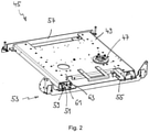
- an in figure 2 extraction device 45 shown in detail for the bottom labeller 43 is provided in order to pull out the bottom labeller 43 from the less accessible operating position below the conveyor belt 27, 29.
- the bottom labeler 43 also stands on a turntable 47 of the pull-out device 45. This makes it possible to pivot the bottom labeler 43 about the vertical in order to further facilitate work, in particular maintenance work, on the bottom labeler 43.
- the extension device 45 comprises a plate-shaped extension 49, which can be moved linearly via an extension guide 51 between a retracted end position, as shown in FIGS 1 and 2 is shown, and an extended end position, not shown, is mounted on a stationary pull-out support 53, which is fixedly connected to the frame 25.
- the pull-out support 53 has two L-shaped cross members 55, the shorter legs of which are each oriented in the vertical and the longer legs of which are each oriented in the horizontal.
- the two crossbeams 55 are arranged on both sides of the pull-out device 45 .
- the pull-out support 53 has two longitudinal supports 57, by means of which the two cross supports 55 are firmly connected to one another.
- the pull-out guide 51 is designed as a roller guide.
- two rollers 59 are provided on the top of each of the two crossbeams 55, which are arranged one behind the other in the direction of travel of the extension 49 and of which in 2 only the front roller 59 is visible in each case.
- the rollers 59 are each designed in the manner of a cable roller, ie their running surfaces are each provided with a circumferential groove in the middle.
- the two rollers 59 of a respective cross member 55 interact with a respective guide rod 61 oriented in the direction of travel, which is attached via a respective web 63 to the underside of the extension 49 . The interaction takes place in such a way that the respective guide rod 61 engages in the grooves of the two respective rollers 59, so that the guide rod 61 can roll off the rollers 59 when the extension 49 is moved.
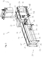
- an inventive labeling device 13 is shown, which compared to the known labeling device 13 according to the 1 and 2 further developed and their pull-out device 45 in the Figures 4a to 6b is explained in more detail, with the same reference numerals as in the preceding for the same parts 1 and 2 be used.
- the pull-out device 45 Compared to the known pull-out device, the pull-out device 45 according to the invention also has a motorized adjustment unit in the form of an electric motor drive 65 and a pneumatic cylinder 67, the respective function of which is explained in more detail below.
- the bottom labeller 43 does not stand directly on the turntable 47 but on a swivel extension 69 which in turn is attached to the turntable 47 .
- the electric motor drive 65 is provided for setting the retracted end position of the extension 49 . Since this position also determines the position of the bottom labeller 43 relative to the conveyor belt 27, 29 or the conveyor belt sections 27, 29, this ultimately also determines the label position on the packs.
- the pneumatic cylinder 67 is intended to move the extension 49 between the retracted end position and the extended end position.
- the electric motor drive 65 is arranged on the extension 49 and comprises a threaded spindle 75 which has a threaded rod 77 and a spindle nut 79, and an electric motor 81 which drives the threaded spindle 75 and the threaded rod 77, respectively.
- the threaded spindle 75 and the electric motor 81 are arranged in a housing 71 of the electric motor drive 65 which is fastened to the extension 49 via two fastening plates 73 . If the spindle nut 79 stationary held and the electric motor 81 activated, the threaded rod 77 moves with the electric motor 81 and the housing 71 in the axial direction of the threaded rod 77 and thus the extension 49 in the direction of travel (inward or outward).
- the threaded rod 77 is coupled to the housing 71 and thus to the extension 49 in an axially fixed manner.
- the extension 49 moves in the extension or retraction direction.
- the spindle nut 79 by means of the pneumatic cylinder 67, the extension 49 can be moved between the retracted end position and the extended end position.
- the electric motor drive 65 is controlled by a control device, not shown, which can be arranged in the switch cabinet 31 in particular.
- the control device can be used to ensure that the labels to be applied are applied to the incoming packs at a desired position, for example in the middle.
- respective dispensing positions are stored in a database (not shown) for various labels and/or packs that differ from one another in terms of their width, i.e. in particular their dimensions perpendicular to the direction of transport. If it is known which packs are to be provided with which labels, the control device can then select the appropriate dispensing position and set the position of the extract 49 accordingly.
- the pneumatic cylinder 67 is fixed in place on the rear side wall 33 via two fastening plates 83 .
- the pneumatic cylinder 67 comprises a housing 85 and a piston (not shown) which is arranged to be axially movable therein and to which a piston rod 87 protruding with one end out of the housing 85 is fastened.
- the pneumatic cylinder 67 is designed as a single-acting cylinder which can be operated with compressed air via a compressed air supply 89 so that the piston rod 87 can be moved back and forth in the axial direction.
- the piston rod 87 is via a connector 91 and a driver 93, which extends through a slot 95 formed on the underside of the housing 71 of the electric motor drive 65, is axially fixed to the spindle nut 79, so that actuation of the pneumatic cylinder 67 moves the extension 49 between the retracted end position and the extended end position can be proceeded as already mentioned above.
- an anti-extraction device 97 is provided in the form of a detachable magnetic coupling, by means of which the axially fixed coupling between the connecting element 91 and thus the piston or piston rod 87 on the one hand and the driver 93 and ultimately the statement 49 can be solved on the other hand, if the statement 49 drives against an operator.
- the magnetic coupling 97 has a permanent magnet 99, which magnetically attracts and pulls the driver 93 along during extension, with the magnetic attraction breaking off when the extension 49 encounters an obstacle.
- the operating pressure of the pneumatic cylinder 67 is selected to be comparatively low, e.g. 1.5 bar, so that the pneumatic cylinder 67 only exerts a comparatively small force.
- a retraction safety device 101 is also provided in order to prevent the operator from getting trapped and thus injured when the pull-out 49 is being retracted.
- the retraction safety device 101 includes that the threaded rod 77 is coupled to the electric motor 81 in an axially movable manner and the threaded rod 77 can actuate a safety switch 105 against the force of a coil spring 103 and through an opening in an inner wall of the housing 71 .
- the piston rod 87 is retracted into the housing 85 of the pneumatic cylinder 67.
- the connecting element 91 presses against the driver 93, so that the extract 49 mediated by the spindle nut 79, the threaded rod 77 and the housing 71 is moved into the retracted end position. If the extension 49 hits an obstacle, the axial coupling between the threaded rod 77 and the housing 71 is released. The spindle nut 79 moves in further, whereby the movement of the extension 49 and thus of the housing 71 is blocked, which results in an axial movement of the threaded rod 77 in the extension direction (with simultaneous rotary movement), whereby the safety switch 105 is actuated, so that the pneumatic cylinder 67 can be deactivated accordingly.
Landscapes
- Labeling Devices (AREA)
Abstract
Description
- Die vorliegende Erfindung betrifft eine Etikettiervorrichtung mit einem Förderband zum Transportieren von Packungen, insbesondere entlang einer Transportrichtung, einem Etikettierer, insbesondere für die Packungsunterseite, um Etiketten von unten auf die Packungen aufzubringen, und einer Auszugvorrichtung, die einen Auszug umfasst, der über eine Auszugführung an einem stationären Auszugträger gelagert und relativ zu diesem linear zwischen einer eingefahrenen Endposition und einer ausgefahrenen Endposition, insbesondere quer, insbesondere senkrecht, zur Förderrichtung, verfahrbar ist, wobei der Etikettierer auf dem Auszug positioniert ist, und wobei die Auszugvorrichtung derart ausgebildet ist, dass die Lage der eingefahrenen Endposition des Auszugs, insbesondere in Verfahrrichtung, einstellbar ist.
- Eine derartige Etikettiervorrichtung ist aus dem Dokument
DE 10 2013 203 456 A1 bekannt. Ohne Auszug sind Etikettierer für die Packungsunterseite aufgrund ihrer Anordnung unterhalb des Förderbands nur schwer zugänglich, so dass die Bedienung und Wartung derartiger Etikettierer erschwert wird. Durch den Auszug hingegen kann der Etikettierer ohne größere Probleme aus seiner Betriebsposition unterhalb des Förderbands in eine besser zugängliche Serviceposition verbracht bzw. bewegt werden. Das Verfahren des Auszugs erfolgt manuell und wird durch die Auszugführung ermöglicht. - Darüber hinaus kann über die Lage der eingefahrenen Endposition, die der Betriebsposition des Etikettierers entspricht, die Etikettenposition an den zu etikettierenden Packungen eingestellt werden. Beispielsweise kann die Lage der eingefahrenen Endposition verstellt werden, um von einer mittigen Anbringposition der Etiketten auf den Packungen auf eine außermittige Anbringposition zu wechseln. Darüber hinaus wird auch bei einer Umstellung der Etikettiervorrichtung auf Etiketten und/oder Packungen anderer Breite in der Regel eine Anpassung der Lage des Etikettierers erforderlich werden.
- Um die Lage der eingefahrenen Endposition und damit des Etikettierers einzustellen, ist dem Dokument
DE 10 2013 203 456 A1 ein in Verfahrrichtung verstellbarer Stopper für den Auszug vorgesehen. Der Stopper ist nach oben ausgerichtet und auf einer Schiene befestigt, die über Schraubverbindungen entlang in einem Querträger des Auszugträgers ausgebildeter Langlöcher in Verfahrrichtung verstellbar ist, wobei bei angezogenen Schraubverbindungen die Schiene an dem Querträger verklemmt ist. Ferner ist an dem beim Einfahren nachlaufenden Ende des Auszugs ein nach unten gerichtetes Anschlagelement unverstellbar befestigt, das in der eingefahrenen Endposition an dem Stopper anliegt. - Bei der Etikettiervorrichtung des Dokuments
DE 10 2013 203 456 A1 ist demnach zwar der Etikettierer an sich einfach und komfortabel zugänglich, jedoch nicht die Einrichtung, um die Lage der eingefahrenen Endposition des Auszugs einzustellen, so dass die Bedienung dieser Einstelleinrichtung erschwert wird. - Der Erfindung liegt die Aufgabe zugrunde, eine Etikettiervorrichtung der eingangs genannten Art anzugeben, die eine unproblematischere Einstellung der Lage der eingefahrenen Endposition des Auszugs ermöglicht.
- Die Aufgabe wird durch eine Etikettiervorrichtung mit den Merkmalen des Anspruchs 1 gelöst, und insbesondere dadurch, dass die Auszugvorrichtung eine, insbesondere von einer Steuerungseinrichtung gesteuerte, motorische Verstelleinheit, insbesondere einen Elektromotorantrieb, umfasst, um die Lage der eingefahrenen Endposition des Auszugs einzustellen.
- Erfindungsgemäß wird also nicht die Zugänglichkeit zu einer Einstelleinrichtung, wie sie aus dem Stand der Technik bekannt ist, verbessert, sondern es wird ein völlig anderer Ansatz gewählt, nämlich eine motorische Verstelleinheit vorzusehen, um die Lage des Auszugs in der eingefahrenen Endposition einzustellen. Eine Zugänglichkeit für einen Bediener ist dabei überhaupt nicht erforderlich.
- Die Auszugführung und der Auszugträger sind jeweils Teil der Auszugvorrichtung. Insbesondere ist der Auszug in der Horizontalen und/oder zumindest im Wesentlichen senkrecht zu einer Transportrichtung des Förderbands verfahrbar. Insbesondere ist der Etikettierer unterhalb des Förderbands und/oder innerhalb eines Gestells der Etikettiervorrichtung angeordnet. Insbesondere ist die motorische Verstelleinheit nicht dazu ausgelegt, den Auszug in die ausgefahrene Endposition zu verfahren. Insbesondere ist, insbesondere in einem Normalbetrieb der Etikettiervorrichtung, ein Verfahren des Auszugs über die Endpositionen hinaus nicht möglich. Insbesondere kann es sich bei den Packungen um Verpackungen handeln.
- Insbesondere ist eine Steuerungseinrichtung vorgesehen, die dazu ausgebildet ist, die motorische Verstelleinheit der Auszugvorrichtung derart anzusteuern, dass die Lage der eingefahrenen Endposition des Auszugs in Abhängigkeit von einer vorgegebenen Spendeposition der aufzubringenden Etiketten relativ zu dem Förderband insbesondere automatisch eingestellt wird.
- Die Spendeposition kann beispielsweise durch eine entsprechende Eingabe vorgegeben werden. Zusätzlich oder alternativ kann jedoch auch eine Speichereinrichtung vorgesehen sein, in der mehrere Spendepositionen für Etiketten und/oder Packungen unterschiedlicher Abmessung, insbesondere Breite, hinterlegt sind, wobei die Steuerungseinheit dazu ausgelegt ist, aus den hinterlegten Spendepositionen die vorgegebene Spendeposition auszuwählen.
- Nach einer Ausführungsform umfasst die motorische Verstelleinheit eine Gewindespindel, insbesondere mit einer Gewindestange und einer Spindelmutter, und einen die Gewindespindel antreibenden Elektromotor. Eine derartige motorische Verstelleinheit ist einfach umsetzbar und erlaubt eine genaue Einstellung der Lage der eingefahren Endposition des Auszugs. Üblicherweise wird die Steigung der Gewindespindel vergleichsweise klein gewählt sein, um eine Feineinstellung der Lage der eingefahrenen Endposition zu ermöglichen. Ein Verfahren des Auszugs zwischen der eingefahrenen Endposition und der ausgefahrenen Endposition hingegen kann aufgrund eines entsprechenden Verfahrens der Spindelmutter erfolgen. Insbesondere kann der Elektromotor fest auf dem Auszug angeordnet sein, so dass er bei einem Einstellen der Lage der eingefahrenen Endposition und bei einem Verfahren zwischen der eingefahrenen Endposition und der ausgefahrenen Endposition mit dem Auszug verfahren wird. Selbiges gilt für ein Gehäuse der motorischen Verstelleinheit.
- Vorzugsweise ist der Auszug, insbesondere über ein Gehäuse der motorischen Verstelleinheit, mit der Gewindestange axialfest gekoppelt, so dass bei ortsfest gehaltener Spindelmutter und bei aktiviertem Elektromotor eine axiale Bewegung der Gewindestange und damit des Auszugs erfolgt. Wird also der Elektromotor eingeschaltet, so dass sich die Gewindestange dreht, und wird dabei gleichzeitig die Spindelmutter ortsfest gehalten, resultiert hieraus zwangsweise eine Bewegung der Gewindestange in ihrer axialen Richtung. Da der Auszug mit der Gewindestange axialfest gekoppelt ist, resultiert eine axiale Bewegung der Gewindestange zwangsweise in einer entsprechenden Bewegung des Auszugs.
- Dabei kann eine Einfahrsicherung vorgesehen sein, die die axialfeste Kopplung des Auszugs mit der Gewindestange löst, wenn bei einem automatisierten Einfahren von der ausgefahrenen Endposition in die eingefahrene Endposition, insbesondere aufgrund eines entsprechenden Verfahrens der Spindelmutter, eine auf den Auszug einwirkende, dem Einfahren entgegenwirkende Kraft ein vorgegebenes Maß überschreitet. Dies kann beispielsweise dann der Fall sein, wenn ein Arm oder eine Hand eines Bedieners bei einem Einfahren des Auszugs versehentlich zwischen dem Auszug und einem Gestell der Etikettiervorrichtung eingeklemmt wird. Durch die Einfahrsicherung können somit Verletzungen des Bedieners zumindest weitgehend vermieden werden.
- Die Einfahrsicherung kann auf eine einfache und sichere Weise dadurch realisiert werden, dass die Gewindestange mit dem Elektromotor zwar drehfest, jedoch axialbeweglich gekoppelt ist, wobei die Gewindestange bei Überschreitung des vorgegebenen Maßes, gegen die Kraft einer Feder einen Sicherheitsschalter betätigt. Durch den Sicherheitsschalter kann dann ein automatisiertes Einfahren, insbesondere aufgrund eines weiteren Antriebs, wie er nachstehend näher erläutert ist, abgeschaltet werden.
- Wie vorstehend erwähnt, kann die Auszugvorrichtung einen weiteren, insbesondere von einer Steuerungseinrichtung gesteuerten, Antrieb umfassen, um den Auszug zwischen der eingefahrenen Endposition und der ausgefahrenen Endposition automatisiert, d.h. nicht manuell, zu verfahren. Bevorzugt ist der weitere Antrieb als ein Pneumatik- oder Hydraulikzylinder, insbesondere mit einem ortsfest angeordnetem Gehäuse und einem darin axial beweglich angeordneten Kolben, ausgebildet. Der Betriebsdruck des Pneumatikzylinders beträgt dabei bevorzugt maximal 3 bar, insbesondere maximal 2 bar. Bei diesen, vergleichsweise geringen Drücken können Verletzungen des Bedieners durch Einklemmen bei einem Einfahren des Auszugs ebenfalls zumindest weitgehend vermieden werden. Insbesondere kann die vorgenannte Spindelmutter mit dem Kolben axialfest gekoppelt sein, so dass bei aktiviertem weiteren Antrieb eine axiale Bewegung der motorische Verstelleinheit und damit des Auszugs erfolgt. Insbesondere ermöglicht das Vorsehen des weiteren Antriebs ein schnelles Verfahren des Auszugs zwischen der eingefahrenen Endposition und der ausgefahrenen Endposition, wohingegen das Verfahren des Auszugs beim Einstellen der Lage der eingefahrenen Endposition durch die motorische Verstelleinheit, insbesondere durch eine entsprechend geringe Steigung der vorgenannten Gewindespindel, um eine Feineinstellung dieser Lage zu ermöglichen, vergleichsweise langsam erfolgt. Insbesondere erfolgt das Verfahren des Auszugs zwischen der eingefahrenen Endposition und der ausgefahrenen Endposition mit einer höheren Geschwindigkeit als das Verfahren des Auszugs beim Einstellen der Lage der eingefahrenen Endposition. Grundsätzlich ist es auch möglich, dass alternativ oder zusätzlich der Auszug als Handauszug ausgebildet ist, um den Auszug manuell zwischen der eingefahrenen Endposition und der ausgefahrenen Endposition zu verfahren.
- Darüber hinaus kann eine Ausfahrsicherung vorgesehen sein, die die axialfeste Kopplung der Spindelmutter mit dem Kolben löst, wenn bei einem Ausfahren von der eingefahrenen Endposition in die ausgefahrene Endposition, insbesondere aufgrund eines entsprechenden Verfahrens des Kolbens, eine auf den Auszug einwirkende, dem Ausfahren entgegenwirkende Kraft ein vorgegebenes Maß überschreitet. Dies kann beispielsweise dann der Fall sein, wenn ein Bediener einem Ausfahren des Auszugs im Weg steht. Durch die Ausfahrsicherung können somit Verletzungen des Bedieners zumindest weitgehend vermieden werden.
- Die Ausfahrsicherung kann auf eine einfache und sichere Weise dadurch realisiert werden, dass die Kopplung der Spindelmutter mit dem Kolben eine Magnetkopplung zwischen einem Magneten und einem Mitnehmer umfasst, wobei bei Überschreitung des vorgegebenen Maßes die Magnetkopplung löst.
- Insbesondere umfasst das Förderband zwei, insbesondere in Transportrichtung, hintereinander und voneinander beabstandet angeordnete Förderbandabschnitte, so dass zwischen den beiden Förderbandabschnitten ein Spalt ausgebildet ist, durch den die Etiketten von unten auf die Packungen aufbringbar sind. Insbesondere erstreckt sich der Spalt über die gesamte Breite des Förderbands, so dass auch besonders breite Etiketten und/oder an jeder Stelle Etiketten auf die Packungen aufbringbar sind.
- Die Erfindung betrifft ferner eine Wäge-Fördervorrichtung mit wenigstens einem Förderband, einem Wägeband und einer Etikettiervorrichtung, wie sie vorstehend beschrieben ist.
- Weitere vorteilhafte Ausgestaltungen der Erfindung sind in den abhängigen Ansprüchen, der weiteren Beschreibung und der Zeichnung beschrieben.
- Die Erfindung wird im Folgenden beispielhaft unter Bezugnahme auf die Zeichnung beschrieben. Es zeigen,
- Fig. 1
- eine perspektivische Ansicht einer Wäge-Fördervorrichtung mit einer Etikettiervorrichtung mit einer Auszugvorrichtung gemäß dem Stand der Technik,
- Fig. 2
- die Auszugvorrichtung aus
Fig. 1 in einer perspektivischen Ansicht, - Fig. 3
- eine erfindungsgemäße Etikettiervorrichtung, die eine Auszugvorrichtung mit einem Auszug, einem Elektromotorantrieb und einem Pneumatikzylinder, und einen auf dem Auszug angeordneten Etikettierer für die Packungsunterseite umfasst,
- Fig. 4a, b
- die Auszugvorrichtung aus
Fig. 3 in zwei perspektivischen Ansichten, - Fig. 5
- die Auszugvorrichtung aus
Fig. 3 in einer Ansicht von oben, - Fig. 6a
- eine Detail-Ansicht des Elektromotorantriebs und des Pneumatikzylinders, wobei Gehäuseteile des Elektromotorantriebs weggelassen wurden, und
- Fig. 6b
- die Darstellung gemäß
Fig. 6 , wobei zusätzlich der Pneumatikzylinder weggelassen wurde. - Die in
Fig. 1 dargestellte Vorrichtung zeigt eine aus dem eingangs genannten Dokument bekannte Wäge-Fördervorrichtung 11, die ein Zuführband 15, ein Wägeband 17, ein Abführband 19, einen Metalldetektor 23 und eine Etikettiervorrichtung 13 mit ein Förderband mit zwei Förderbandabschnitten 27, 29 umfasst. Das Wägeband 17 ist mit einer unterhalb des Wägebands 17 angeordneten, nicht dargestellten Wägezelle gekoppelt, die dazu ausgelegt ist, das Gewicht einer sich über das Wägeband 17 bewegenden Packung zu bestimmen. Wägeband 17 und Wägezelle bilden eine Wägeplattform, die als Kontrollwaage bzw. Checkweigher oder als Preisauszeichner ausgebildet sein kann. Zu beiden Seiten der drei Transportbänder 15, 17, 19 sind Schmutzabweisbleche 21 vorgesehen. - In einem Normalbetrieb der Wäge-Fördervorrichtung 11 werden zu verwiegende Packungen von dem Zuführband 15 an das Wägeband 17 übergeben, dort gewogen und über das Abführband 19 an ein Transportband des Metalldetektors 23 weitertransportiert. Anschließend werden die Packungen von der Etikettiervorrichtung 13 übernommen und mit einem Etikett versehen, das bei einem Preisauszeichner zuvor mit dem von der Wägezelle für die jeweilige Packung ermittelten Gewicht bedruckt wurde. Bei der Etikettiervorrichtung 13 handelt es sich demnach um eine Etikettiervorrichtung einschließlich Drucker. Der Metalldetektor 23 kann auch weggelassen werden, oder anstelle des Metalldetektors 23 oder zusätzlich hierzu kann auch beispielsweise eine Sortiereinrichtung vorgesehen sein. Im Bereich der Etikettiervorrichtung 13 ist in der Ansicht gemäß
Fig. 1 an der Rückseite eines Gestells 25 der Wäge-Fördervorrichtung 11 ein Schaltschrank 31 für die Steuerung der Wäge-Fördervorrichtung 11 vorgesehen. - Das Gestell 25 umfasst mehrere Seitenwangen 33, die im Bereich der Förderbänder 15 und 19, des Wägebands 17 und des Metalldetektors 23, d.h. im Bereich eines Wägemoduls und eines Metalldetektormoduls des Gestells 25, über jeweils mehrere als Rundrohre ausgebildete, parallel zueinander verlaufende Längsträger 37 fest miteinander verbunden sind. Die Seitenwangen 33 des Wägemoduls sind jeweils zweiteilig ausgebildet, wobei die beiden jeweiligen Seitenwangenteile über als Vierkantrohre ausgebildete Querträger 39, die an den Innenseiten der Seitenwangenteile vorgesehen sind, miteinander verbunden sind. An die Seitenwangen 33 sind jeweils zwei Standfüße 35 angeschraubt, die unabhängig voneinander höhenverstellbar sind. Durch die Standfüße 35 kann eine Justierung der Höhe des Gestells 25 vorgenommen werden.
- Die Etikettiervorrichtung 13 umfasst einen sogenannten Top-Etikettierer 41 bzw. Etikettierer für die Packungsoberseite, der oberhalb des Förderbands 27, 29 bzw. der Förderbandabschnitte 27, 29 angeordnet ist, um auf dem Förderband 27, 29 transportierte Packungen von oben, d.h. an deren Oberseite, mit einem Etikett zu versehen. Darüber hinaus umfasst die Etikettiervorrichtung 13 einen sogenannten Bottom-Etikettierer 43 bzw. Etikettierer für die Packungsunterseite, der innerhalb des Gestells 25, unterhalb des Förderbands 27, 29 bzw. der Förderbandabschnitte 27, 29 angeordnet ist, um auf dem Förderband 27, 29 transportierte Packungen von unten, d.h. an deren Unterseite, mit einem Etikett zu versehen. Hierzu wird das jeweilige Etikett von dem Bottom-Etikettierer 43 nach oben durch den zwischen dem Förderbandabschnitt 27 und dem Förderbandabschnitt 29 ausgebildeten Spalt hindurch gespendet und auf den Packungen appliziert.
- Um eine einfache Zugänglichkeit zu dem Bottom-Etikettierer 43 zu gewährleisten, beispielsweise für einen Etikettenrollenwechsel oder eine Wartung, ist eine in
Fig. 2 im Detail gezeigte Auszugvorrichtung 45 für den Bottom-Etikettierer 43 vorgesehen, um den Bottom-Etikettierer 43 aus der wenig zugänglichen Betriebsposition unterhalb des Förderbands 27, 29 herauszuziehen. Der Bottom-Etikettierer 43 steht dabei zusätzlich auf einem Drehteller 47 der Auszugvorrichtung 45. Hierdurch ist es möglich, den Bottom-Etikettierer 43 um die Vertikale zu schwenken, um Arbeiten, insbesondere Wartungsarbeiten, am Bottom-Etikettierer 43 weiter zu erleichtern. - Die Auszugvorrichtung 45 umfasst einen plattenförmigen Auszug 49, der über eine Auszugführung 51 linear verfahrbar zwischen der einer eingefahrenen Endposition, wie sie in den
Fig. 1 und2 dargestellt ist, und einer nicht dargestellten ausgefahrenen Endposition an einem stationären Auszugträger 53, der fest mit dem Gestell 25 verbunden ist, gelagert ist. Der Auszugträger 53 weist zwei L-förmige Querträger 55 auf, deren kürzerer Schenkel jeweils in der Vertikalen und deren längerer Schenkel jeweils in der Horizontalen orientiert sind. Die beiden Querträger 55 sind zu den beiden Seiten der Auszugvorrichtung 45 angeordnet. Darüber hinaus weist der Auszugträger 53 zwei Längsträger 57 auf, durch die die beiden Querträger 55 fest miteinander verbunden sind. - Die Auszugführung 51 ist als Rollenführung ausgebildet. Hierzu sind auf jedem der beiden Querträger 55 oberseitig jeweils zwei Rollen 59 vorgesehen, die in Verfahrrichtung des Auszugs 49 hintereinander angeordnet sind und von denen in
Fig. 2 jeweils lediglich die vordere Rolle 59 sichtbar ist. Die Rollen 59 sind jeweils nach Art einer Seilrolle ausgebildet, d.h. ihre Laufflächen sind jeweils mittig mit einer umlaufenden Nut versehen. Die beiden Rollen 59 eines jeweiligen Querträgers 55 wirken mit einer jeweiligen in Verfahrrichtung orientierten Führungsstange 61 zusammen, die über einen jeweiligen Steg 63 jeweils an der Unterseite des Auszugs 49 angebracht ist. Das Zusammenwirken erfolgt dabei derart, dass die jeweilige Führungsstange 61 in die Nuten der beiden jeweiligen Rollen 59 eingreift, so dass die Führungsstange 61 beim Verfahren des Auszugs 49 an den Rollen 59 abrollen kann. - In
Fig. 3 ist eine erfindungsgemäße Etikettiervorrichtung 13 dargestellt, die gegenüber der bekannten Etikettiervorrichtung 13 gemäß denFig. 1 und2 weitergebildet und deren Auszugsvorrichtung 45 in denFig. 4a bis 6b näher erläutert ist, wobei für gleiche Teile gleiche Bezugszeichen wie in den vorangegangenenFig. 1 und2 verwendet werden. - Die erfindungsgemäße Auszugsvorrichtung 45 weist gegenüber der bekannten Auszugsvorrichtung zusätzlich eine motorische Verstelleinheit in Form eines Elektromotorantriebs 65 sowie einen Pneumatikzylinder 67 auf, deren jeweilige Funktion nachstehend näher erläutert wird. Darüber hinaus steht der Bottom-Etikettierer 43 nicht unmittelbar auf dem Drehteller 47, sondern auf einer Schwenkverlängerung 69, die ihrerseits auf dem Drehteller 47 befestigt ist.
- Der Elektromotorantrieb 65 ist dafür vorgesehen, die Lage der eingefahrenen Endposition des Auszugs 49 einzustellen. Da durch diese Lage auch die Lage des Bottom-Etikettierers 43 relativ zu dem Förderband 27, 29 bzw. den Förderbandabschnitten 27, 29 vorgegeben ist, ist hierdurch letztlich auch die Etikettenposition an den Packungen vorgegeben. Der Pneumatikzylinder 67 hingegen ist dafür vorgesehen, den Auszug 49 zwischen der eingefahrenen Endposition und der ausgefahrenen Endposition zu verfahren.
- Der Elektromotorantrieb 65 ist auf dem Auszug 49 angeordnet und umfasst eine Gewindespindel 75, die eine Gewindestange 77 und eine Spindelmutter 79 aufweist, und einen Elektromotor 81, der die Gewindespindel 75 bzw. die Gewindestange 77 antreibt. Die Gewindespindel 75 und der Elektromotor 81 sind in einem Gehäuse 71 des Elektromotorantriebs 65 angeordnet, das über zwei Befestigungsbleche 73 an dem Auszug 49 befestigt ist. Wird die Spindelmutter 79 ortsfest gehalten und der Elektromotor 81 aktiviert, bewegt sich die Gewindestange 77 mit dem Elektromotor 81 und dem Gehäuse 71 in axialer Richtung der Gewindestange 77 und damit der Auszug 49 in Verfahrrichtung (einwärts oder auswärts). Hierzu ist die Gewindestange 77 mit dem Gehäuse 71 und damit mit dem Auszug 49 axialfest gekoppelt. Abhängig von der Drehrichtung des Elektromotors 81 bewegt sich der Auszug 49 in ein- oder Ausfahrrichtung. Darüber hinaus kann durch Verfahren der Spindelmutter 79 mittels des Pneumatikzylinders 67 der Auszug 49 zwischen der eingefahrenen Endposition und der ausgefahrenen Endposition verfahren werden.
- Der Elektromotorantrieb 65 wird durch eine nicht dargestellte Steuerungseinrichtung gesteuert, die insbesondere in dem Schaltschrank 31 angeordnet sein kann. Über die Steuerungseinrichtung kann erreicht werden, dass die aufzubringenden Etiketten an einer gewünschten Position, beispielsweise mittig, an den einlaufenden Packungen appliziert werden. Insbesondere sind in einer nicht dargestellten Datenbank für verschiedene Etiketten und/oder Packungen, die sich in ihrer Breite, d.h. insbesondere in ihrer Abmessung senkrecht zur Transportrichtung, voneinander unterscheiden, jeweilige Spendepositionen hinterlegt. Bei Kenntnis, welche Packungen mit welchen Etiketten versehen werden sollen, kann die Steuerungseinrichtung dann die entsprechende Spendeposition auswählen und die Lage des Auszugs 49 entsprechend einstellen.
- Der Pneumatikzylinder 67 ist über zwei Befestigungsbleche 83 an der hinteren Seitenwange 33 ortsfest befestigt. Der Pneumatikzylinder 67 umfasst ein Gehäuse 85 und einen darin axial beweglich angeordneten, nicht dargestellten Kolben, an dem eine mit einem Ende aus dem Gehäuse 85 herausstehende Kolbenstange 87 befestigt ist. Der Pneumatikzylinder 67 ist in der dargestellten Ausführungsform als einfachwirkender Zylinder ausgebildet, der über eine Druckluftversorgung 89 mit Druckluft betreibbar ist, so dass die Kolbenstange 87 in axialer Richtung hin- und her bewegt werden kann. Die Kolbenstange 87 ist über ein Verbindungselement 91 und einen Mitnehmer 93, der sich durch einen an der Unterseite des Gehäuses 71 des Elektromotorantriebs 65 ausgebildeten Schlitz 95 hindurch erstreckt, mit der Spindelmutter 79 axialfest gekoppelt, so dass durch Betätigung des Pneumatikzylinders 67 der Auszug 49 zwischen der eingefahrenen Endposition und der ausgefahrenen Endposition verfahren werden kann, wie es bereits vorstehend erwähnt wurde.
- Darüber hinaus ist eine Ausfahrsicherung 97 in Form einer lösbaren Magnetkopplung vorgesehen, durch die beim Ausfahren des Auszugs 49 aus der eingefahrenen Endposition in die ausgefahrene Endposition die axialfeste Kopplung zwischen dem Verbindungselement 91 und damit dem Kolben bzw. der Kolbenstange 87 einerseits und dem Mitnehmer 93 und letztlich dem Auszug 49 andererseits gelöst werden kann, falls der Auszug 49 gegen einen Bediener fährt. Hierdurch können Verletzungen vermieden werden. Die Magnetkopplung 97 weist hierzu einen Permanentmagneten 99 auf, der den Mitnehmer 93 magnetisch an- und beim Ausfahren mitzieht, wobei die magnetische Anziehung abreißt, wenn der Auszug 49 auf ein Hindernis trifft. Alternativ oder zusätzlich kann als eine Sicherheitseinrichtung auch vorgesehen sein, dass der Betriebsdruck des Pneumatikzylinders 67 vergleichsweise gering gewählt wird, z.B. 1,5 bar, so dass durch den Pneumatikzylinder 67 lediglich eine vergleichsweise geringe Kraft ausgeübt wird.
- Ferner ist auch eine Einfahrsicherung 101 vorgesehen, um beim Einfahren des Auszugs 49 ein Einklemmen und damit eine Verletzung eines Bedieners zu vermeiden. Die Einfahrsicherung 101 umfasst, dass die Gewindestange 77 mit dem Elektromotor 81 axialbeweglich gekoppelt ist und die Gewindestange 77 gegen die Kraft einer Schraubenfeder 103 und durch eine Öffnung in einer inneren Wand des Gehäuses 71 hindurch einen Sicherheitsschalter 105 betätigen kann. Zum Einfahren des Auszugs 49 wird die Kolbenstange 87 in das Gehäuse 85 des Pneumatikzylinders 67 zurückgezogen. Hierbei drückt das Verbindungselement 91 gegen den Mitnehmer 93, so dass der Auszug 49 unter Vermittlung der Spindelmutter 79, der Gewindestange 77 und des Gehäuses 71 in die eingefahrene Endposition verfahren wird. Stößt der Auszug 49 dabei auf ein Hindernis, wird die axiale Kopplung zwischen der Gewindestange 77 und dem Gehäuse 71 gelöst. Hierbei fährt die Spindelmutter 79 weiter ein, wobei die Bewegung des Auszugs 49 und damit des Gehäuses 71 jedoch blockiert ist, woraus (bei gleichzeitiger Drehbewegung) eine axiale Bewegung der Gewindestange 77 in Ausfahrrichtung resultiert, wodurch der Sicherheitsschalter 105 betätigt wird, so dass der Pneumatikzylinder 67 entsprechend deaktiviert werden kann.
-
- 11
- Wäge-Fördervorrichtung
- 13
- Etikettiervorrichtung
- 15
- Zuführband
- 17
- Wägeband
- 19
- Abführband
- 21
- Schmutzabweisblech
- 23
- Metalldetektor
- 25
- Gestell
- 27
- Förderbandabschnitt
- 29
- Förderbandabschnitt
- 31
- Schaltschrank
- 33
- Seitenwange
- 35
- Standfuß
- 37
- Längsträger
- 39
- Querträger
- 41
- Top-Etikettierer
- 43
- Bottom-Etikettierer
- 45
- Auszugvorrichtung
- 47
- Drehteller
- 49
- Auszug
- 51
- Auszugführung
- 53
- Auszugträger
- 55
- Querträger
- 57
- Längsträger
- 59
- Rolle
- 61
- Führungsstange
- 63
- Steg
- 65
- Elektromotorantrieb
- 67
- Pneumatikzylinder
- 69
- Schwenkverlängerung
- 71
- Gehäuse
- 73
- Befestigungsblech
- 75
- Gewindespindel
- 77
- Gewindestange
- 79
- Spindelmutter
- 81
- Elektromotor
- 83
- Befestigungsblech
- 85
- Gehäuse
- 87
- Kolbenstange
- 89
- Druckluftversorgung
- 91
- Verbindungselement
- 93
- Mitnehmer
- 95
- Schlitz
- 97
- Ausfahrsicherung
- 99
- Permanentmagnet
- 101
- Einfahrsicherung
- 103
- Schraubenfeder
- 105
- Sicherheitsschalter
- 107
- Spalt
Claims (14)
- Etikettiervorrichtung (13) mit einem Förderband (27, 29) zum Transportieren von Packungen, einem Etikettierer (43), um Etiketten von unten auf die Packungen aufzubringen, und einer Auszugvorrichtung (45), die einen Auszug (49) umfasst, der über eine Auszugführung (51) an einem stationären Auszugträger (53) gelagert und relativ zu diesem linear zwischen einer eingefahrenen Endposition und einer ausgefahrenen Endposition verfahrbar ist, wobei der Etikettierer (43) auf dem Auszug (49) positioniert ist, und wobei die Auszugvorrichtung (45) derart ausgebildet ist, dass die Lage der eingefahrenen Endposition des Auszugs (49) einstellbar ist,
dadurch gekennzeichnet, dass
die Auszugvorrichtung (45) eine motorische Verstelleinheit (65) umfasst, um die Lage der eingefahrenen Endposition des Auszugs (49) einzustellen, und eine Steuerungseinrichtung vorgesehen ist, die dazu ausgebildet ist, die motorische Verstelleinheit (65) der Auszugvorrichtung (45) derart anzusteuern, dass die Lage der eingefahrenen Endposition des Auszugs (49) in Abhängigkeit von einer vorgegebenen Spendeposition der aufzubringenden Etiketten relativ zu dem Förderband (27, 29) eingestellt wird. - Etikettiervorrichtung nach Anspruch 1,
dadurch gekennzeichnet, dass
eine Speichereinrichtung vorgesehen ist, in der mehrere Spendepositionen für Etiketten und/oder Packungen unterschiedlicher Abmessung, insbesondere Breite, hinterlegt sind, wobei die Steuerungseinheit dazu ausgelegt ist, aus den hinterlegten Spendepositionen die vorgegebene Spendeposition auszuwäh len. - Etikettiervorrichtung nach zumindest einem der vorstehenden Ansprüche, dadurch gekennzeichnet, dass
die motorische Verstelleinheit (65) eine Gewindespindel (75), insbesondere mit einer Gewindestange (77) und einer Spindelmutter (79), und einen die Gewindespindel (75) antreibenden Elektromotor (81) umfasst, wobei bevorzugt ein Verfahren des Auszugs (49) zwischen der eingefahrenen Endposition und der ausgefahrenen Endposition aufgrund eines entsprechenden Verfahrens der Spindelmutter (79) erfolgt. - Etikettiervorrichtung nach Anspruch 3,
dadurch gekennzeichnet, dass
der Auszug (49), insbesondere über ein Gehäuse (71) der motorischen Verstelleinheit (65), mit der Gewindestange (77) axialfest gekoppelt ist, so dass bei ortsfest gehaltener Spindelmutter (79) und bei aktiviertem Elektromotor (81) eine axiale Bewegung der Gewindestange (77) und damit des Auszugs (49) erfolgt. - Etikettiervorrichtung nach Anspruch 4,
dadurch gekennzeichnet, dass
eine Einfahrsicherung (101) vorgesehen ist, die die axialfeste Kopplung des Auszugs (49) mit der Gewindestange (77) löst, wenn bei einem automatisierten Einfahren von der ausgefahrenen Endposition in die eingefahrene Endposition, insbesondere aufgrund eines entsprechenden Verfahrens der Spindelmutter (79), eine auf den Auszug (49) einwirkende, dem Einfahren entgegenwirkende Kraft ein vorgegebenes Maß überschreitet. - Etikettiervorrichtung nach Anspruch 5,
dadurch gekennzeichnet, dass
die Einfahrsicherung (101) umfasst, dass die Gewindestange (77) mit dem Elektromotor (81) zwar drehfest, jedoch axialbeweglich gekoppelt ist, wobei die Gewindestange (77) bei Überschreitung des vorgegebenen Maßes, gegen die Kraft einer Feder (103) einen Sicherheitsschalter (105) betätigt. - Etikettiervorrichtung nach zumindest einem der vorstehenden Ansprüche, dadurch gekennzeichnet, dass
die Auszugvorrichtung (45) einen weiteren Antrieb (67) umfasst, um den Auszug (49) zwischen der eingefahrenen Endposition und der ausgefahrenen Endposition automatisiert zu verfahren. - Etikettiervorrichtung nach Anspruch 7,
dadurch gekennzeichnet, dass
der weitere Antrieb (67) als ein Pneumatik- oder Hydraulikzylinder, insbesondere mit einem ortsfest angeordnetem Gehäuse (85) und einem darin axial beweglich angeordneten Kolben, ausgebildet ist. - Etikettiervorrichtung nach Anspruch 8,
dadurch gekennzeichnet, dass
der Betriebsdruck des Pneumatikzylinders (67) maximal 3 bar, insbesondere maximal 2 bar, beträgt. - Etikettiervorrichtung nach Anspruch 8 oder 9,
dadurch gekennzeichnet, dass
eine Spindelmutter (79) einer Gewindespindel (75) der motorischen Verstelleinheit (65) mit dem Kolben axialfest gekoppelt ist, so dass bei aktiviertem weiteren Antrieb (67) eine axiale Bewegung der motorischen Verstelleinheit (65) und damit des Auszugs (49) erfolgt. - Etikettiervorrichtung nach Anspruch 10,
dadurch gekennzeichnet, dass
eine Ausfahrsicherung (97) vorgesehen ist, die die axialfeste Kopplung der Spindelmutter (79) mit dem Kolben löst, wenn bei einem Ausfahren von der eingefahrenen Endposition in die ausgefahrene Endposition, insbesondere aufgrund eines entsprechenden Verfahrens des Kolbens, eine auf den Auszug (49) einwirkende, dem Ausfahren entgegenwirkende Kraft ein vorgegebenes Maß überschreitet. - Etikettiervorrichtung nach Anspruch 11,
dadurch gekennzeichnet, dass
die Ausfahrsicherung (97) umfasst, dass die Kopplung der Spindelmutter (79) mit dem Kolben eine Magnetkopplung zwischen einem Magneten (99) und einem Mitnehmer (93) umfasst, wobei bei Überschreitung des vorgegebenen Maßes die Magnetkopplung löst. - Etikettiervorrichtung nach zumindest einem der vorstehenden Ansprüche, dadurch gekennzeichnet, dass
das Förderband (27, 29) zwei hintereinander und voneinander beabstandet angeordnete Förderbandabschnitte (27, 29) umfasst, so dass zwischen den beiden Förderbandabschnitten (27, 29) ein Spalt (107) ausgebildet ist, durch den die Etiketten von unten auf die Packungen aufbringbar sind. - Wäge-Fördervorrichtung (11) mit wenigstens einem Förderband (15, 17), einem Wägeband (19) und einer Etikettiervorrichtung (13) nach einem der vorstehenden Ansprüche.
Priority Applications (1)
| Application Number | Priority Date | Filing Date | Title |
|---|---|---|---|
| EP21191686.1A EP3950517B1 (de) | 2018-03-21 | 2018-03-21 | Etikettiervorrichtung |
Applications Claiming Priority (2)
| Application Number | Priority Date | Filing Date | Title |
|---|---|---|---|
| EP18163141.7A EP3543155B1 (de) | 2018-03-21 | 2018-03-21 | Etikettiervorrichtung |
| EP21191686.1A EP3950517B1 (de) | 2018-03-21 | 2018-03-21 | Etikettiervorrichtung |
Related Parent Applications (2)
| Application Number | Title | Priority Date | Filing Date |
|---|---|---|---|
| EP18163141.7A Division-Into EP3543155B1 (de) | 2018-03-21 | 2018-03-21 | Etikettiervorrichtung |
| EP18163141.7A Division EP3543155B1 (de) | 2018-03-21 | 2018-03-21 | Etikettiervorrichtung |
Publications (2)
| Publication Number | Publication Date |
|---|---|
| EP3950517A1 true EP3950517A1 (de) | 2022-02-09 |
| EP3950517B1 EP3950517B1 (de) | 2023-12-20 |
Family
ID=61749938
Family Applications (2)
| Application Number | Title | Priority Date | Filing Date |
|---|---|---|---|
| EP18163141.7A Active EP3543155B1 (de) | 2018-03-21 | 2018-03-21 | Etikettiervorrichtung |
| EP21191686.1A Active EP3950517B1 (de) | 2018-03-21 | 2018-03-21 | Etikettiervorrichtung |
Family Applications Before (1)
| Application Number | Title | Priority Date | Filing Date |
|---|---|---|---|
| EP18163141.7A Active EP3543155B1 (de) | 2018-03-21 | 2018-03-21 | Etikettiervorrichtung |
Country Status (2)
| Country | Link |
|---|---|
| US (1) | US10994885B2 (de) |
| EP (2) | EP3543155B1 (de) |
Citations (4)
| Publication number | Priority date | Publication date | Assignee | Title |
|---|---|---|---|---|
| GB2076549A (en) * | 1980-02-26 | 1981-12-02 | Teraoka Seikosho Kk | Weight measuring price computing and packing apparatus |
| GB2253829A (en) * | 1991-03-20 | 1992-09-23 | Berkel Ltd | Label applying apparatus |
| WO1993008081A1 (de) * | 1991-10-24 | 1993-04-29 | Bizerba-Werke Wilhelm Kraut Gmbh & Co. Kg | Vorrichtung zum aufbringen mehrerer etiketten |
| DE102013203456A1 (de) | 2013-02-28 | 2014-08-28 | Bizerba Gmbh & Co Kg | Etikettiervorrichtung |
Family Cites Families (1)
| Publication number | Priority date | Publication date | Assignee | Title |
|---|---|---|---|---|
| US4360381A (en) | 1980-04-11 | 1982-11-23 | Sumitomo Metal Industries, Ltd. | Ferritic stainless steel having good corrosion resistance |
-
2018
- 2018-03-21 EP EP18163141.7A patent/EP3543155B1/de active Active
- 2018-03-21 EP EP21191686.1A patent/EP3950517B1/de active Active
-
2019
- 2019-03-20 US US16/359,203 patent/US10994885B2/en active Active
Patent Citations (4)
| Publication number | Priority date | Publication date | Assignee | Title |
|---|---|---|---|---|
| GB2076549A (en) * | 1980-02-26 | 1981-12-02 | Teraoka Seikosho Kk | Weight measuring price computing and packing apparatus |
| GB2253829A (en) * | 1991-03-20 | 1992-09-23 | Berkel Ltd | Label applying apparatus |
| WO1993008081A1 (de) * | 1991-10-24 | 1993-04-29 | Bizerba-Werke Wilhelm Kraut Gmbh & Co. Kg | Vorrichtung zum aufbringen mehrerer etiketten |
| DE102013203456A1 (de) | 2013-02-28 | 2014-08-28 | Bizerba Gmbh & Co Kg | Etikettiervorrichtung |
Also Published As
| Publication number | Publication date |
|---|---|
| US20190291912A1 (en) | 2019-09-26 |
| EP3543155A1 (de) | 2019-09-25 |
| US10994885B2 (en) | 2021-05-04 |
| EP3543155B1 (de) | 2021-09-29 |
| EP3950517B1 (de) | 2023-12-20 |
Similar Documents
| Publication | Publication Date | Title |
|---|---|---|
| WO2010135756A1 (de) | Kommissioniereinrichtung | |
| DE3142378C2 (de) | ||
| EP3012196B1 (de) | Einrichtung zur anordnung eines kantenschutzmittels und vorrichtung zum umreifen von packstücken mit vorgenannter einrichtung | |
| EP1423231A1 (de) | Schraubstation | |
| EP2938544B1 (de) | Etikettiervorrichtung | |
| DE69305271T2 (de) | Siegelvorrichtung für Schachteln mit zwei übereinander angeordneten Siegeleinheiten und vereinfachtem Zugang zur unteren Siegeleinheit | |
| DE3525292C1 (de) | Kabeltrommelabroller | |
| EP3936446B1 (de) | Verfahren zum abtrennen von etiketten | |
| EP2157021B1 (de) | Etikettiermaschine | |
| EP3543155B1 (de) | Etikettiervorrichtung | |
| DE4428247B4 (de) | Transportvorrichtung für textile Packungen | |
| DE3710916A1 (de) | Vorrichtung zur fuehrung von paletten auf einer rollenbahn | |
| DE2948078A1 (de) | Vorrichtung an karden oder kaemmaschinen zum automatischen auswechseln der aufnahmebehaelter fuer das austretende textilgut | |
| DE1585882B1 (de) | Einschiebefaltvorrichtung | |
| DE19724378A1 (de) | Regal mit Entladevorrichtung | |
| EP3936288B1 (de) | Abschneider für selbstklebende trägerlose endlosband-etiketten | |
| EP1348664B1 (de) | Falzmaschine mit einer Seitenanschlageinrichtung | |
| EP0417476A1 (de) | Schnelleinzugseinrichtung für Werkstückträger | |
| DE3133028C2 (de) | Vorrichtung zur vereinzelten Entnahme blattförmiger Druckereierzeugnisse, insbesondere Zeitungen | |
| EP3463975B1 (de) | Abschiebevorrichtung und abschiebewagen mit einer abschiebevorrichtung | |
| EP0805109A1 (de) | Etikettiergerät | |
| DE3546815C2 (de) | ||
| DE20213989U1 (de) | Falzmaschine | |
| DE1652760C3 (de) | Für eine Tafelschere für Tafeln aus Blech, Kunststoff o.dgl. bestimmte Vorrichtung zum Unterstützen und Abfuhren der geschnittenen Tafeln | |
| WO2003084752A1 (de) | Vorrichtung zum positionieren von weiterverarbeitungseinrichtungen an druckmaschinen |
Legal Events
| Date | Code | Title | Description |
|---|---|---|---|
| PUAI | Public reference made under article 153(3) epc to a published international application that has entered the european phase |
Free format text: ORIGINAL CODE: 0009012 |
|
| STAA | Information on the status of an ep patent application or granted ep patent |
Free format text: STATUS: THE APPLICATION HAS BEEN PUBLISHED |
|
| AC | Divisional application: reference to earlier application |
Ref document number: 3543155 Country of ref document: EP Kind code of ref document: P |
|
| AK | Designated contracting states |
Kind code of ref document: A1 Designated state(s): AL AT BE BG CH CY CZ DE DK EE ES FI FR GB GR HR HU IE IS IT LI LT LU LV MC MK MT NL NO PL PT RO RS SE SI SK SM TR |
|
| STAA | Information on the status of an ep patent application or granted ep patent |
Free format text: STATUS: REQUEST FOR EXAMINATION WAS MADE |
|
| 17P | Request for examination filed |
Effective date: 20220224 |
|
| RBV | Designated contracting states (corrected) |
Designated state(s): AL AT BE BG CH CY CZ DE DK EE ES FI FR GB GR HR HU IE IS IT LI LT LU LV MC MK MT NL NO PL PT RO RS SE SI SK SM TR |
|
| GRAP | Despatch of communication of intention to grant a patent |
Free format text: ORIGINAL CODE: EPIDOSNIGR1 |
|
| STAA | Information on the status of an ep patent application or granted ep patent |
Free format text: STATUS: GRANT OF PATENT IS INTENDED |
|
| RIC1 | Information provided on ipc code assigned before grant |
Ipc: B65C 9/42 20060101ALI20230912BHEP Ipc: B65C 9/00 20060101ALI20230912BHEP Ipc: B65C 1/02 20060101AFI20230912BHEP |
|
| INTG | Intention to grant announced |
Effective date: 20231002 |
|
| GRAS | Grant fee paid |
Free format text: ORIGINAL CODE: EPIDOSNIGR3 |
|
| GRAA | (expected) grant |
Free format text: ORIGINAL CODE: 0009210 |
|
| STAA | Information on the status of an ep patent application or granted ep patent |
Free format text: STATUS: THE PATENT HAS BEEN GRANTED |
|
| AC | Divisional application: reference to earlier application |
Ref document number: 3543155 Country of ref document: EP Kind code of ref document: P |
|
| AK | Designated contracting states |
Kind code of ref document: B1 Designated state(s): AL AT BE BG CH CY CZ DE DK EE ES FI FR GB GR HR HU IE IS IT LI LT LU LV MC MK MT NL NO PL PT RO RS SE SI SK SM TR |
|
| REG | Reference to a national code |
Ref country code: GB Ref legal event code: FG4D Free format text: NOT ENGLISH |
|
| REG | Reference to a national code |
Ref country code: DE Ref legal event code: R096 Ref document number: 502018013851 Country of ref document: DE |
|
| REG | Reference to a national code |
Ref country code: CH Ref legal event code: EP |
|
| REG | Reference to a national code |
Ref country code: IE Ref legal event code: FG4D Free format text: LANGUAGE OF EP DOCUMENT: GERMAN |
|
| PG25 | Lapsed in a contracting state [announced via postgrant information from national office to epo] |
Ref country code: GR Free format text: LAPSE BECAUSE OF FAILURE TO SUBMIT A TRANSLATION OF THE DESCRIPTION OR TO PAY THE FEE WITHIN THE PRESCRIBED TIME-LIMIT Effective date: 20240321 |
|
| REG | Reference to a national code |
Ref country code: LT Ref legal event code: MG9D |
|
| PG25 | Lapsed in a contracting state [announced via postgrant information from national office to epo] |
Ref country code: LT Free format text: LAPSE BECAUSE OF FAILURE TO SUBMIT A TRANSLATION OF THE DESCRIPTION OR TO PAY THE FEE WITHIN THE PRESCRIBED TIME-LIMIT Effective date: 20231220 |
|
| REG | Reference to a national code |
Ref country code: NL Ref legal event code: MP Effective date: 20231220 |
|
| PG25 | Lapsed in a contracting state [announced via postgrant information from national office to epo] |
Ref country code: ES Free format text: LAPSE BECAUSE OF FAILURE TO SUBMIT A TRANSLATION OF THE DESCRIPTION OR TO PAY THE FEE WITHIN THE PRESCRIBED TIME-LIMIT Effective date: 20231220 |
|
| PG25 | Lapsed in a contracting state [announced via postgrant information from national office to epo] |
Ref country code: LT Free format text: LAPSE BECAUSE OF FAILURE TO SUBMIT A TRANSLATION OF THE DESCRIPTION OR TO PAY THE FEE WITHIN THE PRESCRIBED TIME-LIMIT Effective date: 20231220 Ref country code: GR Free format text: LAPSE BECAUSE OF FAILURE TO SUBMIT A TRANSLATION OF THE DESCRIPTION OR TO PAY THE FEE WITHIN THE PRESCRIBED TIME-LIMIT Effective date: 20240321 Ref country code: FI Free format text: LAPSE BECAUSE OF FAILURE TO SUBMIT A TRANSLATION OF THE DESCRIPTION OR TO PAY THE FEE WITHIN THE PRESCRIBED TIME-LIMIT Effective date: 20231220 Ref country code: ES Free format text: LAPSE BECAUSE OF FAILURE TO SUBMIT A TRANSLATION OF THE DESCRIPTION OR TO PAY THE FEE WITHIN THE PRESCRIBED TIME-LIMIT Effective date: 20231220 Ref country code: BG Free format text: LAPSE BECAUSE OF FAILURE TO SUBMIT A TRANSLATION OF THE DESCRIPTION OR TO PAY THE FEE WITHIN THE PRESCRIBED TIME-LIMIT Effective date: 20240320 |
|
| PG25 | Lapsed in a contracting state [announced via postgrant information from national office to epo] |
Ref country code: NL Free format text: LAPSE BECAUSE OF FAILURE TO SUBMIT A TRANSLATION OF THE DESCRIPTION OR TO PAY THE FEE WITHIN THE PRESCRIBED TIME-LIMIT Effective date: 20231220 |
|
| PG25 | Lapsed in a contracting state [announced via postgrant information from national office to epo] |
Ref country code: SE Free format text: LAPSE BECAUSE OF FAILURE TO SUBMIT A TRANSLATION OF THE DESCRIPTION OR TO PAY THE FEE WITHIN THE PRESCRIBED TIME-LIMIT Effective date: 20231220 Ref country code: RS Free format text: LAPSE BECAUSE OF FAILURE TO SUBMIT A TRANSLATION OF THE DESCRIPTION OR TO PAY THE FEE WITHIN THE PRESCRIBED TIME-LIMIT Effective date: 20231220 Ref country code: NO Free format text: LAPSE BECAUSE OF FAILURE TO SUBMIT A TRANSLATION OF THE DESCRIPTION OR TO PAY THE FEE WITHIN THE PRESCRIBED TIME-LIMIT Effective date: 20240320 Ref country code: NL Free format text: LAPSE BECAUSE OF FAILURE TO SUBMIT A TRANSLATION OF THE DESCRIPTION OR TO PAY THE FEE WITHIN THE PRESCRIBED TIME-LIMIT Effective date: 20231220 Ref country code: LV Free format text: LAPSE BECAUSE OF FAILURE TO SUBMIT A TRANSLATION OF THE DESCRIPTION OR TO PAY THE FEE WITHIN THE PRESCRIBED TIME-LIMIT Effective date: 20231220 Ref country code: HR Free format text: LAPSE BECAUSE OF FAILURE TO SUBMIT A TRANSLATION OF THE DESCRIPTION OR TO PAY THE FEE WITHIN THE PRESCRIBED TIME-LIMIT Effective date: 20231220 |
|
| PG25 | Lapsed in a contracting state [announced via postgrant information from national office to epo] |
Ref country code: IS Free format text: LAPSE BECAUSE OF FAILURE TO SUBMIT A TRANSLATION OF THE DESCRIPTION OR TO PAY THE FEE WITHIN THE PRESCRIBED TIME-LIMIT Effective date: 20240420 |
|
| PG25 | Lapsed in a contracting state [announced via postgrant information from national office to epo] |
Ref country code: CZ Free format text: LAPSE BECAUSE OF FAILURE TO SUBMIT A TRANSLATION OF THE DESCRIPTION OR TO PAY THE FEE WITHIN THE PRESCRIBED TIME-LIMIT Effective date: 20231220 |
|
| PG25 | Lapsed in a contracting state [announced via postgrant information from national office to epo] |
Ref country code: SK Free format text: LAPSE BECAUSE OF FAILURE TO SUBMIT A TRANSLATION OF THE DESCRIPTION OR TO PAY THE FEE WITHIN THE PRESCRIBED TIME-LIMIT Effective date: 20231220 |
|
| PG25 | Lapsed in a contracting state [announced via postgrant information from national office to epo] |
Ref country code: SM Free format text: LAPSE BECAUSE OF FAILURE TO SUBMIT A TRANSLATION OF THE DESCRIPTION OR TO PAY THE FEE WITHIN THE PRESCRIBED TIME-LIMIT Effective date: 20231220 Ref country code: SK Free format text: LAPSE BECAUSE OF FAILURE TO SUBMIT A TRANSLATION OF THE DESCRIPTION OR TO PAY THE FEE WITHIN THE PRESCRIBED TIME-LIMIT Effective date: 20231220 Ref country code: RO Free format text: LAPSE BECAUSE OF FAILURE TO SUBMIT A TRANSLATION OF THE DESCRIPTION OR TO PAY THE FEE WITHIN THE PRESCRIBED TIME-LIMIT Effective date: 20231220 Ref country code: IS Free format text: LAPSE BECAUSE OF FAILURE TO SUBMIT A TRANSLATION OF THE DESCRIPTION OR TO PAY THE FEE WITHIN THE PRESCRIBED TIME-LIMIT Effective date: 20240420 Ref country code: EE Free format text: LAPSE BECAUSE OF FAILURE TO SUBMIT A TRANSLATION OF THE DESCRIPTION OR TO PAY THE FEE WITHIN THE PRESCRIBED TIME-LIMIT Effective date: 20231220 Ref country code: CZ Free format text: LAPSE BECAUSE OF FAILURE TO SUBMIT A TRANSLATION OF THE DESCRIPTION OR TO PAY THE FEE WITHIN THE PRESCRIBED TIME-LIMIT Effective date: 20231220 |
|
| PG25 | Lapsed in a contracting state [announced via postgrant information from national office to epo] |
Ref country code: PL Free format text: LAPSE BECAUSE OF FAILURE TO SUBMIT A TRANSLATION OF THE DESCRIPTION OR TO PAY THE FEE WITHIN THE PRESCRIBED TIME-LIMIT Effective date: 20231220 Ref country code: PT Free format text: LAPSE BECAUSE OF FAILURE TO SUBMIT A TRANSLATION OF THE DESCRIPTION OR TO PAY THE FEE WITHIN THE PRESCRIBED TIME-LIMIT Effective date: 20240422 |
|
| PG25 | Lapsed in a contracting state [announced via postgrant information from national office to epo] |
Ref country code: PT Free format text: LAPSE BECAUSE OF FAILURE TO SUBMIT A TRANSLATION OF THE DESCRIPTION OR TO PAY THE FEE WITHIN THE PRESCRIBED TIME-LIMIT Effective date: 20240422 Ref country code: PL Free format text: LAPSE BECAUSE OF FAILURE TO SUBMIT A TRANSLATION OF THE DESCRIPTION OR TO PAY THE FEE WITHIN THE PRESCRIBED TIME-LIMIT Effective date: 20231220 |
|
| REG | Reference to a national code |
Ref country code: DE Ref legal event code: R097 Ref document number: 502018013851 Country of ref document: DE |
|
| PG25 | Lapsed in a contracting state [announced via postgrant information from national office to epo] |
Ref country code: DK Free format text: LAPSE BECAUSE OF FAILURE TO SUBMIT A TRANSLATION OF THE DESCRIPTION OR TO PAY THE FEE WITHIN THE PRESCRIBED TIME-LIMIT Effective date: 20231220 |
|
| PLBE | No opposition filed within time limit |
Free format text: ORIGINAL CODE: 0009261 |
|
| STAA | Information on the status of an ep patent application or granted ep patent |
Free format text: STATUS: NO OPPOSITION FILED WITHIN TIME LIMIT |
|
| PG25 | Lapsed in a contracting state [announced via postgrant information from national office to epo] |
Ref country code: SI Free format text: LAPSE BECAUSE OF FAILURE TO SUBMIT A TRANSLATION OF THE DESCRIPTION OR TO PAY THE FEE WITHIN THE PRESCRIBED TIME-LIMIT Effective date: 20231220 |
|
| PG25 | Lapsed in a contracting state [announced via postgrant information from national office to epo] |
Ref country code: SI Free format text: LAPSE BECAUSE OF FAILURE TO SUBMIT A TRANSLATION OF THE DESCRIPTION OR TO PAY THE FEE WITHIN THE PRESCRIBED TIME-LIMIT Effective date: 20231220 Ref country code: DK Free format text: LAPSE BECAUSE OF FAILURE TO SUBMIT A TRANSLATION OF THE DESCRIPTION OR TO PAY THE FEE WITHIN THE PRESCRIBED TIME-LIMIT Effective date: 20231220 |
|
| REG | Reference to a national code |
Ref country code: CH Ref legal event code: PL |
|
| PG25 | Lapsed in a contracting state [announced via postgrant information from national office to epo] |
Ref country code: LU Free format text: LAPSE BECAUSE OF NON-PAYMENT OF DUE FEES Effective date: 20240321 |
|
| PG25 | Lapsed in a contracting state [announced via postgrant information from national office to epo] |
Ref country code: MC Free format text: LAPSE BECAUSE OF FAILURE TO SUBMIT A TRANSLATION OF THE DESCRIPTION OR TO PAY THE FEE WITHIN THE PRESCRIBED TIME-LIMIT Effective date: 20231220 |
|
| 26N | No opposition filed |
Effective date: 20240923 |
|
| PG25 | Lapsed in a contracting state [announced via postgrant information from national office to epo] |
Ref country code: MC Free format text: LAPSE BECAUSE OF FAILURE TO SUBMIT A TRANSLATION OF THE DESCRIPTION OR TO PAY THE FEE WITHIN THE PRESCRIBED TIME-LIMIT Effective date: 20231220 Ref country code: LU Free format text: LAPSE BECAUSE OF NON-PAYMENT OF DUE FEES Effective date: 20240321 |
|
| REG | Reference to a national code |
Ref country code: BE Ref legal event code: MM Effective date: 20240331 |
|
| PG25 | Lapsed in a contracting state [announced via postgrant information from national office to epo] |
Ref country code: BE Free format text: LAPSE BECAUSE OF NON-PAYMENT OF DUE FEES Effective date: 20240331 |
|
| PG25 | Lapsed in a contracting state [announced via postgrant information from national office to epo] |
Ref country code: IE Free format text: LAPSE BECAUSE OF NON-PAYMENT OF DUE FEES Effective date: 20240321 |
|
| PG25 | Lapsed in a contracting state [announced via postgrant information from national office to epo] |
Ref country code: IE Free format text: LAPSE BECAUSE OF NON-PAYMENT OF DUE FEES Effective date: 20240321 Ref country code: BE Free format text: LAPSE BECAUSE OF NON-PAYMENT OF DUE FEES Effective date: 20240331 Ref country code: CH Free format text: LAPSE BECAUSE OF NON-PAYMENT OF DUE FEES Effective date: 20240331 |
|
| REG | Reference to a national code |
Ref country code: AT Ref legal event code: MM01 Ref document number: 1642285 Country of ref document: AT Kind code of ref document: T Effective date: 20240321 |
|
| PG25 | Lapsed in a contracting state [announced via postgrant information from national office to epo] |
Ref country code: AT Free format text: LAPSE BECAUSE OF NON-PAYMENT OF DUE FEES Effective date: 20240321 |
|
| PG25 | Lapsed in a contracting state [announced via postgrant information from national office to epo] |
Ref country code: CY Free format text: LAPSE BECAUSE OF FAILURE TO SUBMIT A TRANSLATION OF THE DESCRIPTION OR TO PAY THE FEE WITHIN THE PRESCRIBED TIME-LIMIT; INVALID AB INITIO Effective date: 20180321 |
|
| PG25 | Lapsed in a contracting state [announced via postgrant information from national office to epo] |
Ref country code: HU Free format text: LAPSE BECAUSE OF FAILURE TO SUBMIT A TRANSLATION OF THE DESCRIPTION OR TO PAY THE FEE WITHIN THE PRESCRIBED TIME-LIMIT; INVALID AB INITIO Effective date: 20180321 |
|
| PG25 | Lapsed in a contracting state [announced via postgrant information from national office to epo] |
Ref country code: TR Free format text: LAPSE BECAUSE OF FAILURE TO SUBMIT A TRANSLATION OF THE DESCRIPTION OR TO PAY THE FEE WITHIN THE PRESCRIBED TIME-LIMIT Effective date: 20231220 |
|
| PGFP | Annual fee paid to national office [announced via postgrant information from national office to epo] |
Ref country code: GB Payment date: 20260324 Year of fee payment: 9 |
|
| PGFP | Annual fee paid to national office [announced via postgrant information from national office to epo] |
Ref country code: DE Payment date: 20260320 Year of fee payment: 9 |
|
| PGFP | Annual fee paid to national office [announced via postgrant information from national office to epo] |
Ref country code: FR Payment date: 20260324 Year of fee payment: 9 |
|
| PGFP | Annual fee paid to national office [announced via postgrant information from national office to epo] |
Ref country code: IT Payment date: 20260331 Year of fee payment: 9 |