EP3950418A1 - Fahrzeugsitz - Google Patents
Fahrzeugsitz Download PDFInfo
- Publication number
- EP3950418A1 EP3950418A1 EP21186418.6A EP21186418A EP3950418A1 EP 3950418 A1 EP3950418 A1 EP 3950418A1 EP 21186418 A EP21186418 A EP 21186418A EP 3950418 A1 EP3950418 A1 EP 3950418A1
- Authority
- EP
- European Patent Office
- Prior art keywords
- backrest
- vehicle seat
- seat
- partial
- horizontal
- Prior art date
- Legal status (The legal status is an assumption and is not a legal conclusion. Google has not performed a legal analysis and makes no representation as to the accuracy of the status listed.)
- Granted
Links
Images




Classifications
-
- B—PERFORMING OPERATIONS; TRANSPORTING
- B60—VEHICLES IN GENERAL
- B60N—SEATS SPECIALLY ADAPTED FOR VEHICLES; VEHICLE PASSENGER ACCOMMODATION NOT OTHERWISE PROVIDED FOR
- B60N2/00—Seats specially adapted for vehicles; Arrangement or mounting of seats in vehicles
- B60N2/02—Seats specially adapted for vehicles; Arrangement or mounting of seats in vehicles the seat or part thereof being movable, e.g. adjustable
- B60N2/22—Seats specially adapted for vehicles; Arrangement or mounting of seats in vehicles the seat or part thereof being movable, e.g. adjustable the back-rest being adjustable
- B60N2/2222—Seats specially adapted for vehicles; Arrangement or mounting of seats in vehicles the seat or part thereof being movable, e.g. adjustable the back-rest being adjustable the back-rest having two or more parts
-
- B—PERFORMING OPERATIONS; TRANSPORTING
- B60—VEHICLES IN GENERAL
- B60N—SEATS SPECIALLY ADAPTED FOR VEHICLES; VEHICLE PASSENGER ACCOMMODATION NOT OTHERWISE PROVIDED FOR
- B60N2/00—Seats specially adapted for vehicles; Arrangement or mounting of seats in vehicles
- B60N2/02—Seats specially adapted for vehicles; Arrangement or mounting of seats in vehicles the seat or part thereof being movable, e.g. adjustable
- B60N2/20—Seats specially adapted for vehicles; Arrangement or mounting of seats in vehicles the seat or part thereof being movable, e.g. adjustable the back-rest being tiltable, e.g. to permit easy access
- B60N2/206—Seats specially adapted for vehicles; Arrangement or mounting of seats in vehicles the seat or part thereof being movable, e.g. adjustable the back-rest being tiltable, e.g. to permit easy access to a position in which it can be used as a support for objects, e.g. as a tray
-
- B—PERFORMING OPERATIONS; TRANSPORTING
- B60—VEHICLES IN GENERAL
- B60N—SEATS SPECIALLY ADAPTED FOR VEHICLES; VEHICLE PASSENGER ACCOMMODATION NOT OTHERWISE PROVIDED FOR
- B60N2/00—Seats specially adapted for vehicles; Arrangement or mounting of seats in vehicles
- B60N2/24—Seats specially adapted for vehicles; Arrangement or mounting of seats in vehicles for particular purposes or particular vehicles
- B60N2/30—Non-dismountable or dismountable seats storable in a non-use position, e.g. foldable spare seats
- B60N2/3002—Non-dismountable or dismountable seats storable in a non-use position, e.g. foldable spare seats back-rest movements
- B60N2/3004—Non-dismountable or dismountable seats storable in a non-use position, e.g. foldable spare seats back-rest movements by rotation only
- B60N2/3009—Non-dismountable or dismountable seats storable in a non-use position, e.g. foldable spare seats back-rest movements by rotation only about transversal axis
-
- B—PERFORMING OPERATIONS; TRANSPORTING
- B60—VEHICLES IN GENERAL
- B60N—SEATS SPECIALLY ADAPTED FOR VEHICLES; VEHICLE PASSENGER ACCOMMODATION NOT OTHERWISE PROVIDED FOR
- B60N2/00—Seats specially adapted for vehicles; Arrangement or mounting of seats in vehicles
- B60N2/24—Seats specially adapted for vehicles; Arrangement or mounting of seats in vehicles for particular purposes or particular vehicles
- B60N2/30—Non-dismountable or dismountable seats storable in a non-use position, e.g. foldable spare seats
- B60N2/3038—Cushion movements
- B60N2/304—Cushion movements by rotation only
- B60N2/3045—Cushion movements by rotation only about transversal axis
-
- B—PERFORMING OPERATIONS; TRANSPORTING
- B60—VEHICLES IN GENERAL
- B60N—SEATS SPECIALLY ADAPTED FOR VEHICLES; VEHICLE PASSENGER ACCOMMODATION NOT OTHERWISE PROVIDED FOR
- B60N2/00—Seats specially adapted for vehicles; Arrangement or mounting of seats in vehicles
- B60N2/24—Seats specially adapted for vehicles; Arrangement or mounting of seats in vehicles for particular purposes or particular vehicles
- B60N2/32—Seats specially adapted for vehicles; Arrangement or mounting of seats in vehicles for particular purposes or particular vehicles convertible for other use
-
- B—PERFORMING OPERATIONS; TRANSPORTING
- B60—VEHICLES IN GENERAL
- B60N—SEATS SPECIALLY ADAPTED FOR VEHICLES; VEHICLE PASSENGER ACCOMMODATION NOT OTHERWISE PROVIDED FOR
- B60N2/00—Seats specially adapted for vehicles; Arrangement or mounting of seats in vehicles
- B60N2/58—Seat coverings
- B60N2/60—Removable protective coverings
- B60N2/6009—Removable protective coverings covering more than only the seat
-
- B—PERFORMING OPERATIONS; TRANSPORTING
- B60—VEHICLES IN GENERAL
- B60N—SEATS SPECIALLY ADAPTED FOR VEHICLES; VEHICLE PASSENGER ACCOMMODATION NOT OTHERWISE PROVIDED FOR
- B60N3/00—Arrangements or adaptations of other passenger fittings, not otherwise provided for
- B60N3/001—Arrangements or adaptations of other passenger fittings, not otherwise provided for of tables or trays
-
- B—PERFORMING OPERATIONS; TRANSPORTING
- B60—VEHICLES IN GENERAL
- B60N—SEATS SPECIALLY ADAPTED FOR VEHICLES; VEHICLE PASSENGER ACCOMMODATION NOT OTHERWISE PROVIDED FOR
- B60N3/00—Arrangements or adaptations of other passenger fittings, not otherwise provided for
- B60N3/001—Arrangements or adaptations of other passenger fittings, not otherwise provided for of tables or trays
- B60N3/002—Arrangements or adaptations of other passenger fittings, not otherwise provided for of tables or trays of trays
- B60N3/004—Arrangements or adaptations of other passenger fittings, not otherwise provided for of tables or trays of trays of foldable trays mounted on the back-rest
Definitions
- the invention relates to a vehicle seat, in particular a motor vehicle seat, particularly preferably a seat and/or passenger seat in the driver's cab of a commercial vehicle, and a vehicle with such a vehicle seat.
- a vehicle seat in particular a motor vehicle seat, particularly preferably a seat and/or passenger seat in the driver's cab of a commercial vehicle, and a vehicle with such a vehicle seat.
- the invention is therefore based on the object of providing an alternative and/or improved vehicle seat that can be configured for different application situations.
- a vehicle seat preferably a motor vehicle seat
- the vehicle seat includes a seat portion and a backrest.
- the seat back includes a lower sub-back and an upper sub-back pivotally attached to the lower sub-back about a horizontal pivot axis.
- the upper partial backrest can be pivoted about the horizontal first pivot axis in the direction of the seat part into a horizontal folding position.
- On the back i.e. on the back of the upper partial backrest
- there is a utility surface which can be used as a table in the horizontal folding position.
- the vehicle seat according to the invention can be configured as a table, which z. B. can be used by the passengers during breaks in driving.
- This configurability is particularly advantageous for commercial vehicles, as it is common for commercial vehicles to The driver's cab can be used as a living room and bedroom during breaks in driving and rest.
- the vehicle seat according to the invention allows the driver to use the space inside the driver's cab more efficiently as living space, since no additional installation of a table is necessary, but the vehicle seat that is not used anyway, in particular a passenger seat, can be used accordingly as a table.
- the upper partial backrest can be a section of the backrest facing away from the seat part.
- the horizontal first pivot axis can be a backrest transverse axis or parallel to the backrest transverse axis.
- the horizontal first pivot axis can preferably run in the transverse direction of the vehicle.
- the horizontal first pivot axis can preferably run transversely to a line of sight of a driver or passenger in a normal sitting position on the vehicle seat.
- the orientation of the horizontal folding position of the upper partial backrest refers z. B. on a front or back of the upper partial backrest. In a normal position of the upper partial backrest, it is aligned approximately vertically or has an incline relative to the seat part, so that the driver or passenger can lean his back on the front of the upper partial backrest in the normal and upright seating position. In the horizontal folding position, the front and back are aligned horizontally.
- the usable area can be formed by a cover attached to the back of the upper partial backrest, preferably a plastic cover or plate.
- the usable area can be implemented in a simple and efficient manner by means of such a cover, with no additional components that are particularly susceptible to wear being required in addition to the cover and corresponding fastening means.
- the cover can completely cover the back of the upper partial backrest, which increases the available table surface.
- the cover can have a peripheral contour that is designed to correspond in shape to the peripheral contour of the upper partial backrest.
- the cover can have an elevation along a circumference of the cover to form an edge. By training the edge, a Objects placed on the work surface can be avoided or at least made more difficult from slipping down.
- the upper partial backrest can taper in an upper end area to form a headrest.
- the cover can extend into the upper end area, i.e. up to the headrest, and optionally also have a recess, preferably cylindrical recess, in the upper end area for forming a beverage bottle holder.
- the back of the headrest can thus also be used advantageously as a usable area.
- the cover can comprise at least one cover section which at least partially covers at least one side surface of the upper partial backrest and an upper fitting system, by means of which the upper partial backrest is pivotably attached to the lower partial backrest.
- the at least one covering section can be designed to at least partially cover the at least one side surface of the upper partial backrest and the upper fitting system in every position of the upper partial backrest.
- the cover can protrude beyond the back of the upper partial backrest at an end area on which the upper impact system is arranged.
- the cover can be removable, e.g. B. be designed as an adapter. Instead of the cover z. B. an adapter for the attachment of luggage or other utensils can be mounted.
- the usable area can be formed by a plate attached to the rear of the upper partial backrest.
- the usable area can be formed by a hinged panel that is held on the back of the upper part of the backrest.
- the hinged panel can have at least two mutually pivotable partial panels which, when folded together, form a stack of the partial panels which can be and/or is releasably fixed to the upper partial backrest by a joint and a releasable locking device.
- the hinge and releasable locking device may be located on opposite sides of the stack.
- a panel can thus be provided which, in the unfolded state, has a usable area with a larger area than the back of the upper partial backrest, i.e. it can protrude over at least one end area of the back, preferably the end area on which the headrest is formed.
- the hinged panel can be rectangular, for example.
- the releasable routing device may be a rotatable hook attached to the rear of the upper partial backrest such that the stack of partial panels can be clamped between the hook and the upper partial backrest and thus fixed.
- the locking device can secure the hinged panel in the folded state in a statically determined or statically overdetermined manner in comparison to the unfolded state.
- a pivotable connection between two sub-plates can be designed in such a way that the two sub-plates are locked when they are arranged in alignment with one another.
- a first sub-plate of the sub-plates can have an overhang connected to the hinge. Furthermore, in the folded-up state, the first partial plate can be arranged on a side of the stack facing away from the rear side of the upper backrest part.
- the joint ensures that the sub-plates are always connected at least on one side on the rear side of the upper backrest part, even when the locking device is released.
- the sub-plates can be identical or similar, with the exception that the first sub-plate additionally has the overhang.
- the overhang can be designed in such a way that it bears against a side face of the upper partial backrest when the first partial plate is deflected perpendicular to the upper partial backrest.
- a first holding element can be arranged on the upper end area of the rear side of the upper partial backrest.
- the first retaining element can be designed to interact with a second retaining element arranged on a folded-out partial panel on the rear side of the usable surface, in order to fix the folded-out partial panel on the rear side of the upper partial backrest.
- the stability of the unfolded plate when used as a utility area can be guaranteed and z. B. unwanted back and forth movement of the plate can be avoided.
- the first and second retaining element and/or the joint can be designed in such a way that when the unfolded partial panel is fixed to the rear of the upper partial backrest, the use surface is aligned parallel to the rear of the upper partial backrest.
- the vehicle seat can also include a substructure, which is preferably designed as a console or box-shaped, on which the lower part of the backrest is held in an adjustable manner.
- the lower part of the backrest can be held in an adjustable manner on the substructure by means of a lower fitting system.
- the upper partial backrest can be pivotally attached to the lower partial backrest by means of an upper fitting system.
- the upper and lower fitting system can be formed by fitting systems known from the prior art.
- the upper bracket system may include two brackets located along the horizontal first pivot axis on two opposite sides of the upper partial backrest.
- the lower fitting system can have two fittings which are arranged on two opposite sides of the lower partial backrest along a pivot axis which is parallel to the horizontal first pivot axis.
- the lower fitting system and the upper fitting system can each have a stop which defines a maximum pivoting position in each case.
- the stops can each be set in such a way that the upper partial backrest is in the horizontal folding position when the lower partial backrest and the upper partial backrest are in the maximum pivoting position.
- the upper part of the backrest can be moved into the horizontal position by simple movements of the hand and without the inclinations of both part of the backrest having to be adjusted in a time-consuming manner Folded position are converted by the lower and upper part of the backrest are each simply pivoted to the respective stop.
- the pivoting position of the lower part of the backrest and/or the upper part of the backrest can be variably adjusted, e.g., by designing the fittings and the possible pivoting angles, the upper part of the backrest can always be aligned horizontally, regardless of the position of the vehicle or the driver's cab.
- the lower part of the backrest and/or the upper part of the backrest can be designed to be continuously pivotable, or be designed to be rotatably pivotable, for example by means of a reclainer, or be designed to be pivotable by an electric motor.
- the seat part can be pivotable about a horizontal pivot axis, hereinafter referred to as the horizontal second pivot axis, between a horizontal normal position and a non-horizontal, preferably vertical, folded position.
- the seat part and the partial backrest can be dimensioned and/or the first and second pivot axis arranged in such a way that when the upper partial backrest is in the horizontal folding position and the seat part is in its folded position, the upper partial backrest projects beyond the seat part and /or rests on the seat part.
- the seat part can serve as an additional support for the upper part of the backrest and thus for the working surface, and thus for additional stability of the working surface when used as a table.
- the horizontal second pivot axis can be parallel to the transverse axis of the backrest.
- the horizontal second pivot axis can preferably run in the transverse direction of the vehicle.
- the horizontal second pivot axis can preferably run transversely to a line of sight of a driver or passenger in a normal sitting position on the vehicle seat.
- the orientation of the horizontal normal position and the non-horizontal folding position of the seat part refers z. B. on a seat surface of the seat part.
- the seat In the horizontal normal position, the seat is aligned horizontally, on which the driver or passenger sits the normal can assume a sitting position.
- the seat In the vertical folding position, the seat is aligned vertically.
- the seat part can be mounted on the substructure by means of a pivot connection so that it can pivot about the horizontal second pivot axis.
- the substructure can form a cavity that is open towards the seat part.
- the swivel connection can be arranged at a distance from an end area of the seat part, which faces the lower partial backrest in the horizontal normal position, so that when the seat part is swiveled from the horizontal normal position into its folded position, this end area can enter the cavity of the substructure.
- the position of the pivot connection can be selected such that when the upper backrest part is in the horizontal folded position and the seat part is in its folded position, the upper backrest part can rest on the seat part.
- the swivel connection can be arranged in a central area of the substructure.
- a width of the seat part in the end area which lies between the horizontal second pivot axis and the lower partial backrest in the horizontal normal position, can be smaller than a width of the seat part in a front area.
- the width of the front portion may be greater and the width of the tail portion may be less than a width of the cavity of the chassis.
- the front area of the seat part can rest on the substructure in the normal horizontal position and thus achieve a corresponding stability of the seat surface, in particular when the driver or passenger sits on the vehicle seat.
- the end area allows immersion in the substructure.
- the vehicle seat can also include a locking device for releasably locking the seat part in the folded position.
- a locking device for releasably locking the seat part in the folded position.
- the locking device can be designed as a clamping device, having a receptacle arranged in the substructure or clamp for receiving one or one of the Underside of the seat part arranged clamping part or recording.
- a clamp and/or receptacle can be positioned in such a way that when the seat part is pivoted from the horizontal normal position to its folded position, the end region of the seat part that dips into the cavity is locked on the clamp and/or receptacle, preferably in the a tubular section of a support frame of the seat part can be locked on the clamp and/or receptacle.
- the vehicle seat can be arranged or can be arranged to be horizontally displaceable along a rail arrangement on the underside.
- the vehicle seat can preferably be displaced along the rail arrangement in the longitudinal direction of the rail arrangement.
- the longitudinal direction of the rail arrangement can be the longitudinal direction of the vehicle.
- the rail arrangement can include at least one floor rail and a seat rail that can be displaced in the longitudinal direction relative to this floor rail.
- the vehicle seat can be mounted on a rotary device, preferably a rotary device-like rotary device, by means of which the vehicle seat can be pivoted about a vertical axis of rotation.
- the seat part can comprise a seat cushion support and a seat cushion arranged on the seat cushion support.
- the upper partial backrest can comprise an upper back cushion support and an upper back cushion arranged on the upper back cushion support.
- the lower partial backrest can comprise a lower back cushion support and a lower back cushion arranged on the lower back cushion support.
- the vehicle seat can be a passenger seat for a driver's cab of a commercial vehicle.
- a vehicle preferably a commercial vehicle
- a vehicle seat as disclosed herein.
- a commercial vehicle is a vehicle which, due to its design and equipment, is designed to transport people, transport goods or to tow trailers.
- the vehicle can B. be a truck, a semi-trailer truck and / or a bus.
- reference numeral 14 designates in all embodiments of FIG Figures 1-10 the seat part that can be designed differently depending on the embodiment and variant.
- the directions indicated in the figures relate to preferred vehicle directions when the vehicle seat 10, 50, 60 is in the installed state, namely the vehicle longitudinal direction (X direction), the vehicle transverse direction (Y direction) and the vehicle vertical direction (Z direction). .
- the Figures 1-2B show the vehicle seat 10 according to the invention according to a first embodiment.
- the vehicle seat 10 comprises a seat part 14 and a backrest 12.
- the backrest 12 is characterized in that it comprises two partial backrests: a lower partial backrest 12B and an upper partial backrest 12A attached to the lower partial backrest 12B so as to be pivotable about a horizontal first pivot axis S2.
- the upper part backrest 12A is made of a - in the Figures 1A and 1B shown - normal seat position in which the upper partial backrest 12A is oriented approximately vertically to the horizontal first pivot axis S2 in the direction of the seat part 14 in a - in the Figures 2A and 2B shown - horizontal folding position pivotable.
- On the rear side 12C of the upper partial backrest 12A there is a working area which can be used as a table in the horizontal folding position.
- the horizontal first pivot axis S2 is preferably aligned in the Y direction.
- the use surface is formed by a cover 30 attached to the rear surface 12C of the partial upper backrest 12A.
- the cover 30 is a plastic cover or plate.
- cover 30 may be formed as a rectangular panel partially covering rear surface 12C. Alternatively, the cover 30 can completely cover the back 12C.
- the cover 30 can be designed such that it has a peripheral contour which is designed to correspond in shape to the peripheral contour of the upper partial backrest 12A, and/or has an elevation along a circumference of the cover 30 to form an edge.
- the upper partial backrest 12A can taper in an upper end area to form a headrest.
- the cover 30 can extend into the upper end area and also cover the headrest and in this case have the same peripheral contour as the headrest (not shown here) and optionally also have a recess, preferably cylindrical recess, in the upper end area for forming a beverage bottle holder.
- the cover 30, as shown here by way of example, comprises at least one laterally arranged cover section 30A, which at least partially covers at least one side surface of the upper partial backrest 12A and an upper fitting system 24, by means of which the upper partial backrest 12A is pivotably attached to the lower partial backrest 12B.
- the upper fitting system 24 is completely covered laterally by the cover section 30A.
- the vehicle seat 10 can also include a substructure 18, which is preferably designed as a console or box-shaped, on which the lower partial backrest 12B is held in an adjustable manner.
- the lower partial backrest 12B can be held on the substructure 18 by means of a lower fitting system 26 in an adjustable manner.
- the upper partial backrest 12A can be pivotally attached to the lower partial backrest 12B by means of an upper fitting system 24 .
- the lower fitting system 26 and the upper fitting system 24 can each have a stop which defines a maximum pivoting position in each case. The stops can each be set in such a way that the upper partial backrest 12A is in the horizontal folding position when the lower partial backrest 12B and the upper partial backrest 12A are in the maximum pivoting position.
- the maximum pivoting position of the lower partial backrest 12B can correspond to a vertical orientation of the lower partial backrest 12B, ie an inclination angle of the lower partial backrest 12B in the range of 90° in the direction of the seat part 14 can be adjusted. Furthermore, the maximum pivoting position of the upper partial backrest 12A can correspond to a vertical alignment relative to the lower partial backrest 12B, so that the upper partial backrest 12A is at maximum pivoting position of the lower partial backrest 12B and the upper partial backrest 12A is in the horizontal folding position.
- the vehicle seat 10 can be arranged or can be arranged to be horizontally displaceable along a rail arrangement 20 on the underside.
- the rail arrangement 20 can include at least one floor rail 20B and a seat rail 20A that can be displaced in a longitudinal adjustment direction L relative to this floor rail 20B, wherein the floor rail 20B can be releasably locked to the seat rail 20A by means of a releasable locking device.
- specified longitudinal adjustment direction L corresponds to the X-direction.
- the vehicle seat 10 can be mounted on a rotary device 40 on the underside.
- the rotating device 40 can be designed as a turntable-like rotating device 40, by means of which the vehicle seat 10 can be pivoted about a vertical axis of rotation.
- the Figures 3A-9 show the vehicle seat 50 according to the invention according to a second embodiment.
- the second embodiment differs from the first embodiment in that the usable area is not formed by the cover 30, but by a hinged plate 32 held on the rear side 12C.
- the hinged plate 32 has two partial plates 32A, 32B which can be pivoted relative to one another and which, when folded together, form a stack of the partial plates 32A, 32B.
- the stack may be rendered securable to the upper partial backrest 12A by a hinge 36 and a releasable latch 38 located on opposite sides of the stack.
- the hinged plate 32 can also have more than two partial plates 32A, 32B that can be pivoted relative to one another.
- a first sub-panel 32B has an overhang connected to the hinge 36 and is disposed on a side of the stack opposite the rear side 12C of the upper backrest portion 12A when in the collapsed state.
- FIGS 5A and 6-9 illustrate the unfolding of the hinged plate 32.
- the locking device 38 is released and the stack of partial plates 32A, 32B is deflected, preferably until the overhang of the first partial plate 32A rests against a side surface of the upper partial backrest 12A and/or the stack is deflected approximately perpendicularly to the rear side 12C of the upper backrest part 12A ( Figure 5A ).
- the second sub-plate 32A which is not connected to the hinge 36, is deflected.
- the second partial plate 32A is the partial plate which, in the collapsed state, is arranged on a side of the stack facing the rear side 12C, ie rests against the rear side 12C in the collapsed state.
- the second partial plate 32A is pivoted in the direction of the rear side 12C and deflected until it is arranged flush with the first partial plate 32B, and the two partial plates 32A, 32B thus form the plate 32 ( Figures 6 and 7 ).
- the pivotable connection 32' between the two sub-plates 32A, 32B can be designed in such a way that locking takes place between the two sub-plates 32A, 32B when they are arranged in alignment with one another.
- the panel 32 is then deflected back in the direction of the rear side 12C by means of the joint 36 until a second holding element arranged on the folded-out partial panel 32A on the rear side of the usable surface can interact with a first holding element 34 arranged at the upper end region of the rear side 12C in order to hold the folded-out partial panel 32A to be fixed to the back 12C of the upper partial backrest 12A ( Figures 8 and 9 ).
- Figure 5B 12 shows the vehicle seat 50 of the second embodiment with the upper back pad removed.
- the first support member 34 and the hinge 36 may be formed on the upper backrest support 12A' and as part of the upper backrest support 12A', respectively.
- the figure 10 shows the vehicle seat 60 according to the invention according to a third embodiment.
- This third embodiment differs from the first embodiment in that the seat part 14 can be pivoted about a horizontal second pivot axis S1 between a horizontal normal position and a non-horizontal, preferably vertical, folded position.
- the horizontal second pivot axis S1 is preferably aligned in the Y direction and parallel to the horizontal first pivot axis S2.
- the substructure 18 forms a cavity 18A which is open towards the seat part 14 . Furthermore, the seat part 14 on the base 18 by means of a Pivot connection 28 pivotally supported about the horizontal second pivot axis S1. As can be seen, the pivot connection 28 is spaced from an end region 14B of the seat portion 14 which faces the seat back 12 in the normal horizontal position. Accordingly, this end region 14B can dip into the hollow space 18A of the substructure 18 when the seat part 14 is pivoted from the horizontal normal position into its folded position.
- the substructure 18 can have a box shape that is open towards the seat part 14 . Furthermore, a width of the seat part 14 in the end area 14B, which in the horizontal normal position lies between the horizontal second pivot axis S1 and the backrest 12, can be smaller than a width of the seat part 14 in a front area 14A, with the width of the front area 14A preferably being greater and the width of the end portion 14B is less than a width of the cavity 18A of the base 18.
- the respective widths refer to the respective dimensions in the Y direction.
- the seat part 14 can also be releasably locked in the folded position by means of a locking device (not shown).
- the locking device can, for. B. be designed as a clamping device, having a arranged in the substructure 18 receptacle or clamp for receiving one or one arranged on the underside 14C of the seat part 14 clamping part or receptacle.
- the clamp and/or receptacle in the substructure 18 can be positioned in such a way that when the seat part 14 is pivoted from the horizontal normal position into its folded position, the end region 14B of the seat part 14 plunging into the cavity 18A is locked on the clamp and/or receptacle, preferably in which a tubular section of a support frame of the seat part 14 is locked to the clamp and/or receptacle.
Landscapes
- Engineering & Computer Science (AREA)
- Transportation (AREA)
- Mechanical Engineering (AREA)
- Aviation & Aerospace Engineering (AREA)
- Seats For Vehicles (AREA)
Abstract
Description
- Die Erfindung betrifft einen Fahrzeugsitz, insbesondere einen Kraftfahrzeugsitz, besonders bevorzugt einen Sitz und/oder Beifahrersitz im Führerhaus eines Nutzfahrzeuges, sowie ein Fahrzeug mit einem solchen Fahrzeugsitz.
- Im Allgemeinen sind in einem Kraftfahrzeug mehrere Fahrzeugsitze verbaut, wobei im normalen Betrieb oft nicht alle Fahrzeugsitze besetzt und daher notwendig sind. Insbesondere in einem Nutzfahrzeug ergibt sich oft die Situation, dass sich nur der Fahrer im Fahrerhaus des Nutzfahrzeugs befindet und der Beifahrersitz unbenutzt ist. Es wäre wünschenswert, den Fahrzeugsitz, z.B. den Beifahrersitz, und/oder den Raum, der von dem Fahrzeugsitz eingenommen wird, für andere Zwecke zu verwenden und so den Innenraum des Fahrerhauses effizienter zu nutzen.
- Daher besteht Bedarf für einen alternativen und/oder verbesserten Fahrzeugsitz, der für verschiedene Anwendungssituationen konfigurierbar ist, wenn dieser nicht als Sitzplatz notwendig ist.
- Der Erfindung liegt somit die Aufgabe zu Grunde, einen alternativen und/oder verbesserten Fahrzeugsitz, der für verschiedene Anwendungssituationen konfigurierbar ist, bereitzustellen.
- Die Aufgabe wird gelöst durch die Merkmale der unabhängigen Ansprüche. Vorteilhafte Weiterbildungen sind in den abhängigen Ansprüchen und der Beschreibung angegeben.
- Gemäß einem allgemeinen Aspekt der Erfindung wird ein Fahrzeugsitz, vorzugsweise ein Kraftfahrzeugsitz, bereitgestellt. Der Fahrzeugsitz umfasst ein Sitzteil und eine Rückenlehne. Die Rückenlehne umfasst eine untere Teilrückenlehne und eine obere Teilrückenlehne, die um eine horizontale Schwenkachse schwenkbar an der unteren Teilrückenlehne angebracht ist. Die obere Teilrückenlehne ist um die horizontale erste Schwenkachse in Richtung des Sitzteils in eine horizontale Klappstellung verschwenkbar. Auf deren Rückseite (d. h. auf der Rückseite der oberen Teilrückenlehne) ist eine Gebrauchsfläche angeordnet, die in der horizontalen Klappstellung als Tisch nutzbar ist.
- Vorteilhaft ist der erfindungsmäßige Fahrzeugsitz als Tisch konfigurierbar, der z. B. von den Passagieren während Fahrpausen verwendet werden kann. Diese Konfigurierbarkeit ist insbesondere für Nutzfahrzeuge von Vorteil, da es bei Nutzfahrzeugen üblich ist, das Fahrerhaus während Fahrpausen und Ruhepausen als Wohn- und Schlafraum zu nutzen. Durch den erfindungsgemäßen Fahrzeugsitz kann der Raum innerhalb des Fahrerhauses vom Fahrer effizienter als Wohnraum genutzt werden, da keine zusätzliche Installation eines Tisches notwendig ist, sondern der ohnehin nicht genutzte Fahrzeugsitz, insbesondere ein Beifahrersitz, entsprechend als Tisch genutzt werden kann.
- Die obere Teilrückenlehne kann ein vom Sitzteil abgewandter Abschnitt der Rückenlehne sein.
- Die horizontale erste Schwenkachse kann eine Rückenlehnenquerachse oder parallel zur Rückenlehnenquerachse sein. In einem eingebauten Zustand des Fahrzeugsitzes in einem Fahrzeug kann die horizontale erste Schwenkachse vorzugsweise in Querrichtung des Fahrzeugs verlaufen. Die horizontale erste Schwenkachse kann vorzugsweise quer zu einer Blickrichtung eines Fahrers bzw. Mitfahrers in einer normalen Sitzposition auf dem Fahrzeugsitz verlaufen.
- Die Ausrichtung der horizontalen Klappstellung der oberen Teilrückenlehne bezieht sich z. B. auf eine Vorderseite oder Rückseite der oberen Teilrückenlehne. In einer Normalstellung der oberen Teilrückenlehne ist diese in etwa vertikal ausgerichtet bzw. weist eine Neigung relativ zum Sitzteil auf, sodass sich der Fahrer bzw. Mitfahrer in der normalen und aufrechten Sitzposition mit seinem Rücken auf der Vorderseite der oberen Teilrückenlehne anlehnen kann. In der horizontalen Klappstellung ist die Vorderseite und die Rückseite horizontal ausgerichtet.
- Gemäß einer besonders bevorzugten Ausführungsform kann die Gebrauchsfläche durch eine an der Rückseite der oberen Teilrückenlehne angebrachte Abdeckung, vorzugsweise eine Kunststoffabdeckung oder Platte, gebildet sein. Vorteilhaft kann die Gebrauchsfläche mittels einer solchen Abdeckung auf einfache und effiziente Weise umgesetzt werden, wobei neben der Abdeckung und entsprechender Befestigungsmittel keine zusätzlichen, insbesondere verschleißanfälligen, Komponenten notwendig sind.
- Gemäß einer bevorzugten Variante kann die Abdeckung die Rückseite der oberen Teilrückenlehne vollständig abdecken, was die verfügbare Tischfläche vergrößert. Alternativ oder ergänzend kann die Abdeckung eine Umfangskontur aufweisen, die formkorrespondierend zur Umfangskontur der oberen Teilrückenlehne ausgeführt ist. Ferner alternativ oder ergänzend kann die Abdeckung eine Erhebung entlang eines Umfangs der Abdeckung zur Ausbildung einer Kante aufweisen. Durch die Ausbildung der Kante kann ein Herunterrutschen von auf der Gebrauchsfläche abgelegten Gegenständen vermieden oder zumindest erschwert werden.
- Gemäß einer weiteren Ausführungsform kann sich die obere Teilrückenlehne in einem oberen Endbereich zur Ausbildung einer Kopfstütze verjüngen. Die Abdeckung kann sich bis in den oberen Endbereich, d.h. bis zur Kopfstütze, erstrecken und in dem oberen Endbereich optional ferner eine Vertiefung, vorzugsweise zylinderförmige Vertiefung, zur Ausbildung einer Getränkeflaschenhalterung aufweisen. Vorteilhaft kann somit auch die Rückseite der Kopfstütze als Gebrauchsfläche benutzt werden.
- Gemäß einer weiteren Ausführungsvariante kann die Abdeckung mindestens einen Abdeckungsabschnitt umfassen, der mindestens eine Seitenfläche der oberen Teilrückenlehne und ein oberes Beschlagsystem, mittels dessen die obere Teilrückenlehne verschwenkbar an der unteren Teilrückenlehne angebracht ist, zumindest teilweise abdeckt.
- Der mindestens eine Abdeckungsabschnitt kann ausgebildet sein, die mindestens eine Seitenfläche der oberen Teilrückenlehne und das obere Beschlagsystem in jeder Stellung der oberen Teilrückenlehne zumindest teilweise abzudecken.
- Die Abdeckung kann die Rückseite der oberen Teilrückenlehne an einem Endbereich, an dem das obere Schlagsystem angeordnet ist, überragen.
- Die Abdeckung kann abnehmbar, z. B. als ein Adapter, ausgebildet sein. Anstelle der Abdeckung kann z. B. auch ein Adapter für die Befestigung von Gepäckstücken oder anderen Utensilien montiert werden.
- Gemäß einer weiteren Ausführungsform kann die Gebrauchsfläche durch eine an der Rückseite der oberen Teilrückenlehne angebrachte Platte gebildet sein.
- Die Gebrauchsfläche kann durch eine an der Rückseite der oberen Teilrückenlehne gehalterte, aufklappbare Platte gebildet sein. Die aufklappbare Platte kann mindestens zwei zueinander verschwenkbare Teilplatten aufweisen, die einem zusammengeklappten Zustand einen Stapel der Teilplatten bilden, der durch ein Gelenk und eine lösbare Verriegelungsvorrichtung an der oberen Teilrückenlehne fixierbar ist und/oder lösbar fixiert ist. Das Gelenk und die lösbare Verriegelungsvorrichtung können an gegenüberliegenden Seiten des Stapels angeordnet sein.
- Vorteilhaft kann somit eine Platte bereitgestellt werden, die im aufgeklappten Zustand eine Gebrauchsfläche mit größerer Fläche als die Rückseite der oberen Teilrückenlehne aufweist, also über zumindest ein Endbereich der Rückseite, vorzugsweise der Endbereich, an dem die Kopfstütze ausgebildet ist, hinausragen kann. Die aufklappbare Platte kann beispielsweise rechteckig ausgebildet sein.
- Aus dem Stand der Technik sind bereits zahlreiche Verriegelungsmechanismen bekannt, die für die lösbare Verriegelungsvorrichtung umgesetzt werden können. Lediglich beispielhaft kann die lösbare Verlegungsvorrichtung ein drehbarer Haken sein, der an der Rückseite der oberen Teilrückenlehne derart befestigt ist, dass der Stapel der Teilplatten zwischen dem Haken und der oberen Teilrückenlehne eingeklemmt und so fixiert werden kann.
- Die Verriegelungsvorrichtung kann die aufklappbare Platte im zusammengeklappten Zustand statisch bestimmt bzw. statisch überbestimmt sichern im Vergleich zum ausgeklappten Zustand.
- Eine schwenkbare Verbindung zwischen zwei Teilplatten kann so ausgebildet sein, dass die zwei Teilplatten arretiert sind, wenn diese fluchtend zueinander angeordnet sind.
- Gemäß einer Variante kann eine erste Teilplatte der Teilplatten einen Überstand aufweisen, der mit dem Gelenk verbunden ist. Ferner kann die erste Teilplatte im zusammengeklappten Zustand an einer der Rückseite des oberen Rückenlehnenteils abgewandten Seite des Stapels angeordnet sein.
- Vorteilhaft kann so sichergestellt werden, dass der Stapel der Teilplatten durch das Gelenk auf der einen Seite und das lösbare Verriegelungsvorrichtung auf der anderen Seite des Stapels sicher fixiert ist. Ferner stellt das Gelenk sicher, dass die Teilplatten auch bei gelöster Verriegelungsvorrichtung immer zumindest einseitig an der Rückseite des oberen Rückenlehnenteils verbunden sind.
- Die Teilplatten können identisch oder ähnlich ausgebildet sein, mit der Ausnahme, dass die erste Teilplatte zusätzlich den Überstand aufweist.
- Der Überstand kann derart ausgebildet sein, dass dieser an einer Seitenfläche der oberen Teilrückenlehne anliegt, wenn die erste Teilplatte senkrecht zur oberen Teilrückenlehne ausgelenkt ist.
- Gemäß einer weiteren Variante kann am oberen Endbereich der Rückseite der oberen Teilrückenlehne ein erstes Halteelement angeordnet sein. Das erste Halteelement kann ausgebildet sein, mit einem an einer ausgeklappten Teilpatte rückseitig zur Gebrauchsfläche angeordneten zweiten Halteelement zusammenzuwirken, um die ausgeklappte Teilplatte an der Rückseite der oberen Teilrückenlehne zu fixieren.
- Vorteilhaft kann die Stabilität der aufgeklappten Platte bei der Nutzung als Gebrauchsfläche gewährleistet und z. B. ein ungewolltes Hin- und Herbewegen der Platte vermieden werden.
- Das erste und zweite Halteelement und/oder das Gelenk können so ausgebildet sein, dass, wenn die ausgeklappte Teilplatte an der Rückseite der oberen Teilrückenlehne fixiert ist, die Gebrauchsfläche parallel zur Rückseite der oberen Teilrückenlehne ausgerichtet ist.
- Gemäß einer weiteren Ausführungsform kann der Fahrzeugsitz ferner einen Unterbau, der vorzugsweise als Konsole oder kastenförmig ausgebildet ist, umfassen, an dem die untere Teilrückenlehne neigungsverstellbar gehaltert ist. Die untere Teilrückenlehne kann am Unterbau mittels eines unteren Beschlagsystems neigungsverstellbar gehaltert sein. Die obere Teilrückenlehne kann mittels eines oberen Beschlagsystem verschwenkbar an der unteren Teilrückenlehne angebracht sein.
- Das obere und untere Beschlagsystem können durch aus dem Stand der Technik bekannte Beschlagsysteme ausgebildet sein. Das obere Beschlagsystem kann zwei Beschläge aufweisen, die entlang der horizontalen ersten Schwenkachse auf zwei gegenüberliegenden Seiten der oberen Teilrückenlehne angeordnet sind. Das untere Beschlagsystem kann zwei Beschläge aufweisen, die entlang einer parallel zur horizontalen ersten Schwenkachse ausgebildeten Schwenkachse auf zwei gegenüberliegenden Seiten der unteren Teilrückenlehne angeordnet sind.
- Gemäß einer weiteren Variante kann das untere Beschlagsystem und das obere Beschlagsystem jeweils einen Anschlag aufweisen, der jeweils eine maximale Verschwenkstellung festlegt. Die Anschläge können jeweils so festgelegt sein, dass sich bei maximaler Verschwenkstellung der unteren Teilrückenlehne und der oberen Teilrückenlehne die obere Teilrückenlehne in der horizontalen Klappstellung befindet.
- Vorteilhaft kann die obere Teilrückenlehne durch einfache Handgriffe und ohne, dass die Neigungen beider Teilrückenlehnen langwierig verstellt werden müssen, in die horizontalen Klappstellung überführt werden, indem die untere und obere Teilrückenlehne jeweils einfach bis zum jeweiligen Anschlag verschwenkt werden.
- Alternativ kann die Verschwenkstellung der unteren Teilrückenlehne und/oder oberen Teilrückenlehne derart variabel einstellbar sein, z. B. durch Auslegung der Beschläge und der möglichen Verschwenkwinkel, dass die obere Teilrückenlehne immer horizontal ausgerichtet werden kann, unabhängig von der Lage des Fahrzeugs oder des Fahrerhauses.
- Gemäß einer weiteren Ausführungsvariante können die untere Teilrückenlehne und/oder obere Teilrückenlehne stufenlos verschwenkbar ausgeführt sein, oder gerastert, beispielsweise mittels eines Reclainers, verschwenkbar ausgeführt sein, oder elektro-motorisch verschwenkbar ausgeführt sein.
- Gemäß einer weiteren Ausführungsform kann das Sitzteil um eine horizontale Schwenkachse, nachfolgend als horizontale zweite Schwenkachse bezeichnet, zwischen einer horizontalen Normalstellung und einer nicht-horizontalen, vorzugsweise vertikalen, Klappstellung verschwenkbar sein.
- In einer weiteren Variante können das Sitzteil und die Teilrückenlehne so dimensioniert sein und/oder die erste und zweite Schwenkachse so angeordnet sein, dass wenn sich die obere Teilrückenlehne in der horizontalen Klappstellung und das Sitzteil in dessen Klappstellung befinden, die obere Teilrückenlehne das Sitzteil überragt und/oder auf dem Sitzteil aufliegt.
- Vorteilhaft kann das Sitzteil als zusätzliche Stütze der oberen Teilrückenlehne und damit der Gebrauchsfläche dienen und somit zu einer zusätzlichen Stabilität der Gebrauchsfläche bei der Nutzung als Tisch dienen.
- Die horizontale zweite Schwenkachse kann parallel zur Rückenlehnenquerachse sein. In einem eingebauten Zustand des Fahrzeugsitzes in einem Fahrzeug kann die horizontale zweite Schwenkachse vorzugsweise in Querrichtung des Fahrzeugs verlaufen. Die horizontale zweite Schwenkachse kann vorzugsweise quer zu einer Blickrichtung eines Fahrers bzw. Mitfahrers in einer normalen Sitzposition auf dem Fahrzeugsitz verlaufen.
- Die Ausrichtung der horizontalen Normalstellung und der nicht-horizontalen Klappstellung des Sitzteils bezieht sich z. B. auf eine Sitzfläche des Sitzteils. In der horizontalen Normalstellung ist die Sitzfläche horizontal ausgerichtet, auf der der Fahrer bzw. Mitfahrer die normale Sitzposition einnehmen kann. In der vertikalen Klappstellung ist die Sitzfläche vertikal ausgerichtet.
- Gemäß einer weiteren Ausführungsvariante kann das Sitzteil auf dem Unterbau mittels einer Schwenkverbindung um die horizontale zweite Schwenkachse schwenkbar gehaltert sein. Der Unterbau kann einen zum Sitzteil hin offenen Hohlraum ausbilden. Die Schwenkverbindung kann beabstandet zu einem Endbereich des Sitzteils, der der unteren Teilrückenlehne in der horizontalen Normalstellung zugewandt ist, angeordnet sein, so dass beim Verschwenken des Sitzteils von der horizontalen Normalstellung in dessen Klappstellung dieser Endbereich in den Hohlraum des Unterbaus eintauchen kann.
- Vorteilhaft kann die Position der Schwenkverbindung so gewählt sein, dass, wenn sich die obere Teilrückenlehne in der horizontalen Klappstellung und das Sitzteil in dessen Klappstellung befinden, die obere Teilrückenlehne auf dem Sitzteil aufliegen kann.
- Die Schwenkverbindung kann - in Längsrichtung des Fahrzeugs gesehen - an einem mittleren Bereich des Unterbaus angeordnet sein.
- Gemäß einer weiteren Variante kann eine Breite des Sitzteils in dem Endbereich, der in der horizontalen Normalstellung zwischen der horizontalen zweiten Schwenkachse und der unteren Teilrückenlehne liegt, kleiner sein als eine Breite des Sitzteils in einem Vorderbereich. Die Breite des Vorderbereichs kann größer und die Breite des Endbereichs kann kleiner als eine Breite des Hohlraums des Unterbaus sein.
- Vorteilhaft kann der Vorderbereich des Sitzteils in der horizontalen Normalstellung auf dem Unterbau aufliegen und damit eine entsprechende Stabilität der Sitzfläche erzielen, insbesondere, wenn sich der Fahrer bzw. Mitfahrer auf den Fahrzeugsitz sitzt. Gleichzeitig ermöglicht der Endbereich das Eintauchen in den Unterbau.
- Gemäß einer weiteren Ausführungsvariante kann der Fahrzeugsitz ferner eine Arretiervorrichtung zur lösbaren Arretierung des Sitzteils in der Klappstellung umfassen. Vorteilhaft kann eine Stabilität des Fahrzeugsitzes mit Sitzteil und oberer Teilrückenlehne in jeweiliger Klappstellung erzielt und ein unbeabsichtigtes Zurückschwenken des Sitzteils in die horizontale Normalstellung verhindert werden.
- Die Arretiervorrichtung kann als Klemmvorrichtung ausgeführt sein, aufweisend eine im Unterbau angeordnete Aufnahme oder Klemme zur Aufnahme eines oder einer an der Unterseite des Sitzteils angeordneten Klemmteils oder Aufnahme. Zur Ausbildung der Arretiervorrichtung im Unterbau kann eine Klemme und/oder Aufnahme so positioniert sein, dass beim Verschwenken des Sitzteils von der horizontalen Normalstellung in dessen Klappstellung der in den Hohlraum eintauchende Endbereich des Sitzteils an der Klemme und/oder Aufnahme arretiert wird, vorzugsweise in dem ein Rohrabschnitt eines Traggestells des Sitzteils an der Klemme und/oder Aufnahme arretiert werden kann.
- Vorteilhaft ist keine zusätzliche Vorrichtung am Sitzteil zu Arretierung notwendig.
- Gemäß einer weiteren Variante kann der Fahrzeugsitz unterseitig entlang einer Schienenanordnung horizontal verschiebbar angeordnet oder anordbar sein. Vorzugsweise kann der Fahrzeugsitz entlang der Schienenanordnung in Längsrichtung der Schienenanordnung verschoben werden. Im eingebauten Zustand des Fahrzeugsitzes kann die Längsrichtung der Schienenanordnung die Längsrichtung des Fahrzeugs sein. Die Schienenanordnung kann mindestens eine Bodenschiene und eine gegenüber dieser Bodenschiene in Längsrichtung verschiebbare Sitzschiene umfassen.
- Alternativ oder ergänzend kann der Fahrzeugsitz auf einer Dreheinrichtung, vorzugsweise einer drehtellerartigen Dreheinrichtung, gelagert sein, mittels derer der Fahrzeugsitz um eine vertikale Drehachse verschwenkbar ist.
- Gemäß einer weiteren Ausführungsform kann das Sitzteil einen Sitzpolsterträger und ein auf dem Sitzpolsterträger angeordnetes Sitzpolster umfassen. Alternativ oder ergänzend kann die obere Teilrückenlehne einen oberen Rückenpolsterträger und ein auf dem oberen Rückenpolsterträger angeordnetes oberes Rückenpolster umfassen. Alternativ oder ergänzend kann die untere Teilrückenlehne einen unteren Rückenpolsterträger und ein auf dem unteren Rückenpolsterträger angeordnetes unteres Rückenpolster umfassen.
- Gemäß einer weiteren Ausführungsform kann der Fahrzeugsitz ein Beifahrersitz für ein Fahrerhaus eines Nutzfahrzeugs sein.
- Gemäß einem weiteren allgemeinen Aspekt der Erfindung wird ein Fahrzeug, vorzugsweise ein Nutzfahrzeug, mit einem Fahrzeugsitz wie hierin offenbart bereitgestellt. Ein Nutzfahrzeug ist ein Fahrzeug, das durch seine Bauart und Einrichtung zur Beförderung von Personen, zum Transport von Gütern oder zum Ziehen von Anhängerfahrzeugen ausgelegt ist. So kann das Fahrzeug z. B. ein Lastkraftwagen, ein Sattelzug und/oder ein Omnibus sein.
- Die zuvor beschriebenen Ausführungsformen, Varianten und Merkmale der Erfindung sind beliebig miteinander kombinierbar. Weitere Einzelheiten und Vorteile der Erfindung werden im Folgenden unter Bezug auf die beigefügten Zeichnungen beschrieben. Es zeigen:
- Figur 1A
- eine erste schematische Schrägansicht eines erfindungsgemäßen Fahrzeugsitzes gemäß einer ersten Ausführungsform in einer Sitzkonfiguration;
- Figur 1B
- eine zweite schematische Schrägansicht des erfindungsgemäßen Fahrzeugsitzes gemäß
Figur 1A ; - Figur 2A
- eine schematische Schrägansicht des erfindungsgemäßen Fahrzeugsitzes gemäß der ersten Ausführungsform mit oberer Teilrückenlehne in horizontaler Klappstellung;
- Figur 2B
- eine schematische Seitenansicht des erfindungsgemäßen Fahrzeugsitzes gemäß
Figur 2A ; - Figur 3A
- eine erste schematische Schrägansicht des erfindungsgemäßen Fahrzeugsitzes gemäß einer zweiten Ausführungsform in einer Sitzkonfiguration;
- Figur 3B
- eine zweite schematische Schrägansicht des erfindungsgemäßen Fahrzeugsitzes gemäß
Figur 3A ; - Figur 4A
- eine schematische Schrägansicht des erfindungsgemäßen Fahrzeugsitzes gemäß der zweiten Ausführungsform mit oberer Teilrückenlehne in horizontaler Klappstellung;
- Figur 4B
- eine schematische Seitenansicht des erfindungsgemäßen Fahrzeugsitzes gemäß
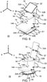
Figur 4A ; - Figuren 5A, 6-9
- schematische Schrägansichten des erfindungsgemäßen Fahrzeugsitzes der zweiten Ausführungsform mit oberer Teilrückenlehne in horizontaler Klappstellung und aufklappbarer Platte in verschiedenen Aufklappstadien;
- Figur 5B
- eine schematische Schrägansicht des erfindungsgemäßen Fahrzeugsitzes gemäß
Figur 5A mit entferntem oberen Rückenpolster; und - Figur 10
- eine schematische Seitenansicht des erfindungsgemäßen Fahrzeugsitzes gemäß einer dritten Ausführungsform mit oberer Teilrückenlehne in horizontaler Klappstellung und Sitzteil in vertikaler Klappstellung.
- Gleiche oder funktional äquivalente Elemente sind in allen Figuren mit denselben Bezugszeichen bezeichnet und sind zum Teil nicht gesondert beschrieben. So bezeichnet beispielsweise das Bezugszeichen 14 in allen Ausführungsformen der
Figuren 1-10 das Sitzteil, dass je nach Ausführungsform und Variante verschieden ausgeführt sein kann. - Die in den Figuren angegebenen Richtungen beziehen sich auf bevorzugte Fahrzeugrichtungen, wenn sich der Fahrzeugsitz 10, 50, 60 im eingebauten Zustand befindet, nämlich die Fahrzeuglängsrichtung (X-Richtung), die Fahrzeugquerrichtung (Y-Richtung) und die Fahrzeughochrichtung (Z-Richtung).
- Die
Figuren 1-2B zeigen den erfindungsgemäßen Fahrzeugsitz 10 gemäß einer ersten Ausführungsform. - Der Fahrzeugsitz 10 umfasst ein Sitzteil 14 und eine Rückenlehne 12.
- Die Rückenlehne 12 zeichnet sich dadurch aus, dass sie zwei Teilrückenlehnen umfasst: eine untere Teilrückenlehne 12B und eine um eine horizontale erste Schwenkachse S2 schwenkbar an der unteren Teilrückenlehne 12B angebrachte obere Teilrückenlehne 12A. Die obere Teilrückenlehne 12A ist aus einer - in den
Figuren 1A und 1B gezeigten - normalen Sitzstellung, in der die obere Teilrückenlehne 12A in etwa vertikal ausgerichtet ist, um die horizontal erste Schwenkachse S2 in Richtung des Sitzteils 14 in eine - in denFiguren 2A und 2B gezeigten - horizontale Klappstellung verschwenkbar. Auf der Rückseite 12C der oberen Teilrückenlehne 12A ist eine Gebrauchsfläche angeordnet, die in der horizontalen Klappstellung als Tisch nutzbar ist. Die horizontale erste Schwenkachse S2 ist vorzugsweise in Y-Richtung ausgerichtet. - In der ersten Ausführungsform ist die Gebrauchsfläche durch eine an der Rückseite 12C der oberen Teilrückenlehne 12A angebrachte Abdeckung 30 gebildet. Vorzugsweise ist die Abdeckung 30 eine Kunststoffabdeckung oder Platte.
- Wie in den
Figuren 1-2B gezeigt, kann die Abdeckung 30 als rechteckige Platte ausgebildet sein, welche die Rückseite 12C teilweise abgedeckt. Alternativ kann die Abdeckung 30 die Rückseite 12C vollständig abdecken. Die Abdeckung 30 kann derart ausgebildet sein, dass sie eine Umfangskontur aufweist, die formkorrespondierend zur Umfangskontur der oberen Teilrückenlehne 12A ausgeführt ist, und/oder eine Erhebung entlang eines Umfangs der Abdeckung 30 zur Ausbildung einer Kante aufweist. - Die obere Teilrückenlehne 12A kann sich in einem oberen Endbereich zur Ausbildung einer Kopfstütze verjüngen. Die Abdeckung 30 kann sich bis in den oberen Endbereich erstreckenden und auch die Kopfstütze abdecken und hierbei die gleiche Umfangskontur wie die Kopfstütze aufweisen (hier nicht dargestellt) und in dem oberen Endbereich optional ferner eine Vertiefung, vorzugsweise zylinderförmige Vertiefung, zur Ausbildung einer Getränkeflaschenhalterung aufweisen.
- Die Abdeckung 30, wie hier beispielhaft dargestellt, umfasst mindestens einen seitlich angeordneten Abdeckungsabschnitt 30A, der mindestens eine Seitenfläche der oberen Teilrückenlehne 12A und ein oberes Beschlagsystem 24, mittels dessen die obere Teilrückenlehne 12A verschwenkbar an der unteren Teilrückenlehne 12B angebracht ist, zumindest teilweise abdeckt. In der gezeigten Ausführungsform ist das obere Beschlagsystem 24 durch den Abdeckungsabschnitt 30A seitlich vollständig abgedeckt.
- Der Fahrzeugsitz 10 kann ferner einen Unterbau 18 umfassen, der vorzugsweise als Konsole oder kastenförmig ausgebildet ist, an dem die untere Teilrückenlehne 12B neigungsverstellbar gehaltert ist. Die untere Teilrückenlehne 12B kann am Unterbau 18 mittels eines unteren Beschlagsystems 26 neigungsverstellbar gehaltert sein. Ferner kann die obere Teilrückenlehne 12A mittels eines oberen Beschlagsystem 24 verschwenkbar an der unteren Teilrückenlehne 12B angebracht sein. Das untere Beschlagsystem 26 und das obere Beschlagsystem 24 können jeweils einen Anschlag aufweisen, der jeweils eine maximale Verschwenkstellung festlegt. Die Anschläge können jeweils so festgelegt sein, dass sich bei maximaler Verschwenkstellung der unteren Teilrückenlehne 12B und der oberen Teilrückenlehne 12A die obere Teilrückenlehne 12A in der horizontalen Klappstellung befindet.
- Wie z. B. in den
Figuren 2A und 2B dargestellt, kann die maximale Verschwenkstellung der unteren Teilrückenlehne 12B einer vertikalen Ausrichtung der unteren Teilrückenlehne 12B entsprechen, d. h. es kann kein Neigungswinkel der unteren Teilrückenlehne 12B im Bereich von 90° in Richtung des Sitzteils 14 eingestellt werden. Ferner kann die maximale Verschwenkstellung der oberen Teilrückenlehne 12A eine relativ zur unteren Teilrückenlehne 12B senkrechten Ausrichtung entsprechen, sodass sich die obere Teilrückenlehne 12A bei maximaler Verschwenkstellung der unteren Teilrückenlehne 12B und der oberen Teilrückenlehne 12A in der horizontalen Klappstellung befindet. - Optional kann der Fahrzeugsitz 10 unterseitig entlang einer Schienenanordnung 20 horizontal verschiebbar angeordnet oder anordbar sein. Die Schienenanordnung 20 kann mindestens eine Bodenschiene 20B und eine gegenüber dieser Bodenschiene 20B in einer Längsverstellrichtung L verschiebbare Sitzschiene 20A umfassen, wobei die Bodenschiene 20B mit der Sitzschiene 20A mittels einer lösbaren Verriegelungseinrichtung lösbar verriegelt werden kann. Die in
Figur 1 angegebene Längsverstellrichtung L entspricht der X-Richtung. - Ferner optional kann der Fahrzeugsitz 10 unterseitig auf einer Dreheinrichtung 40 gelagert sein. Die Dreheinrichtung 40 kann als drehtellerartige Dreheinrichtung 40 ausgeführt sein, mittels derer der Fahrzeugsitz 10 um eine vertikale Drehachse verschwenkbar ist.
- Die
Figuren 3A-9 zeigen den erfindungsgemäßen Fahrzeugsitz 50 gemäß einer zweiten Ausführungsform. Die zweite Ausführungsform unterscheidet sich von der ersten Ausführungsform dadurch, dass die Gebrauchsfläche nicht durch die Abdeckung 30 gebildet ist, sondern durch eine an der Rückseite 12C gehalterte, aufklappbare Platte 32. - Die aufklappbare Platte 32 weist zwei zueinander verschwenkbare Teilplatten 32A, 32B auf, die in einem zusammengeklappten Zustand einen Stapel der Teilplatten 32A, 32B bilden. Der Stapel kann durch ein Gelenk 36 und eine lösbare Verriegelungsvorrichtung 38, die an gegenüberliegenden Seiten des Stapels angeordnet sind, an der oberen Teilrückenlehne 12A fixierbar werden. Die aufklappbare Platte 32 kann auch mehr als zwei zueinander verschwenkbare Teilplatten 32A, 32B aufweisen.
- Eine erste Teilplatte 32B weist einen Überstand auf, der mit dem Gelenk 36 verbunden ist, und im zusammengeklappten Zustand an einer der Rückseite 12C des oberen Rückenlehnenteils 12A abgewandten Seite des Stapels angeordnet ist.
- Die
Figuren 5A und6-9 illustrieren das Aufklappen der aufklappbaren Platte 32. - Zunächst wird die Verriegelungsvorrichtung 38 gelöst und der Stapel der Teilplatten 32A, 32B ausgelenkt, vorzugsweise bis der Überstand der ersten Teilplatte 32A an einer Seitenfläche der oberen Teilrückenlehne 12A anliegt und/oder der Stapel in etwa senkrecht zur Rückseite 12C des oberen Rückenlehnenteils 12A ausgelenkt ist (
Figur 5A ). - Dann wird die zweite Teilplatte 32A, welche nicht mit dem Gelenk 36 verbunden ist, ausgelenkt. Bei der zweiten Teilplatte 32A handelt es sich um die Teilplatte, die im zusammengeklappten Zustand an einer der Rückseite 12C zugewandten Seite des Stapels angeordnet ist, also im zusammengeklappten Zustand an der Rückseite 12C anliegt. Die zweite Teilplatte 32A wird in Richtung der Rückseite 12C ausgeschwenkt und soweit ausgelenkt, bis sie fluchtend zur ersten Teilplatte 32B angeordnet ist, und so die beiden Teilplatten 32A, 32B die Platte 32 ausbilden (
Figuren 6 und 7 ). Die schwenkbare Verbindung 32' zwischen den beiden Teilplatten 32A,32B kann so ausgebildet sein, dass eine Arretierung zwischen den beiden Teilplatten 32A, 32B erfolgt, wenn diese fluchtend zueinander angeordnet sind. - Anschließend wird die Platte 32 mittels des Gelenks 36 wieder in Richtung der Rückseite 12C zurückgelenkt, bis ein an der ausgeklappten Teilpatte 32A rückseitig zur Gebrauchsfläche angeordnetes zweites Halteelement mit einem am oberen Endbereich der Rückseite 12C angeordnetes erstes Halteelement 34 zusammenwirken kann, um die ausgeklappte Teilplatte 32A an der Rückseite 12C der oberen Teilrückenlehne 12A zu fixieren (
Figuren 8 und 9 ). -
Figur 5B zeigt den Fahrzeugsitz 50 der zweiten Ausführungsform, wobei das obere Rückenpolster entfernt ist. Wie zu erkennen ist, können das erstes Halteelement 34 und das Gelenk 36 am oberen Rückenpolsterträger 12A' bzw. als Teil des oberen Rückenpolsterträgers 12A' ausgebildet sein. - Die
Figur 10 zeigt den erfindungsgemäßen Fahrzeugsitz 60 gemäß einer dritten Ausführungsform. Diese dritte Ausführungsform unterscheidet sich von der ersten Ausführungsform dadurch, dass das Sitzteil 14 um eine horizontale zweite Schwenkachse S1 zwischen einer horizontalen Normalstellung und einer nicht-horizontalen, vorzugsweise vertikalen, Klappstellung verschwenkbar ist. Die horizontale zweite Schwenkachse S1 ist vorzugsweise in Y-Richtung und parallel zur horizontalen ersten Schwenkachse S2 ausgerichtet. - Sind - wie in
Figur 10 gezeigt - sowohl die obere Teilrückenlehne 12A als auch das Sitzteil 14 verschwenkt, so kann die obere Teilrückenlehne 12A das Sitzteil 14 überragen und/oder auf dem Sitzteil aufliegen. - Gemäß der dritten Ausführungsform bildet der Unterbau 18 einen zum Sitzteil 14 hin offenen Hohlraum 18A aus. Ferner ist das Sitzteil 14 auf dem Unterbau 18 mittels einer Schwenkverbindung 28 um die horizontale zweite Schwenkachse S1 schwenkbar gehaltert. Wie zu erkennen ist, ist die Schwenkverbindung 28 beabstandet zu einem Endbereich 14B des Sitzteils 14, der der Rückenlehne 12 in der horizontalen Normalstellung zugewandt ist, angeordnet. Entsprechend kann dieser Endbereich 14B beim Verschwenken des Sitzteils 14 von der horizontalen Normalstellung in dessen Klappstellung in den Hohlraum 18A des Unterbaus 18 eintauchen.
- Um dieses Eintauchen des Endbereich 14B in den Hohlraum 18A des Unterbaus 18 zu gewährleisten, kann der Unterbau 18 eine zum Sitzteil 14 hin offene Kastenform aufweisen. Ferner kann eine Breite des Sitzteils 14 in dem Endbereich 14B, der in der horizontalen Normalstellung zwischen der horizontalen zweiten Schwenkachse S1 und der Rückenlehne 12 liegt, kleiner sein als eine Breite des Sitzteils 14 in einem Vorderbereich 14A, wobei vorzugsweise die Breite des Vorderbereichs 14A größer und die Breite des Endbereichs 14B kleiner als eine Breite des Hohlraums 18A des Unterbaus 18 ist. Die jeweiligen Breiten beziehen sich hierbei auf die jeweiligen Maße in Y-Richtung.
- Das Sitzteil 14 kann ferner mittels einer Arretiervorrichtung (nicht gezeigt) lösbar in der Klappstellung arretiert werden. Die Arretiervorrichtung kann z. B. als Klemmvorrichtung ausgeführt sein, aufweisend eine im Unterbau 18 angeordnete Aufnahme oder Klemme zur Aufnahme eines oder einer an der Unterseite 14C des Sitzteils 14 angeordneten Klemmteils oder Aufnahme. Dazu kann die Klemme und/oder Aufnahme im Unterbau 18 so positioniert ist, dass beim Verschwenken des Sitzteils 14 von der horizontalen Normalstellung in dessen Klappstellung der in den Hohlraum 18A eintauchende Endbereich 14B des Sitzteils 14 an der Klemme und/oder Aufnahme arretiert wird, vorzugsweise in dem ein Rohrabschnitt eines Traggestells des Sitzteils 14 an der Klemme und/oder Aufnahme arretiert wird.
- Die Erfindung ist nicht auf die vorstehend beschriebenen bevorzugten Ausführungsformen beschränkt. Vielmehr ist eine Vielzahl von Varianten und Abwandlungen möglich, die ebenfalls von dem Erfindungsgedanken Gebrauch machen und deshalb in den Schutzbereich fallen. Insbesondere beansprucht die Erfindung auch Schutz für den Gegenstand und die Merkmale der Unteransprüche unabhängig von den in Bezug genommenen Ansprüchen. Insbesondere sind die einzelnen Merkmale des unabhängigen Anspruchs 1 jeweils unabhängig voneinander offenbart. Zusätzlich sind auch die Merkmale der Unteransprüche unabhängig von sämtlichen Merkmalen des unabhängigen Anspruchs 1 offenbart.
-
- 10, 50, 60
- Fahrzeugsitz
- 12
- Rückenlehne
- 12A
- Obere Teilrückenlehne
- 12B
- Untere Teilrückenlehne
- 12C
- Rückseite der oberen Teilrückenlehne
- 14
- Sitzteil
- 14A
- Vorderbereich des Sitzteils
- 14B
- Endbereich des Sitzteils
- 16
- Kopfstütze
- 18
- Unterbau
- 20
- Längsverstellvorrichtung
- 20A
- Sitzschiene
- 20B
- Bodenschiene
- 24
- Oberes Beschlagsystem
- 26
- Unteres Beschlagsystem
- 28
- Schwenkverbindung
- 30
- Abdeckung
- 30A
- Abdeckungsabschnitt
- 32
- Platte
- 32A, 32B
- Teilplatte
- 32'
- Schwenkbare Verbindung der Teilplatten
- 34
- Erstes Halteelement
- 36
- Gelenk
- 38
- Verriegelungsvorrichtung
- 40
- Dreheinrichtung
- S1
- Horizontale zweite Schwenkachse
- S2
- Horizontale erste Schwenkachse
- L
- Längsverstellrichtung
Claims (18)
- Fahrzeugsitz (10; 50; 60), vorzugsweise Kraftfahrzeugsitz, umfassend:a) ein Sitzteil (14), undb) eine Rückenlehne (12), umfassend eine untere Teilrückenlehne (12B) und eine um eine horizontale erste Schwenkachse (S2) schwenkbar an der unteren Teilrückenlehne (12B) angebrachte obere Teilrückenlehne (12A), wobei die obere Teilrückenlehne (12A) um die erste Schwenkachse (S2) in Richtung des Sitzteils (14) in eine horizontale Klappstellung verschwenkbar ist und auf deren Rückseite (12C) eine Gebrauchsfläche angeordnet ist, die in der horizontalen Klappstellung als Tisch nutzbar ist.
- Fahrzeugsitz (10) nach Anspruch 1, wobei die Gebrauchsfläche durch eine an der Rückseite (12C) der oberen Teilrückenlehne (12A) angebrachte Abdeckung (30), vorzugsweise eine Kunststoffabdeckung oder Platte, gebildet ist.
- Fahrzeugsitz (10) nach Anspruch 2, wobei die Abdeckung (30)a) die Rückseite (12C) der oberen Teilrückenlehne (12A) vollständig abdeckt; und/oderb) eine Umfangskontur aufweist, die formkorrespondierend zur Umfangskontur der oberen Teilrückenlehne (12A) ausgeführt ist; und/oderc) eine Erhebung entlang eines Umfangs der Abdeckung (30) aufweist zur Ausbildung einer Kante.
- Fahrzeugsitz (10) nach Anspruch 2 oder 3, wobei die obere Teilrückenlehne (12A) sich in einem oberen Endbereich zur Ausbildung einer Kopfstütze (16) verjüngt und die Abdeckung (30) sich bis in den oberen Endbereich erstreckt und in dem oberen Endbereich eine Vertiefung, vorzugsweise zylinderförmige Vertiefung, zur Ausbildung einer Getränkeflaschenhalterung aufweist.
- Fahrzeugsitz (10) nach einem der Ansprüche 2 bis 4, wobei die Abdeckung (30) mindestens einen Abdeckungsabschnitt (30A) umfasst, der mindestens eine Seitenfläche der oberen Teilrückenlehne (12A) und ein oberes Beschlagsystem (24), mittels dessen die obere Teilrückenlehne (12A) verschwenkbar an der unteren Teilrückenlehne (12B) angebracht ist, zumindest teilweise abdeckt.
- Fahrzeugsitz (10) nach einem der vorherigen Ansprüche, wobei die Gebrauchsfläche durch eine an der Rückseite (12C) der oberen Teilrückenlehne (12A) angebrachte Platte (32) gebildet ist.
- Fahrzeugsitz (50) nach Anspruch 1, wobei die Gebrauchsfläche durch eine an der Rückseite (12C) der oberen Teilrückenlehne (12A) gehalterte, aufklappbare Platte (32) gebildet ist.
- Fahrzeugsitz (50) nach Anspruch 7, wobei die aufklappbare Platte (32) mindestens zwei zueinander verschwenkbare Teilplatten (32A, 32B) aufweist, die einem zusammengeklappten Zustand einen Stapel der Teilplatten (32A, 32B) bilden, der durch ein Gelenk (36) und eine lösbare Verriegelungsvorrichtung (38), die an gegenüberliegenden Seiten des Stapels angeordnet sind, an der oberen Teilrückenlehne (12A) fixierbar ist.
- Fahrzeugsitz (50) nach Anspruch 8, wobei eine erste Teilplatte (32B) der Teilplatten (32A, 32B)a) einen Überstand aufweist, der mit dem Gelenk (36) verbunden ist, undb) im zusammengeklappten Zustand an einer der Rückseite (12C) des oberen Rückenlehnenteils (12A) abgewandten Seite des Stapels angeordnet ist.
- Fahrzeugsitz (50) nach Anspruch 8 oder 9, wobei am oberen Endbereich der Rückseite (12C) der oberen Teilrückenlehne (12A) ein erstes Halteelement (34) angeordnet ist, das ausgebildet ist, mit einem an einer ausgeklappten Teilpatte (32A) rückseitig zur Gebrauchsfläche angeordneten zweiten Halteelement zusammenzuwirken, um die ausgeklappte Teilplatte (32A) an der Rückseite (12C) der oberen Teilrückenlehne (12A) zu fixieren.
- Fahrzeugsitz (10; 50; 60) nach einem der vorherigen Ansprüche, ferner umfassend einen Unterbau (18), der vorzugsweise als Konsole oder kastenförmig ausgebildet ist, an dem die untere Teilrückenlehne (12B) neigungsverstellbar gehaltert ist,a) wobei die untere Teilrückenlehne (12B) am Unterbau (18) mittels eines unteren Beschlagsystems (26) neigungsverstellbar gehaltert ist; undb) wobei die obere Teilrückenlehne (12A) mittels eines oberen Beschlagsystem (24) verschwenkbar an der unteren Teilrückenlehne (12B) angebracht ist.
- Fahrzeugsitz (10; 50; 60) nach Anspruch 11, wobei das untere und das obere Beschlagsystem (24, 26) jeweils einen Anschlag aufweisen, der jeweils eine maximale Verschwenkstellung festlegt, wobei die Anschläge vorzugsweise jeweils so festgelegt sind, dass sich bei maximaler Verschwenkstellung der unteren Teilrückenlehne (12B) und der oberen Teilrückenlehne (12A) die obere Teilrückenlehne (12A) in der horizontalen Klappstellung befindet.
- Fahrzeugsitz (10; 50; 60) nach Anspruch 11 oder 12, wobei die untere Teilrückenlehne (12B) und/oder obere Teilrückenlehne (12A)a) stufenlos, oderb) gerastert, beispielsweise mittels eines Reclainers, oderc) elektro-motorisch verschwenkbar ausgeführt sind.
- Fahrzeugsitz (60) nach einem der vorherigen Ansprüche, wobei das Sitzteil (14) um eine horizontale zweite Schwenkachse (S1) zwischen einer horizontalen Normalstellung und einer nicht-horizontalen, vorzugsweise vertikalen, Klappstellung verschwenkbar ist; und wobei, wenn sich die obere Teilrückenlehne (12A) in der horizontalen Klappstellung und das Sitzteil (14) in dessen Klappstellung befinden, die obere Teilrückenlehne (12A) das Sitzteil (14) überragt und/oder auf dem Sitzteil (14) aufliegt.
- Fahrzeugsitz (60) nach Anspruch 14, umfassend den Unterbau (18) gemäß Anspruch 11, wobeia) das Sitzteil (14) auf dem Unterbau (18) mittels einer Schwenkverbindung (28) um die horizontale zweite Schwenkachse (S1) schwenkbar gehaltert ist,b) der Unterbau (18) einen zum Sitzteil (14) hin offenen Hohlraum ausbildet, undc) die Schwenkverbindung (28) beabstandet zu einem Endbereich (14B) des Sitzteils (14), der der unteren Teilrückenlehne (12B) in der horizontalen Normalstellung zugewandt ist, angeordnet ist, so dass beim Verschwenken des Sitzteils (14) von der horizontalen Normalstellung in dessen Klappstellung dieser Endbereich (14B) in den Hohlraum des Unterbaus (18) eintaucht.
- Fahrzeugsitz (10; 50; 60) nach einem der vorhergehenden Ansprüche, wobei der Fahrzeugsitz (10) unterseitiga) entlang einer Schienenanordnung (20) horizontal verschiebbar angeordnet oder anordbar ist; und/oderb) auf einer Dreheinrichtung (40), vorzugsweise einer drehtellerartigen Dreheinrichtung, gelagert ist, mittels derer der Fahrzeugsitz um eine vertikale Drehachse verschwenkbar ist.
- Fahrzeugsitz (10; 50; 60) nach einem der vorhergehenden Ansprüche, wobei der Fahrzeugsitz ein Beifahrersitz für ein Fahrerhaus eines Nutzfahrzeugs ist.
- Fahrzeug, vorzugsweise Nutzfahrzeug, mit einem Fahrzeugsitz (10; 50; 60) gemäß einem der vorhergehenden Ansprüche.
Applications Claiming Priority (1)
| Application Number | Priority Date | Filing Date | Title |
|---|---|---|---|
| DE102020120852.9A DE102020120852A1 (de) | 2020-08-07 | 2020-08-07 | Fahrzeugsitz |
Publications (3)
| Publication Number | Publication Date |
|---|---|
| EP3950418A1 true EP3950418A1 (de) | 2022-02-09 |
| EP3950418B1 EP3950418B1 (de) | 2025-06-25 |
| EP3950418C0 EP3950418C0 (de) | 2025-06-25 |
Family
ID=76971745
Family Applications (1)
| Application Number | Title | Priority Date | Filing Date |
|---|---|---|---|
| EP21186418.6A Active EP3950418B1 (de) | 2020-08-07 | 2021-07-19 | Fahrzeugsitz |
Country Status (2)
| Country | Link |
|---|---|
| EP (1) | EP3950418B1 (de) |
| DE (1) | DE102020120852A1 (de) |
Citations (7)
| Publication number | Priority date | Publication date | Assignee | Title |
|---|---|---|---|---|
| KR970036660A (ko) * | 1995-12-28 | 1997-07-22 | 김태구 | 자동차의 2 중 홀딩 시트 |
| GB2395118A (en) * | 2002-11-09 | 2004-05-19 | Ford Global Tech Llc | Seat assembly having a table extending from upper backrest |
| US20050248200A1 (en) * | 2004-05-10 | 2005-11-10 | Bernard Pradier | Vehicle seat |
| EP1932713B1 (de) * | 2006-12-12 | 2011-07-27 | GM Global Technology Operations LLC | Mittelsitz für eine Kraftfahrzeugrücksitzbank |
| CN202439580U (zh) * | 2012-02-29 | 2012-09-19 | 许洋 | 公交车座椅 |
| DE112011105252T5 (de) * | 2011-05-18 | 2014-02-13 | Volvo Lastvagnar Ab | Fahrerkabine für einen Schwerlastkraftwagen |
| FR3008935A1 (fr) * | 2013-07-23 | 2015-01-30 | Peugeot Citroen Automobiles Sa | Tablette d'ecriture pour siege de vehicule avec espace de rangement |
Family Cites Families (11)
| Publication number | Priority date | Publication date | Assignee | Title |
|---|---|---|---|---|
| US557406A (en) | 1896-03-31 | linn x | ||
| US2963078A (en) * | 1959-11-19 | 1960-12-06 | Charles H Ferrelle | Folding table for motor vehicles |
| JP2971404B2 (ja) | 1996-09-27 | 1999-11-08 | 本田技研工業株式会社 | 車両のシート構造 |
| DE19956404C1 (de) | 1999-11-24 | 2001-02-08 | Faure Bertrand Sitztech Gmbh | Kraftfahrzeugsitz mit vorklappbarer Rückenlehne |
| DE10057450A1 (de) | 2000-11-20 | 2002-05-23 | Lear Corp Gmbh & Co Kg | Sitzelement und Ablage- und Aufbewahrungssystem |
| FR2817811B1 (fr) | 2000-12-12 | 2004-11-26 | Faurecia Sieges Automobile | Siege de vehicule transformable |
| DE20100008U1 (de) | 2001-01-03 | 2002-05-08 | Johnson Controls GmbH, 51399 Burscheid | Schwenkbare Armauflage |
| DE10257171B4 (de) | 2002-12-03 | 2014-09-11 | Volkswagen Ag | Variable Hintersitzlehne mit Multifunktionsklappe |
| DE102014013955B4 (de) | 2014-09-19 | 2024-03-07 | Isringhausen Gmbh & Co. Kg | Fahrzeugsitz, insbesondere für ein Nutzfahrzeug oder ein Campingmobil |
| KR20160062238A (ko) * | 2014-11-24 | 2016-06-02 | 대원강업주식회사 | 차량용 컵홀더 일체형 헤드레스트 |
| TR201912174A2 (tr) * | 2019-08-09 | 2021-02-22 | Assan Hanil Otomotiv Sanayi Ve Ticaret Anonim Sirketi | Paralel sevi̇yede kalan katlanan koltuk arkaliği |
-
2020
- 2020-08-07 DE DE102020120852.9A patent/DE102020120852A1/de active Pending
-
2021
- 2021-07-19 EP EP21186418.6A patent/EP3950418B1/de active Active
Patent Citations (7)
| Publication number | Priority date | Publication date | Assignee | Title |
|---|---|---|---|---|
| KR970036660A (ko) * | 1995-12-28 | 1997-07-22 | 김태구 | 자동차의 2 중 홀딩 시트 |
| GB2395118A (en) * | 2002-11-09 | 2004-05-19 | Ford Global Tech Llc | Seat assembly having a table extending from upper backrest |
| US20050248200A1 (en) * | 2004-05-10 | 2005-11-10 | Bernard Pradier | Vehicle seat |
| EP1932713B1 (de) * | 2006-12-12 | 2011-07-27 | GM Global Technology Operations LLC | Mittelsitz für eine Kraftfahrzeugrücksitzbank |
| DE112011105252T5 (de) * | 2011-05-18 | 2014-02-13 | Volvo Lastvagnar Ab | Fahrerkabine für einen Schwerlastkraftwagen |
| CN202439580U (zh) * | 2012-02-29 | 2012-09-19 | 许洋 | 公交车座椅 |
| FR3008935A1 (fr) * | 2013-07-23 | 2015-01-30 | Peugeot Citroen Automobiles Sa | Tablette d'ecriture pour siege de vehicule avec espace de rangement |
Also Published As
| Publication number | Publication date |
|---|---|
| EP3950418B1 (de) | 2025-06-25 |
| EP3950418C0 (de) | 2025-06-25 |
| DE102020120852A1 (de) | 2022-02-10 |
Similar Documents
| Publication | Publication Date | Title |
|---|---|---|
| DE19605907B4 (de) | Sicherungsvorrichtung für einen Innenraum eines Kraftfahrzeugs | |
| DE19921453C1 (de) | Rücksitzanordnung für Fahrzeuge | |
| EP0211248B1 (de) | Sitzverstellung in einem Kraftwagen | |
| EP0001230B1 (de) | Fahrerhaus für Lastkraftwagen mit Wohnwageneinbauten | |
| DE102006044196A1 (de) | Fahrzeugsitz, der gekippt und in eine Stauvertiefung geklappt werden kann | |
| DE102022113889A1 (de) | Fahrzeug mit umwandelbarem rücksitz | |
| DE202020104560U1 (de) | Fahrzeugsitz | |
| DE69919258T2 (de) | Anordnung von verstaubaren Tischplatten für Kraftfahrzeugsitze | |
| DE19954930C1 (de) | Kraftfahrzeugsitzbank | |
| DE10243836A1 (de) | Fahrzeugelemente-Ablagefächer/Staufächer in einem Backpanel einer Kopfstütze und einer Rückenlehne eines Fahrzeugsitzes | |
| DE102008047659B4 (de) | Schienenfahrzeug | |
| EP2910412B1 (de) | Sitz, insbesondere Fahrgastsitz | |
| DE102007052529B4 (de) | Ein Sitz und Sitzanordnung in einem Kraftfahrzeug | |
| DE202023104382U1 (de) | Fahrzeugsitzbaugruppe mit einer Schwenkneigung | |
| DE20016393U1 (de) | Klapptisch für Land-, Wasser- und Luftfahrzeuge | |
| EP3950419B1 (de) | Fahrzeugsitz | |
| DE202020104559U1 (de) | Fahrzeugsitz | |
| DE102015201054A1 (de) | Ladebodenanordnung in einem Kraftfahrzeug sowie Kraftfahrzeug mit einer derartigen Ladebodenanordnung | |
| EP3950418A1 (de) | Fahrzeugsitz | |
| DE102023118651A1 (de) | Fahrzeug, aufweisend eine ausklappbare arbeitsstation | |
| DE19942892A1 (de) | Ausfahrbares Ablagetableau, insbesondere Klemmbrett in einem Fahrzeuginnenraum | |
| DE102012018351A1 (de) | Fahrzeugsitz sowie Verfahren zum Verbringen eines Fahrzeugsitzes | |
| DE3529735A1 (de) | Lagerung einer kraftfahrzeug-hintersitzlehne | |
| EP1919733B1 (de) | Fahrzeugsitz | |
| DE102024113198A1 (de) | Fahrzeug, das eine durch eine Anhängerkupplung gestützte Heckklappensitzbaugruppe aufweist |
Legal Events
| Date | Code | Title | Description |
|---|---|---|---|
| PUAI | Public reference made under article 153(3) epc to a published international application that has entered the european phase |
Free format text: ORIGINAL CODE: 0009012 |
|
| STAA | Information on the status of an ep patent application or granted ep patent |
Free format text: STATUS: THE APPLICATION HAS BEEN PUBLISHED |
|
| AK | Designated contracting states |
Kind code of ref document: A1 Designated state(s): AL AT BE BG CH CY CZ DE DK EE ES FI FR GB GR HR HU IE IS IT LI LT LU LV MC MK MT NL NO PL PT RO RS SE SI SK SM TR |
|
| STAA | Information on the status of an ep patent application or granted ep patent |
Free format text: STATUS: REQUEST FOR EXAMINATION WAS MADE |
|
| 17P | Request for examination filed |
Effective date: 20220718 |
|
| RBV | Designated contracting states (corrected) |
Designated state(s): AL AT BE BG CH CY CZ DE DK EE ES FI FR GB GR HR HU IE IS IT LI LT LU LV MC MK MT NL NO PL PT RO RS SE SI SK SM TR |
|
| STAA | Information on the status of an ep patent application or granted ep patent |
Free format text: STATUS: EXAMINATION IS IN PROGRESS |
|
| 17Q | First examination report despatched |
Effective date: 20230803 |
|
| GRAP | Despatch of communication of intention to grant a patent |
Free format text: ORIGINAL CODE: EPIDOSNIGR1 |
|
| STAA | Information on the status of an ep patent application or granted ep patent |
Free format text: STATUS: GRANT OF PATENT IS INTENDED |
|
| INTG | Intention to grant announced |
Effective date: 20250122 |
|
| GRAS | Grant fee paid |
Free format text: ORIGINAL CODE: EPIDOSNIGR3 |
|
| GRAA | (expected) grant |
Free format text: ORIGINAL CODE: 0009210 |
|
| STAA | Information on the status of an ep patent application or granted ep patent |
Free format text: STATUS: THE PATENT HAS BEEN GRANTED |
|
| AK | Designated contracting states |
Kind code of ref document: B1 Designated state(s): AL AT BE BG CH CY CZ DE DK EE ES FI FR GB GR HR HU IE IS IT LI LT LU LV MC MK MT NL NO PL PT RO RS SE SI SK SM TR |
|
| REG | Reference to a national code |
Ref country code: GB Ref legal event code: FG4D Free format text: NOT ENGLISH |
|
| REG | Reference to a national code |
Ref country code: CH Ref legal event code: EP |
|
| REG | Reference to a national code |
Ref country code: DE Ref legal event code: R096 Ref document number: 502021007820 Country of ref document: DE |
|
| REG | Reference to a national code |
Ref country code: CH Ref legal event code: EP |
|
| REG | Reference to a national code |
Ref country code: IE Ref legal event code: FG4D Free format text: LANGUAGE OF EP DOCUMENT: GERMAN |
|
| U01 | Request for unitary effect filed |
Effective date: 20250714 |
|
| U07 | Unitary effect registered |
Designated state(s): AT BE BG DE DK EE FI FR IT LT LU LV MT NL PT RO SE SI Effective date: 20250718 |
|
| U20 | Renewal fee for the european patent with unitary effect paid |
Year of fee payment: 5 Effective date: 20250825 |
|
| PG25 | Lapsed in a contracting state [announced via postgrant information from national office to epo] |
Ref country code: NO Free format text: LAPSE BECAUSE OF FAILURE TO SUBMIT A TRANSLATION OF THE DESCRIPTION OR TO PAY THE FEE WITHIN THE PRESCRIBED TIME-LIMIT Effective date: 20250925 Ref country code: GR Free format text: LAPSE BECAUSE OF FAILURE TO SUBMIT A TRANSLATION OF THE DESCRIPTION OR TO PAY THE FEE WITHIN THE PRESCRIBED TIME-LIMIT Effective date: 20250926 |
|
| PG25 | Lapsed in a contracting state [announced via postgrant information from national office to epo] |
Ref country code: HR Free format text: LAPSE BECAUSE OF FAILURE TO SUBMIT A TRANSLATION OF THE DESCRIPTION OR TO PAY THE FEE WITHIN THE PRESCRIBED TIME-LIMIT Effective date: 20250625 |
|
| PG25 | Lapsed in a contracting state [announced via postgrant information from national office to epo] |
Ref country code: RS Free format text: LAPSE BECAUSE OF FAILURE TO SUBMIT A TRANSLATION OF THE DESCRIPTION OR TO PAY THE FEE WITHIN THE PRESCRIBED TIME-LIMIT Effective date: 20250925 |
|
| PG25 | Lapsed in a contracting state [announced via postgrant information from national office to epo] |
Ref country code: IS Free format text: LAPSE BECAUSE OF FAILURE TO SUBMIT A TRANSLATION OF THE DESCRIPTION OR TO PAY THE FEE WITHIN THE PRESCRIBED TIME-LIMIT Effective date: 20251025 |
|
| PG25 | Lapsed in a contracting state [announced via postgrant information from national office to epo] |
Ref country code: SM Free format text: LAPSE BECAUSE OF FAILURE TO SUBMIT A TRANSLATION OF THE DESCRIPTION OR TO PAY THE FEE WITHIN THE PRESCRIBED TIME-LIMIT Effective date: 20250625 |
|
| PG25 | Lapsed in a contracting state [announced via postgrant information from national office to epo] |
Ref country code: CZ Free format text: LAPSE BECAUSE OF FAILURE TO SUBMIT A TRANSLATION OF THE DESCRIPTION OR TO PAY THE FEE WITHIN THE PRESCRIBED TIME-LIMIT Effective date: 20250625 |
|
| PG25 | Lapsed in a contracting state [announced via postgrant information from national office to epo] |
Ref country code: PL Free format text: LAPSE BECAUSE OF FAILURE TO SUBMIT A TRANSLATION OF THE DESCRIPTION OR TO PAY THE FEE WITHIN THE PRESCRIBED TIME-LIMIT Effective date: 20250625 |
|
| PG25 | Lapsed in a contracting state [announced via postgrant information from national office to epo] |
Ref country code: SK Free format text: LAPSE BECAUSE OF FAILURE TO SUBMIT A TRANSLATION OF THE DESCRIPTION OR TO PAY THE FEE WITHIN THE PRESCRIBED TIME-LIMIT Effective date: 20250625 |
|
| PG25 | Lapsed in a contracting state [announced via postgrant information from national office to epo] |
Ref country code: ES Free format text: LAPSE BECAUSE OF FAILURE TO SUBMIT A TRANSLATION OF THE DESCRIPTION OR TO PAY THE FEE WITHIN THE PRESCRIBED TIME-LIMIT Effective date: 20250625 |
|
| REG | Reference to a national code |
Ref country code: CH Ref legal event code: H13 Free format text: ST27 STATUS EVENT CODE: U-0-0-H10-H13 (AS PROVIDED BY THE NATIONAL OFFICE) Effective date: 20260224 |
|
| PG25 | Lapsed in a contracting state [announced via postgrant information from national office to epo] |
Ref country code: MC Free format text: LAPSE BECAUSE OF FAILURE TO SUBMIT A TRANSLATION OF THE DESCRIPTION OR TO PAY THE FEE WITHIN THE PRESCRIBED TIME-LIMIT Effective date: 20250625 |
|
| PG25 | Lapsed in a contracting state [announced via postgrant information from national office to epo] |
Ref country code: CH Free format text: LAPSE BECAUSE OF NON-PAYMENT OF DUE FEES Effective date: 20250731 |
|
| PLBE | No opposition filed within time limit |
Free format text: ORIGINAL CODE: 0009261 |
|
| STAA | Information on the status of an ep patent application or granted ep patent |
Free format text: STATUS: NO OPPOSITION FILED WITHIN TIME LIMIT |