EP3947104B1 - Wagen zum tragen und wiegen eines containers - Google Patents
Wagen zum tragen und wiegen eines containers Download PDFInfo
- Publication number
- EP3947104B1 EP3947104B1 EP20713935.3A EP20713935A EP3947104B1 EP 3947104 B1 EP3947104 B1 EP 3947104B1 EP 20713935 A EP20713935 A EP 20713935A EP 3947104 B1 EP3947104 B1 EP 3947104B1
- Authority
- EP
- European Patent Office
- Prior art keywords
- trolley
- container
- carriage
- suspension structure
- suspension
- Prior art date
- Legal status (The legal status is an assumption and is not a legal conclusion. Google has not performed a legal analysis and makes no representation as to the accuracy of the status listed.)
- Active
Links
- 238000005303 weighing Methods 0.000 title description 6
- 239000000725 suspension Substances 0.000 claims description 346
- 238000003860 storage Methods 0.000 claims description 33
- 238000005259 measurement Methods 0.000 claims description 19
- 230000007423 decrease Effects 0.000 claims description 11
- 238000005096 rolling process Methods 0.000 claims description 11
- 230000006835 compression Effects 0.000 description 13
- 238000007906 compression Methods 0.000 description 13
- 230000005484 gravity Effects 0.000 description 13
- 230000000694 effects Effects 0.000 description 8
- 230000003287 optical effect Effects 0.000 description 8
- 230000008901 benefit Effects 0.000 description 7
- 239000004744 fabric Substances 0.000 description 6
- 238000013519 translation Methods 0.000 description 6
- 230000007704 transition Effects 0.000 description 4
- 238000010200 validation analysis Methods 0.000 description 3
- 238000012550 audit Methods 0.000 description 2
- 238000009826 distribution Methods 0.000 description 2
- 229920001971 elastomer Polymers 0.000 description 2
- 230000010354 integration Effects 0.000 description 2
- 238000002955 isolation Methods 0.000 description 2
- 238000000034 method Methods 0.000 description 2
- 210000000056 organ Anatomy 0.000 description 2
- 241001272720 Medialuna californiensis Species 0.000 description 1
- 241000287107 Passer Species 0.000 description 1
- 241001080024 Telles Species 0.000 description 1
- 230000009471 action Effects 0.000 description 1
- 230000003466 anti-cipated effect Effects 0.000 description 1
- 238000013459 approach Methods 0.000 description 1
- 230000008859 change Effects 0.000 description 1
- 238000013461 design Methods 0.000 description 1
- 238000001514 detection method Methods 0.000 description 1
- 238000010586 diagram Methods 0.000 description 1
- 239000000806 elastomer Substances 0.000 description 1
- 238000003780 insertion Methods 0.000 description 1
- 230000037431 insertion Effects 0.000 description 1
- 230000002452 interceptive effect Effects 0.000 description 1
- 230000007257 malfunction Effects 0.000 description 1
- 239000002184 metal Substances 0.000 description 1
- 238000003825 pressing Methods 0.000 description 1
- 238000012552 review Methods 0.000 description 1
- 239000005060 rubber Substances 0.000 description 1
- 239000007787 solid Substances 0.000 description 1
- 238000007619 statistical method Methods 0.000 description 1
- 230000002123 temporal effect Effects 0.000 description 1
- 210000001519 tissue Anatomy 0.000 description 1
- 238000012795 verification Methods 0.000 description 1
Images


Classifications
-
- B—PERFORMING OPERATIONS; TRANSPORTING
- B62—LAND VEHICLES FOR TRAVELLING OTHERWISE THAN ON RAILS
- B62B—HAND-PROPELLED VEHICLES, e.g. HAND CARTS OR PERAMBULATORS; SLEDGES
- B62B3/00—Hand carts having more than one axis carrying transport wheels; Steering devices therefor; Equipment therefor
- B62B3/10—Hand carts having more than one axis carrying transport wheels; Steering devices therefor; Equipment therefor characterised by supports specially adapted to objects of definite shape
- B62B3/106—Hand carts having more than one axis carrying transport wheels; Steering devices therefor; Equipment therefor characterised by supports specially adapted to objects of definite shape the objects being bags
-
- G—PHYSICS
- G01—MEASURING; TESTING
- G01G—WEIGHING
- G01G19/00—Weighing apparatus or methods adapted for special purposes not provided for in the preceding groups
- G01G19/08—Weighing apparatus or methods adapted for special purposes not provided for in the preceding groups for incorporation in vehicles
-
- B—PERFORMING OPERATIONS; TRANSPORTING
- B62—LAND VEHICLES FOR TRAVELLING OTHERWISE THAN ON RAILS
- B62B—HAND-PROPELLED VEHICLES, e.g. HAND CARTS OR PERAMBULATORS; SLEDGES
- B62B3/00—Hand carts having more than one axis carrying transport wheels; Steering devices therefor; Equipment therefor
- B62B3/14—Hand carts having more than one axis carrying transport wheels; Steering devices therefor; Equipment therefor characterised by provisions for nesting or stacking, e.g. shopping trolleys
- B62B3/1404—Means for facilitating stowing or transporting of the trolleys; Antitheft arrangements
-
- B—PERFORMING OPERATIONS; TRANSPORTING
- B62—LAND VEHICLES FOR TRAVELLING OTHERWISE THAN ON RAILS
- B62B—HAND-PROPELLED VEHICLES, e.g. HAND CARTS OR PERAMBULATORS; SLEDGES
- B62B3/00—Hand carts having more than one axis carrying transport wheels; Steering devices therefor; Equipment therefor
- B62B3/14—Hand carts having more than one axis carrying transport wheels; Steering devices therefor; Equipment therefor characterised by provisions for nesting or stacking, e.g. shopping trolleys
- B62B3/1492—Wheel arrangements
-
- B—PERFORMING OPERATIONS; TRANSPORTING
- B62—LAND VEHICLES FOR TRAVELLING OTHERWISE THAN ON RAILS
- B62B—HAND-PROPELLED VEHICLES, e.g. HAND CARTS OR PERAMBULATORS; SLEDGES
- B62B3/00—Hand carts having more than one axis carrying transport wheels; Steering devices therefor; Equipment therefor
- B62B3/14—Hand carts having more than one axis carrying transport wheels; Steering devices therefor; Equipment therefor characterised by provisions for nesting or stacking, e.g. shopping trolleys
- B62B3/18—Hand carts having more than one axis carrying transport wheels; Steering devices therefor; Equipment therefor characterised by provisions for nesting or stacking, e.g. shopping trolleys nestable by means of pivoted supports or support parts, e.g. baskets
- B62B3/182—Swinging baskets
-
- B—PERFORMING OPERATIONS; TRANSPORTING
- B62—LAND VEHICLES FOR TRAVELLING OTHERWISE THAN ON RAILS
- B62B—HAND-PROPELLED VEHICLES, e.g. HAND CARTS OR PERAMBULATORS; SLEDGES
- B62B3/00—Hand carts having more than one axis carrying transport wheels; Steering devices therefor; Equipment therefor
- B62B3/14—Hand carts having more than one axis carrying transport wheels; Steering devices therefor; Equipment therefor characterised by provisions for nesting or stacking, e.g. shopping trolleys
- B62B3/18—Hand carts having more than one axis carrying transport wheels; Steering devices therefor; Equipment therefor characterised by provisions for nesting or stacking, e.g. shopping trolleys nestable by means of pivoted supports or support parts, e.g. baskets
- B62B3/184—Nestable roll containers
-
- B—PERFORMING OPERATIONS; TRANSPORTING
- B62—LAND VEHICLES FOR TRAVELLING OTHERWISE THAN ON RAILS
- B62B—HAND-PROPELLED VEHICLES, e.g. HAND CARTS OR PERAMBULATORS; SLEDGES
- B62B5/00—Accessories or details specially adapted for hand carts
-
- B—PERFORMING OPERATIONS; TRANSPORTING
- B62—LAND VEHICLES FOR TRAVELLING OTHERWISE THAN ON RAILS
- B62B—HAND-PROPELLED VEHICLES, e.g. HAND CARTS OR PERAMBULATORS; SLEDGES
- B62B5/00—Accessories or details specially adapted for hand carts
- B62B5/06—Hand moving equipment, e.g. handle bars
-
- G—PHYSICS
- G01—MEASURING; TESTING
- G01G—WEIGHING
- G01G3/00—Weighing apparatus characterised by the use of elastically-deformable members, e.g. spring balances
- G01G3/12—Weighing apparatus characterised by the use of elastically-deformable members, e.g. spring balances wherein the weighing element is in the form of a solid body stressed by pressure or tension during weighing
- G01G3/14—Weighing apparatus characterised by the use of elastically-deformable members, e.g. spring balances wherein the weighing element is in the form of a solid body stressed by pressure or tension during weighing measuring variations of electrical resistance
-
- B—PERFORMING OPERATIONS; TRANSPORTING
- B62—LAND VEHICLES FOR TRAVELLING OTHERWISE THAN ON RAILS
- B62B—HAND-PROPELLED VEHICLES, e.g. HAND CARTS OR PERAMBULATORS; SLEDGES
- B62B2202/00—Indexing codes relating to type or characteristics of transported articles
- B62B2202/26—Handbags, e.g. shopping bags
-
- B—PERFORMING OPERATIONS; TRANSPORTING
- B62—LAND VEHICLES FOR TRAVELLING OTHERWISE THAN ON RAILS
- B62B—HAND-PROPELLED VEHICLES, e.g. HAND CARTS OR PERAMBULATORS; SLEDGES
- B62B2203/00—Grasping, holding, supporting the objects
- B62B2203/02—Grasping, holding, supporting the objects suspended
-
- B—PERFORMING OPERATIONS; TRANSPORTING
- B62—LAND VEHICLES FOR TRAVELLING OTHERWISE THAN ON RAILS
- B62B—HAND-PROPELLED VEHICLES, e.g. HAND CARTS OR PERAMBULATORS; SLEDGES
- B62B2203/00—Grasping, holding, supporting the objects
- B62B2203/50—Grasping, holding, supporting the objects comprising weighing means
Definitions
- the invention relates to the field of transport trolleys. It is particularly applicable for distribution areas such as supermarkets. It concerns more precisely the integration of measuring devices within trolleys in order to weigh the articles selected by the user and placed in the trolley.
- supermarkets provide self-checkout devices called automatic cash registers allowing people doing their shopping, once all of their shopping has been placed in the cart, to calculate the amount to be paid and make payment. of this sum.
- This includes a step of scanning each article, using an optical reader, then a step of weighing each selected article. This weighing step makes it possible in particular to ensure that each item placed by the user in the cart has been scanned and therefore has been counted for payment.
- the document FROM 20 2018 000 613 U1 describes a transport trolley having a loading platform equipped with a weight sensor and which can slide on a loading platform of another trolley to allow the nesting of two trolleys.
- the present invention aims to satisfy this need.
- the cart comprises at least one container in which at least one product is intended to be placed.
- the cart includes a suspension structure supported by the supporting structure and configured to suspend at least one container in which at least one product is intended to be placed.
- the cart is configured so that the at least one container is entirely suspended from the suspension structure, for example by reception areas.
- the cart comprises at least one measuring device carried in part at least by the suspension structure and being intended to measure at least one parameter relating to the weight of the at least one container when the container is suspended from the suspension structure.
- the suspension structure advantageously a frame, the at least one container and the chassis of said cart are shaped to cooperate with a suspension structure, advantageously a frame, at least one container and a chassis. another carriage so as to allow at least partial nesting of at least part of said other carriage in at least part of said carriage by cooperation of the suspension structure, advantageously of the frame, of the at least one container and of the chassis of said other trolley with the suspension structure, advantageously the frame, the at least one container and the chassis of said trolley.
- the suspension structure advantageously the frame, the at least one container and the chassis of said cart are shaped to cooperate with the suspension structure, advantageously the frame, the at least one container and the chassis of another cart so as to allow at least partial nesting of at least part of said cart in at least part of said other cart by cooperation of the suspension structure, advantageously of the frame, of the at least one container and the chassis of said trolley with the suspension structure, advantageously the frame, the at least one container and the chassis of said other trolley.
- both part of a first carriage enters a second carriage and both another part of the second carriage enters the first carriage.
- the suspension structure of said cart is shaped to cooperate with the suspension structure of another cart so as to allow at least partial nesting of said cart in said other cart by cooperation of the suspension structure of said cart with the suspension structure of said other cart.
- the suspension structure of said trolley is shaped to cooperate with the suspension structure of another trolley so as to allow at least partial nesting of the supporting structure of said trolley in a supporting structure of of said other cart.
- the present invention offers the user a cart making it possible to weigh the at least one container and the at least one product that he wishes to purchase while allowing him to store the cart easily and in a space-saving manner. These two functions are made possible in particular through the presence of the suspension structure.
- the present invention allows supermarkets to combat existing fraud using known self-checkout systems and to obtain a considerable saving of space for storing the trolley when it is not in use. .
- the present invention makes it possible to integrate very few mechanical, mobile or moving parts. This makes it possible to increase the robustness and reliability of the present invention.
- trolleys are regularly abused by users, so it is of great advantage to have robust trolleys.
- the present invention in addition to the multiple innovations in design and use that it brings, makes it possible to have a robust trolley.
- the present invention also has optimized physical characteristics (size, container, etc.). These characteristics also make it possible to integrate containers in the form of bags or not.
- the invention relates to an assembly comprising a cart according to the invention and at least one container, preferably a plurality of containers, each container configured to cooperate with the suspension structure so that the container is entirely suspended by the suspension structure.
- the term “identical” used such as for example “a first element identical to a second element” means that these two elements have structurally and/or functionally similar characteristics.
- bins, containers, boxes or receptacles are considered equivalent and can be substituted for one another.
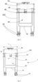
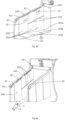
- the present invention relates to a trolley 1, for example for a supermarket as described below.
- Trolley 1 is a transport trolley, thus allowing loads to be transported. As a non-limiting example, these loads are shopping items placed in a container.
- Trolley 1 could also be used in all industrial areas requiring the transport of loads, such as the food industry or in airports for the transport of luggage.
- THE figures 1 to 11 represent the cart 1, which comprises at least one device 50 for measuring a parameter relating to the weight of the at least one container and the at least one product.
- the at least one product is generally placed in the at least one container by the user.
- the container can be a suspended bin 40 as shown in the figures 1 to 9
- the container can also be a bag 90 of the plastic bag type, shopping bag or rigid bag as shown in figures 8 And 9
- the at least one container (40, 90) can be any element having the function of containing the at least one product.
- the measuring device 50 may comprise at least one force sensor 51, which may also be designated a force sensor, represented by the Figure 11
- the measuring device is configured to measure a parameter relating to the weight of the at least one container (40, 90) and the at least one product it contains.
- the measuring device 50 can be configured to form a cantilever type weight sensor.
- the force sensor 51 includes a strain gauge or strain gauge.
- the force sensor 51 can be a so-called “single point” sensor, in the shape of an S. This makes it possible to measure a parameter relating to the weight of the at least one container (40, 90) and the at least one product that 'it contains.
- the measuring device 50 mainly measures a parameter relating to the weight of the at least one product.
- the present invention proposes a cart 1 capable of subtracting the weight of the at least one container (40, 90) from the total weight measured in order to obtain only the measurement of the weight of at least one product.
- the carriage 1 comprises at least one chassis 10.
- chassis is meant a rigid frame intended to support other elements of the carriage 1.
- the chassis 10 is supported by at least three support members 20 configured to support the carriage 1 on a floor isostatically.
- At least two of the at least three support members 20 each comprise at least one rolling device, preferably the at least three support members 20 comprise at least one rolling device.
- the rolling device preferably comprises at least one wheel.
- the rolling device is a wheel.
- the rolling device is a sphere reducing the point of contact between the rolling device and the ground making it possible to increase the maneuverability of the cart.
- the rolling device is a caterpillar.
- the at least three support members 20 are present according to all the embodiments described by the invention.
- the carriage 1 comprises a supporting structure 200 supported by the chassis 10.
- carrier structure is meant any element or set of elements exercising a support function.
- the supporting structure 200 can take the form of a frame, or vertical beams or even columns.
- the supporting structure 200 supports a suspension structure 30.
- suspension structure is meant any element or set of elements exercising a suspension function.
- the suspension structure 30 can be one of a bar, a platform, a hook, a handle, or part of a frame.
- the suspension structure 30 has reception zones 31. The reception zones 31 are configured to suspend the at least one container (40, 90) in which the at least one product is intended to be placed.
- the measuring device 50 is carried by the suspension structure 30.
- the user can know the weight of the at least one container (40, 90) and the at least one product through the measurement carried out by the measuring device 50.
- the measuring device 50 carried by the suspension structure 30 can measure weights of between 1g and 30 kg per sensor.
- the suspension structure 30 has a length dimension L2 configured to suspend at least one, preferably at least two and advantageously at least three containers 90.
- the suspension structure 30 is long enough to allow it is up to the user to suspend all of the containers 90.
- it has a width dimension I2.
- the carriage 1 comprises a gripping device 60 as shown on the figures 1 to 4 .
- This gripping device 60 is intended to be grasped by the user.
- the gripping device 60 can be in the form of handles, or even in the form of a rigid bar.
- the carriage 1 is also advantageously configured so that when a force applied by a user on the gripping device 60 has a vertical component, this vertical component is transmitted from the gripping device 60 to the chassis 10 then to the ground without being transmitted to the supporting structure 200 and the suspension structure 30.
- the force applied by the user on carriage 1 does not disturb the measurement.
- the cart 1 may comprise at least one display device 70.
- the display device 70 is configured to display information of the type at least one of: instructions for the user, verification of the validation of the at least one product, list of validated products, various information on the at least one product, price of the at least one product, photos representing the at least one product.
- the cart 1 includes at least one optical reader 71. This allows the user to read the information stored in the form of barcodes of each product before inserting it into the at least one container (40, 90) and/or place it in trolley 1.
- the optical reader 71 records the referenced price/kg of the at least one product and the display device 70 can display the price to be paid by the user for this product as a function of the weight measured by the measuring device 50.
- optical reader 71 makes it possible to associate a price with each selected product, depending or not on the weight of the product. In addition, this helps prevent fraud when shopping in supermarkets. Indeed, it is known that many people do not voluntarily scan all the products selected in order to pay less for shopping. This weighing step makes it possible in particular to ensure that each product placed by the user in the cart 1 has been scanned and therefore has been counted for payment. Indeed, if the weight measured by the measuring device 50 of a product is different from the weight of the product read by the optical reader through a bar code for example, it is then easy to know that different products or additional have been introduced into the carriage 1, including without having been previously scanned by the optical reader 71.
- the measuring device 50 can include a so-called “virtual tare” tare carried out between each insertion of the at least one product within the cart 1. This allows you to avoid multiplying the margin of error on each product, in fact once a product is validated, the reference weight is updated and becomes the weight weighed during validation.
- the invention comprises a validation step, which includes algorithms using the data relating to the weight of the at least one product . This makes it possible to improve fraud detection or even carry out statistical analyses.
- the absence of the display of the weight of the at least one product 90 on the display device 70 prevents the user from being able to substitute the at least one product with another product easily by having the parameter relating to the weight visible on the display device 70.
- the optical drive 71 can be removable from the carriage 1 or can be fixed.
- the display device 70 is carried by the gripping structure 60. This allows the user to always have a view of the price of their shopping when browsing the different rays. Thus the user can adapt their purchases as they go, according to their budget.
- the suspension structure 30 is shaped to cooperate with the suspension structure 30 of another carriage 1 so as to allow the support structure 200 to be fitted at least partially into a support structure 200. of another cart 1.
- a cart 1 authorizing both a step of weighing the at least one container (40, 90) and the at least one produced and at the same time a very compact nesting of the cart 1 in another cart 1 having an identical suspension structure.
- Nesting is the ability to insert at least part of a cart, typically at least 10% and preferably at least 20% and preferably at least 30% of the length of one cart into another. cart.
- the nesting distance that is to say the length of a trolley that can be inserted into another trolley, is 300 mm, then considering trolleys of standard dimensions of the order of size 1300 mm ⁇ 650 mm, it is possible to nest 36 trolleys in 3 separate nesting rows, i.e. 12 trolleys per row in standard dimensions of a parking space.
- the carriage 1 advantageously has a front part and a rear part.
- the rear part corresponds to the part of the carriage 1 comprising the gripping device 60, the front part is located opposite the rear part.
- the suspension structure 30 is articulated in rotation on the supporting structure 200, around a substantially horizontal axis. It is advantageously tiltable downwards. Alternatively, it tilts upwards. This rotation can be carried out by means of a hinge 17 making a pivot connection.
- the hinge is advantageously carried on the front part of the carriage 1.
- the suspension structure 30 has a carrying configuration and a storage configuration, different from the carrying configuration.
- the carrying configuration authorizes the suspension of the at least one container 90 by the suspension structure 30 in the carrying configuration.
- the suspension structure 30 is in contact with a stop carried by the supporting structure 200 preventing rotation of the suspension structure 30 under the effect of gravity.
- the storage configuration allows the carriage 1 to at least partially nest with another carriage having an identical suspension structure in the storage position, the suspension structure 30 being at a distance from the stop.
- the suspension structure 30 is mounted in free rotation on the supporting structure 200.
- the carriage 1 has bevels, preferably on wheels on the front part of the suspension structure 30 and on the rear part of the suspension structure 30 so that the suspension structure 30b of a second carriage 1b is configured so as to lift the first suspension structure 30 of the first carriage 1a in order to authorize nesting.
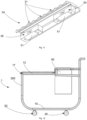
- the suspension structure 30 is shaped so as to present a serrated upper surface 32 forming said reception zones 31 as shown in the Figure 10 .
- the suspension structure 30 can be configured so as to present at least one suspension bar 34.
- the suspension bar 34 then comprises the measuring device 50 of the at least one container 90 as shown in Figure 11 .
- the suspension bar 34 is shaped to at least partially penetrate the at least one container 90, preferably to pass through the handle(s) 91, 92 for example of the at least one container 90. Consequently , the suspension bar 34 has a free end.
- the suspension bar 34 has a length dimension configured to suspend at least one, preferably at least two and advantageously at least three containers 90.
- the hinge 17 is advantageously located on the front part of the carriage 1.
- the Figure 15 shows that the suspension structure 30a of the first carriage 1a tilts upwards through the hinge 17 to make way for the non-inclined suspension structure 30b of a second carriage 1b.
- the at least one container 90 is removed from said carriage 1 by the front part of the carriage 1. In fact, it is sufficient to slide the at least one container 90 from the reception areas 31 towards the free end of the suspension bar 34 to remove the at least one container 90. The user then does not need to lift the at least one container 90 from its height to remove it from the cart 1.
- the carriage 1 comprises at least one tray 40 entirely suspended from the supporting structure 200.
- the tray 40 is entirely suspended advantageously by at least one rim 41 or 42, preferably by at least two rims 41,42, advantageously opposite one to the other.
- each rim 41, 42 includes at least one additional measuring device 43 for the weight of said suspended bin 40 and at least one product it contains.
- the additional device 43 is a type S sensor.
- the suspended bin 40 makes it possible to contain heavier and/or more bulky products such as products that cannot be placed in the at least one container 90 suspended by the suspension structure 30.
- the present invention then makes it possible to measure a parameter relating to the weight of heavy and/or bulky products. By “heavy”, we mean products whose weight is between 3 and 30 kg.
- the hanging bin 40 may include at least one opening 44 configured to accommodate at least the hanging bar 34 of at least one other cart having a hanging bar.
- the second carriage 1b can nest in the first carriage 1a until the tray of the second carriage 1b comes almost into contact with the tray 40 of the first carriage 1a.
- the suspension bar 34 when the suspension bar 34 is inclined upwards, it does not exceed the height corresponding to the gripping device 60.
- the suspension bar 34 is optionally articulated in rotation on the carriage 1 by means of a hinge.
- the suspended bin 40 can be removable from the carriage 1. This facilitates nesting in the case where the suspended bin 40 does not include at least one opening 44. In fact, it is then sufficient to the user to remove the suspended bin 40 to fit the cart 1 with another cart.
- THE figures 17 and 18 describe the interlocking of the first carriage 1a with a second carriage 2a and a third carriage 3a. Cart nesting can be achieved with a large number of carts.
- FIG. 33 illustrates an embodiment in which the suspension structure 30 is mounted to rotate around a horizontal axis. More precisely, the suspension structure 30 has a first arm 11 and a second arm 12 each having a proximal end articulated in rotation on the carriage 1, typically on the supporting structure 200. This rotational articulation can be ensured by a hinge 17.
- the first arm 11 and the second arm 12 each have a distal end which are mechanically linked to each other by a profile.
- the first arm 11, the second arm 12 and the profile thus define a contour, which can be open or closed.
- the first arm 11 and the second arm 12 are in contact with a stop 19 carried by the supporting structure 200.
- This stop 19 takes up at least part of the weight of the suspended containers 90 of the suspension structure 30.
- the first arm 11 and the second arm 12 are moved away from the stop 19 to be raised. For this, these arms 11, 12 are rotated around the axes on which they are mounted on the supporting structure 200.
- the cart 1 comprises at least one cylinder 18 configured to hold the suspension structure 30 in position when the suspension structure 30 is in storage configuration, at least when the suspension structure 30 does not suspend any container 90.
- the cylinder 18 has one end articulated in rotation on the supporting structure 200 and another end articulated in rotation on one of the arms 11, 12 or on a structure integral with one of these arms 11, 12.
- the carriage 1 comprises two cylinders 18, each of the cylinders being connected to one of the arms 11, 12.
- the suspension structure 30a of the first carriage 1a is adjusted in storage configuration so as to be nested at least partially with at least a second cart 2a having an identical suspension structure 30b set in storage configuration.
- the hinge 17 is located on the part rear of the carriage 1.
- the suspension structure 30a of the first carriage 1a and the suspension structure 30b of the second carriage 2b are tiltable upwards so as to allow the nesting of the first carriage 1a with the second carriage 1b. Nesting is possible until one of the supporting structure 200a, the suspension structure 30a of the first carriage 1a is in contact with one of the supporting structure 200b, the suspension structure 30b of the second carriage 1b .
- FIG 34 illustrates the nesting of several carts 1 illustrated in Figure 33 .
- the suspension structures 30 are raised so as to be placed in their storage configuration.
- the suspension structure 30 of a first carriage 1a then does not hinder the nesting of a second carriage 1b in this first carriage 1a.
- This embodiment allows a particularly high nesting rate, that is to say that the nesting distance is significant. This embodiment thus makes it possible to increase the compactness of the storage of a plurality of trolleys 1.
- the suspension structure 30 has a height dimension H which decreases along a direction corresponding to the direction of nesting 500 of the second carriage 1b in the first carriage 1a so as to authorize nesting at the less partially of the suspension structure 30b of the second carriage 1b in the suspension structure 30a of the first carriage 1a.
- the second carriage 2b can be nested at least partially in the first carriage 1a.
- the suspension structure 30 comprises at least a first arm 11 and a second arm 12 extending respectively in a first direction and a second direction, the first direction and the second direction being concurrent, and on both sides the other of said carriage 1.
- One of the first arm 11 and the second arm 12 then advantageously comprises the measuring device 50.
- the first arm 11 and the second arm 12 are shaped so as to each present at least two horizontal portions 13 and at least one vertical portion 14 separating the two horizontal portions 13, so as to form a staircase structure for example and thus to allow the nesting of said carriage 1 at least in part with at least one other carriage having an identical suspension structure by nesting the suspension structure 30a of said first carriage 1a with the suspension structure 30b of said at least one second carriage 1b , preferably by nesting the first 11a and the second arm 12a of said carriage 1a respectively with the first 11b and the second arm 12b of said at least one other carriage 2b.
- the vertical portions 14 are intended to partially support at least the at least one container 90 and the at least one product.
- the at least one measuring device 50 is then carried by at least one horizontal portion 13.
- the nesting distance corresponds to the length of the shortest horizontal portion 13 of the first arm 11 and second arm 12 combined.
- the user can easily nest the cart 1 with another cart 1.
- This nesting mode makes it possible to achieve nesting distances of the order of 23% of the length of a cart 1.
- the nesting distance is of the order of 300 mm. This then allows a considerable saving of space for storing trolleys when not in use. This increases the number of nestable trolleys in a defined space.
- the carriage 1 as described in the invention is not bulky. Consequently, the presence of the suspension structure 30 does not disrupt the ability of said carriage 1 to be nested.
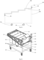
- the carriage 1 comprises at least one frame 100 carried by the chassis 10.
- the frame 100 is shown on the Figure 31 For example.
- the carriage 1 is configured so that when a force applied by a user on the frame 100 has a vertical component, this vertical component is transmitted from the frame 100 to the chassis 10 then to the ground without being transmitted to the supporting structure 200 and to the suspension structure 30.
- This allows no external element to disturb the measurement carried out by the measuring device 50 of the parameter relating to the weight of the at least one container 90 and the at least one product.
- external element we mean for example the support of a person on the suspension structure 30 of the trolley 1.
- the presence of the frame 100 allows the user or another person to lean on said frame 100 without disturbing the measurement carried out by the measuring device 50.
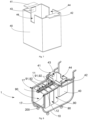
- the frame 100 is configured to define an envelope enclosing an internal volume.
- the reception zones 31 of the suspension structure 30 are located within said internal volume.
- the suspension structure 30 is advantageously not accessible for the support of a person. We then avoid any risk of disturbances in the measurement of the parameter relating to weight.
- the measuring system is then equipped with high precision and high reliability.
- the supporting structure 200 is also located inside the internal volume. For this purpose, the supporting structure 200 is not easily accessible for the user or another person to support it.
- the first arm 11 and the second arm 12 are curved so as to allow the nesting of the first and second arms 11b, 12b of a second carriage 1b in the first and second arms 11a, 12a of the first carriage 1a.
- the suspension structure 30 is configured so as to authorize the variation of said length L2. Indeed, it is possible to vary the length L2 in order to adapt the trolley 1 to the quantity of shopping carried out by the user.
- the length L2 of the suspension structure 30 can be adjusted by the user before the start of the races.
- the user can also change the length L2 of the suspension structure 30 when the at least one container 90 is already suspended.
- the suspension structure 30 can then be reduced by at least 70% of its initial length L2. It facilitates thus the storage of trolleys and this allows a greater number of trolleys to be nested in a limited space.
- the first arm 11 and the second arm 12 comprise telescopic portions 16, which are each configured to have an deployed configuration and a folded configuration.
- Figure 25 shows the deployed configuration in which said first 11 and second 12 arms are configured to partially support at least the at least one container 90 suspended from the suspension structure 30.
- Said first 11 and second 12 arms support in particular the at least a container 90 by the reception zones 31 arranged on the side face 32 of the suspension structure 30.
- the figures 26 and 27 show the folded configuration of the telescopic portions 16, in which the first carriage 1a is able to be fitted with at least one second carriage 1b having an identical suspension structure 30b.
- the telescopic portion 16a of a first carriage 1a cooperates with the telescopic portion 16b of a second carriage 1b so that at least one reception zone 31 carrying the respective measuring device 50 of each telescopic portion 16a, 16b comes in contact with each other.
- This makes it possible to increase the nestability of a first carriage 1a with a second carriage 1b and thus increase the nestability of a series of carriages. Storage of trolleys then takes up less space.
- the suspension structure 30 has at least one side face 32 so that the reception zones 31 of the suspension structure 30 are located on the at least one side face 32.
- the zones d The reception 31 can be handles, preferably half-moon, or any abutment surface allowing the user to hang, for example, handles or handles of the at least one container 90.
- the reception zones 31 are hooks, attached directly to the suspension structure 30.
- the force sensor 51 can be a button type sensor directly integrated into the reception zones 31. This makes it possible to avoid the weighing of the suspension structure 30 and this makes it possible to directly weigh the at least one container 90 and the at least one product.
- the suspension bar 34 can optionally have a telescopic portion 16.
- the suspension structure 30 is held on the supporting structure 200 at the rear of the carriage 1.
- the suspension structure 30 has at least one free end at the front of the carriage 1.
- the width I2 of the suspension structure 30 is shaped to decrease along a direction corresponding to the direction of nesting 500 of said carriage 1 in another carriage so as to authorize the nesting at least partially of the carriage 1 in another cart having an identical suspension structure.
- the first arm 11 and the second arm 12 of the suspension structure 30 are held to the supporting structure 200 at the level of the rear part of the carriage 1.
- the first arm 11 and the second arm 12 are united with each other means of at least one telescopic securing portion 15.
- the first 11 and second 12 arms are advantageously secured to each other at their free ends, which are located at the front of the carriage 1.
- the telescopic portion securing device 15 is configured to present an deployed configuration and a folded configuration.
- FIG. 28 shows the deployed configuration, in which the first arm 11 and the second arm 12 are in a position away from each other.
- the first arm 11 and the second arm 12 are preferably parallel to each other and the telescopic securing portion 15 is configured in its maximum length.
- Said first 11 and second 12 arms support in particular the at least one container 90 by the reception zones 31 arranged on the side face 32 of the suspension structure 30.
- THE figures 29 And 30 show the folded configuration, in which the first arm 11 and the second arm 12 are in a position close to each other.
- the first arm 11 and the second arm 12 are concurrent with each other.
- the first 11 and second 12 arms being held to the supporting structure 200 at the rear of the carriage 1, when the telescopic securing portion 15 is folded, the first 11 and second 12 arms approach one of the 'other at the front of the carriage 1 so as to become concurrent with each other.
- the telescopic securing portion 15a of the first carriage 1a and the telescopic securing portion 15b of the second carriage 1b are preferably each in a folded configuration.
- first 11 and second 12 arms of the second carriage 1b are capable of being inserted into the first 11 and second 12 arms of the first carriage 1a.
- the cart 1 comprises at least one receptacle 80 intended to receive at least one product.
- the receptacle 80 is advantageously supported by the chassis 10.
- the parameter relating to the weight of the receptacle 80 and the at least product it contains is measured by the measuring device 50.
- the receptacle 80 has at least one side wall 81 or 82 configured to be movable in rotation around an axis of rotation 83.
- the axis of rotation 83 is preferably horizontal, so that the wall 81 or 82 can move from a configuration in which the wall 81 or 82 forms a container with the other walls of the receptacle 40 to a position in which said carriage 1 is nested at least partially with at least one other carriage having an identical receptacle.
- the receptacle 80b of the second carriage 1b is inserted into the receptacle 80a of the first carriage 1a in the following manner: the side wall 81b of the second carriage 2b pushes the side wall 82a of the first carriage 1a so as to generate the rotation of the side wall 82a around of the axis of rotation 83.
- the receptacle 80b thus penetrates the receptacle 80a until the side wall 81b is in contact with the side wall 81a.
- the carriage 1 comprises at least one frame 100 carried by the chassis 10.
- the frame 100 advantageously matches at least part of the contour of the receptacle 80.
- the presence of the frame 100 allows the user or another person to lean on said frame 100 without disturbing the measurement carried out by the measuring device 50.
- the first and second arms 11, 12 of the suspension structure 30 are articulated in rotation on the supporting structure 200, around a substantially horizontal axis.
- the first and second arms 11, 12 are advantageously tiltable upwards.
- This rotation can be carried out by means of the hinge 17 making a pivot connection along a substantially horizontal axis.
- the hinge 17 is advantageously carried on the front part of the carriage 1.
- the first arm and the second arm 11, 12 are each in contact with at least one stop 19, carried by the supporting structure 200 preventing rotation of the suspension structure 30 under the effect of gravity.
- the storage configuration as shown on the figures 36 and 37 allows the nesting at least partially of said first carriage 1 with another carriage 1 having an identical suspension structure in the storage position, the suspension structure 30 being at a distance from the stop 19.
- the force sensor 51 can be in contact with at least one hook, which is used to suspend said containers 90.
- the force sensor 51 can for example be of the “integrated button” type.
- the user can directly suspend the containers 90 on at least one hook, intended for this use.
- the first 11 and second 12 arms can advantageously comprise at least one force sensor 51 of the cantilever type.
- the rolling device 20 may comprise a device for measuring at least one parameter relating to the weight of the at least one container. This allows the entire cart, as well as the containers, to be weighed directly.
- the suspension structure 30 comprises at least two containers 300, preferably three containers 300 as they are represented on the figures 39 to 44 . Following the description, containers can also be referred to as bins or containers.
- At least two containers forming adjacent bins or boxes are nestable at least in part.
- the containers are suspended.
- the containers are at least two by two partially nested.
- At least a portion of a first container is then housed in a second container which is adjacent to it.
- the second container is located closer to the rear of the cart than the first container.
- container 300a completely houses containers 300b and 300c.
- the nesting of a first cart in a second cart causes the containers 300 of the second cart to move and fit together at least two by two.
- this movement is sliding.
- the direction 4 of sliding and the direction of normal advance 3 of the carriage are contained in the same plane.
- the normal cart forward direction 3 extends the forward direction when the user pushes the cart forward without making a turn. This direction 3 is referenced in figures 49 And 52 .
- At least one of the containers is slidably mounted in the cart and relative to at least one other container.
- Each container 300 is formed of a bottom wall 303 and at least two side walls 304.
- the bottom wall 303 has a length dimension Lpf, which corresponds to the distance separating the two side walls 304 of each container 300.
- the dimensions Lpf1-Lpf3 of each container are illustrated in figure 42 .
- the two side walls 304 can be perpendicular to the bottom wall 303 and oppose each other. More generally, the two side walls 304 extend from the bottom wall 303 and define with the latter a “U” shape whose branches form a right angle or an angle greater than 90° with the bottom wall 303.
- each container 300 remains open and has at least one open surface, perpendicular to the side walls 304.
- the side walls 304 have edges 3040.
- three edges among the edges 3040 form a U and delimit the at least one open surface.
- each container 300 has at least two open surfaces, opposite each other so that each container 300 is in the shape of a U.
- the rear container 300a it that is to say the one positioned furthest to the rear of the carriage 1, has a bottom. This bottom defines a third side wall 305 connecting the two other side walls 304 and then leaving a single open surface to the rear container 300a.
- each container 300 has a third side wall 305.
- the figures 48 to 50 illustrate in detail the suspension of the containers 300 from the suspension structure 30.
- the containers 300 are entirely suspended from the suspension structure 30, advantageously by at least one rim 41 or 42 each forming a reception area, preferably by at least two edges 41,42, advantageously opposite each other.
- the edges 41, 42 are not fixed to the suspension structure 30, but form a sliding connection with the suspension structure 30.
- each edge 41, 42 forms a reception area configured to support or entirely suspend a container 300a -300c.
- each rim 41, 42 forms a slide which cooperates in sliding with a rail 306 of the suspension structure 30 to guide and support the container in its translation relative to the carriage.
- Rail 306 is clearly identifiable in figures 50 .
- the containers 300 can translate along the suspension structure 30.
- the containers 300 translate along an axis corresponding to the direction 4 of nesting 500 of the carriage 1.
- the rail 306 is integral with or cooperates with at least one measuring device 50 so that the weight of the containers and the articles placed in the containers are transferred to the rail 306 and are captured by the device measuring 50.
- the suspension structure 30 comprises at least two rails 306, the rails 3 being arranged in parallel manner and carried by each side of the carriage.
- the three containers 300 are advantageously arranged in the following manner: they are aligned in the direction 4 of nesting 500 of the carriage 1.
- the rear container 300a has the largest open surface, that is to say the bottom wall 303a of the rear container 300a has the largest dimension in length Lpfa.
- the front container 300c that is to say, the one positioned furthest at the front of the cart 1 has the smallest open surface, that is to say the bottom wall 303c of the front container 300c has the largest small dimension in length Lpfc.
- the intermediate container 300b that is to say that positioned between the front container 300c and the rear container 300a, has an open surface between the open surface of the front container 300c and the open surface of the rear container 300a, c that is to say, the bottom wall 303b of the intermediate container 300b has a length dimension Lpfb between Lpfa and Lpfc.
- Lpfb length dimension between Lpfa and Lpfc.
- the direction 4 of sliding of the containers is inclined relative to the horizontal.
- direction 4 of sliding of the containers and the horizontal i.e. the direction of advance 3 of the carriage on a single plate together define an angle alpha.
- This angle is illustrated in figures 49 And 50 .
- This direction 4 is inclined towards the front.
- the end of the rail 306 closest to the front of the cart is closer to the ground than the end of the rail closest to the rear of the cart.
- This inclination, as well as the supporting structure 30, are configured so that the containers 300 slide towards the front of the cart under the effect of gravity.
- the containers are empty or support articles, their weight drives them towards the front of the cart and causes their deployment, that is to say when they move apart.
- Each side wall 304, 305 and bottom wall 303 of each container 300 has an internal surface and an external surface. According to a more than advantageous mode, there is a spacing between the external surface of the side walls 304 of the nested container and the internal surface of the side walls 304 of the nested container. This spacing can be between 0 and 50 mm. Likewise, there is a spacing between the outer surface of the bottom wall 303 of the nested container and the inner surface of the bottom wall 303 of the nested container. This spacing can be between 0 and 50 mm.
- the figures 49 And 50 show the positioning of the measuring device 50 which is carried by the suspension structure 30 in the same way as for the embodiment shown in Figure 19 .
- At least one container and preferably the intermediate container 300b and the rear container 300a each have at least one guide rail 302, preferably two rails.
- Each rail 302 has the role of facilitating the guiding of the nesting container in the nested container. It also serves to stabilize the configuration of the containers 300.
- the rails are preferably arranged on the internal surface of the side walls 304 of the containers 300, preferably halfway up the containers 300. More generally, it is the nested container which has the rail 302.
- the rail 302 is directed in the direction 4 of nesting 500 of the containers 300. Another advantage conferred on the rail 302 is to allow better weight distribution.
- the rail 302 carried by the intermediate container 300b translates on the rail 302 carried by the rear container 300a.
- the rail 302 carried by the intermediate container 300b exerts support on the rail 302 carried by the rear container 300a.
- the rail 302 carried by the rear container 300a then supports at least part of the weight supported by the intermediate container 300b. The weight is then better distributed between the intermediate container 300b and the rear container 300a. This then facilitates the handling of the cart 1 when the user is shopping.
- these rails 302 or slides have at least one of their ends a stop 3021.
- This stop is for example formed by the end of a groove or a slot which defines the rail 302 and which is formed in the internal face of the container.
- this stop carried by the second carriage comes into contact with the container located furthest in front of the first carriage and then causes the sliding of this front container, along the rail 306 (that is to say in the direction 4 of sliding) and towards the rear of the first carriage.
- This front container moves until it comes into contact with the container adjacent to it and causes the latter in turn to slide towards the rear of the first carriage.
- This stop carried by the second carriage may be a bottom wall of the container of the second carriage located furthest back.
- this stop can be carried by another element of the second carriage.
- the container placed furthest back is configured to move towards the rear of the cart when a force is applied to it typically, when the cart is nested in another cart.
- this container returns to its rest position by simple gravity.
- This backward movement has a travel preferably between 5 and 30 centimeters. It makes it possible to further improve the nesting rate of two trolleys one inside the other.
- FIG. 39 to 55 presents two possible configurations for the containers 300: a configuration called deployment configuration illustrated in figures 39 to 44 and a configuration called retraction configuration illustrated in figures 45 to 47 .
- the deployment configuration is the one that the user will use when carrying out their shopping. Indeed, it is the configuration which makes it possible to have a large volume to accommodate all of the additional containers 90 such as a bag or sachet.
- the at least one additional container 90 can be suspended by the reception areas 31 located on the internal surface of the side walls 304 of the containers 300.
- another possible option for the user is to directly place the at least an additional container 90 or directly the product on the bottom wall 305, that is to say the bottom wall of the rear container 300a of the first carriage 1a.
- the invention has the advantage of proposing an opening on the container before 300c, an opening which corresponds to the open surface described above.
- the front container 300c has a front stop 301 as shown in the figure 44 .
- the front stop 301 of the first carriage or its stop when there is no stop 301 comes into contact with the bottom wall 305 of the second cart.
- This bottom wall 305 acts as a stop to stop the movement of the stop 301 and the container 300c.
- this abutment causes the relative sliding of the containers of the first cart and their telescopic or Russian doll-like nesting.
- FIGS 51 to 54 For example.
- the containers of the second cart are shown nested inside each other to make this embodiment clear.
- this container configuration will be possible if the second cart is itself nested in the third cart (or if the user pushes the containers towards the rear of the cart, which is not a normal case of using the cart).
- This embodiment of retracting or nesting the carts is particularly simple since it is done automatically when the user nests a cart into another cart. Furthermore, this embodiment does not require any actuator. It is therefore particularly easy to use and robust.
- the front stop 301 is parallel to the third side wall 305 of the rear container 300a. According to a non-limiting example, it extends perpendicular to the two side walls 304 of the front container 300c and connects the two side walls 304 of the front container 300c.
- the stop 301 has a height dimension less than half the height dimension of the front container 300c.
- the retraction configuration is the one that the user will favor for storing the cart 1. Indeed, as illustrated on the figures 51 to 55 , when the front container 300c and the intermediate container 300b are nested in the rear container 300a, all of the containers 300 occupy a volume substantially three times smaller than when the cart 1 is in deployment configuration. This allows a considerable saving of space when storing trolley 1. Considering then trolleys of standard dimensions of the order of magnitude 1300 mm ⁇ 650 mm, it is possible to nest 36 trolleys in 3 separate rows of nesting, i.e. 12 carts per row in standard dimensions of a parking space.
- the suspension structure 30 also has a height dimension H which decreases along a direction corresponding to the direction of nesting 500 of the second carriage 1b in the first carriage 1a so as to authorize the at least partially interlocking of the structure suspension 30b of the second carriage 1b in the suspension structure 30a of the first carriage 1a.
- the second carriage 1b can be nested at least partially in the first carriage 1a. The nesting is then advantageously stopped when the suspension structure 30 of the first carriage 1a and the suspension structure 30 of the second carriage 1b rub against each other sufficiently and thus slow down the nesting until the second carriage 1b stops.
- the cart will be configured so that the container located furthest behind the cart can slide along the rail 306 when a force is applied to it, typically when the cart is nested in a another cart. This further reduces the volume occupied by several nested trolleys.
- Said frame 100 can also be present in the embodiment illustrated in figures 39 to 55 .
- the presence of the frame 100 allows the user or another person to lean on said frame 100 without disturbing the measurement carried out by the measuring device 50.
- figures 48 and 49 for example, it clearly appears that the suspension structure 30 is distinct from the frame 100.
- the frame 100 has a shape which hides the suspension structure 30, typically the rail 306 for the user. The latter therefore cannot or cannot easily access the suspension structure, typically the rail 306, for example to lean on it. The user, on the contrary, will come into contact and lean on the frame 100.
- the suspension structure 30 forms a rail 306 which extends under a profile of the frame 100.
- this frame profile 100 forms an “L” or an “U” inverted or inclined and open towards the interior trolley.
- this profile frame 100 forms a tube whose section defines a closed contour 101 with the exception of an opening 102, which extends longitudinally and which is configured to allow a mechanical connection between the containers and the guide rail.
- this opening 102 forms a slot which extends over all or part of the length of the frame profile 100 and which allows the passage of at least one rim 41, 42 for each container.
- the contour 101 and the opening 102 are referenced in figure 50 .
- the rail 306 of the suspension structure 30 is housed inside the frame profile 100.
- the rail 306 of the suspension structure 30 extends along this volume. This rail 306 is thus protected. At the very least, a user cannot lean on this suspension structure 30. This makes it possible to avoid distorting the measurement of the weight of the articles contained in the cart. This therefore makes it possible to resolve the problem of improving the reliability and precision of measuring the weight of the items contained in the cart. Furthermore, this makes it possible to improve the safety of the carriage by preventing a user from interfering with the slides on the rail 306, for example by trapping their fingers.
- all the embodiments describe a suspension structure configured to authorize the nesting of the cart in another cart having an identical suspension structure.
- the containers are delimited by solid walls, for example metal or plastic. According to another embodiment, only one, or several, or even all of the walls are formed of a mesh structure or an openwork structure as illustrated in figure 2 .
- the containers or containers are rigid. They cannot be deformed manually.
- the plurality of containers or containers is replaced by a single container or deformable container.
- this deformable container is made at least partly from fabric, and preferably entirely from fabric. It is configured to be compressed to selectively switch from an deployed configuration to a retracted configuration. In the deployed configuration it offers a first reception volume of articles deposited by the user. In the retracted configuration it does not accommodate items or has a lower reception volume than in the deployed configuration.
- the transition from the deployed configuration to the retracted configuration is done by nesting the cart into another cart.
- the fabric container can be provided with privileged deformation zones.
- privileged deformation zones can for example include preformed zones and configured to facilitate deformation. These may for example be bellows made of fabric or elastomer, rubber or for example.
- the deformable container can have edges provided with rings or eyelets which cooperate with a guide element such as a rail, a rod or a guide cable, such as for example the rail 306 illustrated in figure 50 .
- this guide element is inclined relative to the horizontal approaching the ground towards the front of the carriage.
- the front part of the deformable container moves by gravity towards the front of the cart.
- a cart having the same frame 100 and the same suspension structure 30 can accommodate different types of containers.
- one or more fixed rigid containers, one or more sliding and telescopic rigid containers, one or more deformable containers can be selectively mounted on the same trolley.
- the cart 1 advantageously has a container 40 and preferably a single container 40.
- This container 40 comprises a front part 103 and a rear part 104.
- the rear part 104 corresponds to the part of the container 40 closest to the gripping device 60 , the front part 103 being located opposite the rear part 104.
- the chassis 10 also includes a part front 105 and a rear part 106.
- the rear part 106 corresponds to the part of the chassis closest to the gripping device 60, the front part 105 being located opposite the rear part 106.
- the front part 103 of the container 40 has a width dimension 103a greater than the width dimension 104a of the rear part 104 of the container 40.
- the front part 105 of the chassis 10 has a width dimension 105a less than the width dimension 106a of the rear part 106 of the chassis 10.
- the cart 1 is configured to partially receive at least one other cart 1b in storage configuration and advantageously to be received at least partially by the other cart 1b.
- the front part 103 of the container 40 is wider in order to be able to come from either side of the rear part 104 of the container 40 of another cart 1b in storage configuration.
- the front part 105 of the chassis 10 is narrower in order to be able to come into the rear part 106 of the chassis 10 of another cart 1b in storage configuration.
- the pendant container 40 of the front carriage 1b which penetrates inside the container 40 of the rear carriage 1a.
- the chassis 10 of the rear carriage 1a which enters at the inside the chassis 10 of the front carriage 1b.
- the carriage 1a of the present invention is configured to present a part which fits into a part of another carriage 1b and to present another part which surrounds another part of another carriage 1b.
- the suspension structure 30 comprises at least one suspension bar 34, at least one measuring device 50 comprising at least one force sensor 51, and at least one attachment 56 of the measuring device 50 to the frame 100 , and preferably frame 100.
- the suspension structure 30 has a height dimension H which decreases along a direction corresponding to the direction of nesting of said carriage 1 in another carriage 1b so as to authorize nesting at least partially of the carriage 1 in another carriage 1b having a suspension structure 30 identical to the suspension structure of said carriage 30.
- the frame 100 has a height dimension which decreases along a direction corresponding to the direction of nesting of said carriage 1 in another carriage 1b so as to authorize the nesting at least partially of the carriage 1 in another carriage 1b having a suspension structure identical to the suspension structure of said carriage 1.
- the measuring device 50 is inserted into the frame 100, preferably is arranged between two parts of the frame 100.
- the frame 100 can comprise a plurality of parts 101, 102.
- one or several measuring devices 50 can be arranged between different parts of the plurality of parts of the frame 100.
- the frame 100 comprises a first part 101 and a second part 102.
- the measuring device 50 is located between the first part 101 and the second part 102 so as to have a on the other hand to secure the two parts together, and on the other hand to suspend the force sensor 51 so that any support on the frame 100 cannot interfere with a weight measurement.
- the front part 103 of the container 40 advantageously comprises a valve 400 disposed at the front of the carriage 1.
- the valve 400 forms a wall of the container 40.
- This valve 400 is configured to lower when the carriage 1 fits with another carriage 1b, preferably when the front part 103 of the container 40 receives the rear part 104 of the container 40 of another carriage 1b.
- the valve 400 selectively presents two configurations.
- a first configuration corresponds to a so-called raised configuration in which the valve 400 extends mainly vertically
- the second configuration corresponding to a so-called lying configuration in which the valve 400 extends mainly horizontally.
- the valve 400 comprises at least one hinge element 402.
- This hinge element 402 comprises an axis of rotation, preferably horizontal.
- This hinge element 402 advantageously comprises at least one return element configured to maintain the valve in raised configuration when the carriage 1 is not nested with another carriage 1b, preferably is not nested around another of the container trolley 1b.
- the frame 100 comprises covers 35 arranged above the measuring devices 50. These covers 35 are supported on the frame 100 so that when a force having a vertical component is applied to the frame 100 or to the cover 35, this force is transmitted to the supporting structure 200 then to the chassis 10 so that this force cannot disturb the measuring device(s) 50, preferably cannot disturb the weight measurement(s) carried out by the device(s). measuring 50.
- the carriage 1 comprises at least 4 measuring devices 50.
- Each arm of the carriage 11, 12 preferably carries two measuring devices 50. These measuring devices 50 will be described more precisely later.
- the carriage 1 comprises a gripping device 60 and a display device 70 as described above.
- the cart 1 thus comprises at least one container 40 suspended from the frame 100 through four measuring devices 50.
- this container 40 comprises two parts, a front part 103 and a rear part 104.
- the front part 103 comprises a width dimension 103a greater than the width dimension 104a of the rear part 104.
- the front part 103 of the container 40 comprises the valve 400 described previously.
- the rear part 104 of the container 40 comprises at least one rear wall 403.
- the front part 103 of the container 40 is suspended from the frame 100 through two measuring devices 50.
- the front part 103 of the container 40 is suspended from the first arm 11 of the carriage 1 by a measuring device 50 through a suspension bar 34, and to the second arm 12 of the carriage 1 by another measuring device 50 through another suspension bar 34. It is the same for the rear part 104 of the container 40.
- a block comprising an electric battery 54 configured to electrically power all of the electrical elements of the cart 1.
- This block is advantageously arranged under the container 40 so that the center of gravity is the lowest possible.
- FIG 57 is a profile view of the carriage 1 illustrated in figure 56 .
- the block 54 comprising a coaxial finger 53.
- This coaxial finger is configured to abut against a stop carried by the container 40.
- the stop limits the movement and therefore the swing of the container 40.
- the stop is formed by an opening into which the coaxiality finger 53 is inserted.
- the coaxiality finger 53 is configured to come to rest on the edge of the opening carried by the suspended container 40 so as to limit the swinging of said container 40 suspended.
- the coaxiality finger 53 can be replaced or include an additional measuring device 53.
- This additional measuring device 53 is intended to support at least part of the container 40 and its contents, and preferably intended to measure the weight of the container 40 and its contents.
- FIG 58 is a top view of a carriage 1 as illustrated in figure 56 and 57 .
- the front part 105 of the carriage 1 is narrower than the rear part 106 of the carriage 1 so as to allow the nesting of said carriage 1 in at least part of another carriage 1b.
- the front part 103 of the container 40 is wider than the rear part 104 of the container 40 so as to allow the nesting of said cart 1 around at least part of another cart 1b, preferably to allow the front part 103 of the container 40 of the cart 1 to fit together around the rear part 104 of the container 40 of the other cart 1b.
- FIG 59 is an enlargement of a measuring device 50 placed under a cover 35 and between a first part 101 of the frame 100 and a second part 102.
- the measuring device 50 is connected to at least part of the container 40 by a suspension bar 34.
- the use of a cover 35 is clever, because it only rests on the frame 100, and is not in direct mechanical contact with the measuring device 50, so that any force applied to the cover 35 and having a vertical component is neither transmitted to the measuring device 50, nor to the container 40, but directly to the frame 100, then to the supporting structure 200 and finally to the chassis 10.
- FIG. 60 illustrates the same enlargement as that of the figure 59 with the cover 35 removed.
- the measuring device 50 comprising a force sensor 51.
- This force sensor 51 is secured to the first part 101 of the frame 100 and the second part 102 of the frame 100. This connection is ensured by connection bars 55 and by a hook 56 of the force sensor 51. This hook 56 secures the force sensor 51 to the securing bars 55.
- This connection is clever, because it prevents any force applied to the frame 100 from being able to disrupt the measurement of the weight of the container 40 and its contents.
- the introduction of the measuring device 50 into the structure of the frame 100 allows for significant space saving and better ergonomics.
- This force sensor 51 is also integral with at least part of the container 40 preferably through a suspension bar 34.
- the frame 100 comprises the securing bars 55
- Figure 61 is a view following the figure 60 , in which the force sensor 51 is separated from the frame 100 for the sake of clarity in order to illustrate the mechanical assembly of the measuring device 50 according to a clever embodiment.
- the container 40 is suspended from the measuring device 50, in particular from the force sensor 51, via the suspension bar 34.
- the container 40 is thus completely uncorrelated from the forces which may or may not be applied on the frame 100 of the carriage 1.
- the frame 100 comprises at least one opening 107, which can take the form of a through opening, a recess or a groove.
- the measuring device 50 is arranged, preferably entirely housed, inside the opening 107 of the frame 100.
- FIG 62 illustrates a carriage 1a nested around another carriage 1b.
- the cart 1a comprises a container 40 having a front part 103 wider than its rear part 104 so as to cooperate with the rear part 104 of another cart 1b identical to the cart 1a and thus so as to come nest around the rear part 103 of the container 40 of the other carriage 1b.
- the rear part 104 of the container 40 of the other carriage 1b therefore fits into the front part 103 of the container 40 of the carriage 1a.
- the valve 400 of the carriage 1a is swapped in its lying configuration by the rear part 104 of the container 40 of the other carriage 1b.
- the rear part 104 of the container of a cart 1 comprises a rear wall 403.
- the figure 63 schematically illustrates a top view of the interlocking of the carriage 1a with the other carriage 1b.
- front part 103 of the container 40 of the cart 1 surrounds at least part of the rear part 104 of the container 40 of the other cart 1b, and that the front part 105 of the chassis 10 of the cart 1a fits into place in at least part of the rear part 106 of the chassis of the other carriage 1b.
- the present invention thus makes it possible to simply, efficiently and reliably fit together two trolleys each equipped with at least one device for measuring the weight of a container and its contents.
Claims (15)
- Wagen (1), zum Beispiel für einen Supermarkt, umfassend:- mindestens ein Fahrgestell (10), das von mindestens drei Auflageorganen gestützt wird, die dafür konfiguriert sind, den Wagen (1) isostatisch auf einem Boden abzustützen, wobei mindestens zwei der mindestens drei Organe jeweils mindestens eine Rollvorrichtung (20) umfassen,- eine Tragstruktur (200), die vom Fahrgestell (10) gestützt wird,- eine von der Tragstruktur (200) gestützte Aufhängungsstruktur (30), die dafür konfiguriert ist, mindestens einen Behälter (40, 90, 80, 300), in dem mindestens ein Produkt platziert werden soll, aufzuhängen, wobei der Wagen (1) so konfiguriert ist, dass der mindestens eine Behälter (40, 90, 80, 300) vollständig an der Aufhängungsstruktur (30) aufgehängt ist,- eine Greifvorrichtung (60), die dazu bestimmt ist, vom Benutzer gegriffen zu werden, um den Wagen (1) zu bewegen, dadurch gekennzeichnet, dass- der Wagen (1) mindestens eine Messvorrichtung (50) umfasst, die mindestens zum Teil von der Aufhängungsstruktur (30) getragen wird und dazu bestimmt ist, mindestens einen Parameter, der sich auf das Gewicht des mindestens einen Behälters (40, 90, 80, 300) bezieht, zu messen, wenn der Behälter an der Aufhängungsstruktur (30) aufgehängt ist,- die Aufhängungsstruktur (30) des Wagens (1) dafür ausgestaltet ist, mit der Aufhängungsstruktur (30) eines anderen Wagens (1) so zusammenzuwirken, dass sie das mindestens teilweise Einschieben des Wagens (1) in den anderen Wagen (1) durch Zusammenwirken der Aufhängungsstruktur (30) des Wagens (1) mit der Aufhängungsstruktur (30) des anderen Wagens (1) zu ermöglicht.
- Wagen (1) nach dem vorstehenden Anspruch, wobei die Messvorrichtung (50) vollständig von der Aufhängungsstruktur (30) getragen wird.
- Wagen (1) nach einem der vorstehenden Ansprüche, wobei die Messvorrichtung (50) mindestens einen Kraftsensor (51) umfasst, der dazu bestimmt ist, den Parameter, der sich auf das Gewicht des mindestens einen Behälters (40, 90, 80, 300) und des mindestens einen Produkts, das dieser enthält, bezieht, zu messen, wobei der Kraftsensor (51) vorzugsweise einen Dehnungsmessstreifen umfasst.
- Wagen (1) nach einem der vorstehenden Ansprüche, der so konfiguriert ist, dass, wenn eine Kraft, die von einem Benutzer auf die Greifvorrichtung (60) ausgeübt wird, eine vertikale Komponente aufweist, diese vertikale Komponente von der Greifvorrichtung (60) auf das Fahrgestell (10) und dann auf den Boden übertragen wird.
- Wagen (1) nach einem der vorstehenden Ansprüche, der mindestens einen Rahmen (100) umfasst, der vom Fahrgestell (10) getragen wird, wobei der Rahmen (100) dafür konfiguriert ist, dass, wenn eine Kraft, die eine vertikale Komponente aufweist, von einem Benutzer auf den Rahmen (100) ausgeübt wird, diese vertikale Komponente vom Rahmen (100) auf das Fahrgestell (10) und dann auf den Boden übertragen wird, ohne auf die Aufhängungsstruktur (30) übertragen zu werden.
- Wagen (1) nach dem vorstehenden Anspruch, wobei die Messvorrichtung (50) am Rahmen (100) aufgehängt ist.
- Wagen nach einem der vorstehenden Ansprüche, der mindestens einen Behälter (40, 90, 80, 300) umfasst, in dem mindestens ein Produkt platziert werden soll.
- Wagen (1) nach dem vorstehenden Anspruch, wobei der mindestens eine Behälter (40, 300a, 300b) starr ist, das heißt nicht von Hand verformt werden kann.
- Wagen (1) nach einem der zwei vorstehenden Ansprüche, wobei der Behälter (40, 90, 80, 300) fest mit dem Wagen (1) verbunden ist, vorzugsweise nur über eine oder mehrere Messvorrichtungen (50).
- Wagen nach einem der drei vorstehenden Ansprüche, wobei die Aufhängungsstruktur (30), der mindestens eine Behälter (40, 80, 300) und das Fahrgestell (10) des Wagens (1) dafür ausgestaltet sind, so mit der Aufhängungsstruktur (30), dem mindestens einen Behälter (40, 80, 300) und dem Fahrgestell (10) eines anderen Wagens (1) zusammenzuwirken, dass sie das mindestens teilweise Einschieben mindestens eines Teils des Wagens (1) in das Innere mindestens eines Teils des anderen Wagens (1) durch Zusammenwirken der Aufhängungsstruktur (30), des mindestens einen Behälters (40, 80, 300) und des Fahrgestells (10) des Wagens (1) mit der Aufhängungsstruktur (30), dem mindestens einen Behälter (40, 80, 300) und dem Fahrgestell (10) des anderen Wagens (1) ermöglichen.
- Wagen (1) nach einem der vier vorstehenden Ansprüche, wobei die Aufhängungsstruktur (30), der mindestens eine Behälter (40, 80, 300) und das Fahrgestell (10) des Wagens (1) dafür ausgestaltet sind, so mit der Aufhängungsstruktur (30), dem mindestens einen Behälter (40, 80, 300) und dem Fahrgestell (10) eines anderen Wagens (1) zusammenzuwirken, dass sie das mindestens teilweise Einschieben mindestens eines Teils des anderen Wagens (1) in das Innere mindestens eines Teils des Wagens (1) durch Zusammenwirken der Aufhängungsstruktur (30), des mindestens einen Behälters (40, 80, 300) und des Fahrgestells (10) des anderen Wagens (1) mit der Aufhängungsstruktur (30), dem mindestens einen Behälter (40, 80, 300) und dem Fahrgestell (10) des Wagens (1) ermöglichen.
(40, 80, 300). - Wagen (1) nach einem der vorstehenden Ansprüche, wobei das Fahrgestell (10) einen vorderen Teil (105) und einen hinteren Teil (106) aufweist, wobei der vordere Teil (105) eine erste Breitenabmessung (105a) aufweist, wobei der hintere Teil (106) eine zweite Breitenabmessung (106a) aufweist, wobei die erste Breitenabmessung (105a) kleiner ist als die zweite Breitenabmessung (106a).
- Wagen (1) nach dem vorstehenden Anspruch, wobei der vordere Teil (105) des Fahrgestells (10) dafür konfiguriert ist, sich in Aufbewahrungskonfiguration in das Innere mindestens eines Teils des hinteren Teils (106) des Fahrgestells (10) eines anderen Wagens (1) einzuschieben.
- Wagen nach einem der vorstehenden Ansprüche, wobei die Aufhängungsstruktur (30) eine Höhenabmessung H aufweist, die entlang einer Richtung, die der Einschubrichtung des Wagens (1) in einen anderen Wagen (1) entspricht, abnimmt, um das mindestens teilweise Einschieben des Wagens (1) in das Innere eines anderen Wagens (1) zu gestatten.
- Wagen nach einem der vorstehenden Ansprüche, wobei der Rahmen (100) eine Höhenabmessung aufweist, die entlang einer Richtung, die der Einschubrichtung des Wagens (1) in einen anderen Wagen (1) entspricht, abnimmt, um das mindestens teilweise Einschieben des Wagens (1) in das Innere eines anderen Wagens (1) zu gestatten.
Applications Claiming Priority (4)
| Application Number | Priority Date | Filing Date | Title |
|---|---|---|---|
| FR1903591A FR3094687B1 (fr) | 2019-04-03 | 2019-04-03 | Chariot pour supporter et peser un contenant |
| FR1906492A FR3094685B1 (fr) | 2019-04-03 | 2019-06-17 | Chariot pour supporter et peser un composant |
| FR1913820A FR3094686B1 (fr) | 2019-04-03 | 2019-12-05 | Chariot pour supporter et peser un contenant |
| PCT/EP2020/059311 WO2020201386A1 (fr) | 2019-04-03 | 2020-04-01 | Chariot pour supporter et peser un contenant |
Publications (2)
| Publication Number | Publication Date |
|---|---|
| EP3947104A1 EP3947104A1 (de) | 2022-02-09 |
| EP3947104B1 true EP3947104B1 (de) | 2024-02-21 |
Family
ID=69960659
Family Applications (1)
| Application Number | Title | Priority Date | Filing Date |
|---|---|---|---|
| EP20713935.3A Active EP3947104B1 (de) | 2019-04-03 | 2020-04-01 | Wagen zum tragen und wiegen eines containers |
Country Status (5)
| Country | Link |
|---|---|
| US (1) | US20220146300A1 (de) |
| EP (1) | EP3947104B1 (de) |
| JP (1) | JP2022527714A (de) |
| CN (1) | CN113874273A (de) |
| WO (1) | WO2020201386A1 (de) |
Families Citing this family (4)
| Publication number | Priority date | Publication date | Assignee | Title |
|---|---|---|---|---|
| JP6956645B2 (ja) * | 2018-02-06 | 2021-11-02 | 住友重機械建機クレーン株式会社 | 吊荷重演算装置 |
| PL241197B1 (pl) * | 2019-10-16 | 2022-08-22 | Mago Spolka Akcyjna | Wózek sklepowy do zakupów bezobsługowych |
| US11884315B1 (en) * | 2021-09-30 | 2024-01-30 | Amazon Technologies, Inc. | Item identifying mobile apparatus |
| GB2619981A (en) * | 2022-06-26 | 2023-12-27 | Shekel Scales 2008 Ltd | Weighing kit for shopping cart |
Family Cites Families (33)
| Publication number | Priority date | Publication date | Assignee | Title |
|---|---|---|---|---|
| US3245498A (en) * | 1963-09-24 | 1966-04-12 | Stanley | Supermarket cart |
| US4116456A (en) * | 1977-05-19 | 1978-09-26 | Unarco Industries, Inc. | Shopping cart |
| WO1990014260A1 (en) * | 1989-05-16 | 1990-11-29 | Lana Holdings Pty Ltd | Cart |
| DE4035305A1 (de) * | 1990-11-07 | 1992-05-14 | Stefan Franken | Verfahren und vorrichtung zur warenerfassung und abrechnung fuer selbstbedienungslaeden |
| DE4417418C2 (de) * | 1994-05-18 | 1998-03-12 | Siegel Geb Gmbh Co Kg | Transportwagen |
| ES2102311B1 (es) * | 1994-07-28 | 1998-03-16 | Uriguen Francisco J Martinez | Sistema de deteccion y contabilizacion del precio y numero de articulos que se introducen en un recipiente. |
| DE29510089U1 (de) * | 1995-06-22 | 1995-08-31 | Wanzl Metallwarenfabrik Kg | Transportwagen |
| FR2752298B3 (fr) * | 1996-08-12 | 1998-10-23 | Aimo Michel Jean | Dispositif de pesage sur transpalette |
| SE512163C2 (sv) * | 1997-08-19 | 2000-02-07 | Johansson | Anordning på transportvagn |
| US7445215B2 (en) * | 2002-09-16 | 2008-11-04 | Mind Wurx, Llc | Theft defeating improvements for shopping carts |
| DE10307891A1 (de) * | 2003-02-25 | 2004-09-02 | Wanzl Metallwarenfabrik Gmbh | Einkaufswagen |
| US7410178B2 (en) * | 2005-09-19 | 2008-08-12 | Target Brands, Inc. | Shopping cart handle |
| US7839284B2 (en) * | 2006-10-06 | 2010-11-23 | Oossite Technologies Inc. | Monitoring of shopping cart bottom tray |
| DE102008043184B4 (de) * | 2008-04-09 | 2021-05-06 | Optik Kerle Gmbh | Einkaufswagen mit einer Vorrichtung zur Erleichterung des Lesens |
| GB0913990D0 (en) * | 2009-08-11 | 2009-09-16 | Connelly Sean R | Trolley |
| CN201520317U (zh) * | 2009-09-01 | 2010-07-07 | 王韧 | 带称重系统的购物车 |
| CA2824784A1 (en) * | 2010-01-25 | 2011-07-28 | Expose Retail Strategies, Incorporated | Point of sale device for use with a shopping cart |
| JP3179146U (ja) * | 2012-08-06 | 2012-10-18 | 株式会社守隨本店 | 計量手段付き一輪車 |
| US9371084B2 (en) * | 2012-12-06 | 2016-06-21 | Unarco Industries Llc | Shopping cart basket and method of manufacture |
| US20140159327A1 (en) * | 2012-12-06 | 2014-06-12 | Unarco Industries Llc | Shopping Cart |
| KR101424706B1 (ko) * | 2013-10-23 | 2014-08-01 | (주)메티스 | 자가 결제가 가능한 쇼핑카트 |
| GB2522291A (en) * | 2014-01-20 | 2015-07-22 | Joseph Bentsur | Shopping cart and system |
| US20190073656A1 (en) * | 2014-01-20 | 2019-03-07 | Cust2mate Ltd. | Shopping Cart and System |
| WO2015199048A1 (ja) * | 2014-06-23 | 2015-12-30 | 株式会社村田製作所 | 手押し車 |
| WO2016135142A1 (en) * | 2015-02-23 | 2016-09-01 | Pentland Firth Software GmbH | System and method for the identification of products in a shopping cart |
| CN105083354B (zh) * | 2015-09-07 | 2018-10-19 | 张俊 | 一种自助购物系统及购物车及自助购物方法 |
| CN205113398U (zh) * | 2015-09-27 | 2016-03-30 | 曾其营 | 一种带扫描商品条码和称重的购物车 |
| EP3708460B1 (de) * | 2015-11-02 | 2024-03-06 | Wanzl GmbH & Co. KGaA | Transportwagen mit kindersitz |
| DE202015106211U1 (de) * | 2015-11-17 | 2017-02-20 | bekuplast Gesellschaft mit beschränkter Haftung | Behälter aus Kunststoff |
| CN106394642A (zh) * | 2016-10-26 | 2017-02-15 | 钟立朋 | 货物架 |
| US10232870B2 (en) * | 2017-02-03 | 2019-03-19 | Unarco Industries Llc | Bracket and caster lift for shopping cart |
| US10845235B2 (en) * | 2017-11-22 | 2020-11-24 | Blynk Technology | Carts with an integrated weighing system for weighing items placed in the carts |
| DE202018000613U1 (de) * | 2018-02-07 | 2019-02-11 | Surim Eberlein | Von Hand bewegbarer Transportwagen mit einer Wiegeeinrichtung |
-
2020
- 2020-04-01 EP EP20713935.3A patent/EP3947104B1/de active Active
- 2020-04-01 US US17/600,798 patent/US20220146300A1/en not_active Abandoned
- 2020-04-01 WO PCT/EP2020/059311 patent/WO2020201386A1/fr unknown
- 2020-04-01 JP JP2021560414A patent/JP2022527714A/ja active Pending
- 2020-04-01 CN CN202080038278.1A patent/CN113874273A/zh active Pending
Also Published As
| Publication number | Publication date |
|---|---|
| JP2022527714A (ja) | 2022-06-03 |
| US20220146300A1 (en) | 2022-05-12 |
| EP3947104A1 (de) | 2022-02-09 |
| CN113874273A (zh) | 2021-12-31 |
| WO2020201386A1 (fr) | 2020-10-08 |
Similar Documents
| Publication | Publication Date | Title |
|---|---|---|
| EP3947104B1 (de) | Wagen zum tragen und wiegen eines containers | |
| FR2925448A1 (fr) | Chariot de supermarche pliant pour coffre de voiture | |
| FR2821316A1 (fr) | Chariot de transport de recipients, mecanisme de blocage de chariot et procede de rangement de chariot | |
| FR2739762A1 (fr) | Bagage a roulettes | |
| FR2904921A1 (fr) | Un sac-chariot avec roues pliables et systeme de rangement | |
| EP0286520A1 (de) | Klappbarer Einkaufswagen | |
| FR2962097A1 (fr) | Chariot de supermarche | |
| FR3094686A1 (fr) | Chariot pour supporter et peser un contenant | |
| FR2950601A1 (fr) | Cycle pliable transformable en chariot a provisions | |
| FR2984834A1 (fr) | Chariot d'achats a sacs amovibles | |
| FR3066747A1 (fr) | Chariot a provisions, vehicule, ensemble et procede de chargement associes | |
| EP2184205B1 (de) | Einkaufswagen, der in ein Fahrzeug verstaut werden kann | |
| EP0739805A1 (de) | Einkaufswagen | |
| EP0349423B1 (de) | Stapelbarer Einkaufswagen mit einziehbarer Ablage unter dessen Korb | |
| EP2097306B1 (de) | Zimmerservicewagen für hotels | |
| FR2752406A1 (fr) | Chariot a provisions ayant un siege destine a un enfant ou a un bebe | |
| CH659219A5 (en) | Wheeled trolley with basket | |
| FR2880605A1 (fr) | Dispositif pour transporter confortablement, decharger, recharger automatiquement et enregistrer les articles des produits vendus en libre service | |
| EP2221231B1 (de) | Transporteinheit, die einen Rollwagen und mindestens zwei entsprechend angepasste Behälter umfasst | |
| EP2946994B1 (de) | Anhänger für zweirad-fahrzeug | |
| EP0277880B1 (de) | Beförderungsvorrichtung, insbesondere für Selbstbedienungsläden | |
| FR3011796A1 (fr) | Chariot mobile ergonomique | |
| WO2016096835A1 (fr) | Ensemble de véhicule pour handicapé moteur avec un panier, et panier susceptible de faire partie de cet ensemble | |
| FR2768684A1 (fr) | Dispositif deployable et repliable pour rehausser et rendre mobiles les paniers de collecte des achats | |
| CH702253A1 (fr) | Ensemble de sacs à commission. |
Legal Events
| Date | Code | Title | Description |
|---|---|---|---|
| STAA | Information on the status of an ep patent application or granted ep patent |
Free format text: STATUS: UNKNOWN |
|
| STAA | Information on the status of an ep patent application or granted ep patent |
Free format text: STATUS: THE INTERNATIONAL PUBLICATION HAS BEEN MADE |
|
| PUAI | Public reference made under article 153(3) epc to a published international application that has entered the european phase |
Free format text: ORIGINAL CODE: 0009012 |
|
| STAA | Information on the status of an ep patent application or granted ep patent |
Free format text: STATUS: REQUEST FOR EXAMINATION WAS MADE |
|
| 17P | Request for examination filed |
Effective date: 20211007 |
|
| AK | Designated contracting states |
Kind code of ref document: A1 Designated state(s): AL AT BE BG CH CY CZ DE DK EE ES FI FR GB GR HR HU IE IS IT LI LT LU LV MC MK MT NL NO PL PT RO RS SE SI SK SM TR |
|
| DAV | Request for validation of the european patent (deleted) | ||
| DAX | Request for extension of the european patent (deleted) | ||
| GRAP | Despatch of communication of intention to grant a patent |
Free format text: ORIGINAL CODE: EPIDOSNIGR1 |
|
| STAA | Information on the status of an ep patent application or granted ep patent |
Free format text: STATUS: GRANT OF PATENT IS INTENDED |
|
| INTG | Intention to grant announced |
Effective date: 20230915 |
|
| GRAS | Grant fee paid |
Free format text: ORIGINAL CODE: EPIDOSNIGR3 |
|
| GRAJ | Information related to disapproval of communication of intention to grant by the applicant or resumption of examination proceedings by the epo deleted |
Free format text: ORIGINAL CODE: EPIDOSDIGR1 |
|
| GRAL | Information related to payment of fee for publishing/printing deleted |
Free format text: ORIGINAL CODE: EPIDOSDIGR3 |
|
| GRAA | (expected) grant |
Free format text: ORIGINAL CODE: 0009210 |
|
| STAA | Information on the status of an ep patent application or granted ep patent |
Free format text: STATUS: THE PATENT HAS BEEN GRANTED |
|
| INTG | Intention to grant announced |
Effective date: 20230915 |
|
| AK | Designated contracting states |
Kind code of ref document: B1 Designated state(s): AL AT BE BG CH CY CZ DE DK EE ES FI FR GB GR HR HU IE IS IT LI LT LU LV MC MK MT NL NO PL PT RO RS SE SI SK SM TR |
|
| REG | Reference to a national code |
Ref country code: GB Ref legal event code: FG4D Free format text: NOT ENGLISH |
|
| REG | Reference to a national code |
Ref country code: CH Ref legal event code: EP |
|
| REG | Reference to a national code |
Ref country code: IE Ref legal event code: FG4D Free format text: LANGUAGE OF EP DOCUMENT: FRENCH |
|
| REG | Reference to a national code |
Ref country code: DE Ref legal event code: R096 Ref document number: 602020026015 Country of ref document: DE |