EP3946889B1 - Blasformwerkzeug und verfahren zur thermischen behandlung eines teilbereiches einer oberfläche eines kunststoffbehälters - Google Patents
Blasformwerkzeug und verfahren zur thermischen behandlung eines teilbereiches einer oberfläche eines kunststoffbehälters Download PDFInfo
- Publication number
- EP3946889B1 EP3946889B1 EP20715052.5A EP20715052A EP3946889B1 EP 3946889 B1 EP3946889 B1 EP 3946889B1 EP 20715052 A EP20715052 A EP 20715052A EP 3946889 B1 EP3946889 B1 EP 3946889B1
- Authority
- EP
- European Patent Office
- Prior art keywords
- blow molding
- molding tool
- blow
- temperature
- temperature control
- Prior art date
- Legal status (The legal status is an assumption and is not a legal conclusion. Google has not performed a legal analysis and makes no representation as to the accuracy of the status listed.)
- Active
Links
Images

Classifications
-
- B—PERFORMING OPERATIONS; TRANSPORTING
- B29—WORKING OF PLASTICS; WORKING OF SUBSTANCES IN A PLASTIC STATE IN GENERAL
- B29C—SHAPING OR JOINING OF PLASTICS; SHAPING OF MATERIAL IN A PLASTIC STATE, NOT OTHERWISE PROVIDED FOR; AFTER-TREATMENT OF THE SHAPED PRODUCTS, e.g. REPAIRING
- B29C49/00—Blow-moulding, i.e. blowing a preform or parison to a desired shape within a mould; Apparatus therefor
- B29C49/42—Component parts, details or accessories; Auxiliary operations
- B29C49/48—Moulds
- B29C49/4823—Moulds with incorporated heating or cooling means
-
- B—PERFORMING OPERATIONS; TRANSPORTING
- B29—WORKING OF PLASTICS; WORKING OF SUBSTANCES IN A PLASTIC STATE IN GENERAL
- B29C—SHAPING OR JOINING OF PLASTICS; SHAPING OF MATERIAL IN A PLASTIC STATE, NOT OTHERWISE PROVIDED FOR; AFTER-TREATMENT OF THE SHAPED PRODUCTS, e.g. REPAIRING
- B29C49/00—Blow-moulding, i.e. blowing a preform or parison to a desired shape within a mould; Apparatus therefor
- B29C49/28—Blow-moulding apparatus
- B29C49/30—Blow-moulding apparatus having movable moulds or mould parts
-
- B—PERFORMING OPERATIONS; TRANSPORTING
- B29—WORKING OF PLASTICS; WORKING OF SUBSTANCES IN A PLASTIC STATE IN GENERAL
- B29C—SHAPING OR JOINING OF PLASTICS; SHAPING OF MATERIAL IN A PLASTIC STATE, NOT OTHERWISE PROVIDED FOR; AFTER-TREATMENT OF THE SHAPED PRODUCTS, e.g. REPAIRING
- B29C49/00—Blow-moulding, i.e. blowing a preform or parison to a desired shape within a mould; Apparatus therefor
- B29C49/42—Component parts, details or accessories; Auxiliary operations
- B29C49/64—Heating or cooling preforms, parisons or blown articles
-
- B—PERFORMING OPERATIONS; TRANSPORTING
- B29—WORKING OF PLASTICS; WORKING OF SUBSTANCES IN A PLASTIC STATE IN GENERAL
- B29C—SHAPING OR JOINING OF PLASTICS; SHAPING OF MATERIAL IN A PLASTIC STATE, NOT OTHERWISE PROVIDED FOR; AFTER-TREATMENT OF THE SHAPED PRODUCTS, e.g. REPAIRING
- B29C49/00—Blow-moulding, i.e. blowing a preform or parison to a desired shape within a mould; Apparatus therefor
- B29C49/42—Component parts, details or accessories; Auxiliary operations
- B29C49/48—Moulds
- B29C49/4823—Moulds with incorporated heating or cooling means
- B29C2049/4825—Moulds with incorporated heating or cooling means for cooling moulds or mould parts
- B29C2049/483—Moulds with incorporated heating or cooling means for cooling moulds or mould parts in different areas of the mould at different temperatures, e.g. neck, shoulder or bottom
-
- B—PERFORMING OPERATIONS; TRANSPORTING
- B29—WORKING OF PLASTICS; WORKING OF SUBSTANCES IN A PLASTIC STATE IN GENERAL
- B29C—SHAPING OR JOINING OF PLASTICS; SHAPING OF MATERIAL IN A PLASTIC STATE, NOT OTHERWISE PROVIDED FOR; AFTER-TREATMENT OF THE SHAPED PRODUCTS, e.g. REPAIRING
- B29C49/00—Blow-moulding, i.e. blowing a preform or parison to a desired shape within a mould; Apparatus therefor
- B29C49/42—Component parts, details or accessories; Auxiliary operations
- B29C49/48—Moulds
- B29C49/4823—Moulds with incorporated heating or cooling means
- B29C2049/4838—Moulds with incorporated heating or cooling means for heating moulds or mould parts
- B29C2049/4846—Moulds with incorporated heating or cooling means for heating moulds or mould parts in different areas of the mould at different temperatures, e.g. neck, shoulder or bottom
- B29C2049/4851—Side walls
-
- B—PERFORMING OPERATIONS; TRANSPORTING
- B29—WORKING OF PLASTICS; WORKING OF SUBSTANCES IN A PLASTIC STATE IN GENERAL
- B29C—SHAPING OR JOINING OF PLASTICS; SHAPING OF MATERIAL IN A PLASTIC STATE, NOT OTHERWISE PROVIDED FOR; AFTER-TREATMENT OF THE SHAPED PRODUCTS, e.g. REPAIRING
- B29C49/00—Blow-moulding, i.e. blowing a preform or parison to a desired shape within a mould; Apparatus therefor
- B29C49/42—Component parts, details or accessories; Auxiliary operations
- B29C49/48—Moulds
- B29C2049/4874—Moulds characterised by the material, e.g. having different thermal conductivities or hardness
- B29C2049/4876—Moulds characterised by the material, e.g. having different thermal conductivities or hardness one material being heat insulating material
-
- B—PERFORMING OPERATIONS; TRANSPORTING
- B29—WORKING OF PLASTICS; WORKING OF SUBSTANCES IN A PLASTIC STATE IN GENERAL
- B29C—SHAPING OR JOINING OF PLASTICS; SHAPING OF MATERIAL IN A PLASTIC STATE, NOT OTHERWISE PROVIDED FOR; AFTER-TREATMENT OF THE SHAPED PRODUCTS, e.g. REPAIRING
- B29C49/00—Blow-moulding, i.e. blowing a preform or parison to a desired shape within a mould; Apparatus therefor
- B29C49/42—Component parts, details or accessories; Auxiliary operations
- B29C49/48—Moulds
- B29C2049/4879—Moulds characterised by mould configurations
-
- B—PERFORMING OPERATIONS; TRANSPORTING
- B29—WORKING OF PLASTICS; WORKING OF SUBSTANCES IN A PLASTIC STATE IN GENERAL
- B29C—SHAPING OR JOINING OF PLASTICS; SHAPING OF MATERIAL IN A PLASTIC STATE, NOT OTHERWISE PROVIDED FOR; AFTER-TREATMENT OF THE SHAPED PRODUCTS, e.g. REPAIRING
- B29C2949/00—Indexing scheme relating to blow-moulding
- B29C2949/07—Preforms or parisons characterised by their configuration
- B29C2949/0715—Preforms or parisons characterised by their configuration the preform having one end closed
-
- B—PERFORMING OPERATIONS; TRANSPORTING
- B29—WORKING OF PLASTICS; WORKING OF SUBSTANCES IN A PLASTIC STATE IN GENERAL
- B29C—SHAPING OR JOINING OF PLASTICS; SHAPING OF MATERIAL IN A PLASTIC STATE, NOT OTHERWISE PROVIDED FOR; AFTER-TREATMENT OF THE SHAPED PRODUCTS, e.g. REPAIRING
- B29C49/00—Blow-moulding, i.e. blowing a preform or parison to a desired shape within a mould; Apparatus therefor
- B29C49/02—Combined blow-moulding and manufacture of the preform or the parison
- B29C49/04—Extrusion blow-moulding
-
- B—PERFORMING OPERATIONS; TRANSPORTING
- B29—WORKING OF PLASTICS; WORKING OF SUBSTANCES IN A PLASTIC STATE IN GENERAL
- B29C—SHAPING OR JOINING OF PLASTICS; SHAPING OF MATERIAL IN A PLASTIC STATE, NOT OTHERWISE PROVIDED FOR; AFTER-TREATMENT OF THE SHAPED PRODUCTS, e.g. REPAIRING
- B29C49/00—Blow-moulding, i.e. blowing a preform or parison to a desired shape within a mould; Apparatus therefor
- B29C49/02—Combined blow-moulding and manufacture of the preform or the parison
- B29C49/06—Injection blow-moulding
-
- B—PERFORMING OPERATIONS; TRANSPORTING
- B29—WORKING OF PLASTICS; WORKING OF SUBSTANCES IN A PLASTIC STATE IN GENERAL
- B29K—INDEXING SCHEME ASSOCIATED WITH SUBCLASSES B29B, B29C OR B29D, RELATING TO MOULDING MATERIALS OR TO MATERIALS FOR MOULDS, REINFORCEMENTS, FILLERS OR PREFORMED PARTS, e.g. INSERTS
- B29K2023/00—Use of polyalkenes or derivatives thereof as moulding material
- B29K2023/10—Polymers of propylene
- B29K2023/12—PP, i.e. polypropylene
-
- B—PERFORMING OPERATIONS; TRANSPORTING
- B29—WORKING OF PLASTICS; WORKING OF SUBSTANCES IN A PLASTIC STATE IN GENERAL
- B29K—INDEXING SCHEME ASSOCIATED WITH SUBCLASSES B29B, B29C OR B29D, RELATING TO MOULDING MATERIALS OR TO MATERIALS FOR MOULDS, REINFORCEMENTS, FILLERS OR PREFORMED PARTS, e.g. INSERTS
- B29K2067/00—Use of polyesters or derivatives thereof, as moulding material
- B29K2067/003—PET, i.e. poylethylene terephthalate
-
- B—PERFORMING OPERATIONS; TRANSPORTING
- B29—WORKING OF PLASTICS; WORKING OF SUBSTANCES IN A PLASTIC STATE IN GENERAL
- B29K—INDEXING SCHEME ASSOCIATED WITH SUBCLASSES B29B, B29C OR B29D, RELATING TO MOULDING MATERIALS OR TO MATERIALS FOR MOULDS, REINFORCEMENTS, FILLERS OR PREFORMED PARTS, e.g. INSERTS
- B29K2871/00—Use of polyethers, e.g. PEEK, i.e. polyether-etherketone or PEK, i.e. polyetherketone or derivatives thereof, as mould material
-
- B—PERFORMING OPERATIONS; TRANSPORTING
- B29—WORKING OF PLASTICS; WORKING OF SUBSTANCES IN A PLASTIC STATE IN GENERAL
- B29K—INDEXING SCHEME ASSOCIATED WITH SUBCLASSES B29B, B29C OR B29D, RELATING TO MOULDING MATERIALS OR TO MATERIALS FOR MOULDS, REINFORCEMENTS, FILLERS OR PREFORMED PARTS, e.g. INSERTS
- B29K2905/00—Use of metals, their alloys or their compounds, as mould material
- B29K2905/02—Aluminium
-
- B—PERFORMING OPERATIONS; TRANSPORTING
- B29—WORKING OF PLASTICS; WORKING OF SUBSTANCES IN A PLASTIC STATE IN GENERAL
- B29K—INDEXING SCHEME ASSOCIATED WITH SUBCLASSES B29B, B29C OR B29D, RELATING TO MOULDING MATERIALS OR TO MATERIALS FOR MOULDS, REINFORCEMENTS, FILLERS OR PREFORMED PARTS, e.g. INSERTS
- B29K2905/00—Use of metals, their alloys or their compounds, as mould material
- B29K2905/08—Transition metals
- B29K2905/12—Iron
-
- B—PERFORMING OPERATIONS; TRANSPORTING
- B29—WORKING OF PLASTICS; WORKING OF SUBSTANCES IN A PLASTIC STATE IN GENERAL
- B29K—INDEXING SCHEME ASSOCIATED WITH SUBCLASSES B29B, B29C OR B29D, RELATING TO MOULDING MATERIALS OR TO MATERIALS FOR MOULDS, REINFORCEMENTS, FILLERS OR PREFORMED PARTS, e.g. INSERTS
- B29K2995/00—Properties of moulding materials, reinforcements, fillers, preformed parts or moulds
- B29K2995/0012—Properties of moulding materials, reinforcements, fillers, preformed parts or moulds having particular thermal properties
- B29K2995/0015—Insulating
-
- B—PERFORMING OPERATIONS; TRANSPORTING
- B29—WORKING OF PLASTICS; WORKING OF SUBSTANCES IN A PLASTIC STATE IN GENERAL
- B29K—INDEXING SCHEME ASSOCIATED WITH SUBCLASSES B29B, B29C OR B29D, RELATING TO MOULDING MATERIALS OR TO MATERIALS FOR MOULDS, REINFORCEMENTS, FILLERS OR PREFORMED PARTS, e.g. INSERTS
- B29K2995/00—Properties of moulding materials, reinforcements, fillers, preformed parts or moulds
- B29K2995/0018—Properties of moulding materials, reinforcements, fillers, preformed parts or moulds having particular optical properties, e.g. fluorescent or phosphorescent
- B29K2995/003—Reflective
-
- B—PERFORMING OPERATIONS; TRANSPORTING
- B29—WORKING OF PLASTICS; WORKING OF SUBSTANCES IN A PLASTIC STATE IN GENERAL
- B29L—INDEXING SCHEME ASSOCIATED WITH SUBCLASS B29C, RELATING TO PARTICULAR ARTICLES
- B29L2031/00—Other particular articles
- B29L2031/712—Containers; Packaging elements or accessories, Packages
- B29L2031/7158—Bottles
-
- Y—GENERAL TAGGING OF NEW TECHNOLOGICAL DEVELOPMENTS; GENERAL TAGGING OF CROSS-SECTIONAL TECHNOLOGIES SPANNING OVER SEVERAL SECTIONS OF THE IPC; TECHNICAL SUBJECTS COVERED BY FORMER USPC CROSS-REFERENCE ART COLLECTIONS [XRACs] AND DIGESTS
- Y02—TECHNOLOGIES OR APPLICATIONS FOR MITIGATION OR ADAPTATION AGAINST CLIMATE CHANGE
- Y02P—CLIMATE CHANGE MITIGATION TECHNOLOGIES IN THE PRODUCTION OR PROCESSING OF GOODS
- Y02P70/00—Climate change mitigation technologies in the production process for final industrial or consumer products
- Y02P70/10—Greenhouse gas [GHG] capture, material saving, heat recovery or other energy efficient measures, e.g. motor control, characterised by manufacturing processes, e.g. for rolling metal or metal working
Definitions
- the invention relates to a blow molding tool for a blow molding machine and a method for the thermal treatment of a partial area of a surface of a plastic container.
- Single-layer or multi-layer plastic containers made from polyolefins, for example, are often produced in an extrusion blow molding process, in particular in a tubular blow molding process.
- a plastic tube is usually continuously extruded with an extrusion head, which can be formed in one or more layers.
- Sections of the plastic hose are introduced into a mold cavity, also known as a mold cavity, of a blow molding tool, brought into the desired shape by means of a blowing medium introduced at overpressure, cooled and removed from the mold.
- the blow mold usually consists of two blow mold halves, in each of which one half of the mold cavity is formed. The blow mold halves are periodically opened, closed and opened again in order to insert a hose section into the mold cavity and to demould the finished container again after inflation.
- a so-called preform which usually has an elongated, tube-like shape, has a base at one longitudinal end and a neck area with molded fastening elements for a closure cap at the other longitudinal end. for example threaded sections, are inserted into a mold cavity of a blow molding tool and brought into the desired shape by means of a blowing medium introduced with excess pressure.
- the preform is additionally stretched in the axial direction with a stretching mandrel inserted through the neck opening. After the stretching/blowing process the finished plastic container is cooled and removed from the blow molding tool.
- the single-layer or multi-layer preform is typically manufactured in a separate injection molding process before the stretch blow molding process. It has also already been proposed to produce preforms in a plastic compression molding process or by an extrusion blow molding process.
- PET Polyethylene terephthalate
- PET polyethylene furanoate
- PP polypropylene
- HDPE high-density polyethylene
- LDPE low-density polyethylene
- the plastic containers are manufactured in a two-stage process.
- a first step the preforms are produced and temporarily stored for later use.
- the preforms are first reheated, placed in the mold cavity of a blow molding tool, stretched lengthwise with a stretch mandrel and usually inflated by overpressure to form a plastic container according to the mold cavity.
- both processes, injection molding and stretch blow molding can be operated separately and optimally.
- a blow mold which consists of two blow mold halves, in each of which a part of the mold cavity is formed.
- a two-part blow molding tool is, for example, in EP 2 703 146 A1 disclosed.
- blow mold halves are periodically opened, closed and reopened to insert, inflate and stretch the preform and demould the finished plastic container.
- the extruded hose and the preform are uniformly referred to as preforms in their respective processes.
- the shaping inner surfaces, i.e. in particular the inner walls of the mold cavities, of the blow molding tool should be closed when the preform is inserted , have a temperature that does not differ significantly from the temperature of the hose. This means that the temperature of the inner surfaces of the blow molding tool preferably does not deviate by more than about 10% from the temperature of the preform at the time the preform is inserted.
- Polyolefins are typically used at a temperature of 180°C with a deviation of up to 20°K
- polyethylene terephthalate is typically used at temperatures of 240°C to 280°C with a deviation of up to 20°K.
- the blow molding tool at the end of the blow molding process, before the plastic container produced is demoulded, the blow molding tool must be cooled down to such an extent that the polymerisation process of the plastic material is largely complete and further treatment of the plastic container can no longer result in undesirable deformations.
- Polyolefins are typically removed from the mold at around 60° Celsius, with the temperature at the neck still being around 80° Celsius, and polyethylene terephthalate at around 30° Celsius, with the neck and base area having a higher temperature of around 60° Celsius may have. This creates a correspondingly high temperature difference during the blow molding process.
- Blow molding tools are usually made up of several parts and are usually made of aluminum or steel or also of non-ferrous metals.
- the two blow mold halves of a blow mold each have a mold body in which at least one mold cavity is formed.
- the molded body is mounted on a steel base plate, which is part of the blow molding machine's clamping unit. Because of the pressures occurring during the blow molding process, the base plates and the moldings must be relatively solid.
- Forming tools are known from the injection molding process, which are constructed very similarly, but have a significantly more solid design in order to withstand the pressures occurring during injection molding, which are many times higher than in blow molding processes.
- blow molding tool can be heated or cooled by means of a suitable fluid, for example water, which is circulated under pressure in channels, millings and bores of the blow molding tool.
- a suitable fluid for example water
- the heating/cooling fluid is fed through the channels, millings and bores at relatively high pressure. In order for the blow molding tool to withstand these high pressures, it must be made all the more massive.
- a blow molding tool and/or a method for the thermal treatment of a partial area of a surface of a plastic container is to be provided, with which it is possible to provide surfaces and/or container parts with a specific temperature profile during the manufacturing process.
- the cycle times are preferably not lengthened compared to the prior art and the production costs are kept low.
- a blow molding tool according to the invention for a blow molding machine has at least a first blow mold half and a second blow mold half.
- the first blow mold half has a base plate and a mold body.
- At least one mold cavity with an inner wall is arranged in the molded body.
- At least one area of the inner wall of the mold cavity has separate temperature control channels in its associated section of the molded body for temperature control of this area.
- the area of the inner wall is also a part of the inner wall.
- an associated section is understood to mean a partial area of the molded body which faces away from the inner wall and which is arranged in the molded body behind the area.
- a corresponding temperature profile of a first area can be run differently from the temperature profile of a second sub-area, both in terms of time and temperature.
- the mass to be heated up or cooled down again is significantly reduced and the heating up or cooling down is essentially only reduced to the area and its associated section itself. As a result, much less energy is required to heat up or cool down the area.
- the shaped body can be heated up and cooled down in a relatively short time. In particular, heating or cooling at a rate of 5 K/s, preferably 15 K/s and particularly preferably 30 K/s or more is enabled.
- the surfaces of the mold cavities, which are heated and immediately cooled again, in connection with the polished shaping surfaces of the area and the short cooling times, also allow the production of plastic containers with shiny surfaces at the respective points.
- Polished surfaces are surfaces that have been processed by means of polishes, for example, and a small amount of material has been removed in order to smooth a corresponding surface by removing roughness peaks and, if necessary, to produce a shine on this surface.
- average roughness values of 0.8 ⁇ m are referred to as polished surfaces.
- gloss units The gloss of surfaces is expressed in so-called "gloss units" (GU) using reflectometers. Gloss is used here when the gloss exceeds 10 GU's. The measurement is carried out according to ISO 2813. For all or part, no reflectometer is used, but the degree of reflection, i.e. the quotient of reflected light to incident light, given for a specific angle. In the case of completely or partially transparent plastics, the term gloss is used when the degree of reflection exceeds 20%.
- the design of the blow molding tool according to the invention means that it is even possible to work with plastics, such as polyolefins, for which it is known otherwise without additional work steps, such as a multi-layer structure of the container or the preform, in which the outermost layer, which is intended to produce a gloss, is of low viscosity and contains different additives to achieve the low viscosity, it is not possible to achieve such shiny surfaces.
- plastic containers can also be produced with surfaces that are structured at least in some areas.
- structured means that the surface of the container essentially corresponds to the negative of the shaped body, with the deviation between the negative and the subsequent surface not exceeding 15%, preferably not exceeding 10% and particularly preferably not exceeding 5%.
- the area with its associated section is formed on a molded part that is designed separately from the molded body.
- this enables the associated section and the temperature control channels contained therein to be manufactured separately, and on the other hand, the separate design enables the surface of the region to be designed differently from the surface of the remaining inner wall.
- the molded part can be made of aluminum or an alloy thereof.
- Aluminum has a smaller coefficient of thermal expansion compared to steel.
- a molded part made of aluminum arranged in a molded body made of steel reduces stresses caused by thermal expansion in comparison to a combination of steel and steel.
- an insulation element made of a thermally insulating material is arranged between the molded part and the molded body. Depending on the design of the molded part, it is also referred to as an insulation block.
- the mass of the area and its associated section that is to be heated or cooled is thus at least partially thermally decoupled from the rest of the shaped body. This reduces the heat transfer from the molded part to the molded body and reduces so that the mass is to be cooled or heated. On the one hand, this reduces the energy consumption and, on the other hand, it makes it possible to cool down or heat up the area more quickly with the same energy consumption.
- the insulation element can consist of a duroplastic, high-temperature-resistant plastic with low thermal conductivity.
- Plastics are characterized by their very low thermal conductivity, which is only 0.1 - 0.8 W/mK depending on the type of plastic.
- Plastics from the group consisting of polyaryletherketones, such as polyetheretherketone (PEEK), polyamides, glass fiber reinforced plastics and reinforced duroplastics with a temperature resistance of at least 200°C are particularly preferred for use in connection with blow molding tools according to the invention.
- PEEK polyetheretherketone
- polyamides polyamides
- glass fiber reinforced plastics and reinforced duroplastics with a temperature resistance of at least 200°C
- it can be a hard plastic or a hard plastic composite material.
- hard plastics are considered to be plastics that have a hardness of at least 75 Shore.
- a distributor block can be arranged between the base plate and the shaped body to supply the temperature control channels.
- a distributor block enables a temperature control medium, i.e. a heating or cooling medium, to be supplied in a targeted manner to the temperature control channels.
- a replacement element can also be created by means of a distributor block, which makes it possible to have several temperature control channels by simply replacing the distributor block together, that is to say together, or alternatively to apply a tempering medium to one or more areas separately.
- the distribution block may be formed from aluminum or an alloy thereof. The corresponding advantages of such a choice of material have already been mentioned in relation to the molded part and also apply to the design of the distributor block.
- the distributor block can have connections for the supply and removal of a heating/cooling medium, ie a temperature control medium, to the temperature control channels.
- a heating/cooling medium ie a temperature control medium
- connection on the distribution block makes them easy to service.
- the production is also simplified because a distributor block typically extends to the outer areas of the blow molding tool and the connections are correspondingly easily accessible.
- a plurality of connections for supplying a plurality of temperature control channels are arranged on the distributor block and these are each designed separately. This enables different temperature control channels to be charged separately.
- By replacing the distributor block it is possible to quickly and easily insert a distributor block that only has a single set of connections and that connects all existing temperature control channels with one another so that they can be pressurized at the same time.
- the shaped body can be made in several parts and have a neck insert and/or a base part. Correspondingly, the shaped body can have a central part.
- the entire neck insert and/or the bottom part and/or the middle part as an area with separate temperature control channels having.
- an area with an associated section is formed, which has separate temperature control channels.
- the base plate can be made of stainless steel.
- the steel design ensures that the base plate can absorb the forces that occur.
- the fact that the steel is rustproof prevents premature corrosion of the base plate.
- the shaped body can be made of aluminum or an alloy thereof.
- the blow molding tool is able to retain its shape over a wide temperature range.
- the temperature control channels can be designed as a bore.
- a concentrically arranged tube is preferably arranged within the bore so that an annular gap is formed between the tube and the bore as a temperature control channel.
- the tempering medium can be introduced into the associated section of the area through the annular gap and removed again through the tube, or introduced through the tube and removed again through the annular gap.
- the manufacture of temperature control channels in this way is simple, inexpensive and quick. If a pipe fails, it can be easily replaced.
- a wall thickness between the temperature control channel and the area is at least 1.5 mm and at most 12 mm.
- the area is part of the surface of the inner wall, in other words, a material thickness between the blown mold and the tempering medium is 1.5 mm to 12 mm.
- This dimensioning guarantees, on the one hand, a minimum strength caused by the minimum wall thickness and, on the other hand, a thermal resistance that is limited by the maximum dimension of this remaining wall thickness.
- the area can be tempered accordingly dynamically.
- the area can have a structured surface. This enables a corresponding mapping of the structure on the container.
- the second half of the blow mold of the blow mold is preferably designed in accordance with the first half of the blow mold.
- blow mold half is not limited to a mathematical division. In the case of asymmetrical plastic containers, the point of separation can be offset, but we still speak of halves.
- the blow molding tool can also be designed in several parts, for example in three parts. A blow mold half then corresponds to a part of the blow mold that is delimited from other parts of the blow mold by a first and second parting plane.
- a further aspect of the invention relates to an extrusion blow molding machine having a blow molding tool as described here.
- the extrusion blow molding machine can be configured together with the blow molding tool so that the optimal, i.e. coordinated, process parameters are achieved and thus correspondingly short cycle times.
- the heating medium and the cooling medium can be identical, but they have different temperatures depending on their purpose.
- the present method enables the targeted temperature control of an area of the inflated plastic container, with a different temperature profile than the rest of the mold cavity being able to be run in this area. This allows, in particular, the rapid heating and rapid cooling of the corresponding area, so that the corresponding area has a temperature substantially equal to the temperature of the preform before the introduction of the preform into the mold cavity and this temperature after inflation without significantly increasing the cycle time the demolding temperature can be cooled.
- Rapid heating and rapid cooling to the desired temperatures enables structures to be precisely transferred from the mold cavity to the surface of the inflated plastic container.
- the structures can be either structured surfaces or polished surfaces.
- the present enables Method of transferring a structure from the mold cavity to the surface of the container with a deviation of less than 15%, preferably less than 10% and particularly preferably less than 5% compared to the negative structure.
- the area preferably has an average cooling rate of at least 5 K/s, or is cooled at a cooling rate of at least 5 K/s, preferably 15 K/s and particularly preferably 30 K/s.
- the shaped body is preferably also cooled during the cooling of the area.
- Appropriately tempered water is preferably used as the heating medium and as the cooling medium.
- Water has a relatively high heat capacity and enables the cost-effective and yet rapid supply of heat or cold to the temperature control channels of the section of the shaped body that belongs to the area.
- the preform consists essentially of a polyolefin.
- the heating medium is supplied at a temperature of 120°C to 200°C, preferably 160°C, and the cooling medium is supplied at a temperature of 5°C to 40°C, preferably 15°C.
- the figure 1 shows a blow molding tool 1 from the prior art to explain the basic structure of such a tool.
- the blow mold provided with the reference numeral 1 as a whole has a first blow mold half 2 and a second blow mold half 3 . In the present case, these are laterally displaceable relative to one another in order to move the blow molding tool 1 open and close periodically.
- Each blow mold half 2, 3 comprises a base plate 4 which forms part of a closing unit of a blow molding machine.
- Mounted on the base plate 4 is a mold 5 in which one or more mold cavities 6 are formed.
- the shaped body 5 has two mold cavities 6, each of which defines one half of the shape of a body of a plastic container. Since the mold cavities correspond, both mold cavities are not provided with all reference symbols for the sake of clarity, although the statements apply to both mold cavities.
- a top plate 7 is provided with a cavity 8 for fixing a neck portion of the plastic container.
- a neck knife 9 for severing an extruded plastic tube inserted into the blow molding tool 1 can also be provided on the head plate 7 .
- a bottom part 10 closes off the mold cavities 6 at the other end of the blow molding tool 1 .
- Ventilation slots 13 can be formed on the mutually facing surfaces 11, 12 of the blow mold halves 2, 3, which define a parting plane of the blow mold 1.
- Guide bolts 14 are formed on one of the blow mold halves 3 and slide in guide bushings 15 of the other blow mold half 2 when the blow mold halves 2, 3 are closed.
- the shaped body 5 has a wall surface, ie an inner wall 51 which forms part of the mold cavity 6 .
- the figure 2 shows a first blow mold half 2 of a blow mold according to the invention.
- the blow mold half 2 has a base plate 4 .
- a distributor block 21 Arranged on the base plate 4 is a distributor block 21 with two connections 211 and 212 for supplying a tempering medium.
- a shaped body 5 and a bottom part 10 which adjoins the shaped body 5 are arranged on the base body 4 .
- a top plate 7 is embedded in the shaped body 5.
- the entirety of the molded body 5, the bottom part 10 and the top plate 7 provides a mold cavity 6.
- the molded body 5 has an inner wall 51 as part of the mold cavity 6 .
- the inner wall 51 has two areas 511, with each area 511 having an associated section with separate temperature control channels 54 (see figure 3 ) assigned.
- the temperature control channels 54 are connected to the connections 211 and 212 via the distributor block 21 .
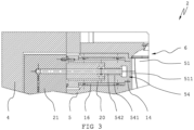
- the figure 3 shows a vertical sectional view through one of the areas 511 from FIG figure 2 . From this sectional view it can be seen that the area 511 is formed as part of the inner wall 51 .
- the region 511 has an associated section which is designed as a molded part 20 which is designed separately from the molded body 5 .
- the molded part 20 is embedded in the molded body 5 at its end facing the mold cavity 6 and is subsequently spaced apart from the molded body 5 in the direction of the base plate 4 by an insulating element 16 .
- the insulation element 16 is additionally spaced from the shaped body 5 by two O-rings.
- the tempering channels 54 are formed within the molded part 20 .
- a bore 541 is provided in molded part 20, into which a tube 542 opens or this bore 541 penetrates along its length, so that an annular gap is formed between tube 542 under the inner wall of bore 541, through which the temperature control medium is guided in the vicinity of region 511 can be, or can be discharged from this.
- the pipe 542 opens into a corresponding channel on the distributor block 521 and the annular gap correspondingly opens into another channel on the distributor block 21. These channels open into the connections 211 and 212 respectively (see figure 2 ).
- the cooling channel 54 has an extension at its end lying adjacent to the region 511, so that the cooling channel 54 forms a chamber.
- This chamber connects the annular gap and the Tube so that a cooling circuit can be provided.
- the chamber is spaced apart from the mold cavity 6 with a wall thickness which is 3 mm in the present case. This ensures that the heat that this wall thickness has, for example after blow molding, can be dissipated quickly, or that the wall thickness can be heated up quickly with a suitable heating medium so that its temperature essentially corresponds to that of the preform that is placed in the mold cavity 6 is introduced for blow molding.
- first area 511 of mold cavity 6 of molded body 5 of a first blow mold half 2 of blow molding tool 1 is heated by supplying a temperature control medium through separate temperature control channels 54 heated up.
- the preform is then introduced into the mold cavity 6 .
- the blow molding tool 1 is then closed and the plastic container is formed by inflating the preform and placing the preform against the inner wall 51 of the mold cavity 6 .
- the area is cooled by supplying a cooling medium through the temperature control channels 54 and the plastic container is removed from the mold when a specific cooling temperature is reached.
Landscapes
- Engineering & Computer Science (AREA)
- Manufacturing & Machinery (AREA)
- Mechanical Engineering (AREA)
- Physics & Mathematics (AREA)
- Thermal Sciences (AREA)
- Moulds For Moulding Plastics Or The Like (AREA)
- Blow-Moulding Or Thermoforming Of Plastics Or The Like (AREA)
Description
- Die Erfindung betrifft ein Blasformwerkzeug für eine Blasformmaschine sowie ein Verfahren zur thermischen Behandlung eines Teilbereiches einer Oberfläche eines Kunststoffbehälters.
- Ein- oder mehrschichtige Kunststoffbehälter beispielsweise aus Polyolefinen werden oft in einem Extrusionsblasverfahren, insbesondere in einem Schlauchblasverfahren hergestellt. Dabei wird mit einem Extrusionskopf üblicherweise kontinuierlich ein Kunststoffschlauch extrudiert, der ein- oder mehrschichtig ausgebildet sein kann. Der Kunststoffschlauch wird abschnittsweise in eine Formkavität, auch bekannt als Formnest, eines Blasformwerkzeugs eingebracht, durch ein mit Überdruck eingebrachtes Blasmedium in die gewünschte Form gebracht, abgekühlt und entformt. Das Blasformwerkzeug besteht üblicherweise aus zwei Blasformhälften, in denen jeweils eine Hälfte der Formkavität ausgebildet ist. Die Blasformhälften werden periodisch geöffnet, geschlossen und wieder geöffnet, um einen Schlauchabschnitt in die Formkavität einzubringen und nach dem Aufblasen den fertigen Behälter wieder zu entformen.
- Ein weiteres, sehr häufig eingesetztes Herstellverfahren für Kunststoffbehälter stellt das Streckblasen dar. Bei diesem Verfahren wird ein sogenannter Preform, der meist eine längliche, röhrchenartige Gestalt besitzt, an seinem einen Längsende einen Boden und am anderen Längsende einen Halsbereich mit ausgeformten Befestigungselementen für eine Verschlusskappe, beispielsweise Gewindeabschnitte, in eine Formkavität eines Blasformwerkzeugs eingesetzt und durch ein mit Überdruck eingebrachtes Blasmedium in die gewünschte Form gebracht. Dabei wird der Preform zusätzlich mit einem durch die Halsöffnung eingefahrenen Reckdorn in axiale Richtung gereckt. Nach dem Streck-/Blasvorgang wird der fertige Kunststoffbehälter abgekühlt und aus dem Blasformwerkzeug entformt.
- Der ein- oder mehrschichtige Preform wird vor dem Streckblasprozess typischerweise in einem separaten Spritzgiessverfahren hergestellt. Es ist auch schon vorgeschlagen worden, Preforms in einem Kunststoffpressformverfahren oder durch einen Extrusionsblasprozess herzustellen. Als Rohstoff für die Herstellung von Kunststoffbehältern im Streckblasprozess kommen vor allem Polyethylenterephthalat (PET) und ähnliche Materialien, wie z.B. Polyethylenfuranoat (PEF) oder Polyolefine, wie z.B. Polypropylen (PP), High Density Polyethylen (HDPE) oder Low Density Polyethylen (LDPE) zum Einsatz. Im sogenannten Einstufen-Streckblasprozess wird der Preform unmittelbar nach seiner Herstellung in die Formkavität des Blasformwerkzeugs eingesetzt und zu einem Kunststoffbehälter aufgeblasen und gereckt. Vielfach werden die Kunststoffbehälter jedoch in einem zweistufigen Verfahren hergestellt. Dabei werden in einem ersten Schritt die Preforms hergestellt und für die spätere Verwendung zwischengelagert. Beim späteren Streckblasprozess werden die Preforms zunächst wieder erwärmt, in die Formkavität eines Blasformwerkzeugs eingebracht, mit einem Reckdorn in Längsrichtung gestreckt und üblicherweise durch Überdruck zu einem Kunststoffbehälter gemäss der Formkavität aufgeblasen. Auf diese Weise können beide Prozesse, das Spritzgiessen und das Streckblasen, separat und optimal betrieben werden.
- Auch beim Streckblasprozess wird üblicherweise ein Blasformwerkzeug eingesetzt, das aus zwei Blasformhälften besteht, in denen jeweils ein Teil der Formkavität ausgebildet ist. Ein zweiteiliges Blasformwerkzeug ist beispielsweise in der
EP 2 703 146 A1 offenbart. - Die Blasformhälften werden periodisch geöffnet, geschlossen und wieder geöffnet, um den Preform einzusetzen, aufzublasen und zu recken und den fertigen Kunststoffbehälter zu entformen.
- Der extrudierte Schlauch und auch der Preform werden in ihren jeweiligen Verfahren einheitlich als Vorformling bezeichnet.
- Damit der Vorformling beim Einsetzen in die Formkavität des Blasformwerkzeugs keinen Temperaturschock erleidet, der zu einem bereichsweisen Ausfrieren des Kunststoffmaterials führen und eine weitere optimale Verformung im Blasprozess behindern könnte, sollten die formgebenden Innenflächen, also insbesondere die Innenwandungen der Formnester, des Blasformwerkzeugs beim Einsetzen des Vorformlings, eine Temperatur aufweisen, die sich nicht wesentlich von der Temperatur des Schlauchs unterscheidet. Das heisst, die Temperatur der Innenflächen des Blasformwerkzeuges weichen im Zeitpunkt des Einsetzens des Vorformlings vorzugsweise nicht mehr als rund 10% von der Temperatur des Vorformlings ab. Polyolefine werden typischerweise bei einer Temperatur von 180° Celsius mit einer Abweichung von bis zu 20° K eingesetzt, Polyethylenterephthalat wird typischerweise bei Temperaturen von 240° Celsius bis 280° Celsius mit einer Abweichung von bis zu 20° K eingesetzt. Andererseits muss das Blasformwerkzeug am Ende des Blasprozesses, vor dem Entformen des hergestellten Kunststoffbehälters soweit herunter gekühlt sein, dass der Polymerisierungsvorgang des Kunststoffmaterials weitgehend abgeschlossen ist und es beim weiteren Behandeln des Kunststoffbehälters zu keinen unterwünschten Verformungen mehr kommen kann.
- Polyolefine werden typischerweise bei ca. 60° Celsius entformt wobei die Temperatur am Hals noch bei ca. 80° Celsius liegt und Polyethylenterephtalat bei ca. 30° Celsius, wobei der Hals- und Bodenbereich eine höhere Temperatur von rund 60° Celsius aufweisen kann. Damit entsteht eine entsprechend hohe Temperaturdifferenz während des Blasformvorgangs.
- Blasformwerkzeuge sind üblicherweise mehrteilig aufgebaut und bestehen meist aus Aluminium oder Stahl oder auch aus Buntmetallen. Die beiden Blasformhälften eines Blasformwerkzeugs weisen jeweils einen Formkörper auf, in dem wenigstens ein Formnest ausgebildet ist. Der Formkörper ist auf einer Grundplatte aus Stahl montiert, die Bestandteil der Schliesseinheit der Blasformmaschine ist. Wegen der beim Blasformprozess auftretenden Drücke müssen die Grundplatten und die Formkörper relativ massiv ausgebildet sein. Aus dem Spritzgiessverfahren sind Formwerkzeuge bekannt, die sehr ähnlich aufgebaut sind, jedoch eine deutlich massivere Ausgestaltung aufweisen, um den beim Spritzgiessen auftretenden Drücken, die um ein Vielfaches höher sind als bei Blasformverfahren, standzuhalten.
- Berücksichtigt man die relativ guten Wärmeleiteigenschaften der einzelnen Komponenten bei Blasformwerkzeugen, ist unmittelbar einsichtig, dass ein sehr grosser Aufwand für das periodische Aufheizen und Abkühlen der Blasformwerkzeuge getrieben werden muss, um einigermassen akzeptable Zykluszeiten zu erreichen und gleichzeitig qualitativ hochwertige Produkte herstellen zu können. Es ist bekannt, dass das Erwärmen bzw. Abkühlen des Blasformwerkzeugs mittels eines geeigneten Fluids, beispielsweise Wassers, das in Kanälen, Fräsungen und Bohrungen des Blasformwerkzeugs unter Druck zirkuliert wird, erfolgen kann. Zur Erzielung möglichst kurzer Zykluszeiten wird das Heiz-/Kühlfluid mit relativ hohem Druck durch die Kanäle, Fräsungen und Bohrungen geleitet. Damit das Blasformwerkzeug diesen hohen Drücken standhält, muss es umso massiver ausgebildet werden. In Verbindung mit den guten Wärmeleiteigenschaften der für das Blasformwerkzeug verwendeten Materialien ergibt sich daraus jedoch ein noch höherer Aufwand für das periodische Aufheizen und Abkühlen des Blasformwerkzeugs. Ausserdem erhöht sich durch die massivere Ausbildung des Blasformwerkzeugs auch der für das periodische Öffnen und Schliessen der Blasformhälften erforderliche Aufwand.
- Aufgrund der mangelnden Wirtschaftlichkeit wurde bis anhin darauf verzichtet, die Formen auf die vorliegend beschriebenen bevorzugten Temperaturen aufzuheizen. Der Aufwand, um die eingetragene Wärme wieder auszubringen ist enorm und bedingt eine sehr hohe Kühlleistung. Zudem verlängert dies die Zykluszeit, da bis zum Entformen gewartet werden muss, bis die gesamte Temperaturdifferenz abgebaut ist. Dabei wurde in Kauf genommen, dass die fertigen Oberflächen der produzierten Behälter aufgrund der zu grossen Temperaturdifferenz Mängel aufweisen können. Vielfach werden derartige Behälter mit einer aufgeschrumpften Umverpackung versehen, sodass diese Mängel verdeckt bleiben.
- Blasformen, die das durchgehende und gleichmässige Kühlen ermöglichen, wurden mit der
US 2010/0252963 A1 und derWO 00/27612 A1 - Es ist daher eine Aufgabe der Erfindung zumindest einen oder mehrere Nachteile des Standes der Technik zu beheben. Insbesondere soll ein Blasformwerkzeug und/oder ein Verfahren zur thermischen Behandlung eines Teilbereichs einer Oberfläche eines Kunststoffbehälters bereitgestellt werden mit dem es ermöglicht ist, Oberflächen und/oder Behälterteile während des Herstellungsprozesses mit einem bestimmten Temperaturprofil zu versehen. Vorzugsweise werden die Zykluszeiten gegenüber dem Stand der Technik nicht verlängert und die Produktionskosten tief gehalten.
- Diese Aufgabe wird durch die in den unabhängigen Patentansprüchen definierten Vorrichtungen und Verfahren gelöst. Weitere Ausführungsformen ergeben sich aus den abhängigen Patentansprüchen.
- Ein erfindungsgemässes Blasformwerkzeug für eine Blasformmaschine, insbesondere ein Extrusionsblasformwerkzeug, weist zumindest eine erste Blasformhälfte und eine zweite Blasformhälfte auf. Die erste Blasformhälfte weist eine Grundplatte und einen Formkörper auf. Im Formkörper ist wenigstens ein Formnest mit einer Innenwandung angeordnet. Zumindest ein Bereich der Innenwandung des Formnestes weist in seinem zugehörigen Abschnitt des Formkörpers separate Temperierkanäle zum Temperieren dieses Bereichs auf. Der Bereich der Innenwandung ist definitionsgemäss ebenfalls ein Teil der Innenwandung.
- Das Vorsehen von separaten Temperierkanälen ermöglicht das gezielte Temperieren, also das Aufwärmen oder Abkühlen, eines Teilbereichs des Formnestes, also des Bereiches der Innenwandung. Dies ermöglicht einerseits diesen Bereich unabhängig von dem restlichen Formkörper zu Temperieren. Andererseits ist durch die Ausbildung des Bereichs als ein separat temperierter Teilbereich dieser im Verhältnis zum Formnest kleiner und weist somit eine geringere Masse auf. Dies ermöglicht das sehr schnelle Aufheizen oder das sehr schnelle Abkühlen dieses Bereichs.
- Unter einem zugehörigen Abschnitt wird definitionsgemäss ein zur Innenwandung abgewandter Teilbereich des Formkörpers verstanden, der im Formkörper hinter dem Bereich angeordnet ist.
- Es versteht sich von selbst, dass auch mehrere Bereiche möglich sind die jeweils alle in ihrem zugehörigen Abschnitt des Formkörpers separate Temperierkanäle aufweisen.
- Dies ermöglicht das unabhängige Temperieren von mehreren Teilbereichen eines Formnestes. Dabei kann ein entsprechendes Temperaturprofil eines ersten Bereichs sowohl zeitlich als auch bezüglich der Temperatur unterschiedlich zum Temperaturprofil eines zweiten Teilbereichs gefahren werden.
- Alternativ ist es auch möglich, mehrere Bereiche vorzusehen, die jeweils in ihrem zugehörigen Abschnitt des Formkörpers separate Temperierkanäle aufweisen, wobei jedoch diese einen oder mehrere Bereiche einen gemeinsamen, jedoch vom restlichen Formkörper unabhängigen, Temperierkreislauf aufweisen.
- Dies stellt sicher, dass die mehreren Bereiche ein gemeinsames Temperaturprofil aufweisen.
- Wie bereits dargelegt ist die aufzuheizende bzw. wieder abzukühlende Masse deutlich reduziert und ist das Aufheizen bzw. Abkühlen im Wesentlichen nur noch auf den Bereich und seinen zugehörigen Abschnitt selbst reduziert. Dadurch ist ein sehr viel geringerer Energieaufwand für das Aufheizen bzw. das Abkühlen des Bereichs nötig. Wegen der geringeren Masse können das Aufheizen und das Abkühlen des Formkörpers in einer relativ kurzen Zeit bewerkstelligt werden. Insbesondere ist ein Aufheizen oder Abkühlen mit einer Geschwindigkeit von 5 K/s vorzugsweise 15 K/s und besonders bevorzugt 30 K/s oder mehr ermöglicht. Die beheizten und in unmittelbarer Folge wieder gekühlten Oberflächen der Formnester erlauben in Verbindung mit polierten formgebenden Oberflächen des Bereichs und den kurzen Abkühlungszeiten auch die Herstellung von Kunststoffbehältern mit glänzenden Oberflächen an den jeweiligen Stellen.
- Polierte Oberflächen sind Oberflächen, die beispielsweise mittels Polituren bearbeitet wurden und eine geringe Menge von Material abgetragen wurde, um eine entsprechende Oberfläche durch Abtragen von Rauheitsspitzen zu glätten und an dieser Oberfläche gegebenenfalls Glanz zu erzeugen. Von polierten Oberflächen wird typischerweise ab Mittenrauwerten von 0.8 µm gesprochen.
- Der Glanz von Oberflächen wird mittels Reflektometern in sogenannten "gloss units" (GU) ausgedrückt. Vorliegend wird von Glanz gesprochen, wenn der Glanz 10 GU's überschreitet. Die Messung wird nach ISO 2813 durchgeführt. Für ganz oder teilweise transparente Objekte wird kein Reflektometer verwendet, sondern der Reflexionsgrad also der Quotient aus reflektiertem zu eingestrahltem Licht, für einen bestimmten Winkel angegeben. Bei ganz oder teilweise transparenten Kunststoffen wird von Glanz gesprochen, wenn der Reflexionsgrad 20% übersteigt.
- Durch die erfindungsgemässe Ausbildung des Blasformwerkzeugs können sogar mit Kunststoffen, wie z.B. Polyolefinen, bei denen es bekanntermassen sonst ohne zusätzliche Arbeitsschritte, wie beispielsweise einem mehrschichtigen Aufbau des Behälters beziehungsweise des Vorformling, bei dem die äusserste Schicht, die einen Glanz hervorrufen soll, niedrigviskos ist und zum Erreichen der geringen Viskosität unterschiedliche Zuschlagstoffe enthält, nicht möglich ist, solche glänzenden Oberflächen erzielt werden. Bei entsprechender Ausgestaltung der Oberflächen des Bereichs können auch Kunststoffbehälter mit zumindest in Teilbereichen strukturierten Oberflächen hergestellt werden. Somit sind bei entsprechender Gestaltung der Oberflächen sogar Behälter herstellbar, die Oberflächen aufweisen, welche in Teilbereichen des Bereichs glänzend und in anderen Teilbereichen des Bereichs strukturiert ausgebildet sind.
- Strukturiert heisst vorliegend, dass die Oberfläche des Behälters im Wesentlichen dem Negativ des Formkörpers entspricht, wobei die Abweichung zwischen dem Negativ und der späteren Oberfläche 15% nicht überschreitet, vorzugsweise 10% nicht überschreitet und besonders bevorzugt 5% nicht überschreitet.
- Es versteht sich von selbst, dass bei Bezug auf das Formnest in einer Blasformhälfte lediglich der Teil des Formnestes gemeint ist, der sich auch in der jeweiligen Blasformhälfte befindet. Erst durch das Zusammenfügen der Blasformhälften (oder Teile, wenn das Blasformwerkzeug mehr als zweiteilig ist) ist das ganze Formnest zur Verfügung gestellt. Das Formnest entspricht im Wesentlichen dem Negativ des späteren Kunststoffbehälters.
- Es kann vorgesehen sein, dass der Bereich mit seinem zugehörigen Abschnitt an einem zum Formkörper gesondert ausgebildeten Formteil ausgebildet ist.
- Dies ermöglicht einerseits die separate Fertigung des zugehörigen Abschnitts und der darin enthaltenen Temperierkanäle, andererseits ist durch die separate Ausbildung eine von der Oberfläche der restlichen Innenwandung unterschiedlich gestaltete Ausbildung der Oberfläche des Bereichs ermöglicht.
- Ausserdem ist die Wartung des Blasformwerkzeugs erleichtert. Es ist zu erwarten, dass durch schnelle Wechsel von Temperaturprofilen der Bereich und der dazugehörige Abschnitt des Formwerkzeugs mehr belastet wird als das restliche Blasformwerkzeug und entsprechend dieser Bereich mit seinem zugehörigen Abschnitt früher Verschleiss zeigt. Durch die separate Ausbildung ist es ermöglicht, diesen verschlissenen Bereich durch Austausch des Formteils auszutauschen und das Blasformwerkzeug instand zustellen.
- Das Formteil kann aus Aluminium oder einer Legierung davon ausgebildet sein. Aluminium hat einen kleineren Wärmeausdehnungskoeffizienten im Vergleich zu Stahl. Dies führt dazu, dass ein, in einem Formkörper aus Stahl angeordneten, Formteil aus Aluminium Spannungen, hervorgerufen durch Wärmeausdehnung, im Vergleich zu einer Kombination Stahl-Stahl verringert werden.
- Es kann zudem vorgesehen sein, dass zwischen dem Formteil und dem Formkörper ein Isolationselement aus einem thermisch isolierenden Material angeordnet ist. Je nach Ausgestaltung des Formteils wird auch von einem Isolationsblock gesprochen.
- Die aufzuheizende bzw. abzukühlende Masse des Bereichs und seines zugehörigen Abschnitts ist somit vom restlichen Formkörper zumindest teilweise thermisch entkoppelt. Diese reduziert den Wärmeübergang vom Formteil auf den Formkörper und reduziert damit die Masse die abzukühlen, bzw. aufzuheizen ist. Diese reduziert einerseits den Energieaufwand und andererseits ermöglicht es, bei gleichem Energieaufwand den Bereich schneller abzukühlen bzw. aufzuheizen.
- Das Isolationselement kann aus einem duroplastischen, hochtemperaturbeständigen Kunststoff mit geringer Wärmeleitfähigkeit bestehen.
- Dies ermöglicht eine hohe Standdauer und verhindert ungewollte Wärmeströme.
- Diese Kunststoffe zeichnen sich durch ihre sehr geringe Wärmeleitfähigkeit aus, die je nach Art des Kunststoffs nur 0,1 - 0,8 W/mK beträgt. Für den Einsatz in Verbindung mit Blasformwerkzeugen gemäss der Erfindung sind insbesondere Kunststoffe aus der Gruppe bestehend aus Polyaryletherketonen, wie z.B. Polyetheretherketon (PEEK), Polyamiden, glasfaserverstärkten Kunststoffen und verstärkten Duroplasten mit einer Temperaturbeständigkeit bis mindestens 200°C bevorzugt. Es kann sich dabei insbesondere um einen harten Kunststoff oder ein hartes Kunststoffverbundmaterial handeln. Als harte Kunststoffe werden vorliegend Kunststoffe berücksichtigt, die eine Härte von mindestens 75 Shore aufweisen.
- Dies ermöglicht das passgenaue Fertigen und verhindert zudem, dass während des Betriebes durch hohe Drücke hervorgerufene Deformationen entstehen.
- Zur Versorgung der Temperierkanäle kann zwischen der Grundplatte und dem Formkörper ein Verteilerblock angeordnet sein.
- Ein Verteilerblock ermöglicht das gezielte Zuführen eines Temperiermediums, also eines Heiz- oder Kühlmediums, zu den Temperierkanälen. Ebenfalls kann durch einen Verteilerblock ein Austauschelement geschaffen werden, welches es ermöglicht, durch einfachen Austausch des Verteilerblocks mehrere Temperierkanäle miteinander, also gemeinsam, zu beaufschlagen oder aber alternativ auch einen oder mehrere Bereiche separat mit einem Temperiermedium zu beaufschlagen.
- Der Verteilerblock kann aus Aluminium oder einer Legierung davon ausgebildet sein. Die entsprechenden Vorteile einer derartigen Materialwahl sind im Bezug zum Formteil bereits erwähnt und treffen ebenfalls auf die Ausbildung des Verteilerblocks zu.
- Der Verteilerblock kann Anschlüsse für die Zu- und Abfuhr eines Heiz-/Kühlmediums, also eines Temperiermediums, zu den Temperierkanälen aufweisen.
- Durch die Anordnung der Anschlüsse am Verteilerblock können diese einfach gewartet werden. Die Herstellung ist ebenfalls vereinfacht da ein Verteilerblock typischerweise eine Erstreckung bis an die Aussenbereiche des Blasformwerkzeugs aufweist und die Anschlüsse entsprechend einfach zugänglich sind.
- Dabei kann vorgesehen sein, dass am Verteilerblock mehrere Anschlüsse zur Versorgung von mehreren Temperierkanälen angeordnet sind und diese jeweils separat ausgebildet sind. Dies ermöglicht das separate Beaufschlagen von unterschiedlichen Temperierkanälen. Durch den Austausch des Verteilerblocks ist es möglich, schnell und unkompliziert einen Verteilerblock einzufügen der lediglich einen einzelnen Satz Anschlüsse aufweist und der sämtliche vorhandenen Temperierkanäle miteinander verbindet, sodass diese gleichzeitig beaufschlagt werden können.
- Der Formkörper kann mehrteilig ausgebildet sein und einen Halseinsatz und/oder einen Bodenteil aufweisen. Entsprechend kann der Formkörper ein Mittelteil aufweisen.
- Dies erleichtert die Fertigung und ebenfalls die Wartung des Blasformwerkzeugs. So ist es beispielsweise möglich, den gesamten Halseinsatz und/oder den Bodenteil und/oder den Mittelteil als ein Bereich auszubilden der separate Temperierkanäle aufweist. Vorzugsweise ist jedoch zumindest in einem Bestandteil des Formkörpers, also beispielsweise im Halseinsatz und/oder ihm Bodenteil, vorzugsweise im Mittelteil, ein Bereich mit einem zugehörigen Abschnitt ausgebildet, der separate Temperierkanäle aufweist.
- Die Grundplatte kann aus rostfreiem Stahl ausgebildet sein. Die Ausbildung aus Stahl stellt sicher dass die Grundplatte die auftretenden Kräfte aufnehmen kann. Die Eigenschaft dass der Stahl rostfrei ist verhindert eine frühzeitige Korrosion der Grundplatte.
- Der Formkörper kann aus Aluminium oder einer Legierung davon ausgebildet sein.
- Da Aluminium einen relativ geringen Wärmeausdehnungskoeffizienten aufweist ist eine hohe Formtreue des Blasformwerkzeugs über einen breiten Temperaturbereich ermöglicht.
- Die Temperierkanäle können als eine Bohrung ausgebildet sein. Dabei ist vorzugsweise innerhalb der Bohrung ein konzentrisch angeordnetes Rohr angeordnet sodass sich zwischen dem Rohr und der Bohrung als Temperierkanal ein Ringsspalt ausbildet.
- Durch den Ringsspalt kann also beispielsweise das Temperiermedium in den zugehörigen Abschnitt des Bereichs eingebracht werden und durch das Rohr wieder ausgebracht werden, respektive durch das Rohr eingebracht und durch den Ringsspalt wieder ausgebracht werden. Die Fertigung der Temperierkanäle in dieser Art ist einfach, kostengünstig und schnell. Beim Versagen eines Rohres kann dieses einfach ausgetauscht werden.
- Eine Wandstärke zwischen dem Temperierkanal und dem Bereich beträgt mindestens 1.5 mm und höchstens 12 mm. Der Bereich ist Teil der Oberfläche der Innenwandung, mit anderen Worten, eine Materialstärke zwischen der geblasenen Form und dem Temperiermedium beträgt 1.5 mm bis 12 mm.
- Diese Dimensionierung garantiert einerseits eine Mindestfestigkeit hervorgerufen durch die Mindestwandstärke und andererseits einen Wärmeleitwiderstand der durch die maximale Abmessung dieser verbleibenden Wandstärke begrenzt ist. Entsprechend dynamisch kann der Bereich temperiert werden.
- Der Bereich kann eine strukturierte Oberfläche aufweisen. Dies ermöglicht eine entsprechende Abbildung der Struktur auf dem Behälter.
- Die zweite Blasformhälfte des Blasformwerkzeuges ist vorzugsweise entsprechend der ersten Blasformhälfte ausgebildet.
- Der Ausdruck Blasformhälfte ist nicht auf eine mathematische Teilung beschränkt. Bei asymmetrischen Kunststoffbehältern kann die Trennstelle versetzt sein, dennoch wird von Hälften gesprochen. Ebenso kann das Blasformwerkzeug mehrteilig, beispielsweise dreiteilig ausgebildet sein. Eine Blasformhälfte entspricht dann einem Teil der Blasformwerkzeuges, das durch eine erste und zweite Trennebene gegenüber weiteren Teilen des Blasformwerkzeuges abgegrenzt ist.
- Ein weiterer Aspekt der Erfindung betrifft eine Extrusionsblasformmaschine aufweisend ein Blasformwerkzeug wie vorliegend beschrieben.
- Die Extrusionsblasformmaschine kann gemeinsam mit dem Blasformwerkzeug konfiguriert werden, sodass die optimalen, also aufeinander abgestimmten, Prozessparameter erreicht werden und somit entsprechend kurze Zykluszeiten.
- Ein weiterer Aspekt der Erfindung betrifft ein Verfahren zur thermischen Behandlung eines Teilbereichs einer Oberfläche eines Kunststoffbehälters mit einem Blasformwerkzeug, insbesondere mit einem Blasformwerkzeug wie vorliegend beschrieben. Das Verfahren umfasst die Schritte:
- Aufheizen eines Bereichs eines Formnests eines Formkörpers einer ersten Blasformhälfte des Blasformwerkzeuges durch Zuführung eines Heizmediums durch separate Temperierkanäle,
- Einbringen eines Vorformlings in das Formnest,
- Schliessen des Blasformwerkzeugs
- Formen des Kunststoffbehälters durch Aufblasen des Vorformlings und durch Anlegen des Vorformlings an die Innenwandung des Formnestes
- Abkühlen des Bereichs durch Zuführung eines Kühlmediums durch die Temperierkanäle
- Entformen des Kunststoffbehälters.
- Das Heizmedium und das Kühlmedium können identisch sein jedoch weisen sie entsprechend ihres Zweckes unterschiedliche Temperaturen auf. Entsprechend wird allgemein von einem Temperiermedium gesprochen.
- Das vorliegende Verfahren ermöglicht das gezielte Temperieren eines Bereichs des aufgeblasenen Kunststoffbehälters wobei in diesem Bereich ein gegenüber dem restlichen Formnest unterschiedliches Temperaturprofil gefahren werden kann. Dies ermöglicht insbesondere das schnelle Aufheizen und das schnelle Abkühlen des entsprechenden Bereichs, sodass der entsprechende Bereich vor dem Einbringen des Vorformlings in das Formnest im Wesentlichen eine Temperatur aufweist, die der Temperatur des Vorformlings entspricht und diese Temperatur nach dem Aufblasen ohne wesentliche Verlängerung der Zykluszeit auf die Entformtemperatur gekühlt werden kann.
- Das schnelle Aufheizen und das schnelle Abkühlen auf die gewünschten Temperaturen ermöglicht das passgenaue Übertragen von Strukturen aus dem Formnest auf die Oberfläche des aufgeblasenen Kunststoffbehälters. Dabei kann es sich bei den Strukturen sowohl um strukturierte Oberflächen handeln als auch um polierte Oberflächen. Mit anderen Worten ermöglicht das vorliegende Verfahren das Übertragen einer Struktur von dem Formnest auf die Oberfläche des Behälters mit einer Abweichung von weniger als 15 %, vorzugsweise weniger als 10% und besonders bevorzugt weniger als 5% gegenüber der Negativstruktur.
- Durch das Temperieren lediglich eines Bereichs des Formnestes ist ein Verfahren geschaffen, das die Zykluszeit nur unwesentlich verlängert, da das restliche Formnest nicht zwingend auf die optimalen Temperaturen aufgeheizt werden muss und beispielsweise kontinuierlich gekühlt werden kann. Dies betrifft insbesondere Bereiche die später am Kunststoffbehälter nicht sichtbar sind und damit eine geringere Genauigkeit oder Oberflächenbeschaffenheit aufweisen können.
- Es kann dabei vorgesehen sein, dass der Bereich während des Formens des Kunststoffbehälters eine Temperatur aufweist, die gegenüber der verbleibenden Innenwandung des Formnestes erhöht ist. Entsprechend wird der Bereich des Kunststoffbehälters der auf dem Bereich zum Anliegen kommt mit einem anderen Temperaturprofil gefahren. Dies ermöglicht unterschiedliche Oberflächenbeschaffenheiten am Kunststoffbehälter hervorgerufen durch die Temperaturunterschiede.
- Vorzugsweise weist der Bereich beim Abkühlen eine mittlere Abkühlungsgeschwindigkeit von mindestens 5 K/s auf, bzw. wird mit einer Abkühlungsgeschwindigkeit von mindestens 5 K/s gekühlt, vorzugsweise 15 K/s und besonders bevorzugt 30 K/s.
- Dies begünstigt eine schnelle und damit passgenaue Erstarrung des Kunststoffbehälters in Bereichen die mit dem Bereich der Innenwandung des Formnestes in Kontakt sind.
- Vorzugsweise wird der Formkörper während des Abkühlens des Bereichs ebenfalls gekühlt.
- Dies verhindert ein Überhitzen des Blasformwerkzeugs.
- Vorzugsweise wird als Heizmedium und als Kühlmedium entsprechend temperiertes Wasser eingesetzt.
- Wasser verfügt über eine relativ hohe Wärmekapazität und ermöglicht das kostengünstige und dennoch schnelle Zuführen von Wärme oder Kälte in die Temperierkanäle des dem Bereich zugehörigen Abschnittes des Formkörpers.
- Vorzugsweise besteht der Vorformling im Wesentlichen aus einem Polyolefin. Das Heizmedium wird mit einer Temperatur von 120 °C bis 200 °C und vorzugsweise mit 160 °C zugeführt und das Kühlmedium wird mit einer Temperatur von 5 °C bis 40 °C, vorzugsweise 15 °C, zugeführt.
- Es hat sich gezeigt, dass diese Prozessparameter insbesondere auf das Bereitstellen des entsprechenden Temperiermediums einen positiven Einfluss haben, da diese Temperaturen relativ kostengünstig erreicht werden können.
- Anhand von schematischen Figuren ist nachfolgend exemplarisch ein Ausführungsbeispiel eines Blasformwerkzeuges näher erläutert. Es zeigt:
- Figur 1:
- ein Blasformwerkzeug aus dem Stand der Technik mit zwei Blasformhälften;
- Figur 2:
- eine erste Blasformhälfte;
- Figur 3:
- eine vertikale Schnittansicht durch die Blasform-hälfte der
Figur 2 . - Die
Figur 1 zeigt ein Blasformwerkzeug 1 aus dem Stand der Technik zur Erläuterung des prinzipiellen Aufbaus eines derartigen Werkzeugs. Das gesamthaft mit dem Bezugszeichen 1 versehene Blasformwerkzeug weist eine erste Blasformhälfte 2 und eine zweite Blasformhälfte 3 auf. Diese sind vorliegend relativ zueinander lateral verschiebbar, um das Blasformwerkzeug 1 periodisch zu öffnen und wieder zu schliessen. Jede Blasformhälfte 2, 3 umfasst eine Grundplatte 4, die einen Teil einer Schliesseinheit einer Blasformmaschine bildet. Auf der Grundplatte 4 ist ein Formkörper 5 montiert, in dem ein oder mehrere Formnester 6 ausgebildet sind. Gemäss dem dargestellten Ausführungsbeispiel weist der Formkörper 5 zwei Formnester 6 auf, die je eine Hälfte der Form eines Körpers eines Kunststoffbehälters festlegen. Da sich die Formnester entsprechen sind zur besseren Übersichtlichkeit nicht beide Formnester mit allen Bezugszeichen versehen obschon die Ausführungen jeweils für beide Formnester gelten. - Eine Kopfplatte 7 ist mit einer Kavität 8 zur Festlegung eines Halsabschnitts des Kunststoffbehälters ausgestattet. Im Fall eines Blasformwerkzeugs für eine Extrusionsblasformmaschine kann an der Kopfplatte 7 auch noch ein Halsmesser 9 für das Abtrennen eines in das Blasformwerkzeug 1 eingesetzten extrudierten Kunststoffschlauchs vorgesehen sein. Ein Bodenteil 10 schliesst die Formnester 6 am anderen Ende des Blasformwerkzeugs 1 ab. An den einander zugewandten Oberflächen 11, 12 der Blasformhälften 2, 3, welche eine Trennebene des Blasformwerkzeugs 1 festlegen, können Entlüftungsschlitze 13 ausgebildet sein. An einer der Blasformhälften 3 sind Führungsbolzen 14 ausgebildet, die beim Schliessen der Blasformhälften 2, 3 in Führungsbuchsen 15 der anderen Blasformhälfte 2 gleiten. Der Formkörper 5 weist eine Wandungsfläche, also eine Innenwandung 51 auf, die einen Teil des Formnestes 6 bildet.
- Die
Figur 2 zeigt eine erste Blasformhälfte 2 eines erfindungsgemässen Blasformwerkzeuges. Die Blasformhälfte 2 weist eine Grundplatte 4 auf. Auf der Grundplatte 4 angeordnet ist ein Verteilerblock 21 mit zwei Anschlüssen 211 und 212 zum Zuführen eines Temperiermediums. Auf dem Grundkörper 4 angeordnet ist ein Formkörper 5 sowie eine Bodenteil 10 welches an den Formkörper 5 anschliesst. Im Formkörper 5 eingelassen ist eine Kopfplatte 7. - Die Gesamtheit aus Formkörper 5, Bodenteil 10 und Kopfplatte 7 stellt ein Formnest 6 bereit. Als Teil des Formnestes 6 weist der Formkörper 5 eine Innenwandung 51 auf. Die Innenwandung 51 weist zwei Bereiche 511 auf wobei jedem Bereich 511 ein zugehöriger Abschnitt mit separaten Temperierkanälen 54 (siehe dazu
Figur 3 ) zugeordnet ist. Die Temperierkanäle 54 sind über den Verteilerblock 21 mit den Anschlüssen 211 und 212 verbunden. - Die
Figur 3 zeigt eine vertikale Schnittansicht durch einen der Bereiche 511 aus derFigur 2 . Aus dieser Schnittansicht ist ersichtlich, dass der Bereich 511 als Teil der Innenwandung 51 ausgebildet ist. Der Bereich 511 weist einen zugehörigen Abschnitt auf der als zum Formkörper 5 gesondert ausgebildetes Formteil 20 ausgebildet ist. Das Formteil 20 ist an seinem dem Formnest 6 zugewandten Ende in den Formkörper 5 eingebettet und nachfolgend, in Richtung der Grundplatte 4, mit einem Isolationselement 16 zu dem Formkörper 5 beabstandet. Zur besseren Isolation ist das Isolationselement 16 zusätzlich mit zwei O-Ringen vom Formkörper 5 beabstandet. - Innerhalb des Formteils 20 sind die Temperierkanäle 54 ausgebildet. Dazu ist im Formteil 20 eine Bohrung 541 vorgesehen in die ein Rohr 542 mündet bzw. diese Bohrung 541 ihrer Länge nach durchdringt, sodass zwischen dem Rohr 542 unter Innenwandung der Bohrung 541 ein ringförmiger Spalt entsteht durch welche das Temperiermedium in die Nähe des Bereichs 511 geführt werden kann, bzw. aus diesem abgeführt werden kann. Das Rohr 542 mündet in einen entsprechenden Kanal am Verteilerblock 521 und entsprechend mündet der ringförmige Spalt in einen weiteren Kanal am Verteilerblock 21. Diese Kanäle münden entsprechend in den Anschlüssen 211 und 212 (siehe
Figur 2 ). - Der Kühlkanal 54 weist an seinem benachbart zum Bereich 511 liegenden Ende eine Erweiterung auf, sodass der Kühlkanal 54 eine Kammer bildet. Diese Kammer verbindet den Ringspalt und das Rohr, sodass ein Kühlkreislauf bereitgestellt werden kann. Die Kammer ist mit einer Wandstärke zum Formnest 6 beabstandet die im vorliegenden Fall 3 mm beträgt. Dies stellt sicher, dass die Wärme die diese Wandstärke beispielsweise nach dem Blasformen aufweist, schnell abgeführt werden kann, bzw., dass die Wandstärke mit einem geeigneten Heizmedium schnell aufgewärmt werden kann, sodass ihre Temperatur im Wesentlichen jener des Vorformlings entspricht, der in das Formnest 6 zum Blasformen eingeführt wird.
- Bei dem Verfahren zur Herstellung eines Kunststoffbehälters und zur thermischen Behandlung eines Teilbereiches eines Kunststoffbehälters, welches übergreifend über alle Figuren beschrieben ist, wird zuerst der Bereich 511 des Formnests 6 des Formkörpers 5 einer ersten Blasformhälfte 2 des Blasformwerkzeuges 1 durch Zuführung eines Temperiermediums durch separate Temperierkanäle 54 aufgeheizt. Anschliessend wird der Vorformling in das Formnest 6 eingebracht. Nachfolgend wir das Blasformwerkzeug 1 geschlossen und der Kunststoffbehälters durch Aufblasen des Vorformlings und durch Anlegen des Vorformlings an die Innenwandung 51 des Formnestes 6 geformt. Nach dem Formen wird der Bereich durch Zuführung eines Kühlmediums durch die Temperierkanäle 54 gekühlt und beim Erreichen einer bestimmten Kühltemperatur der Kunststoffbehälter entformt.
Claims (21)
- Blasformwerkzeug (1) für eine Blasformmaschine (1), insbesondere ein Extrusionsblasformwerkzeug, aufweisendzumindest eine erste Blasformhälfte (2) und eine zweite Blasformhälfte (3),wobei die erste Blasformhälfte (2) eine Grundplatte (4) und einen Formkörper (5) aufweist,wobei im Formkörper (5) wenigstens ein Formnest (6) mit einer Innenwandung (51) angeordnet ist,dadurch gekennzeichnet, dasszumindest ein Bereich (511) der Innenwandung (51) des Formnestes (6) in seinem zugehörigen Abschnitt des Formkörpers (5) separate Temperierkanäle (54) zum Temperieren des Bereichs (54) aufweist.
- Blasformwerkzeug (1) nach Anspruch 1,
dadurch gekennzeichnet, dass
der Bereich (511) mit seinem zugehörigen Abschnitt an einem zum Formkörper (5) gesondert ausgebildeten Formteil (20) ausgebildet ist. - Blasformwerkzeug (1) nach Anspruch 2,
dadurch gekennzeichnet, dass
das Formteil (20) aus Aluminium oder einer Legierung davon ausgebildet ist. - Blasformwerkzeug (1) nach Anspruch 2 oder 3,
dadurch gekennzeichnet, dass
zwischen dem Formteil (20) und dem Formkörper (5) ein Isolationselement (16) aus einem thermisch isolierenden Material angeordnet ist. - Blasformwerkzeug (1) nach einem der Ansprüche 1 bis 4,
dadurch gekennzeichnet, dass
das Isolationselement (16) aus einem duroplastischen, hochtemperaturbeständigen Kunststoff mit geringer Wärmeleitfähigkeit besteht. - Blasformwerkzeug (1) nach einem der Ansprüche 1 bis 5,
dadurch gekennzeichnet, dass
zwischen der Grundplatte (4) und dem Formkörper (5) ein Verteilerblock (21) zur Versorgung der Temperierkanäle (54) angeordnet ist. - Blasformwerkzeug (1) nach einem der Ansprüche 1 bis 6,
dadurch gekennzeichnet, dass
der Verteilerblock (21) aus Aluminium oder einer Legierung davon ausgebildet ist. - Blasformwerkzeug (1) nach einem der Ansprüche 6 oder 7,
dadurch gekennzeichnet, dass
der Verteilerblock (21) Anschlüsse für die Zu- und Abfuhr eines Heiz-/Kühlmediums zu den Temperierkanälen (54) aufweist. - Blasformwerkzeug (1) nach einem der Ansprüche 1 bis 8,
dadurch gekennzeichnet, dass
der Formkörper (5) mehrteilig ausgebildet ist und einen Halseinsatz (18) und/oder ein Bodenteil (10) aufweist. - Blasformwerkzeug (1) nach einem der Ansprüche 1 bis 9,
dadurch gekennzeichnet, dass
die Grundplatte (4) aus rostfreiem Stahl ausgebildet ist. - Blasformwerkzeug (1) nach einem der Ansprüche 1 bis 10,
dadurch gekennzeichnet, dass der Formkörper (5) aus Aluminium oder einer Legierung davon ausgebildet ist. - Blasformwerkzeug (1) nach einem der Ansprüche 1 bis 11,
dadurch gekennzeichnet, dass
die Temperierkanäle (54) als eine Bohrung (541) ausgebildet sind, wobei innerhalb der Bohrung (541) ein konzentrisch angeordnetes Rohr (542) angeordnet ist, sodass sich zwischen dem Rohr (541) und der Bohrung (542) als Temperierkanal (54) ein Ringspalt ausbildet. - Blasformwerkzeug (1) nach einem der Ansprüche 1 bis 12,
dadurch gekennzeichnet, dass
eine Wandstärke zwischen dem Temperierkanal (54) und dem Bereich (511) mindestens 1.5 mm und höchstens 12 mm beträgt. - Blasformwerkzeug (1) nach einem der Ansprüche 1 bis 13,
dadurch gekennzeichnet, dass
der Bereich (511) eine strukturierte Oberfläche aufweist. - Extrusionsblasformmaschine aufweisend ein Blasformwerkzeug (1) nach einem der Ansprüche 1 bis 14.
- Verfahren zur thermischen Behandlung eines Teilbereiches einer Oberfläche eines Kunststoffbehälters mit einem Blasformwerkzeug (1), insbesondere mit einem Blasformwerkzeug (1) gemäss einem der Ansprüche 1 bis 15, umfassend die Schritte- Aufheizen eines Bereichs (511) eines Formnests (13) eines Formkörpers (5) einer ersten Blasformhälfte (2) des Blasformwerkzeuges (1) durch Zuführung eines Heizmediums durch separate Temperierkanäle (54),- Einbringen eines Vorformlings in das Formnest (6),- Schliessen des Blasformwerkzeugs (1)- Formen des Kunststoffbehälters durch Aufblasen des Vorformlings und durch Anlegen des Vorformlings an die Innenwandung des Formnestes (6)- Abkühlen des Bereichs (511) durch Zuführung eines Kühlmediums durch die Temperierkanäle (54)- Entformen des Kunststoffbehälters.
- Verfahren nach Anspruch 16,
dadurch gekennzeichnet, dass
der Bereich (511) während des Formens des Kunststoffbehälters eine Temperatur aufweist, die gegenüber einer Temperatur der verblebenden Innenwandung des Formnestes (6) erhöht ist. - Verfahren nach Anspruch 16 oder 17,
dadurch gekennzeichnet, dass
der Bereich (511) beim Abkühlen mit einer mittleren Abkühlungsgeschwindigkeit von mindestens 5 K/s, vorzugsweise 15K/s, besonders bevorzugt 30K/s gekühlt wird. - Verfahren nach einem der Ansprüche 16 bis 18,
dadurch gekennzeichnet, dass
der Formkörper (5) während des Abkühlens des Bereiches (511) ebenfalls gekühlt wird. - Verfahren nach einem der Ansprüche 16 bis 19,
dadurch gekennzeichnet, dass
als Heizmedium und als Kühlmedium entsprechend temperiertes Wasser eingesetzt wird. - Verfahren nach einem der Ansprüche 16 bis 20,
dadurch gekennzeichnet, dass
der Vorformling im Wesentlichen aus einem Polyolefin besteht, und dass das Heizmedium mit einer Temperatur von 120° C bis 200° C, vorzugsweise 160° C, und das Kühlmedium mit einer Temperatur von 5° C bis 40° C, vorzugsweise 15° C, zugeführt wird.
Applications Claiming Priority (2)
| Application Number | Priority Date | Filing Date | Title |
|---|---|---|---|
| CH00413/19A CH716011A1 (de) | 2019-03-29 | 2019-03-29 | Blasformwerkzeug für eine Blasformmaschine. |
| PCT/EP2020/058665 WO2020201062A1 (de) | 2019-03-29 | 2020-03-27 | Blasformwerkzeug und verfahren zur thermischen behandlung eines teilbereiches einer oberfläche eines kunststoffbehälters |
Publications (3)
| Publication Number | Publication Date |
|---|---|
| EP3946889A1 EP3946889A1 (de) | 2022-02-09 |
| EP3946889B1 true EP3946889B1 (de) | 2023-06-07 |
| EP3946889C0 EP3946889C0 (de) | 2023-06-07 |
Family
ID=66091823
Family Applications (3)
| Application Number | Title | Priority Date | Filing Date |
|---|---|---|---|
| EP20715051.7A Active EP3946888B1 (de) | 2019-03-29 | 2020-03-27 | Blasformwerkzeug für eine blasformmaschine |
| EP20715052.5A Active EP3946889B1 (de) | 2019-03-29 | 2020-03-27 | Blasformwerkzeug und verfahren zur thermischen behandlung eines teilbereiches einer oberfläche eines kunststoffbehälters |
| EP20715338.8A Active EP3946890B1 (de) | 2019-03-29 | 2020-03-27 | Verfahren zum übertragen einer negativstruktur einer oberfläche einer innenwandung eines blasformwerkzeuges und kunststoffbehälter |
Family Applications Before (1)
| Application Number | Title | Priority Date | Filing Date |
|---|---|---|---|
| EP20715051.7A Active EP3946888B1 (de) | 2019-03-29 | 2020-03-27 | Blasformwerkzeug für eine blasformmaschine |
Family Applications After (1)
| Application Number | Title | Priority Date | Filing Date |
|---|---|---|---|
| EP20715338.8A Active EP3946890B1 (de) | 2019-03-29 | 2020-03-27 | Verfahren zum übertragen einer negativstruktur einer oberfläche einer innenwandung eines blasformwerkzeuges und kunststoffbehälter |
Country Status (8)
| Country | Link |
|---|---|
| US (3) | US12030234B2 (de) |
| EP (3) | EP3946888B1 (de) |
| CN (3) | CN113631349B (de) |
| CH (1) | CH716011A1 (de) |
| MX (3) | MX2021011525A (de) |
| PL (2) | PL3946889T3 (de) |
| WO (3) | WO2020201061A1 (de) |
| ZA (3) | ZA202106100B (de) |
Families Citing this family (7)
| Publication number | Priority date | Publication date | Assignee | Title |
|---|---|---|---|---|
| CH716011A1 (de) * | 2019-03-29 | 2020-09-30 | Alpla Werke Alwin Lehner Gmbh & Co Kg | Blasformwerkzeug für eine Blasformmaschine. |
| FR3100474B1 (fr) * | 2019-09-11 | 2022-12-16 | Sidel Participations | Procédé de fabrication d’un récipient en matière plastique, comprenant un refroidissement non réfrigéré d’un fond de moule |
| CH717886A1 (de) | 2020-09-21 | 2022-03-31 | Alpla Werke Alwin Lehner Gmbh & Co Kg | Kunststoffbehälter und Verfahren zum Bestimmen einer Eigenschaft eines Kunststoffbehälters. |
| CH718218A1 (de) * | 2020-12-28 | 2022-06-30 | Alpla Werke Alwin Lehner Gmbh & Co Kg | Formkörper für ein Blasformwerkzeug und Blasformwerkzeug. |
| DE102023001403B3 (de) | 2023-04-11 | 2023-12-14 | Kocher-Plastik Maschinenbau Gmbh | Vorrichtung nebst zugehöriger Formwerkzeuge und System bestehend aus einem Satz von Formwerkzeugen |
| US20240359391A1 (en) * | 2023-04-27 | 2024-10-31 | Plastipak Packaging, Inc. | Mold insert, mold assembly, and system |
| CN116714224B (zh) * | 2023-08-08 | 2023-10-24 | 青州市鲁冠塑料有限公司 | 一种塑料吹塑成型设备 |
Family Cites Families (26)
| Publication number | Priority date | Publication date | Assignee | Title |
|---|---|---|---|---|
| DE2339019A1 (de) | 1973-08-01 | 1975-02-13 | 4 P Verpackungen Gmbh | Verfahren und vorrichtung zur herstellung von hohlkoerpern durch aufblasen von vorformlingen |
| US4206171A (en) | 1976-12-06 | 1980-06-03 | Owens-Illinois, Inc. | Method for thermal conditioning a thermoplastic parison |
| DE3301337A1 (de) * | 1983-01-17 | 1984-07-19 | Holger 5609 Hückeswagen Buchner | Verfahren zur herstellung einer kuehleinrichtung an werkzeugen zur formgebung von kunststoffen und das mit einer solchen kuehleinrichtung ausgestattete werkzeug |
| US5041247A (en) | 1988-09-29 | 1991-08-20 | General Electric Company | Method and apparatus for blow molding parts with smooth surfaces |
| GB2239626A (en) | 1990-01-09 | 1991-07-10 | William Douglas Lamb | A method of making a mould provided with cooling means |
| JPH0740426A (ja) * | 1993-07-28 | 1995-02-10 | Toppan Printing Co Ltd | ホログラムを有する中空容器及びその製造方法 |
| JP2795144B2 (ja) * | 1993-10-07 | 1998-09-10 | ジェイエスアール株式会社 | 成形用金型 |
| JP3414473B2 (ja) * | 1994-02-02 | 2003-06-09 | 旭化成株式会社 | 樹脂成形用金型 |
| CA2191093C (en) | 1995-03-27 | 2000-08-22 | Kurt H. Ruppman, Sr. | Method of making a molded plastic container |
| EP1048436A4 (de) | 1997-12-26 | 2002-03-06 | Nippon Steel Chemical Co | Blasformgerät und verfahren zum formen |
| WO2000027612A1 (fr) | 1998-11-10 | 2000-05-18 | Clair Costanzo | Moule et procede de moulage d'objets tubulaires compressibles axialement en matiere plastique semi-rigide, et produits obtenus par ce procede |
| WO2005123357A2 (en) * | 2004-06-10 | 2005-12-29 | Advanced Plastics Technologies Luxembourg S.A. | Methods and systems for cooling molds |
| EP1761376B1 (de) | 2004-06-28 | 2010-01-13 | Alpla-Werke Alwin Lehner GmbH und Co.KG | Herstellverfahren und extrusionsblasmaschine für kunststoffbehälter |
| FR2939073B1 (fr) | 2008-12-03 | 2010-12-31 | Sidel Participations | Formage des recipients avec contre-pression localisee |
| DE102009005142A1 (de) * | 2009-01-15 | 2010-07-22 | Krones Ag | Streckblasmaschine mit beheizbarer Blasform |
| US8808610B2 (en) * | 2009-04-01 | 2014-08-19 | Patrick E. Scharf | Systems and methods for cooling moving molds |
| DE102010020090B4 (de) | 2010-05-10 | 2013-07-18 | Kautex Maschinenbau Gmbh | Werkzeug zur Formung von Artikeln aus thermoplastischem Kunststoff |
| CN103492147A (zh) | 2011-02-21 | 2014-01-01 | 圣杯发明(私人)有限公司 | 模具组件 |
| FR2982789B1 (fr) * | 2011-11-22 | 2014-08-01 | Sidel Participations | Dispositif d'isolation thermique pour moule, moule equipe d'un tel dispositif et installation comprenant au moins un tel moule. |
| FR2994880B1 (fr) * | 2012-08-28 | 2014-08-29 | Sidel Participations | "procede de refroidissement d'un moule par circulation d'un fluide caloporteur au contact de sa face externe" |
| DE102013113335A1 (de) | 2013-12-02 | 2015-06-03 | Krones Ag | Blasformmaschine mit erwärmbarer Kühlmittelzuführung |
| EP3268206B1 (de) | 2015-03-09 | 2020-11-25 | Graham Packaging Company, L.P. | Verfahren, anordnungen, systeme und mehrkammerbehälter mit vormontagezwischenstufe zur herstellung eines mehrkammerbehälters |
| WO2016206080A1 (en) | 2015-06-26 | 2016-12-29 | The Procter & Gamble Company | Glossy container |
| FR3038541B1 (fr) * | 2015-07-08 | 2017-07-21 | Sidel Participations | Dispositif de moulage pour une machine de fabrication de recipients en matiere thermoplastique |
| FR3053906B1 (fr) * | 2016-12-12 | 2018-08-17 | Sidel Participations | Dispositif de moulage pour la mise en œuvre de procedes de moulage a chaud et de moulage a froid |
| CH716011A1 (de) * | 2019-03-29 | 2020-09-30 | Alpla Werke Alwin Lehner Gmbh & Co Kg | Blasformwerkzeug für eine Blasformmaschine. |
-
2019
- 2019-03-29 CH CH00413/19A patent/CH716011A1/de not_active Application Discontinuation
-
2020
- 2020-03-27 CN CN202080025164.3A patent/CN113631349B/zh active Active
- 2020-03-27 MX MX2021011525A patent/MX2021011525A/es unknown
- 2020-03-27 PL PL20715052.5T patent/PL3946889T3/pl unknown
- 2020-03-27 WO PCT/EP2020/058664 patent/WO2020201061A1/de not_active Ceased
- 2020-03-27 EP EP20715051.7A patent/EP3946888B1/de active Active
- 2020-03-27 CN CN202080025162.4A patent/CN113631348A/zh active Pending
- 2020-03-27 MX MX2021011518A patent/MX2021011518A/es unknown
- 2020-03-27 PL PL20715051.7T patent/PL3946888T3/pl unknown
- 2020-03-27 WO PCT/EP2020/058666 patent/WO2020201063A1/de not_active Ceased
- 2020-03-27 US US17/599,774 patent/US12030234B2/en active Active
- 2020-03-27 MX MX2021011526A patent/MX2021011526A/es unknown
- 2020-03-27 US US17/599,760 patent/US12064915B2/en active Active
- 2020-03-27 US US17/599,769 patent/US11975474B2/en active Active
- 2020-03-27 CN CN202080025161.XA patent/CN113661045B/zh active Active
- 2020-03-27 WO PCT/EP2020/058665 patent/WO2020201062A1/de not_active Ceased
- 2020-03-27 EP EP20715052.5A patent/EP3946889B1/de active Active
- 2020-03-27 EP EP20715338.8A patent/EP3946890B1/de active Active
-
2021
- 2021-08-24 ZA ZA2021/06100A patent/ZA202106100B/en unknown
- 2021-08-24 ZA ZA2021/06099A patent/ZA202106099B/en unknown
- 2021-08-24 ZA ZA2021/06098A patent/ZA202106098B/en unknown
Also Published As
Similar Documents
| Publication | Publication Date | Title |
|---|---|---|
| EP3946889B1 (de) | Blasformwerkzeug und verfahren zur thermischen behandlung eines teilbereiches einer oberfläche eines kunststoffbehälters | |
| DE69328561T2 (de) | Blasformling, verfahren und vorrichtung | |
| EP3055120B1 (de) | Verfahren und vorrichtung zum herstellen eines mit füllgut gefüllten behälters | |
| EP1299223A1 (de) | Vorrichtung zur blasformung von behältern | |
| DE102012004613A1 (de) | Verfahren und Vorrichtung zur Herstellung einer optimierten Bodenkontur von Preformen | |
| EP2113368B1 (de) | Vorrichtung zum Blasformen | |
| EP2332715A2 (de) | Blasformmaschine mit Kühleinrichtung | |
| DE102006032140A1 (de) | Verfahren und Vorrichtung zur Blasformung von Behältern | |
| EP1660301B2 (de) | Verfahren und vorrichtung zur blasformung von behältern | |
| WO2005023520A1 (de) | Verfahren und vorrichtung zur blasformung von behältern | |
| WO2010060919A2 (de) | Vorrichtung und verfahren zum herstellen von kunststoffbehältnissen und nach diesem verfahren hergestelltes kunststoffbehältnis | |
| EP3197655B1 (de) | Verfahren und vorrichtung zur herstellung einer optimierten halskontur an preformen | |
| EP3590695B1 (de) | Vulkanisationseinheit mit mindestens einem formträger sowie verwendung und verfahren zum vulkanisieren eines fahrzeugreifens | |
| EP1732743B1 (de) | Verfahren und vorrichtung zur blasformung von behältern unter verwendung einer reduzierten druckanstiegsgeschwindigkeit | |
| DE102004018146A1 (de) | Verfahren und Vorrichtung zur Blasformung von Behältern | |
| EP1960180A1 (de) | Nachbehandlungsverfahren sowie vorrichtung hierfür | |
| DE1704292A1 (de) | Verfahren zum Ausformen von Gegenstaenden aus thermoplastischen Kunststoffen | |
| EP2129508B1 (de) | Verfahren zur blasformung von behältern | |
| EP4267369B1 (de) | Formkörper für ein blasformwerkzeug und blasformwerkzeug | |
| WO2024251849A1 (de) | Extrusionsblasformmaschine und verfahren zum herstellen eines hohlkörpers | |
| DE102005032403A1 (de) | Verfahren und Vorrichtung zur Blasformung von Behältern | |
| DE3827772A1 (de) | Vorrichtung und verfahren zur formgebung von halbzeug aus hochmolekularen kunststoffen | |
| DE4107011A1 (de) | Verfahren und vorrichtung zum herstellen blasgeformter hohlkoerper | |
| DE102009056556A1 (de) | Blasform mit Neckkühlung | |
| DE10026368A1 (de) | Verfahren und Vorrichtung zur Herstellung von Vorformlingen |
Legal Events
| Date | Code | Title | Description |
|---|---|---|---|
| STAA | Information on the status of an ep patent application or granted ep patent |
Free format text: STATUS: UNKNOWN |
|
| STAA | Information on the status of an ep patent application or granted ep patent |
Free format text: STATUS: THE INTERNATIONAL PUBLICATION HAS BEEN MADE |
|
| PUAI | Public reference made under article 153(3) epc to a published international application that has entered the european phase |
Free format text: ORIGINAL CODE: 0009012 |
|
| STAA | Information on the status of an ep patent application or granted ep patent |
Free format text: STATUS: REQUEST FOR EXAMINATION WAS MADE |
|
| 17P | Request for examination filed |
Effective date: 20211020 |
|
| AK | Designated contracting states |
Kind code of ref document: A1 Designated state(s): AL AT BE BG CH CY CZ DE DK EE ES FI FR GB GR HR HU IE IS IT LI LT LU LV MC MK MT NL NO PL PT RO RS SE SI SK SM TR |
|
| DAV | Request for validation of the european patent (deleted) | ||
| DAX | Request for extension of the european patent (deleted) | ||
| GRAP | Despatch of communication of intention to grant a patent |
Free format text: ORIGINAL CODE: EPIDOSNIGR1 |
|
| STAA | Information on the status of an ep patent application or granted ep patent |
Free format text: STATUS: GRANT OF PATENT IS INTENDED |
|
| RIC1 | Information provided on ipc code assigned before grant |
Ipc: B29K 23/00 20060101ALN20220929BHEP Ipc: B29L 31/00 20060101ALN20220929BHEP Ipc: B29K 67/00 20060101ALN20220929BHEP Ipc: B29C 49/06 20060101ALN20220929BHEP Ipc: B29C 49/48 20060101AFI20220929BHEP |
|
| INTG | Intention to grant announced |
Effective date: 20221021 |
|
| GRAJ | Information related to disapproval of communication of intention to grant by the applicant or resumption of examination proceedings by the epo deleted |
Free format text: ORIGINAL CODE: EPIDOSDIGR1 |
|
| STAA | Information on the status of an ep patent application or granted ep patent |
Free format text: STATUS: REQUEST FOR EXAMINATION WAS MADE |
|
| GRAP | Despatch of communication of intention to grant a patent |
Free format text: ORIGINAL CODE: EPIDOSNIGR1 |
|
| STAA | Information on the status of an ep patent application or granted ep patent |
Free format text: STATUS: GRANT OF PATENT IS INTENDED |
|
| INTC | Intention to grant announced (deleted) | ||
| RIC1 | Information provided on ipc code assigned before grant |
Ipc: B29K 23/00 20060101ALN20230210BHEP Ipc: B29L 31/00 20060101ALN20230210BHEP Ipc: B29K 67/00 20060101ALN20230210BHEP Ipc: B29C 49/06 20060101ALN20230210BHEP Ipc: B29C 49/48 20060101AFI20230210BHEP |
|
| INTG | Intention to grant announced |
Effective date: 20230302 |
|
| GRAS | Grant fee paid |
Free format text: ORIGINAL CODE: EPIDOSNIGR3 |
|
| GRAA | (expected) grant |
Free format text: ORIGINAL CODE: 0009210 |
|
| STAA | Information on the status of an ep patent application or granted ep patent |
Free format text: STATUS: THE PATENT HAS BEEN GRANTED |
|
| AK | Designated contracting states |
Kind code of ref document: B1 Designated state(s): AL AT BE BG CH CY CZ DE DK EE ES FI FR GB GR HR HU IE IS IT LI LT LU LV MC MK MT NL NO PL PT RO RS SE SI SK SM TR |
|
| REG | Reference to a national code |
Ref country code: GB Ref legal event code: FG4D Free format text: NOT ENGLISH |
|
| REG | Reference to a national code |
Ref country code: CH Ref legal event code: EP Ref country code: AT Ref legal event code: REF Ref document number: 1573733 Country of ref document: AT Kind code of ref document: T Effective date: 20230615 |
|
| REG | Reference to a national code |
Ref country code: DE Ref legal event code: R096 Ref document number: 502020003664 Country of ref document: DE |
|
| U01 | Request for unitary effect filed |
Effective date: 20230607 |
|
| U07 | Unitary effect registered |
Designated state(s): AT BE BG DE DK EE FI FR IT LT LU LV MT NL PT SE SI Effective date: 20230612 |
|
| REG | Reference to a national code |
Ref country code: LT Ref legal event code: MG9D |
|
| PG25 | Lapsed in a contracting state [announced via postgrant information from national office to epo] |
Ref country code: NO Free format text: LAPSE BECAUSE OF FAILURE TO SUBMIT A TRANSLATION OF THE DESCRIPTION OR TO PAY THE FEE WITHIN THE PRESCRIBED TIME-LIMIT Effective date: 20230907 |
|
| REG | Reference to a national code |
Ref country code: ES Ref legal event code: FG2A Ref document number: 2952514 Country of ref document: ES Kind code of ref document: T3 Effective date: 20231031 |
|
| PG25 | Lapsed in a contracting state [announced via postgrant information from national office to epo] |
Ref country code: RS Free format text: LAPSE BECAUSE OF FAILURE TO SUBMIT A TRANSLATION OF THE DESCRIPTION OR TO PAY THE FEE WITHIN THE PRESCRIBED TIME-LIMIT Effective date: 20230607 Ref country code: HR Free format text: LAPSE BECAUSE OF FAILURE TO SUBMIT A TRANSLATION OF THE DESCRIPTION OR TO PAY THE FEE WITHIN THE PRESCRIBED TIME-LIMIT Effective date: 20230607 Ref country code: GR Free format text: LAPSE BECAUSE OF FAILURE TO SUBMIT A TRANSLATION OF THE DESCRIPTION OR TO PAY THE FEE WITHIN THE PRESCRIBED TIME-LIMIT Effective date: 20230908 |
|
| PG25 | Lapsed in a contracting state [announced via postgrant information from national office to epo] |
Ref country code: SK Free format text: LAPSE BECAUSE OF FAILURE TO SUBMIT A TRANSLATION OF THE DESCRIPTION OR TO PAY THE FEE WITHIN THE PRESCRIBED TIME-LIMIT Effective date: 20230607 |
|
| PG25 | Lapsed in a contracting state [announced via postgrant information from national office to epo] |
Ref country code: IS Free format text: LAPSE BECAUSE OF FAILURE TO SUBMIT A TRANSLATION OF THE DESCRIPTION OR TO PAY THE FEE WITHIN THE PRESCRIBED TIME-LIMIT Effective date: 20231007 |
|
| PG25 | Lapsed in a contracting state [announced via postgrant information from national office to epo] |
Ref country code: SM Free format text: LAPSE BECAUSE OF FAILURE TO SUBMIT A TRANSLATION OF THE DESCRIPTION OR TO PAY THE FEE WITHIN THE PRESCRIBED TIME-LIMIT Effective date: 20230607 Ref country code: SK Free format text: LAPSE BECAUSE OF FAILURE TO SUBMIT A TRANSLATION OF THE DESCRIPTION OR TO PAY THE FEE WITHIN THE PRESCRIBED TIME-LIMIT Effective date: 20230607 Ref country code: RO Free format text: LAPSE BECAUSE OF FAILURE TO SUBMIT A TRANSLATION OF THE DESCRIPTION OR TO PAY THE FEE WITHIN THE PRESCRIBED TIME-LIMIT Effective date: 20230607 Ref country code: IS Free format text: LAPSE BECAUSE OF FAILURE TO SUBMIT A TRANSLATION OF THE DESCRIPTION OR TO PAY THE FEE WITHIN THE PRESCRIBED TIME-LIMIT Effective date: 20231007 Ref country code: CZ Free format text: LAPSE BECAUSE OF FAILURE TO SUBMIT A TRANSLATION OF THE DESCRIPTION OR TO PAY THE FEE WITHIN THE PRESCRIBED TIME-LIMIT Effective date: 20230607 |
|
| REG | Reference to a national code |
Ref country code: DE Ref legal event code: R097 Ref document number: 502020003664 Country of ref document: DE |
|
| PLBE | No opposition filed within time limit |
Free format text: ORIGINAL CODE: 0009261 |
|
| STAA | Information on the status of an ep patent application or granted ep patent |
Free format text: STATUS: NO OPPOSITION FILED WITHIN TIME LIMIT |
|
| U20 | Renewal fee for the european patent with unitary effect paid |
Year of fee payment: 5 Effective date: 20240325 |
|
| 26N | No opposition filed |
Effective date: 20240308 |
|
| PG25 | Lapsed in a contracting state [announced via postgrant information from national office to epo] |
Ref country code: MC Free format text: LAPSE BECAUSE OF FAILURE TO SUBMIT A TRANSLATION OF THE DESCRIPTION OR TO PAY THE FEE WITHIN THE PRESCRIBED TIME-LIMIT Effective date: 20230607 |
|
| PG25 | Lapsed in a contracting state [announced via postgrant information from national office to epo] |
Ref country code: MC Free format text: LAPSE BECAUSE OF FAILURE TO SUBMIT A TRANSLATION OF THE DESCRIPTION OR TO PAY THE FEE WITHIN THE PRESCRIBED TIME-LIMIT Effective date: 20230607 |
|
| PG25 | Lapsed in a contracting state [announced via postgrant information from national office to epo] |
Ref country code: IE Free format text: LAPSE BECAUSE OF NON-PAYMENT OF DUE FEES Effective date: 20240327 |
|
| PG25 | Lapsed in a contracting state [announced via postgrant information from national office to epo] |
Ref country code: IE Free format text: LAPSE BECAUSE OF NON-PAYMENT OF DUE FEES Effective date: 20240327 |
|
| PGFP | Annual fee paid to national office [announced via postgrant information from national office to epo] |
Ref country code: PL Payment date: 20250314 Year of fee payment: 6 |
|
| PGFP | Annual fee paid to national office [announced via postgrant information from national office to epo] |
Ref country code: GB Payment date: 20250324 Year of fee payment: 6 |
|
| U20 | Renewal fee for the european patent with unitary effect paid |
Year of fee payment: 6 Effective date: 20250325 |
|
| PGFP | Annual fee paid to national office [announced via postgrant information from national office to epo] |
Ref country code: ES Payment date: 20250416 Year of fee payment: 6 |
|
| PGFP | Annual fee paid to national office [announced via postgrant information from national office to epo] |
Ref country code: CH Payment date: 20250401 Year of fee payment: 6 |
|
| PG25 | Lapsed in a contracting state [announced via postgrant information from national office to epo] |
Ref country code: CY Free format text: LAPSE BECAUSE OF FAILURE TO SUBMIT A TRANSLATION OF THE DESCRIPTION OR TO PAY THE FEE WITHIN THE PRESCRIBED TIME-LIMIT; INVALID AB INITIO Effective date: 20200327 |
|
| PG25 | Lapsed in a contracting state [announced via postgrant information from national office to epo] |
Ref country code: HU Free format text: LAPSE BECAUSE OF FAILURE TO SUBMIT A TRANSLATION OF THE DESCRIPTION OR TO PAY THE FEE WITHIN THE PRESCRIBED TIME-LIMIT; INVALID AB INITIO Effective date: 20200327 |
|
| PG25 | Lapsed in a contracting state [announced via postgrant information from national office to epo] |
Ref country code: TR Free format text: LAPSE BECAUSE OF FAILURE TO SUBMIT A TRANSLATION OF THE DESCRIPTION OR TO PAY THE FEE WITHIN THE PRESCRIBED TIME-LIMIT Effective date: 20230607 |