EP3944827A1 - Instrument chirurgical à mécanique de verrouillage push-push - Google Patents
Instrument chirurgical à mécanique de verrouillage push-push Download PDFInfo
- Publication number
- EP3944827A1 EP3944827A1 EP20188396.4A EP20188396A EP3944827A1 EP 3944827 A1 EP3944827 A1 EP 3944827A1 EP 20188396 A EP20188396 A EP 20188396A EP 3944827 A1 EP3944827 A1 EP 3944827A1
- Authority
- EP
- European Patent Office
- Prior art keywords
- push
- surgical instrument
- latch
- handle
- locking mechanism
- Prior art date
- Legal status (The legal status is an assumption and is not a legal conclusion. Google has not performed a legal analysis and makes no representation as to the accuracy of the status listed.)
- Granted
Links
Images


Classifications
-
- A—HUMAN NECESSITIES
- A61—MEDICAL OR VETERINARY SCIENCE; HYGIENE
- A61B—DIAGNOSIS; SURGERY; IDENTIFICATION
- A61B17/00—Surgical instruments, devices or methods
- A61B17/28—Surgical forceps
- A61B17/29—Forceps for use in minimally invasive surgery
-
- A—HUMAN NECESSITIES
- A61—MEDICAL OR VETERINARY SCIENCE; HYGIENE
- A61B—DIAGNOSIS; SURGERY; IDENTIFICATION
- A61B17/00—Surgical instruments, devices or methods
- A61B17/28—Surgical forceps
- A61B17/29—Forceps for use in minimally invasive surgery
- A61B17/2909—Handles
-
- A—HUMAN NECESSITIES
- A61—MEDICAL OR VETERINARY SCIENCE; HYGIENE
- A61B—DIAGNOSIS; SURGERY; IDENTIFICATION
- A61B17/00—Surgical instruments, devices or methods
- A61B17/28—Surgical forceps
- A61B17/29—Forceps for use in minimally invasive surgery
- A61B2017/2946—Locking means
-
- A—HUMAN NECESSITIES
- A61—MEDICAL OR VETERINARY SCIENCE; HYGIENE
- A61B—DIAGNOSIS; SURGERY; IDENTIFICATION
- A61B17/00—Surgical instruments, devices or methods
- A61B17/30—Surgical pincettes, i.e. surgical tweezers without pivotal connections
- A61B2017/305—Tweezer like handles with tubular extensions, inner slidable actuating members and distal tools, e.g. microsurgical instruments
Definitions
- the invention relates to a surgical instrument with a push-push locking mechanism having the features of the preamble of claim 1.
- the push-push locking mechanism is used to releasably hold the surgical instrument in an actuated position.
- the surgical instrument is intended for use in minimally invasive surgery.
- the push-push locking mechanism is unlocked by a short movement in the same direction that led to the locking of the push-push locking mechanism. This direction can also be referred to as the locking direction.
- Push-push locking mechanisms are known, for example, from ballpoint pens and are sometimes also referred to as heart-shaped mechanisms due to the shape of a locking piece. Push-push locking mechanisms can have very different designs and geometries that don't necessarily look like a heart curve.
- the European patent application discloses such a surgical instrument with a push-push locking mechanism EP 2 792 319 A1 .
- This surgical instrument has a tubular hollow shank and a core that can be displaced in the hollow shank in order to actuate the instrument.
- Actuate means a pivoting and in particular a closing of, for example Jaws of pliers or blades of scissors by moving the core in the hollow shaft.
- the list is exemplary and not exhaustive.
- the jaws, blades or the like are arranged at an end of the hollow shaft remote from the handles of the surgical instrument.
- the known surgical instrument has two handles which are arranged symmetrically to the hollow shank in a V-shape at an acute angle to one another and which can be moved closer to one another to actuate the surgical instrument by pivoting about an apex of the V.
- the two handles of the known surgical instrument are designed as semi-cylindrical shells and have on their mutually facing hollow and inner sides a pair of rockers with a locking rocker and a locking rocker, which are pivotably mounted on the hollow and inner sides of the handles. Pivot axes of the two rockers run parallel to a pivot axis of the handles and perpendicular to a plane spanned by the two handles, which is also a plane of movement of the handles, in which the handles move. If the known surgical instrument is actuated by bringing its two handles closer together, the latching rocker engages with the locking rocker and holds the handles in the approached position and thereby the surgical instrument in an actuated position.
- the two rockers which come into engagement with one another by approaching and disengage from one another again by approaching again briefly, can also be understood as a push-push locking mechanism.
- the object of the invention is to propose a surgical instrument with an alternative push-push locking mechanism.
- the surgical instrument according to the invention is intended in particular for use in minimally invasive surgery. It has a handle and a counter-handle, which are used to actuate the surgical instrument are movable in relation to each other. In particular, the handle and the counter-handle can be approached and removed from one another. The invention does not rule out other possible movements of the handle in relation to the counter-handle.
- the handle and/or the counter-handle can be pivotable and/or displaceable. To actuate the surgical instrument, the handle is moved in relation to the counter-handle, in particular the handle is brought closer to the counter-handle to actuate the surgical instrument.
- the counter grip can also be a grip or, for example, a housing, base part, shaft or other part of the surgical instrument.
- the surgical instrument has forceps or scissors, the jaws or blades of which are brought closer together and preferably closed when actuated.
- the movement of the handle in relation to the counter-handle is transmitted, for example via a lever mechanism or a rack and pinion mechanism, to a core that can be moved in a hollow shaft or to two parallel shafts that can be moved in opposite directions, which pivot the jaws of the pliers or the blades of the scissors.
- the surgical instrument according to the invention has a push-push locking mechanism for releasably holding the surgical instrument in an actuated position.
- the push-push locking mechanism has a latch and a locking piece that engages behind the latch in a locked position.
- the surgical instrument In the locked position of the push-push locking mechanism, the surgical instrument is actuated and held in the actuated position by the push-push locking mechanism.
- the handle In order to release or unlock the push-push locking mechanism, the handle is again brought a short distance closer to the counter-handle or is generally moved in the locking direction, as a result of which the latch comes free from the locking piece and the push-push locking mechanism is unlocked.
- the surgical instrument can be moved back into a non-actuated initial position or moves back into the non-actuated initial position by itself, for example under the action of a spring.
- the designation of the parts of the push-push locking mechanism as latch and striker is based on a door lock.
- the catch of the push-push locking mechanism of the surgical instrument according to the invention can be deflected in two opposite directions. If the latch is deflected, it can step past the striker to lock and unlock. When locking, the latch engages with the striker and when unlocking, the latch disengages from the striker. When the latch is deflected, a restoring spring is tensioned independently of the direction of deflection and acts on the deflected latch against its deflection back into a non-deflected basic position.
- the latch When the handle is moved in relation to the counter-handle for actuating the surgical instrument, the latch is deflected, passes the closing piece and is moved by the return spring, which is tensioned when the latch is deflected, against the deflection into a locking position in which the latch comes into engagement with the locking piece, which can also be understood as reaching behind the locking piece of the latch.
- the push-push locking mechanism is locked and holds the surgical instrument in the actuated position.
- the handle is again moved a short distance in the actuation direction, the latch being deflected again and preferably in the opposite direction to that of the locking mechanism and being released from the locking piece or disengaged from the locking piece.
- the deflected latch passes the closing piece and the surgical instrument returns to a non-actuated basic position.
- the return spring moves the latch back to the non-deflected home position so that the surgical instrument can be actuated again, with the push-push locking mechanism again automatically locking the instrument in the actuated position.
- the latch is arranged on the handle and/or the striker on the counter-handle, or vice versa, so that when the handle and counter-handle are approached, the latch and striker move closer together until the latch engages behind the striker and prevents the handle and the counter-handle from being separated from each other.
- Engagement of the latch with the striker means that the push-push locking mechanism is locked, with the locked push-push locking mechanism holding the handle and counter-handle or surgical instrument in the actuated position.
- the handle and the counter-handle To release or unlock the push-push locking mechanism, the handle and the counter-handle must be moved closer together, which causes the latch to be disengaged from the locking piece again, so that the handle and the counter-handle can then be moved apart.
- one embodiment of the invention provides for the latch and/or the locking piece to be arranged between the handle and the counter-handle.
- the latch and/or the locking piece preferably does not protrude laterally beyond the handle or the counter-handle.
- a preferred embodiment of the invention provides that the latch is arranged pivotably on a latch holder on which the return spring is also arranged.
- the latch holder, the latch and the return spring form an assembly which is arranged on the handle or the counter handle.
- This embodiment of the invention is also possible with a latch that is one-piece with the return spring.
- a preferred embodiment of the invention provides that the latch or the latch holder and the closing piece have aligned fastening holes for fastening them to the handle and to the counter-handle.
- This is an advantage if the counter-handle is structurally identical to the handle, because the handle and the counter-handle can have the same fastening holes for the latch or the latch holder and for the locking piece and do not need different fastenings for the latch or the latch holder and the locking piece .
- aligned is also an arrangement of the mounting holes in the Case or the case holder and meant in the closing piece on a circular arc around a pivot axis of the handle and optionally the counter-handle.
- a pivot axis of the latch is located in a plane of movement in which the handle moves in relation to the counter-handle during its movement, or in a plane parallel to the plane of movement of the handle. And/or the pivot axis of the latch is tangential to a circle concentric to the pivot axis of the handle. The trap moves transverse to the plane of movement of the handle.
- the catch and the return spring can be different parts.
- the case is an integral part of a lever or--in particular rigidly--arranged on the lever which is pivotably mounted on the handle, the counter-handle or the case holder.
- the return spring can be arranged parallel to the lever, for example next to the lever.
- a one-piece design of latch and return spring is also possible, for example by one end of the return spring forming the latch or being designed as a latch.
- One embodiment of the invention provides a return spring that is straight in the unstressed position.
- the restoring spring is a spring wire that is straight in the unstressed position or a leaf spring that is straight in the unstressed position.
- One embodiment of the invention provides an abutment for the latch at or near an engagement point with the striker.
- “Close” means a distance of preferably less than 1 mm and at most a few millimeters. In any case, the abutment is closer to the point of engagement of the latch with the closing piece than to a pivot axis of the latch.
- the abutment supports the latch in the actuation direction of the handle or in the locking direction of the push-push locking mechanism, ie against removal of the handle from the counter-handle.
- the abutment supports the latch at or near the point of intervention with the locking piece against removal of the handle from the counter-handle, so that the surgical instrument is held in the actuated position stably and with low load on the latch.
- a development of the invention provides a sliding guide in a radial plane to the pivot axis of the latch as an abutment.
- the sliding guide can be, for example, a slot or an abutment on one side of the latch, which runs in a radial plane to the pivot axis of the latch.
- the push-push locking mechanism has a plurality of latches and/or locking pieces which are offset from one another in the actuating direction of the handle and/or in the locking direction of the push-push locking mechanism, so that the surgical The instrument can be locked in different actuated positions with the push-push locking mechanism. If the surgical instrument has pliers, for example, an opening width of the jaws of the pliers and/or a clamping force of the pliers can be adjusted in stages.
- An embodiment of the invention provides a hook-shaped locking piece and an inclined surface on an outside of a hook of the locking piece, which intersects a plane parallel to the plane of movement of the handle in relation to the counter-handle through the latch in the locked position at a preferably acute angle.
- the hook can be understood as a closing piece in the true sense. If the unlocking handle is moved a short distance further in the actuation direction, the latch comes free from the striker hook and, when the handle is subsequently moved in the opposite direction to the actuation direction, reaches the inclined surface on the outside of the striker hook.
- the latch slides along the inclined surface of the hook of the locking piece and is deflected by the inclined surface in such a way that the latch passes the hook and the handle or the surgical element moves back into its non-actuated starting position can be.
- One embodiment of the invention provides an unlocking device for the push-push locking mechanism, with which the push-push locking mechanism can be unlocked, in particular manually.
- This configuration makes sense, for example, if the push-push locking mechanism has a number of latches and/or a number of locking pieces, by means of which it can be locked in different actuated positions.
- the push-push locking mechanism can be unlocked from any locking position by the unlocking device and does not have to be moved past a last locking position in order to unlock it.
- the unlocking device is also useful, for example, if it keeps the push-push locking mechanism unlocked, ie prevents locking in the actuated position of the surgical instrument. The surgical instrument can thereby be used without locking in the actuated position, which in some cases simplifies its handling. In other cases, the unlocking device is not operated, ie the push-push locking mechanism remains effective and automatically locks the surgical element in the actuated position.
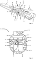
- the surgical instrument 1 shown is intended for use in minimally invasive surgery. It has a tubular hollow shaft 2 with a pair of tongs 3 at one end.
- the pliers 3 have two pivotable jaws 4 which can be pivoted together and apart with a wire as the core 5 which can be displaced in the hollow shaft 2 .
- a section of the hollow shaft 2 is cut out so that the core 5 is visible.
- the hollow shaft 2 goes through.
- the surgical instrument 1 can, for example, be scissors with two pivotable blades have (not shown).
- the invention is not limited to pliers 3 or scissors.
- the pliers 3 or scissors can also have only one pivoting jaw 4 or blade and one fixed jaw or blade.
- the surgical instrument 1 can, for example, also have two parallel shanks, in particular abutting one another and displaceable relative to one another in their longitudinal direction, which are both displaceable or one of which is displaceable and the other fixed (not shown).
- the surgical instrument 1 has an actuating unit 6 with a base holder 7, which figure 2 is shown as a single part.
- the base holder 7 is in the form of a strip with a slot 8 in a central region.
- the base holder 7 has a piece of pipe 26 in which the end of the hollow shaft 2 is attached in a detachable and exchangeable manner.
- a designated part, referred to here as a sliding block 9 is guided in a displaceable manner coaxially with the hollow shaft 2, on or in which the core 5 is detachably and exchangeably fastened.
- the actuating unit 6 has two handles 10 which, in the illustrated, non-actuated position of the surgical instrument 1, are V-shaped at an angle and which can be pressed together to actuate the surgical instrument 1 until they run parallel to one another on the strip-shaped base holder 7 issue. It is not necessary for the two handles 10 to be compressible until they rest against the base holder 7, but it is sufficient that an angle of the V at which the two handles 10 are in relation to one another can be reduced or at least changed. It is also possible to have handles 10 that can be moved in other ways than by pivoting. In the exemplary embodiment, the two handles 10 are semi-cylindrical or part-cylindrical shell-shaped.
- the handles 10 are in figure 1 with handle scales with a hole pattern and in figures 2 and 7 drawn without the grip panels.
- the two handles 10 are formed at one end in the manner of leaf springs and are fixed to the base holder 7 of the operating unit 6 so that they can pivot and pivot into the illustrated V-position when they are not subjected to a force.
- the two handles 10 are attached to an end of the base holder 7 of the actuating unit 6 that is remote from the hollow shaft 2, but they can also be attached to the end of the base holder 7 to which the hollow shaft 2 is attached (not shown), so that an apex of the V formed by the two handles 10 is at the end of the base holder 7 to which the hollow shank 2 is attached, rather than at the end remote from the hollow shank 2 as shown.
- an operating unit with only one movable handle 10, in which case the base holder 7 of the operating unit 6 or a fixed handle forms a counter-handle 11 (not shown).
- the base holder 7 of the operating unit 6 or a fixed handle forms a counter-handle 11 (not shown).
- the two handles 10 can be referred to as counter-handle 11, preferably the pivotable or generally the movable handle 10 is referred to as handle 10 and the other handle 10 as counter-handle 11, regardless of whether it is movable or fixed.
- actuation unit 6 angled like a pistol grip on the hollow shank 2 (not shown), which, however, requires an angular deflection to move the core 5 in the hollow shank 2 to actuate the surgical instrument 1 .
- the actuating unit 6 has two pivoted levers 12 , one end of which pivots on the handles 10 and the other ends pivot on the sliding block 9 .
- the two pivoting levers 12 are V-shaped from the base holder 7 at a more obtuse angle than the handles 10 apart.
- the direction of displacement is chosen so that when the handles 10 are pressed together, the jaws 4 of the pliers 3 pivot together. This direction of movement will referred to here as the actuation direction or actuation of the surgical instrument 1 .
- the two pivoting levers 12 By arranging the two pivoting levers 12 in an inverted V-shape as shown, i.e. an apex of the V of the pivoting lever 12 faces the hollow shaft 2 instead of facing away, the direction of displacement of the sliding block 9 can be reversed when the handles 10 are pressed together (not shown).
- the pivoting levers 12 are arranged close to free ends of the handles 10 which are remote from one another, although this is not essential for the invention.
- a locking piece 13 is arranged on one of the two handles 10 and a latch 14 is arranged opposite the locking piece 13 on the other handle 10, which is also referred to here as a counter-handle 11.
- figure 3 shows the closing piece 13 and the case 14 as individual parts in the position to one another which they have when the surgical instrument 1 is not actuated, which the Figures 1 and 2 show. In this position, the push-push locking mechanism 15 is unlocked.
- the terms "locking piece” and "latch” are borrowed from a door lock.
- the closing piece 13 and the catch 14 form a push-push locking mechanism 15 or parts of the push-push locking mechanism 15 of the surgical instrument 1 according to the invention.
- the latch 14 has a lenticular cross-section which is inclined to a movement plane of the handles 10 and to a deflection direction of the latch 10 and is arranged in one piece at one end of a lever 18 which is pivotably mounted on a latch holder 19 .
- a pivot axis of the lever 18 runs in or parallel to the plane of movement of the handles 10 or tangential to a circle concentric to a pivot axis of the handles 10 .
- the lever 18 can thus be pivoted in both directions transversely to the plane of movement of the handles 10 and the latch 14 can be deflected in both directions transversely to the plane of movement of the handles 10 .
- the closing piece 13 is pivotable in addition to the latch 14 or exclusively in both directions.
- a spring wire is arranged as a return spring 20 of the latch 14, the latch 14 remote end is fixed to the latch holder 19 and the latch 14 end close to the lever 18.
- the spring wire forming the return spring 20 is straight, although this is not essential for the invention. If the case 14 is deflected, no matter in which direction, it tensions the return spring 20, which moves the case 14 back into a non-directed basic position when it is free to move.
- the end of the lever 18 that has the latch 14 reaches through a slot in the latch holder 19 that runs in the pivoting direction of the lever 18 and in the deflection direction of the latch 14 near an engagement point with the closing piece 13 forms.
- the closing piece 13 and the latch holder 19 have mutually aligned fastening holes 22, at which they are screwed to the handles 10, that is to say they are fastened to the handles 10. Strictly speaking, the fastening holes 22 of the closing piece 13 and the latch holder 19 are located on an arc of a circle around the pivot axis of the handles 10. The two handles 10 can thus be of the same design.
- the case holder 19 with the case 14 having, pivotable lever 18 and the return spring 20 forms a preassembled assembly that can be attached as a whole to the inside of one of the two handles 10.
- the closing piece 13 has a hook 16 protruding in the direction of the latch 14 with an inclined surface 17 on an outer side of the hook 16, which in figure 4 is seen, which shows a cross-section through the hook 16 of the striker 13 and an end view of the lenticular, inclined latch 14 shows.
- the inclined surface 17 crosses the plane of movement of the handles 10 or one to the plane of movement
- the plane parallel to the handles 10 in which the latch 14 is located when undeflected is at an acute angle.
- the hook 16 can also be understood as the closing piece 13 in the actual sense.
- the catch 14 approaches as shown in FIG figure 4 shown the hook 16 of the closing piece 13 in the plane of movement of the handles 10 or the plane parallel to the plane of movement of the handles 10 until the latch 14 abuts against the hook 16 from the outside.
- the hook 16 deflects the catch 14 to allow the catch 14 to pass the hook 16, thereby tensioning the return spring 20.
- the passage of the catch 14 past the hook 16 of the striker 13 can also be referred to as stepping of the latch 14 on the locking piece 13.
- the tensioned return spring 20 moves the latch 14 counter to its deflection back in the direction of its non-disengaged basic position, so that the latch 14 reaches the hook 16, which is called the engagement of the Case 14 can be understood with the closing piece 13.
- This position which is referred to here as the locked position of the latch 14 or as the locked position of the push-push locking mechanism 15, is in figure 4 with dashed lines and in figure 5 drawn.
- the push-push locking mechanism 15 holds the two handles 10 in the pushed-together position, ie pivoted to the base holder 7, and thus holds the surgical instrument 1 in the actuated position.
- the jaws 4 of the pliers 3 are pressed together.
- the slot in the latch holder 19, which forms the abutment 21 for the latch 14, supports the latch 14, which is in engagement with the hook 16 of the closing piece 13 when the push-push locking mechanism 15 is locked, in a closing direction, i.e. against the handles 10 moving apart away.
- the abutment 21 supports the latch 14 near its point of engagement with the hook 16 of the locking piece 13 and thus near its point of engagement on the closing piece 13, whereby the locked latch 14 is well supported and the lever 18 is relieved.
- the two handles 10 are pressed together again a short distance so that the latch 14, as in figure 4 to see, from the hook 16 of the closing piece 13 is lifted.
- the restoring spring 20 which is still or again tensioned, pivots the latch 14 into its non-deflected basic position. If the handles 10 are now released, they spring apart because of their design as leaf springs.
- the latch 14 reaches the inclined surface 17 on the outside of the hook 16, which deflects the latch 14 in the opposite direction as when the push-push locking mechanism 15 is closed and locked, thereby tensioning the return spring 20.
- the latch 14 occurs again when released in the opposite direction as when closing or locking on the hook 16 of the locking piece 13 and thus past the locking piece 13, the handles 10 pivot apart into their original basic position, move the soul via the pivoted lever 12 and the sliding block 9 5 in the hollow shaft 2 and thereby open the jaws 4 of the pliers 3.
- the tensioned return spring 20 swings the latch 14 back into its non-deflected basic position, so that when it is pressed together again of the handles 10, the push-push locking mechanism 15 locks the surgical instrument 1 back into the actuated position as described above.
- figure 6 shows a modified assembly with the latch 14 at an angle to an opposite side as in FIG Figures 1 to 5 : here, at the end of the lever 18, three latches 14 are offset from one another in the direction of movement of the handles 10, as a result of which the push-push locking mechanism 15 can be locked in three positions.
- the jaws 4 of the pliers 3 can be pivoted together to different extents and/or held clamped against one another with different clamping forces. Designs with two or more than three traps 14 (not shown) are also possible.
- the surgical instrument 1 can have a closing piece with several arranged offset to one another in the direction of movement of the handles 10 Have hooks 16 or a plurality of closing pieces 13 offset from one another in the direction of movement of the handles 10 (not shown).
- a modification of the surgical instrument 1 shows figure 7 : there, the surgical instrument 1 according to the invention also has an unlocking device 23, which is used in particular for the in figure 6
- the embodiment shown with several latches 14 makes sense because the push-push locking mechanism 15 can be unlocked in any locking position and does not have to be actuated beyond a last locking position before the push-push locking mechanism 15 unlocks itself automatically, as described above .
- the unlocking device 23 is also useful if the surgical instrument 1 is to be able to be used in an automatically locking and non-locking manner.
- the unlocking device 23 has an unlocking lever 24 which is arranged pivotably at the free end of one of the two handles 10 . An arrangement of the release lever 24 elsewhere is possible (not shown).
- the unlocking lever 24 is - in the exemplary embodiment - connected by means of a metal strip 25 in an articulated manner to the lever 18 of the latch 14 .
- the metal strip 25 is articulated at a distance from the pivot axis on the unlocking lever 24 and eccentrically and articulated on one side of the lever 18, so that by pulling on the metal strip 25 the lever 18 is deflected to one side and thereby the latch 14 is deflected in one direction.
- the direction of deflection is the same as when locking, so that when the latch 14 is engaged with the hook 16 of the closing piece 13 and the push-push locking mechanism 15 is locked, the latch 14 comes free from the hook 16 to the side.
- the train on the sheet metal strip 25 for unlocking the push-push locking mechanism 15 is generated by pivoting the unlocking lever 24 .
- the sheet metal strip 25 is articulated on the unlocking lever 24 in such a way that when unlocking the point of articulation of the sheet metal strip 25 on the unlocking lever 24 passes over an imaginary straight line through the point of articulation of the metal strip 25 on the lever 18 of the latch 14 and through the pivot axis of the unlocking lever 24.
- This enables an inherently stable unlocking position of the unlocking device, which keeps the push-push locking mechanism 15 unlocked without having to hold the unlocking lever 24. If the unlocking lever 24 is pivoted less far, the unlocking is not stable, but the push-push locking mechanism 15 locks automatically when the unlocking lever 24 is released.
- the unlocking device can also be designed without a stable unlocking position.
- figure 7 shows the surgical instrument 1 in a perspective view with a view as in FIG figure 6 on a compared with the Figures 1 to 5 opposite side of the instrument 1, so that the sheet metal strip 25 located there of the unlocking device 23 is visible.
Landscapes
- Health & Medical Sciences (AREA)
- Surgery (AREA)
- Life Sciences & Earth Sciences (AREA)
- Biomedical Technology (AREA)
- Nuclear Medicine, Radiotherapy & Molecular Imaging (AREA)
- Engineering & Computer Science (AREA)
- Ophthalmology & Optometry (AREA)
- Heart & Thoracic Surgery (AREA)
- Medical Informatics (AREA)
- Molecular Biology (AREA)
- Animal Behavior & Ethology (AREA)
- General Health & Medical Sciences (AREA)
- Public Health (AREA)
- Veterinary Medicine (AREA)
- Surgical Instruments (AREA)
Priority Applications (1)
| Application Number | Priority Date | Filing Date | Title |
|---|---|---|---|
| EP20188396.4A EP3944827B1 (fr) | 2020-07-29 | 2020-07-29 | Instrument chirurgical à mécanique de verrouillage push-push |
Applications Claiming Priority (1)
| Application Number | Priority Date | Filing Date | Title |
|---|---|---|---|
| EP20188396.4A EP3944827B1 (fr) | 2020-07-29 | 2020-07-29 | Instrument chirurgical à mécanique de verrouillage push-push |
Publications (2)
| Publication Number | Publication Date |
|---|---|
| EP3944827A1 true EP3944827A1 (fr) | 2022-02-02 |
| EP3944827B1 EP3944827B1 (fr) | 2023-01-11 |
Family
ID=71846292
Family Applications (1)
| Application Number | Title | Priority Date | Filing Date |
|---|---|---|---|
| EP20188396.4A Active EP3944827B1 (fr) | 2020-07-29 | 2020-07-29 | Instrument chirurgical à mécanique de verrouillage push-push |
Country Status (1)
| Country | Link |
|---|---|
| EP (1) | EP3944827B1 (fr) |
Cited By (4)
| Publication number | Priority date | Publication date | Assignee | Title |
|---|---|---|---|---|
| CN115590598A (zh) * | 2022-09-27 | 2023-01-13 | 吉林大学(Cn) | 一种微创手术器械 |
| CN116690640A (zh) * | 2023-06-29 | 2023-09-05 | 国网湖南省电力有限公司 | 一种斗臂车机械臂辅助装置 |
| DE102022116654A1 (de) | 2022-07-04 | 2024-01-04 | Ivonne Tschida-Kelch | Chirurgisches Instrument |
| EP4463087A4 (fr) * | 2022-02-09 | 2025-07-16 | Lsi Solutions Inc | Dispositif de collecte de récipients |
Citations (7)
| Publication number | Priority date | Publication date | Assignee | Title |
|---|---|---|---|---|
| US5618306A (en) * | 1994-02-14 | 1997-04-08 | Heartport, Inc. | Endoscopic microsurgical instruments and methods |
| DE19841249C1 (de) * | 1998-09-09 | 2000-05-25 | Aesculap Ag & Co Kg | Zangen- oder pinzettenförmiges chirurgisches Instrument |
| US6322578B1 (en) * | 1997-07-14 | 2001-11-27 | Heartport, Inc. | Endoscopic microsurgical instruments |
| DE10314072A1 (de) * | 2003-03-28 | 2004-10-21 | Aesculap Ag & Co. Kg | Chirurgisches Instrument |
| US20130247333A1 (en) * | 2012-03-21 | 2013-09-26 | Tri-Medics | Instrument handle, a device having the instrument handle, and a method of manufacturing the instrument handle |
| EP2792319A1 (fr) | 2013-04-17 | 2014-10-22 | Jakoubek Medizintechnik Gmbh | Élément d'actionnement et paire de bascules pour un élément d'actionnement |
| US20180153535A1 (en) * | 2016-12-02 | 2018-06-07 | Jeffrey I. Lasner | Handle for microsurgical instruments |
-
2020
- 2020-07-29 EP EP20188396.4A patent/EP3944827B1/fr active Active
Patent Citations (7)
| Publication number | Priority date | Publication date | Assignee | Title |
|---|---|---|---|---|
| US5618306A (en) * | 1994-02-14 | 1997-04-08 | Heartport, Inc. | Endoscopic microsurgical instruments and methods |
| US6322578B1 (en) * | 1997-07-14 | 2001-11-27 | Heartport, Inc. | Endoscopic microsurgical instruments |
| DE19841249C1 (de) * | 1998-09-09 | 2000-05-25 | Aesculap Ag & Co Kg | Zangen- oder pinzettenförmiges chirurgisches Instrument |
| DE10314072A1 (de) * | 2003-03-28 | 2004-10-21 | Aesculap Ag & Co. Kg | Chirurgisches Instrument |
| US20130247333A1 (en) * | 2012-03-21 | 2013-09-26 | Tri-Medics | Instrument handle, a device having the instrument handle, and a method of manufacturing the instrument handle |
| EP2792319A1 (fr) | 2013-04-17 | 2014-10-22 | Jakoubek Medizintechnik Gmbh | Élément d'actionnement et paire de bascules pour un élément d'actionnement |
| US20180153535A1 (en) * | 2016-12-02 | 2018-06-07 | Jeffrey I. Lasner | Handle for microsurgical instruments |
Cited By (4)
| Publication number | Priority date | Publication date | Assignee | Title |
|---|---|---|---|---|
| EP4463087A4 (fr) * | 2022-02-09 | 2025-07-16 | Lsi Solutions Inc | Dispositif de collecte de récipients |
| DE102022116654A1 (de) | 2022-07-04 | 2024-01-04 | Ivonne Tschida-Kelch | Chirurgisches Instrument |
| CN115590598A (zh) * | 2022-09-27 | 2023-01-13 | 吉林大学(Cn) | 一种微创手术器械 |
| CN116690640A (zh) * | 2023-06-29 | 2023-09-05 | 国网湖南省电力有限公司 | 一种斗臂车机械臂辅助装置 |
Also Published As
| Publication number | Publication date |
|---|---|
| EP3944827B1 (fr) | 2023-01-11 |
Similar Documents
| Publication | Publication Date | Title |
|---|---|---|
| EP3944827B1 (fr) | Instrument chirurgical à mécanique de verrouillage push-push | |
| DE3103352C2 (de) | Pinzetten- oder zangenförmiges chirurgisches Instrument | |
| EP2578171B1 (fr) | Instrument chirurgical | |
| EP0951868B1 (fr) | Ecarteur chirurgical | |
| EP2056727A1 (fr) | Pince chirurgicale | |
| EP2056415A2 (fr) | Pince à dénuder | |
| DE102010006846A1 (de) | Chirurgisches Instrument | |
| DE202009003869U1 (de) | Chirurgisches Instrument | |
| DE102014102606A1 (de) | Mikrochirurgisches Halte- und/oder Schneidinstrument | |
| EP3581057A1 (fr) | Boucle, en particulier boucle de ceinture | |
| EP0963737B1 (fr) | Pince pour broches chirurgicales | |
| DE2732575C2 (de) | Verriegelungsvorrichtung | |
| DE102009056099A1 (de) | Chirurgisches Instrument | |
| DE1531344C3 (de) | Vorrichtung zum Ziehen und/oder Heben eines Seiles | |
| EP4289574A1 (fr) | Couteau | |
| DE69607645T2 (de) | Mehrzweckzange | |
| DE19931953A1 (de) | Beschlag zur Lagerung eines Endes einer Latte eines Lattenrahmens | |
| DE19747043C2 (de) | Endoskopisches Instrument | |
| DE602005000110T2 (de) | Mechanismus zum Öffnen und Schliessen einer Kraftfahrzeugtür | |
| EP0928237B1 (fr) | Cisaille pour tiges filetees ou mats | |
| DE102020129618A1 (de) | Medizinisches Instrument, modulares Instrumentensystem und Verfahren zum Lagern eines medizinischen Instruments | |
| DE202009017555U1 (de) | Schiebeschaftinstrument | |
| DE19602511C2 (de) | Chirurgisches Instrument | |
| EP1961290A1 (fr) | Dispositif de verrouillage pour ciseaux | |
| EP2926746A1 (fr) | Instrument chirurgical |
Legal Events
| Date | Code | Title | Description |
|---|---|---|---|
| PUAI | Public reference made under article 153(3) epc to a published international application that has entered the european phase |
Free format text: ORIGINAL CODE: 0009012 |
|
| STAA | Information on the status of an ep patent application or granted ep patent |
Free format text: STATUS: REQUEST FOR EXAMINATION WAS MADE |
|
| 17P | Request for examination filed |
Effective date: 20210827 |
|
| AK | Designated contracting states |
Kind code of ref document: A1 Designated state(s): AL AT BE BG CH CY CZ DE DK EE ES FI FR GB GR HR HU IE IS IT LI LT LU LV MC MK MT NL NO PL PT RO RS SE SI SK SM TR |
|
| GRAP | Despatch of communication of intention to grant a patent |
Free format text: ORIGINAL CODE: EPIDOSNIGR1 |
|
| STAA | Information on the status of an ep patent application or granted ep patent |
Free format text: STATUS: GRANT OF PATENT IS INTENDED |
|
| RBV | Designated contracting states (corrected) |
Designated state(s): AL AT BE BG CH CY CZ DE DK EE ES FI FR GB GR HR HU IE IS IT LI LT LU LV MC MK MT NL NO PL PT RO RS SE SI SK SM TR |
|
| INTG | Intention to grant announced |
Effective date: 20220725 |
|
| GRAS | Grant fee paid |
Free format text: ORIGINAL CODE: EPIDOSNIGR3 |
|
| GRAA | (expected) grant |
Free format text: ORIGINAL CODE: 0009210 |
|
| STAA | Information on the status of an ep patent application or granted ep patent |
Free format text: STATUS: THE PATENT HAS BEEN GRANTED |
|
| AK | Designated contracting states |
Kind code of ref document: B1 Designated state(s): AL AT BE BG CH CY CZ DE DK EE ES FI FR GB GR HR HU IE IS IT LI LT LU LV MC MK MT NL NO PL PT RO RS SE SI SK SM TR |
|
| REG | Reference to a national code |
Ref country code: GB Ref legal event code: FG4D Free format text: NOT ENGLISH |
|
| REG | Reference to a national code |
Ref country code: CH Ref legal event code: EP |
|
| REG | Reference to a national code |
Ref country code: DE Ref legal event code: R096 Ref document number: 502020002340 Country of ref document: DE |
|
| REG | Reference to a national code |
Ref country code: IE Ref legal event code: FG4D Free format text: LANGUAGE OF EP DOCUMENT: GERMAN |
|
| REG | Reference to a national code |
Ref country code: AT Ref legal event code: REF Ref document number: 1542936 Country of ref document: AT Kind code of ref document: T Effective date: 20230215 |
|
| REG | Reference to a national code |
Ref country code: LT Ref legal event code: MG9D |
|
| REG | Reference to a national code |
Ref country code: NL Ref legal event code: MP Effective date: 20230111 |
|
| PG25 | Lapsed in a contracting state [announced via postgrant information from national office to epo] |
Ref country code: NL Free format text: LAPSE BECAUSE OF FAILURE TO SUBMIT A TRANSLATION OF THE DESCRIPTION OR TO PAY THE FEE WITHIN THE PRESCRIBED TIME-LIMIT Effective date: 20230111 |
|
| P01 | Opt-out of the competence of the unified patent court (upc) registered |
Effective date: 20230529 |
|
| PG25 | Lapsed in a contracting state [announced via postgrant information from national office to epo] |
Ref country code: RS Free format text: LAPSE BECAUSE OF FAILURE TO SUBMIT A TRANSLATION OF THE DESCRIPTION OR TO PAY THE FEE WITHIN THE PRESCRIBED TIME-LIMIT Effective date: 20230111 Ref country code: PT Free format text: LAPSE BECAUSE OF FAILURE TO SUBMIT A TRANSLATION OF THE DESCRIPTION OR TO PAY THE FEE WITHIN THE PRESCRIBED TIME-LIMIT Effective date: 20230511 Ref country code: NO Free format text: LAPSE BECAUSE OF FAILURE TO SUBMIT A TRANSLATION OF THE DESCRIPTION OR TO PAY THE FEE WITHIN THE PRESCRIBED TIME-LIMIT Effective date: 20230411 Ref country code: LV Free format text: LAPSE BECAUSE OF FAILURE TO SUBMIT A TRANSLATION OF THE DESCRIPTION OR TO PAY THE FEE WITHIN THE PRESCRIBED TIME-LIMIT Effective date: 20230111 Ref country code: LT Free format text: LAPSE BECAUSE OF FAILURE TO SUBMIT A TRANSLATION OF THE DESCRIPTION OR TO PAY THE FEE WITHIN THE PRESCRIBED TIME-LIMIT Effective date: 20230111 Ref country code: HR Free format text: LAPSE BECAUSE OF FAILURE TO SUBMIT A TRANSLATION OF THE DESCRIPTION OR TO PAY THE FEE WITHIN THE PRESCRIBED TIME-LIMIT Effective date: 20230111 Ref country code: ES Free format text: LAPSE BECAUSE OF FAILURE TO SUBMIT A TRANSLATION OF THE DESCRIPTION OR TO PAY THE FEE WITHIN THE PRESCRIBED TIME-LIMIT Effective date: 20230111 |
|
| PG25 | Lapsed in a contracting state [announced via postgrant information from national office to epo] |
Ref country code: SE Free format text: LAPSE BECAUSE OF FAILURE TO SUBMIT A TRANSLATION OF THE DESCRIPTION OR TO PAY THE FEE WITHIN THE PRESCRIBED TIME-LIMIT Effective date: 20230111 Ref country code: PL Free format text: LAPSE BECAUSE OF FAILURE TO SUBMIT A TRANSLATION OF THE DESCRIPTION OR TO PAY THE FEE WITHIN THE PRESCRIBED TIME-LIMIT Effective date: 20230111 Ref country code: IS Free format text: LAPSE BECAUSE OF FAILURE TO SUBMIT A TRANSLATION OF THE DESCRIPTION OR TO PAY THE FEE WITHIN THE PRESCRIBED TIME-LIMIT Effective date: 20230511 Ref country code: GR Free format text: LAPSE BECAUSE OF FAILURE TO SUBMIT A TRANSLATION OF THE DESCRIPTION OR TO PAY THE FEE WITHIN THE PRESCRIBED TIME-LIMIT Effective date: 20230412 Ref country code: FI Free format text: LAPSE BECAUSE OF FAILURE TO SUBMIT A TRANSLATION OF THE DESCRIPTION OR TO PAY THE FEE WITHIN THE PRESCRIBED TIME-LIMIT Effective date: 20230111 |
|
| REG | Reference to a national code |
Ref country code: DE Ref legal event code: R097 Ref document number: 502020002340 Country of ref document: DE |
|
| PG25 | Lapsed in a contracting state [announced via postgrant information from national office to epo] |
Ref country code: SM Free format text: LAPSE BECAUSE OF FAILURE TO SUBMIT A TRANSLATION OF THE DESCRIPTION OR TO PAY THE FEE WITHIN THE PRESCRIBED TIME-LIMIT Effective date: 20230111 Ref country code: RO Free format text: LAPSE BECAUSE OF FAILURE TO SUBMIT A TRANSLATION OF THE DESCRIPTION OR TO PAY THE FEE WITHIN THE PRESCRIBED TIME-LIMIT Effective date: 20230111 Ref country code: EE Free format text: LAPSE BECAUSE OF FAILURE TO SUBMIT A TRANSLATION OF THE DESCRIPTION OR TO PAY THE FEE WITHIN THE PRESCRIBED TIME-LIMIT Effective date: 20230111 Ref country code: DK Free format text: LAPSE BECAUSE OF FAILURE TO SUBMIT A TRANSLATION OF THE DESCRIPTION OR TO PAY THE FEE WITHIN THE PRESCRIBED TIME-LIMIT Effective date: 20230111 Ref country code: CZ Free format text: LAPSE BECAUSE OF FAILURE TO SUBMIT A TRANSLATION OF THE DESCRIPTION OR TO PAY THE FEE WITHIN THE PRESCRIBED TIME-LIMIT Effective date: 20230111 |
|
| PLBE | No opposition filed within time limit |
Free format text: ORIGINAL CODE: 0009261 |
|
| STAA | Information on the status of an ep patent application or granted ep patent |
Free format text: STATUS: NO OPPOSITION FILED WITHIN TIME LIMIT |
|
| PG25 | Lapsed in a contracting state [announced via postgrant information from national office to epo] |
Ref country code: SK Free format text: LAPSE BECAUSE OF FAILURE TO SUBMIT A TRANSLATION OF THE DESCRIPTION OR TO PAY THE FEE WITHIN THE PRESCRIBED TIME-LIMIT Effective date: 20230111 |
|
| 26N | No opposition filed |
Effective date: 20231012 |
|
| PG25 | Lapsed in a contracting state [announced via postgrant information from national office to epo] |
Ref country code: SI Free format text: LAPSE BECAUSE OF FAILURE TO SUBMIT A TRANSLATION OF THE DESCRIPTION OR TO PAY THE FEE WITHIN THE PRESCRIBED TIME-LIMIT Effective date: 20230111 |
|
| PG25 | Lapsed in a contracting state [announced via postgrant information from national office to epo] |
Ref country code: MC Free format text: LAPSE BECAUSE OF FAILURE TO SUBMIT A TRANSLATION OF THE DESCRIPTION OR TO PAY THE FEE WITHIN THE PRESCRIBED TIME-LIMIT Effective date: 20230111 |
|
| PG25 | Lapsed in a contracting state [announced via postgrant information from national office to epo] |
Ref country code: MC Free format text: LAPSE BECAUSE OF FAILURE TO SUBMIT A TRANSLATION OF THE DESCRIPTION OR TO PAY THE FEE WITHIN THE PRESCRIBED TIME-LIMIT Effective date: 20230111 |
|
| REG | Reference to a national code |
Ref country code: CH Ref legal event code: PL |
|
| REG | Reference to a national code |
Ref country code: BE Ref legal event code: MM Effective date: 20230731 |
|
| PG25 | Lapsed in a contracting state [announced via postgrant information from national office to epo] |
Ref country code: LU Free format text: LAPSE BECAUSE OF NON-PAYMENT OF DUE FEES Effective date: 20230729 |
|
| PG25 | Lapsed in a contracting state [announced via postgrant information from national office to epo] |
Ref country code: LU Free format text: LAPSE BECAUSE OF NON-PAYMENT OF DUE FEES Effective date: 20230729 |
|
| REG | Reference to a national code |
Ref country code: IE Ref legal event code: MM4A |
|
| PG25 | Lapsed in a contracting state [announced via postgrant information from national office to epo] |
Ref country code: CH Free format text: LAPSE BECAUSE OF NON-PAYMENT OF DUE FEES Effective date: 20230731 |
|
| PG25 | Lapsed in a contracting state [announced via postgrant information from national office to epo] |
Ref country code: IT Free format text: LAPSE BECAUSE OF FAILURE TO SUBMIT A TRANSLATION OF THE DESCRIPTION OR TO PAY THE FEE WITHIN THE PRESCRIBED TIME-LIMIT Effective date: 20230111 Ref country code: FR Free format text: LAPSE BECAUSE OF NON-PAYMENT OF DUE FEES Effective date: 20230731 Ref country code: BE Free format text: LAPSE BECAUSE OF NON-PAYMENT OF DUE FEES Effective date: 20230731 |
|
| PG25 | Lapsed in a contracting state [announced via postgrant information from national office to epo] |
Ref country code: IE Free format text: LAPSE BECAUSE OF NON-PAYMENT OF DUE FEES Effective date: 20230729 |
|
| PG25 | Lapsed in a contracting state [announced via postgrant information from national office to epo] |
Ref country code: IE Free format text: LAPSE BECAUSE OF NON-PAYMENT OF DUE FEES Effective date: 20230729 |
|
| PG25 | Lapsed in a contracting state [announced via postgrant information from national office to epo] |
Ref country code: BG Free format text: LAPSE BECAUSE OF FAILURE TO SUBMIT A TRANSLATION OF THE DESCRIPTION OR TO PAY THE FEE WITHIN THE PRESCRIBED TIME-LIMIT Effective date: 20230111 |
|
| PG25 | Lapsed in a contracting state [announced via postgrant information from national office to epo] |
Ref country code: BG Free format text: LAPSE BECAUSE OF FAILURE TO SUBMIT A TRANSLATION OF THE DESCRIPTION OR TO PAY THE FEE WITHIN THE PRESCRIBED TIME-LIMIT Effective date: 20230111 |
|
| GBPC | Gb: european patent ceased through non-payment of renewal fee |
Effective date: 20240729 |
|
| PG25 | Lapsed in a contracting state [announced via postgrant information from national office to epo] |
Ref country code: GB Free format text: LAPSE BECAUSE OF NON-PAYMENT OF DUE FEES Effective date: 20240729 |
|
| PG25 | Lapsed in a contracting state [announced via postgrant information from national office to epo] |
Ref country code: CY Free format text: LAPSE BECAUSE OF FAILURE TO SUBMIT A TRANSLATION OF THE DESCRIPTION OR TO PAY THE FEE WITHIN THE PRESCRIBED TIME-LIMIT; INVALID AB INITIO Effective date: 20200729 |
|
| PG25 | Lapsed in a contracting state [announced via postgrant information from national office to epo] |
Ref country code: HU Free format text: LAPSE BECAUSE OF FAILURE TO SUBMIT A TRANSLATION OF THE DESCRIPTION OR TO PAY THE FEE WITHIN THE PRESCRIBED TIME-LIMIT; INVALID AB INITIO Effective date: 20200729 |
|
| PGFP | Annual fee paid to national office [announced via postgrant information from national office to epo] |
Ref country code: DE Payment date: 20250730 Year of fee payment: 6 |
|
| PGFP | Annual fee paid to national office [announced via postgrant information from national office to epo] |
Ref country code: AT Payment date: 20251020 Year of fee payment: 5 |