EP3941789B1 - Système d'essuie-glace pour pare-brise de véhicule - Google Patents
Système d'essuie-glace pour pare-brise de véhicule Download PDFInfo
- Publication number
- EP3941789B1 EP3941789B1 EP20702287.2A EP20702287A EP3941789B1 EP 3941789 B1 EP3941789 B1 EP 3941789B1 EP 20702287 A EP20702287 A EP 20702287A EP 3941789 B1 EP3941789 B1 EP 3941789B1
- Authority
- EP
- European Patent Office
- Prior art keywords
- wiper
- horizontal
- vehicle windshield
- windshield
- horizontally extending
- Prior art date
- Legal status (The legal status is an assumption and is not a legal conclusion. Google has not performed a legal analysis and makes no representation as to the accuracy of the status listed.)
- Active
Links
- 239000012530 fluid Substances 0.000 claims description 51
- 239000011248 coating agent Substances 0.000 claims description 7
- 238000000576 coating method Methods 0.000 claims description 7
- 239000000696 magnetic material Substances 0.000 claims description 3
- 239000002184 metal Substances 0.000 claims description 3
- 239000007788 liquid Substances 0.000 description 7
- XLYOFNOQVPJJNP-UHFFFAOYSA-N water Substances O XLYOFNOQVPJJNP-UHFFFAOYSA-N 0.000 description 3
- 240000004752 Laburnum anagyroides Species 0.000 description 1
- 238000004140 cleaning Methods 0.000 description 1
- 230000007812 deficiency Effects 0.000 description 1
- 230000005389 magnetism Effects 0.000 description 1
- 238000012986 modification Methods 0.000 description 1
- 230000004048 modification Effects 0.000 description 1
- 239000000126 substance Substances 0.000 description 1
- 230000000007 visual effect Effects 0.000 description 1
Images


Classifications
-
- B—PERFORMING OPERATIONS; TRANSPORTING
- B60—VEHICLES IN GENERAL
- B60S—SERVICING, CLEANING, REPAIRING, SUPPORTING, LIFTING, OR MANOEUVRING OF VEHICLES, NOT OTHERWISE PROVIDED FOR
- B60S1/00—Cleaning of vehicles
- B60S1/02—Cleaning windscreens, windows or optical devices
- B60S1/04—Wipers or the like, e.g. scrapers
- B60S1/44—Wipers or the like, e.g. scrapers the wiper blades having other than swinging movement, e.g. rotary
-
- B—PERFORMING OPERATIONS; TRANSPORTING
- B60—VEHICLES IN GENERAL
- B60S—SERVICING, CLEANING, REPAIRING, SUPPORTING, LIFTING, OR MANOEUVRING OF VEHICLES, NOT OTHERWISE PROVIDED FOR
- B60S1/00—Cleaning of vehicles
- B60S1/02—Cleaning windscreens, windows or optical devices
- B60S1/04—Wipers or the like, e.g. scrapers
- B60S1/32—Wipers or the like, e.g. scrapers characterised by constructional features of wiper blade arms or blades
- B60S1/34—Wiper arms; Mountings therefor
- B60S1/3402—Wiper arms; Mountings therefor with means for obtaining particular wiping patterns
- B60S1/3406—Wiper arms; Mountings therefor with means for obtaining particular wiping patterns the wiper blades being rotated with respect to the wiper arms around an axis perpendicular to the wiped field
-
- B—PERFORMING OPERATIONS; TRANSPORTING
- B60—VEHICLES IN GENERAL
- B60S—SERVICING, CLEANING, REPAIRING, SUPPORTING, LIFTING, OR MANOEUVRING OF VEHICLES, NOT OTHERWISE PROVIDED FOR
- B60S1/00—Cleaning of vehicles
- B60S1/02—Cleaning windscreens, windows or optical devices
- B60S1/04—Wipers or the like, e.g. scrapers
- B60S1/0452—Position of the wipers relative to the vehicle
-
- B—PERFORMING OPERATIONS; TRANSPORTING
- B60—VEHICLES IN GENERAL
- B60S—SERVICING, CLEANING, REPAIRING, SUPPORTING, LIFTING, OR MANOEUVRING OF VEHICLES, NOT OTHERWISE PROVIDED FOR
- B60S1/00—Cleaning of vehicles
- B60S1/02—Cleaning windscreens, windows or optical devices
- B60S1/04—Wipers or the like, e.g. scrapers
- B60S1/32—Wipers or the like, e.g. scrapers characterised by constructional features of wiper blade arms or blades
- B60S1/34—Wiper arms; Mountings therefor
- B60S1/3402—Wiper arms; Mountings therefor with means for obtaining particular wiping patterns
- B60S1/3404—Wiper arms; Mountings therefor with means for obtaining particular wiping patterns the wiper blades being moved substantially parallel with themselves
-
- B—PERFORMING OPERATIONS; TRANSPORTING
- B60—VEHICLES IN GENERAL
- B60S—SERVICING, CLEANING, REPAIRING, SUPPORTING, LIFTING, OR MANOEUVRING OF VEHICLES, NOT OTHERWISE PROVIDED FOR
- B60S1/00—Cleaning of vehicles
- B60S1/02—Cleaning windscreens, windows or optical devices
- B60S1/04—Wipers or the like, e.g. scrapers
- B60S1/32—Wipers or the like, e.g. scrapers characterised by constructional features of wiper blade arms or blades
- B60S1/34—Wiper arms; Mountings therefor
- B60S1/3463—Means to press blade onto screen
-
- B—PERFORMING OPERATIONS; TRANSPORTING
- B60—VEHICLES IN GENERAL
- B60S—SERVICING, CLEANING, REPAIRING, SUPPORTING, LIFTING, OR MANOEUVRING OF VEHICLES, NOT OTHERWISE PROVIDED FOR
- B60S1/00—Cleaning of vehicles
- B60S1/02—Cleaning windscreens, windows or optical devices
- B60S1/04—Wipers or the like, e.g. scrapers
- B60S1/32—Wipers or the like, e.g. scrapers characterised by constructional features of wiper blade arms or blades
- B60S1/38—Wiper blades
- B60S2001/3812—Means of supporting or holding the squeegee or blade rubber
Definitions
- the present disclosure relates to a wiper system for a vehicle windshield.
- the disclosure also relates to vehicle comprising such a wiper system.
- the wiper system of the present disclosure is thus applicable on vehicles, in particularly low, medium and heavy duty vehicles commonly referred to as trucks.
- trucks in particularly low, medium and heavy duty vehicles commonly referred to as trucks.
- the invention will mainly be described in relation to a truck, it may also be applicable for other type of vehicles, such as e.g. on a rear window of a car, etc.
- Conventional wiper systems for vehicles are often arranged as two pendulum wipers connected to the vehicle chassis at a position below the vehicle windshield.
- the two pendulum wipers rotate at the lower portion of the windshield when wiping the windshield.
- the two pendulum wipers may be arranged to move in the same direction or in opposite direction to each other.
- a further solution is to use a horizontal wiper which is arranged to move vertically from a lower position of the windshield to an upper position thereof.
- a document describing such a wiper is DE 41 39 457 .
- the solution presented in DE 41 39 457 is still faced with the problem of sufficiently wiping a windshield which is to some extent curved in the vertical direction.
- a wiper system for a vehicle windshield comprising a first wiper arm and a second wiper arm, the first and second wiper arms being movable in at least a vertical direction; and a horizontal wiper arrangement comprising a wiper blade arranged to wipe the surface of the vehicle windshield, the horizontal wiper arrangement further comprising a horizontally extending wiper guide element connected to the wiper blade for arranging the wiper blade to extend between vertical end sides of the vehicle windshield, the first and second wiper arms being connected to the horizontally extending wiper guide element for vertically moving the horizontal wiper arrangement between a vertically lower position of the vehicle windshield and a vertically higher position of the vehicle windshield; wherein the wiper system further comprises a plurality of spring elements connecting the wiper blade to the horizontally extending wiper guide element, the plurality of spring elements being spaced apart from each other along the length of the horizontally extending wiper guide element, wherein the spring elements are arranged to force the wiper blade towards the
- first and second wiper arms can move the horizontal wiper arrangement in the vertical direction. This can be accomplished by e.g. using a rotatable wiper which is rotatably connected to the vehicle body. The vertical motion can also be achieved using a telescopic arrangement connected to the first and second wiper arms. Other alternatives are also conceivable.
- the first and second wiper arms can be connected at a position below the vehicle windshield, or at a position above the vehicle windshield.
- the vertical end sides of the vehicle windshield must not necessarily be the most outer end portions of the windshield.
- the vertically lower position and vertically higher position must not necessarily be the lowest position and the highest position of the windshield.
- the horizontal wiper arrangement can be arranged to wipe almost the entire surface of the windshield.
- a horizontal wiper arrangement is advantageous as a larger area of the vehicle windshield can be wiped when e.g. driving the vehicle in rainy conditions.
- a horizontal wiper arrangement can be formed to follow a curved design of the vehicle windshield, thus improving the overall wiping characteristics.
- a uniformly distributed force towards the windshield can be obtained. In other words, the wiper blade is uniformly pushed towards the windshield which will improve the overall wiping of water from the windshield.
- the plurality of spring elements may be uniformly spaced apart from each other.
- the plurality of spring elements may also be divided into two or more sets of spring elements, where the spring elements of each set of spring elements are uniformly spaced apart from each other.
- each of the first and second wiper arms may be pivotably connected to the horizontally extending wiper guide element for rotation around a geometric rotation axis configured to be substantially perpendicular to a plane defined by the surface of the windshield.
- each of the first and second wiper arms may comprise a pivotable portion at an opposite end compared to the connection of the horizontally extending wiper guide element, wherein the first and second wiper arms are rotatably connectable to a portion of the vehicle chassis.
- first and second wiper arms operate in a similar manner as conventional rotatable wiper blades.
- An advantage is that the horizontal wiper arrangement can be connected to the "old" wiping system, preferably to a system using wiper arms moving in opposite directions.
- each of the first and second wiper arms may comprise a retractable portion for extending and retracting the first and second wiper arms when vertically moving the horizontal wiper arrangement between the vertically lower and upper positions of the vehicle windshield.
- the retractable portion may preferably be a telescopic arrangement which is arranged to retract when the horizontal wiper arrangement moves away from the connecting portion to the vehicle chassis.
- the wiper system may further comprise a horizontal sliding portion, wherein one of the end portions of each of the first and second wiper arms is slidably connected to the horizontal sliding portion for being horizontally movable when vertically moving the horizontal wiper arrangement between the vertically lower and upper positions of the vehicle windshield.
- the wiper system may further comprise an electric motor connected to each of the first and second wiper arms for controlling the vertical motion of the horizontal wiper arrangement.
- the electric motor is preferably used for operating the first and second wiper arms to move horizontally along the horizontal sliding portion.
- the first and second wiper arms may comprise a respective wiper blade arranged to slide against the surface of the vehicle windshield when vertically moving the horizontal wiper arrangement between the vertically lower and upper positions of the vehicle windshield.
- first and second wiper arms contribute to the wiping of the vehicle windshield, thus improving the overall wiping of e.g. rain.
- the wiper blade is connected to the horizontally extending wiper guide element at an angle in a vertically downward direction from a center portion of the horizontally extending wiper guide element towards an end portion thereof.
- the horizontally extending wiper guide element may comprise a horizontal wiper guide rail and a fluid reservoir in fluid communication with the horizontal wiper guide rail, wherein each spring element is connected to a piston of the horizontal wiper guide rail, the piston being exposed to a fluid pressure from the fluid in the fluid reservoir.
- the fluid from the fluid reservoir will provide a pressure towards the pistons thereby forcing the wiper blade towards the windshield.
- a fluid arrangement will enable for a substantially distributed force of the wiper blade towards the windshield.
- the fluid reservoir may comprise a cylinder for housing the fluid, and a reservoir piston for forcing the fluid towards the horizontal wiper guide rail.
- the cylinder may be arranged as a "dead mass" which, by means of gravitational forces, pushes the fluid towards the guide rail and thus towards the pistons connected to the spring elements.
- the fluid reservoir may comprise a diameter larger than a diameter of the horizontal wiper guide rail.
- the fluid pressure will be higher in the horizontal wiper guide rail than in the fluid reservoir which will secure that the wiper blade is exposed to a proper pressure for forcing being forced towards the vehicle windshield.
- the spring elements may comprise a metal of magnetic material, the wiper system further comprising a transparent magnetic coating connectable to a surface of the windshield.
- the transparent magnetic coating is preferably connected to the inner surface of the vehicle windshield. However, it can also be connected to the outer surface as well.
- a vehicle comprising a vehicle windshield and a wiper system according to any one of the embodiments described above in relation to the first aspect, wherein the wiper blade is arranged in abutment with the vehicle windshield.
- a vehicle 10 in the form of a truck.
- the vehicle 10 comprises a vehicle windshield 102, which is a front vehicle windshield 102.
- the vehicle 10 further comprises a wiper system 100 for cleaning the vehicle windshield 102 during e.g. rainy weather.
- the wiper system 100 comprises horizontal wiper arrangement 300 movable in a substantial pure vertical direction of the vehicle windshield 102.
- the wiper system is described in relation to a front vehicle windshield 102, it can also be arranged in connection to e.g. a rear windshield of a car, etc.
- the wiper system 100 comprises a horizontal wiper arrangement 300.
- the horizontal wiper arrangement 300 comprises a wiper blade 302 which is arranged to wipe the surface of the vehicle windshield 102, and a horizontally extending wiper guide element 304 onto which the wiper blade is connected.
- the wiper blade 302 is thus arranged to extend between vertical end sides 502, 504 of the vehicle windshield 102.
- the wiper system 100 also comprises a first 104 and a second 106 wiper arm.
- the wiper arms 104, 106 are thus arranged move the horizontal wiper arrangement 300 in the vertical direction 200 between a vertically lower position 602 of the windshield and a vertically higher position 604 thereof.
- the first 104 and second 106 wiper arms are pivotably connected to the horizontally extending wiper guide element 304.
- the wiper arms 104, 106 are also pivotably connected to an actuation arrangement by means of a respective pivotable portion 105, 107, where the actuation arrangement is arranged for actuating the movement of the wiper arms 104, 106.
- actuation arrangement is arranged for actuating the movement of the wiper arms 104, 106.
- the actuation arrangement comprises an electric motor 120 and a horizontal sliding portion 113 onto which the wiper arms 104, 106 are pivotably connected.
- the first 104 and second 106 wiper arms are slidably connected to the horizontal sliding portion 113.
- the electric motor 120 actuates the lower portion of the respective wiper arms 104, 106 to horizontally slide along the horizontal sliding portion 113.
- the wiper arms 104, 106 will rotate at the respective pivotable portion 105, 107 and force the horizontal wiper arrangement 300 to move in the vertical direction 200.
- actuation arrangements are also conceivable, such as for example a rack and pinion arrangement, where e.g. the electric motor 120 is connected between two horizontally extending racks. The racks move in the horizontal direction forcing the horizontal wiper arrangement 300 to move in the vertical direction 200.
- bevel gears and shafts for achieving the vertical movement of the horizontal wiper arrangement 300.
- the electric motor 120 can be centrally positioned between two rotating shafts by interconnection using e.g. bevel gears. An opposite end of each rotating shaft can be connected to a respective bevel gear for achieving the rotation of the pivotable portions 105, 107 of the wiper arms.
- each of the first 104 and second 106 wiper arms may comprise a respective retractable portion 109, 111 for extending and retracting the wiper arms 104, 106.
- the wiper arms 104, 106 may also comprise a respective wiper blade 121, 123 for further improving the wiping characteristics of the wiper system 100.
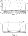
- Fig. 3 illustrates in particular an example embodiment of the wiper blade 302.
- the horizontally extending wiper guide is omitted from Fig. 3 .
- the wiper blade 302 is connected to the horizontally extending wiper guide element at an angle ( ⁇ ) in a vertically downward direction from a center portion of the horizontally extending wiper guide element towards an end portion thereof.
- ⁇ angle in a vertically downward direction from a center portion of the horizontally extending wiper guide element towards an end portion thereof.
- Fig. 4 is a top view of the wiper system 100 according to an example embodiment.
- the horizontal wiper arrangement 300 comprises the wiper blade 302 and the horizontally extending wiper guide element 304 connected to the wiper blade 302. The following will mainly focus on the interconnection between the horizontally extending wiper guide element 304 and the wiper blade 302.
- the wiper system 100 comprises a plurality of spring elements 700 arranged between the wiper blade 302 and the horizontally extending wiper guide element 304.
- the plurality of spring elements 700 are spaced apart from each other.
- the plurality of spring elements 700 are uniformly spaced apart from each other.
- the plurality of spring elements 700 are thus arranged to push the wiper blade 302 towards the surface of the vehicle windshield 102.
- the plurality of spring elements 700 are pre-compressed between the wiper blade 302 and the horizontally extending wiper guide element 304.
- a substantially uniform contact pressure between the wiper blade 302 and the vehicle windshield 102 is achieved over the full length of the wiper blade 302.
- the horizontally extending wiper guide element 304 comprises a horizontal wiper guide rail 310 and a fluid reservoir 312.
- the fluid reservoir 312 comprises a liquid fluid 500 and the fluid reservoir 312 is in fluid communication with the horizontal wiper guide rail 310 for forcing liquid fluid 500 thereto.
- each spring 700 is arranged in connection with the liquid fluid 500 in the horizontal wiper guide rail 310 via a respective piston 314.
- the liquid fluid 500 from the fluid reservoir 312 is directed to the horizontal wiper guide rail 310 where it exposes the respective piston 314 to a fluid pressure forcing the piston 700 and the wiper blade 302 towards the vehicle windshield 102.
- the fluid reservoir 312 comprises a cylinder 320 housing the liquid fluid 500.
- the fluid reservoir 312 comprises a reservoir piston 322.
- the reservoir piston 322 is arranged to force the fluid from the fluid reservoir 312 to the horizontal wiper guide rail 310.
- the reservoir piston 322 is preferably, by its dead weight and the gravitational force, pushing the liquid fluid towards the horizontal wiper guide rail 310.
- a diameter of the fluid reservoir 312 is larger than a diameter of the horizontal wiper guide rail.
- the fluid reservoir 312 is filled with fluid and the reservoir piston 322 is placed above the fluid.
- the gravitational force pulls down the reservoir piston 322 at substantially all times, exerting force on the fluid in the channels, i.e. in the horizontal wiper guide rail 310.
- the force is then transferred to the springs 700 via the pistons 314, which ensures that the wiper blade 302 will always be in constant contact with the vehicle windshield 102.
- the reservoir piston 322 will supply the required fluid into the chamber of that particular spring 700 and force the wiper blade, at this position, towards the vehicle windshield 102.
- excess fluid can be transferred back to the fluid reservoir 312, or any chamber where the force on the particular piston 314 is relatively low.
- the wiper blade can be ensured to sufficiently touch the vehicle windshield 102.
- the reservoir piston 322 is designed to float on the liquid fluid 500 in the fluid reservoir 312.
- Fig. 6 is a side view of the wiper system according to a still further example embodiment.
- the embodiment in Fig. 6 is in many ways similar to the embodiment depicted in Fig. 4 and described above, although the Fig. 6 embodiment can be combined with the embodiment depicted in Fig. 5 as well.
- the wiper system comprises a transparent magnetic coating 340.
- the magnetic coating 340 is attached to the surface of the vehicle windshield 302, preferably on the inside facing the interior of the vehicle cabin.
- the plurality of spring elements 700 comprises a metal of magnetic material.
- the springs 700 will be forced towards the vehicle windshield as a result of magnetism.
Landscapes
- Engineering & Computer Science (AREA)
- Mechanical Engineering (AREA)
- Body Structure For Vehicles (AREA)
- Transmission Devices (AREA)
Claims (13)
- Système d'essuie-glace (100) pour pare-brise de véhicule (102), ce système d'essuie-glace comprenant- un premier bras d'essuie-glace (104) et un second bras d'essuie-glace (106), les premier et second bras d'essuie-glace étant mobiles dans au moins un sens vertical (200) ; et- un dispositif d'essuie-glace horizontal (300) comprenant une lame d'essuie-glace (302) conçue pour essuyer la surface du pare-brise de véhicule, le dispositif d'essuie-glace horizontal (300) comprenant en outre un élément de guidage d'essuie-glace s'étendant horizontalement (304) connecté à la lame d'essuie-glace pour disposer la lame d'essuie-glace de manière à ce qu'elle s'étende entre des faces terminales verticales (502, 504) du pare-brise de véhicule, les premier (104) et second (106) bras d'essuie-glace étant connectés à l'élément de guidage d'essuie-glace s'étendant horizontalement (304) pour déplacer verticalement le dispositif d'essuie-glace horizontal (300) entre une position verticalement basse (602) du pare-brise de véhicule et une position verticalement haute (604) du pare-brise de véhicule ;caractérisé en ce que le système d'essuie-glace (100) comprend en outre une pluralité d'éléments à ressort (700) connectant la lame d'essuie-glace (302) à l'élément de guidage d'essuie-glace s'étendant horizontalement (304), la pluralité d'éléments à ressort étant espacés les uns des autres sur la longueur de l'élément de guidage d'essuie-glace s'étendant horizontalement (304), les éléments à ressort (700) étant conçus pour pousser la lame d'essuie-glace (302) vers le pare-brise dans un sens horizontal (202) perpendiculairement à la direction de l'élément de guidage d'essuie-glace s'étendant horizontalement, la lame d'essuie-glace (302) étant connectée à l'élément de guidage d'essuie-glace s'étendant horizontalement (304) suivant un angle (α) dans un sens verticalement descendant depuis une position centrale de l'élément de guidage d'essuie-glace s'étendant horizontalement vers sa section terminale.
- Système d'essuie-glace selon la revendication 1, dans lequel la pluralité d'éléments à ressort sont espacés uniformément les uns des autres.
- Système d'essuie-glace selon l'une quelconque des revendications 1 ou 2, dans lequel chacun des premier (104) et second (106) bras d'essuie-glace est connecté de manière à pouvoir pivoter à l'élément de guidage d'essuie-glace s'étendant horizontalement (304) pour rotation autour d'un axe de rotation géométrique configuré pour être sensiblement perpendiculaire à un plan défini par la surface du pare-brise.
- Système d'essuie-glace selon l'une quelconque des revendications précédentes, dans lequel chacun des premier (104) et second (106) bras d'essuie-glace comprend une section pivotable (105, 107) à une extrémité opposée comparativement à la connexion de l'élément de guidage d'essuie-glace s'étendant horizontalement (304), les premier et second bras d'essuie-glace étant connectables de manière à pouvoir tourner à une section du châssis du véhicule.
- Système d'essuie-glace selon l'une quelconque des revendications précédentes, dans lequel chacun des premier et second bras d'essuie-glace comprend une section rétractable (109, 111) pour étendre et rétracter les premier (104) et second (106) bras d'essuie-glace lors du déplacement vertical du dispositif d'essuie-glace horizontal (300) entre les positions verticalement basse et haute du pare-brise de véhicule.
- Système d'essuie-glace selon l'une quelconque des revendications précédentes, comprenant en outre une section coulissante horizontale (113), une des sections terminales de chacun des premier et second bras d'essuie-glace étant connectée de manière à pouvoir coulisser à la section coulissante horizontale pour être mobile horizontalement lors du déplacement vertical du dispositif d'essuie-glace horizontal entre les positions verticalement basse et haute du pare-brise de véhicule.
- Système d'essuie-glace selon l'une quelconque des revendications précédentes, comprenant en outre un moteur électrique (120) connecté à chacun des premier (104) et second (106) bras d'essuie-glace pour commander le mouvement vertical du dispositif d'essuieglace horizontal (300).
- Système d'essuie-glace selon l'une quelconque des revendications précédentes, dans lequel les premier (104) et second (106) bras d'essuie-glace comprennent une lame d'essuie-glace respective (121, 123) conçue pour glisser contre la surface du pare-brise de véhicule lors du déplacement vertical du dispositif d'essuieglace horizontal entre les positions verticalement basse et haute du pare-brise de véhicule.
- Système d'essuie-glace selon l'une quelconque des revendications précédentes, dans lequel l'élément de guidage d'essuie-glace s'étendant horizontalement (304) comprend un rail de guidage d'essuie-glace horizontal (310) et un réservoir à fluide (312) en communication fluidique avec le rail de guidage d'essuie-glace horizontal (310), chaque élément à ressort (700) étant connecté à un piston (314) du rail de guidage d'essuieglace horizontal (310), le piston étant exposé à une pression de fluide provenant du fluide dans le réservoir à fluide.
- Système d'essuie-glace selon la revendication 9, dans lequel le réservoir à fluide (312) comprend un cylindre (320) pour abriter le fluide, et un piston de réservoir (322) pour pousser le fluide vers le rail de guidage d'essuie-glace horizontal.
- Système d'essuie-glace selon l'une quelconque des revendications 9 ou 10, dans lequel le réservoir à fluide possède un diamètre supérieur à un diamètre du rail de guidage d'essuie-glace horizontal.
- Système d'essuie-glace selon l'une quelconque des revendications précédentes, dans lequel les éléments à ressort (700) contiennent un métal en matériau magnétique, le système d'essuie-glace (100) comprenant en outre un revêtement magnétique transparent (340) connectable à une surface du pare-brise (102).
- Véhicule (10) comprenant un pare-brise de véhicule (102) et un système d'essuie-glace (100) selon l'une quelconque des revendications précédentes, la lame d'essuie-glace étant disposée en butée avec le pare-brise de véhicule.
Applications Claiming Priority (2)
| Application Number | Priority Date | Filing Date | Title |
|---|---|---|---|
| IN201941010716 | 2019-03-19 | ||
| PCT/EP2020/051967 WO2020187471A1 (fr) | 2019-03-19 | 2020-01-28 | Système d'essuie-glace pour pare-brise de véhicule |
Publications (3)
| Publication Number | Publication Date |
|---|---|
| EP3941789A1 EP3941789A1 (fr) | 2022-01-26 |
| EP3941789B1 true EP3941789B1 (fr) | 2023-08-16 |
| EP3941789C0 EP3941789C0 (fr) | 2023-08-16 |
Family
ID=69326539
Family Applications (1)
| Application Number | Title | Priority Date | Filing Date |
|---|---|---|---|
| EP20702287.2A Active EP3941789B1 (fr) | 2019-03-19 | 2020-01-28 | Système d'essuie-glace pour pare-brise de véhicule |
Country Status (4)
| Country | Link |
|---|---|
| US (1) | US11794700B2 (fr) |
| EP (1) | EP3941789B1 (fr) |
| CN (1) | CN113557181A (fr) |
| WO (1) | WO2020187471A1 (fr) |
Family Cites Families (17)
| Publication number | Priority date | Publication date | Assignee | Title |
|---|---|---|---|---|
| US1515584A (en) * | 1921-03-03 | 1924-11-11 | Hansen Windshield Cleaner Co I | Windshield-cleaning device |
| GB515378A (en) * | 1938-05-30 | 1939-12-04 | Trico Folberth Ltd | Improvements in or relating to windscreen wipers |
| US3089175A (en) * | 1960-09-01 | 1963-05-14 | Hamilton Clamp & Stampings Ltd | Windshield wipers |
| FR2551709B1 (fr) * | 1983-09-13 | 1987-06-12 | Champion Spark Plug Europ | Systeme d'essuie-glace pour vehicules a moteur |
| AT395135B (de) * | 1990-10-04 | 1992-09-25 | Battlogg Stefan Ing | Scheibenwischeranlage |
| DE4139457A1 (de) | 1991-11-29 | 1993-06-03 | Franz D Amandi | Wischvorrichtung fuer scheiben von kraftfahrzeugen |
| US5179758A (en) * | 1991-12-04 | 1993-01-19 | Smith Darrel L | Wiper attachment for rear view mirrors |
| DE4333137C2 (de) | 1993-09-29 | 1996-01-04 | Daimler Benz Ag | Scheibenwischeinrichtung |
| EP0918672A1 (fr) * | 1996-07-10 | 1999-06-02 | Sridhar Kota | Systeme repartiteur de forces flexible pour essuie-glaces |
| KR20020055979A (ko) | 2000-12-29 | 2002-07-10 | 이계안 | 자동차용 와이퍼 시스템 |
| JP2003034238A (ja) * | 2001-05-15 | 2003-02-04 | Honda Motor Co Ltd | ワイパ装置 |
| FR2954250B1 (fr) * | 2009-12-21 | 2014-07-04 | Airbus Operations Sas | Balai d'essuie-glace a flexibilite verticale modifiable |
| US8365345B1 (en) * | 2011-08-24 | 2013-02-05 | Nathan Bush | Windshield wiper lifter |
| JP5808625B2 (ja) * | 2011-09-13 | 2015-11-10 | 株式会社ミツバ | ワイパ装置 |
| FR2994915B1 (fr) | 2012-09-05 | 2015-07-17 | Peugeot Citroen Automobiles Sa | Systeme d'essuyage d'un panneau vitre et becquet comportant un tel systeme |
| CN104670167B (zh) * | 2015-02-13 | 2016-09-14 | 北京理工大学 | 一种全覆盖风挡玻璃的雨刷器 |
| US10124771B2 (en) * | 2016-01-29 | 2018-11-13 | Takao Tsuruta | Wiper system |
-
2020
- 2020-01-28 EP EP20702287.2A patent/EP3941789B1/fr active Active
- 2020-01-28 WO PCT/EP2020/051967 patent/WO2020187471A1/fr unknown
- 2020-01-28 US US17/439,051 patent/US11794700B2/en active Active
- 2020-01-28 CN CN202080019734.8A patent/CN113557181A/zh active Pending
Also Published As
| Publication number | Publication date |
|---|---|
| EP3941789A1 (fr) | 2022-01-26 |
| US20220153233A1 (en) | 2022-05-19 |
| CN113557181A (zh) | 2021-10-26 |
| EP3941789C0 (fr) | 2023-08-16 |
| WO2020187471A1 (fr) | 2020-09-24 |
| US11794700B2 (en) | 2023-10-24 |
Similar Documents
| Publication | Publication Date | Title |
|---|---|---|
| CN204870916U (zh) | 挡风玻璃雨刷组件 | |
| US20190009750A1 (en) | A vehicle wiper unit | |
| KR20190005776A (ko) | 차량용 와이퍼 시스템 | |
| EP3941789B1 (fr) | Système d'essuie-glace pour pare-brise de véhicule | |
| CA1257952A (fr) | Entrainement d'essuie-glace | |
| CN112313144B (zh) | 具有多个四杆运动联动装置的主动式空气动力学提升门扰流板设计 | |
| CN110678364B (zh) | 用于交通工具的减小弧的风挡刮水器系统 | |
| US11511704B2 (en) | Windshield wiper system and vehicle comprising this system | |
| CN111547010A (zh) | 可延伸的挡风玻璃雨刮器系统 | |
| CN106985790B (zh) | 一种装配雨刮系统的汽车 | |
| US6751825B2 (en) | Wiper for multiple and independent surfaces | |
| KR20080074454A (ko) | 자동차용 와이퍼 장치 | |
| CN104411549A (zh) | 挡风玻璃刮水装置 | |
| CN104395155B (zh) | 挡风玻璃刮水器臂 | |
| CN109318860B (zh) | 驾驶室及工程车辆 | |
| KR101401702B1 (ko) | 차량용 와이퍼 장치 | |
| CN105292063A (zh) | 新型汽车雨刮器 | |
| US3003172A (en) | Windshield wiper mechanism | |
| JP2012020625A (ja) | 自動車のワイパ | |
| JP7445857B2 (ja) | 被拭面回転移動式ワイパー機構 | |
| KR20160103433A (ko) | 차량용 와이퍼 장치 | |
| CN112061031A (zh) | 后视镜总成及车辆 | |
| US3775803A (en) | Headlamp cleaner arrangements | |
| KR100600114B1 (ko) | 유성기어장치를 이용한 차량용 와이퍼 장치 | |
| WO2014062404A1 (fr) | Ensemble bras d'essuie-glace de lunette arrière ayant une position d'encliquetage de service vers le haut |
Legal Events
| Date | Code | Title | Description |
|---|---|---|---|
| STAA | Information on the status of an ep patent application or granted ep patent |
Free format text: STATUS: UNKNOWN |
|
| STAA | Information on the status of an ep patent application or granted ep patent |
Free format text: STATUS: THE INTERNATIONAL PUBLICATION HAS BEEN MADE |
|
| PUAI | Public reference made under article 153(3) epc to a published international application that has entered the european phase |
Free format text: ORIGINAL CODE: 0009012 |
|
| STAA | Information on the status of an ep patent application or granted ep patent |
Free format text: STATUS: REQUEST FOR EXAMINATION WAS MADE |
|
| 17P | Request for examination filed |
Effective date: 20210917 |
|
| AK | Designated contracting states |
Kind code of ref document: A1 Designated state(s): AL AT BE BG CH CY CZ DE DK EE ES FI FR GB GR HR HU IE IS IT LI LT LU LV MC MK MT NL NO PL PT RO RS SE SI SK SM TR |
|
| DAV | Request for validation of the european patent (deleted) | ||
| DAX | Request for extension of the european patent (deleted) | ||
| GRAP | Despatch of communication of intention to grant a patent |
Free format text: ORIGINAL CODE: EPIDOSNIGR1 |
|
| STAA | Information on the status of an ep patent application or granted ep patent |
Free format text: STATUS: GRANT OF PATENT IS INTENDED |
|
| INTG | Intention to grant announced |
Effective date: 20230315 |
|
| GRAS | Grant fee paid |
Free format text: ORIGINAL CODE: EPIDOSNIGR3 |
|
| GRAA | (expected) grant |
Free format text: ORIGINAL CODE: 0009210 |
|
| STAA | Information on the status of an ep patent application or granted ep patent |
Free format text: STATUS: THE PATENT HAS BEEN GRANTED |
|
| AK | Designated contracting states |
Kind code of ref document: B1 Designated state(s): AL AT BE BG CH CY CZ DE DK EE ES FI FR GB GR HR HU IE IS IT LI LT LU LV MC MK MT NL NO PL PT RO RS SE SI SK SM TR |
|
| REG | Reference to a national code |
Ref country code: CH Ref legal event code: EP |
|
| REG | Reference to a national code |
Ref country code: DE Ref legal event code: R096 Ref document number: 602020015818 Country of ref document: DE |
|
| REG | Reference to a national code |
Ref country code: IE Ref legal event code: FG4D |
|
| U01 | Request for unitary effect filed |
Effective date: 20230912 |
|
| U07 | Unitary effect registered |
Designated state(s): AT BE BG DE DK EE FI FR IT LT LU LV MT NL PT SE SI Effective date: 20230915 |
|
| PG25 | Lapsed in a contracting state [announced via postgrant information from national office to epo] |
Ref country code: GR Free format text: LAPSE BECAUSE OF FAILURE TO SUBMIT A TRANSLATION OF THE DESCRIPTION OR TO PAY THE FEE WITHIN THE PRESCRIBED TIME-LIMIT Effective date: 20231117 |
|
| PG25 | Lapsed in a contracting state [announced via postgrant information from national office to epo] |
Ref country code: IS Free format text: LAPSE BECAUSE OF FAILURE TO SUBMIT A TRANSLATION OF THE DESCRIPTION OR TO PAY THE FEE WITHIN THE PRESCRIBED TIME-LIMIT Effective date: 20231216 |
|
| PG25 | Lapsed in a contracting state [announced via postgrant information from national office to epo] |
Ref country code: RS Free format text: LAPSE BECAUSE OF FAILURE TO SUBMIT A TRANSLATION OF THE DESCRIPTION OR TO PAY THE FEE WITHIN THE PRESCRIBED TIME-LIMIT Effective date: 20230816 Ref country code: NO Free format text: LAPSE BECAUSE OF FAILURE TO SUBMIT A TRANSLATION OF THE DESCRIPTION OR TO PAY THE FEE WITHIN THE PRESCRIBED TIME-LIMIT Effective date: 20231116 Ref country code: IS Free format text: LAPSE BECAUSE OF FAILURE TO SUBMIT A TRANSLATION OF THE DESCRIPTION OR TO PAY THE FEE WITHIN THE PRESCRIBED TIME-LIMIT Effective date: 20231216 Ref country code: HR Free format text: LAPSE BECAUSE OF FAILURE TO SUBMIT A TRANSLATION OF THE DESCRIPTION OR TO PAY THE FEE WITHIN THE PRESCRIBED TIME-LIMIT Effective date: 20230816 Ref country code: GR Free format text: LAPSE BECAUSE OF FAILURE TO SUBMIT A TRANSLATION OF THE DESCRIPTION OR TO PAY THE FEE WITHIN THE PRESCRIBED TIME-LIMIT Effective date: 20231117 |
|
| U20 | Renewal fee paid [unitary effect] |
Year of fee payment: 5 Effective date: 20240125 |
|
| PG25 | Lapsed in a contracting state [announced via postgrant information from national office to epo] |
Ref country code: PL Free format text: LAPSE BECAUSE OF FAILURE TO SUBMIT A TRANSLATION OF THE DESCRIPTION OR TO PAY THE FEE WITHIN THE PRESCRIBED TIME-LIMIT Effective date: 20230816 |
|
| PG25 | Lapsed in a contracting state [announced via postgrant information from national office to epo] |
Ref country code: ES Free format text: LAPSE BECAUSE OF FAILURE TO SUBMIT A TRANSLATION OF THE DESCRIPTION OR TO PAY THE FEE WITHIN THE PRESCRIBED TIME-LIMIT Effective date: 20230816 |
|
| PG25 | Lapsed in a contracting state [announced via postgrant information from national office to epo] |
Ref country code: SM Free format text: LAPSE BECAUSE OF FAILURE TO SUBMIT A TRANSLATION OF THE DESCRIPTION OR TO PAY THE FEE WITHIN THE PRESCRIBED TIME-LIMIT Effective date: 20230816 Ref country code: RO Free format text: LAPSE BECAUSE OF FAILURE TO SUBMIT A TRANSLATION OF THE DESCRIPTION OR TO PAY THE FEE WITHIN THE PRESCRIBED TIME-LIMIT Effective date: 20230816 Ref country code: ES Free format text: LAPSE BECAUSE OF FAILURE TO SUBMIT A TRANSLATION OF THE DESCRIPTION OR TO PAY THE FEE WITHIN THE PRESCRIBED TIME-LIMIT Effective date: 20230816 Ref country code: CZ Free format text: LAPSE BECAUSE OF FAILURE TO SUBMIT A TRANSLATION OF THE DESCRIPTION OR TO PAY THE FEE WITHIN THE PRESCRIBED TIME-LIMIT Effective date: 20230816 Ref country code: SK Free format text: LAPSE BECAUSE OF FAILURE TO SUBMIT A TRANSLATION OF THE DESCRIPTION OR TO PAY THE FEE WITHIN THE PRESCRIBED TIME-LIMIT Effective date: 20230816 |