EP3937836B1 - Montageschnittstelle zwischen einer suprakonstruktion und einem implantatkörper - Google Patents
Montageschnittstelle zwischen einer suprakonstruktion und einem implantatkörper Download PDFInfo
- Publication number
- EP3937836B1 EP3937836B1 EP20718130.6A EP20718130A EP3937836B1 EP 3937836 B1 EP3937836 B1 EP 3937836B1 EP 20718130 A EP20718130 A EP 20718130A EP 3937836 B1 EP3937836 B1 EP 3937836B1
- Authority
- EP
- European Patent Office
- Prior art keywords
- thread
- threads
- screw bolt
- drive
- external
- Prior art date
- Legal status (The legal status is an assumption and is not a legal conclusion. Google has not performed a legal analysis and makes no representation as to the accuracy of the status listed.)
- Active
Links
Images


Classifications
-
- A—HUMAN NECESSITIES
- A61—MEDICAL OR VETERINARY SCIENCE; HYGIENE
- A61C—DENTISTRY; APPARATUS OR METHODS FOR ORAL OR DENTAL HYGIENE
- A61C8/00—Means to be fixed to the jaw-bone for consolidating natural teeth or for fixing dental prostheses thereon; Dental implants; Implanting tools
- A61C8/0048—Connecting the upper structure to the implant, e.g. bridging bars
- A61C8/005—Connecting devices for joining an upper structure with an implant member, e.g. spacers
-
- A—HUMAN NECESSITIES
- A61—MEDICAL OR VETERINARY SCIENCE; HYGIENE
- A61C—DENTISTRY; APPARATUS OR METHODS FOR ORAL OR DENTAL HYGIENE
- A61C8/00—Means to be fixed to the jaw-bone for consolidating natural teeth or for fixing dental prostheses thereon; Dental implants; Implanting tools
- A61C8/0048—Connecting the upper structure to the implant, e.g. bridging bars
- A61C8/005—Connecting devices for joining an upper structure with an implant member, e.g. spacers
- A61C8/006—Connecting devices for joining an upper structure with an implant member, e.g. spacers with polygonal positional means, e.g. hexagonal or octagonal
-
- A—HUMAN NECESSITIES
- A61—MEDICAL OR VETERINARY SCIENCE; HYGIENE
- A61C—DENTISTRY; APPARATUS OR METHODS FOR ORAL OR DENTAL HYGIENE
- A61C8/00—Means to be fixed to the jaw-bone for consolidating natural teeth or for fixing dental prostheses thereon; Dental implants; Implanting tools
- A61C8/0048—Connecting the upper structure to the implant, e.g. bridging bars
- A61C8/005—Connecting devices for joining an upper structure with an implant member, e.g. spacers
- A61C8/0068—Connecting devices for joining an upper structure with an implant member, e.g. spacers with an additional screw
-
- A—HUMAN NECESSITIES
- A61—MEDICAL OR VETERINARY SCIENCE; HYGIENE
- A61C—DENTISTRY; APPARATUS OR METHODS FOR ORAL OR DENTAL HYGIENE
- A61C8/00—Means to be fixed to the jaw-bone for consolidating natural teeth or for fixing dental prostheses thereon; Dental implants; Implanting tools
- A61C8/0048—Connecting the upper structure to the implant, e.g. bridging bars
- A61C8/005—Connecting devices for joining an upper structure with an implant member, e.g. spacers
- A61C8/0069—Connecting devices for joining an upper structure with an implant member, e.g. spacers tapered or conical connection
-
- A—HUMAN NECESSITIES
- A61—MEDICAL OR VETERINARY SCIENCE; HYGIENE
- A61C—DENTISTRY; APPARATUS OR METHODS FOR ORAL OR DENTAL HYGIENE
- A61C8/00—Means to be fixed to the jaw-bone for consolidating natural teeth or for fixing dental prostheses thereon; Dental implants; Implanting tools
- A61C8/0018—Means to be fixed to the jaw-bone for consolidating natural teeth or for fixing dental prostheses thereon; Dental implants; Implanting tools characterised by the shape
- A61C8/0022—Self-screwing
-
- A—HUMAN NECESSITIES
- A61—MEDICAL OR VETERINARY SCIENCE; HYGIENE
- A61C—DENTISTRY; APPARATUS OR METHODS FOR ORAL OR DENTAL HYGIENE
- A61C8/00—Means to be fixed to the jaw-bone for consolidating natural teeth or for fixing dental prostheses thereon; Dental implants; Implanting tools
- A61C8/0018—Means to be fixed to the jaw-bone for consolidating natural teeth or for fixing dental prostheses thereon; Dental implants; Implanting tools characterised by the shape
- A61C8/0036—Tooth replica
Definitions
- the invention relates to a mounting interface between a superstructure support bearing a superstructure—having a continuous, bent recess—and an implant body having an internal thread, with the aid of a screw bolt.
- the superstructure support and the implant body have a coupling geometry that is at least partially complementary to ensure the anti-rotational stability of the mounting interface.
- the recess of the superstructure support is open toward the superstructure and the implant body.
- a dental implant in which a superstructure support is secured to an implant body with a screw connection.
- the screw connection is realized with a threaded bolt.
- An endosseous implant body is used to support the prosthesis.
- the implant body a type of screw anchor, is screwed into a hole artificially created in the patient's jaw.
- the screwed-in implant body accommodates an implant post in the finished prosthesis.
- the implant post is secured to the implant body with a special clamping device to prevent rotation.
- a superstructure forming the visible tooth crown is attached directly or indirectly to the implant post, e.g., by bonding.
- a dental implant build-up system is known in which an implant body, a superstructure carrier, an adhesive body and an artificial crown form an artificial tooth replacement.
- the present invention is based on the problem of improving an assembly interface between a superstructure support and an implant body in such a way that a secure support of the superstructure is ensured with simple pre- and final assembly.
- An internal drive thread is arranged in the recess of the superstructure support in the area facing the implant body.
- the screw bolt has two external threads arranged one behind the other with or without a gap, the first of which is an external drive thread and the second an external clamping thread. Both external threads have different pitches.
- the external drive thread fits into the internal drive thread of the recess of the superstructure support, while the external clamping thread fits into the internal clamping thread of the implant body.
- the screw bolt has an intermediate section between the external clamping thread and the external drive thread.
- This is either composed of a cylindrical pin and a stop flange that can be placed against a flat stop collar, with the stop collar forming a transition between the internal drive thread and a cylindrical bore in the recess, or the intermediate section is designed without a stop collar, with a cylindrical undercut bore adjoining the internal drive thread, which merges into a stop zone in the form of a constriction that widens towards the undercut bore, so that the screw bolt can be screwed far enough from the internal drive thread into the superstructure support before the superstructure support is attached to the implant body that its external drive thread leaves the internal drive thread again to enter the undercut bore, and a threadless cylindrical pin of the screw bolt fits through the constriction with little play.
- the invention provides an assembly interface that connects a superstructure support to an implant body using a double-screw drive.
- both the superstructure support and the implant body each have their own internal thread. Both internal threads mesh with two different external threads of a screw bolt.
- the screw bolt is securely positioned in the internal thread at the lower end of the superstructure support by screwing it in or through.
- the superstructure support is inserted together with the screw bolt into the The implant body is inserted.
- the free end of the screw bolt is positioned in front of the internal thread of the implant body.
- the screw bolt is set in a rotational movement so that, on the one hand, the front screw bolt thread screws into the implant body thread and, on the other hand, the superstructure support and the implant body move translationally toward each other.
- the screw bolt thus permanently clamps the superstructure support and the implant body against each other.
- the threads connecting the three parts involved in the assembly interface are single-start and/or multi-start.
- the radial outer contour of the screw bolt does not have a tool engagement surface for screwing or unscrewing it into or out of the implant body.
- This restriction does not affect the radial contour of an axial bore or other axial recess.
- the bolt which unlike a regular screw does not have a screw head, does not need to be inserted through the opening in the superstructure body into the recess closest to the superstructure. Consequently, this recess can have a cross-section along its entire length that is smaller than the cross-section of a regular screw head. Thus, using this mounting interface without changing the size of the superstructure beam increases its rigidity.
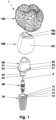
- the Figure 1 shows an example of all the parts of an artificial tooth (1) in the form of an exploded view.
- a hollow screw-like implant body (10) serves as the basis.
- a superstructure support (20), in combination with, for example, an adhesive body (100), is securely positioned and screwed into place using a special screw bolt (60).
- the angled superstructure support (20) sits in a conical seat (14) in the implant body (10).
- the superstructure support (20) is held in a recess (13) of the implant body (10) by means of the screw bolt (60).
- An artificial tooth crown (120) is usually placed and bonded to the adhesive body (100) as a further superstructure component.
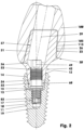
- the basis of the prosthetic denture (1) is an implant body (10) that can be screwed into the jawbone. It is a hollow screw with a possibly self-tapping, e.g., non-metric external thread. Approximately in the upper half, the implant body (10) has a multi-level recess (13), which is divided into three zones (see figure). Figure 2
- the first zone (14), located in the area of the implant shoulder (12) of the implant body (10), is an internal cone with a cone angle of, for example, 18 degrees.
- the internal cone (14) transitions into a hexagon socket (15) in the second zone, which serves as an anti-twist device.
- the third zone (17) is a threaded hole with an internal clamping thread (82), which, during assembly, accommodates the screw bolt (60) holding the superstructure support (20).
- the right-hand internal clamping thread (82) is, for example, an M 1.6 ⁇ 0.35 thread according to DIN 13, Sheet 1.
- the superstructure support (20) primarily serves the purpose of serving as a base for the artificial tooth crown (120) while seated within the implant body (10). It has a region facing the implant body (10) and a region facing the tooth crown (120) or the superstructure.
- the area facing the implant body (10) is the implant neck (42) with its outer cone (43) and its external hexagon (44).
- the outer cone (43) and the external hexagon (44) fit precisely in the recess (13) of the implant body (10).
- the end faces of the external hexagon (44) do not contact the recess (13).
- the implant neck (42) is an implant plate (31), which, for example, emerges from the implant neck (42) with a continuous transition.
- the non-circular implant plate (31) has, at least in part or in part, the shape of the shell of a truncated cone, the cone angle of which opens towards the tooth crown (120).
- the cone angle is, for example, between 125 and 131 degrees.
- the underside of the implant plate (31) may also consist of several conical cones extending from one another, each of which encloses a different angle with respect to the center line (29). In this case, the cone angles are between 120 and 136 degrees.
- the outer edge (33) of the implant plate (31) is positioned at a distance from the centerline (29) that continuously changes between 2.22 and 3.48 mm during a 360° rotation around the centerline (29).
- the edge (33) experiences a height offset of 0.8 ⁇ 0.2 mm in the longitudinal direction of the centerline (29).
- the implant post (23) extends above the implant plate (31).
- the latter has a cross-section in the, for example, rounded transition area to the implant plate (31) that is smaller than the maximum cross-section of the implant plate (31).
- the implant plate (31) also has a flat upper edge (37) towards the implant post (23).
- the contour of the flat upper edge is oriented perpendicular to the center line (29) at least in some areas.
- the implant plate (31) protrudes, for example, 0.4 to 0.5 mm in the radial direction.
- the widest point can measure more than, for example, 2 mm.
- the flat upper edge (37) forms, among other things, a seating surface for the adhesive body (100) or the tooth crown (120).
- the rounded transition area can also be deepened in the axial direction, parallel to the center line (29), by 0.05 to 0.2 mm, so that a groove (35) is created between the flat upper edge surface (37) and the implant post (23).
- Figure 2 In the section shown, the implant post (23) tapers towards the top.
- the implant post (23) consists, in a first approximation, of a superposition of an oblique truncated cone with a circular base cross-section and an oblique truncated cone with an elliptical cross-section that partially penetrates this.
- the center lines of the two truncated cones form a plane in which the minor semi-axes of the elliptical cross-section lie.
- there are fillets whose radii are, for example, between 0.3 and 0.4 mm.
- This special shape of the implant post (23) results in a torsion-proof base for the adhesive body (100) to be supported.
- the superstructure support (20) is coated with a titanium nitride coating, at least above the implant plate (31).
- the coating thickness is, for example, 1 to 4 ⁇ m.
- thin-walled ceramic or copolymer coatings can also be applied there.
- the superstructure support (20) has a continuous recess (51) with a kink in the central area with a kink angle of, for example, 11 ⁇ 4 degrees.
- the finished recess (51) consists of four zones.
- the first (52) and second zones (53) are used to insert the screw bolt (60).
- the first, lower zone (52) is a cylindrical bore with a diameter of 2.1 mm, for example, and a depth of approximately 1.9 mm. Its center line (49) coincides with the center line (29).
- the transition between the internal thread (72) and the bore (52) is formed by a flat stop collar (54).
- the fourth, upper zone (57) is also a cylindrical bore. Its centerline (59) intersects the centerline (29) in the third zone (56), e.g., at an angle of 11 degrees.
- the upper zone (57) serves to insert the tool with which the screw bolt (60) is tightened.
- the third zone (56) represents a transition area, which, e.g., has the surface area of a hemisphere, cf. Figure 2 .
- the bolt (60-62) is usually divided into five sections. These are arranged from front to back. a linkage area (63), a drive area (70), an intermediate area (75), a clamping area (80) and a gripping area (85), cf. Figures 3 , 6 and 9 .
- the articulation area (63) is a cylindrical pin (64) into which a tool recess (65) is machined. It has a length of, for example, 1.5 mm and a diameter of, for example, 1.66 mm. Its central tool recess (65) is Figures 3 , 6 and 9 a hexagon socket (66) with a wrench size of, for example, 1.13 mm, whose usable depth is, for example, 1.05 mm.
- a hexagon socket a hexalobular socket, an internal multi-tooth socket, a Phillips recess, a slot, or the like can also be provided.
- Another drive variant is an external hexalobular socket or external hexagon. The hexalobular or hexagonal shapes may be barrel-rounded in the axial direction.
- the tool recess (65) can be machined into the drive area (70) by shortening or omitting the pin (64), whereby the screw bolt (60-62) is shortened by e.g. 1.5 mm or more.
- the drive area (70) has Figures 3 and 6 a fine thread of type M 2 ⁇ 0.25, whose usable length is, for example, 1.73 mm.
- the intermediate area (75) adjoining the drive area (70) serves as a spacer to the subsequent clamping area (80).
- the intermediate area (75), after Figure 2 , sits down consists of a cylindrical pin (76) and a stop flange (78).
- the cylindrical pin (76) has, for example, the same outer diameter as the articulation area (63). If necessary, the outer diameter of the cylindrical pin (76) corresponds to the core diameter of the external drive thread (71).
- the length of the intermediate area (75) is, for example, 1.03 mm.
- a disc-shaped stop flange (78) adjoins the cylinder pin (76) toward the clamping area (80).
- the stop flange (78) has a wall thickness of 0.46 mm and an outer diameter of 2.08 mm, for example.
- the clamping area (80) is represented by an external clamping thread (81). This is a 1.46 mm long M1.6 ⁇ 0.35 standard thread according to DIN 13, Sheet 1.
- the gripping area (85) adjacent to the clamping area (80) has, on the one hand, a geometric shape via which the screw bolt (60-62) can be gripped using a handling device and inserted into the fourth zone (57) of the recess (51) of the superstructure support (20-22) for screwing in, see Figure 4.
- the gripping area (85) facilitates the insertion of the superstructure support (20-22) with the screw bolt (60) screwed in, see. Figure 5 , into the stepped bore of the implant body (10).
- the gripping area (85) is an external hexagon tapering towards the free end of the screw bolt (60). Two opposite flanks of the external hexagon of this gripping device enclose an angle of, for example, 5 degrees.
- the maximum diameter of the external diameter is smaller than the core diameter of the external clamping thread (81).
- Figure 3 The external hexagon has a wrench width of 0.95 mm.
- the gripping area (85) can also be designed as a short cylindrical pin or cone. If a cone is used, it tapers towards its free end.
- the pin or cone preferably has a maximum outer diameter that is less than or equal to the core diameter of the external clamping thread. If necessary, the gripping area (85) can be omitted.
- the screw bolt (60) is gripped by the handling device at the external clamping thread (81) for insertion and screwing into the superstructure support (20).
- the gripping area (85) can be integrated into the clamping area (80) in the form of a bore or recess, either completely or partially.
- the handling device engages the corresponding bore or recess with a miniature clamping mandrel.
- FIG 4 shows the superstructure support (20) when the screw bolt (60) is inserted into the lower recess (53).
- the articulation area (63) of the screw bolt (60) reaches the area of the internal drive thread (72).
- the external drive thread (71) moves in front of the internal drive thread (72) of the superstructure support (20).
- the screw bolt (60) is screwed into the internal drive thread (72) until the stop flange (78) of the screw bolt (60) rests against the stop collar (54), see.
- Figure 5 The screw bolt (60) is now securely seated in the superstructure support (20) in its rear position. In this form, the combination of the superstructure support (20) and the screw bolt (60) can be marketed.
- the replacement bolt (260) has, to a first approximation, all the features of a bolt according to DIN 2509.
- a threaded section is located on either side of a smooth shaft (275).
- the front threaded section is the clamping thread (81), while the rear threaded section is the drive thread (71).
- the drive thread (71) has a tool recess in the form of a slot (267), which allows the replacement bolt (260) to be turned, for example, with a slotted screwdriver.
- the clamping thread (81) and the drive thread (71) each have four thread pitches.
- One thread pitch corresponds to a thread tooth that rotates 360 degrees.
- the clamping thread (81) has a pitch of 7 LE, while the drive thread (71) has a pitch of only 5 LE.
- Both the lifting nut (220) and the locking nut (210) each have four threads.
- the thread pitch of the lifting nut (220) corresponds to the thread pitch of the drive thread (71).
- the thread pitch of the locking nut (210) corresponds to that of the clamping thread (81).
- the locking nut (210) has a locking nut stop (212) on its upper end.
- a rotation-preventing bar (215) extends beyond the locking nut stop (212).
- the lifting nut (220) has a lifting nut stop (222) on its lower end, which is opposite the fixed nut stop (212).
- An anti-rotation groove (225) is arranged in its outer wall.
- the anti-rotation rib (215) of the fixed nut (210) projects into the anti-rotation rib (215).
- the anti-rotation rib (215) corresponds to the internal hexagon (15) of the implant body (10).
- the anti-rotation groove (225) is comparable to the external hexagon (44) of the superstructure support (20).
- the Figure 12 shows the assembly consisting of the lifting nut (220) and the replacement screw bolt (260) immediately after insertion into the locking nut (210).
- the anti-rotation groove (225) of the lifting nut (220) engages the anti-rotation web (215) of the locking nut (210).
- the foremost flank of the front thread of the external clamping thread (81) comes into contact with the rear flank of the internal clamping thread (82).
- the lifting nut stop (222) assumes its maximum distance of 6 LE from the locking nut stop (212) after contact has been established.
- the replacement bolt (260) is screwed into the locking nut (210) by turning it 360° clockwise, see Figure 13.
- the replacement bolt (260) performs a stroke of 7 units.
- the 360° clockwise rotation of the replacement bolt (260) forces it to unscrew one revolution from the lifting nut (220).
- the replacement bolt (260) thereby releases the lifting nut (220) by 5 units.
- the lifting nut (220) moves - in one clamping stroke - by 2 units toward the locking nut (210), whereby the distance between the lifting nut stop (222) and the locking nut stop (212) reduced by 2 LE to 4 LE.
- U is the number of turns of the replacement screw bolt (260)
- p S is the pitch of the clamping thread (81, 82)
- p A is the pitch of the drive thread (71, 72).
- the distance between the lifting nut stop (222) and the fixed nut stop (212) has been reduced to 2 LE.
- the number of thread turns per thread pair (73, 83) in the schematic diagram shown is only an example to clarify the function. Since both thread pairs (73, 83) hold the same clamping load when the lifting nut (220) is tightened, the number of load-bearing thread turns per thread pair varies only slightly.
- the Figure 6 shows a short screw bolt (61) without a stop flange. Its drive thread (71) and its clamping thread (81) correspond to those of the screw bolt (60) in Figure 3. Between the two threads (71, 81) is a truncated cone pin (77) measuring 0.45 mm in length, which tapers towards the clamping thread (81). Its cone angle is 60 degrees, for example.
- the superstructure support (21) matching this screw bolt (61), cf. Figures 7 and 8 has a recess in the superstructure support (21) facing Figure 2 differently designed recess (51).
- the first lower zone (52) is, for example, a right-hand M 2 ⁇ 0.25 internal drive thread (72) according to DIN 13, Sheet 2.
- This fine thread has a length of, for example, 1.33 mm. Its core diameter is, for example, 1.76 mm.
- Adjoining the internal drive thread (72) is a second zone (53), a cylindrical undercut bore (58), whose diameter is, for example, 2.02 mm at a depth of approximately 1.25 mm.
- the bore (58) transitions into a stop zone in the form of a constriction (55), which - in longitudinal section - widens with a 0.5 mm radius towards the undercut bore (58).
- the constriction (55) has an inner diameter of, for example, 1.62 mm, allowing the cylindrical pin (64) of the screw bolt (61) to pass through with minimal clearance. Above the constriction (55), the bore widens into a funnel shape, with an opening angle of at least 10 degrees.
- the center lines of the internal drive thread (72), the undercut bore (58), and the constriction (55) coincide with the center line (29).
- the screw bolt (61) is inserted into the superstructure support (21) from below until screwed in so that its external drive thread (71) leaves the internal drive thread (72) again to enter the rear engagement bore (58).
- the external drive thread (71) of the screw bolt (61) sits captively in the rear engagement bore (58) but is still freely rotatable with play.
- the Figure 8 shows the assembly interface after attaching the superstructure support (21) to the implant body (10).
- the two external threads (71, 81) meshed with their corresponding internal threads (72, 82) almost simultaneously during the screwing-in process.
- the cylindrical pin (64) of the screw bolt (61) closes the constriction (55) with minimal play, so that neither cement nor adhesive can enter the area of the drive thread (71, 72) during further completion of the prosthetic single-tooth replacement.
- FIGS 9-11 show a mounting interface with a replacement screw bolt (262) that has both a right-hand (81) and a left-hand thread (71).
- Figures 16-19 A simplified representation of the double-screw drive in a half-side partial section in four positions.
- the replacement screw bolt (262) has a right-hand clamping thread (81) with four thread turns at the front and a left-hand drive thread (71) with seven thread turns at the rear.
- the mathematical value of both thread pitches is, for example, for both thread pairs (73, 83). identical.
- the replacement screw bolt (262) is shown in the side view.
- the lifting nut (220) is in the Figures 16-19 against the locking nut (210).
- the locking device (215, 225), the lifting nut stop (222) and the locking nut stop (212) are almost identical to the Figures 12-15 taken from the variant shown.
- the replacement bolt (262) is screwed in deeper by one clockwise turn. After the third full turn, the lifting nut stop contacts (222) the locking nut stop (212). The replacement screw bolt (262) is seated with three threads in the locking nut (210) and in the lifting nut (220).
- each thread pair (73, 83) has the same or almost the same number of load-bearing threads.
- a screw bolt (62) is used, which uses an M 1.8 ⁇ 0.2 LH thread as the external drive thread (71).
- the external clamping thread (81) is an M 1.6 ⁇ 0.35 standard thread.
- the intermediate area (75) between the two threads is a cylindrical pin (76), whose diameter corresponds to the core diameter of the external clamping thread (81). The diameter can also be increased to the head diameter of the external drive thread (71).
- the gripping section (85) has Figure 9 the shape of a cylinder.
- the Figure 10 shows the superstructure support (22) together with the screw bolt (62) being inserted into the implant body (10).
- a plastic stop bolt (48) is inserted into the upper part of the recess (51) of the superstructure support (22) in a force-locking manner (for example only). This stop bolt limits the screw-in stroke of the screw bolt (62) when screwing it into the counterclockwise external drive thread (71).
- the stop bolt (48) is removed before inserting the superstructure support (22) into the implanted implant body (10) to make room for the tool.
- All threads shown in the examples are metric threads according to DIN 13. Instead of metric threads, trapezoidal threads, flat threads, buttress threads, round or milk threads, pipe threads, Whitworth threads, UNF/UNC threads, or similar can also be used. All screw bolts (60-62) are made of TiAL6V4 or TiAl6V4 ELI, for example.
- an adhesive body (100) is glued or cemented on.
- the adhesive body (100) is a hollow body arranged within the dental prosthesis between the superstructure support (20) and the artificial tooth crown (120). With its help, among other things, the angular position of the tooth crown (120) is adjusted to the angular position of the implant post (23).
- the adhesive body (100) is essentially cup-shaped. Its inner wall (105) is adapted to the outer wall (26) of the implant post (23), including the upper edge (37).
- the clearance is, for example, 30 to 50 ⁇ m, so that the adhesive body (100) rests on the implant post (23) of the superstructure support (20) over a large area, with an adhesive (113) interposed between it.
- the adhesive body (100) has a lower edge, which supports it against the upper edge (37) of the superstructure support (20). In the area of its upper side (102), it has a recess (106), which, when the prosthesis is mounted, represents an extension of the upper part of the recess (51) of the implant post (23).
- the tooth crown (120) sits on an adhesive body (100). Accordingly, the inner wall of the tooth crown (120) is adapted to the outer wall (101) of the adhesive body (100).
- the clearance between the outer wall (101) and the inner wall of the tooth crown (120) is, for example, 30 to 50 ⁇ m.
- the superstructure support (20) is secured by an implant cone (43) and screwed into the conical seat (14) of the implant body (10).
- the implant neck (42) and the underside of the implant plate (31) rest against the gum.
Landscapes
- Health & Medical Sciences (AREA)
- Oral & Maxillofacial Surgery (AREA)
- Orthopedic Medicine & Surgery (AREA)
- Dentistry (AREA)
- Epidemiology (AREA)
- Life Sciences & Earth Sciences (AREA)
- Animal Behavior & Ethology (AREA)
- General Health & Medical Sciences (AREA)
- Public Health (AREA)
- Veterinary Medicine (AREA)
- Dental Prosthetics (AREA)
- Prostheses (AREA)
Description
- Die Erfindung betrifft eine Montageschnittstelle zwischen einem eine Suprakonstruktion tragenden - eine durchgehende, geknickte Ausnehmung aufweisenden - Suprastrukturträger und einem ein Innengewinde aufweisenden Implantatkörper unter Zuhilfenahme eines Schraubbolzens, wobei der Suprastrukturträger und der Implantatkörper eine zumindest bereichsweise komplementäre Kupplungsgeometrie zur Sicherung der Verdrehsicherheit der Montageschnittstelle aufweisen. Dabei ist die Ausnehmung des Suprastrukturträgers zur Suprakonstruktion und zum Implantatkörper hin offen.
- Aus der
WO 98/52 488 A1 - In der zahnärztlichen Implantologie wird u.a. im Rahmen der Herstellung eines prothetischen Einzelzahnersatzes häufig ein enossaler Implantatkörper verwendet, der die Prothese trägt. In diesem Fall wird der Implantatkörper, eine Art Schraubdübel, in einer künstlich im Patientenkiefer erzeugten Bohrung eingeschraubt. Der eingeschraubte Implantatkörper nimmt bei der fertigen Prothese einen Implantatpfosten auf. Letzterer wird verdrehsicher im Implantatkörper mit einem speziellen Spannmittel befestigt. Auf den Implantatpfosten wird direkt oder indirekt eine, die sichtbare Zahnkrone bildende Suprastruktur, z.B. durch Verkleben, aufgesetzt.
- Aus der
DE 20 2012 102 746 U1 ist ein Zahnimplantataufbausystem bekannt, bei dem ein Implantatkörper, ein Suprastrukturträger, ein Klebekörper und eine künstliche Krone einen künstlichen Zahnersatz bilden. - Der vorliegenden Erfindung liegt die Problemstellung zugrunde, eine Montageschnittstelle zwischen einem Suprastrukturträger und einem Implantatkörper so zu verbessern, dass bei einfacher Vor- und Endmontage ein sicheres Tragen der Suprastruktur gewährleistet ist.
- Diese Problemstellung wird mit den Merkmalen des Patentanspruchs 1 gelöst. Dabei ist in der Ausnehmung des Suprastrukturträgers in ihrem dem Implantatkörper zugewandten Bereich ein Antriebsinnengewinde angeordnet. Der Schraubbolzen weist zwei mit oder ohne Abstand hintereinander angeordnete Außengewinde auf, von denen das erste ein Antriebsaußengewinde und das zweite ein Spannaußengewinde ist. Beide Außengewinde haben unterschiedliche Steigungen. Das Antriebsaußengewinde passt in das Antriebsinnengewinde der Ausnehmung des Suprastrukturträgers, während das Spannaußengewinde in das Spanninnengewinde des Implantatkörpers passen. Der Schraubbolzen weist zwischen dem Spannaußengewinde und dem Antriebsaußengewinde einen Zwischenbereich auf. Entweder setzt sich dieser aus einem Zylinderzapfen und einem an einen planen Anschlagbund anlegbaren Anschlagflansch zusammen, wobei der Anschlagbund einen Übergang zwischen dem Antriebsinnengewinde und einer zylindrischen Bohrung der Ausnehmung bildet oder der Zwischenbereich ist anschlagbundfrei ausgebildet, wobei sich an das Antriebsinnengewinde eine zylindrische Hintergriffsbohrung anschließt, die in eine Anschlagzone in Form einer sich in Richtung der Hintergriffsbohrung aufweitende Engstelle übergeht, sodass der Schraubbolzen vor dem Befestigen des Suprastrukturträgers am Implantatkörper so weit vom Antriebsinnengewinde aus in den Suprastrukturträger hineinschraubbar ist, dass sein Antriebsaußengewinde das Antriebsinnengewinde wieder verlässt, um in die Hintergriffsbohrung zu gelangen und wobei ein gewindeloser Zylinderzapfen des Schraubbolzens mit geringem Spiel durch die Engstelle hindurchpasst.
- Mit der Erfindung wird eine Montageschnittstelle geschaffen, die einen Suprastrukturträger mithilfe eines Doppelschraubgetriebes mit einem Implantatkörper verbindet. Dazu haben sowohl der Suprastrukturträger als auch der Implantatkörper jeweils ein eigenes Innengewinde. Beide Innengewinde kämmen mit zwei verschiedenen Außengewinden eines Schraubbolzens.
- In einem Vormontageschritt wird der Schraubbolzen in das im unteren Ende des Suprastrukturträgers eingearbeitete Innengewinde durch Hineinschrauben oder Hindurchschrauben verliersicher angeordnet. Zur Verbindung mit dem Implantatkörper wird der Suprastrukturträger zusammen mit dem Schraubbolzen in den Implantatkörper eingesetzt. Dabei gelangt das freie Ende des Schraubbolzens vor das Innengewinde des Implantatkörpers. Mithilfe eines Werkzeugs, das durch eine Ausnehmung des Strukturträgers hindurch in eine Werkzeugausnehmung des Schraubbolzenseingekoppelt wird, wird der Schraubbolzen in eine Rotationsbewegung versetzt, sodass sich zum einen das vordere Schraubbolzengewinde in das Implantatkörpergewinde einschraubt und sich zum anderen der Suprastrukturträger und der Implantatkörper translatorisch aufeinander zu bewegen. Mit dem Schraubbolzen werden somit der Suprastrukturträger und der Implantatkörper gegeneinander dauerhaft verspannt.
- Die Gewinde, die die drei an der Montageschnittstelle beteiligten Teile miteinander verbinden, sind ein- und/oder mehrgängig ausgeführt. Zum ein- oder losschraubenden Rotieren des Schraubbolzens - in den oder aus dem Implantatkörper - weist dessen radiale Außenkontur keine Werkzeugangriffsfläche auf.
- Diese Beschränkung betrifft keine radiale Kontur einer axialen Bohrung oder anders gestalteten axialen Ausnehmung.
- Der Schraubbolzen, der im Gegensatz zu einer regulären Schraube keinen Schraubenkopf aufweist, muss nicht durch die Öffnung des Suprastrukturkörpers in die Ausnehmung der Suprastruktur eingebracht werden, die der Suprakonstruktion am nächstgelegenen ist. Folglich kann diese Ausnehmung entlang ihrer gesamten Länge einen Querschnitt haben, der kleiner ist als der Querschnitt eines regulären Schraubenkopfs. Somit erhöht das Verwenden dieser Montageschnittstelle ohne Änderung der Baugröße des Suprastrukturträgers dessen Formsteifigkeit.
- Weitere Einzelheiten der Erfindung ergeben sich aus den Unteransprüchen und der nachfolgenden Beschreibung schematisch dargestellter Ausführungsformen.
- Figur 1:
- Explosionsmodell eines prothetischen Zahnersatzes;
- Figur 2:
- Längsschnitt durch einen prothetischen Zahnersatz ohne Zahnkrone;
- Figur 3:
- Perspektivische Darstellung des Schraubbolzens;
- Figur 4:
- Längsschnitt durch den Suprastrukturträger beim Einstecken des Schraubbolzens;
- Figur 5:
- wie
Figur 4 , jedoch nach dem Einschrauben des Schraubbolzens; - Figur 6:
- Seitenansicht eines kurzen Schraubbolzens;
- Figur 7:
- Längsschnitt durch Suprastrukturträger und Implantatkörper bei lose einstecktem Schraubbolzen;
- Figur 8:
- wie
Figur 7 , jedoch nach dem Befestigen des Suprastrukturträgers; - Figur 9:
- Perspektivische Darstellung eines Schraubbolzens mit gegenläufigen Außengewinden;
- Figur 10:
- Längsschnitt durch den Suprastrukturträger mit eingeschraubtem Schraubbolzen beim Einsetzen in den Implantatkörper (nicht Teil der Erfindung);
- Figur 11:
- wie
Figur 10 , jedoch nach dem Befestigen des SupraStrukturträgers (nicht Teil der Erfindung); - Figur 12:
- vereinfachte Darstellung des Doppelschraubgetriebes mit zwei Rechtsgewinden in halbseitiger Schnittdarstellung vor dem Eindrehen des Ersatzschraubbolzens;
- Figur 13:
- wie
Figur 12 , jedoch ist der Ersatzschraubbolzen um eine Umdrehung eingeschraubt worden; - Figur 14:
- wie
Figur 13 , jedoch ist der Ersatzschraubbolzen um eine weitere Umdrehung eingeschraubt worden; - Figur 15:
- wie
Figur 14 , jedoch ist der Ersatzschraubbolzen um eine letzte Umdrehung eingeschraubt worden; - Figur 16:
- vereinfachte Darstellung des Doppelschraubgetriebes mit einem Links- und einem Rechtsgewinde in halbseitiger Teilschnittdarstellung vor dem Eindrehen des Ersatzschraubbolzens;
- Figur 17:
- wie
Figur 16 , jedoch ist der Ersatzschraubbolzen um eine Umdrehung eingeschraubt worden; - Figur 18:
- wie
Figur 17 , jedoch ist der Ersatzschraubbolzen um eine weitere Umdrehung eingeschraubt worden; - Figur 19:
- wie
Figur 18 , jedoch ist der Ersatzschraubbolzen um eine letzte Umdrehung eingeschraubt worden. - Die
Figur 1 zeigt beispielhaft alle Teile eines künstlichen Zahnes (1) in Form einer Explosionszeichnung. Als Basis dient ein hohlschraubenartiger Implantatkörper (10). Mit ihm wird ein Suprastrukturträger (20), in Kombination mit einem z.B. aufgeklebten Klebekörper (100), mittels eines speziellen Schraubbolzens (60) verdrehsicher positioniert und verschraubt. - Dazu sitzt der z.B. abgewinkelte Suprastrukturträger (20) im Implantatkörper (10) in einem Konussitz (14). Der Suprastrukturträger (20) wird mit Hilfe des Schraubbolzens (60) in einer Ausnehmung (13) des Implantatkörpers (10) gehalten. Auf den Klebekörper (100) wird als weiteres Suprastrukturteil in der Regel eine künstliche Zahnkrone (120) aufgesetzt und verklebt.
- Die Basis des prothetischen Zahnersatzes (1) ist ein in den Kieferknochen einschraubbarer Implantatkörper (10). Er ist eine Hohlschraube mit einem ggf. selbstschneidenden, z.B. nichtmetrischen Außengewinde. Circa in der oberen Hälfte weist der Implantatkörper (10) die mehrstufige Ausnehmung (13) auf, die in drei Zonen aufgeteilt ist, vgl.
Figur 2 . Die erste Zone (14), sie liegt im Bereich der Implantatschulter (12) des Implantatkörpers (10), ist ein Innenkonus, der einen Kegelwinkel von z.B. 18 Winkelgraden aufweist. Der Innenkonus (14) geht in einen als Verdrehsicherung dienenden Innensechskant (15) der zweiten Zone über. Anstelle des Innensechskants (15), kann als Kupplungsgeometrie z.B. auch ein Doppelinnensechskant oder eine andere form- oder kraftschlüssige Verdrehsicherungsgeometrie verwendet werden. Die dritte Zone (17) ist eine Gewindebohrung mit einem Spanninnengewinde (82), das bei der Montage den den Suprastrukturträger (20) haltenden Schraubbolzen (60) aufnimmt. Das rechtssteigende Spanninnengewinde (82) ist beispielsweise ein M 1,6 × 0,35-Gewinde nach DIN 13, Blatt 1. - Der Suprastrukturträger (20) hat primär die Aufgabe - im Implantatkörper (10) sitzend - als Basis für die künstliche Zahnkrone (120) zu dienen. Er hat einen Bereich, der dem Implantatkörper (10) und einen Bereich, der der Zahnkrone (120) bzw. der Suprastruktur zugewandt ist.
- Der dem Implantatkörper (10) zugewandte Bereich ist der Implantathals (42) mit seinem Außenkonus (43) und seinem Außensechskant (44). Der Außenkonus (43) und der Außensechskant (44) sitzen passgenau in der Ausnehmung (13) des Implantatkörpers (10). In der zur Spitze des Implantatkörpers (10) weisenden axialen Richtung kontaktieren die Stirnflächen des Außensechskants (44) die Ausnehmung (13) nicht.
- Oberhalb des Implantathalses (42) schließt sich ein Implantatteller (31) an, der z.B. mit einem stetigen Übergang aus dem Implantathals (42) hervorgeht. Der z.B. unrunde Implantatteller (31) hat zumindest bereichs- oder abschnittsweise die Form des Mantels eines Kegelstumpfes, dessen Konuswinkel sich zur Zahnkrone (120) hin öffnet. Der Konuswinkel liegt z.B. zwischen 125 und 131 Winkelgraden. Ggf. besteht die Unterseite des Implantattellers (31) auch aus mehreren auseinander hervorgehenden Kegelkoni, wobei jeder gegenüber der Mittellinie (29) einen anderen Winkel einschließt. In diesem Fall liegen die Koniwinkel zwischen 120 und 136 Winkelgraden.
- Der äußere Rand (33) des Implantattellers (31) hat hier einen Abstand zur Mittellinie (29), der sich bei einer 360°-Rotation um die Mittellinie (29) z.B. zwischen 2,22 und 3,48 mm bereichsweise stetig ändert. Der Rand (33) erfährt hierbei in Längsrichtung der Mittellinie (29) einen Höhenversatz von z.B. 0,8 ± 0,2 mm.
- Oberhalb des Implantattellers (31) erstreckt sich der Implantatpfosten (23). Letzterer hat im z.B. ausgerundeten Übergangsbereich zum Implantatteller (31) einen Querschnitt, der kleiner ist als der maximale Querschnitt des Implantattellers (31). Somit hat auch der Implantatteller (31) zum Implantatpfosten (23) hin eine flächige Randoberseite (37). In nahezu jeder durch die Mittellinie (29) gelegten Schnittebene ist die Kontur der flächigen Randoberseite zumindest bereichsweise senkrecht zur Mittellinie (29) orientiert. An der schmalsten Stelle ragt der Implantatteller (31) z.B. 0,4 bis 0,5 mm in Radialrichtung über. Die breiteste Stelle kann mehr als z.B. 2 mm messen. Die flächige Randoberseite (37) bildet u.a. eine Aussitzfläche für den Klebekörper (100) oder die Zahnkrone (120).
- Der ausgerundete Übergangsbereich kann auch in axialer Richtung, parallel zur Mittellinie (29), um 0,05 bis 0,2 mm vertieft werden, so dass zwischen der flächigen Randoberseite (37) und dem Implantatpfosten (23) eine Rinne (35) entsteht. Nach dem in
Figur 2 dargestellten Schnitt verjüngt sich der Implantatpfosten (23) nach oben hin. - Nach
Figur 1 besteht der Implantatpfosten (23) in erster Näherung aus einer Überlagerung eines schrägen Kegelstumpfs mit kreisrundem Grundquerschnitt und eines diesen bereichsweise durchdringenden schrägen Kegelstumpfs mit elliptischem Querschnitt. Die Mittellinien der beiden Kegelstümpfe bilden eine Ebene, in der die kleinen Halbachsen des elliptischen Querschnitts liegen. Im Bereich der Durchdringung der beiden schrägen Kegelstümpfe befinden sich Ausrundungen, deren Radien z.B. zwischen 0,3 und 0,4 mm liegen. Durch diese spezielle Form des Implantatpfostens (23) ergibt sich eine verdrehsichere Basis für den zu tragenden Klebekörper (100). - Ggf. ist der Suprastrukturträger (20) zumindest oberhalb des Implantattellers (31) mit einer Titannitridbeschichtung ausgestattet. Ihre Schichtdicke beträgt z.B. 1 bis 4 µm. Alternativ können dort auch dünnwandige Keramik- oder Copolymerbeschichtungen aufgetragen sein.
- Nach
Figur 1 hat der Suprastrukturträger (20) eine durchgehende Ausnehmung (51), die im mittleren Bereich eine Knickstelle mit einem Knickwinkel von z.B. 11 ± 4 Winkelgraden aufweist. Die fertig bearbeitete Ausnehmung (51) besteht aus vier Zonen. - Die erste (52) und die zweite Zone (53) dienen dem Einführen des Schraubbolzens (60). Die erste, untere Zone (52) ist eine zylindrische Bohrung, deren Durchmesser bei einer Tiefe von ca. 1,9 mm z.B. 2,1 mm beträgt. Ihre Mittellinie (49) deckt sich mit der Mittellinie (29). An sie schließt sich als zweite Zone (53) z.B. ein rechtsgängiges Innengewinde (72) an, das nach DIN 13, Blatt 2 mit M 2 × 0,25 bezeichnet wird. Dieses Feingewinde hat hier eine Länge von z.B. 2 mm. Den Übergang zwischen dem Innengewinde (72) und der Bohrung (52) bildet ein planer Anschlagbund (54).
- Die vierte, obere Zone (57) ist ebenfalls eine zylindrische Bohrung. Ihre Mittellinie (59) schneidet die Mittellinie (29) in der dritten Zone (56), z.B. unter einem Winkel von 11 Winkelgraden. Die obere Zone (57) dient der Einführung des Werkzeuges, mit der der Schraubbolzen (60) angezogen wird. Die dritte Zone (56) stellt einen Übergangsbereich dar, der z.B. die Mantelfläche einer Halbkugel aufweist, vgl.
Figur 2 . - Der Schraubbolzen (60-62) ist in der Regel in fünf Bereiche aufgeteilt. Diese sind von vorn nach hinten aneinandergereiht ein Anlenkbereich (63), ein Antriebsbereich (70), ein Zwischenbereich (75), ein Spannbereich (80) und ein Greifbereich (85), vgl.
Figuren 3 ,6 und9 . - Der Anlenkbereich (63) ist ein zylinderförmiger Zapfen (64), in den eine Werkzeugausnehmung (65) eingearbeitet ist. Er hat eine Länge von z.B. 1,5 mm bei einem Durchmesser von z.B. 1,66 mm. Seine zentrale Werkzeugausnehmung (65) ist nach den
Figuren 3 ,6 und9 ein Innensechskant (66) mit einer Schlüsselweite von z.B. 1,13 mm, dessen vom Werkzeug nutzbare Tiefe bei z.B. 1,05 mm liegt. Anstelle des Innensechskants kann auch ein Innensechsrund, ein Innenvielzahn, ein Kreuzschlitz, ein Schlitz oder dergleichen vorgesehen sein. Eine andere Antriebsvariante stellt ein Außensechsrund oder Außensechskant dar. Ggf. sind die Sechsrund- oder Sechskantformen in Axialrichtung tonnenförmig abgerundet. - Bei den Schraubbolzen (60-62) der
Figuren 3 ,6 , und9 kann die Werkzeugausnehmung (65) - unter einem Verkürzen oder Weglassen des Zapfens (64) - in den Antriebsbereich (70) eingearbeitet werden, wodurch sich der Schraubbolzen (60-62) um z.B. 1,5 mm oder mehr verkürzt. - Der Antriebsbereich (70) weist nach
Figuren 3 und6 ein Feingewinde des Typs M 2 × 0,25 auf, dessen nutzbare Länge z.B. 1,73 mm beträgt. Andere Feingewinde als Antriebsgewinde (71, 72) wie z.B. M 1,8 × 0,25, M 1,8 × 0,2, M 1,6 × 0,25 oder M 1,6 × 0,2 sind ebenfalls denkbar. Bei diesen ist der Außendurchmesser des Antriebsbereiches (70) jeweils entsprechend anzupassen. - Der an den Antriebsbereich (70) anschließende Zwischenbereich (75) dient als Abstandshalter zum nachfolgenden Spannbereich (80). Der Zwischenbereich (75), nach
Figur 2 , setzt sich aus einem Zylinderzapfen (76) und einem Anschlagflansch (78) zusammen. Der Zylinderzapfen (76) hat z.B. den gleichen Außendurchmesser wie der Anlenkbereich (63). Ggf. entspricht der Außendurchmesser des Zylinderzapfens (76) dem Kerndurchmesser des Antriebsaußengewindes (71). Die Länge des Zwischenbereichs (75) beträgt z.B. 1,03 mm. - Zum Spannbereich (80) hin schließt sich an den Zylinderzapfen (76) ein scheibenförmiger Anschlagflansch (78) an. Der Anschlagflansch (78) hat eine Wandstärke von z.B. 0,46 mm bei einem Außendurchmesser von z.B. 2,08 mm.
- Den Spannbereich (80) stellt ein Spannaußengewinde (81) dar. Es ist hier ein 1,46 mm langes M1,6 × 0,35 -Regelgewinde nach DIN 13, Blatt 1.
- Der an den Spannbereich (80) angrenzende Greifbereich (85) hat zum einen eine geometrische Form, über die der Schraubbolzen (60-62) mithilfe eines Handhabungsgeräts ergriffen und in die vierte Zone (57) der Ausnehmung (51) des Suprastrukturträgers (20-22) zum Einschrauben eingeführt werden kann, vgl. Figur 4. Zum anderen erleichtert der Greifbereich (85) das Einführen des Suprastrukturträgers (20-22) mit eingeschraubtem Schraubbolzen (60), vgl.
Figur 5 , in die Stufenbohrung des Implantatkörpers (10). - Hier ist der Greifbereich (85) beispielsweise ein sich zum freien Ende des Schraubbolzens (60) hin verjüngender Außensechskant. Zwei gegenüberliegende Flanken des Außensechskants dieses Greifmittels schließen z.B. einen Winkel von 5 Winkelgrade ein. Der maximale Durchmesser des Außendurchmessers ist kleiner als der Kerndurchmesser des Spannaußengewindes (81). Nach
Figur 3 hat der Außensechskant eine Schlüsselweite von 0,95 mm. - Selbstverständlich kann der Greifbereich (85) auch als kurzer zylindrischer Zapfen oder Konus ausgebildet werden. Wird ein Konus genutzt, verjüngt sich dieser zu seinem freien Ende hin. Vorzugsweise haben der Zapfen oder der Konus einen maximalen Außendurchmesser, der kleiner oder gleich dem Kerndurchmesser des Spannaußengewindes ist. Ggf. kann der Greifbereich (85) weggelassen werden. In diesem Fall wird der Schraubbolzen (60) zum Einsetzen und Einschrauben in den Suprastrukturträger (20) am Spannaußengewinde (81) vom Handhabungsgerät ergriffen.
- Der Greifbereich (85) kann in Form einer Bohrung oder Ausnehmung ganz oder bereichsweise in den Spannbereich (80) integriert werden. In diesem Fall greift das Handhabungsgerät mit einem Miniaturspanndorn in die entsprechende Bohrung oder Ausnehmung.
-
Figur 4 zeigt den Suprastrukturträger (20) beim Einsetzen des Schraubbolzens (60) in die untere Ausnehmung (53). Hier gelangt der Anlenkbereich (63) des Schraubbolzens (60) in den Bereich des Antriebsinnengewindes (72). Wird der Schraubbolzen (60) weiter in die untere Ausnehmung (52) hineingeschoben, gelangt das Antriebsaußengewinde (71) vor das Antriebsinnengewinde (72) des Suprastrukturträgers (20). Ab hier wird der Schraubbolzen (60) in das Antriebsinnengewinde (72) eingeschraubt, bis der Anschlagflansch (78) des Schraubbolzens (60) am Anschlagbund (54) anliegt, vgl.Figur 5 . Nun sitzt der Schraubbolzen (60) verliersicher im Suprastrukturträger (20) in seiner hinteren Position. In dieser Form kann die Kombination aus dem Suprastrukturträger (20) und dem Schraubbolzen (60) in den Handel gelangen. - Der Vorgang, mittels dem der Suprastrukturträger (20) in den Implantatkörper (10) eingesetzt und eingeschraubt wird, wird im Folgenden anhand der
Figuren 12-15 mit ihren vereinfachten Darstellungen beschrieben. Dargestellt ist ein Doppelschraubgetriebe mit zwei Rechtsgewinden in halbseitiger Schnittdarstellung in vier Positionen. In jeder derFiguren 12-15 sind ein Ersatzschraubbolzen (260), eine Hubmutter (220) als Suprastrukturträgerersatz und eine Festmutter (210) als Implantatkörperersatz gezeigt. - Der Ersatzschraubbolzen (260) hat in erster Näherung alle Merkmale eines Schraubenbolzens nach DIN 2509. Beidseits eines z.B. glatten Schafts (275) befindet sich jeweils ein Gewindeabschnitt. Der vordere Gewindeabschnitt ist hier das Spanngewinde (81), während der hintere Gewindeabschnitt das Antriebsgewinde (71) darstellt. Am Antriebsgewinde (71) hat er eine Werkzeugausnehmung in Form eines Schlitzes (267), um z.B. mit einem Schlitzschraubendreher den Ersatzschraubbolzen (260) verdrehen zu können.
- Das Spanngewinde (81) und das Antriebsgewinde (71) haben jeweils im Ausführungsbeispiel vier Gewindegänge. Ein Gewindegang entspricht einem um 360 Winkelgrade umlaufenden Gewindezahn. Das Spanngewinde (81) weist eine Steigung von 7 LE auf, während das Antriebsgewinde (71) nur eine Gewindesteigung von 5 LE hat.
- Sowohl die Hubmutter (220) als auch die Festmutter (210) haben jeweils vier Gewindegänge. Die Gewindesteigung der Hubmutter (220) entspricht der Gewindesteigung des Antriebsgewindes (71). Die Gewindesteigung der Festmutter (210) entspricht hier der des Spanngewindes (81).
- Die Festmutter (210) weist an ihrer oberen Stirnseite einen Festmutteranschlag (212) auf. Über den Festmutteranschlag (212) ragt ein Verdrehsicherungssteg (215) hinaus.
- Die Hubmutter (220) hat an ihrer unteren Stirnseite einen Hubmutteranschlag (222), der dem Festmutteranschlag (212) gegenüberliegt. In ihrer Außenwandung ist eine Verdrehsicherungsnut (225) angeordnet. In Letzterer ragt der Verdrehsicherungssteg (215) der Festmutter (210) hinein. Der Verdrehsicherungssteg (215) entspricht dem Innensechskant (15) des Implantatkörpers (10). Die Verdrehsicherungnut (225) ist vergleichbar mit dem Außensechskant (44) des Suprastrukturträgers (20).
- Die
Figur 12 zeigt die aus der Hubmutter (220) und dem Ersatzschraubbolzen (260) bestehende Baugruppe unmittelbar nach dem Einstecken in die Festmutter (210). Die Verdrehsicherungsnut (225) der Hubmutter (220) umgreift den Verdrehsicherungssteg (215) der Festmutter (210). Die vorderste Flanke des vorderen Gewindegangs des Spannaußengewindes (81) kommt an der hinteren Flanke des Spanninnengewindes (82) zur Anlage. Der Hubmutteranschlag (222) nimmt gegenüber dem Festmutteranschlag (212) seinen maximalen Abstand von 6 LE nach der Kontaktherstellung ein. - Nun wird der Ersatzschraubbolzen (260) mittels einer 360°-Rechtsdrehung in die Festmutter (210) eingeschraubt, vgl. Figur 13. Der Ersatzschraubbolzen (260) macht hierbei einen Hub von 7 LE. Durch die 360°-Rechtsdrehung des Ersatzschraubbolzens (260) schraubt sich dieser zwangsweise um eine Umdrehung aus der Hubmutter (220) heraus. Der Ersatzschraubbolzen (260) lässt dabei die Hubmutter (220) um 5 LE zurück. Dennoch schiebt sich die Hubmutter (220) - in einem Spannhub - um 2 LE auf die Festmutter (210) zu, wobei sich der Abstand zwischen dem Hubmutteranschlag (222) und dem Festmutteranschlag (212) um 2 LE auf 4 LE verringert. Der Spannhub "H" folgt bei diesem Ausführungsbeispiel der Formel:

- Hierbei ist "U" die Anzahl der Umdrehungen des Ersatzschraubbolzens (260), "pS" die Steigung des Spanngewindes (81, 82) und "pA" die Steigung des Antriebsgewindes (71, 72).
- Wird der Ersatzschraubbolzen (260) eine Umdrehung tiefer eingeschraubt, so ergibt sich das Schnittbild der
Figur 14 . - Der Abstand zwischen dem Hubmutteranschlag (222) und dem Festmutteranschlag (212) hat sich auf 2 LE verringert.
- Nach einer weiteren Umdrehung des Ersatzschraubbolzens (260) liegt der Hubmutteranschlag (222) am Festmutteranschlag (212) an, vgl.
Figur 15 . Die Einschraubbewegung des Ersatzschraubbolzens (260) ist beendet. - Die Anzahl der Gewindegänge pro Gewindepaarung (73, 83) ist in der gezeigten Prinzipdarstellung - zur Verdeutlichung der Funktion - nur beispielhaft gewählt. Da bei festgeschraubter Hubmutter (220) beide Gewindepaarungen (73, 83) die gleiche Spannlast halten, variiert die Anzahl der tragenden Gewindegänge pro Gewindepaarung nur geringfügig.
- Gemäß
Figur 2 ist der Einschraubvorgang beendet, nachdem der Implantatkonus (43) fest im Innenkonus (14) des Implantatkörpers (10) sitzt. Alle vier Gewindegänge des Spannaußengewindes (81) sitzen im Spanninnengewinde (82). Ebenso liegen die sechs Gewindegänge des Antriebsaußengewindes (71) im Antriebsinnengewinde (72). - Die
Figur 6 zeigt einen kurzen Schraubbolzen (61) ohne Anschlagflansch. Sein Antriebsgewinde (71) und sein Spanngewinde (81) entsprechen denen des Schraubbolzens (60) aus Figur 3. Zwischen den beiden Gewinden (71, 81) befindet sich als Zwischenbereich (75) ein z.B. 0,45 mm kurzer Kegelstumpfzapfen (77), der sich zum Spanngewinde (81) hin verjüngt. Sein Kegelwinkel beträgt z.B. 60 Winkelgrade. - Der zu diesem Schraubbolzen (61) passende Suprastrukturträger (21), vgl.
Figuren 7 und 8 , hat eine gegenüber der Ausnehmung des Suprastrukturträgers (21) nachFigur 2 anders gestaltete Ausnehmung (51). - Die erste untere Zone (52) ist z.B. ein rechtsgängiges M 2 × 0,25-Antriebsinnengewinde (72) nach DIN 13, Blatt 2. Dieses Feingewinde hat hier eine Länge von z.B. 1,33 mm. Sein Kerndurchmesser beträgt z.B. 1,76 mm. An das Antriebsinnengewinde (72) schließt sich als zweite Zone (53) eine zylindrische Hintergriffsbohrung (58), deren Durchmesser bei einer Tiefe von ca. 1,25 mm z.B. 2,02 mm beträgt. Die Bohrung (58) geht in eine Anschlagzone in Form einer Engstelle (55) über, die sich - im Längsschnitt - mit einem 0,5 mm-Radius in Richtung der Hintergriffsbohrung (58) aufweitet. Die Engstelle (55) hat einen Innendurchmesser von z.B. 1,62 mm, so dass der Zylinderzapfen (64) des Schraubbolzens (61) mit geringem Spiel hindurchpasst. Oberhalb der Engstelle (55) weitet sich die Bohrung trichterförmig auf, wobei der Öffnungswinkel mindestens 10 Winkelgrade misst. Die Mittellinien des Antriebsinnengewindes (72), der Hintergriffsbohrung (58) und der Engstelle (55) decken sich mit der Mittellinie (29).
- Wie in
Figur 7 gezeigt, wird vor dem Befestigen des Suprastrukturträgers (21) am Implantatkörper (10) der Schraubbolzen (61) in den Suprastrukturträger (21) von unten aus so weit hineingeschraubt, dass sein Antriebsaußengewinde (71) das Antriebsinnengewinde (72) wieder verlässt, um in die Hintergriffsbohrung (58) zu gelangen. In der Hintergriffsbohrung (58) sitzt das Antriebsaußengewinde (71) des Schraubbolzens (61) verliersicher und dennoch frei drehbar mit Spiel. - Wird nun der Suprastrukturträger (21) zusammen mit dem Schraubbolzen (61) in den Implantatkörper (10) eingesetzt, kommt der vorderste Gewindegang des Spannaußengewindes (81) am ersten Gewindegang des Spanninnengewindes (82) zur Anlage, vgl.
Figur 7 . - Die
Figur 8 zeigt die Montageschnittstelle nach dem Befestigen des Suprastrukturträgers (21) am Implantatkörper (10). Die beiden Außengewinde (71, 81) sind beim Einschraubvorgang nahezu zeitgleich in ihre korrespondierenden Innengewinde (72, 82) eingespurt worden. Der Zylinderzapfen (64) des Schraubbolzens (61) verschließt die Engstelle (55) mit geringem Spiel, sodass dort beim weiteren Fertigstellen des prothetischen Einzelzahnersatzes weder Zement noch Klebstoff in den Bereich des Antriebsgewindes (71, 72) gelangen kann. - Die
Figuren 9-11 zeigen eine Montageschnittstelle mit einem Ersatzschraubbolzen (262), der sowohl ein Rechts- (81) als auch ein Linksgewinde (71) aufweist. Hierzu zeigen dieFigu-ren 16-19 eine vereinfachte Darstellung des Doppelschraubgetriebes in halbseitiger Teilschnittdarstellung in vier Positionen. In diesen Figuren weist der Ersatzschraubbolzen (262) vorn ein rechtsgängiges Spanngewinde (81) mit vier Gewindegängen und hinten ein linksgängiges Antriebsgewinde (71) mit sieben Gewindegängen auf. Der mathematische Betrag beider Gewindesteigungen ist z.B. für beide Gewindepaarungen (73, 83) identisch. Der Ersatzschraubbolzen (262) ist in der Seitenansicht dargestellt. - Die Hubmutter (220) ist in den
Figuren 16-19 gegenüber der Festmutter (210) ebenfalls verdrehgesichert. Die Verdrehsicherung (215, 225), der Hubmutteranschlag (222) sowie der Festmutteranschlag (212) sind nahezu identisch der in denFigu-ren 12-15 dargestellten Variante entnommen. - Nach der
Figur 16 befinden sich alle drei Teile der Kombination aus Hubmutter (220), Ersatzschraubbolzen (262) und Festmutter (210) in ihrem Ausgangszustand nach dem Einstecken des Ersatzschraubbolzens (262) in die Festmutter (210). Auch hier liegt die in die vordere Stirnfläche des Einschraubbolzens (262) übergehende Gewindeflanke an der rückwärtigen Gewindeflanke des hinteren Gewindeganges des Spanninnengewindes (82) an. - Wird nun der Ersatzschraubbolzen (262) in einer Rechtsdrehung um 360 Winkelgrade gedreht, schraubt sich sein erster Gewindegang - um hier z.B. 5 LE - in die Festmutter (210) ein, vgl.
Figur 17 . Gleichzeitig verschiebt sich die an der Festmutter (210) verdrehgesicherte Hubmutter (220) ebenfalls um einen Gewindegang - also auch um z.B. 5 LE - in Richtung der Hubmutter (220). Folglich bewegt sich der Hubmutteranschlag (222) um 10 LE auf den Festmutteranschlag (212) zu. Der Spannhub H folgt bei diesem Ausführungsbeispiel der Formel:
- In den
Figuren 18 und 19 wird der Ersatzschraubbolzen (262) jeweils um eine Rechtsdrehung tiefer eingeschraubt. Nach der dritten vollen Umdrehung kontaktiert der Hubmutteranschlag (222) den Festmutteranschlag (212). Dabei sitzt der Ersatzschraubbolzen (262) jeweils mit drei Gewindegängen in der Festmutter (210) und in der Hubmutter (220). - Da hier beispielsweise die Steigungen und die Gewindedurchmesser der Gewindepaarungen (73, 83) jeweils übereinstimmen, hat jede Gewindepaarung (73, 83) die gleiche oder nahezu die gleiche Anzahl an tragenden Gewindegängen.
- Im Ausführungsbeispiel nach den
Figuren 9-11 wird ein Schraubbolzen (62) verwendet, der als Antriebsaußengewinde (71) ein M 1,8 × 0,2 LH-Gewinde benutzt. Das Spannaußengewinde (81) ist ein M 1,6 × 0,35-Regelgewinde. Der zwischen beiden Gewinden liegende Zwischenbereich (75) ist ein Zylinderzapfen (76), dessen Durchmesser dem Kerndurchmesser des Spannaußengewindes (81) entspricht. Der Durchmesser kann auch auf den Kopfdurchmesser des Antriebsaußengewindes (71) vergrößert werden. Der Greifabschnitt (85) hat nachFigur 9 die Form eines Zylinders. - Die
Figur 10 zeigt den Suprastrukturträger (22) zusammen mit dem Schraubbolzen (62) beim Einstecken in den Implantatkörper (10). In dem oberen Teil der Ausnehmung (51) des Suprastrukturträgers (22) steckt kraftschlüssig nur beispielhaft ein aus Kunststoff gefertigter Anschlagbolzen (48), der den Einschraubhub des Schraubbolzens (62) beim Einschrauben in das linksdrehende Antriebsaußengewinde (71) begrenzt. Der Anschlagbolzen (48) wird vor dem Einsetzen des Suprastrukturträgers (22) in den implantierten Implantatkörper (10) entfernt, um für das Werkzeug Platz zu machen. - In der
Figur 11 ist die fertiggestellte Montageschnittstelle nach dem rechtsdrehenden Einschrauben des Schraubbolzens (62) in das rechtsdrehende Spanninnengewinde (82) des Implantatkörpers (10) dargestellt. - Alle in den Ausführungsbeispielen gezeigten Gewinde sind metrische Gewinde nach DIN 13. Anstelle der metrischen Gewinde können auch Trapezgewinde, Flachgewinde, Sägengewinde, Rund- bzw. Milchgewinde, Rohrgewinde, Whitworth-Gewinde, UNF/UNC-Gewinde oder dergleichen verwendet werden. Alle Schraubbolzen (60-62) sind beispielsweise aus TiAL6V4 oder TiAl6V4 ELI gefertigt.
- Auf den Suprastrukturträger (20), vgl.
Figur 2 , wird im Ausführungsbeispiel ein Klebekörper (100) aufgeklebt oder aufzementiert. Der Klebekörper (100) ist ein Hohlkörper, der innerhalb der Zahnprothese zwischen dem Suprastrukturträger (20) und der künstlichen Zahnkrone (120) angeordnet ist. Mit seiner Hilfe wird u.a. die Winkellage der Zahnkrone (120) an die Winkellage des Implantatpfostens (23) angeglichen. - Der Klebekörper (100) hat im Wesentlichen eine topfförmige Gestalt. Seine Innenwandung (105) ist an die Außenwandung (26) des Implantatpfostens (23), einschließlich der Randoberseite (37), angepasst. Das Spiel beträgt z.B. 30 bis 50 µm, sodass der Klebekörper (100) unter Zwischenlage eines Klebstoffes (113) auf dem Implantatpfosten (23) des Suprastrukturträgers (20) großflächig aufliegt.
- Der Klebekörper (100) hat einen unteren Rand, mit dem er sich an der Randoberseite (37) des Suprastrukturträgers (20) abstützt. Im Bereich seiner Oberseite (102) weist er eine Ausnehmung (106) auf, die bei montierter Prothese eine Verlängerung des oberen Teils der Ausnehmung (51) des Implantatpfostens (23) darstellt.
- Nach dem Ausführungsbeispiel gemäß
Figur 1 sitzt hier die Zahnkrone (120) auf einem Klebekörper (100). Demnach ist die Innenwandung der Zahnkrone (120) an die Außenwandung (101) des Klebekörpers (100) angepasst. Auch hier liegt das sich zwischen der Außenwandung (101) und Innenwandung der Zahnkrone (120) befindende Spiel bei z.B. 30 bis 50 µm. - Nach
Figur 2 sitzt bei der fertigen Prothese der Suprastrukturträger (20) mittels eines Implantatkonus (43) verdrehsicher und verschraubt im Konussitz (14) des Implantatkörpers (10). Der Implantathals (42) und die Unterseite des Implantattellers (31) liegen am Zahnfleisch an. -
- 1
- Zahnersatz, prothetisch
- 5
- Vormontagerichtung für (60-62)
- 10
- Implantatkörper
- 11
- Außengewinde
- 12
- Implantatschulter
- 13
- Ausnehmung, gestuft
- 14
- Innenkonus, erste Zone, Konus, Konussitz
- 15
- Innensechskant, zweite Zone, Kupplungsgeometrie
- 17
- Gewindebohrung, dritte Zone für (82)
- 19
- Mittellinie
- 20
- Suprastrukturträger zu Schraubbolzen (60)
- 21
- Suprastrukturträger zu Schraubbolzen (61)
- 22
- Suprastrukturträger zu Schraubbolzen (62)
- 23
- Implantatpfosten
- 26
- Außenfläche, radial; Außenwandung
- 29
- Mittellinie
- 31
- Implantatteller
- 33
- Rand
- 35
- Rinne
- 37
- Randoberseite, flächig
- 42
- Implantathals
- 43
- Implantatkonus, Außenkonus
- 44
- Verdrehsicherung, Außensechskant, Kupplungsgeometrie
- 48
- Anschlagbolzen
- 49
- Mittellinie
- 51
- Ausnehmung, geknickt
- 52
- erste, untere Zone, untere Ausnehmung
- 53
- zweite Zone, untere Ausnehmung
- 54
- Anschlagbund
- 55
- Engstelle, Anschlagzone
- 56
- dritte Zone, Halbkugelmantelfläche
- 57
- vierte, obere Zone; Bohrung, zylindrisch
- 58
- Hintergriffsbohrung
- 59
- Mittellinie von (56, 57)
- 60
- Schraubbolzen mit Anschlagflansch
- 61
- Schraubbolzen, kurz
- 62
- Schraubbolzen mit gegenläufigen Gewinden
- 63
- Anlenkbereich
- 64
- Zapfen, zylinderförmig, Zylinderzapfen
- 65
- Werkzeugausnehmung
- 66
- Innensechskant
- 70
- Antriebsbereich
- 71
- Antriebsaußengewinde, Außengewinde, Antriebsgewinde, Linksgewinde in
Figuren 9-11 und16-19 - 72
- Antriebsinnengewinde, Innengewinde, Antriebsgewinde, Linksgewinde in
Figuren 9-11 und16-19 - 73
- Antriebspaarung, Antriebsgewinde, Paarung
- 75
- Zwischenbereich
- 76
- Zylinderzapfen
- 77
- Kegelstumpfzapfen
- 78
- Anschlagflansch, Anschlagzone
- 80
- Spannbereich
- 81
- Spannaußengewinde, Außengewinde, Spanngewinde
- 82
- Spanninnengewinde, Innengewinde, Spanngewinde
- 83
- Spannpaarung, Spanngewinde, Paarung
- 85
- Greifbereich, Greifmittel
- 100
- Klebekörper, Teil eines Hybridabutments, Suprakonstruktion
- 101
- Außenwandung, Außenfläche
- 102
- Oberseite
- 105
- Innenwandung, Innenfläche
- 106
- Ausnehmung
- 113
- Klebstoff
- 120
- Zahnkrone, künstlich, Suprakonstruktion
- 210
- Festmutter
- 212
- Festmutteranschlag
- 215
- Verdrehsicherungssteg
- 220
- Hubmutter
- 222
- Hubmutteranschlag
- 225
- Verdrehsicherungsnut
- 260
- Ersatzschraubbolzen mit zwei Gewindesteigungen
- 262
- Ersatzschraubbolzen mit Links- u. Rechtsgewinde
- 267
- Schlitz, Werkzeugausnehmung
- 275
- Schaft
- LE
- Längeneinheit
Claims (9)
- Montageschnittstelle zwischen einem eine Suprakonstruktion (100, 120) tragenden - eine durchgehende, geknickte Ausnehmung (51) aufweisenden - Suprastrukturträger (20-22) und einem ein Innengewinde (82) aufweisenden Implantatkörper (10) unter Zuhilfenahme eines Schraubbolzens (60-62),- wobei der Suprastrukturträger (20-22) und der Implantatkörper (10) eine zumindest bereichsweise komplementäre Kupplungsgeometrie (15, 44) zur Sicherung der Verdrehsicherheit der Montageschnittstelle aufweisen,- wobei die Ausnehmung (51) des Suprastrukturträgers (20-22) zur Suprakonstruktion (100, 120) und zum Implantatkörper (10) hin offen ist,- wobei in der Ausnehmung (51) in ihrem dem Implantatkörper (10) zugewandten Bereich ein Antriebsinnengewinde (72) angeordnet ist,- wobei der Schraubbolzen (60-62) zwei mit oder ohne Abstand hintereinander angeordnete Außengewinde (71, 81) aufweist, von denen das erste ein Antriebsaußengewinde (71) und das zweite ein Spannaußengewinde (81) ist,- wobei beide Außengewinde (71, 81) unterschiedliche Steigungen aufweisen,- wobei das Antriebsaußengewinde (71) in das Antriebsinnengewinde (72) der Ausnehmung (51) des Suprastrukturträgers (20-22) und das Spannaußengewinde (81) in das Spanninnengewinde (82) des Implantatkörpers (10) passen,- wobei der Schraubbolzen (60 - 62) zwischen dem Spannaußengewinde (81) und dem Antriebsaußengewinde (71) einen Zwischenbereich (75) aufweist, wobei entweder- der Zwischenbereich (75) sich entweder aus einem Zylinderzapfen (76) und einem an einen planen Anschlagbund (54) anlegbaren Anschlagflansch (78) zusammensetzt, wobei der Anschlagbund (54) einen Übergang zwischen dem Antriebsinnengewinde (72) und einer zylindrischen Bohrung (52) der Ausnehmung (51) bildet oder- wobei der Zwischenbereich (75) anschlagbundfrei ausgebildet ist und wobei sich an das Antriebsinnengewinde (72) eine zylindrische Hintergriffsbohrung (58) anschließt, die in eine Anschlagzone in Form einer sich in Richtung der Hintergriffsbohrung (58) aufweitende Engstelle (55) übergeht, sodass der Schraubbolzen (61) vor dem Befestigen des Suprastrukturträgers (21) am Implantatkörper (10) so weit vom Antriebsinnengewinde (72) aus in den Suprastrukturträger (21) hineinschraubbar ist, dass sein Antriebsaußengewinde (71) das Antriebsinnengewinde (72) wieder verlässt, um in die Hintergriffsbohrung (58) zu gelangen und wobei ein gewindeloser Zylinderzapfen (64) des Schraubbolzens (61) mit geringem Spiel durch die Engstelle (55) hindurchpasst.
- Montageschnittstelle gemäß Anspruch 1, dadurch gekennzeichnet, dass die beiden Antriebsgewinde (71, 72) eine Antriebspaarung (73) und die beiden Spanngewinde (81, 82) eine Spannpaarung (83) bilden, wobei die Gewinde der beiden Paarungen (73, 83) unterschiedliche Steigungen bei gleichem Steigungsvorzeichen haben.
- Montageschnittstelle gemäß den Ansprüchen 1 und 2, dadurch gekennzeichnet, dass die Gewinde (71, 72) der Antriebspaarung (73) - bei gleichem Steigungsvorzeichen der Gewinde (71, 72, 81, 82) - eine kleinere Steigung als die Gewinde (81, 82) der Spannpaarung (83) haben.
- Montageschnittstelle gemäß den Ansprüchen 1 und 2, dadurch gekennzeichnet, dass die Gewinde (71, 72, 81, 82) beider Paarungen (73, 83) unterschiedliche Steigungsvorzeichen haben.
- Montageschnittstelle gemäß den Ansprüchen 1, 2 und 4, dadurch gekennzeichnet, dass die Gewinde (71, 72) der Antriebspaarung (73) jeweils ein negatives Steigungsvorzeichen haben, also linkssteigende Gewinde (71, 72) sind.
- Montageschnittstelle gemäß den Ansprüchen 1 bis 5, dadurch gekennzeichnet, dass die Gewinde der Paarungen (73, 83) unterschiedliche Gewindedurchmesser aufweisen.
- Montageschnittstelle gemäß Anspruch 1, dadurch gekennzeichnet, dass der Schraubbolzen (60-62) zwischen oder - in spannender Einschraubrichtung - hinter den Außengewinden (71, 81) eine Anschlagzone (78) aufweist.
- Montageschnittstelle gemäß Anspruch 1, dadurch gekennzeichnet, dass der Schraubbolzen (60-62) an mindestens einem Ende eine Werkzeugausnehmung (65) aufweist.
- Montageschnittstelle gemäß Anspruch 1, dadurch gekennzeichnet, dass der Schraubbolzen (60-62) an seinem vorderen Ende ein Greifmittel (85) - in Form eines sich zum freien Ende des Schraubbolzens (60) hin verjüngender Außensechskants, eines zylindrischen Zapfens oder eines sich zu seinem freien Ende hin verjüngenden Konus - aufweist.
Applications Claiming Priority (2)
| Application Number | Priority Date | Filing Date | Title |
|---|---|---|---|
| DE102019001715.3A DE102019001715A1 (de) | 2019-03-12 | 2019-03-12 | Montageschnittstelle zwischen einer Suprakonstruktion und einem Implantatkörper |
| PCT/DE2020/000049 WO2020182243A1 (de) | 2019-03-12 | 2020-03-11 | Montageschnittstelle zwischen einer suprakonstruktion und einem implantatkörper |
Publications (2)
| Publication Number | Publication Date |
|---|---|
| EP3937836A1 EP3937836A1 (de) | 2022-01-19 |
| EP3937836B1 true EP3937836B1 (de) | 2025-05-28 |
Family
ID=70277104
Family Applications (1)
| Application Number | Title | Priority Date | Filing Date |
|---|---|---|---|
| EP20718130.6A Active EP3937836B1 (de) | 2019-03-12 | 2020-03-11 | Montageschnittstelle zwischen einer suprakonstruktion und einem implantatkörper |
Country Status (8)
| Country | Link |
|---|---|
| US (1) | US12290420B2 (de) |
| EP (1) | EP3937836B1 (de) |
| JP (1) | JP7670619B2 (de) |
| KR (1) | KR102932723B1 (de) |
| CN (1) | CN113939245B (de) |
| BR (1) | BR112021018011A2 (de) |
| DE (1) | DE102019001715A1 (de) |
| WO (1) | WO2020182243A1 (de) |
Families Citing this family (4)
| Publication number | Priority date | Publication date | Assignee | Title |
|---|---|---|---|---|
| BR102020022937A2 (pt) * | 2020-11-10 | 2022-05-24 | Jjgc Indústria E Comércio De Materiais Dentários S.A. | Sistema de componentes e implantes dentários contendo configurações geométricas que apenas permitem montagem entre peças correspondentes |
| US12257127B2 (en) | 2021-02-23 | 2025-03-25 | Biomet 3I, Llc | Dental implant system |
| USD1043324S1 (en) * | 2021-03-05 | 2024-09-24 | M3 Health Industria E Comércio De Produtos Médicos, Odontológicos E Correlatos S.A. | Dental implant device |
| TWI830596B (zh) * | 2023-02-15 | 2024-01-21 | 薩摩亞商星世代股份有限公司 | 人工牙植入物 |
Family Cites Families (18)
| Publication number | Priority date | Publication date | Assignee | Title |
|---|---|---|---|---|
| ES2205504T3 (es) * | 1997-05-24 | 2004-05-01 | Franz Dr.H.C. Sutter | Implante dental y dispositivo provisto de un implante dental. |
| US6672871B2 (en) | 2000-06-19 | 2004-01-06 | Nobel Biocare Ab | Coping with standoffs |
| DE10101907B4 (de) * | 2001-01-17 | 2006-10-05 | Rainer Hamann | Zahnimplantat |
| DE102005005402B4 (de) * | 2005-02-05 | 2011-02-17 | Friadent Gmbh | Dentalimplantat sowie Implantatsystem |
| EP1972297B1 (de) | 2007-03-19 | 2015-10-21 | Straumann Holding AG | Kombination eines Abutments und einer zweiteilige Schraube |
| KR100795645B1 (ko) | 2007-08-17 | 2008-01-17 | 김정한 | 임플란트용 일체형 어버트먼트 제조방법 |
| DE202008016697U1 (de) * | 2008-03-20 | 2009-03-05 | Med-Titan Spine Gmbh | Implantatschraube |
| EP2255746B1 (de) * | 2009-05-30 | 2014-08-06 | Young Ku Heo | Implantatbefestigungsentferner |
| WO2011017733A1 (en) * | 2009-08-13 | 2011-02-17 | Cochlear Limited | Medical implant system |
| DE202012102746U1 (de) | 2012-07-18 | 2012-08-22 | Curd Gadau | Zahnimplantataufbausystem |
| JP2014168592A (ja) * | 2013-03-04 | 2014-09-18 | Akira Takebayashi | デンタルインプラント、並びに、デンタルインプラントに使用するアバットメント、締結ねじ、及び弛緩防止ねじ |
| DE102013013565B4 (de) | 2013-07-17 | 2018-05-24 | Bruno Spindler | Suprastrukturträger und ein Verfahren zu seiner Herstellung |
| CN203609529U (zh) | 2013-11-18 | 2014-05-28 | 大连三生科技发展有限公司 | 一种易取出的种植体装置及其旋出工具 |
| EP3203926B1 (de) * | 2014-10-12 | 2019-09-11 | T.A.G. Medical Devices - Agriculture Cooperative Ltd. | Winklige zahnabutmentanordnung |
| DE102016008669B4 (de) | 2016-07-20 | 2018-10-11 | Bruno Spindler | Suprastrukturträger mit besonderer Implantatpfostengeometrie |
| DE102016008668B4 (de) | 2016-07-20 | 2018-10-25 | Bruno Spindler | Suprastrukturträger mit besonderer Innen- und Außengeometrie |
| CH712802A1 (de) | 2016-08-12 | 2018-02-15 | Lakeview Innovation Ltd | Einheitsverbinder und Einheitsverbindungssystem für Dentalimplantate. |
| CN117119993A (zh) * | 2021-02-10 | 2023-11-24 | 斯特劳曼协会股份公司 | 基台装置 |
-
2019
- 2019-03-12 DE DE102019001715.3A patent/DE102019001715A1/de active Pending
-
2020
- 2020-03-11 WO PCT/DE2020/000049 patent/WO2020182243A1/de not_active Ceased
- 2020-03-11 BR BR112021018011A patent/BR112021018011A2/pt unknown
- 2020-03-11 EP EP20718130.6A patent/EP3937836B1/de active Active
- 2020-03-11 US US17/593,168 patent/US12290420B2/en active Active
- 2020-03-11 CN CN202080020433.7A patent/CN113939245B/zh active Active
- 2020-03-11 JP JP2021555002A patent/JP7670619B2/ja active Active
- 2020-03-11 KR KR1020217032170A patent/KR102932723B1/ko active Active
Also Published As
| Publication number | Publication date |
|---|---|
| KR102932723B1 (ko) | 2026-03-03 |
| US20220183798A1 (en) | 2022-06-16 |
| US12290420B2 (en) | 2025-05-06 |
| JP2022525118A (ja) | 2022-05-11 |
| EP3937836A1 (de) | 2022-01-19 |
| DE102019001715A1 (de) | 2020-09-17 |
| CN113939245A (zh) | 2022-01-14 |
| BR112021018011A2 (pt) | 2021-12-14 |
| JP7670619B2 (ja) | 2025-04-30 |
| WO2020182243A1 (de) | 2020-09-17 |
| CN113939245B (zh) | 2024-03-15 |
| KR20220016034A (ko) | 2022-02-08 |
Similar Documents
| Publication | Publication Date | Title |
|---|---|---|
| EP2607722B1 (de) | Verbindungsschraube für ein Dentalimplantat | |
| EP1843717B1 (de) | Dentalimplantat | |
| EP4054477B1 (de) | Systemmontageschnittstelle | |
| EP1524948B2 (de) | Dentalimplantat mit verankerungskopf und schraubkörper | |
| EP2101676B1 (de) | Anordnung zur insertion von implantaten | |
| EP3487442B1 (de) | Suprastrukturträger mit besonderer implantatpfostengeometrie | |
| EP3143961B1 (de) | Dentalimplantat | |
| EP3790497B1 (de) | Implantataufbau für ein enossales zahnimplantat | |
| EP2674127B1 (de) | Implantat | |
| DE102016008668B4 (de) | Suprastrukturträger mit besonderer Innen- und Außengeometrie | |
| EP1850784B1 (de) | Zahnimplantat | |
| EP3937836A1 (de) | Montageschnittstelle zwischen einer suprakonstruktion und einem implantatkörper | |
| DE102008046027B3 (de) | Kieferimplantat | |
| WO2008000668A1 (de) | Scheibe und damit versehene schraubenverbindung | |
| WO2018046148A1 (de) | Zahnersatzsystem | |
| DE4326841A1 (de) | Implantat-Bausatz | |
| CH696800A5 (de) | Implantat zum Halten und /oder Bilden eines Zahnersatzes und verschiedene Zubehörteile zu einem Implantat. | |
| DE20304755U1 (de) | Kieferimplantat, insbesondere ein einphasiges Dental (definitiv)-Implantat mit geradem und abgewinkeltem Pfostenverlauf | |
| DE10238091A1 (de) | Dentalimplantat mit Verankerungskopf und Schraubkörper | |
| DE4332075B4 (de) | Schraubimplantat zur Befestigung von Zahnersatz | |
| DE102013101879A1 (de) | Dental-Implantat-System mit Schraube in Passform | |
| EP3595573B1 (de) | Sekundärteil für ein dentalimplantat und dentales implantatset | |
| DE19646307A1 (de) | Kieferschraubenimplantat | |
| EP0646362A2 (de) | Schraubimplantat | |
| EP3914188B1 (de) | Okklusalschraube, dentalimplantatsystem und set |
Legal Events
| Date | Code | Title | Description |
|---|---|---|---|
| STAA | Information on the status of an ep patent application or granted ep patent |
Free format text: STATUS: UNKNOWN |
|
| STAA | Information on the status of an ep patent application or granted ep patent |
Free format text: STATUS: THE INTERNATIONAL PUBLICATION HAS BEEN MADE |
|
| PUAI | Public reference made under article 153(3) epc to a published international application that has entered the european phase |
Free format text: ORIGINAL CODE: 0009012 |
|
| STAA | Information on the status of an ep patent application or granted ep patent |
Free format text: STATUS: REQUEST FOR EXAMINATION WAS MADE |
|
| 17P | Request for examination filed |
Effective date: 20210908 |
|
| AK | Designated contracting states |
Kind code of ref document: A1 Designated state(s): AL AT BE BG CH CY CZ DE DK EE ES FI FR GB GR HR HU IE IS IT LI LT LU LV MC MK MT NL NO PL PT RO RS SE SI SK SM TR |
|
| DAV | Request for validation of the european patent (deleted) | ||
| DAX | Request for extension of the european patent (deleted) | ||
| STAA | Information on the status of an ep patent application or granted ep patent |
Free format text: STATUS: EXAMINATION IS IN PROGRESS |
|
| 17Q | First examination report despatched |
Effective date: 20230317 |
|
| GRAP | Despatch of communication of intention to grant a patent |
Free format text: ORIGINAL CODE: EPIDOSNIGR1 |
|
| STAA | Information on the status of an ep patent application or granted ep patent |
Free format text: STATUS: GRANT OF PATENT IS INTENDED |
|
| INTG | Intention to grant announced |
Effective date: 20241220 |
|
| GRAS | Grant fee paid |
Free format text: ORIGINAL CODE: EPIDOSNIGR3 |
|
| GRAA | (expected) grant |
Free format text: ORIGINAL CODE: 0009210 |
|
| STAA | Information on the status of an ep patent application or granted ep patent |
Free format text: STATUS: THE PATENT HAS BEEN GRANTED |
|
| AK | Designated contracting states |
Kind code of ref document: B1 Designated state(s): AL AT BE BG CH CY CZ DE DK EE ES FI FR GB GR HR HU IE IS IT LI LT LU LV MC MK MT NL NO PL PT RO RS SE SI SK SM TR |
|
| REG | Reference to a national code |
Ref country code: GB Ref legal event code: FG4D Free format text: NOT ENGLISH |
|
| REG | Reference to a national code |
Ref country code: CH Ref legal event code: EP |
|
| REG | Reference to a national code |
Ref country code: IE Ref legal event code: FG4D Free format text: LANGUAGE OF EP DOCUMENT: GERMAN Ref country code: DE Ref legal event code: R096 Ref document number: 502020011130 Country of ref document: DE |
|
| REG | Reference to a national code |
Ref country code: NL Ref legal event code: MP Effective date: 20250528 |
|
| PG25 | Lapsed in a contracting state [announced via postgrant information from national office to epo] |
Ref country code: FI Free format text: LAPSE BECAUSE OF FAILURE TO SUBMIT A TRANSLATION OF THE DESCRIPTION OR TO PAY THE FEE WITHIN THE PRESCRIBED TIME-LIMIT Effective date: 20250528 Ref country code: ES Free format text: LAPSE BECAUSE OF FAILURE TO SUBMIT A TRANSLATION OF THE DESCRIPTION OR TO PAY THE FEE WITHIN THE PRESCRIBED TIME-LIMIT Effective date: 20250528 |
|
| REG | Reference to a national code |
Ref country code: LT Ref legal event code: MG9D |
|
| PG25 | Lapsed in a contracting state [announced via postgrant information from national office to epo] |
Ref country code: NO Free format text: LAPSE BECAUSE OF FAILURE TO SUBMIT A TRANSLATION OF THE DESCRIPTION OR TO PAY THE FEE WITHIN THE PRESCRIBED TIME-LIMIT Effective date: 20250828 Ref country code: GR Free format text: LAPSE BECAUSE OF FAILURE TO SUBMIT A TRANSLATION OF THE DESCRIPTION OR TO PAY THE FEE WITHIN THE PRESCRIBED TIME-LIMIT Effective date: 20250829 |
|
| PG25 | Lapsed in a contracting state [announced via postgrant information from national office to epo] |
Ref country code: NL Free format text: LAPSE BECAUSE OF FAILURE TO SUBMIT A TRANSLATION OF THE DESCRIPTION OR TO PAY THE FEE WITHIN THE PRESCRIBED TIME-LIMIT Effective date: 20250528 Ref country code: PL Free format text: LAPSE BECAUSE OF FAILURE TO SUBMIT A TRANSLATION OF THE DESCRIPTION OR TO PAY THE FEE WITHIN THE PRESCRIBED TIME-LIMIT Effective date: 20250528 |
|
| PG25 | Lapsed in a contracting state [announced via postgrant information from national office to epo] |
Ref country code: BG Free format text: LAPSE BECAUSE OF FAILURE TO SUBMIT A TRANSLATION OF THE DESCRIPTION OR TO PAY THE FEE WITHIN THE PRESCRIBED TIME-LIMIT Effective date: 20250528 |
|
| PG25 | Lapsed in a contracting state [announced via postgrant information from national office to epo] |
Ref country code: HR Free format text: LAPSE BECAUSE OF FAILURE TO SUBMIT A TRANSLATION OF THE DESCRIPTION OR TO PAY THE FEE WITHIN THE PRESCRIBED TIME-LIMIT Effective date: 20250528 |
|
| PG25 | Lapsed in a contracting state [announced via postgrant information from national office to epo] |
Ref country code: RS Free format text: LAPSE BECAUSE OF FAILURE TO SUBMIT A TRANSLATION OF THE DESCRIPTION OR TO PAY THE FEE WITHIN THE PRESCRIBED TIME-LIMIT Effective date: 20250828 |
|
| PG25 | Lapsed in a contracting state [announced via postgrant information from national office to epo] |
Ref country code: IS Free format text: LAPSE BECAUSE OF FAILURE TO SUBMIT A TRANSLATION OF THE DESCRIPTION OR TO PAY THE FEE WITHIN THE PRESCRIBED TIME-LIMIT Effective date: 20250928 |
|
| PG25 | Lapsed in a contracting state [announced via postgrant information from national office to epo] |
Ref country code: LV Free format text: LAPSE BECAUSE OF FAILURE TO SUBMIT A TRANSLATION OF THE DESCRIPTION OR TO PAY THE FEE WITHIN THE PRESCRIBED TIME-LIMIT Effective date: 20250528 |
|
| PG25 | Lapsed in a contracting state [announced via postgrant information from national office to epo] |
Ref country code: SM Free format text: LAPSE BECAUSE OF FAILURE TO SUBMIT A TRANSLATION OF THE DESCRIPTION OR TO PAY THE FEE WITHIN THE PRESCRIBED TIME-LIMIT Effective date: 20250528 Ref country code: DK Free format text: LAPSE BECAUSE OF FAILURE TO SUBMIT A TRANSLATION OF THE DESCRIPTION OR TO PAY THE FEE WITHIN THE PRESCRIBED TIME-LIMIT Effective date: 20250528 |
|
| PG25 | Lapsed in a contracting state [announced via postgrant information from national office to epo] |
Ref country code: CZ Free format text: LAPSE BECAUSE OF FAILURE TO SUBMIT A TRANSLATION OF THE DESCRIPTION OR TO PAY THE FEE WITHIN THE PRESCRIBED TIME-LIMIT Effective date: 20250528 |
|
| PG25 | Lapsed in a contracting state [announced via postgrant information from national office to epo] |
Ref country code: EE Free format text: LAPSE BECAUSE OF FAILURE TO SUBMIT A TRANSLATION OF THE DESCRIPTION OR TO PAY THE FEE WITHIN THE PRESCRIBED TIME-LIMIT Effective date: 20250528 |
|
| PG25 | Lapsed in a contracting state [announced via postgrant information from national office to epo] |
Ref country code: SK Free format text: LAPSE BECAUSE OF FAILURE TO SUBMIT A TRANSLATION OF THE DESCRIPTION OR TO PAY THE FEE WITHIN THE PRESCRIBED TIME-LIMIT Effective date: 20250528 |
|
| PG25 | Lapsed in a contracting state [announced via postgrant information from national office to epo] |
Ref country code: IT Free format text: LAPSE BECAUSE OF FAILURE TO SUBMIT A TRANSLATION OF THE DESCRIPTION OR TO PAY THE FEE WITHIN THE PRESCRIBED TIME-LIMIT Effective date: 20250528 |
|
| REG | Reference to a national code |
Ref country code: DE Ref legal event code: R097 Ref document number: 502020011130 Country of ref document: DE |
|
| PLBE | No opposition filed within time limit |
Free format text: ORIGINAL CODE: 0009261 |
|
| STAA | Information on the status of an ep patent application or granted ep patent |
Free format text: STATUS: NO OPPOSITION FILED WITHIN TIME LIMIT |
|
| REG | Reference to a national code |
Ref country code: CH Ref legal event code: L10 Free format text: ST27 STATUS EVENT CODE: U-0-0-L10-L00 (AS PROVIDED BY THE NATIONAL OFFICE) Effective date: 20260409 |
|
| 26N | No opposition filed |
Effective date: 20260303 |