EP3487442B1 - Suprastrukturträger mit besonderer implantatpfostengeometrie - Google Patents
Suprastrukturträger mit besonderer implantatpfostengeometrie Download PDFInfo
- Publication number
- EP3487442B1 EP3487442B1 EP17752276.0A EP17752276A EP3487442B1 EP 3487442 B1 EP3487442 B1 EP 3487442B1 EP 17752276 A EP17752276 A EP 17752276A EP 3487442 B1 EP3487442 B1 EP 3487442B1
- Authority
- EP
- European Patent Office
- Prior art keywords
- implant
- interface
- suprastructure
- implant post
- attachment element
- Prior art date
- Legal status (The legal status is an assumption and is not a legal conclusion. Google has not performed a legal analysis and makes no representation as to the accuracy of the status listed.)
- Active
Links
- 239000007943 implant Substances 0.000 title claims description 142
- 239000000853 adhesive Substances 0.000 claims description 41
- 230000001070 adhesive effect Effects 0.000 claims description 41
- 241000237942 Conidae Species 0.000 claims description 5
- 210000001331 nose Anatomy 0.000 claims description 4
- 239000002131 composite material Substances 0.000 claims description 2
- 210000000332 tooth crown Anatomy 0.000 description 16
- 210000003128 head Anatomy 0.000 description 15
- 230000007704 transition Effects 0.000 description 7
- 239000003292 glue Substances 0.000 description 4
- 239000004053 dental implant Substances 0.000 description 3
- 238000004519 manufacturing process Methods 0.000 description 3
- 238000009825 accumulation Methods 0.000 description 2
- 230000035508 accumulation Effects 0.000 description 2
- 239000004568 cement Substances 0.000 description 2
- 238000000576 coating method Methods 0.000 description 2
- 239000000945 filler Substances 0.000 description 2
- 238000002347 injection Methods 0.000 description 2
- 239000007924 injection Substances 0.000 description 2
- 239000000463 material Substances 0.000 description 2
- 239000000843 powder Substances 0.000 description 2
- 241000538562 Banjos Species 0.000 description 1
- 229910001069 Ti alloy Inorganic materials 0.000 description 1
- 229910000883 Ti6Al4V Inorganic materials 0.000 description 1
- NRTOMJZYCJJWKI-UHFFFAOYSA-N Titanium nitride Chemical compound [Ti]#N NRTOMJZYCJJWKI-UHFFFAOYSA-N 0.000 description 1
- 238000004026 adhesive bonding Methods 0.000 description 1
- 239000000919 ceramic Substances 0.000 description 1
- 239000003795 chemical substances by application Substances 0.000 description 1
- 239000011248 coating agent Substances 0.000 description 1
- 238000010276 construction Methods 0.000 description 1
- 229920001577 copolymer Polymers 0.000 description 1
- 230000007423 decrease Effects 0.000 description 1
- 238000004880 explosion Methods 0.000 description 1
- 210000003746 feather Anatomy 0.000 description 1
- 230000005484 gravity Effects 0.000 description 1
- 238000001746 injection moulding Methods 0.000 description 1
- 238000003780 insertion Methods 0.000 description 1
- 230000037431 insertion Effects 0.000 description 1
- 230000001788 irregular Effects 0.000 description 1
- 229910052751 metal Inorganic materials 0.000 description 1
- 239000002184 metal Substances 0.000 description 1
- 238000000465 moulding Methods 0.000 description 1
- 230000003287 optical effect Effects 0.000 description 1
- 230000000630 rising effect Effects 0.000 description 1
- 238000010079 rubber tapping Methods 0.000 description 1
- 238000000926 separation method Methods 0.000 description 1
Images


Classifications
-
- A—HUMAN NECESSITIES
- A61—MEDICAL OR VETERINARY SCIENCE; HYGIENE
- A61C—DENTISTRY; APPARATUS OR METHODS FOR ORAL OR DENTAL HYGIENE
- A61C8/00—Means to be fixed to the jaw-bone for consolidating natural teeth or for fixing dental prostheses thereon; Dental implants; Implanting tools
- A61C8/0048—Connecting the upper structure to the implant, e.g. bridging bars
- A61C8/005—Connecting devices for joining an upper structure with an implant member, e.g. spacers
- A61C8/0059—Connecting devices for joining an upper structure with an implant member, e.g. spacers with additional friction enhancing means
-
- A—HUMAN NECESSITIES
- A61—MEDICAL OR VETERINARY SCIENCE; HYGIENE
- A61C—DENTISTRY; APPARATUS OR METHODS FOR ORAL OR DENTAL HYGIENE
- A61C8/00—Means to be fixed to the jaw-bone for consolidating natural teeth or for fixing dental prostheses thereon; Dental implants; Implanting tools
- A61C8/0048—Connecting the upper structure to the implant, e.g. bridging bars
- A61C8/005—Connecting devices for joining an upper structure with an implant member, e.g. spacers
- A61C8/0069—Connecting devices for joining an upper structure with an implant member, e.g. spacers tapered or conical connection
-
- A—HUMAN NECESSITIES
- A61—MEDICAL OR VETERINARY SCIENCE; HYGIENE
- A61C—DENTISTRY; APPARATUS OR METHODS FOR ORAL OR DENTAL HYGIENE
- A61C8/00—Means to be fixed to the jaw-bone for consolidating natural teeth or for fixing dental prostheses thereon; Dental implants; Implanting tools
- A61C8/0018—Means to be fixed to the jaw-bone for consolidating natural teeth or for fixing dental prostheses thereon; Dental implants; Implanting tools characterised by the shape
- A61C8/0022—Self-screwing
-
- A—HUMAN NECESSITIES
- A61—MEDICAL OR VETERINARY SCIENCE; HYGIENE
- A61C—DENTISTRY; APPARATUS OR METHODS FOR ORAL OR DENTAL HYGIENE
- A61C8/00—Means to be fixed to the jaw-bone for consolidating natural teeth or for fixing dental prostheses thereon; Dental implants; Implanting tools
- A61C8/0048—Connecting the upper structure to the implant, e.g. bridging bars
- A61C8/005—Connecting devices for joining an upper structure with an implant member, e.g. spacers
- A61C8/006—Connecting devices for joining an upper structure with an implant member, e.g. spacers with polygonal positional means, e.g. hexagonal or octagonal
-
- A—HUMAN NECESSITIES
- A61—MEDICAL OR VETERINARY SCIENCE; HYGIENE
- A61C—DENTISTRY; APPARATUS OR METHODS FOR ORAL OR DENTAL HYGIENE
- A61C8/00—Means to be fixed to the jaw-bone for consolidating natural teeth or for fixing dental prostheses thereon; Dental implants; Implanting tools
- A61C8/0048—Connecting the upper structure to the implant, e.g. bridging bars
- A61C8/005—Connecting devices for joining an upper structure with an implant member, e.g. spacers
- A61C8/0068—Connecting devices for joining an upper structure with an implant member, e.g. spacers with an additional screw
Definitions
- the invention relates to a superstructure carrier with an attachment element as part of a prosthetic tooth replacement between an implant body and a superstructure, with a hollow implant post, a hollow implant peg and an implant flange lying in between.
- the cavity zones of the implant post and the implant peg merge into one another. Their center lines intersect.
- the attachment element can be arranged on the implant post in a manner secure against rotation via an assembly joint that forms an interface.
- an endosseous implant body that carries the prosthesis is often used, among other things, as part of the production of a prosthetic single tooth replacement.
- the implant body a type of screw plug
- the screwed-in implant body accepts a superstructure carrier in the finished prosthesis.
- the latter is, for example, screwed in the implant body with a special screw so that it cannot twist.
- a superstructure forming the visible tooth crown is placed directly or indirectly on the superstructure carrier, e.g. by gluing.
- a dental implant assembly system is known in which an implant body, a superstructure carrier, an adhesive body and an artificial crown form an artificial tooth replacement.
- the WO 2014/012973 A2 describes a dental implant construction system in which an implant body, a superstructure carrier, an adhesive body and an artificial crown form an artificial tooth replacement.
- the superstructure support has a supporting envelope surface which is oriented towards the implant post and which has a lowered buccal outer shoulder.
- a dental implant assembly system is also known in which the artificial crown rests on a spatially curved supporting envelope surface oriented towards the implant post.
- the present invention is based on the problem of improving a superstructure carrier in such a way that the interface located between the implant post and the respective attachment element enables the interface components to be safely and easily joined and separated.
- the attachment element is an artificial crown, a composite of an adhesive body and a crown or another cap-like element. At least areas of the implant flange have a supporting envelope.
- the attachment element has an interface geometry which can be mounted on the interface geometry of the superstructure carrier at least in some areas with a form fit and / or force fit.
- the respective interface geometry has an outer or an inner envelope surface, excluding one or more geometry areas that guarantee the anti-twist protection.
- the implant post or the attachment element each has a base surface which encloses a gap with the envelope surface of the same component, the mean thickness of which measures more than 0.05 mm. In the gap space, several elevations in the form of studs, webs, pegs, noses or knobs protrude from the implant post or the attachment element from the respective base surface.
- the superstructure carrier is arranged between an implant body and a suprastructure, the superstructure carrier having an implant post in an area bearing the adhesive body and / or crown and at least one implant neck in the area facing the gums and the implant body.
- the superstructure carrier is made from a blank that is manufactured using a powder injection molding process, for example.
- the titanium alloy Ti6Al4V, for example, is used as the metal powder.
- the blank In the area carrying the adhesive and / or the crown, the blank is given a shape mathematically similar to the finished form due to the injection mold.
- the blank In the area facing the gums and the implant body, the blank is given the shape of a blank pin by the injection mold.
- the raw spigot is given its finished shape by mechanical and / or optical separation processing.
- the superstructure support has an implant post, the outer shape of which corresponds, for example, to a straight truncated cone.
- the implant post is based on the implant flange of the superstructure carrier, from which it protrudes vertically.
- the outer edge of the implant flange has a circular shape, for example, the center of which is oriented concentrically to the center line of the implant post.
- an adhesive body and / or a tooth crown which is or are made from a rotationally symmetrical blank, can be placed permanently on the individual implant post as a placement element.
- the implant post and the attachment element have a common interface.
- the attachment element can also be a cap-like element that can only be used temporarily during prosthesis manufacture and fitting. This is where the outer geometrical shape of the implant post and the inner geometrical shape of the attachment element meet. This interface also includes the surface areas of the implant flange that face the implant post.
- the geometrical shapes of the interface are designed so that the attachment elements can be easily and repeatedly placed on the superstructure carrier and removed again during prosthesis planning, production and adjustment without tilting or great effort. If the attachment element has to be glued or cemented onto the implant post, for example, there are cavities or gaps between the opposing geometrical shapes. These cavities or gaps extend either in the direction of the implant post and / or in the direction of the respective attachment element. They also expand primarily transversely to the contact direction of the respective contact element.
- FIG. 1 shows an example of all parts of an artificial tooth (1) in the form of an exploded view.
- a hollow screw-like implant body (10) serves as the basis.
- a superstructure support (20) is screwed to it with a special hexagon socket screw (90) so that it cannot rotate.
- An attachment element (5) is then adapted to the then free end of the superstructure carrier (20), an implant post (23).
- the latter can be a measuring and / or impression device that is only used for a short time, or a finished tooth crown (120).
- Located between the implant post (23) and the attachment element (5) Accordingly, there is an interface (141, 145), the positive interface part (141) of which can accommodate different negative interface parts (145) one after the other.
- the implant body (10) is, according to the Figures 1 to 3 , a banjo screw with a possibly self-tapping, eg non-metric external thread (11). For example, with a diameter of 3.53 mm, it has a length of 8.42 mm.
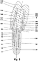
- the implant body (10) has a multi-stage recess (13) which is divided into three zones here, cf. Figure 3 .
- the first zone (14) - it lies in the area of the implant shoulder (12) of the implant body (10) - is, for example, an inner cone (14) which, for example, has a cone angle of, for example, 30 degrees at a height of 0.65 mm, cf. Figure 3 .
- the inner cone (14) merges - as part of the second zone (15) - into a configuration which serves as an anti-twist device and which, for example, has the shape of a hexagon socket.
- the hexagon socket (15) measures, for example, a width across flats of 2.1 mm at a height of 2.89 mm.
- the hexagon socket (15), which can also be, for example, a double hexagon socket or some other form-fitting or non-locking anti-rotation geometry, is optionally followed - not shown here - by a cylinder seat supporting the centering of the superstructure carrier (20) in the implant body (10).
- the cylinder seat which is short, for example, then has a diameter which corresponds to the width across flats of the hexagon socket (15).
- the third zone (17) is a threaded hole which, during assembly, receives the external hexagon screw (90) holding the superstructure carrier (20). Behind the end of the, for example, 2.9 mm long M 1.6 internal thread (18), there is, for example, a short cylindrical thread run-out.
- the suprastructural support (20), for example 7.67 mm long, has the primary task - sitting in the implant body (10) - to serve as the basis for the artificial tooth crown (120). It has an area (51) which faces the implant body (10) and an area (21) which receives the tooth crown (120) or the superstructure, cf. Figures 4 and 5 .
- the region (51) facing the implant body (10) is the hollow implant pin (50).
- This consists of an implant neck (52) with an average length of 1.04 mm, for example, with its outer cone (53), for example 0.94 mm long, a 1.5 mm long external hexagon (54) with a wrench size of 2.1 mm and, if necessary, a existing short cylinder attachment. The latter is not shown here.
- the outer cone (53) and the outer hexagon (54) sit precisely in the recess (13) of the implant body (10). In the axial direction pointing towards the tip of the implant body (10), the end faces of the external hexagon (54) and the possibly existing short cylinder attachment do not contact the recess (13).
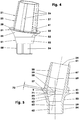
- the implant cone (53) there is a plate-like implant flange (31), for example, which emerges from the implant neck (52) with a continuous transition, cf. Figures 4 to 7 .
- the underside (32) of the, for example, round implant flange (31) has, at least in some areas, the shape of the jacket of a truncated cone, the cone angle of which opens towards the tooth crown (120). The cone angle is between 90 and 135 degrees, for example.
- the underside of the implant flange (31) also consists of a plurality of partially uneven conical cones protruding from one another, each enclosing a different angle with respect to the center line (29). The transitions between the cones may be rounded off.
- free-form surfaces can also be used.
- the outer edge (33) of the implant flange (31) has a possibly variable distance from the center line (29). In the exemplary embodiment, it is constant. It is, for example, 2.23 mm.
- the edge (33) is the outer boundary of the reference plane (38) or the end faces (77) according to the Figures 6 and 7 .
- the outer edge (33) experiences no height offset in the longitudinal direction of the center line (29) in the exemplary embodiment. In other exemplary embodiments, however, it is conceivable at least in some areas. It can then reach up to 2 mm, for example.
- the region (21) of the superstructure carrier (20) in the form of an implant post (23) as a positive interface part (141) extends above the implant flange (31).
- the hollow implant post (23), for example 4.03 mm high, has the shape of a straight hexagonal truncated pyramid.
- the truncated pyramid here has six long pyramid edges, in the area of which the cleats (26) are arranged.
- the radially outwardly oriented outer surfaces (27) of the studs (26) are partial surfaces of an imaginary envelope surface (28) in the form of, for example, a straight truncated cone jacket.
- the outer surfaces (27) can lie on, below or above the theoretical pyramid edges.
- the overhang or underhang can be up to 0.2 mm.
- the cone angle of the envelope surface (28) usually measures 5 to 12 degrees. Here the cone angle is, for example, 7.36 degrees.
- the frustoconical envelope surface (28) tapers with increasing distance from the implant flange (31). This envelope surface (28) is here the interface geometry (142) of the assembly joint (140) located between the implant post (23) and the adhesive body (100), which represents the interface (141, 145).
- the implant post (23) has, for example, in the vicinity of the implant flange (31) on one of the studs (26) an anti-rotation web (41), for example 0.85 mm long, which protrudes over the imaginary frustoconical envelope surface (28) by 0.25 mm, for example .
- the anti-rotation web (41) does not belong to the interface geometry (142).
- the average width of the anti-rotation web (41) is, for example, 0.58 mm.
- This special shape of the implant post (23) results in a torsion-proof base for the adhesive body (100) to be carried or the tooth crown (120) to be carried directly.
- the implant post (23) terminates with an upper side (24) which may also serve as a support surface.
- the latter, cf. Figure 5 is aligned here normal to the center line (29).
- the implant post (23) has, for example, a rounded transition area (34) towards the implant flange (31).
- the implant flange (31) has around the transition area (34), according to the Figures 4 and 5 , a - a plane (38) forming - flange top (37).
- the plane (38) delimited on the outside by the edge (33) is cut, for example, in the middle and perpendicularly by the center line (29).
- the large-area flange top (37) forms, among other things, a seating and supporting envelope for the adhesive body (100) and / or the tooth crown (120).
- the rounded transition area (34) can also be deepened by up to 0.2 mm in the axial direction parallel to the center line (29), so that a circumferential groove (35) is created between the flat flange top (37) and the implant post (23) , see. Figure 7 .
- the superstructure carrier (20) is equipped with a titanium nitride coating at least above the implant flange (31).
- Their layer thickness is, for example, 1 to 4 ⁇ m.
- thin-walled ceramic or copolymer coatings can also be applied there.
- the superstructure support (20) has a continuous cavity (61) which has a kink in the central area with an included angle of 73 ⁇ 13 degrees.
- the finished cavity (61) consists of three cavity zones.
- the lower cavity zone (62) belongs to the implant pin (50). It is, for example, a cylindrical bore with a length of, for example, 1.81 mm, the diameter of which is, for example, 1.73 mm.
- the upwardly expanding inner cone (65) adjoins them.
- the inner cone for example 1.08 mm high, has a cone angle of, for example, 30 degrees. It serves to support the head section of the screw (90) and lies below the reference plane (38).
- the bore (62) and the inner cone (65) have a common center line (63) which, for example, coincides with the center line (59) oriented on the outer wall of the implant pin (50).
- this bore (62) - with the prosthesis mounted - is traversed by the shaft (96) of the hexagon socket screw (90), the shaft (96) of which does not contact the wall of the bore (62).
- the upper cavity zone (67), which runs in the implant post (23), is a cylindrical bore, the diameter of which measures 2.42 mm, for example, with a length of 3.7 mm. It is used to introduce the screw (90) and to guide the tool with which the screw (90) is tightened.
- Your center line (69) is, for example, concentric to the outer wall-oriented Center line (29) of the implant post (23) aligned.
- the bore (67) ends, for example, approximately 0.33 mm in front of the reference plane (38) of the implant flange (31).
- Both center lines (63) and (69) intersect in the embodiment in the central cavity zone (64) at an intersection (71) which connects the upper (67) and the lower cavity zone (62) with one another.
- the central hollow zone (64) is a curved recess in which the bore (67) and the inner cone (65) adjoin one another, e.g. in edge-free tangential transitions.
- the interface (71) lies at a distance (72) below the reference plane (38). The distance here is e.g. 0.22 mm. This is made possible by a screw (90) seated deep in the superstructure carrier (20). The latter is thus located in the lower half of the superstructure carrier (20).
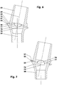
- the implant flange (31) of which has a frustoconical support envelope surface (75, 76) with the axis of rotation (79) instead of a flat flange top.
- the truncated cone surface (75) is oriented so that its imaginary tip lies in the area of the implant post (23).
- the cone angle (78) is after Figure 6 e.g. 150 degrees.
- the reference plane (38) becomes the Figure 5 replaced by the large end face (77) of the truncated cone jacket (75).
- the end face (77) is spanned by the edge (33) of the implant flange (31).
- the frustoconical jacket-shaped supporting envelope surface (76) of the implant flange (31) is curved downwards, whereby the imaginary tip of the truncated cone jacket points in the direction of the implant pin (59).
- the large end face (77) forms the reference plane (38) below which the Intersection (71) lies.
- the cone angle (78) measures 158 degrees, for example.
- the superstructure carrier (20) is a slim, thin-walled component that has only slight fluctuations in wall thickness over a wide area. Individual, above-average accumulations of material are constructively avoided.
- the superstructure beam (20) is cut lengthways in the plane that is spanned by the two center lines (59) and (69).
- the half-sided cross-sectional area which is enclosed by the outer and cavity contour of the component, there is a measuring circle (9) at the point of the largest accumulation of material, which rests at two points on the cross-sectional outer contour and at one point on the cross-sectional inner contour.
- This largest measuring circle (9) has a diameter which is smaller than 25 percent of the mean diameter of the cavity (62).
- an adhesive body (100) is glued or cemented onto the superstructure carrier (20), cf. ) is arranged. With its help, the angular position of the tooth crown (120) is adjusted to the angular position of the implant post (23).
- the adhesive body (100) essentially has a sleeve-like, for example largely rotationally symmetrical, shape. Its inner wall (105) is at least partially adapted - in the radial direction - to the envelope surface (28) of the implant post (23), being the interface geometry (146) of the negative interface part (145) of the interface (141, 145). An exception is that between the adhesive body (100) and the anti-rotation device (41) arranged on the superstructure carrier (20).
- the adhesive body (100) has a widened, for example, circumferential edge area (107) with which it is supported on the one hand - in the axial direction - on the flange top (37) of the superstructure carrier (20) and on the other hand it supports itself for the crown (120) offers at least regional axial support.
- the assembly play in the assembly joint (140) between the supporting superstructure carrier (20) and the attachable adhesive body (100) is, for example, 30 to 50 ⁇ m, so that the adhesive body (100) with the interposition of an adhesive (113) on the implant post (23) of the Suprastructure carrier (20) can rest over a large area.
- the adhesive body (100) has a groove (108) in its, for example, conical recess (106), e.g. in the lower area, on whose flanks the anti-rotation web (41) of the superstructure carrier ( 20).
- the groove (108) is not part of the interface geometry (146).
- the adhesive body (100) In the area of its upper side (102), the adhesive body (100) has a bore-like recess (106) which, when the prosthesis is mounted, represents an extension of the bore (67) of the implant post (23).
- the recess (106) can, if necessary, be filled with a filler (8) after the screw (90) has been screwed tight.
- Figure 8 shows an implant post (150) of the superstructure carrier (20) with a truncated cone-shaped interface geometry (142). It is an envelope surface (156) which is formed by the radial outer sides or head surfaces of the helically wound cleats (151) and an upper circumferential end ring web (152).
- the lugs (151) follow, for example, a helical line which is wound to the left and which, with the reference plane (38), includes an angle of inclination of, for example, 70 degrees.
- the studs (151) end in a circumferential adhesive groove (155).
- the latter reduces the out Figure 4 known regular supporting enveloping surface (37), for example by more than 60 percent.
- the cross-sections of the grooves (153, 154) and the channel (155) - they are oriented transversely to the longitudinal dimensions of these depressions - are a function of the viscosity of the adhesive to be used with which the interface parts (141) and (145) are glued together .
- the circumferential groove (154), the screw grooves (153) and the adhesive groove (155) represent a common gap (6) here, see FIG. 19.
- an implant post (160) which carries, for example, six studs (161) on a base surface (167) shaped like a truncated cone.
- a base surface (167) shaped like a truncated cone.
- three cleats (161) are arranged in such a way that their centers of gravity lie on one plane, the is cut normally from the center line (29).
- the lugs (161) are each distributed equidistantly on the circumference.
- the lugs (161) of the two levels are offset from one another by half a pitch.
- the individual cleat (161) is essentially cuboid in shape. Its length is 2.6 times its width.
- the height of the studs is e.g. 0.2 mm, which is 0.4 times the width.
- the radial outer sides of the studs (161) lie in the frustoconical envelope-shaped interface geometry (142) that forms the envelope surface (166).
- the center line (29) is offset from the center line (69) by 0.12 mm, for example.
- the center line (69) moves closer to the part of the central hollow zone (64), cf. Figure 5 whose height is the shortest.
- the negative interface part (145) of the in Figure 10 illustrated adhesive body (100). Its conical recess (106) forms the frustoconical jacket-shaped interface geometry (146).
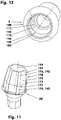
- the illustrated implant post (170) has an interface geometry (142) which consists of a lower cylindrical envelope surface (175) and an upper conical envelope surface (176).
- the latter has a cone angle of 18 degrees, for example.
- the height of the upper, longer envelope surface (176) corresponds, for example, to 1.8 times the lower, shorter envelope surface (175).
- the outer sides of the angled, upwardly tapering cleats (171), which are located in the envelope surfaces (175, 176) and whose central axes lie in one plane with the center line (69), are separated by wide grooves (172).
- the grooves (172) each have one towards the inside curved groove base (173).
- the groove bases (173) are parts of a cylinder and / or a cone jacket.
- the curvature of the groove base (173) in the lower region of the implant post (170) is, for example, 55 percent of the maximum diameter of the implant flange (31).
- the center line of curvature lies in one plane with the center line (69).
- the corresponding adhesive body (100) has a two-part inner wall, cf. Figure 12 .
- the part of the inner wall which adjoins the lower end face (103) is a partial cylindrical inner wall (115). This is followed in the direction of the top (102) by a frustoconical jacket-shaped partial inner wall (117).
- the implant post (180) has a comparable interface geometry (142).
- the lower enveloping surface - predetermined by the lower lugs (181) - is here also an enveloping cone (185), the cone angle of which is, for example, 10 degrees.
- the upper envelope cone (186) has a cone angle, which is e.g. 16 degrees.
- the studs (181) have an arrangement on the implant post (180) which corresponds to that of the implant post (160). The size of the studs can also be found in the variant there.
- the cleats (181) instead of the cuboid shape of the cleats (161), the cleats (181) have, for example, the shape of a feather key according to DIN 6885, Form A. However, the free outside of the cleats (181) is curved according to the envelope surfaces (185, 186).
- the center line (29) is also here offset from the center line (69) by 0.12 mm, for example, see the description of FIG.
- the Figures 15 and 17 each show a superstructure support (20), the implant post (190) of which has a base surface (197) in the shape of a truncated cone and which is occupied by a large number of cylindrical pins (191).
- the latter can also have another regular or irregular shape.
- the free, curved end faces of the pegs (191) also define a frustoconical envelope surface (195) here.
- the pins (191) have a diameter of 0.5 to 1 mm, for example.
- they are arranged on a helical line rising to the right, for example, which, for example, steadily decreases their distance from the center line (69) with increasing distance from the implant flange.
- the helix has a gradient of 5 to 15 degrees.
- the studs (191) are spaced apart from one another, which corresponds, for example, to one to two times their diameter.
- a pin (192) which, for example, has 1 to 2.5 times the length of a pin (191).
- the pin (192) serves as an anti-rotation element which engages in a corresponding groove (108) in the attachment element (5) after assembly, cf. Figure 16 .
- a groove (193), notch or the like machined into the implant post (190) can also be used to produce an anti-rotation device.
- a lug (109) After the attachment element (5) has been placed on, a lug (109), a web or another protruding structure of the attachment element (5) then engages in this groove (193), cf. Figure 18 .
- the interface geometries (142) or their areas can have a constant or a variable distance from the respective opposing base surfaces or their areas.
- the interface geometries (142) of the implant posts each have center lines (144) which are congruent with the associated center lines of the base surfaces (157, 167, 187, 188, 197).
- center lines (144) which are congruent with the associated center lines of the base surfaces (157, 167, 187, 188, 197).
- the hexagon socket screw (90) is divided into three areas: a head area (91), a shaft area (96) and a threaded area (97), cf. Figures 1 and 3 .
- the first area is the header area (91). It comprises a conical head section (92) and a tool holder (94) arranged thereon.
- the head section (92) for example 1.03 mm high, has the shape of a truncated cone which tapers in the direction of the thread region (97) and has, for example, a cone angle of 30 degrees.
- the conical area with which the screw (90) rests on the superstructure support (20) has a maximum length of, for example, 0.83 mm. Its largest diameter is 2.06 mm here.
- the head section (92) ends in an outwardly curved, conical head section end face (93), the cone angle of which is, for example, 160 degrees.
- a molded tool holder (94) which is a spherical external hexagon for a width across flats of 1.45 mm, sits on the head section end face (93).
- the external hexagon has six adjacent contact flanks, each made up of three surface sections exist.
- the upper and lower surface sections (85, 86) each extend over, for example, 0.4 mm of the tool holder height. Both surface sections are flat and each enclose, for example, an angle of 11.5 degrees with the screw center line (89).
- the upper ends of the upper surface sections (85) incline towards the screw center line (89) like the lower ends of the lower surface sections (86).
- a surface section (87) curved outwardly in an arc is arranged in each case. Its curvature, oriented transversely to the screw center line (89), has a radius of 0.9 mm, for example.
- a socket wrench with a hexagon socket can be placed on the tool holder (94) to tighten the screw (90). Due to the special arrangement of the upper and lower surface sections (85, 86), the tubular wrench does not experience any reaction force along its length when the torque is passed on. The front end face of the pipe wrench rolls on the frustoconical shell-shaped head section end face (93) of the screw head (92) with little friction and without interference.
- the conical area of the head section (92) is, for example, tangentially connected to the second area, that is to say the shaft area (96).
- the expansion screw-like shaft area (96) consists of a rotationally symmetrical waist, which has its smallest diameter, for example 1.3 mm, in the screw center area, for example 3.5 mm from the free end of the head area (91).
- the mean curvature of the outer contour of the waist has in section according to Figure 3 a radius of, for example, 4.44 mm.
- the third area is the threaded area (97). It has, for example, a rolled M1.6 thread, the usable length of which is, for example, 2.6 mm.
- the tooth crown (120) sits on an adhesive body (100).
- the inner wall (125) of the tooth crown (120) is adapted to the outer wall (101) of the adhesive body (100).
- the clearance between the outer wall (101) and the inner wall (125) is 30 to 50 ⁇ m.
- the adhesive body (100) and the tooth crown (120) are designed in the area of the edge (132) of their adhesive joint (131) so that the last tenths of a millimeter meet the joint outer surface of the prosthesis (2) at an angle of 90 ⁇ 10 degrees.
- the outer surface (121) of the tooth crown (120) and the outer surface (101) of the adhesive body (100) merge tangentially or at least almost tangentially. If there is a kink, its included angle is in a range that is less than 180 and greater than 175 degrees.
- the superstructure support (20) is thus secured against rotation by means of an implant cone (53) and the anti-rotation profile (54) and is screwed into the cone seat (14) of the implant body (10) by means of the screw (90).
- the implant neck (52) and the underside (32) of the implant flange (31) usually rest on the gums (not shown here).
- the combination of the adhesive body (100) and the artificial tooth crown (120) sits glued to the implant flange (31).
Landscapes
- Health & Medical Sciences (AREA)
- Oral & Maxillofacial Surgery (AREA)
- Orthopedic Medicine & Surgery (AREA)
- Dentistry (AREA)
- Epidemiology (AREA)
- Life Sciences & Earth Sciences (AREA)
- Animal Behavior & Ethology (AREA)
- General Health & Medical Sciences (AREA)
- Public Health (AREA)
- Veterinary Medicine (AREA)
- Dental Prosthetics (AREA)
- Prostheses (AREA)
- Soil Working Implements (AREA)
Description
- Die Erfindung betrifft einen Suprastrukturträger mit einem Aufsetzelement als Teil eines prothetischen Zahnersatzes zwischen einem Implantatkörper und einer Suprakonstruktion, mit einem hohlen Implantatpfosten, einem hohlen Implantatzapfen und einem dazwischen liegenden Implantatflansch. Die Aushöhlungszonen des Implantatpfostens und des Implantatzapfens gehen ineinander über. Deren Mittellinien schneiden sich. Auf dem Implantatpfosten ist das Aufsetzelement über eine - eine Schnittstelle bildende - Montagefuge verdrehsicher anordenbar.
- In der zahnärztlichen Implantologie wird u.a. im Rahmen der Herstellung eines prothetischen Einzelzahnersatzes häufig ein enossaler Implantatkörper verwendet, der die Prothese trägt. In diesem Fall wird der Implantatkörper, eine Art Schraubdübel, in einer künstlich im Patientenkiefer erzeugten Bohrung eingeschraubt. Der eingeschraubte Implantatkörper nimmt bei der fertigen Prothese einen Suprastrukturträger auf. Letzterer wird beispielsweise verdrehsicher im Implantatkörper mit einer speziellen Schraube verschraubt. Auf den Suprastrukturträger wird direkt oder indirekt eine die sichtbare Zahnkrone bildende Suprastruktur, z.B. durch Verkleben, aufgesetzt.
- Aus der
DE 20 2012 102 746 U1 ist ein Zahnimplantataufbausystem bekannt, bei dem ein Implantatkörper, ein Suprastrukturträger, ein Klebekörper und eine künstliche Krone einen künstlichen Zahnersatz bilden. - Die
WO 2014/012973 A2 beschreibt ein Zahnimplantataufbausystem, bei dem ein Implantatkörper, ein Suprastrukturträger, ein Klebekörper und eine künstliche Krone einen künstlichen Zahnersatz bilden. Der Suprastrukturträger hat zur Abstützung der künstlichen Krone eine zum Implantatpfosten orientierte Abstützhüllfläche, die eine abgesenkte bukkale Außenschulter aufweist. - Aus der
DE 10 2013 013 565 A1 ist ebenfalls ein Zahnimplantataufbausystem bekannt, bei dem die künstliche Krone auf einer zum Implantatpfosten hin orientierten räumlich gekrümmten Abstützhüllfläche aufliegt. - Der vorliegenden Erfindung liegt die Problemstellung zugrunde, einen Suprastrukturträger so zu verbessern, dass die zwischen dem Implantatpfosten und dem jeweiligen Aufsetzelement gelegene Schnittstelle ein sicheres und einfaches Fügen und Trennen der Schnittstellenbauteile ermöglicht.
- Diese Problemstellung wird mit den Merkmalen des Patentanspruchs 1 gelöst. Dabei ist das Aufsetzelement ist eine künstliche Krone, ein Verbund aus einem Klebekörper und einer Krone oder ein anderes kappenartiges Element. Zumindest Bereiche des Implantatflansches haben eine Abstützhüllfläche. Das Aufsatzelement hat eine Schnittstellengeometrie, die zumindest bereichsweise form- und/oder kraftschlüssig auf der Schnittstellengeometrie der Suprastrukturträger montierbar ist. Die jeweilige Schnittstellengeometrie hat unter Ausschluss eines oder mehrerer die Verdrehsicherung garantierenden Geometriebereiche eine äußere oder eine innere Hüllfläche. Der Implantatpfosten oder das Aufsetzelement weist jeweils eine Basisfläche auf, die mit der Hüllfläche desselben Bauteils einen Spaltraum einschließt, dessen mittlere Stärke mehr als 0,05 mm misst. Im Spalteraum stehen von der jeweiligen Basisfläche mehrere Erhebungen in Form von Stollen, Stegen, Zapfen, Nasen oder Noppen vom Implantatpfosten oder vom Aufsetzelement ab.
- Der Suprastrukturträger ist zwischen einem Implantatkörper und einer Suprastruktur angeordnet, wobei der Suprastrukturträger in einem klebekörper- und/oder kronentragenden Bereich einen Implantatpfosten und in dem dem Zahnfleisch und dem Implantatkörper zugewandten Bereich mindestens einen Implantathals aufweist. Der Suprastrukturträger wird aus einem Rohling gefertigt, der z.B. mittels eines Pulverspritzgießverfahrens hergestellt wird. Als Metallpulver wird hier beispielsweise die Titanlegierung Ti6Al4V verwendet. Der Rohling erhält im klebekörper- und/oder kronentragenden Bereich durch die Spritzgießform eine der Fertigform mathematisch ähnliche Form. Der Rohling erhält in dem dem Zahnfleisch und dem Implantatkörper zugewandten Bereich durch die Spritzgießform die Form eines Rohzapfens. Der Rohzapfen erhält durch mechanisch und/oder optisch trennende Bearbeitung seine Fertigform.
- Der Suprastrukturträger hat einen Implantatpfosten, dessen äußere Gestalt z.B. einem geraden Kegelstumpf entspricht. Der Implantatpfosten basiert auf dem Implantatflansch des Suprastrukturträgers, vom dem er senkrecht absteht. Der äußere Rand des Implantatflansches hat beispielsweise eine Kreisform, deren Mittelpunkt konzentrisch zur Mittellinie des Implantatpfostens orientiert ist. Auf diese Weise ist auf dem einzelnen Implantatpfosten als Aufsetzelement z.B. ein Klebekörper und/oder eine Zahnkrone dauerhaft aufsetzbar, der bzw. die z.B. aus einem rotationssymmetrischen Rohling gefertigt sind.
- Der Implantatpfosten und das Aufsetzelement haben eine gemeinsame Schnittstelle. Das Aufsetzelement kann auch ein nur temporär während der Prothesenfertigung und -anpassung verwendbares kappenartiges Element sein. Hier treffen die äußere Geometrieform des Implantatpfostens und die innere Geometrieform des Aufsetzelementes aufeinander. Zu dieser Schnittstelle gehören auch die Oberflächenbereiche des Implantatflansches, die dem Implantatpfosten zugewandt sind.
- Die Geometrieformen der Schnittstelle sind so gestaltet, dass die Aufsetzelemente während der Prothesenplanung, Fertigung und Anpassung mehrfach problemlos ohne Verkanten oder größeren Kraftaufwand auf den Suprastrukturträger wiederholgenau aufgesetzt und wieder abgenommen werden können. Muss das Aufsetzelement auf dem Implantatpfosten z.B. aufgeklebt oder aufzementiert werden, befinden sich zwischen den einander gegenüberliegenden Geometrieformen Hohl- oder Spalträume. Diese Hohl- oder Spalträume erstrecken sich entweder in Richtung Implantatpfosten und/oder in Richtung des jeweiligen Aufsetzelementes. Sie dehnen sich zudem primär quer zur Aufsetzrichtung des jeweiligen Aufsetzelements aus.
- U.a. um die Hohl- oder Spalträume zu schaffen, stehen vom Implantatpfosten und/oder vom Aufsetzelement mehrere Erhebungen in Form von Stollen, Stegen, Zapfen, Nasen, Noppen oder dergleichen ab. Sind z.B. auf einem konischen Implantatpfosten - auf dessen als Basisfläche bezeichneten Oberfläche - eine Vielzahl von gleichen Halbkugeln angeformt, bilden die am weitesten außenliegenden Punkte der sphärischen Krümmung der Halbkugeln eine Hüllfläche, die einen Kegelstumpfmantel darstellt. Der Zwischenraum zwischen der Basisfläche und der Hüllfläche bietet bei der Prothesenmontage den Füllraum für den Klebstoff oder den Zement der aushärtbaren kraftschlüssigen Verbindung zwischen den Schnittstellenteilen: Implantatpfosten und Aufsetzelement.
- Weitere Einzelheiten der Erfindung ergeben sich aus den Unteransprüchen und der nachfolgenden Beschreibung schematisch dargestellter Ausführungsformen.
- Figur 1:
- Explosionsmodell eines prothetischen Zahnersatzes;
- Figur 2:
- Seitenansicht des prothetischen Zahnersatzes;
- Figur 3:
- Längsschnitt durch einen prothetischen Zahnersatz, vergrößert;
- Figur 4:
- Suprastrukturträger, perspektivisch;
- Figur 5:
- Suprastrukturträger im Längsschnitt mit planer Abstützhüllfläche;
- Figur 6:
- wie
Figur 5 , jedoch mit nach oben gewölbter Abstützhüllfläche; - Figur 7:
- wie
Figur 5 , jedoch mit nach unten gewölbter Abstützhüllfläche; - Figur 8:
- perspektivisch dargestellter Suprastrukturträger mit schraubenförmigen Nuten;
- Figur 9:
- wie
Figur 8 , jedoch mit versetzt angeordneten Stollen; - Figur 10:
- perspektivisch dargestellter Klebekörper für den Suprastrukturträger nach
Figur 8 ; - Figur 11:
- perspektivisch dargestellter Suprastrukturträger mit einer zylinder- und konusförmigen Hüllfäche;
- Figur 12:
- perspektivisch dargestellter Klebekörper für den Suprastrukturträger nach
Figur 11 ; - Figur 13:
- perspektivisch dargestellter Suprastrukturträger mit einer aus zwei verschiedenen Kegelstumpfmänteln bestehenden Hüllfäche;
- Figur 14:
- perspektivisch dargestellter Klebekörper für den Suprastrukturträger nach
Figur 13 ; - Figur 15:
- perspektivisch dargestellter Suprastrukturträger mit einem zapfenbesetzten Implantatpfosten und zapfenartiger Verdrehsicherung;
- Figur 16:
- perspektivisch dargestellter Klebekörper für den Suprastrukturträger nach
Figur 15 ; - Figur 17:
- perspektivisch dargestellter Suprastrukturträger mit einem zapfenbesetzten Implantatpfosten und verdrehsichernden Nuten;
- Figur 18:
- perspektivisch dargestellter Klebekörper für den Suprastrukturträger nach
Figur 17 ; - Figur 19:
- verkleinerter Längsschnitt durch einen Suprastrukturträger nach
Figur 9 mit Klebekörper. - Die
Figur 1 zeigt beispielhaft alle Teile eines künstlichen Zahnes (1) in Form einer Explosionszeichnung. Als Basis dient ein hohlschraubenartiger Implantatkörper (10). Mit ihm wird ein Suprastrukturträger (20) mittels einer speziellen Außensechskantschraube (90) verdrehsicher verschraubt. Auf dem dann freien Ende des Suprastrukturträgers (20), einem Implantatpfosten (23), wird dann ein Aufsetzelement (5) adaptiert. Letzteres kann ein nur kurzzeitig verwendetes Mess- und/oder Abformmittel sein oder auch eine fertige Zahnkrone (120). Zwischen dem Implantatpfosten (23) und dem Aufsetzelement (5) befindet sich demnach eine Schnittstelle (141, 145), deren positiver Schnittstellenteil (141) verschiedene negative Schnittstellenteile (145) zeitlich nacheinander aufnehmen kann. - Der Implantatkörper (10) ist, nach den
Figuren 1 bis 3 , eine Hohlschraube mit einem ggf. selbstschneidenden, z.B. nichtmetrischen Außengewinde (11). Er weist z.B. bei einem Durchmesser von 3,53 mm eine Länge von 8,42 mm auf. Der Implantatkörper (10) hat eine mehrstufige Ausnehmung (13), die hier in drei Zonen aufgeteilt ist, vgl.Figur 3 . Die erste Zone (14) - sie liegt im Bereich der Implantatschulter (12) des Implantatkörpers (10) - ist beispielsweise ein Innenkonus (14), der z.B. bei einer Höhe von 0,65 mm einen Kegelwinkel von z.B. 30 Winkelgraden aufweist, vgl.Figur 3 . Der Innenkonus (14) geht - als Teil der zweiten Zone (15) - in eine als Verdrehsicherung dienende Ausgestaltung über, die z.B. die Form eines Innensechskants hat. Der Innensechskant (15) misst z.B. bei einer Höhe von 2,89 mm eine Schlüsselweite von 2,1 mm. An den Innensechskant (15), der z.B. auch ein Doppelinnensechskant oder eine andere form- oder kraftschlüssige Verdrehsicherungsgeometrie sein kann, schließt sich ggf. - hier nicht dargestellt - ein die Zentrierung des Suprastrukturträgers (20) im Implantatkörper (10) unterstützender Zylindersitz an. Der z.B. kurze Zylindersitz hat dann einen Durchmesser, der der Schlüsselweite des Innensechskants (15) entspricht. - Die dritte Zone (17) ist eine Gewindebohrung, die bei der Montage die den Suprastrukturträger (20) haltende Außensechskantschraube (90) aufnimmt. Hinter dem Ende des z.B. 2,9 mm langen M 1,6-Innengewindes (18) befindet sich z.B. ein kurzer zylindrischer Gewindeauslauf.
- Der z.B. 7,67 mm lange Suprastrukturträger (20) hat primär die Aufgabe - im Implantatkörper (10) sitzend - als Basis für die künstliche Zahnkrone (120) zu dienen. Er hat einen Bereich (51), der dem Implantatkörper (10) zugewandt ist und einen Bereich (21), der die Zahnkrone (120) bzw. die Suprastruktur aufnimmt, vgl.
Figuren 4 und 5 . - Der dem Implantatkörper (10) zugewandte Bereich (51) ist der hohle Implantatzapfen (50). Dieser besteht aus einem z.B. im Mittel 1,04 mm langen Implantathals (52) mit seinem z.B. 0,94 mm langen Außenkonus (53), einem z.B. 1,5 mm langen Außensechskant (54) der Schlüsselweite von 2,1 mm und einem ggf. vorhandenen kurzen Zylinderansatz. Letzterer ist hier nicht dargestellt.
- Der Außenkonus (53) und der Außensechskant (54) sitzen passgenau in der Ausnehmung (13) des Implantatkörpers (10). In der zur Spitze des Implantatkörpers (10) weisenden axialen Richtung kontaktieren die Stirnflächen des Außensechskants (54) und der ggf. vorhandene kurze Zylinderansatz die Ausnehmung (13) nicht.
- Oberhalb des Implantatkonusses (53) schließt sich ein beispielsweise tellerartiger Implantatflansch (31) an, der z.B. mit einem stetigen Übergang aus dem Implantathals (52) hervorgeht, vgl.
Figuren 4 bis 7 . Die Unterseite (32) des z.B. runden Implantatflansches (31) hat zumindest bereichsweise die Form des Mantels eines Kegelstumpfes, dessen Konuswinkel sich zur Zahnkrone (120) hin öffnet. Der Konuswinkel liegt z.B. zwischen 90 und 135 Winkelgraden. Ggf. besteht die Unterseite des Implantatflansches (31) auch aus mehreren auseinander hervorgehenden, teilweise ungeraden Kegelkonen, wobei jeder gegenüber der Mittellinie (29) einen anderen Winkel einschließt. Die Übergänge zwischen den Kegelkonen sind ggf. ausgerundet. - Anstelle eines Teils der Kegelkonen des Implantathalses (52) können auch Freiformflächen verwendet werden.
- Der äußere Rand (33) des Implantatflansches (31) hat hier einen ggf. veränderlichen Abstand zur Mittellinie (29). Im Ausführungsbeispiel ist er konstant. Er beträgt z.B. 2,23 mm. Der Rand (33) ist dabei die äußere Begrenzung der Bezugsebene (38) oder der Stirnflächen (77) nach den
Figuren 6 und 7 . Der äußere Rand (33) erfährt hierbei in Längsrichtung der Mittellinie (29) im Ausführungsbeispiel keinen Höhenversatz. Bei anderen Ausführungsbeispielen ist er jedoch zumindest bereichsweise denkbar. Er kann dann z.B. bis zu 2 mm erreichen. - Oberhalb des Implantatflansches (31) erstreckt sich der Bereich (21) des Suprastrukturträgers (20) in Form eines Implantatpfostens (23) als positives Schnittstellenteil (141). Der z.B. 4,03 mm hohe, hohle Implantatpfosten (23) hat hier die Form eines sechseckigen geraden Pyramidenstumpfes. Der Pyramidenstumpf hat hier sechs lange Pyramidenkanten, in deren Bereich die Stollen (26) angeordnet sind. Die radial nach außen orientierten Außenflächen (27) der Stollen (26) sind Teilflächen einer gedachten Hüllfläche (28) in Form eines z.B. geraden Kegelstumpfmantels. Die Außenflächen (27) können dabei auf, unter oder über den theoretischen Pyramidenkanten liegen. Der Über- oder Unterstand kann bis zu 0,2 mm betragen. Der Kegelwinkel der Hüllfläche (28) misst in der Regel 5 bis 12 Winkelgrade. Hier beträgt der Kegelwinkel z.B. 7,36 Winkelgrade. Die kegelstumpfmantelförmige Hüllfläche (28) verjüngt sich mit zunehmender Entfernung vom Implantatflansch (31). Diese Hüllfläche (28) ist hier die Schnittstellengeometrie (142) der zwischen dem Implantatpfosten (23) und dem Klebekörper (100) gelegenen Montagefuge (140), die die Schnittstelle (141, 145) darstellt.
- In den
Figuren 4 und 5 hat der Implantatpfosten (23) z.B. in der Nähe des Implantatflansches (31) auf einem der Stollen (26) einen z.B. 0,85 mm langen Verdrehsicherungssteg (41), der über die gedachte kegelstumpfmantelförmige Hüllfläche (28) um beispielsweise 0,25 mm übersteht. Der Verdrehsicherungssteg (41) gehört nicht zur Schnittstellengeometrie (142). Die Breite des Verdrehsicherungsstegs (41) beträgt im Mittel z.B. 0,58 mm. Durch diese spezielle Form des Implantatpfostens (23) ergibt sich eine verdrehsichernde Basis für den zu tragenden Klebekörper (100) bzw. die direkt zu tragende Zahnkrone (120). - Nach oben hin schließt der Implantatpfosten (23) mit einer ggf. auch als Auflagefläche dienenden Oberseite (24) ab. Letztere, vgl.
Figur 5 , ist hier normal zur Mittellinie (29) ausgerichtet. - Der Implantatpfosten (23) hat z.B. einen ausgerundeten Übergangsbereich (34) zum Implantatflansch (31) hin. Um den Übergangsbereich (34) herum hat der Implantatflansch (31), nach den
Figuren 4 und 5 , eine - eine Ebene (38) bildende - Flanschoberseite (37). Die durch den Rand (33) außen begrenzte Ebene (38) wird von der Mittellinie (29) z.B. mittig und senkrecht geschnitten. Die großflächige Flanschoberseite (37) bildet u.a. eine Aufsitz- und Abstützhüllfläche für den Klebekörper (100) und/oder die Zahnkrone (120). - Der ausgerundete Übergangsbereich (34) kann auch in axialer Richtung parallel zur Mittellinie (29) um bis zu 0,2 mm vertieft werden, so dass zwischen der flächigen Flanschoberseite (37) und dem Implantatpfosten (23) eine z.B. umlaufende Rinne (35) entsteht, vgl.
Figur 7 . - Zusätzlich ist der Suprastrukturträger (20) zumindest oberhalb des Implantatflansches (31) mit einer Titannitridbeschichtung ausgestattet. Ihre Schichtdicke beträgt z.B. 1 bis 4 µm. Alternativ können dort auch dünnwandige Keramik- oder Copolymerbeschichtungen aufgetragen sein.
- Nach
Figur 1 hat der Suprastrukturträger (20) eine durchgehende Aushöhlung (61), die im mittleren Bereich eine Knickstelle mit einem eingeschlossenen Winkel von 73 ± 13 Winkelgraden aufweist. Die fertig bearbeitete Aushöhlung (61) besteht aus drei Aushöhlungszonen. Die untere Aushöhlungszone (62) gehört zum Implantatzapfen (50). Sie ist z.B. eine zylindrische Bohrung der Länge von z.B. 1,81 mm, deren Durchmesser z.B. 1,73 mm beträgt. An sie schließt sich der nach oben aufweitende Innenkonus (65) an. Der z.B. 1,08 mm hohe Innenkonus hat einen Kegelwinkel von z.B. 30 Winkelgraden. Er dient der Auflage des Kopfabschnitts der Schraube (90) und liegt unterhalb der Bezugsebene (38). Die Bohrung (62) und der Innenkonus (65) haben eine gemeinsame Mittellinie (63), die sich z.B. mit der an der Außenwandung des Implantatzapfens (50) orientierenden Mittellinie (59) deckt. - Nach
Figur 3 wird diese Bohrung (62) - bei montierter Prothese - vom Schaft (96) der Außensechskantschraube (90) durchquert, wobei deren Schaft (96) die Wandung der Bohrung (62) nicht kontaktiert. - Die obere Aushöhlungszone (67), die im Implantatpfosten (23) verläuft, ist eine zylindrische Bohrung, deren Durchmesser z.B. bei einer Länge von 3,7 mm 2,42 mm misst. Sie dient der Einführung der Schraube (90) und der Führung des Werkzeuges, mit der die Schraube (90) angezogen wird. Ihre Mittellinie (69) ist z.B. konzentrisch zur außenwandungsorientierten Mittellinie (29) des Implantatpfostens (23) ausgerichtet. Die Bohrung (67) endet z.B. ca. 0,33 mm vor der Bezugsebene (38) des Implantatflansches (31).
- Beide Mittellinien (63) und (69) schneiden sich im Ausführungsbeispiel in der mittleren Aushöhlungszone (64) in einem Schnittpunkt (71), der die obere (67) und die untere Aushöhlungszone (62) miteinander verbindet. Die mittlere Aushöhlungszone (64) ist eine gekrümmte Ausnehmung, in der sich die Bohrung (67) und der Innenkonus (65), z.B. in kantenfreien tangentialen Übergängen, aneinander anschließen. Die Schnittstelle (71) liegt dabei im Abstand (72) unterhalb der Bezugsebene (38). Der Abstand beträgt hier z.B. 0,22 mm. Dies ermöglicht eine tief im Suprastrukturträger (20) sitzende Schraube (90). Letztere befindet sich somit in der unteren Hälfte des Suprastrukturträgers (20).
- In den
Figuren 6 und 7 sind zwei Suprastrukturträger (20) dargestellt, deren Implantatflansch (31) jeweils anstelle einer ebenen Flanschoberseite eine kegelstumpfmantelförmige Abstützhüllfläche (75, 76) mit der Rotationsachse (79) aufweist. NachFigur 6 ist die Kegelstumpfmantelfläche (75) so orientiert, dass ihre gedachte Spitze im Bereich des Implantatpfostens (23) liegt. Der Kegelwinkel (78) beträgt nachFigur 6 z.B. 150 Winkelgrade. In diesem Fall wird die Bezugsebene (38) derFigur 5 durch die große Stirnfläche (77) des Kegelstumpfmantels (75) ersetzt. Die Stirnfläche (77) wird vom Rand (33) des Implantatflansches (31) aufgespannt. - Nach
Figur 7 ist die kegelstumpfmantelförmige Abstützhüllfläche (76) des Implantatflansches (31) nach unten gewölbt, wodurch die gedachte Spitze des Kegelstumpfmantels in Richtung des Implantatzapfens (59) zeigt. Auch hier bildet die große Stirnfläche (77) die Bezugsebene (38), unterhalb welcher der Schnittpunkt (71) liegt. Der Kegelwinkel (78) misst nach Figur 7 z.B. 158 Winkelgrade. - Der Suprastrukturträger (20) ist ein schlankes dünnwandiges Bauteil, das über weite Bereiche nur geringe Wandstärkenschwankungen aufweist. Einzelne überdurchschnittliche Materialanhäufungen werden konstruktiv vermieden. Nach
Figur 5 ist der Suprastrukturträger (20) in der Ebene längsgeschnitten, die durch die beiden Mittellinien (59) und (69) aufgespannt wird. In der halbseitigen Querschnittsfläche, die durch die Außen- und Aushöhlungskontur des Bauteils umschlossen wird, befindet sich an der Stelle der größten Materialanhäufung ein Messkreis (9), der an zwei Stellen an der Querschnittsaußenkontur und an einer Stelle an der Querschnittsinnenkontur anliegt. Dieser größte Messkreis (9) hat einen Durchmesser, der kleiner ist als 25 Prozent des mittleren Durchmessers der Aushöhlung (62). - Auf den Suprastrukturträger (20) wird im Ausführungsbeispiel ein Klebekörper (100) aufgeklebt oder aufzementiert, vgl. Figuren 1 bis 3. Der Klebekörper (100) ist ein Hohlkörper, der innerhalb der Zahnprothese zwischen dem Suprastrukturträger (20) und der künstlichen Zahnkrone (120) angeordnet ist. Mit seiner Hilfe wird u.a. die Winkellage der Zahnkrone (120) an die Winkellage des Implantatpfostens (23) angeglichen.
- Der Klebekörper (100) hat im Wesentlichen eine hülsenförmige, z.B. weitgehend rotationssymmetrische Gestalt. Seine Innenwandung (105) ist zumindest bereichsweise - in Radialrichtung - an die Hüllfläche (28) des Implantatpfostens (23) angepasst, wobei sie die Schnittstellengeometrie (146) des negativen Schnittstellenteils (145) der Schnittstelle (141, 145) ist. Eine Ausnahme stellt die zwischen dem Klebekörper (100) und dem Suprastrukturträger (20) angeordnete Verdrehsicherung (41) dar.
- Der Klebekörper (100) hat einen verbreiterten, z.B. umlaufenden Randbereich (107), mit dem er sich einerseits - in Axialrichtung - an der Flanschoberseite (37) des Suprastrukturträgers (20) abstützt und mit dem er andererseits selbst für die Krone (120) eine zumindest bereichsweise axiale Abstützung bietet.
- Das Montagespiel in der Montagefuge (140) zwischen dem tragenden Suprastrukturträger (20) und dem aufsetzbaren Klebekörper (100) beträgt z.B. 30 bis 50 µm, so dass der Klebekörper (100) unter Zwischenlage eines Klebstoffes (113) auf dem Implantatpfosten (23) des Suprastrukturträgers (20) großflächig aufliegen kann.
- Um verdrehsicher auf dem Suprastrukturträger (20) sitzen zu können, hat der Klebekörper (100) in seiner beispielsweise konischen Ausnehmung (106), z.B. im unteren Bereich, eine Nut (108), an deren Flanken sich der Verdrehsicherungssteg (41) des Suprastrukturträgers (20) abstützt. Die Nut (108) ist nicht Teil der Schnittstellengeometrie (146).
- Im Bereich seiner Oberseite (102) weist der Klebekörper (100) eine bohrungsartige Ausnehmung (106) auf, die bei montierter Prothese eine Verlängerung der Bohrung (67) des Implantatpfostens (23) darstellt. Die Ausnehmung (106) kann nach dem Festschrauben der Schraube (90) ggf. mit einem Füllstoff (8) befüllt werden.
- Für den Implantatpfosten (23) und das jeweilige Aufsetzmittel (5) gibt es einige alternative Schnittstellengeometrien (142, 146), die in den
Figuren 8 bis 18 einzeln dargestellt werden. -
Figur 8 zeigt einen Implantatpfosten (150) des Suprastrukturträgers (20) mit kegelstumpfmantelförmiger Schnittstellengeometrie (142). Sie ist eine Hüllfläche (156), die durch die radialen Außenseiten bzw. Kopfflächen der schraubenförmig gewundenen Stollen (151) und einen oberen umlaufenden Abschlussringsteg (152) gebildet wird. Die Stollen (151) folgen z.B. einer nach links gewundenen Schraubenlinie, die mit der Bezugsebene (38) einen Steigungswinkel von z.B. 70 Winkelgraden einschließt. Zwischen dem Abschlussringsteg (152) und den nachFigur 8 oberen Enden der Stollen (151) befindet sich eine Umlaufnut (154), in die die zwischen den Stollen (151) gelegenen Schraubnuten (153) münden. - Im Bereich des Implantatflansches enden die Stollen (151) in einer umlaufenden Kleberinne (155). Letztere verringert die aus
Figur 4 bekannte reguläre Abstützhüllfläche (37) z.B. um mehr als 60 Prozent. Die Querschnitte der Nuten (153, 154) und der Rinne (155) - sie sind quer zu den Längsausdehnungen dieser Vertiefungen orientiert - sind eine Funktion der Viskosität des zu verwendenden Klebstoffes, mit dem die Schnittstellenteile (141) und (145) miteinander verklebt werden. Die Umlaufnut (154), die Schraubnuten (153) und die Kleberinne (155) stellen hier einen gemeinsamen Spaltraum (6) dar, vgl. Figur 19. - In der
Figur 9 ist ein Implantatpfosten (160) gezeigt, der z.B. sechs Stollen (161) auf einer kegelstumpfmantelförmigen Basisfläche (167) trägt. Jeweils drei Stollen (161) sind so angeordnet, dass ihre Schwerpunkte auf einer Ebene liegen, die von der Mittellinie (29) normal geschnitten wird. Die Stollen (161) sind jeweils äquidistant auf dem Umfang verteilt. Die Stollen (161) der beiden Ebenen sind zueinander jeweils um eine halbe Teilung versetzt. - Der einzelne Stollen (161) hat im Wesentlichen eine quaderförmige Gestalt. Seine Länge entspricht dem 2,6-fachen seiner Breite. Die Höhe der Stollen beträgt z.B. 0,2 mm, was das 0,4-fache der Breite ist. Die radialen Außenseiten der Stollen (161) liegen in der die Hüllfläche (166) bildenden kegelstumpfmantelförmigen Schnittstellengeometrie (142).
- Im vorliegenden Fall ist die Mittellinie (29) gegenüber der Mittellinie (69) um z.B. 0,12 mm versetzt. Die Mittellinie (69) rückt dabei näher an den Teil der mittleren Aushöhlungszone (64) heran, vgl.
Figur 5 , dessen Höhe am kürzesten ist. - Zu dem Implantatpfosten (150) passt als Schnittstellennegativteil (145) der in
Figur 10 dargestellte Klebekörper (100). Seine konische Ausnehmung (106) bildet die kegelstumpfmantelförmige Schnittstellengeometrie (146). - Nach
Figur 11 hat der dargestellte Implantatpfosten (170) eine Schnittstellengeometrie (142), die aus einer unteren zylindrischen Hüllfläche (175) und einer oberen konischen Hüllfläche (176) besteht. Letztere hat einen Kegelwinkel von z.B. 18 Winkelgraden. Die Höhe der oberen längeren Hüllfläche (176) entspricht z.B. dem 1,8-fachen der unteren kürzeren Hüllfläche (175). Die in den Hüllflächen (175, 176) gelegenen Außenseiten der abgewinkelten, sich nach oben verjüngenden Stollen (171), deren Mittelachsen jeweils mit der Mittellinie (69) in einer Ebene liegen, werden durch breite Nuten (172) getrennt. Die Nuten (172) haben hierbei jeweils einen nach innen gekrümmten Nutgrund (173). Die Nutgründe (173) sind Teile eines Zylinders und/oder eines Kegelmantels. Die Krümmung des Nutgrundes (173) beträgt im unteren Bereich des Implantatpfostens (170) z.B. 55 Prozent des Maximaldurchmessers des Implantatflansches (31). Dabei liegt die Krümmungsmittellinie mit der Mittellinie (69) in einer Ebene. - Der entsprechende Klebekörper (100) hat eine zweiteilige Innenwandung, vgl.
Figur 12 . Der Teil der Innenwandung, der sich an die untere Stirnseite (103) anschließt, ist eine zylindrische Teilinnenwandung (115). Auf sie folgt in Richtung der Oberseite (102) eine kegelstumpfmantelförmige Teilinnenwandung (117). - Der Implantatpfosten (180) hat eine vergleichbare Schnittstellengeometrie (142). Allerdings ist hier auch die untere - von den unteren Stollen (181) vorgegebene - Hüllfläche ein Hüllkonus (185), dessen Kegelwinkel z.B. 10 Winkelgrade beträgt. Der obere Hüllkonus (186) hat einen Kegelwinkel, der z.B. bei 16 Winkelgraden liegt. Die Stollen (181) haben auf dem Implantatpfosten (180) eine Anordnung, die der des Implantatpfostens (160) entspricht. Auch die Stollengröße ist der dortigen Variante zu entnehmen. Die Stollen (181) haben anstelle der Quaderform der Stollen (161) z.B. die Form einer Passfeder nach DIN 6885, Form A. Allerdings ist die freie Außenseite der Stollen (181) gemäß der Hüllflächen (185, 186) gekrümmt.
- Die Mittellinie (29) ist auch hier gegenüber der Mittellinie (69) um z.B. 0,12 mm versetzt, vgl. Beschreibung zu Figur 9.
- Die
Figuren 15 und 17 zeigen jeweils einen Suprastrukturträger (20), dessen Implantatpfosten (190) eine kegelstumpfmantelförmige Basisfläche (197) hat, die mit einer Vielzahl von zylinderförmigen Zapfen (191) besetzt ist. Letztere können auch eine andere regelmäßige oder unregelmäßige Gestalt haben. Die freien, gekrümmten Stirnseiten der Zapfen (191) definieren auch hier eine kegelstumpfmantelförmige Hüllfläche (195). Die Zapfen (191) haben z.B. einen Durchmesser von 0,5 bis 1 mm. Sie sind im Ausführungsbeispiel auf einer z.B. rechtssteigenden Schraubenlinie angeordnet, die ihren Abstand mit zunehmender Entfernung von Implantatflansch gegenüber der Mittellinie (69) z.B. stetig verringert. Die Schraubenlinie hat hierbei eine Steigung von 5 bis 15 Winkelgraden. Auf der Schraubenlinie haben die Stollen (191) einen gegenseitigen Abstand, der z.B. dem Ein- bis Zweifachen ihres Durchmessers entspricht. - In der Nähe des Implantatflansches befindet sich nach
Figur 15 ein Zapfen (192), der z.B. die 1 - 2,5-fache Länge eines Zapfens (191) aufweist. Der Zapfen (192) dient als Verdrehsicherungselement, das in eine entsprechende Nut (108) des Aufsetzelements (5) nach der Montage eingreift, vgl.Figur 16 . - Anstelle dieses positiv aus der Gestalt des Implantatpfostens (190) hervorstehenden Verdrehsicherungselements (191) kann für die Herstellung einer Verdrehsicherung auch eine in den Implantatpfosten (190) eingearbeitete Nut (193), Kerbe oder dergleichen verwendet werden. In diese Nut (193) greift dann nach dem Aufsetzen des Aufsetzelements (5) eine Nase (109), ein Steg oder eine andere hervorstehende Struktur des Aufsetzelementes (5) hinein, vgl.
Figur 18 . - Bei allen Implantatpfosten (23, 150, 160, 180, 190) können die Schnittstellengeometrien (142) oder deren Bereiche von den jeweiligen gegenüberliegenden Basisflächen oder deren Bereiche einen konstanten oder einen variablen Abstand haben.
- In der Regel haben die Schnittstellengeometrien (142) der Implantatpfosten jeweils Mittellinien (144), die deckungsgleich zu den zugehörigen Mittellinien der Basisflächen (157, 167, 187, 188, 197) sind. Abweichungen hiervon sind jedoch denkbar. Vergleichbares gilt auch für die Schnittstellengeometrien (146) der Aufsetzelemente (5) und deren Mittellinien (148).
- Die Außensechskantschraube (90) ist in drei Bereiche aufgeteilt: einen Kopfbereich (91), einen Schaftbereich (96) und einen Gewindebereich (97), vgl.
Figuren 1 und3 . Der erste Bereich ist der Kopfbereich (91). Er umfasst einen konusförmigen Kopfabschnitt (92) und eine darauf angeordnete Werkzeugaufnahme (94). Der z.B. 1,03 mm hohe Kopfabschnitt (92) hat die Form eines sich in Richtung Gewindebereich (97) verjüngenden Kegelstumpfes, der z.B. einen Kegelwinkel von 30 Winkelgraden aufweist. Der konusförmige Bereich, mit dem die Schraube (90) am Suprastrukturträger (20) anliegt, hat eine maximale Länge von z.B. 0,83 mm. Sein größter Durchmesser misst hier 2,06 mm. - Der Kopfabschnitt (92) endet in einer nach außen gewölbten, kegeligen Kopfabschnittsstirnfläche (93), deren Kegelwinkel z.B. 160 Winkelgrade beträgt. Auf der Kopfabschnittsstirnfläche (93) sitzt eine angeformte Werkzeugaufnahme (94), die einen kugelartigen Außensechskant für eine Schlüsselweite von 1,45 mm darstellt. Der Außensechskant weist sechs nebeneinander liegende Anlageflanken auf, die jeweils aus drei Flächenabschnitten bestehen. Der obere und der untere Flächenabschnitt (85, 86) erstreckt sich jeweils über z.B. 0,4 mm der Werkzeugaufnahmehöhe. Beide Flächenabschnitte sind eben und schließen mit der Schraubenmittellinie (89) jeweils z.B. einen Winkel von 11,5 Winkelgraden ein. Die oberen Enden der oberen Flächenabschnitte (85) neigen sich wie die unteren Enden der unteren Flächenabschnitte (86) zur Schraubenmittellinie (89) hin. Zwischen zwei übereinander angeordneten planen Flächenabschnitten (85, 86) ist jeweils ein bogenförmig nach außen gekrümmter Flächenabschnitt (87) angeordnet. Seine quer zur Schraubenmittellinie (89) orientierte Krümmung weist einen Radius von z.B. 0,9 mm auf.
- Auf die Werkzeugaufnahme (94) ist zum Festziehen der Schraube (90) ein Rohrschlüssel mit Innensechskant aufsetztbar. Durch die spezielle Anordnung der oberen und unteren Flächenabschnitte (85, 86) erfährt der Rohrschlüssel bei der Drehmomentweitergabe keine Reaktionskraft entlang seiner Längsausdehnung. Die vordere Stirnseite des Rohrschlüssels wälzt auf der kegelstumpfmantelförmigen Kopfabschnittsstirnfläche (93) des Schraubenkopfes (92) reibungsarm und störungsfrei ab.
- An den konusförmigen Bereich des Kopfabschnitts (92) schließt sich beispielsweise tangential der zweite Bereich, also der Schaftbereich (96) an. Der dehnschraubenartige Schaftbereich (96) besteht aus einer rotationssymmetrischen Taille, die im Schraubenmittenbereich, z.B. 3,5 mm vom freien Ende des Kopfbereiches (91) entfernt, ihren kleinsten Durchmesser, z.B. 1,3 mm, hat. Die mittlere Krümmung der Außenkontur der Taille hat im Schnitt nach
Figur 3 einen Radius von z.B. 4,44 mm. - Der dritte Bereich ist der Gewindebereich (97). Er weist ein z.B. gerolltes M1, 6-Gewinde auf, dessen nutzbare Länge z.B. 2,6 mm beträgt.
- Nach dem Ausführungsbeispiel sitzt die Zahnkrone (120) auf einem Klebekörper (100). Demnach ist die Innenwandung (125) der Zahnkrone (120) an die Außenwandung (101) des Klebekörpers (100) angepasst. Auch hier liegt das sich zwischen der Außenwandung (101) und Innenwandung (125) befindende Spiel bei 30 bis 50 um. Der Klebekörper (100) und die Zahnkrone (120) sind im Bereich des Randes (132) ihrer Klebefuge (131) so gestaltet, dass die letzten zehntel Millimeter in einem Winkel von 90 ± 10 Winkelgraden auf die gemeinsame Prothesenaußenfläche (2) treffen. Im Bereich des Randes ihrer Klebefuge (131) gehen die Außenfläche (121) der Zahnkrone (120) und die Außenfläche (101) des Klebekörpers (100) tangential oder zumindest fast tangential ineinander über. Sollte dort ein Knick vorgesehen sein, so liegt sein eingeschlossener Winkel in einem Bereich, der kleiner als 180 und größer als 175 Winkelgrade ist.
- Nach
Figur 3 sitzt somit bei der fertigen Prothese der Suprastrukturträger (20) mittels eines Implantatkonus (53) und des Verdrehsicherungsprofils (54) verdrehsicher und mittels der Schraube (90) verschraubt im Konussitz (14) des Implantatkörpers (10). Der Implantathals (52) und die Unterseite (32) des Implantatflansches (31) liegen in der Regel am hier nicht dargestellten Zahnfleisch an. Auf dem Implantatflansch (31) sitzt verklebt die Kombination aus dem Klebekörper (100) und der künstlichen Zahnkrone (120). - In der Druckschrift werden mehrere Textstellen erwähnt, nach denen Ebenen senkrecht, z.B. von Mittellinien, geschnitten sind. In diesen Fällen sollen Winkelabweichungen von ± 2 Winkelgraden noch zu senkrecht zählen.
-
- 1
- Zahnersatz, prothetisch
- 2
- Prothesenaußenfläche
- 5
- Aufsetzelement, Messmittel, Abformmittel negativer Schnittstellenteil
- 6
- Spaltraum, Füllraum, Zwischenraum
- 8
- Zement, Klebstoff, Füllstoff
- 9
- Messkreis
- 10
- Implantatkörper
- 11
- Außengewinde
- 12
- Implantatschulter
- 13
- Ausnehmung, gestuft
- 14
- Innenkonus, erste Zone, Konus, Konussitz
- 15
- Innensechskant, zweite Zone, Gegenprofil
- 17
- Gewindebohrung, dritte Zone
- 18
- Innengewinde
- 19
- Mittellinie von (10)
- 20
- Suprastrukturträger Teil eines Hybridabutments
- 21
- Bereich, der Zahnkrone zugewandt
- 23
- Implantatpfosten, positiver Schnittstellenteil
- 24
- Oberseite, Auflagefläche
- 26
- Stollen
- 27
- Außenfläche, radial
- 28
- Hüllfläche
- 29
- Mittellinie von (23)
- 31
- Implantatflansch
- 32
- Unterseite, dem Zahnfleisch zugewandte Fläche
- 33
- Rand
- 34
- Übergangsbereich, Ausrundung
- 35
- Rinne
- 37
- Flanschoberseite, Abstützhüllfläche
- 38
- Ebene, Bezugsebene
- 41
- Verdrehsicherungssteg, Verdrehsicherung
- 50
- Implantatzapfen
- 51
- Bereich, dem Implantatkörper zugewandt
- 52
- Implantathals
- 53
- Implantatkonus, Außenkonus
- 54
- Verdrehsicherungsprofil, Außensechskant
- 59
- Mittellinie von (50)
- 61
- Aushöhlung, geknickt; Schraubeneinführausnehmung
- 62
- untere Aushöhlungszone; Bohrung, zylindrisch
- 63
- Mittellinie von (62)
- 64
- mittlere Aushöhlungszone
- 65
- Schraubenkopfsitzfläche, Innenkonus, Aushöhlungszone
- 67
- obere Aushöhlungszone; Bohrung, zylindrisch
- 69
- Mittellinie von (67)
- 71
- Schnittpunkt
- 72
- Abstand zwischen (38) und (71)
- 73
- Oberkante von (65)
- 75
- Kegelstumpfmantelfläche, Abstützhüllfläche; nach oben gewölbt
- 76
- Kegelstumpfmantelfläche, Abstützhüllfläche; nach unten gewölbt
- 77
- Stirnfläche, groß von (75) oder (76)
- 78
- Kegelwinkel von (75) oder (76)
- 79
- Mittellinie, Rotationsachse von (75, 76)
- 85, 86
- Flächenabschnitte von (94), plan
- 87
- Flächenabschnitte von (94), gekrümmt
- 89
- Schraubenmittellinie
- 90
- Außensechskantschraube, Schraube
- 91
- Kopfbereich
- 92
- Kopfabschnitt, konusförmig; Schraubenkopf
- 93
- Kopfabschnittsstirnfläche
- 94
- Werkzeugaufnahme; Außensechskant, kugelartig
- 96
- Schaftbereich, Taille, Schaft
- 97
- Gewindebereich, Gewinde
- 100
- Klebekörper, Teil eines Hybridabutments, negativer Schnittstellenteil
- 101
- Außenwandung, Außenfläche
- 102
- Oberseite
- 103
- Stirnseite, unten
- 105
- Innenwandung, Innenfläche, gesamt
- 106
- Ausnehmung, kegelstumpfmantelförmig
- 107
- Randbereich
- 108
- Nut, Verdrehsicherungsnut
- 109
- Verdrehsicherungsnase
- 111
- Klebefuge zwischen (23) und (100)
- 113
- Klebstoff
- 115
- Teilinnenwandung, zylindrisch, implantatflanschnah
- 116
- Teilinnenwandung, kegelstumpfmantelförmig, implantatflanschnah
- 117
- Teilinnenwandung, kegelstumpfmantelförmig implantatflanschfern
- 120
- Zahnkrone, künstlich, Suprakonstruktion, ggf. negativer Schnittstellenteil
- 121
- Außenwandung, Außenfläche
- 125
- Innenwandung, Innenfläche
- 131
- Klebefuge zwischen (100) und (120)
- 132
- Klebefugenrand
- 133
- Klebstoff
- 140
- Montagefuge zwischen (23) und (100)
- 141
- Schnittstelle; Positivteil
- 142
- Schnittstellengeometrie von (141)
- 144
- Mittellinie von (142)
- 145
- Schnittstelle; Negativteil
- 146
- Schnittstellengeometrie von (145)
- 148
- Mittellinie von (146)
- 150
- Implantatpfosten mit geschraubten Stollen
- 151
- Stollen, schraubenförmig gewunden
- 152
- Abschlussringsteg
- 153
- Schraubnuten
- 154
- Umlaufnut
- 155
- Rinne
- 156
- Hüllfläche, kegelmantelförmig
- 157
- Basisfläche, kegelmantelförmig
- 160
- Implantatpfosten mit versetzten Stollen
- 161
- Stollen, im Wesentlichen quaderförmig
- 166
- Hüllfläche, kegelmantelförmig
- 167
- Basisfläche, kegelmantelförmig
- 170
- Implantatpfosten mit geknickten Stollen
- 171
- Stollen, abgeknickt
- 172
- Nuten
- 173
- Nutgrund, nach innen gewölbt
- 175
- Hüllzylinder; Hüllfläche, zylindrisch
- 176
- Hüllkonus; Hüllfläche kegelstumpfmantelförmig
- 180
- Implantatpfosten mit versetzten Passfederstollen
- 181
- Stollen, passfederförmig
- 185
- Hüllkonus, unten; Hüllfläche, kegelstumpfmantelförmig
- 186
- Hüllkonus, oben; Hüllfläche, kegelstumpfmantelförmig
- 187, 188
- Basisflächen; unten, oben
- 190
- Implantatpfosten mit versetzten Zapfen
- 191
- Zapfen, zylinder- oder kegelstumpfförmig; Stollen
- 192
- Verdrehsicherungsstollen
- 193
- Verdrehsicherungsnuten
- 195
- Hüllfläche, kegelstumpfmantelförmig
- 197
- Basisfläche
Claims (7)
- Suprastrukturträger (20) mit einem Aufsetzelement (5) als Teil eines prothetischen Zahnersatzes (1) zwischen einem Implantatkörper (10) und einer Suprakonstruktion, mit einem hohlen Implantatpfosten (23, 150, 160, 170, 180, 190), einem hohlen Implantatzapfen (50) und einem dazwischen liegenden Implantatflansch (31), wobei die Aushöhlungszonen (67, 62) des Implantatpfostens (23, 150, 160, 170, 180, 190) und des Implantatzapfens (50) ineinander übergehen und deren Mittelinien (69, 63) sich schneiden und wobei auf dem Implantatpfosten (23, 150, 160, 170, 180, 190) das Aufsetzelement (5) über eine - eine Schnittstelle (141, 145) bildende - Montagefuge (140) verdrehsicher anordenbar ist,- wobei das Aufsetzelement (5) eine künstliche Krone (120), ein Verbund aus einem Klebekörper (100) und einer Krone (120) oder ein anderes kappenartiges Element ist,- wobei zumindest Bereiche des Implantatflansches (31) eine Abstützhüllfläche (37) haben,- wobei das Aufsetzelement (5) eine Schnittstellengeometrie (146) hat, die zumindest bereichsweise form- und/oder kraftschlüssig auf der Schnittstellengeometrie (142) des Suprastrukturträgers (20) montierbar ist,- wobei die jeweilige Schnittstellengeometrie (142, 146) unter Ausschluss eines oder mehrerer die Verdrehsicherung garantierenden Geometriebereiche (41, 108, 109, 192, 193) eine äußere (28, 156, 166, 175, 176, 185, 186, 195) oder eine innere Hüllfläche hat,- wobei der Implantatpfosten (23, 150, 160, 170, 180, 190) oder das Aufsetzelement (5) jeweils eine Basisfläche (157, 167, 187, 188, 197) aufweist, die mit der Hüllfläche (28, 156, 166, 175, 176, 185, 186, 195) desselben Bauteils einen Spaltraum (6) einschließt, dessen mittlere Stärke mehr als 0,05 mm misst und- wobei im Spaltraum (6) von der jeweiligen Basisfläche (157, 167, 187, 188, 197) mehrere Erhebungen in Form von Stollen, Stegen, Zapfen, Nasen oder Noppen vom Implantatpfosten (23, 150, 160, 170, 180, 190) oder vom Aufsetzelement (5) abstehen.
- Suprastrukturträger nach Anspruch 1, dadurch gekennzeichnet, dass die äußere (28, 156, 166, 175, 176, 185, 186, 195) und/oder innere Hüllfläche der Schnittstellengeometrie (142, 146) jeweils eine Mittellinie (144, 148) hat, die entweder die Abstützhüllfläche (37) senkrecht schneidet oder mit deren Rotationsache (79) zusammenfällt.
- Suprastrukturträger nach Anspruch 1, dadurch gekennzeichnet, dass sich die Schnittstellengeometrien (142, 146) aus einem Zylindermantel, einem Kegelstumpfmantel oder aus mehreren gleichartigen oder verschiedenen Mänteln zusammensetzen.
- Suprastrukturträger nach Anspruch 3, dadurch gekennzeichnet, dass die Mittellinien (144, 148) der einzelnen Mäntel oder Mantelkombinationen der Schnittstellengeometrien (142, 146) zueinander deckungsgleich sind.
- Suprastrukturträger nach Anspruch 1, dadurch gekennzeichnet, dass die Abstützhüllfläche (37) entweder eine Ebene (38) oder eine Kegelstumpfmantelfläche (75, 76) ist.
- Suprastrukturträger nach Anspruch 5, dadurch gekennzeichnet, dass bei einer kegelstumpfmantelförmigen Abstützhüllfläche (75, 76) die theoretische Kegelspitze dem Implantatpfosten (23, 150, 160, 170, 180, 190) oder dem Implantatzapfen (50) zugewandt ist.
- Suprastrukturträger nach Anspruch 5, dadurch gekennzeichnet, dass der Kegelwinkel der kegelstumpfmantelförmigen Abstützhüllfläche (75, 76) zwischen 180 und 165 Winkelgraden liegt.
Applications Claiming Priority (2)
| Application Number | Priority Date | Filing Date | Title |
|---|---|---|---|
| DE102016008669.6A DE102016008669B4 (de) | 2016-07-20 | 2016-07-20 | Suprastrukturträger mit besonderer Implantatpfostengeometrie |
| PCT/DE2017/000212 WO2018014897A1 (de) | 2016-07-20 | 2017-07-18 | Suprastrukturträger mit besonderer implantatpfostengeometrie |
Publications (2)
| Publication Number | Publication Date |
|---|---|
| EP3487442A1 EP3487442A1 (de) | 2019-05-29 |
| EP3487442B1 true EP3487442B1 (de) | 2021-12-29 |
Family
ID=59631501
Family Applications (1)
| Application Number | Title | Priority Date | Filing Date |
|---|---|---|---|
| EP17752276.0A Active EP3487442B1 (de) | 2016-07-20 | 2017-07-18 | Suprastrukturträger mit besonderer implantatpfostengeometrie |
Country Status (8)
| Country | Link |
|---|---|
| US (1) | US11564779B2 (de) |
| EP (1) | EP3487442B1 (de) |
| JP (1) | JP7101657B2 (de) |
| KR (1) | KR102489389B1 (de) |
| CN (1) | CN109640870B (de) |
| BR (1) | BR112019001256B1 (de) |
| DE (1) | DE102016008669B4 (de) |
| WO (1) | WO2018014897A1 (de) |
Families Citing this family (15)
| Publication number | Priority date | Publication date | Assignee | Title |
|---|---|---|---|---|
| DE102016008669B4 (de) * | 2016-07-20 | 2018-10-11 | Bruno Spindler | Suprastrukturträger mit besonderer Implantatpfostengeometrie |
| DE102016008668B4 (de) * | 2016-07-20 | 2018-10-25 | Bruno Spindler | Suprastrukturträger mit besonderer Innen- und Außengeometrie |
| WO2018184119A1 (en) * | 2017-04-07 | 2018-10-11 | Panthera Dental Inc. | Drop-shaped screw conduit for a dental superstructure and designing method thereof |
| DE102018113237A1 (de) * | 2018-06-04 | 2019-12-05 | TRI Dental Implants Int. AG | Zahnimplantat und Zahnprothese |
| DE102018119612A1 (de) * | 2018-08-13 | 2020-02-13 | Curd Gadau | Abutmentsystem |
| WO2020153198A1 (ja) * | 2019-01-25 | 2020-07-30 | 佐藤 文昭 | 歯冠修復物 |
| DE102019203348A1 (de) * | 2019-03-12 | 2020-09-17 | Tim Übermuth | Abformeinrichtung für ein Dentalimplantat |
| AT522914A1 (de) * | 2019-09-03 | 2021-03-15 | Eap® Produktions Und Patentverwertungs Gmbh | Verfahren zur Herstellung eines Computermodells für ein Abutment und eines Abutments |
| RU197474U1 (ru) * | 2019-09-05 | 2020-04-29 | Федеральное государственное бюджетное образовательное учреждение высшего образования "Воронежский государственный медицинский университет им. Н.Н. Бурденко" Министерства здравоохранения Российской Федерации | Металлическое основание для абатмента из полиэфирэфиркетона |
| DE102019007624A1 (de) * | 2019-11-04 | 2021-05-06 | Bruno Spindler | Systemmontageschnittstelle |
| KR102099062B1 (ko) * | 2019-12-10 | 2020-04-08 | 장천석 | 교합고경의 안정적인 치수 조절이 가능한 임플란트의 어뷰트먼트 |
| WO2021214777A1 (en) * | 2020-04-22 | 2021-10-28 | Khoury Dent Ltd. | Abutment for implant connector |
| WO2022086048A1 (ko) * | 2020-10-20 | 2022-04-28 | 주식회사 덴플렉스 | 교합력 완충기능을 갖는 치과 임플란트용 지대주 |
| KR102305714B1 (ko) * | 2020-12-30 | 2021-09-29 | 이노덴 주식회사 | 유동형 어버트먼트 및 이를 구비한 임플란트 |
| KR102499107B1 (ko) * | 2021-10-06 | 2023-02-14 | 임종화 | 하중 분산력과 보철물 결합력이 향상된 임플란트용 일체형 어버트먼트 |
Citations (1)
| Publication number | Priority date | Publication date | Assignee | Title |
|---|---|---|---|---|
| EP2644152A1 (de) * | 2012-03-26 | 2013-10-02 | Armin Nedjat | Abutment und Klebebasis zum Aufsetzen auf Implantate im Kiefer eines Patienten |
Family Cites Families (31)
| Publication number | Priority date | Publication date | Assignee | Title |
|---|---|---|---|---|
| US5069622B1 (en) * | 1987-11-18 | 1994-09-27 | Nobelpharma Ab | Spacer |
| US5169309A (en) * | 1990-01-12 | 1992-12-08 | Attachments International, Inc. | Abutment for dental appliances and the like |
| US5195891A (en) * | 1990-12-06 | 1993-03-23 | Sulc Josef M | Adjustable dental implant system |
| CA2132941C (en) * | 1994-09-26 | 1998-02-10 | Ernie Siegmund | Dental replacement mounting system |
| DE9417182U1 (de) | 1994-10-26 | 1994-12-22 | Impla GmbH Dental-Implantate, 61191 Rosbach | Für einen Zahnersatz bestimmter Implantatbausatz |
| US5662475A (en) * | 1996-03-08 | 1997-09-02 | Mena; Raul R. | Universal prosthetic and implant abutment |
| US6164969A (en) * | 1997-03-21 | 2000-12-26 | Dinkelacker; Wolfgang | Dental implant |
| WO1998042273A1 (de) * | 1997-03-21 | 1998-10-01 | Wolfgang Dinkelacker | Zahnimplantat |
| US6672871B2 (en) * | 2000-06-19 | 2004-01-06 | Nobel Biocare Ab | Coping with standoffs |
| US6592370B2 (en) * | 2000-09-14 | 2003-07-15 | Diro, Inc. | Abutment for dental implant and associated components for use therewith |
| US7249949B2 (en) * | 2004-06-29 | 2007-07-31 | Lifecore Biomedical, Inc. | Internal connection dental implant |
| US8430668B2 (en) * | 2005-06-17 | 2013-04-30 | Zimmer Dental, Inc. | Dental restorative system and components |
| CA2661500C (en) * | 2006-08-25 | 2016-12-06 | Biomain Ab | Dental superstructure, and a method of manufacture thereof |
| JP5195285B2 (ja) * | 2007-11-01 | 2013-05-08 | 日立金属株式会社 | インプラント用キーパー及びその組立体 |
| WO2009060415A2 (en) | 2007-11-09 | 2009-05-14 | Southern Implants (Pty) Ltd | Dental implant adaptor |
| EP2090263A1 (de) * | 2008-02-13 | 2009-08-19 | Straumann Holding AG | Abutment mit Inlay fuer Dentalimplantate |
| US20090298013A1 (en) * | 2008-05-27 | 2009-12-03 | Daniel Baruc | Inclined dental abutment assembly device |
| US20110014588A1 (en) * | 2009-07-17 | 2011-01-20 | Bruce Seavey | Apparatus for anchoring a dental appliance |
| WO2011101807A2 (en) * | 2010-02-18 | 2011-08-25 | Alpha Bio Tec Ltd. | Modular abutment system for tilted dental implants |
| JP5848891B2 (ja) * | 2011-05-31 | 2016-01-27 | 株式会社ジーシー | 歯科インプラント用構造体 |
| EP2779936A1 (de) * | 2011-10-04 | 2014-09-24 | Elsner, Edvin | Kanalformung für das befestigungselement einer zahnärztlichen überstruktur und herstellungsverfahren dafür |
| US8684735B2 (en) | 2011-12-06 | 2014-04-01 | Straumann Holding Ag | Abutment inlay |
| WO2014012973A2 (de) * | 2012-07-18 | 2014-01-23 | Bruno Spindler | Zahnimplantataufbausystem |
| DE102012106468B4 (de) | 2012-07-18 | 2019-05-09 | Bruno Spindler | Zahnimplantataufbausystem |
| KR101253498B1 (ko) * | 2012-10-18 | 2013-04-11 | 김용협 | 기능성 임플란트 |
| KR20140132470A (ko) * | 2013-05-08 | 2014-11-18 | 조성암 | Hybrid표면처리 차세대 임플란트 |
| DE102013013565B4 (de) * | 2013-07-17 | 2018-05-24 | Bruno Spindler | Suprastrukturträger und ein Verfahren zu seiner Herstellung |
| CA2892288C (en) * | 2014-05-20 | 2023-04-04 | Panthera Dental Inc. | Attachment system for removable dental prosthesis and dental implant abutment |
| IL244188B (en) * | 2016-02-18 | 2020-08-31 | Kasem Yahya | Angular transfer for dental implants |
| DE102016008668B4 (de) | 2016-07-20 | 2018-10-25 | Bruno Spindler | Suprastrukturträger mit besonderer Innen- und Außengeometrie |
| DE102016008669B4 (de) * | 2016-07-20 | 2018-10-11 | Bruno Spindler | Suprastrukturträger mit besonderer Implantatpfostengeometrie |
-
2016
- 2016-07-20 DE DE102016008669.6A patent/DE102016008669B4/de active Active
-
2017
- 2017-07-18 US US16/319,326 patent/US11564779B2/en active Active
- 2017-07-18 WO PCT/DE2017/000212 patent/WO2018014897A1/de unknown
- 2017-07-18 EP EP17752276.0A patent/EP3487442B1/de active Active
- 2017-07-18 KR KR1020197005076A patent/KR102489389B1/ko active IP Right Grant
- 2017-07-18 JP JP2019502648A patent/JP7101657B2/ja active Active
- 2017-07-18 CN CN201780051051.9A patent/CN109640870B/zh active Active
- 2017-07-18 BR BR112019001256-7A patent/BR112019001256B1/pt active IP Right Grant
Patent Citations (1)
| Publication number | Priority date | Publication date | Assignee | Title |
|---|---|---|---|---|
| EP2644152A1 (de) * | 2012-03-26 | 2013-10-02 | Armin Nedjat | Abutment und Klebebasis zum Aufsetzen auf Implantate im Kiefer eines Patienten |
Also Published As
| Publication number | Publication date |
|---|---|
| KR102489389B1 (ko) | 2023-01-17 |
| WO2018014897A1 (de) | 2018-01-25 |
| US20190298498A1 (en) | 2019-10-03 |
| DE102016008669A1 (de) | 2018-01-25 |
| JP2019520943A (ja) | 2019-07-25 |
| BR112019001256B1 (pt) | 2022-09-06 |
| BR112019001256A2 (pt) | 2019-04-30 |
| CN109640870B (zh) | 2021-08-24 |
| EP3487442A1 (de) | 2019-05-29 |
| US11564779B2 (en) | 2023-01-31 |
| KR20190064565A (ko) | 2019-06-10 |
| JP7101657B2 (ja) | 2022-07-15 |
| CN109640870A (zh) | 2019-04-16 |
| DE102016008669B4 (de) | 2018-10-11 |
Similar Documents
| Publication | Publication Date | Title |
|---|---|---|
| EP3487442B1 (de) | Suprastrukturträger mit besonderer implantatpfostengeometrie | |
| EP3021783B1 (de) | Suprastrukturträger und ein verfahren zu seiner herstellung | |
| EP3487441B1 (de) | Dentaler suprastrukturträger mit besonderer innen- und aussengeometrie | |
| EP1843717B1 (de) | Dentalimplantat | |
| EP0984737B1 (de) | Support zum halten und/oder bilden eines zahnersatzes | |
| EP3156000B1 (de) | Zahnimplantat, abutment für ein zahnimplantat und kombination davon sowie ein implantations-set | |
| EP1850784B1 (de) | Zahnimplantat | |
| EP1734886B1 (de) | Zahnimplantat mit zwei implantatteilen | |
| WO2016070875A1 (de) | Enossales einzelzahnimplantat | |
| WO1997010769A1 (de) | Enossales einzelzahnimplantat mit verdrehsicherung | |
| EP3790497B1 (de) | Implantataufbau für ein enossales zahnimplantat | |
| EP3636210B9 (de) | Suprakonstruktion | |
| EP1704830A1 (de) | Implantatanalog | |
| EP0393324B1 (de) | Befestigungsvorrichtung für Suprastrukturen | |
| WO2020182243A1 (de) | Montageschnittstelle zwischen einer suprakonstruktion und einem implantatkörper | |
| WO2021089067A1 (de) | Systemmontageschnittstelle | |
| EP1205158A1 (de) | Zahnimplantat | |
| DE202006004821U1 (de) | Implantatanalog | |
| DE102020003492A1 (de) | Tordierinstrument | |
| CH703012B1 (de) | Dentalimplantat. | |
| DE9200264U1 (de) | Mesiokonstruktion | |
| EP4190275A1 (de) | Suprakonstruktion und zahnprothese | |
| WO2023242739A9 (de) | Verbinder-system für ein dentalimplantat | |
| EP4292562A1 (de) | Verbinder-system für ein dentalimplantat |
Legal Events
| Date | Code | Title | Description |
|---|---|---|---|
| STAA | Information on the status of an ep patent application or granted ep patent |
Free format text: STATUS: UNKNOWN |
|
| STAA | Information on the status of an ep patent application or granted ep patent |
Free format text: STATUS: THE INTERNATIONAL PUBLICATION HAS BEEN MADE |
|
| PUAI | Public reference made under article 153(3) epc to a published international application that has entered the european phase |
Free format text: ORIGINAL CODE: 0009012 |
|
| STAA | Information on the status of an ep patent application or granted ep patent |
Free format text: STATUS: REQUEST FOR EXAMINATION WAS MADE |
|
| 17P | Request for examination filed |
Effective date: 20190220 |
|
| AK | Designated contracting states |
Kind code of ref document: A1 Designated state(s): AL AT BE BG CH CY CZ DE DK EE ES FI FR GB GR HR HU IE IS IT LI LT LU LV MC MK MT NL NO PL PT RO RS SE SI SK SM TR |
|
| AX | Request for extension of the european patent |
Extension state: BA ME |
|
| DAV | Request for validation of the european patent (deleted) | ||
| DAX | Request for extension of the european patent (deleted) | ||
| STAA | Information on the status of an ep patent application or granted ep patent |
Free format text: STATUS: EXAMINATION IS IN PROGRESS |
|
| 17Q | First examination report despatched |
Effective date: 20191127 |
|
| STAA | Information on the status of an ep patent application or granted ep patent |
Free format text: STATUS: EXAMINATION IS IN PROGRESS |
|
| GRAP | Despatch of communication of intention to grant a patent |
Free format text: ORIGINAL CODE: EPIDOSNIGR1 |
|
| STAA | Information on the status of an ep patent application or granted ep patent |
Free format text: STATUS: GRANT OF PATENT IS INTENDED |
|
| INTG | Intention to grant announced |
Effective date: 20210901 |
|
| GRAS | Grant fee paid |
Free format text: ORIGINAL CODE: EPIDOSNIGR3 |
|
| GRAA | (expected) grant |
Free format text: ORIGINAL CODE: 0009210 |
|
| STAA | Information on the status of an ep patent application or granted ep patent |
Free format text: STATUS: THE PATENT HAS BEEN GRANTED |
|
| AK | Designated contracting states |
Kind code of ref document: B1 Designated state(s): AL AT BE BG CH CY CZ DE DK EE ES FI FR GB GR HR HU IE IS IT LI LT LU LV MC MK MT NL NO PL PT RO RS SE SI SK SM TR |
|
| REG | Reference to a national code |
Ref country code: GB Ref legal event code: FG4D Free format text: NOT ENGLISH |
|
| REG | Reference to a national code |
Ref country code: CH Ref legal event code: EP |
|
| REG | Reference to a national code |
Ref country code: AT Ref legal event code: REF Ref document number: 1458123 Country of ref document: AT Kind code of ref document: T Effective date: 20220115 |
|
| REG | Reference to a national code |
Ref country code: IE Ref legal event code: FG4D Free format text: LANGUAGE OF EP DOCUMENT: GERMAN |
|
| REG | Reference to a national code |
Ref country code: DE Ref legal event code: R096 Ref document number: 502017012358 Country of ref document: DE |
|
| REG | Reference to a national code |
Ref country code: LT Ref legal event code: MG9D |
|
| PG25 | Lapsed in a contracting state [announced via postgrant information from national office to epo] |
Ref country code: RS Free format text: LAPSE BECAUSE OF FAILURE TO SUBMIT A TRANSLATION OF THE DESCRIPTION OR TO PAY THE FEE WITHIN THE PRESCRIBED TIME-LIMIT Effective date: 20211229 Ref country code: LT Free format text: LAPSE BECAUSE OF FAILURE TO SUBMIT A TRANSLATION OF THE DESCRIPTION OR TO PAY THE FEE WITHIN THE PRESCRIBED TIME-LIMIT Effective date: 20211229 Ref country code: FI Free format text: LAPSE BECAUSE OF FAILURE TO SUBMIT A TRANSLATION OF THE DESCRIPTION OR TO PAY THE FEE WITHIN THE PRESCRIBED TIME-LIMIT Effective date: 20211229 Ref country code: BG Free format text: LAPSE BECAUSE OF FAILURE TO SUBMIT A TRANSLATION OF THE DESCRIPTION OR TO PAY THE FEE WITHIN THE PRESCRIBED TIME-LIMIT Effective date: 20220329 |
|
| REG | Reference to a national code |
Ref country code: NL Ref legal event code: MP Effective date: 20211229 |
|
| PG25 | Lapsed in a contracting state [announced via postgrant information from national office to epo] |
Ref country code: SE Free format text: LAPSE BECAUSE OF FAILURE TO SUBMIT A TRANSLATION OF THE DESCRIPTION OR TO PAY THE FEE WITHIN THE PRESCRIBED TIME-LIMIT Effective date: 20211229 Ref country code: NO Free format text: LAPSE BECAUSE OF FAILURE TO SUBMIT A TRANSLATION OF THE DESCRIPTION OR TO PAY THE FEE WITHIN THE PRESCRIBED TIME-LIMIT Effective date: 20220329 Ref country code: LV Free format text: LAPSE BECAUSE OF FAILURE TO SUBMIT A TRANSLATION OF THE DESCRIPTION OR TO PAY THE FEE WITHIN THE PRESCRIBED TIME-LIMIT Effective date: 20211229 Ref country code: HR Free format text: LAPSE BECAUSE OF FAILURE TO SUBMIT A TRANSLATION OF THE DESCRIPTION OR TO PAY THE FEE WITHIN THE PRESCRIBED TIME-LIMIT Effective date: 20211229 Ref country code: GR Free format text: LAPSE BECAUSE OF FAILURE TO SUBMIT A TRANSLATION OF THE DESCRIPTION OR TO PAY THE FEE WITHIN THE PRESCRIBED TIME-LIMIT Effective date: 20220330 |
|
| PG25 | Lapsed in a contracting state [announced via postgrant information from national office to epo] |
Ref country code: NL Free format text: LAPSE BECAUSE OF FAILURE TO SUBMIT A TRANSLATION OF THE DESCRIPTION OR TO PAY THE FEE WITHIN THE PRESCRIBED TIME-LIMIT Effective date: 20211229 |
|
| PG25 | Lapsed in a contracting state [announced via postgrant information from national office to epo] |
Ref country code: SM Free format text: LAPSE BECAUSE OF FAILURE TO SUBMIT A TRANSLATION OF THE DESCRIPTION OR TO PAY THE FEE WITHIN THE PRESCRIBED TIME-LIMIT Effective date: 20211229 Ref country code: SK Free format text: LAPSE BECAUSE OF FAILURE TO SUBMIT A TRANSLATION OF THE DESCRIPTION OR TO PAY THE FEE WITHIN THE PRESCRIBED TIME-LIMIT Effective date: 20211229 Ref country code: RO Free format text: LAPSE BECAUSE OF FAILURE TO SUBMIT A TRANSLATION OF THE DESCRIPTION OR TO PAY THE FEE WITHIN THE PRESCRIBED TIME-LIMIT Effective date: 20211229 Ref country code: PT Free format text: LAPSE BECAUSE OF FAILURE TO SUBMIT A TRANSLATION OF THE DESCRIPTION OR TO PAY THE FEE WITHIN THE PRESCRIBED TIME-LIMIT Effective date: 20220429 Ref country code: ES Free format text: LAPSE BECAUSE OF FAILURE TO SUBMIT A TRANSLATION OF THE DESCRIPTION OR TO PAY THE FEE WITHIN THE PRESCRIBED TIME-LIMIT Effective date: 20211229 Ref country code: EE Free format text: LAPSE BECAUSE OF FAILURE TO SUBMIT A TRANSLATION OF THE DESCRIPTION OR TO PAY THE FEE WITHIN THE PRESCRIBED TIME-LIMIT Effective date: 20211229 Ref country code: CZ Free format text: LAPSE BECAUSE OF FAILURE TO SUBMIT A TRANSLATION OF THE DESCRIPTION OR TO PAY THE FEE WITHIN THE PRESCRIBED TIME-LIMIT Effective date: 20211229 |
|
| PG25 | Lapsed in a contracting state [announced via postgrant information from national office to epo] |
Ref country code: PL Free format text: LAPSE BECAUSE OF FAILURE TO SUBMIT A TRANSLATION OF THE DESCRIPTION OR TO PAY THE FEE WITHIN THE PRESCRIBED TIME-LIMIT Effective date: 20211229 |
|
| PG25 | Lapsed in a contracting state [announced via postgrant information from national office to epo] |
Ref country code: IS Free format text: LAPSE BECAUSE OF FAILURE TO SUBMIT A TRANSLATION OF THE DESCRIPTION OR TO PAY THE FEE WITHIN THE PRESCRIBED TIME-LIMIT Effective date: 20220429 |
|
| REG | Reference to a national code |
Ref country code: DE Ref legal event code: R097 Ref document number: 502017012358 Country of ref document: DE |
|
| PG25 | Lapsed in a contracting state [announced via postgrant information from national office to epo] |
Ref country code: DK Free format text: LAPSE BECAUSE OF FAILURE TO SUBMIT A TRANSLATION OF THE DESCRIPTION OR TO PAY THE FEE WITHIN THE PRESCRIBED TIME-LIMIT Effective date: 20211229 Ref country code: AL Free format text: LAPSE BECAUSE OF FAILURE TO SUBMIT A TRANSLATION OF THE DESCRIPTION OR TO PAY THE FEE WITHIN THE PRESCRIBED TIME-LIMIT Effective date: 20211229 |
|
| PLBE | No opposition filed within time limit |
Free format text: ORIGINAL CODE: 0009261 |
|
| STAA | Information on the status of an ep patent application or granted ep patent |
Free format text: STATUS: NO OPPOSITION FILED WITHIN TIME LIMIT |
|
| 26N | No opposition filed |
Effective date: 20220930 |
|
| PG25 | Lapsed in a contracting state [announced via postgrant information from national office to epo] |
Ref country code: SI Free format text: LAPSE BECAUSE OF FAILURE TO SUBMIT A TRANSLATION OF THE DESCRIPTION OR TO PAY THE FEE WITHIN THE PRESCRIBED TIME-LIMIT Effective date: 20211229 Ref country code: MC Free format text: LAPSE BECAUSE OF FAILURE TO SUBMIT A TRANSLATION OF THE DESCRIPTION OR TO PAY THE FEE WITHIN THE PRESCRIBED TIME-LIMIT Effective date: 20211229 |
|
| REG | Reference to a national code |
Ref country code: CH Ref legal event code: PL |
|
| REG | Reference to a national code |
Ref country code: BE Ref legal event code: MM Effective date: 20220731 |
|
| PG25 | Lapsed in a contracting state [announced via postgrant information from national office to epo] |
Ref country code: LU Free format text: LAPSE BECAUSE OF NON-PAYMENT OF DUE FEES Effective date: 20220718 Ref country code: LI Free format text: LAPSE BECAUSE OF NON-PAYMENT OF DUE FEES Effective date: 20220731 Ref country code: CH Free format text: LAPSE BECAUSE OF NON-PAYMENT OF DUE FEES Effective date: 20220731 |
|
| PG25 | Lapsed in a contracting state [announced via postgrant information from national office to epo] |
Ref country code: BE Free format text: LAPSE BECAUSE OF NON-PAYMENT OF DUE FEES Effective date: 20220731 |
|
| PG25 | Lapsed in a contracting state [announced via postgrant information from national office to epo] |
Ref country code: IE Free format text: LAPSE BECAUSE OF NON-PAYMENT OF DUE FEES Effective date: 20220718 |
|
| REG | Reference to a national code |
Ref country code: AT Ref legal event code: MM01 Ref document number: 1458123 Country of ref document: AT Kind code of ref document: T Effective date: 20220718 |
|
| PG25 | Lapsed in a contracting state [announced via postgrant information from national office to epo] |
Ref country code: AT Free format text: LAPSE BECAUSE OF NON-PAYMENT OF DUE FEES Effective date: 20220718 |
|
| PGFP | Annual fee paid to national office [announced via postgrant information from national office to epo] |
Ref country code: IT Payment date: 20230727 Year of fee payment: 7 Ref country code: GB Payment date: 20230720 Year of fee payment: 7 |
|
| PGFP | Annual fee paid to national office [announced via postgrant information from national office to epo] |
Ref country code: FR Payment date: 20230721 Year of fee payment: 7 Ref country code: DE Payment date: 20230810 Year of fee payment: 7 |
|
| PG25 | Lapsed in a contracting state [announced via postgrant information from national office to epo] |
Ref country code: HU Free format text: LAPSE BECAUSE OF FAILURE TO SUBMIT A TRANSLATION OF THE DESCRIPTION OR TO PAY THE FEE WITHIN THE PRESCRIBED TIME-LIMIT; INVALID AB INITIO Effective date: 20170718 |
|
| PG25 | Lapsed in a contracting state [announced via postgrant information from national office to epo] |
Ref country code: MK Free format text: LAPSE BECAUSE OF FAILURE TO SUBMIT A TRANSLATION OF THE DESCRIPTION OR TO PAY THE FEE WITHIN THE PRESCRIBED TIME-LIMIT Effective date: 20211229 Ref country code: CY Free format text: LAPSE BECAUSE OF FAILURE TO SUBMIT A TRANSLATION OF THE DESCRIPTION OR TO PAY THE FEE WITHIN THE PRESCRIBED TIME-LIMIT Effective date: 20211229 |
|
| PG25 | Lapsed in a contracting state [announced via postgrant information from national office to epo] |
Ref country code: MT Free format text: LAPSE BECAUSE OF FAILURE TO SUBMIT A TRANSLATION OF THE DESCRIPTION OR TO PAY THE FEE WITHIN THE PRESCRIBED TIME-LIMIT Effective date: 20211229 |