EP3933084B1 - Kettenwirkmaschine mit einem richtungsänderungsgetriebe - Google Patents
Kettenwirkmaschine mit einem richtungsänderungsgetriebe Download PDFInfo
- Publication number
- EP3933084B1 EP3933084B1 EP20182789.6A EP20182789A EP3933084B1 EP 3933084 B1 EP3933084 B1 EP 3933084B1 EP 20182789 A EP20182789 A EP 20182789A EP 3933084 B1 EP3933084 B1 EP 3933084B1
- Authority
- EP
- European Patent Office
- Prior art keywords
- drive
- knitting machine
- warp knitting
- machine according
- arrangement
- Prior art date
- Legal status (The legal status is an assumption and is not a legal conclusion. Google has not performed a legal analysis and makes no representation as to the accuracy of the status listed.)
- Active
Links
Images

Classifications
-
- D—TEXTILES; PAPER
- D04—BRAIDING; LACE-MAKING; KNITTING; TRIMMINGS; NON-WOVEN FABRICS
- D04B—KNITTING
- D04B27/00—Details of, or auxiliary devices incorporated in, warp knitting machines, restricted to machines of this kind
- D04B27/10—Devices for supplying, feeding, or guiding threads to needles
- D04B27/24—Thread guide bar assemblies
-
- D—TEXTILES; PAPER
- D04—BRAIDING; LACE-MAKING; KNITTING; TRIMMINGS; NON-WOVEN FABRICS
- D04B—KNITTING
- D04B27/00—Details of, or auxiliary devices incorporated in, warp knitting machines, restricted to machines of this kind
- D04B27/10—Devices for supplying, feeding, or guiding threads to needles
- D04B27/24—Thread guide bar assemblies
- D04B27/26—Shogging devices therefor
-
- D—TEXTILES; PAPER
- D04—BRAIDING; LACE-MAKING; KNITTING; TRIMMINGS; NON-WOVEN FABRICS
- D04B—KNITTING
- D04B27/00—Details of, or auxiliary devices incorporated in, warp knitting machines, restricted to machines of this kind
- D04B27/06—Needle bars; Sinker bars
- D04B27/08—Driving devices therefor
Definitions
- the present invention relates to a warp knitting machine according to the preamble of claim 1.
- Such a warp knitting machine is, for example, from GB 1 133 027 A known.
- Another warp knitting machine showing the features of the preamble is off U.S. 3,464,236 A known.
- Knitting tools work together to form stitches of a knitted fabric.
- Knitting tools include knitting needles, also known as working needles, and guide needles.
- the knitting needles must therefore carry out a rising and a falling movement in a machine formation cycle.
- the guide needles must guide threads of a chain around the knitting needles. Accordingly, in a stitch formation cycle, they are moved parallel to the longitudinal direction in one direction, then transverse to the longitudinal direction, parallel to the longitudinal direction in the opposite direction and transverse to the longitudinal direction back again.
- the movement of the guide needles parallel to the longitudinal direction is also referred to as "offset movement".
- the bars are usually driven by a main shaft.
- the main shaft has several connecting rod sections which are engaged by connecting rods which act on the bars via lever linkages.
- vibrations in the operation of the warp knitting machine are a problem that can limit, for example, the operating speed of the warp knitting machine.
- WO 92/13127 A1 shows a warp knitting machine, in particular a galloon crochet machine, with a summation gear that has a plurality of displacement elements and a displacement element arranged between them. Each displacement element has two different thicknesses. Depending on the thickness of the displacement element that is shifted between the displacement elements, there is a different movement of a guide bar connected to the summation gear.
- EP 3 081 681 A1 shows a knitting tool bar with a body that has a knitting tool holder.
- An absorber arrangement is provided in the body, which has a spring with variable stiffness.
- EP 3 159 43 A1 shows another warp knitting machine with at least one spring arrangement, which is arranged in a thread tension compensation device between a warp beam and a knitting area.
- This spring arrangement has a gas spring.
- the object of the invention is to keep vibration problems small.
- a rotating main shaft is therefore dispensed with for this bar and the movement of the bar is generated by a translational movement of the drive ram.
- This movement is parallel to the bar in question.
- the change of direction gear now converts this movement parallel to the bar into a movement approximately perpendicular to the bar.
- This movement can be carried out via a lever arrangement that certainly corresponds to a conventional lever arrangement can be transferred to the bar.
- vibration loads are also caused by changing forces.
- the drive ram must be moved back and forth. However, these forces act in the longitudinal direction of the bars and thus also in the direction in which the warp knitting machine has its greatest extent. The warp knitting machine is therefore significantly stiffer in this direction than transversely to the longitudinal direction. This is also a measure to keep vibration problems small.
- the direction change gear has a wedge surface arrangement.
- a wedge surface arrangement has at least one wedge surface which is inclined to the longitudinal direction of the bar. When the wedge surface arrangement is moved parallel to the longitudinal direction, it displaces an element lying against the wedge surface arrangement transversely to the longitudinal direction.
- the wedge surface arrangement preferably has a wedge surface which is detachably fixed on the drive ram.
- the wedge surface can thus be displaced parallel to the longitudinal direction on the drive ram until it has reached its predetermined position. In this position, the wedge surface can then be fixed on the drive ram, for example by a clamp.
- changes in the operating behavior of the warp knitting machine can also be achieved in a simple manner by shifting the wedge surface on the drive ram. For example, individual bar movements may be triggered sooner or later.
- the wedge surface is preferably formed on a wedge surface carrier which is round in cross-section transversely to the longitudinal direction.
- the wedge surface carrier can have a circular cross section, for example.
- the direction change gear preferably has a recirculating ball guide.
- the recirculating ball guide keeps friction that occurs between the wedge surface and an element driven by the wedge surface small.
- the bar is preferably connected to the change-of-direction gear via a lifting ram and the drive ram passes through the lifting ram or the lifting ram passes through the drive ram.
- the lifting ram acts on a lever linkage, which in turn causes the movement of the bar.
- the term "lifting ram" is chosen here for reasons of clarity. In many cases, the lifting ram will move approximately parallel to the direction of gravity. But this is not mandatory. If the lifting ram passes through the driving ram or the driving ram through the lifting ram, then one can use a continuous lifting ram and a continuous driving ram and still achieve a relatively even distribution of force on these two elements.
- the drive arrangement preferably has a spring arrangement which acts transversely to the longitudinal direction.
- the spring arrangement can be used here as an "energy store”.
- the spring assembly is loaded when the bar moves from a neutral position and relaxes again when the bar moves back to the neutral position. The same can apply to a movement of the barre out of the neutral position in the other direction.
- the spring assembly is matched to the movement of the bar and associated drive assembly so that it resonates at a rated operating speed.
- the drive arrangement only has to apply minor drive forces, namely forces that are necessary to compensate for the losses due to friction and the like. If the bar is deflected upwards from its rest position, which can also be referred to as the neutral position, for example, lifting work must be performed and the spring arrangement is tensioned.
- the bar now has potential energy and span energy. When the bar reaches its top dead center, it changes direction and moves back. The potential energy and clamping energy is converted into kinetic energy, which reaches its greatest value when passing through the neutral position. With further movement, this kinetic energy is converted back into clamping energy until the bottom reversal point is reached. When the bar then moves back up, the clamping energy is converted back into kinetic energy. This cycle continues periodically. An initially introduced energy is largely retained. You only have to compensate for friction losses that occur in bearings and during the knitting process in order to keep the bar moving permanently.
- the spring arrangement preferably has variable rigidity. You can then adjust the stiffness of the spring assembly to different operating conditions. For example, when the warp knitting machine is started up, the spring arrangement can be operated with a relatively low level of rigidity, so that the drive arrangement does not have to overcome an additional high spring force. With increasing working speed of the warp knitting machine, the rigidity of the spring arrangement can then be increased.
- the spring arrangement has at least one gas spring.
- a gas spring which can be operated with compressed air or another gas, for example, allows the stiffness of the spring arrangement to be adjusted in a simple manner.
- the drive arrangement preferably has a plurality of drive motors which act on different bars via drive rams. So you can use a separate drive motor for each bar. This has the added benefit that the movements of the bars are no longer all through one main wave are coupled to each other. Rather, each bar can be controlled individually, so to speak, so that the cooperation of the knitting tools can also be changed. For example, you can change the knock-off by letting the sinker intervene sooner or later in the stitch-forming process. This opens up new possibilities for the design of knitted goods.
- the drive arrangement preferably has at least two change-of-direction gears, each with a drive tappet, the drive tappets being driven in opposite directions.
- the drive rams then have wedge surface arrangements with opposite inclinations. If two drive rams are driven in opposite directions to one another, then they also generate reaction forces directed in opposite directions, which act on the machine bed of the warp knitting machine. These oppositely directed reaction forces can then at least partially balance each other out, so that the sum of the forces acting on the machine bed can be kept small and vibration excitation can accordingly also be kept small.
- Drive motors of the drive rams are preferably arranged at opposite ends of the warp knitting machine in the longitudinal direction. This makes good use of the available space.
- At least one drive motor is preferably designed as a linear drive.
- a linear drive can have a rotary motor, for example, which acts on a nut via a screw spindle, which in turn drives the drive plunger. With such a linear drive, movements of the drive ram can be controlled very precisely in a simple manner.
- At least one drive motor is designed as a rotary drive.
- the rotary drive can be driven, for example, via a pot eccentric, a cam or a connecting rod.
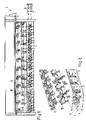
- the warp knitting machine 1 shows a warp knitting machine 1 with a machine bed 2 in a highly schematic form.
- the warp knitting machine 1 has several bars, not shown in detail, of which each bar carries knitting tools.
- the bars are suspended from levers 9, 10 driven by a drive assembly located in the machine bed 2.
- the bars have a longitudinal direction.
- the longitudinal direction corresponds to the width direction of the in 1 illustrated warp knitting machine 1, so the extension from left to right based on the representation of 1 .
- each drive ram 3-6 is connected to a drive motor 7,8.
- the drive motors 7, 8 are arranged at one end of the warp knitting machine 1.
- the drive motors 7 , 8 can also be arranged at both ends of the warp knitting machine 1 .
- the drive motors 7, 8 drive the drive rams 3-6 in a translatory manner, ie parallel to the width direction of the warp knitting machine 1 or in the longitudinal direction of the bars.
- each of the levers 9, 10 carrying a bar is connected via a plurality of lifting rams to the drive rams assigned to the respective bar.
- a lifting ram 11 is shown here, which connects a lever 9 to the drive ram 3 .
- the drive ram 3 is used here to generate a movement of a foundation bar
- the drive ram 4 is used to generate a movement of a slide bar
- the drive ram 5 is used to generate a movement of a comb bar
- the drive ram 6 is used to generate a movement of a needle bar.
- the drive ram 3 is moved back and forth in the direction of the double arrow 12 by the drive motor 7 .
- the lifting ram 11 on the other hand, must be moved in the direction of a double arrow 13 perpendicular to the first-mentioned direction (double arrow 12).
- the drive arrangement has a change of direction gear 14 which, in the present case, is designed as a “wedge gear” and has a wedge surface arrangement with a wedge surface 15 .
- the wedge surface arrangement has a wedge surface carrier 16 which has, for example, a cylindrical outer contour.
- the drive ram 3 is passed through a bore 17 in the wedge surface carrier 16 and fixed to the drive ram 3 by clamps 18 , 19 .
- the clamps 18, 19 can be released. This has several advantages.
- the wedge surface carrier 16 can be positioned relatively precisely on the drive ram 3 . This positioning can be changed, if desired, in order to change the performance of the warp knitting machine 1.
- the lifting ram 11 is provided with a guide 20 through which the wedge surface carrier 16 is guided.
- a recirculating ball guide 21 is provided between the guide 20 and the wedge surface carrier 16, so that the wedge surface carrier 16 and the guide 20 can interact with little friction.
- the lifting ram 11 is moved upwards over the wedge surface 15. In a corresponding manner, the lifting ram 11 is moved downwards when the driving ram 3 is moved to the left.
- the lifting ram 11 is provided with a spring arrangement 22 .
- the spring assembly 22 may be positioned on either side of the guide 20 as shown.
- the spring arrangement 22 serves as an energy store.
- the upper part of the spring assembly 22 is compressed when the lifting ram 11 moves up and relaxes when the lifting ram 11 is moved down.
- the lower part of the spring assembly 22 is compressed when the lift ram 11 moves down and relaxes when the lift ram 11 moves up.
- the directions refer to the representation of the 3 .
- a neutral position of the lifting ram 11 which corresponds to a neutral position of the bar driven by the lifting ram 11 , the spring arrangement 22 does not exert any forces on the lifting ram 11 . Provision can be made for only one half of the spring arrangement 22 to become effective when the lifting ram moves out of the neutral position in one direction. However, it can also be provided that the spring arrangement 22 becomes effective overall.
- the spring assembly 22 When a bar is raised from its neutral position, the spring assembly 22 is tensioned and so to speak stores tension energy. Tensioning can take place in that a compression spring is compressed. It is also possible that a tension spring is tensioned. When the bar has then reached its upper reversal point, the clamping energy is at its maximum. When the bar is then moved back down, the clamping energy, i.e. potential energy, is converted into kinetic energy. When passing through the neutral position, the clamping energy is minimal and the kinetic energy is maximal. With further movement of the bar, the spring arrangement 22 is tensioned in the opposite direction and thereby stores tensioning energy again. This clamping energy is in turn used to move the bar up. This cycle continues periodically. The energy supplied at the beginning is retained, so that you only have to compensate for losses that occur gradually in bearings due to friction and during the knitting process, in order to keep the bar permanently in the periodic movement.
- the spring arrangement 22 is dimensioned in such a way that it resonates at a predetermined working speed of the warp knitting machine 1 .
- the drive arrangement with the drive ram 3 and the drive motor 7 as well as the direction change gear 14 only has to apply relatively small forces, namely the forces necessary to overcome losses caused by friction and the like.
- the spring assembly 22 is shown here schematically as a helical spring.
- the spring arrangement 22 has a variable rigidity. It can thus be taken into account that the drive motor 7 does not have to additionally overcome the force of a very stiff spring arrangement 22 when the warp knitting machine is started up, ie when the working speed is increased. So you can make the stiffness of the spring assembly 22 smaller at low speeds than at higher speeds.
- the spring arrangement 22 it is preferable for the spring arrangement 22 to be designed with a gas spring.
- FIG. 4 shows a modified embodiment, in which the same elements are provided with the same reference numbers.
- the drive ram 3 no longer passes through the wedge surface carrier 16 , but the wedge surface carrier 16 is arranged above the drive ram 3 .
- the lifting ram 11 has an opening 23 through which the drive ram 3 is guided.
- the wedge surface carrier 18 is in turn fastened to the drive ram 3 with clamps 18 , 19 .
- the drive motor 7 is arranged on the other side of the drive ram 3 in this case, to show that the drive motors 7, 8 can be provided at both ends of the warp knitting machine 1.
- the wedge surface carrier 6 is arranged above the drive ram 3 . However, it can also be arranged below the drive plunger 3 .
- FIG. 5 now shows a detail of the warp knitting machine 1 with two drive rams 4, 5.
- the drive ram 4 is provided with a wedge surface 15', which is inclined from top left to bottom right, while the drive ram 5 is provided with a wedge surface 15'', which is provided from left down to the top right.
- Each drive ram 4, 5 acts on a lifting ram 11. However, these two lifting rams 11 are arranged one behind the other, so that only one lifting ram 11 can be seen. If the two lifting rams 11 are to be moved in the same way, for example both upwards, the drive ram 4 is moved in the direction of an arrow 24 from left to right and the drive ram 5 is moved in the direction of an arrow 25 from right to left.
- the two drive rams 4, 5 are therefore driven in opposite directions, so that the reaction forces resulting from the drive of the drive rams 4, 5 on the machine bed 2 can be at least partially compensated.
- the drive motors 7, 8 can be designed as linear drives.
- a rotary motor can be used, for example, which drives a spindle on which a non-rotatably held nut is arranged, which in turn is connected to the respective drive ram 3-6.
- the drive motor or motors 7, 8 can also be designed as rotary drives.
- a rotary motor can again be provided, which acts via an eccentric or another cam disk or via a connecting rod in the respective drive ram 3 .
- the drive rams 3-6 are moved translationally, namely parallel to the longitudinal direction of the bars, ie in the width direction of the warp knitting machine.
- the warp knitting machine 1 has its greatest rigidity in this direction.
Landscapes
- Engineering & Computer Science (AREA)
- Textile Engineering (AREA)
- Knitting Machines (AREA)
Description
- Die vorliegende Erfindung betrifft eine Kettenwirkmaschine nach dem Oberbegriff des Anspruchs 1.
- Eine derartige Kettenwirkmaschine ist beispielsweise aus
GB 1 133 027 A US 3 464 236 A bekannt. - In einer Kettenwirkmaschine arbeiten Wirkwerkzeuge zusammen, um Maschen einer Wirkware zu bilden. Zu den Wirkwerkzeugen gehören Wirknadeln, die auch als Arbeitsnadeln bezeichnet werden, und Legenadeln. Die Wirknadeln müssen daher in einem Maschinenbildungszyklus eine ansteigende und eine abfallende Bewegung durchführen. Die Legenadeln müssen Fäden einer Kette um die Wirknadeln herumführen. Dementsprechend werden sie in einem Maschenbildungszyklus parallel zur Längsrichtung in eine Richtung, dann quer zur Längsrichtung, parallel zur Längsrichtung in die entgegengesetzte Richtung und quer zur Längsrichtung wieder zurückbewegt. Die Bewegung der Legenadeln parallel zur Längsrichtung wird auch als "Versatzbewegung" bezeichnet.
- Damit gleichartige Wirkwerkzeuge gleichartige Bewegungen ausführen können, sind sie an Barren befestigt. Die Barren werden üblicherweise von einer Hauptwelle angetrieben. Die Hauptwelle weist mehrere Pleuelabschnitte auf, an denen Pleuelstangen angreifen, die über Hebelgestänge auf die Barren wirken.
- Es ist allerdings relativ schwierig, eine Hauptwelle, die im Betrieb wechselnden Belastungen ausgesetzt ist, so auszugestalten, dass ein schwingungsfreier Betrieb erzielt wird. Dementsprechend bilden Schwingungen im Betrieb der Kettenwirkmaschine ein Problem, das beispielsweise die Arbeitsgeschwindigkeit der Kettenwirkmaschine beschränken kann.
-
WO 92/13127 A1 -
EP 3 081 681 A1 zeigt eine Wirkwerkzeugbarre mit einem Korpus, der eine Wirkwerkzeugaufnahme aufweist. Im Korpus ist eine Tilgeranordnung vorgesehen, die eine Feder mit einer veränderbaren Steifigkeit aufweist. -
EP 3 159 43 A1 - Der Erfindung liegt die Aufgabe zugrunde, Schwingungsprobleme kleinzuhalten.
- Diese Aufgabe wird bei einer Kettenwirkmaschine der eingangs genannten Art durch die Merkmale des Anspruchs 1 gelöst.
- Man verzichtet also für diese Barre auf eine rotierende Hauptwelle und erzeugt die Bewegung der Barre durch eine translatorische Bewegung des Antriebsstößels. Diese Bewegung erfolgt parallel zu der betreffenden Barre. Das Richtungsänderungsgetriebe setzt nun diese Bewegung parallel zur Barre in eine Bewegung etwa senkrecht zur Barre um. Diese Bewegung wiederum kann über eine Hebelanordnung, die durchaus einer herkömmlichen Hebelanordnung entsprechen kann, auf die Barre übertragen werden. Bei dieser Konstruktion entstehen zwar auch Schwingungsbelastungen durch wechselnde Kräfte. Der Antriebsstößel muss hin und her bewegt werden. Diese Kräfte wirken aber in Längsrichtung der Barren und damit auch in der Richtung, in der die Kettenwirkmaschine ihre größte Erstreckung hat. In diese Richtung ist die Kettenwirkmaschine also wesentlich steifer als quer zur Längsrichtung. Auch dies ist eine Maßnahme, um Schwingungsprobleme kleinzuhalten.
- Das Richtungsänderungsgetriebe weist eine Keilflächenanordnung auf. Eine Keilflächenanordnung weist mindestens eine Keilfläche auf, die zur Längsrichtung der Barre geneigt ist. Wenn die Keilflächenanordnung parallel zur Längsrichtung bewegt wird, dann verlagert sie ein an der Keilflächenanordnung anliegendes Element quer zur Längsrichtung.
- Vorzugsweise weist die Keilflächenanordnung eine auf dem Antriebsstößel lösbar festgelegte Keilfläche auf. Die Keilfläche kann also parallel zur Längsrichtung auf dem Antriebsstößel verschoben werden, bis sie ihre vorbestimmte Position erreicht hat. In dieser Position kann die Keilfläche dann auf dem Antriebsstößel festgelegt werden, beispielsweise durch eine Klemme. Damit lassen sich auf einfache Weise durch eine Verschiebung der Keilfläche auf den Antriebsstößel in gewissen Grenzen auch Änderungen des Betriebsverhaltens der Kettenwirkmaschine erreichen. Beispielsweise können Bewegungen von einzelnen Barren früher oder später ausgelöst werden.
- Vorzugsweise ist die Keilfläche an einem im Querschnitt quer zur Längsrichtung runden Keilflächenträger ausgebildet. Der Keilflächenträger kann beispielsweise einen kreisrunden Querschnitt haben.
- Vorzugsweise weist das Richtungsänderungsgetriebe eine Kugelumlaufführung auf. Die Kugelumlaufführung hält eine Reibung klein, die zwischen der Keilfläche und einem von der Keilfläche angetriebenen Element auftritt.
- Bevorzugterweise ist die Barre über einen Hubstößel mit dem Richtungsänderungsgetriebe verbunden und der Antriebsstößel durchsetzt den Hubstößel oder der Hubstößel durchsetzt den Antriebsstößel. Der Hubstößel wirkt auf ein Hebelgestänge, das seinerseits wiederum die Bewegung der Barre verursacht. Der Begriff "Hubstößel" wird hier aus Gründen der Anschaulichkeit gewählt. Der Hubstößel wird in vielen Fällen eine Bewegung etwa parallel zur Schwerkraftrichtung ausführen. Dies ist aber nicht zwingend. Wenn der Hubstößel den Antriebsstößel durchsetzt oder der Antriebsstößel den Hubstößel, dann kann man einen durchgehenden Hubstößel und einen durchgehenden Antriebsstößel verwenden und trotzdem eine relativ gleichmäßige Kraftverteilung auf diese beiden Elemente erreichen.
- Vorzugsweise weist die Antriebsanordnung eine quer zur Längsrichtung wirkende Federanordnung auf. Die Federanordnung kann hier als "Energiespeicher" verwendet werden. Die Federanordnung wird bei einer Bewegung der Barre aus einer Neutralstellung heraus gespannt und entspannt sich wieder, wenn sich die Barre in die Neutralstellung zurückbewegt. Für eine Bewegung der Barre aus der Neutralstellung heraus in die andere Richtung kann das Gleiche gelten. Im Idealfall ist die Federanordnung auf die Bewegung der Barre und der entsprechenden Antriebsanordnung so abgestimmt, dass sie bei einer Nennarbeitsgeschwindigkeit in Resonanz gerät. In diesem Fall muss die Antriebsanordnung nur geringfügige Antriebskräfte aufbringen, nämlich Kräfte, die zum Ausgleich der Verluste durch Reibung und dergleichen notwendig sind. Wenn die Barre aus ihrer Ruhelage, die auch als Neutralstellung bezeichnet werden kann, beispielsweise nach oben ausgelenkt wird, muss Hubarbeit verrichtet werden und die Federanordnung wird gespannt. Die Barre besitzt nun Lageenergie und Spannenergie. Wenn die Barre an ihrem oberen Umkehrpunkt angekommen ist, ändert sie ihre Bewegungsrichtung und bewegt sich zurück. Dabei wandelt sich die Lageenergie und Spannenergie in kinetische Energie um, die beim Durchgang durch die Neutralstellung ihren größten Wert annimmt. Diese kinetische Energie wandelt sich bei weiterer Bewegung wieder in Spannenergie um, bis der untere Umkehrpunkt erreicht ist. Wenn sich die Barre dann wieder nach oben bewegt, wandelt sich die Spannenergie wieder in kinetische Energie um. Dieser Kreislauf setzt sich periodisch fort. Eine anfangs eingebrachte Energie bleibt weitgehend erhalten. Man muss lediglich Reibungsverluste, die in Lagern und beim Wirkvorgang entstehen, ausgleichen, um die Barre dauerhaft in Bewegung zu halten.
- Vorzugsweise weist die Federanordnung eine veränderbare Steifigkeit auf. Man kann dann die Steifigkeit der Federanordnung an verschiedene Betriebszustände anpassen. Beispielsweise kann man beim Anfahren der Kettenwirkmaschine die Federanordnung mit einer relativ geringen Steifigkeit betreiben, so dass die Antriebsanordnung nicht noch zusätzlich eine hohe Federkraft überwinden muss. Mit zunehmender Arbeitsgeschwindigkeit der Kettenwirkmaschine kann dann die Steifigkeit der Federanordnung vergrößert werden.
- Hierbei ist bevorzugt, dass die Federanordnung mindestens eine Gasfeder aufweist. Eine Gasfeder, die beispielsweise mit Druckluft oder einem anderen Gas betrieben werden kann, lässt sich die Steifigkeit der Federanordnung auf einfache Weise einstellen.
- Vorzugsweise weist die Antriebsanordnung mehrere Antriebsmotoren auf, die über Antriebsstößel jeweils auf verschiedene Barren wirken. Man kann also für jede Barre einen eigenen Antriebsmotor verwenden. Dies hat den zusätzlichen Vorteil, dass die Bewegungen der Barren nicht mehr alle durch eine Hauptwelle miteinander gekoppelt sind. Vielmehr kann jede Barre sozusagen einzeln angesteuert werden, so dass auch die Zusammenarbeit der Wirkwerkzeuge verändert werden kann. Beispielsweise kann man den Abschlag verändern, indem man die Abschlagplatine früher oder später in den Maschenbildungsvorgang eingreifen lässt. Damit ergeben sich neue Möglichkeiten für die Gestaltung von Wirkwaren.
- Vorzugsweise weist die Antriebsanordnung mindestens zwei Richtungsänderungsgetriebe mit jeweils einem Antriebsstößel auf, wobei die Antriebsstößel gegensinnig angetrieben sind. Die Antriebsstößel weisen dann Keilflächenanordnungen mit entgegengesetzten Neigungen auf. Wenn zwei Antriebsstößel gegensinnig zueinander angetrieben sind, dann erzeugen sie auch gegensinnig gerichtete Reaktionskräfte, die auf das Maschinenbett der Kettenwirkmaschine wirken. Diese entgegengesetzt gerichteten Reaktionskräfte können sich dann zumindest teilweise ausgleichen, so dass die Summe der auf das Maschinenbett wirkenden Kräfte klein gehalten werden kann und entsprechend eine Schwingungsanregung ebenfalls klein gehalten werden kann.
- Vorzugsweise sind Antriebsmotoren der Antriebsstößel an in Längsrichtung gegenüberliegenden Enden der Kettenwirkmaschine angeordnet. Damit nutzt man den zur Verfügung stehenden Bauraum gut aus.
- Vorzugsweise ist mindestens ein Antriebsmotor als Linearantrieb ausgebildet. Ein Linearantrieb kann beispielsweise einen Rotationsmotor aufweisen, der über eine Schraubspindel auf eine Mutter wirkt, die ihrerseits den Antriebsstößel antreibt. Mit einem derartigen Linearantrieb lassen sich auf einfache Weise Bewegungen des Antriebsstößels sehr genau steuern.
- Alternativ oder zusätzlich kann vorgesehen sein, dass mindestens ein Antriebsmotor als Rotationsantrieb ausgebildet ist. Der Rotationsantrieb kann beispielsweise über einen Topfexzenter, eine Kurvenscheibe oder ein Pleuel angetrieben sein.
- Die Erfindung wird im Folgenden anhand von bevorzugten Ausführungsbeispielen in Verbindung mit der Zeichnung beschrieben. Hierin zeigen:
- Fig. 1
- eine schematische Darstellung einer Kettenwirkmaschine in Vorderansicht,
- Fig. 2
- eine perspektivische Ansicht eines Maschinenbetts einer Kettenwirkmaschine,
- Fig. 3
- eine erste Ausführungsform eines Richtungsänderungsgetriebes,
- Fig. 4
- eine zweite Ausführungsform eines Richtungsänderungsgetriebes und
- Fig. 5
- eine Ausgestaltung mit zwei Antriebsstößeln.
-
Fig. 1 zeigt in stark schematisierter Form eine Kettenwirkmaschine 1 mit einem Maschinenbett 2. Die Kettenwirkmaschine 1 weist mehrere nicht näher dargestellte Barren auf, von denen jede Barre Wirkwerkzeuge trägt. Die Barren sind an Hebeln 9, 10 aufgehängt, die von einer Antriebsanordnung angetrieben werden, die im Maschinenbett 2 angeordnet ist. - Die Barren weisen eine Längsrichtung auf. Die Längsrichtung entspricht der Breitenrichtung der in
Fig. 1 dargestellten Kettenwirkmaschine 1, also der Erstreckung von links nach rechts bezogen auf die Darstellung derFig. 1 . -
Fig. 2 zeigt in einer etwas vergrößerten Darstellung das Maschinenbett 2 mit mehreren Antriebsstößeln 3-6. Jeder Antriebsstößel 3-6 steht mit einem Antriebsmotor 7, 8 in Verbindung. Bei der Darstellung derFig. 1 sind die Antriebsmotoren 7, 8 an einem Ende der Kettenwirkmaschine 1 angeordnet. Man kann die Antriebsmotoren 7, 8 jedoch auch an beiden Enden der Kettenwirkmaschine 1 anordnen. - Die Antriebsmotoren 7, 8 treiben die Antriebsstößel 3-6 translatorisch an, also parallel zur Breitenrichtung der Kettenwirkmaschine 1 oder in Längsrichtung der Barren.
- Im Betrieb der Kettenwirkmaschine 1 müssen die Hebel 9, 10 der Kettenwirkmaschine 1 verschwenkt werden. Zu diesem Zweck sind die jeweils eine Barre tragenden Hebel 9, 10 über jeweils mehrere Hubstößel mit der der jeweiligen Barre zugeordneten Antriebsstößeln verbunden. Dies soll anhand von
Fig. 3 näher erläutert werden. Hier ist ein Hubstößel 11 dargestellt, der einen Hebel 9 mit dem Antriebsstößel 3 verbindet. Der Antriebsstößel 3 dient hier zum Erzeugen einer Bewegung einer Grundlegebarre, der Antriebsstößel 4 dient zum Erzeugen einer Bewegung einer Schieberbarre, der Antriebsstößel 5 dient zum Erzeugen einer Bewegung einer Stechkammbarre und der Antriebsstößel 6 dient zum Erzeugen einer Bewegung einer Nadelbarre. - Der Antriebsstößel 3 wird durch den Antriebsmotor 7 in Richtung des Doppelpfeils 12 hin und her bewegt. Der Hubstößel 11 muss hingegen in Richtung eines Doppelpfeils 13 senkrecht zu der erstgenannten Richtung (Doppelpfeil 12) bewegt werden. Hierzu weist die Antriebsanordnung ein Richtungsänderungsgetriebe 14 auf, das im vorliegenden Fall als "Keilgetriebe" ausgebildet ist und eine Keilflächenanordnung mit einer Keilfläche 15 aufweist. Die Keilflächenanordnung weist einen Keilflächenträger 16 auf, der beispielsweise eine zylinderförmige Außenkontur aufweist. Der Antriebsstößel 3 ist durch eine Bohrung 17 des Keilflächenträgers 16 geführt und durch Klemmen 18, 19 auf dem Antriebsstößel 3 fixiert. Die Klemmen 18, 19 können gelöst werden. Dies hat mehrere Vorteile. Zum einen ist es relativ einfach, den Antriebsstößel 3 mit dem Keilflächenträger 16 zu versehen. Zum anderen kann der Keilflächenträger 16 relativ genau auf dem Antriebsstößel 3 positioniert werden. Diese Positionierung kann, wenn gewünscht, verändert werden, um das Betriebsverhalten der Kettenwirkmaschine 1 zu ändern.
- Der Hubstößel 11 ist mit einer Führung 20 versehen, durch die der Keilflächenträger 16 hindurchgeführt ist. Zwischen der Führung 20 und dem Keilflächenträger 16 ist eine Kugelumlaufführung 21 vorgesehen, so dass der Keilflächenträger 16 und die Führung 20 reibungsarm zusammenwirken können.
- Wenn der Antriebsstößel 3 nach rechts bewegt wird (bezogen auf die Darstellung der
Fig. 3 ), dann wird der Hubstößel 11 über die Keilfläche 15 nach oben bewegt. In entsprechender Weise wird der Hubstößel 11 nach unten bewegt, wenn der Antriebsstößel 3 nach links bewegt wird. - Schematisch dargestellt ist, dass der Hubstößel 11 mit einer Federanordnung 22 versehen ist. Die Federanordnung 22 kann, wie dargestellt, auf beiden Seiten der Führung 20 angeordnet sein. Die Federanordnung 22 dient als Energiespeicher. Der obere Teil der Federanordnung 22 wird komprimiert, wenn sich der Hubstößel 11 nach oben bewegt und entspannt sich, wenn der Hubstößel 11 nach unten bewegt wird. Der untere Teil der Federanordnung 22 wird komprimiert, wenn sich der Hubstößel 11 nach unten bewegt und entspannt sich, wenn der Hubstößel 11 nach oben bewegt wird. Die Richtungsangaben beziehen sich auf die Darstellung der
Fig. 3 . In einer Neutralstellung des Hubstößels 11, der mit einer Neutralstellung der vom Hubstößel 11 angetriebenen Barre übereinstimmt, übt die Federanordnung 22 keine Kräfte auf den Hubstößel 11 aus. Man kann vorsehen, dass bei einer Bewegung des Hubstößels aus der Neutralstellung heraus in eine Richtung jeweils nur eine Hälfte der Federanordnung 22 wirksam wird. Man kann aber auch vorsehen, dass die Federanordnung 22 insgesamt wirksam wird. - Wenn eine Barre aus ihrer Neutralstellung angehoben wird, wird die Federanordnung 22 gespannt und speichert sozusagen Spannenergie. Das spannen kann dadurch erfolgen, dass eine Druckfeder komprimiert wird. Es ist auch möglich, dass eine Zugfeder gespannt wird. Wenn die Barre dann ihren oberen Umkehrpunkt erreicht hat, ist die Spannenergie maximal. Wenn die Barre danach wieder nach unten bewegt wird, wird die Spannenergie, also eine potentielle Energie, in kinetische Energie umgewandelt. Beim Durchgang durch die Neutralstellung ist die Spannenergie minimal und die kinetische Energie maximal. Bei weiterer Bewegung der Barre wird die Federanordnung 22 in entgegengesetzte Richtung gespannt und speichert dadurch wieder Spannenergie. Diese Spannenergie wird wiederum verwendet, um die Barre nach oben zu bewegen. Dieser Kreislauf setzt sich periodisch fort. Die anfangs zugeführte Energie bleibt erhalten, so das man nur Verluste ausgleichen muss, die bei schrittweise in Lagern durch Reibung und beim Wirkvorgang entstehen, ausgleichen muss, um die Barre dauerhaft in der periodischen Bewegung zu halten.
- Im Idealfall ist die Federanordnung 22 so dimensioniert, dass sie bei einer vorbestimmten Arbeitsgeschwindigkeit der Kettenwirkmaschine 1 in Resonanz gerät. In diesem Fall muss die Antriebsanordnung mit dem Antriebsstößel 3 und dem Antriebsmotor 7 sowie dem Richtungsänderungsgetriebe 14 nur relativ geringe Kräfte aufbringen, nämlich die Kräfte, die zur Überwindung von Verlusten notwendig sind, die durch Reibung und dergleichen verursacht werden.
- Die Federanordnung 22 ist hier schematisch als Schraubenfeder dargestellt. Man kann nun vorzugsweise vorsehen, dass die Federanordnung 22eine veränderbare Steifigkeit aufweist. Damit kann man berücksichtigen, dass der Antriebsmotor 7 beim Hochfahren der Kettenwirkmaschine, also beim Steigern der Arbeitsgeschwindigkeit, nicht noch zusätzlich die Kraft einer sehr steifen Federanordnung 22 überwinden muss. Man kann also bei niedrigen Drehzahlen die Steifigkeit der Federanordnung 22 kleiner machen als bei höheren Drehzahlen.
- Hierzu ist bevorzugt, dass man die Federanordnung 22 mit einer Gasfeder ausbildet.
-
Fig. 4 zeigt eine abgewandelte Ausführungsform, bei der gleiche Elemente mit den gleichen Bezugszeichen versehen sind. Bei der Ausgestaltung nachFig. 4 durchsetzt der Antriebsstößel 3 nicht mehr den Keilflächenträger 16, sondern der Keilflächenträger 16 ist oberhalb des Antriebsstößels 3 angeordnet. Der Hubstößel 11 weist eine Durchbrechung 23 auf, durch die der Antriebsstößel 3 hindurchgeführt ist. Der Keilflächenträger 18 ist wiederum mit Klemmen 18, 19 an dem Antriebsstößel 3 befestigt. - Der Antriebsmotor 7 ist in diesem Fall an der anderen Seite des Antriebsstößels 3 angeordnet, um darzustellen, dass die Antriebsmotoren 7, 8 an beiden Enden der Kettenwirkmaschine 1 vorgesehen sein können.
- In
Fig. 4 ist der Keilflächenträger 6 oberhalb des Antriebsstößels 3 angeordnet. Er kann jedoch auch unterhalb des Antriebsstößels 3 angeordnet sein. -
Fig. 5 zeigt nun einen Ausschnitt der Kettenwirkmaschine 1 mit zwei Antriebsstößeln 4, 5. Der Antriebsstößel 4 ist mit einer Keilfläche 15' versehen, die von links oben nach rechts unten geneigt ist, während der Antriebsstößel 5 mit einer Keilfläche 15" versehen ist, die von links unten nach rechts oben geneigt ist. - Jeder Antriebsstößel 4, 5 wirkt auf einen Hubstößel 11. Diese beiden Hubstößel 11 sind allerdings hintereinander angeordnet, so dass man nur einen Hubstößel 11 erkennen kann. Wenn die beiden Hubstößel 11 gleichartig bewegt werden sollen, also beispielsweise beide nach oben, wird der Antriebsstößel 4 in Richtung eines Pfeiles 24 von links nach rechts bewegt und der Antriebsstößel 5 wird in Richtung eines Pfeils 25 von rechts nach links bewegt.
- Die beiden Antriebsstößel 4, 5 werden also gegensinnig angetrieben, so dass sich die durch den Antrieb der Antriebsstößel 4, 5 auf das Maschinenbett 2 ergebenden Reaktionskräfte zumindest teilweise ausgleichen können.
- Die Antriebsmotoren 7, 8 können als Linearantriebe ausgebildet sein. Bei einem Linearantrieb kann man beispielsweise einen Rotationsmotor verwenden, der eine Spindel antreibt, auf der eine drehfest gehaltene Mutter angeordnet ist, die wiederum mit dem jeweiligen Antriebsstößel 3-6 verbunden ist.
- Man kann den oder die Antriebsmotoren 7, 8 auch als Rotationsantriebe ausbilden. In diesem Fall kann wiederum ein Rotationsmotor vorgesehen sein, der über einen Exzenter oder eine andere Kurvenscheibe oder über einen Pleuel im jeweiligen Antriebsstößel 3 wirkt.
- In jedem Fall werden die Antriebsstößel 3-6 translatorisch bewegt und zwar parallel zur Längsrichtung der Barren, also in Breitenrichtung der Kettenwirkmaschine. In dieser Richtung hat die Kettenwirkmaschine 1 ihre größte Steifigkeit.
Claims (13)
- Kettenwirkmaschine (1) mit mehreren Barren, die jeweils eine Längsrichtung aufweisen, und einer auf die Barren quer zur Längsrichtung wirkenden Antriebsanordnung, die mindestens einen Antriebsmotor (7, 8) aufweist, wobei die Antriebsanordnung mindestens einen durch den Antriebsmotor (7, 8) in Längsrichtung bewegbaren Antriebsstößel (3-6) aufweist, der über ein Richtungsänderungsgetriebe (14) auf mindestens eine Barre wirkt, dadurch gekennzeichnet, dass das Richtungsänderungsgetriebe (14) eine Keilflächenanordnung aufweist.
- Kettenwirkmaschine nach Anspruch 1, dadurch gekennzeichnet, dass die Keilflächenanordnung eine auf dem Antriebsstößel (3-6) lösbar festgelegte Keilfläche (15) aufweist.
- Kettenwirkmaschine nach Anspruch 2, dadurch gekennzeichnet, dass die Keilfläche (15) an einem im Querschnitt quer zur Längsrichtung runden Keilflächenträger (16) ausgebildet ist
- Kettenwirkmaschine nach einem der Ansprüche 1 bis 3, dadurch gekennzeichnet, dass das Richtungsänderungsgetriebe (14) eine Kugelumlaufführung (21) aufweist.
- Kettenwirkmaschine nach einem der Ansprüche 1 bis 4, dadurch gekennzeichnet, dass die Barre, auf die das Richtungsänderungsgetriebe wirkt, über einen Hubstößel (11) mit dem Richtungsänderungsgetriebe (14) verbunden ist und der Antriebsstößel (3-6) den Hubstößel (11) oder der Hubstößel (11) den Antriebsstößel (3-6) durchsetzt.
- Kettenwirkmaschine nach einem der Ansprüche 1 bis 5, dadurch gekennzeichnet, dass die Antriebsanordnung eine quer zur Längsrichtung wirkende Federanordnung (22) aufweist.
- Kettenwirkmaschine nach Anspruch 6, dadurch gekennzeichnet, dass die Federanordnung (22) eine veränderbare Steifigkeit aufweist.
- Kettenwirkmaschine nach Anspruch 6 oder 7, dadurch gekennzeichnet, dass die Federanordnung (22) mindestens eine Gasfeder aufweist.
- Kettenwirkmaschine nach einem der Ansprüche 1 bis 8, dadurch gekennzeichnet, dass die Antriebsanordnung mehrere Antriebsmotoren (7, 8) aufweist, die über Antriebsstößel (3-6) jeweils auf verschiedene Barren wirken.
- Kettenwirkmaschine nach einem der Ansprüche 1 bis 9, dadurch gekennzeichnet, dass die Antriebsanordnung mindestens zwei Richtungsänderungsgetriebe (14) mit jeweils einem Antriebsstößel (4, 5) aufweist, wobei die Antriebsstößel (4, 5) gegensinnig angetrieben sind.
- Kettenwirkmaschine nach einem der Ansprüche 1 bis 10, dadurch gekennzeichnet, dass Antriebsmotoren (7, 8) der Antriebsstößel (3-6) an in Längsrichtung gegenüberliegenden Enden der Kettenwirkmaschine (1) angeordnet sind.
- Kettenwirkmaschine nach einem der Ansprüche 1 bis 11, dadurch gekennzeichnet, dass mindestens ein Antriebsmotor (7, 8) als Linearantrieb ausgebildet ist.
- Kettenwirkmaschine nach einem der Ansprüche 1 bis 12, dadurch gekennzeichnet, dass mindestens ein Antriebsmotor (7, 8) als Rotationsantrieb ausgebildet ist.
Priority Applications (2)
| Application Number | Priority Date | Filing Date | Title |
|---|---|---|---|
| EP20182789.6A EP3933084B1 (de) | 2020-06-29 | 2020-06-29 | Kettenwirkmaschine mit einem richtungsänderungsgetriebe |
| CN202110093289.6A CN113930892B (zh) | 2020-06-29 | 2021-01-25 | 经编机 |
Applications Claiming Priority (1)
| Application Number | Priority Date | Filing Date | Title |
|---|---|---|---|
| EP20182789.6A EP3933084B1 (de) | 2020-06-29 | 2020-06-29 | Kettenwirkmaschine mit einem richtungsänderungsgetriebe |
Publications (2)
| Publication Number | Publication Date |
|---|---|
| EP3933084A1 EP3933084A1 (de) | 2022-01-05 |
| EP3933084B1 true EP3933084B1 (de) | 2022-06-22 |
Family
ID=71266451
Family Applications (1)
| Application Number | Title | Priority Date | Filing Date |
|---|---|---|---|
| EP20182789.6A Active EP3933084B1 (de) | 2020-06-29 | 2020-06-29 | Kettenwirkmaschine mit einem richtungsänderungsgetriebe |
Country Status (2)
| Country | Link |
|---|---|
| EP (1) | EP3933084B1 (de) |
| CN (1) | CN113930892B (de) |
Family Cites Families (6)
| Publication number | Priority date | Publication date | Assignee | Title |
|---|---|---|---|---|
| GB1133027A (en) * | 1966-06-14 | 1968-11-06 | Mayer Textilmaschf | Improvements in and relating to raschel knitting machines |
| US3464236A (en) * | 1968-01-31 | 1969-09-02 | Bassist Rudolf G | Knitting machine employing compensating motion for knitting effect thread |
| DE4113953A1 (de) * | 1991-01-24 | 1992-07-30 | Textilma Ag | Kettenwirkmaschine, insbesondere haekelgallonmaschine |
| JP3856068B2 (ja) * | 1998-11-16 | 2006-12-13 | Ykk株式会社 | 細幅クロッシェ編機における複合編針の作動機構 |
| EP3081681B1 (de) * | 2015-04-15 | 2017-03-22 | Karl Mayer Textilmaschinenfabrik GmbH | Wirkwerkzeugbarre |
| EP3159443B1 (de) * | 2015-10-23 | 2023-07-19 | KARL MAYER STOLL R&D GmbH | Kettenwirkmaschine |
-
2020
- 2020-06-29 EP EP20182789.6A patent/EP3933084B1/de active Active
-
2021
- 2021-01-25 CN CN202110093289.6A patent/CN113930892B/zh not_active Expired - Fee Related
Also Published As
| Publication number | Publication date |
|---|---|
| EP3933084A1 (de) | 2022-01-05 |
| CN113930892A (zh) | 2022-01-14 |
| CN113930892B (zh) | 2024-05-17 |
Similar Documents
| Publication | Publication Date | Title |
|---|---|---|
| DE2609411C3 (de) | Vorrichtung zum Steuern der flexiblen Greiferbänder einer Webmaschine | |
| DE681181C (de) | Kettenwirkmaschine | |
| DE19615671C2 (de) | Vorrichtung zur Herstellung von Kettenwirkware mit zwei voneinander unabhängigen Wirkbereichen | |
| EP1526201B1 (de) | Kettenwirkmaschine | |
| DE4017620C2 (de) | ||
| EP3299501B1 (de) | Kettenwirkmaschine | |
| CH660383A5 (de) | Flachstrickmaschine. | |
| EP0522100A1 (de) | Kettenwirkmaschine, insbesondere häkelgallonmaschine. | |
| DE2933841A1 (de) | Einrichtung fuer eine maschine fuer die herstellung flaechenhafter textilien, mit einem um eine schwenkachse schwenkbaren fadenfuehrer oder fadenumlenkorgan und verfahren zum betrieb der einrichtung | |
| DD286005A5 (de) | Haekelgalonmaschine | |
| EP3933084A1 (de) | Kettenwirkmaschine | |
| DE10321331B4 (de) | Wirkmaschine | |
| DE9306474U1 (de) | Wirkmaschine, insbesondere Häkelgalonmaschine | |
| DE3346246C2 (de) | Kettenwirkmaschine, insbesondere Häkelgalonmaschine | |
| EP3859067B1 (de) | Kettenwirkmaschine | |
| DE19638392B4 (de) | Kettenwirkmaschine | |
| DD148352A5 (de) | Kuliereinrichtung fuer flachstrickmaschinen | |
| EP4095297B1 (de) | Platine, strickvorrichtung und strickverfahren zum erzeugen von maschenwaren | |
| DD242645A5 (de) | Kettelmaschine | |
| DE19519410C2 (de) | Polbildende Kettenwirkmaschine | |
| DE2055300C3 (de) | Vorrichtung zum Antrieb der Faden fuhrer einer mehrfontungen Strickma schme mit jeweils V förmig angeordneten Nadelbetten | |
| DE102006026979B4 (de) | Kettenwirkmaschine | |
| EP4151790B1 (de) | Legebarrenantrieb einer kettenwirkmaschine | |
| DE1246928B (de) | Strickmaschine, bei der jede Nadel ueber einen hydraulischen Schubkolben bewegbar ist | |
| EP3216903A1 (de) | Kettenwirkmaschine |
Legal Events
| Date | Code | Title | Description |
|---|---|---|---|
| PUAI | Public reference made under article 153(3) epc to a published international application that has entered the european phase |
Free format text: ORIGINAL CODE: 0009012 |
|
| STAA | Information on the status of an ep patent application or granted ep patent |
Free format text: STATUS: REQUEST FOR EXAMINATION WAS MADE |
|
| 17P | Request for examination filed |
Effective date: 20210601 |
|
| AK | Designated contracting states |
Kind code of ref document: A1 Designated state(s): AL AT BE BG CH CY CZ DE DK EE ES FI FR GB GR HR HU IE IS IT LI LT LU LV MC MK MT NL NO PL PT RO RS SE SI SK SM TR |
|
| B565 | Issuance of search results under rule 164(2) epc |
Effective date: 20201218 |
|
| REG | Reference to a national code |
Ref country code: DE Ref legal event code: R079 Ref document number: 502020001257 Country of ref document: DE Free format text: PREVIOUS MAIN CLASS: D04B0027080000 Ipc: D04B0027260000 |
|
| GRAP | Despatch of communication of intention to grant a patent |
Free format text: ORIGINAL CODE: EPIDOSNIGR1 |
|
| STAA | Information on the status of an ep patent application or granted ep patent |
Free format text: STATUS: GRANT OF PATENT IS INTENDED |
|
| RIC1 | Information provided on ipc code assigned before grant |
Ipc: D04B 27/08 20060101ALI20220318BHEP Ipc: D04B 27/26 20060101AFI20220318BHEP |
|
| INTG | Intention to grant announced |
Effective date: 20220406 |
|
| GRAS | Grant fee paid |
Free format text: ORIGINAL CODE: EPIDOSNIGR3 |
|
| GRAA | (expected) grant |
Free format text: ORIGINAL CODE: 0009210 |
|
| STAA | Information on the status of an ep patent application or granted ep patent |
Free format text: STATUS: THE PATENT HAS BEEN GRANTED |
|
| AK | Designated contracting states |
Kind code of ref document: B1 Designated state(s): AL AT BE BG CH CY CZ DE DK EE ES FI FR GB GR HR HU IE IS IT LI LT LU LV MC MK MT NL NO PL PT RO RS SE SI SK SM TR |
|
| REG | Reference to a national code |
Ref country code: GB Ref legal event code: FG4D Free format text: NOT ENGLISH |
|
| REG | Reference to a national code |
Ref country code: CH Ref legal event code: EP |
|
| REG | Reference to a national code |
Ref country code: DE Ref legal event code: R096 Ref document number: 502020001257 Country of ref document: DE |
|
| REG | Reference to a national code |
Ref country code: AT Ref legal event code: REF Ref document number: 1499830 Country of ref document: AT Kind code of ref document: T Effective date: 20220715 |
|
| REG | Reference to a national code |
Ref country code: IE Ref legal event code: FG4D Free format text: LANGUAGE OF EP DOCUMENT: GERMAN |
|
| REG | Reference to a national code |
Ref country code: LT Ref legal event code: MG9D |
|
| REG | Reference to a national code |
Ref country code: NL Ref legal event code: MP Effective date: 20220622 |
|
| PG25 | Lapsed in a contracting state [announced via postgrant information from national office to epo] |
Ref country code: SE Free format text: LAPSE BECAUSE OF FAILURE TO SUBMIT A TRANSLATION OF THE DESCRIPTION OR TO PAY THE FEE WITHIN THE PRESCRIBED TIME-LIMIT Effective date: 20220622 Ref country code: NO Free format text: LAPSE BECAUSE OF FAILURE TO SUBMIT A TRANSLATION OF THE DESCRIPTION OR TO PAY THE FEE WITHIN THE PRESCRIBED TIME-LIMIT Effective date: 20220922 Ref country code: LT Free format text: LAPSE BECAUSE OF FAILURE TO SUBMIT A TRANSLATION OF THE DESCRIPTION OR TO PAY THE FEE WITHIN THE PRESCRIBED TIME-LIMIT Effective date: 20220622 Ref country code: HR Free format text: LAPSE BECAUSE OF FAILURE TO SUBMIT A TRANSLATION OF THE DESCRIPTION OR TO PAY THE FEE WITHIN THE PRESCRIBED TIME-LIMIT Effective date: 20220622 Ref country code: GR Free format text: LAPSE BECAUSE OF FAILURE TO SUBMIT A TRANSLATION OF THE DESCRIPTION OR TO PAY THE FEE WITHIN THE PRESCRIBED TIME-LIMIT Effective date: 20220923 Ref country code: FI Free format text: LAPSE BECAUSE OF FAILURE TO SUBMIT A TRANSLATION OF THE DESCRIPTION OR TO PAY THE FEE WITHIN THE PRESCRIBED TIME-LIMIT Effective date: 20220622 Ref country code: BG Free format text: LAPSE BECAUSE OF FAILURE TO SUBMIT A TRANSLATION OF THE DESCRIPTION OR TO PAY THE FEE WITHIN THE PRESCRIBED TIME-LIMIT Effective date: 20220922 |
|
| PG25 | Lapsed in a contracting state [announced via postgrant information from national office to epo] |
Ref country code: RS Free format text: LAPSE BECAUSE OF FAILURE TO SUBMIT A TRANSLATION OF THE DESCRIPTION OR TO PAY THE FEE WITHIN THE PRESCRIBED TIME-LIMIT Effective date: 20220622 Ref country code: LV Free format text: LAPSE BECAUSE OF FAILURE TO SUBMIT A TRANSLATION OF THE DESCRIPTION OR TO PAY THE FEE WITHIN THE PRESCRIBED TIME-LIMIT Effective date: 20220622 |
|
| PG25 | Lapsed in a contracting state [announced via postgrant information from national office to epo] |
Ref country code: NL Free format text: LAPSE BECAUSE OF FAILURE TO SUBMIT A TRANSLATION OF THE DESCRIPTION OR TO PAY THE FEE WITHIN THE PRESCRIBED TIME-LIMIT Effective date: 20220622 |
|
| PG25 | Lapsed in a contracting state [announced via postgrant information from national office to epo] |
Ref country code: SM Free format text: LAPSE BECAUSE OF FAILURE TO SUBMIT A TRANSLATION OF THE DESCRIPTION OR TO PAY THE FEE WITHIN THE PRESCRIBED TIME-LIMIT Effective date: 20220622 Ref country code: SK Free format text: LAPSE BECAUSE OF FAILURE TO SUBMIT A TRANSLATION OF THE DESCRIPTION OR TO PAY THE FEE WITHIN THE PRESCRIBED TIME-LIMIT Effective date: 20220622 Ref country code: RO Free format text: LAPSE BECAUSE OF FAILURE TO SUBMIT A TRANSLATION OF THE DESCRIPTION OR TO PAY THE FEE WITHIN THE PRESCRIBED TIME-LIMIT Effective date: 20220622 Ref country code: PT Free format text: LAPSE BECAUSE OF FAILURE TO SUBMIT A TRANSLATION OF THE DESCRIPTION OR TO PAY THE FEE WITHIN THE PRESCRIBED TIME-LIMIT Effective date: 20221024 Ref country code: ES Free format text: LAPSE BECAUSE OF FAILURE TO SUBMIT A TRANSLATION OF THE DESCRIPTION OR TO PAY THE FEE WITHIN THE PRESCRIBED TIME-LIMIT Effective date: 20220622 Ref country code: EE Free format text: LAPSE BECAUSE OF FAILURE TO SUBMIT A TRANSLATION OF THE DESCRIPTION OR TO PAY THE FEE WITHIN THE PRESCRIBED TIME-LIMIT Effective date: 20220622 Ref country code: CZ Free format text: LAPSE BECAUSE OF FAILURE TO SUBMIT A TRANSLATION OF THE DESCRIPTION OR TO PAY THE FEE WITHIN THE PRESCRIBED TIME-LIMIT Effective date: 20220622 |
|
| REG | Reference to a national code |
Ref country code: BE Ref legal event code: MM Effective date: 20220630 |
|
| PG25 | Lapsed in a contracting state [announced via postgrant information from national office to epo] |
Ref country code: PL Free format text: LAPSE BECAUSE OF FAILURE TO SUBMIT A TRANSLATION OF THE DESCRIPTION OR TO PAY THE FEE WITHIN THE PRESCRIBED TIME-LIMIT Effective date: 20220622 Ref country code: IS Free format text: LAPSE BECAUSE OF FAILURE TO SUBMIT A TRANSLATION OF THE DESCRIPTION OR TO PAY THE FEE WITHIN THE PRESCRIBED TIME-LIMIT Effective date: 20221022 |
|
| REG | Reference to a national code |
Ref country code: DE Ref legal event code: R097 Ref document number: 502020001257 Country of ref document: DE |
|
| PG25 | Lapsed in a contracting state [announced via postgrant information from national office to epo] |
Ref country code: MC Free format text: LAPSE BECAUSE OF FAILURE TO SUBMIT A TRANSLATION OF THE DESCRIPTION OR TO PAY THE FEE WITHIN THE PRESCRIBED TIME-LIMIT Effective date: 20220622 Ref country code: AL Free format text: LAPSE BECAUSE OF FAILURE TO SUBMIT A TRANSLATION OF THE DESCRIPTION OR TO PAY THE FEE WITHIN THE PRESCRIBED TIME-LIMIT Effective date: 20220622 |
|
| PG25 | Lapsed in a contracting state [announced via postgrant information from national office to epo] |
Ref country code: LU Free format text: LAPSE BECAUSE OF NON-PAYMENT OF DUE FEES Effective date: 20220629 Ref country code: IE Free format text: LAPSE BECAUSE OF NON-PAYMENT OF DUE FEES Effective date: 20220629 Ref country code: DK Free format text: LAPSE BECAUSE OF FAILURE TO SUBMIT A TRANSLATION OF THE DESCRIPTION OR TO PAY THE FEE WITHIN THE PRESCRIBED TIME-LIMIT Effective date: 20220622 |
|
| PLBE | No opposition filed within time limit |
Free format text: ORIGINAL CODE: 0009261 |
|
| STAA | Information on the status of an ep patent application or granted ep patent |
Free format text: STATUS: NO OPPOSITION FILED WITHIN TIME LIMIT |
|
| 26N | No opposition filed |
Effective date: 20230323 |
|
| PG25 | Lapsed in a contracting state [announced via postgrant information from national office to epo] |
Ref country code: BE Free format text: LAPSE BECAUSE OF NON-PAYMENT OF DUE FEES Effective date: 20220630 |
|
| PG25 | Lapsed in a contracting state [announced via postgrant information from national office to epo] |
Ref country code: FR Free format text: LAPSE BECAUSE OF NON-PAYMENT OF DUE FEES Effective date: 20220822 |
|
| P01 | Opt-out of the competence of the unified patent court (upc) registered |
Effective date: 20230705 |
|
| REG | Reference to a national code |
Ref country code: CH Ref legal event code: PL |
|
| PG25 | Lapsed in a contracting state [announced via postgrant information from national office to epo] |
Ref country code: MK Free format text: LAPSE BECAUSE OF FAILURE TO SUBMIT A TRANSLATION OF THE DESCRIPTION OR TO PAY THE FEE WITHIN THE PRESCRIBED TIME-LIMIT Effective date: 20220622 Ref country code: CY Free format text: LAPSE BECAUSE OF FAILURE TO SUBMIT A TRANSLATION OF THE DESCRIPTION OR TO PAY THE FEE WITHIN THE PRESCRIBED TIME-LIMIT Effective date: 20220622 Ref country code: CH Free format text: LAPSE BECAUSE OF NON-PAYMENT OF DUE FEES Effective date: 20230630 |
|
| PG25 | Lapsed in a contracting state [announced via postgrant information from national office to epo] |
Ref country code: HU Free format text: LAPSE BECAUSE OF FAILURE TO SUBMIT A TRANSLATION OF THE DESCRIPTION OR TO PAY THE FEE WITHIN THE PRESCRIBED TIME-LIMIT; INVALID AB INITIO Effective date: 20200629 |
|
| PGFP | Annual fee paid to national office [announced via postgrant information from national office to epo] |
Ref country code: DE Payment date: 20240627 Year of fee payment: 5 |
|
| PG25 | Lapsed in a contracting state [announced via postgrant information from national office to epo] |
Ref country code: MT Free format text: LAPSE BECAUSE OF FAILURE TO SUBMIT A TRANSLATION OF THE DESCRIPTION OR TO PAY THE FEE WITHIN THE PRESCRIBED TIME-LIMIT Effective date: 20220622 |
|
| PGFP | Annual fee paid to national office [announced via postgrant information from national office to epo] |
Ref country code: IT Payment date: 20240619 Year of fee payment: 5 |
|
| PG25 | Lapsed in a contracting state [announced via postgrant information from national office to epo] |
Ref country code: BG Free format text: LAPSE BECAUSE OF FAILURE TO SUBMIT A TRANSLATION OF THE DESCRIPTION OR TO PAY THE FEE WITHIN THE PRESCRIBED TIME-LIMIT Effective date: 20220622 |
|
| PG25 | Lapsed in a contracting state [announced via postgrant information from national office to epo] |
Ref country code: BG Free format text: LAPSE BECAUSE OF FAILURE TO SUBMIT A TRANSLATION OF THE DESCRIPTION OR TO PAY THE FEE WITHIN THE PRESCRIBED TIME-LIMIT Effective date: 20220622 |
|
| GBPC | Gb: european patent ceased through non-payment of renewal fee |
Effective date: 20240629 |
|
| PG25 | Lapsed in a contracting state [announced via postgrant information from national office to epo] |
Ref country code: GB Free format text: LAPSE BECAUSE OF NON-PAYMENT OF DUE FEES Effective date: 20240629 |
|
| PGFP | Annual fee paid to national office [announced via postgrant information from national office to epo] |
Ref country code: AT Payment date: 20250721 Year of fee payment: 5 |
|
| PG25 | Lapsed in a contracting state [announced via postgrant information from national office to epo] |
Ref country code: TR Free format text: LAPSE BECAUSE OF FAILURE TO SUBMIT A TRANSLATION OF THE DESCRIPTION OR TO PAY THE FEE WITHIN THE PRESCRIBED TIME-LIMIT Effective date: 20220622 |
|
| REG | Reference to a national code |
Ref country code: DE Ref legal event code: R119 Ref document number: 502020001257 Country of ref document: DE |
|
| PG25 | Lapsed in a contracting state [announced via postgrant information from national office to epo] |
Ref country code: SI Free format text: LAPSE BECAUSE OF FAILURE TO SUBMIT A TRANSLATION OF THE DESCRIPTION OR TO PAY THE FEE WITHIN THE PRESCRIBED TIME-LIMIT Effective date: 20220622 |
|
| PG25 | Lapsed in a contracting state [announced via postgrant information from national office to epo] |
Ref country code: DE Free format text: LAPSE BECAUSE OF NON-PAYMENT OF DUE FEES Effective date: 20260101 |
|
| PG25 | Lapsed in a contracting state [announced via postgrant information from national office to epo] |
Ref country code: IT Free format text: LAPSE BECAUSE OF NON-PAYMENT OF DUE FEES Effective date: 20250629 |