EP3929016A1 - Getriebebaugruppe, kupplungsmodul und fahrzeug - Google Patents
Getriebebaugruppe, kupplungsmodul und fahrzeug Download PDFInfo
- Publication number
- EP3929016A1 EP3929016A1 EP21179204.9A EP21179204A EP3929016A1 EP 3929016 A1 EP3929016 A1 EP 3929016A1 EP 21179204 A EP21179204 A EP 21179204A EP 3929016 A1 EP3929016 A1 EP 3929016A1
- Authority
- EP
- European Patent Office
- Prior art keywords
- module
- clutch
- vehicle
- wheel drive
- transmission
- Prior art date
- Legal status (The legal status is an assumption and is not a legal conclusion. Google has not performed a legal analysis and makes no representation as to the accuracy of the status listed.)
- Granted
Links
Images


Classifications
-
- B—PERFORMING OPERATIONS; TRANSPORTING
- B60—VEHICLES IN GENERAL
- B60K—ARRANGEMENT OR MOUNTING OF PROPULSION UNITS OR OF TRANSMISSIONS IN VEHICLES; ARRANGEMENT OR MOUNTING OF PLURAL DIVERSE PRIME-MOVERS IN VEHICLES; AUXILIARY DRIVES FOR VEHICLES; INSTRUMENTATION OR DASHBOARDS FOR VEHICLES; ARRANGEMENTS IN CONNECTION WITH COOLING, AIR INTAKE, GAS EXHAUST OR FUEL SUPPLY OF PROPULSION UNITS IN VEHICLES
- B60K17/00—Arrangement or mounting of transmissions in vehicles
-
- B—PERFORMING OPERATIONS; TRANSPORTING
- B60—VEHICLES IN GENERAL
- B60K—ARRANGEMENT OR MOUNTING OF PROPULSION UNITS OR OF TRANSMISSIONS IN VEHICLES; ARRANGEMENT OR MOUNTING OF PLURAL DIVERSE PRIME-MOVERS IN VEHICLES; AUXILIARY DRIVES FOR VEHICLES; INSTRUMENTATION OR DASHBOARDS FOR VEHICLES; ARRANGEMENTS IN CONNECTION WITH COOLING, AIR INTAKE, GAS EXHAUST OR FUEL SUPPLY OF PROPULSION UNITS IN VEHICLES
- B60K23/00—Arrangement or mounting of control devices for vehicle transmissions, or parts thereof, not otherwise provided for
- B60K23/02—Arrangement or mounting of control devices for vehicle transmissions, or parts thereof, not otherwise provided for for main transmission clutches
-
- B—PERFORMING OPERATIONS; TRANSPORTING
- B60—VEHICLES IN GENERAL
- B60K—ARRANGEMENT OR MOUNTING OF PROPULSION UNITS OR OF TRANSMISSIONS IN VEHICLES; ARRANGEMENT OR MOUNTING OF PLURAL DIVERSE PRIME-MOVERS IN VEHICLES; AUXILIARY DRIVES FOR VEHICLES; INSTRUMENTATION OR DASHBOARDS FOR VEHICLES; ARRANGEMENTS IN CONNECTION WITH COOLING, AIR INTAKE, GAS EXHAUST OR FUEL SUPPLY OF PROPULSION UNITS IN VEHICLES
- B60K17/00—Arrangement or mounting of transmissions in vehicles
- B60K17/02—Arrangement or mounting of transmissions in vehicles characterised by arrangement, location, or kind of clutch
-
- B—PERFORMING OPERATIONS; TRANSPORTING
- B60—VEHICLES IN GENERAL
- B60K—ARRANGEMENT OR MOUNTING OF PROPULSION UNITS OR OF TRANSMISSIONS IN VEHICLES; ARRANGEMENT OR MOUNTING OF PLURAL DIVERSE PRIME-MOVERS IN VEHICLES; AUXILIARY DRIVES FOR VEHICLES; INSTRUMENTATION OR DASHBOARDS FOR VEHICLES; ARRANGEMENTS IN CONNECTION WITH COOLING, AIR INTAKE, GAS EXHAUST OR FUEL SUPPLY OF PROPULSION UNITS IN VEHICLES
- B60K17/00—Arrangement or mounting of transmissions in vehicles
- B60K17/34—Arrangement or mounting of transmissions in vehicles for driving both front and rear wheels, e.g. four wheel drive vehicles
- B60K17/344—Arrangement or mounting of transmissions in vehicles for driving both front and rear wheels, e.g. four wheel drive vehicles having a transfer gear
- B60K17/346—Arrangement or mounting of transmissions in vehicles for driving both front and rear wheels, e.g. four wheel drive vehicles having a transfer gear the transfer gear being a differential gear
-
- B—PERFORMING OPERATIONS; TRANSPORTING
- B60—VEHICLES IN GENERAL
- B60K—ARRANGEMENT OR MOUNTING OF PROPULSION UNITS OR OF TRANSMISSIONS IN VEHICLES; ARRANGEMENT OR MOUNTING OF PLURAL DIVERSE PRIME-MOVERS IN VEHICLES; AUXILIARY DRIVES FOR VEHICLES; INSTRUMENTATION OR DASHBOARDS FOR VEHICLES; ARRANGEMENTS IN CONNECTION WITH COOLING, AIR INTAKE, GAS EXHAUST OR FUEL SUPPLY OF PROPULSION UNITS IN VEHICLES
- B60K17/00—Arrangement or mounting of transmissions in vehicles
- B60K17/34—Arrangement or mounting of transmissions in vehicles for driving both front and rear wheels, e.g. four wheel drive vehicles
- B60K17/354—Arrangement or mounting of transmissions in vehicles for driving both front and rear wheels, e.g. four wheel drive vehicles having separate mechanical assemblies for transmitting drive to the front or to the rear wheels or set of wheels
-
- B—PERFORMING OPERATIONS; TRANSPORTING
- B60—VEHICLES IN GENERAL
- B60K—ARRANGEMENT OR MOUNTING OF PROPULSION UNITS OR OF TRANSMISSIONS IN VEHICLES; ARRANGEMENT OR MOUNTING OF PLURAL DIVERSE PRIME-MOVERS IN VEHICLES; AUXILIARY DRIVES FOR VEHICLES; INSTRUMENTATION OR DASHBOARDS FOR VEHICLES; ARRANGEMENTS IN CONNECTION WITH COOLING, AIR INTAKE, GAS EXHAUST OR FUEL SUPPLY OF PROPULSION UNITS IN VEHICLES
- B60K17/00—Arrangement or mounting of transmissions in vehicles
- B60K17/34—Arrangement or mounting of transmissions in vehicles for driving both front and rear wheels, e.g. four wheel drive vehicles
- B60K17/356—Arrangement or mounting of transmissions in vehicles for driving both front and rear wheels, e.g. four wheel drive vehicles having fluid or electric motor, for driving one or more wheels
-
- F—MECHANICAL ENGINEERING; LIGHTING; HEATING; WEAPONS; BLASTING
- F16—ENGINEERING ELEMENTS AND UNITS; GENERAL MEASURES FOR PRODUCING AND MAINTAINING EFFECTIVE FUNCTIONING OF MACHINES OR INSTALLATIONS; THERMAL INSULATION IN GENERAL
- F16H—GEARING
- F16H57/00—General details of gearing
- F16H57/02—Gearboxes; Mounting gearing therein
- F16H57/021—Shaft support structures, e.g. partition walls, bearing eyes, casing walls or covers with bearings
-
- B—PERFORMING OPERATIONS; TRANSPORTING
- B60—VEHICLES IN GENERAL
- B60K—ARRANGEMENT OR MOUNTING OF PROPULSION UNITS OR OF TRANSMISSIONS IN VEHICLES; ARRANGEMENT OR MOUNTING OF PLURAL DIVERSE PRIME-MOVERS IN VEHICLES; AUXILIARY DRIVES FOR VEHICLES; INSTRUMENTATION OR DASHBOARDS FOR VEHICLES; ARRANGEMENTS IN CONNECTION WITH COOLING, AIR INTAKE, GAS EXHAUST OR FUEL SUPPLY OF PROPULSION UNITS IN VEHICLES
- B60K17/00—Arrangement or mounting of transmissions in vehicles
- B60K17/04—Arrangement or mounting of transmissions in vehicles characterised by arrangement, location or kind of gearing
- B60K17/06—Arrangement or mounting of transmissions in vehicles characterised by arrangement, location or kind of gearing of change-speed gearing
-
- B—PERFORMING OPERATIONS; TRANSPORTING
- B60—VEHICLES IN GENERAL
- B60K—ARRANGEMENT OR MOUNTING OF PROPULSION UNITS OR OF TRANSMISSIONS IN VEHICLES; ARRANGEMENT OR MOUNTING OF PLURAL DIVERSE PRIME-MOVERS IN VEHICLES; AUXILIARY DRIVES FOR VEHICLES; INSTRUMENTATION OR DASHBOARDS FOR VEHICLES; ARRANGEMENTS IN CONNECTION WITH COOLING, AIR INTAKE, GAS EXHAUST OR FUEL SUPPLY OF PROPULSION UNITS IN VEHICLES
- B60K17/00—Arrangement or mounting of transmissions in vehicles
- B60K17/04—Arrangement or mounting of transmissions in vehicles characterised by arrangement, location or kind of gearing
- B60K17/06—Arrangement or mounting of transmissions in vehicles characterised by arrangement, location or kind of gearing of change-speed gearing
- B60K17/08—Arrangement or mounting of transmissions in vehicles characterised by arrangement, location or kind of gearing of change-speed gearing of mechanical type
-
- B—PERFORMING OPERATIONS; TRANSPORTING
- B60—VEHICLES IN GENERAL
- B60K—ARRANGEMENT OR MOUNTING OF PROPULSION UNITS OR OF TRANSMISSIONS IN VEHICLES; ARRANGEMENT OR MOUNTING OF PLURAL DIVERSE PRIME-MOVERS IN VEHICLES; AUXILIARY DRIVES FOR VEHICLES; INSTRUMENTATION OR DASHBOARDS FOR VEHICLES; ARRANGEMENTS IN CONNECTION WITH COOLING, AIR INTAKE, GAS EXHAUST OR FUEL SUPPLY OF PROPULSION UNITS IN VEHICLES
- B60K23/00—Arrangement or mounting of control devices for vehicle transmissions, or parts thereof, not otherwise provided for
- B60K23/08—Arrangement or mounting of control devices for vehicle transmissions, or parts thereof, not otherwise provided for for changing number of driven wheels, for switching from driving one axle to driving two or more axles
-
- B—PERFORMING OPERATIONS; TRANSPORTING
- B60—VEHICLES IN GENERAL
- B60Y—INDEXING SCHEME RELATING TO ASPECTS CROSS-CUTTING VEHICLE TECHNOLOGY
- B60Y2200/00—Type of vehicle
- B60Y2200/20—Off-Road Vehicles
- B60Y2200/22—Agricultural vehicles
-
- B—PERFORMING OPERATIONS; TRANSPORTING
- B60—VEHICLES IN GENERAL
- B60Y—INDEXING SCHEME RELATING TO ASPECTS CROSS-CUTTING VEHICLE TECHNOLOGY
- B60Y2200/00—Type of vehicle
- B60Y2200/20—Off-Road Vehicles
- B60Y2200/22—Agricultural vehicles
- B60Y2200/221—Tractors
-
- B—PERFORMING OPERATIONS; TRANSPORTING
- B60—VEHICLES IN GENERAL
- B60Y—INDEXING SCHEME RELATING TO ASPECTS CROSS-CUTTING VEHICLE TECHNOLOGY
- B60Y2200/00—Type of vehicle
- B60Y2200/40—Special vehicles
- B60Y2200/41—Construction vehicles, e.g. graders, excavators
-
- F—MECHANICAL ENGINEERING; LIGHTING; HEATING; WEAPONS; BLASTING
- F16—ENGINEERING ELEMENTS AND UNITS; GENERAL MEASURES FOR PRODUCING AND MAINTAINING EFFECTIVE FUNCTIONING OF MACHINES OR INSTALLATIONS; THERMAL INSULATION IN GENERAL
- F16H—GEARING
- F16H57/00—General details of gearing
- F16H57/02—Gearboxes; Mounting gearing therein
- F16H2057/02013—Extension units for gearboxes, e.g. additional units attached to a main gear
-
- F—MECHANICAL ENGINEERING; LIGHTING; HEATING; WEAPONS; BLASTING
- F16—ENGINEERING ELEMENTS AND UNITS; GENERAL MEASURES FOR PRODUCING AND MAINTAINING EFFECTIVE FUNCTIONING OF MACHINES OR INSTALLATIONS; THERMAL INSULATION IN GENERAL
- F16H—GEARING
- F16H57/00—General details of gearing
- F16H57/02—Gearboxes; Mounting gearing therein
- F16H2057/02026—Connection of auxiliaries with a gear case; Mounting of auxiliaries on the gearbox
Definitions
- the present invention relates to a transmission assembly for a vehicle having a switchable front-wheel drive, in particular an agricultural or industrial work vehicle, with a transmission housing, a clutch module and a hydraulic module, a clutch module for a transmission assembly and a vehicle, in particular an agricultural or industrial work vehicle, with a transmission assembly .
- the front-wheel drive or a coupling module of the front-wheel drive is usually provided on or mostly below a transmission housing.
- a front-wheel drive shaft of the front-wheel drive is arranged in such a way that it can be connected to a front axle of the vehicle in order to drive front wheels of the vehicle.
- a hydraulic supply with various connections is often provided, via which the front wheel drive can also be supplied with lubricant or hydraulic medium.
- Such an arrangement is complex and / or makes it difficult to repair or replace the front wheel drive or the clutch module.
- a transmission assembly for a vehicle having an engageable front-wheel drive has a transmission housing, a clutch module and a hydraulic module, the hydraulic module being accommodated between the clutch module and the transmission housing.
- a transmission housing a clutch module and a hydraulic module
- the hydraulic module being accommodated between the clutch module and the transmission housing.
- the front-wheel drive or the clutch module of the front-wheel drive and the hydraulic module can be completely or partially attached to or removed from the transmission housing in a particularly simple manner. Access to components can be made easier and thus easier accessibility can be achieved, for example for replacement or repair.
- the transmission assembly can be made simpler and possibly lighter, since the number of hydraulic connections and / or seals or means, the length or the number of hydraulic lines can be reduced and / or a direct connection of hydraulic components or modules can be achieved.
- the vehicle is in particular an agricultural or industrial work vehicle, preferably in the form of a farm tractor or a tractor. However, the vehicle can also be an agricultural harvesting machine, a self-propelled sprayer, a construction vehicle, a transport / towing vehicle or any other suitable vehicle, in particular a utility vehicle.
- the clutch module and the hydraulic module are provided on a front area or an area of the transmission housing facing the front wheels of the vehicle, this can promote a compact design, in particular because the clutch module is as close as possible to a front axle or the front axle to be driven by the front wheel drive Wheels can be arranged.
- connection module can have one or a plurality or multiplicity of hydraulic connections, for example for supplying and / or removing lubricants and / or hydraulic media.
- the end plate can close off the hydraulic module from the environment and / or be attached to the transmission housing together with it.
- the connection module can adjoin the gearbox housing and the end plate can adjoin the clutch module.
- the end plate has at least one bearing for supporting at least one shaft.
- This shaft can preferably be a front-wheel drive shaft, which is provided to be connectable to a front axle or the front wheels of the vehicle in such a way that they can be driven, and / or a transmission shaft by means of which the front-wheel drive is also effective can be connected to a drive of the vehicle.
- At least one dowel pin can be provided between the connection module and the end plate, preferably cooperating with corresponding fitting openings in the connection module or the connection plate. It is particularly favorable if two vertically and / or horizontally spaced dowel pins are provided.
- a particularly simple assembly or disassembly can be achieved if the at least one Fastening means is detachable, preferably provided in the manner of a screw connection.
- the clutch module has a clutch housing for receiving a clutch for engaging an in particular mechanical front-wheel drive and a front-wheel drive shaft which preferably extends from the transmission housing at least substantially horizontally forwards or in the direction of the front wheels.
- a clutch module for such a transmission assembly preferably has a clutch housing, a front wheel drive shaft and a clutch for the selective connection of the front wheel drive shaft to a drive of the vehicle.
- a vehicle has at least one transmission assembly described above.
- the vehicle is in particular an agricultural or industrial work vehicle, preferably in the form of a farm tractor or a tractor.
- the vehicle can also be an agricultural harvesting machine, a self-propelled sprayer, a construction vehicle, a transport / towing vehicle or any other suitable vehicle, in particular a utility vehicle.
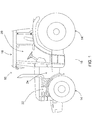
- the drawing shows an agricultural vehicle 10 in the manner of a farm tractor or tractor which is supported on the ground 18 via front and rear wheels 14, 16.
- the vehicle 10 has a cabin 20 in which an operator workstation 22 is arranged.
- an indicated drive 24 and a gear assembly 26 are provided.
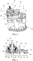
- the transmission assembly 26 has a transmission housing 28, a hydraulic module 30 and a front wheel drive 32, by means of which a front axle or the front wheels 14 of the vehicle 10 can be driven if necessary.
- the front wheel drive 32 and the hydraulic module are mounted in a front area 33 of the transmission housing 28, the front wheel drive 32 having a hydraulically actuable front wheel drive clutch module, which will be referred to below as clutch module 34 for short, with a front wheel drive shaft 36.
- the clutch module 34 can be actuated manually, by an operator, or also automatically in order to selectively connect a front axle (not shown) or the front wheels 14 to the drive 24.
- the hydraulic module 30 has a connection module 38 with a large number of connections 40 for supplying and removing hydraulic and lubricant to the transmission assembly 26, and an end plate 42, the clutch module 34 a clutch housing 44 and a clutch 46, which will be discussed below will be discussed in more detail.
- the clutch 46 is designed in a known manner as a hydraulically actuated multi-plate clutch with an inner and an outer plate carrier 48, 50 and a plurality of clutch plates 52.
- the front-wheel drive 32 has a first gear 54 which can be set in rotation by the drive 24 and a second gear 56 permanently meshing with the first gear 54.
- the inner disk carrier 48 is fixed, the second gear 56 rotatably arranged on the front wheel drive shaft 36, which in turn is rotatably received via a first bearing 58 on the clutch housing 44 and via a second bearing 60 in the hydraulic module 30 or the end plate 42.
- the outer disk carrier 50 is non-rotatably connected to the second gear 56, which is arranged non-rotatably on a gear shaft 64 received in the end plate 42 by a third bearing 62.
- connection module 40 of the hydraulic module 38 is brought up to the transmission housing 28, the transmission shaft 64 being passed through corresponding openings 66 in the connection module 40. Dowel holes 68a provided in the hydraulic module 30 are received.
- the end plate 42 is brought up to the connection module 40 in such a way that the dowel pins 70 correspond to corresponding mating openings 68b in the end plate 42 in order to align them.
- the transmission shaft 64 is passed through an opening 72 in the end plate 42.
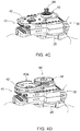
- the end plate 42, together with the connection module 42, is now connected to the transmission housing 28 by means of first fastening means 74 designed as screws.
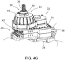
- step five of the assembly the coupling 46 with the front wheel drive shaft 36 is inserted into the bearing shell 60a.
- step six as shown in Figure 4f is shown, the assembly of the coupling housing 44 enclosing the components, which is connected to the end plate 42 and the gear housing 28 by means of second fastening means 76 designed as screws.
- step six the assembly of the first bearing 58 takes place, which is connected to the coupling housing 44 also via third fastening means 78 designed as screws.
- Word list 10 vehicle 66 openings 14 front wheels 68a, b fitting openings 16 rear wheels 70 dowel pins 18 underground 72 opening 20 cabin 74 first fastening means 22 Operator workstation 76 second fastening means 24 drive 78 third fastening means 26 Gear assembly 28 gear housing 30 hydraulic module 32 front-wheel drive 33 Front area 34 coupling module 36 Front wheel drive shaft 38 Connection module 40 connections 42 End plate 44 clutch housing 46 clutch 48, 50 lamellar carriers 52 clutch plates 54 first gear 56 second gear 58 first camp 60 second camp 60a bearing shell 62 third camp 64 gear shaft
Landscapes
- Engineering & Computer Science (AREA)
- Mechanical Engineering (AREA)
- Chemical & Material Sciences (AREA)
- Combustion & Propulsion (AREA)
- Transportation (AREA)
- General Engineering & Computer Science (AREA)
- Arrangement And Driving Of Transmission Devices (AREA)
- Arrangement Of Transmissions (AREA)
Abstract
Description
- Die vorliegende Erfindung betrifft eine Getriebebaugruppe für ein einen zuschaltbaren Vorderradantrieb aufweisendes Fahrzeug, insbesondere ein landwirtschaftliches oder industrielles Arbeitsfahrzeug, mit einem Getriebegehäuse, einem Kupplungsmodul und einem Hydraulikmodul, ein Kupplungsmodul für eine Getriebebaugruppe und ein Fahrzeug, insbesondere ein landwirtschaftliches oder industrielles Arbeitsfahrzeug, mit einer Getriebebaugruppe.
- Nutzfahrzeuge und andere geländegängige Fahrzeuge können mit einem mechanischen Vorderradantrieb ausgestattet sein, um die Vorderräder anzutreiben, beispielsweise um die Traktion zu verbessern. Der Vorderradantrieb bzw. ein Kupplungsmodul des Vorderradantriebs ist üblicherweise an bzw. meist unterhalb eines Getriebegehäuses vorgesehen. Eine Vorderradantriebswelle des Vorderradantriebs ist derart angeordnet, dass sie mit einer Vorderachse des Fahrzeugs verbindbar ist, um vordere Räder des Fahrzeugs anzutreiben. In einem Frontbereich des Getriebegehäuses ist häufig eine Hydraulikversorgung mit diversen Anschlüssen vorgesehen, über die auch der Vorderradantrieb mit Schmier- bzw. Hydraulikmittel versorgt werden kann. Eine derartige Anordnung ist aufwendig und/oder erschwert eine Reparatur bzw. einen Austausch des Vorderradantriebs bzw. des Kupplungsmoduls.
- Die der Erfindung zugrunde liegende Aufgabe wird daher darin gesehen, eine Getriebebaugruppe, ein Kupplungsmodul und Fahrzeug vorzusehen, durch welche die vorgenannten Nachteile überwunden werden.
- Die Aufgabe wird erfindungsgemäß durch die Lehre der Patentansprüche 1, 9 bzw. 10 gelöst. Weitere vorteilhafte Ausgestaltungen und Weiterbildungen der Erfindung gehen aus den Unteransprüchen hervor.
- Diesbezüglich weist eine Getriebebaugruppe für ein einen zuschaltbaren Vorderradantrieb aufweisendes Fahrzeug ein Getriebegehäuse, ein Kupplungsmodul und ein Hydraulikmodul auf, wobei das Hydraulikmodul zwischen dem Kupplungsmodul und dem Getriebegehäuse aufgenommen ist. Durch eine derartige Anordnung, die sich vereinfacht auch als Sandwich-Bauweise beschreiben lässt, ergibt sich eine kompakte Bauform. Darüber hinaus können der Vorderradantrieb bzw. das Kupplungsmodul des Vorderradantriebs und das Hydraulikmodul in besonders einfacher Art und Weise an das Getriebegehäuse ganz oder teilweise an- bzw. von diesem abgebaut werden. Der Zugang zu Bauteilen kann erleichtert und so eine einfachere Zugänglichkeit beispielsweise zum Austausch oder zur Reparatur erzielt werden. Die Getriebebaugruppe kann einfacher und gegebenenfalls leichter ausgebildet werden, da die Anzahl an Hydraulikanschlüssen und/oder Dichtungen bzw. -mitteln, die Länge von bzw. die Anzahl von Hydraulikleitungen reduziert und/oder eine direkte Verbindung von Hydraulikkomponenten bzw. -modulen erzielt werden kann. Bei dem Fahrzeug handelt es sich insbesondere um ein landwirtschaftliches oder industrielles Arbeitsfahrzeug, vorzugsweise in der Art eines Ackerschleppers oder eines Traktors. Es kann sich bei dem Fahrzeug aber auch um eine landwirtschaftliche Erntemaschine, eine selbstfahrende Spritze, ein Baufahrzeug, ein Transport-/Zugfahrzeug oder jedes andere geeignete Fahrzeug, insbesondere Nutzfahrzeug, handeln.
- Sind das Kupplungsmodul und das Hydraulikmodul an einem Frontbereich bzw. einem den vorderen Rädern des Fahrzeugs zugewandten Bereich des Getriebegehäuses vorgesehen, so kann dies eine kompakte Ausbildung begünstigen, insbesondere dadurch, dass das Kupplungsmodul möglichst nahe an einer Vorderachse bzw. den durch den Vorderradantrieb anzutreibenden vorderen Rädern angeordnet werden kann.
- Ein besonders einfacher Aufbau kann erzielt werden, wenn das Hydraulikmodul ein Anschlussmodul und eine Abschlussplatte aufweist. Das Anschlussmodul kann hierbei einen oder auch eine Mehr- bzw. Vielzahl von Hydraulikanschlüssen, beispielsweise zur Zu- und/oder Abfuhr von Schmier- und/oder Hydraulikmittel aufweisen. Die Abschlussplatte kann das Hydraulikmodul zur Umgebung abschließen und/oder zusammen mit diesem an dem Getriebegehäuse befestigt sein. Im Sinne der bereits angesprochenen Sandwich-Bauweise kann das Anschlussmodul an das Getriebegehäuse und die Abschlussplatte an das Kupplungsmodul angrenzen.
- Eine noch kompaktere Bauweise kann erreicht werden, wenn die Abschlussplatte wenigstens ein Lager zur Abstützung wenigstens einer Welle aufweist. Bei dieser Welle kann es sich vorzugsweise um eine Vorderradantriebswelle, die vorgesehen ist, um mit einer Vorderachse bzw. den vorderen Rädern des Fahrzeugs derart verbindbar zu sein, dass diese angetrieben werden können, und/oder eine Getriebewelle handeln, mittels der der Vorderradantrieb wirksam mit einem Antrieb des Fahrzeugs verbunden werden kann.
- Um die Montage bzw. die Ausrichtung des Anschlussmoduls und der Abschlussplatte bei einer Montage zu vereinfachen bzw. zu erleichtern, kann zwischen dem Anschlussmodul und der Abschlussplatte wenigstens ein, vorzugsweise mit entsprechenden Passöffnungen in dem Anschlussmodul bzw. der Anschlussplatte zusammenwirkender Passstift vorgesehen sein. Besonders günstig ist es, wenn zwei vertikal und/oder horizontal beabstandete Passstifte vorgesehen sind.
- Ist wenigstens ein Befestigungsmittel vorgesehen, mittels dem das Kupplungsmodul und das Hydraulikmodul und/oder das Kupplungsmodul und/oder das Hydraulikmodul mit dem Getriebegehäuse verbunden ist, so ergibt sich ein vereinfachter Aufbau, da zur Befestigung der genannten Bauteile eine reduzierte Anzahl von Befestigungsmitteln Anwendung findet.
- Eine besonders einfache Montage bzw. Demontage kann erzielt werden, wenn das wenigstens eine Befestigungsmittel lösbar, vorzugsweise in der Art einer Schraubverbindung vorgesehen ist.
- Besonders günstig ist es, wenn das Kupplungsmodul ein Kupplungsgehäuse zur Aufnahme einer Kupplung zur Zuschaltung eines insbesondere mechanischen Vorderradantriebs und eine Vorderradantriebswelle aufweist, welche sich vorzugsweise von dem Getriebegehäuse zumindest im Wesentlichen horizontal nach vorn bzw. in Richtung der vorderen Räder erstreckt.
- Ein Kupplungsmodul für eine derartige Getriebebaugruppe weist vorzugsweise ein Kupplungsgehäuse, eine Vorderradantriebswelle und eine Kupplung zur selektiven Verbindung der Vorderradantriebswelle mit einem Antrieb des Fahrzeugs auf.
- Es ist vorteilhaft, wenn ein Fahrzeug wenigstens eine zuvor beschriebene Getriebebaugruppe aufweist. Auf diese Weise kann beispielsweise die Komplexität des Fahrzeugs reduziert, Bauraum gespart und/oder anderweitig genutzt und/oder das Fahrzeug kostengünstig hergestellt werden. Bei dem Fahrzeug handelt es sich insbesondere um ein landwirtschaftliches oder industrielles Arbeitsfahrzeug, vorzugsweise in der Art eines Ackerschleppers oder eines Traktors. Es kann sich bei dem Fahrzeug aber auch um eine landwirtschaftliche Erntemaschine, eine selbstfahrende Spritze, ein Baufahrzeug, ein Transport-/Zugfahrzeug oder jedes andere geeignete Fahrzeug, insbesondere Nutzfahrzeug, handeln.
- Anhand der Zeichnung, die mehrere Ausführungsbeispiele der Erfindung zeigt, werden nachfolgend die Erfindung sowie weitere Vorteile und vorteilhafte Weiterbildungen der Erfindung und Ausgestaltungen der Erfindung näher beschrieben und erläutert.
- Es zeigt:
- Fig. 1
- eine Seitenansicht eines landwirtschaftlichen Fahrzeugs mit einem Antrieb und einer Getriebebaugruppe,
- Fig. 2
- die Getriebebaugruppe mit einem Getriebegehäuse, einem Hydraulik- und einem Kupplungsmodul in einer vergrößerten Darstellung,
- Fig. 3
- einen Schnitt entlang der Linie A -A durch das Hydraulik- und das Kupplungsmodul gemäß
Figur 2 und - Fig. 4 a bis g
- einzelne Schritte einer Montage des Hydraulik- bzw. des Kupplungsmoduls an dem Getriebegehäuse.
- Die
Figur 1 der Zeichnung zeigt ein landwirtschaftliches Fahrzeug 10 in der Art eines Ackerschleppers oder Traktors der sich über vordere und rückwärtige Räder 14, 16 auf dem Untergrund 18 abstützt. Das Fahrzeug 10 verfügt über eine Kabine 20, in der ein Bedienerarbeitsplatz 22 angeordnet ist. Darüber hinaus sind ein andeutungsweise gezeigter Antrieb 24 und eine Getriebebaugruppe 26 vorgesehen. - Zur Verdeutlichung wird nun auch auf die
Figur 2 der Zeichnung Bezug genommen. Die Getriebebaugruppe 26 weist ein Getriebegehäuse 28, ein Hydraulikmodul 30 und einen Vorderradantrieb 32 auf, mittels dem bei Bedarf eine Vorderachse bzw. die vorderen Räder 14 des Fahrzeugs 10 angetrieben werden können. Der Vorderradantrieb 32 und das Hydraulikmodul sind in einem Frontbereich 33 des Getriebegehäuse 28 montiert, wobei der Vorderradantrieb 32 ein hydraulisch betätigbares Vorderradantriebs-Kupplungsmodul, das im Folgenden verkürzt als Kupplungsmodul 34 bezeichnet werden wird, mit einer Vorderradantriebswelle 36 aufweist. Das Kupplungsmodul 34 kann manuell, durch eine Bedienerperson, oder auch automatisch betätigt werden kann, um eine nicht gezeigte Vorderachse bzw. die vorderen Räder 14 selektiv mit dem Antrieb 24 zu verbinden. - Das Hydraulikmodul 30 weist ein Anschlussmodul 38 mit einer Vielzahl von Anschlüssen 40 zur Zu- und Abfuhr von Hydraulik- und Schmiermittel zu der Getriebebaugruppe 26, und eine Abschlussplatte 42, das Kupplungsmodul 34 ein Kupplungsgehäuse 44 und eine Kupplung 46 auf, auf die im Folgenden noch genauer eingegangen werden wird.
- Es wird nun auch auf die
Figur 3 der Zeichnung Bezug genommen, in der ein Schnitt durch das Kupplungsgehäuse 44 und die in dem Kupplungsgehäuse 44 angeordnete Kupplung 46, mittels der der Vorderradantrieb 32 zugeschaltet werden kann, gezeigt wird. Die Kupplung 46 ist in bekannter Art und Weise als eine hydraulisch betätigbare Lamellenkupplung mit einem inneren und einem äußeren Lamellenträger 48, 50 und einer Vielzahl von Kupplungslamellen 52 ausgebildet. Darüber hinaus weist der Vorderradantrieb 32 ein durch den Antrieb 24 in Rotation versetzbares erstes Zahnrad 54 und ein zweites, mit dem ersten Zahnrad 54 dauerhaft kämmendes Zahnrad 56 auf. - Der innere Lamellenträger 48 ist fest, das zweite Zahnrad 56 drehbar auf der Vorderradantriebswelle 36 angeordnet, welche wiederum über ein erstes Lager 58 an dem Kupplungsgehäuse 44 und über ein zweites Lager 60 in dem Hydraulikmodul 30 bzw. der Abschlussplatte 42 drehbar aufgenommen wird. Der äußere Lamellenträger 50 ist drehfest mit dem zweiten Zahnrad 56 verbunden, welches drehfest auf einer in der Abschlussplatte 42 durch ein drittes Lager 62 aufgenommen Getriebewelle 64 angeordnet ist.
- Durch eine Aktivierung der Kupplung 46 bzw. ein Beaufschlagen der Kupplung 46 mit Hydraulikdruck wird ein Kraftschluss zwischen den Kupplungslamellen 52 erzielt, der das zweite Zahnrad 56 mit der Vorderradantriebswelle 36 verbindet, so dass diese von dem ersten Zahnrad 54 angetrieben bzw. mit Drehmoment beaufschlagt werden kann.
- Es wird nun auch auf die
Figuren 4 a - g Bezug genommen, in denen eine Montage des Vorderradantriebs 32 bzw. seiner Komponenten vereinfacht dargestellt wird. - Gemäß
Figur 4a wird in einem ersten Schritt das Anschlussmodul 40 des Hydraulikmoduls 38 an das Getriebegehäuse 28 herangebracht, wobei die Getriebewelle 64 durch entsprechende Öffnungen 66 in dem Anschlussmodul 40 hindurchgeführt wird. In dem Hydraulikmodul 30 vorgesehen Passöffnungen 68a sind Passstifte 70 aufgenommen. - In einem in der
Figur 4b der Zeichnung dargestellten zweiten Schritt wird die Abschlussplatte 42 an das Anschlussmodul 40 derart herangebracht, dass die Passstifte 70 mit entsprechenden Passöffnungen 68b in der Abschlussplatte 42 korrespondieren, um diese auszurichten. Die Getriebewelle 64 wird durch eine Öffnung 72 in der Abschlussplatte 42 hindurchgeführt. Die Abschlussplatte 42 wird nun zusammen mit dem Anschlussmodul 42 mittels als Schrauben ausgebildeter erster Befestigungsmittel 74 mit dem Getriebegehäuse 28 verbunden. - In einem nächsten, in der
Figur 4c dargestellten dritten Arbeitsschritt wird das dritte Lager 62 in die Abschlussplatte 42 eingebracht und im Anschluss, wie dies in derFigur 4d gezeigt wird, das erste Zahnrad 54 montiert. Darüber hinaus wird eine Lagerschale 60a des zweiten Lagers 60 montiert. - Im Schritt fünf der Montage (siehe
Figur 4e ) wird die Kupplung 46 mit der Vorderradantriebswelle 36 in die Lagerschale 60a eingesetzt. Im folgenden Schritt sechs erfolgt, wie dies inFigur 4f gezeigt wird, die Montage des die Komponenten umschließenden Kupplungsgehäuses 44, welches mittels als Schrauben ausgebildeter zweiter Befestigungsmittel 76 mit der Abschlussplatte 42 und dem Getriebegehäuse 28 verbunden wird. - Im abschließenden Schritt sechs erfolgt die Montage des ersten Lagers 58, welches mit dem Kupplungsgehäuse 44 ebenfalls über als Schrauben ausgebildete dritte Befestigungsmittel 78 verbunden wird.
- Entsprechend der vorstehenden Beschreibung können die genannten Schritte zur Demontage zumindest im Wesentlichen in umgekehrter Reihenfolge ausgeführt werden.
Wortliste 10 Fahrzeug 66 Öffnungen 14 vordere Räder 68a, b Passöffnungen 16 hintere Räder 70 Passstifte 18 Untergrund 72 Öffnung 20 Kabine 74 erste Befestigungsmittel 22 Bedienerarbeitsplatz 76 zweite Befestigungsmittel 24 Antrieb 78 dritte Befestigungsmittel 26 Getriebebaugruppe 28 Getriebegehäuse 30 Hydraulikmodul 32 Vorderradantrieb 33 Frontbereich 34 Kupplungsmodul 36 Vorderradantriebswelle 38 Anschlussmodul 40 Anschlüsse 42 Abschlussplatte 44 Kupplungsgehäuse 46 Kupplung 48, 50 Lamellenträger 52 Kupplungslamellen 54 erstes Zahnrad 56 zweites Zahnrad 58 erstes Lager 60 zweites Lager 60a Lagerschale 62 drittes Lager 64 Getriebewelle
Claims (10)
- Getriebebaugruppe (26) für ein einen zuschaltbaren Vorderradantrieb (32) aufweisendes Fahrzeug (10), insbesondere ein landwirtschaftliches oder industrielles Arbeitsfahrzeug, mit einem Getriebegehäuse (28), einem Kupplungsmodul (34) und einem Hydraulikmodul (30), dadurch gekennzeichnet, dass das Hydraulikmodul (30) zwischen dem Kupplungsmodul (34) und dem Getriebegehäuse (28) aufgenommen ist.
- Getriebebaugruppe nach Anspruch 1, dadurch gekennzeichnet, dass das Kupplungsmodul (34) und das Hydraulikmodul (30) an einem Frontbereich (33) bzw. einem den vorderen Rädern (14) des Fahrzeugs (10) zugewandten Bereich des Getriebegehäuses (28) vorgesehen sind.
- Getriebebaugruppe nach einem der vorherigen Ansprüche, dadurch gekennzeichnet, dass das Hydraulikmodul (30) ein Anschlussmodul (38) und eine Abschlussplatte (42) aufweist und das Anschlussmodul (38) vorzugsweise an das Getriebegehäuse (28) und die Abschlussplatte (42) an das Kupplungsmodul (34) angrenzt.
- Getriebebaugruppe nach Anspruch 3, dadurch gekennzeichnet, dass zwischen dem Anschlussmodul (38) und der Abschlussplatte (42) wenigstens ein, vorzugsweise mit entsprechenden Passöffnungen (68a, b) in dem Anschlussmodul bzw. der Abschlussplatte (42) zusammenwirkender Passstift (70) vorgesehen ist.
- Getriebebaugruppe nach Anspruch 3 oder 4, dadurch gekennzeichnet, dass die Abschlussplatte (42) wenigstens ein Lager (60, 62) zur Abstützung wenigstens einer Welle, vorzugsweise zumindest einer Vorderradantriebswelle und/oder einer Getriebewelle (64) aufweist.
- Getriebebaugruppe nach einem der vorherigen Ansprüche, dadurch gekennzeichnet, dass wenigstens ein Befestigungsmittel (70, 72, 74) vorgesehen ist, mittels dem das Kupplungsmodul (34) und das Hydraulikmodul (30) und/oder das Kupplungsmodul (34) und/oder das Hydraulikmodul (34) mit dem Getriebegehäuse (28) verbunden ist.
- Getriebebaugruppe nach Anspruch 6, dadurch gekennzeichnet, dass das wenigstens eine Befestigungsmittel (74, 76, 78) lösbar, vorzugsweise in der Art einer Schraubverbindung vorgesehen ist.
- Getriebebaugruppe nach einem der vorherigen Ansprüche, dadurch gekennzeichnet, dass das Kupplungsmodul (34) ein Kupplungsgehäuse (44) zur Aufnahme einer Kupplung (46) zur Zuschaltung eines insbesondere mechanischen Vorderradantriebs (32) und eine Vorderradantriebswelle (36) aufweist, welche sich vorzugsweise von dem Getriebegehäuse (28) zumindest im Wesentlichen horizontal nach vorn bzw. in Richtung der vorderen Räder (14) erstreckt.
- Kupplungsmodul (34) für eine Getriebebaugruppe (26) nach einem der vorherigen Ansprüche mit einem Kupplungsgehäuse (44), einer Vorderradantriebswelle (36) und einer Kupplung (46) zur selektiven Verbindung der Vorderradantriebswelle (36) mit einem Antrieb (24) des Fahrzeugs (10).
- Fahrzeug (10), insbesondere ein landwirtschaftliches oder industrielles Arbeitsfahrzeug, mit einer Getriebebaugruppe (26) nach einem der Ansprüche 1 bis 8.
Applications Claiming Priority (1)
| Application Number | Priority Date | Filing Date | Title |
|---|---|---|---|
| DE102020207779.7A DE102020207779A1 (de) | 2020-06-23 | 2020-06-23 | Getriebebaugruppe, Kupplungsmodul und Fahrzeug |
Publications (2)
| Publication Number | Publication Date |
|---|---|
| EP3929016A1 true EP3929016A1 (de) | 2021-12-29 |
| EP3929016B1 EP3929016B1 (de) | 2024-04-17 |
Family
ID=76444297
Family Applications (1)
| Application Number | Title | Priority Date | Filing Date |
|---|---|---|---|
| EP21179204.9A Active EP3929016B1 (de) | 2020-06-23 | 2021-06-14 | Getriebebaugruppe, kupplungsmodul und fahrzeug |
Country Status (4)
| Country | Link |
|---|---|
| US (1) | US11584223B2 (de) |
| EP (1) | EP3929016B1 (de) |
| BR (1) | BR102021003011A2 (de) |
| DE (1) | DE102020207779A1 (de) |
Citations (3)
| Publication number | Priority date | Publication date | Assignee | Title |
|---|---|---|---|---|
| US6206128B1 (en) * | 1998-10-19 | 2001-03-27 | Kubota Corporation | Working vehicle |
| US20050205386A1 (en) * | 2004-03-22 | 2005-09-22 | Reed William S | Hybrid electro-mechanical transmission with secured hub for park pawl loading and method |
| DE60127348T2 (de) * | 2000-07-10 | 2007-11-29 | Kanzaki Kokyukoki Mfg. Co., Ltd., Amagasaki | Zapfwellenanordnung für Arbeitsfahrzeuge |
Family Cites Families (8)
| Publication number | Priority date | Publication date | Assignee | Title |
|---|---|---|---|---|
| US5855229A (en) | 1996-03-18 | 1999-01-05 | Lectron Products, Inc. | Solenoid manifold assembly |
| JP2002079839A (ja) * | 2000-09-07 | 2002-03-19 | Kanzaki Kokyukoki Mfg Co Ltd | 作業車両のトランスミッション |
| US20040045614A1 (en) | 2002-09-10 | 2004-03-11 | Viswanathan Subramanian | Hydraulic interface plate |
| DE60313112T2 (de) * | 2002-12-24 | 2007-12-20 | Kanzaki Kokyukoki Mfg. Co., Ltd., Amagasaki | Fahrgestellstruktur eines Fahrzeuges |
| US7798174B2 (en) | 2003-08-20 | 2010-09-21 | Eaton Corporation | Electric fluid servo valve and method of making same |
| KR102225785B1 (ko) | 2013-03-14 | 2021-03-11 | 알리손 트랜스미션, 인크. | 하이브리드 차량용 전기 펌프 |
| US10774917B2 (en) * | 2015-05-18 | 2020-09-15 | Yanmar Power Technology Co., Ltd. | Transmission |
| KR20170027992A (ko) * | 2015-09-03 | 2017-03-13 | 대동공업주식회사 | 트랙터 미션 조합 |
-
2020
- 2020-06-23 DE DE102020207779.7A patent/DE102020207779A1/de not_active Withdrawn
-
2021
- 2021-02-18 BR BR102021003011-9A patent/BR102021003011A2/pt unknown
- 2021-03-23 US US17/301,048 patent/US11584223B2/en active Active
- 2021-06-14 EP EP21179204.9A patent/EP3929016B1/de active Active
Patent Citations (3)
| Publication number | Priority date | Publication date | Assignee | Title |
|---|---|---|---|---|
| US6206128B1 (en) * | 1998-10-19 | 2001-03-27 | Kubota Corporation | Working vehicle |
| DE60127348T2 (de) * | 2000-07-10 | 2007-11-29 | Kanzaki Kokyukoki Mfg. Co., Ltd., Amagasaki | Zapfwellenanordnung für Arbeitsfahrzeuge |
| US20050205386A1 (en) * | 2004-03-22 | 2005-09-22 | Reed William S | Hybrid electro-mechanical transmission with secured hub for park pawl loading and method |
Also Published As
| Publication number | Publication date |
|---|---|
| DE102020207779A1 (de) | 2021-12-23 |
| EP3929016B1 (de) | 2024-04-17 |
| US11584223B2 (en) | 2023-02-21 |
| BR102021003011A2 (pt) | 2022-01-04 |
| US20210394613A1 (en) | 2021-12-23 |
Similar Documents
| Publication | Publication Date | Title |
|---|---|---|
| DE3223836C2 (de) | ||
| DE1963019A1 (de) | Antrieb fuer Kraftfahrzeuge | |
| DE10162337B4 (de) | Längs eingebauter Antriebsstrang | |
| DE69404611T2 (de) | Einbauanordnung eines Rücklaufrades | |
| DE69510723T2 (de) | Arbeitsfahrzeug | |
| DE102014009461A1 (de) | Schmieranordnung für eine antriebsachse eines transport- fahrzeuges | |
| EP4155578B1 (de) | Antriebseinrichtung für einen kraftfahrzeugantriebsstrang eines elektrofahrzeugs | |
| EP2122200B1 (de) | Getriebe | |
| EP1634756B1 (de) | Antriebseinrichtung | |
| EP0110270B1 (de) | Fahrzeugrahmen, insbesondere für ein Gleiskettenfahrzeug, und Getriebe hierfür | |
| EP2066925A1 (de) | Mehrstufiges untersetzungsgetriebe | |
| EP3929016B1 (de) | Getriebebaugruppe, kupplungsmodul und fahrzeug | |
| DE2656474C3 (de) | Hydraulische Kriechgang-Antriebsanordnung für ein Nutzfahrzeug | |
| DE102005043633B4 (de) | Differentialmontagestruktur | |
| EP2084430B1 (de) | Getriebe eines von einem motor antreibbaren fahrzeuges | |
| DE10216606B4 (de) | Wischapparat | |
| WO2022243104A1 (de) | Antriebseinrichtung für einen kraftfahrzeugantriebsstrang eines elektrofahrzeugs | |
| DE102022127223A1 (de) | Differentialgetriebe für ein Kraftfahrzeug | |
| DE3704654A1 (de) | Achsenantrieb | |
| EP1995105B1 (de) | Fahrzeugachse | |
| EP0713635A2 (de) | Bodenbearbeitungsmaschine, insbesondere Kreiselegge | |
| DE3501798A1 (de) | Radantrieb fuer einen beim ackerbau benutzbaren traktor | |
| AT413366B (de) | Kraftfahrzeug | |
| DE202008018129U1 (de) | Baugruppe einer Druckmaschine | |
| EP1880124A1 (de) | Mehrgruppengetriebe |
Legal Events
| Date | Code | Title | Description |
|---|---|---|---|
| PUAI | Public reference made under article 153(3) epc to a published international application that has entered the european phase |
Free format text: ORIGINAL CODE: 0009012 |
|
| STAA | Information on the status of an ep patent application or granted ep patent |
Free format text: STATUS: THE APPLICATION HAS BEEN PUBLISHED |
|
| AK | Designated contracting states |
Kind code of ref document: A1 Designated state(s): AL AT BE BG CH CY CZ DE DK EE ES FI FR GB GR HR HU IE IS IT LI LT LU LV MC MK MT NL NO PL PT RO RS SE SI SK SM TR |
|
| B565 | Issuance of search results under rule 164(2) epc |
Effective date: 20210824 |
|
| STAA | Information on the status of an ep patent application or granted ep patent |
Free format text: STATUS: REQUEST FOR EXAMINATION WAS MADE |
|
| 17P | Request for examination filed |
Effective date: 20220629 |
|
| RBV | Designated contracting states (corrected) |
Designated state(s): AL AT BE BG CH CY CZ DE DK EE ES FI FR GB GR HR HU IE IS IT LI LT LU LV MC MK MT NL NO PL PT RO RS SE SI SK SM TR |
|
| STAA | Information on the status of an ep patent application or granted ep patent |
Free format text: STATUS: EXAMINATION IS IN PROGRESS |
|
| 17Q | First examination report despatched |
Effective date: 20230622 |
|
| GRAP | Despatch of communication of intention to grant a patent |
Free format text: ORIGINAL CODE: EPIDOSNIGR1 |
|
| STAA | Information on the status of an ep patent application or granted ep patent |
Free format text: STATUS: GRANT OF PATENT IS INTENDED |
|
| RIC1 | Information provided on ipc code assigned before grant |
Ipc: F16H 57/021 20120101ALN20231123BHEP Ipc: B60K 23/08 20060101ALN20231123BHEP Ipc: F16H 57/02 20120101ALI20231123BHEP Ipc: B60K 17/08 20060101ALI20231123BHEP Ipc: B60K 17/06 20060101ALI20231123BHEP Ipc: B60K 17/02 20060101ALI20231123BHEP Ipc: B60K 17/00 20060101AFI20231123BHEP |
|
| INTG | Intention to grant announced |
Effective date: 20231219 |
|
| GRAS | Grant fee paid |
Free format text: ORIGINAL CODE: EPIDOSNIGR3 |
|
| GRAA | (expected) grant |
Free format text: ORIGINAL CODE: 0009210 |
|
| STAA | Information on the status of an ep patent application or granted ep patent |
Free format text: STATUS: THE PATENT HAS BEEN GRANTED |
|
| AK | Designated contracting states |
Kind code of ref document: B1 Designated state(s): AL AT BE BG CH CY CZ DE DK EE ES FI FR GB GR HR HU IE IS IT LI LT LU LV MC MK MT NL NO PL PT RO RS SE SI SK SM TR |
|
| REG | Reference to a national code |
Ref country code: GB Ref legal event code: FG4D Free format text: NOT ENGLISH |
|
| REG | Reference to a national code |
Ref country code: CH Ref legal event code: EP |
|
| REG | Reference to a national code |
Ref country code: DE Ref legal event code: R096 Ref document number: 502021003346 Country of ref document: DE |
|
| REG | Reference to a national code |
Ref country code: IE Ref legal event code: FG4D Free format text: LANGUAGE OF EP DOCUMENT: GERMAN |
|
| REG | Reference to a national code |
Ref country code: LT Ref legal event code: MG9D |
|
| REG | Reference to a national code |
Ref country code: NL Ref legal event code: MP Effective date: 20240417 |
|
| PG25 | Lapsed in a contracting state [announced via postgrant information from national office to epo] |
Ref country code: NL Free format text: LAPSE BECAUSE OF FAILURE TO SUBMIT A TRANSLATION OF THE DESCRIPTION OR TO PAY THE FEE WITHIN THE PRESCRIBED TIME-LIMIT Effective date: 20240417 |
|
| PG25 | Lapsed in a contracting state [announced via postgrant information from national office to epo] |
Ref country code: NL Free format text: LAPSE BECAUSE OF FAILURE TO SUBMIT A TRANSLATION OF THE DESCRIPTION OR TO PAY THE FEE WITHIN THE PRESCRIBED TIME-LIMIT Effective date: 20240417 |
|
| PG25 | Lapsed in a contracting state [announced via postgrant information from national office to epo] |
Ref country code: IS Free format text: LAPSE BECAUSE OF FAILURE TO SUBMIT A TRANSLATION OF THE DESCRIPTION OR TO PAY THE FEE WITHIN THE PRESCRIBED TIME-LIMIT Effective date: 20240817 |
|
| PG25 | Lapsed in a contracting state [announced via postgrant information from national office to epo] |
Ref country code: BG Free format text: LAPSE BECAUSE OF FAILURE TO SUBMIT A TRANSLATION OF THE DESCRIPTION OR TO PAY THE FEE WITHIN THE PRESCRIBED TIME-LIMIT Effective date: 20240417 |
|
| PG25 | Lapsed in a contracting state [announced via postgrant information from national office to epo] |
Ref country code: HR Free format text: LAPSE BECAUSE OF FAILURE TO SUBMIT A TRANSLATION OF THE DESCRIPTION OR TO PAY THE FEE WITHIN THE PRESCRIBED TIME-LIMIT Effective date: 20240417 Ref country code: FI Free format text: LAPSE BECAUSE OF FAILURE TO SUBMIT A TRANSLATION OF THE DESCRIPTION OR TO PAY THE FEE WITHIN THE PRESCRIBED TIME-LIMIT Effective date: 20240417 |
|
| PG25 | Lapsed in a contracting state [announced via postgrant information from national office to epo] |
Ref country code: GR Free format text: LAPSE BECAUSE OF FAILURE TO SUBMIT A TRANSLATION OF THE DESCRIPTION OR TO PAY THE FEE WITHIN THE PRESCRIBED TIME-LIMIT Effective date: 20240718 |
|
| PG25 | Lapsed in a contracting state [announced via postgrant information from national office to epo] |
Ref country code: PT Free format text: LAPSE BECAUSE OF FAILURE TO SUBMIT A TRANSLATION OF THE DESCRIPTION OR TO PAY THE FEE WITHIN THE PRESCRIBED TIME-LIMIT Effective date: 20240819 |
|
| PG25 | Lapsed in a contracting state [announced via postgrant information from national office to epo] |
Ref country code: ES Free format text: LAPSE BECAUSE OF FAILURE TO SUBMIT A TRANSLATION OF THE DESCRIPTION OR TO PAY THE FEE WITHIN THE PRESCRIBED TIME-LIMIT Effective date: 20240417 |
|
| PG25 | Lapsed in a contracting state [announced via postgrant information from national office to epo] |
Ref country code: PL Free format text: LAPSE BECAUSE OF FAILURE TO SUBMIT A TRANSLATION OF THE DESCRIPTION OR TO PAY THE FEE WITHIN THE PRESCRIBED TIME-LIMIT Effective date: 20240417 |
|
| PG25 | Lapsed in a contracting state [announced via postgrant information from national office to epo] |
Ref country code: LV Free format text: LAPSE BECAUSE OF FAILURE TO SUBMIT A TRANSLATION OF THE DESCRIPTION OR TO PAY THE FEE WITHIN THE PRESCRIBED TIME-LIMIT Effective date: 20240417 |
|
| PG25 | Lapsed in a contracting state [announced via postgrant information from national office to epo] |
Ref country code: PT Free format text: LAPSE BECAUSE OF FAILURE TO SUBMIT A TRANSLATION OF THE DESCRIPTION OR TO PAY THE FEE WITHIN THE PRESCRIBED TIME-LIMIT Effective date: 20240819 Ref country code: PL Free format text: LAPSE BECAUSE OF FAILURE TO SUBMIT A TRANSLATION OF THE DESCRIPTION OR TO PAY THE FEE WITHIN THE PRESCRIBED TIME-LIMIT Effective date: 20240417 Ref country code: NO Free format text: LAPSE BECAUSE OF FAILURE TO SUBMIT A TRANSLATION OF THE DESCRIPTION OR TO PAY THE FEE WITHIN THE PRESCRIBED TIME-LIMIT Effective date: 20240717 Ref country code: LV Free format text: LAPSE BECAUSE OF FAILURE TO SUBMIT A TRANSLATION OF THE DESCRIPTION OR TO PAY THE FEE WITHIN THE PRESCRIBED TIME-LIMIT Effective date: 20240417 Ref country code: IS Free format text: LAPSE BECAUSE OF FAILURE TO SUBMIT A TRANSLATION OF THE DESCRIPTION OR TO PAY THE FEE WITHIN THE PRESCRIBED TIME-LIMIT Effective date: 20240817 Ref country code: HR Free format text: LAPSE BECAUSE OF FAILURE TO SUBMIT A TRANSLATION OF THE DESCRIPTION OR TO PAY THE FEE WITHIN THE PRESCRIBED TIME-LIMIT Effective date: 20240417 Ref country code: GR Free format text: LAPSE BECAUSE OF FAILURE TO SUBMIT A TRANSLATION OF THE DESCRIPTION OR TO PAY THE FEE WITHIN THE PRESCRIBED TIME-LIMIT Effective date: 20240718 Ref country code: FI Free format text: LAPSE BECAUSE OF FAILURE TO SUBMIT A TRANSLATION OF THE DESCRIPTION OR TO PAY THE FEE WITHIN THE PRESCRIBED TIME-LIMIT Effective date: 20240417 Ref country code: ES Free format text: LAPSE BECAUSE OF FAILURE TO SUBMIT A TRANSLATION OF THE DESCRIPTION OR TO PAY THE FEE WITHIN THE PRESCRIBED TIME-LIMIT Effective date: 20240417 Ref country code: BG Free format text: LAPSE BECAUSE OF FAILURE TO SUBMIT A TRANSLATION OF THE DESCRIPTION OR TO PAY THE FEE WITHIN THE PRESCRIBED TIME-LIMIT Effective date: 20240417 Ref country code: RS Free format text: LAPSE BECAUSE OF FAILURE TO SUBMIT A TRANSLATION OF THE DESCRIPTION OR TO PAY THE FEE WITHIN THE PRESCRIBED TIME-LIMIT Effective date: 20240717 |
|
| PG25 | Lapsed in a contracting state [announced via postgrant information from national office to epo] |
Ref country code: DK Free format text: LAPSE BECAUSE OF FAILURE TO SUBMIT A TRANSLATION OF THE DESCRIPTION OR TO PAY THE FEE WITHIN THE PRESCRIBED TIME-LIMIT Effective date: 20240417 |
|
| REG | Reference to a national code |
Ref country code: DE Ref legal event code: R097 Ref document number: 502021003346 Country of ref document: DE |
|
| PG25 | Lapsed in a contracting state [announced via postgrant information from national office to epo] |
Ref country code: EE Free format text: LAPSE BECAUSE OF FAILURE TO SUBMIT A TRANSLATION OF THE DESCRIPTION OR TO PAY THE FEE WITHIN THE PRESCRIBED TIME-LIMIT Effective date: 20240417 |
|
| PG25 | Lapsed in a contracting state [announced via postgrant information from national office to epo] |
Ref country code: CZ Free format text: LAPSE BECAUSE OF FAILURE TO SUBMIT A TRANSLATION OF THE DESCRIPTION OR TO PAY THE FEE WITHIN THE PRESCRIBED TIME-LIMIT Effective date: 20240417 |
|
| PG25 | Lapsed in a contracting state [announced via postgrant information from national office to epo] |
Ref country code: SK Free format text: LAPSE BECAUSE OF FAILURE TO SUBMIT A TRANSLATION OF THE DESCRIPTION OR TO PAY THE FEE WITHIN THE PRESCRIBED TIME-LIMIT Effective date: 20240417 Ref country code: RO Free format text: LAPSE BECAUSE OF FAILURE TO SUBMIT A TRANSLATION OF THE DESCRIPTION OR TO PAY THE FEE WITHIN THE PRESCRIBED TIME-LIMIT Effective date: 20240417 |
|
| PG25 | Lapsed in a contracting state [announced via postgrant information from national office to epo] |
Ref country code: SM Free format text: LAPSE BECAUSE OF FAILURE TO SUBMIT A TRANSLATION OF THE DESCRIPTION OR TO PAY THE FEE WITHIN THE PRESCRIBED TIME-LIMIT Effective date: 20240417 |
|
| PG25 | Lapsed in a contracting state [announced via postgrant information from national office to epo] |
Ref country code: SM Free format text: LAPSE BECAUSE OF FAILURE TO SUBMIT A TRANSLATION OF THE DESCRIPTION OR TO PAY THE FEE WITHIN THE PRESCRIBED TIME-LIMIT Effective date: 20240417 Ref country code: SK Free format text: LAPSE BECAUSE OF FAILURE TO SUBMIT A TRANSLATION OF THE DESCRIPTION OR TO PAY THE FEE WITHIN THE PRESCRIBED TIME-LIMIT Effective date: 20240417 Ref country code: RO Free format text: LAPSE BECAUSE OF FAILURE TO SUBMIT A TRANSLATION OF THE DESCRIPTION OR TO PAY THE FEE WITHIN THE PRESCRIBED TIME-LIMIT Effective date: 20240417 Ref country code: EE Free format text: LAPSE BECAUSE OF FAILURE TO SUBMIT A TRANSLATION OF THE DESCRIPTION OR TO PAY THE FEE WITHIN THE PRESCRIBED TIME-LIMIT Effective date: 20240417 Ref country code: DK Free format text: LAPSE BECAUSE OF FAILURE TO SUBMIT A TRANSLATION OF THE DESCRIPTION OR TO PAY THE FEE WITHIN THE PRESCRIBED TIME-LIMIT Effective date: 20240417 Ref country code: CZ Free format text: LAPSE BECAUSE OF FAILURE TO SUBMIT A TRANSLATION OF THE DESCRIPTION OR TO PAY THE FEE WITHIN THE PRESCRIBED TIME-LIMIT Effective date: 20240417 Ref country code: MC Free format text: LAPSE BECAUSE OF FAILURE TO SUBMIT A TRANSLATION OF THE DESCRIPTION OR TO PAY THE FEE WITHIN THE PRESCRIBED TIME-LIMIT Effective date: 20240417 |
|
| REG | Reference to a national code |
Ref country code: CH Ref legal event code: PL |
|
| PG25 | Lapsed in a contracting state [announced via postgrant information from national office to epo] |
Ref country code: IT Free format text: LAPSE BECAUSE OF FAILURE TO SUBMIT A TRANSLATION OF THE DESCRIPTION OR TO PAY THE FEE WITHIN THE PRESCRIBED TIME-LIMIT Effective date: 20240417 |
|
| PG25 | Lapsed in a contracting state [announced via postgrant information from national office to epo] |
Ref country code: LU Free format text: LAPSE BECAUSE OF NON-PAYMENT OF DUE FEES Effective date: 20240614 |
|
| PLBE | No opposition filed within time limit |
Free format text: ORIGINAL CODE: 0009261 |
|
| STAA | Information on the status of an ep patent application or granted ep patent |
Free format text: STATUS: NO OPPOSITION FILED WITHIN TIME LIMIT |
|
| 26N | No opposition filed |
Effective date: 20250120 |
|
| PG25 | Lapsed in a contracting state [announced via postgrant information from national office to epo] |
Ref country code: IE Free format text: LAPSE BECAUSE OF NON-PAYMENT OF DUE FEES Effective date: 20240614 |
|
| PG25 | Lapsed in a contracting state [announced via postgrant information from national office to epo] |
Ref country code: BE Free format text: LAPSE BECAUSE OF NON-PAYMENT OF DUE FEES Effective date: 20240630 Ref country code: SI Free format text: LAPSE BECAUSE OF FAILURE TO SUBMIT A TRANSLATION OF THE DESCRIPTION OR TO PAY THE FEE WITHIN THE PRESCRIBED TIME-LIMIT Effective date: 20240417 Ref country code: CH Free format text: LAPSE BECAUSE OF NON-PAYMENT OF DUE FEES Effective date: 20240630 |
|
| REG | Reference to a national code |
Ref country code: BE Ref legal event code: MM Effective date: 20240630 |
|
| PGFP | Annual fee paid to national office [announced via postgrant information from national office to epo] |
Ref country code: DE Payment date: 20250521 Year of fee payment: 5 |
|
| PGFP | Annual fee paid to national office [announced via postgrant information from national office to epo] |
Ref country code: GB Payment date: 20250627 Year of fee payment: 5 |
|
| PGFP | Annual fee paid to national office [announced via postgrant information from national office to epo] |
Ref country code: FR Payment date: 20250625 Year of fee payment: 5 |
|
| PGFP | Annual fee paid to national office [announced via postgrant information from national office to epo] |
Ref country code: AT Payment date: 20250721 Year of fee payment: 5 |
|
| PG25 | Lapsed in a contracting state [announced via postgrant information from national office to epo] |
Ref country code: SE Free format text: LAPSE BECAUSE OF FAILURE TO SUBMIT A TRANSLATION OF THE DESCRIPTION OR TO PAY THE FEE WITHIN THE PRESCRIBED TIME-LIMIT Effective date: 20240417 |
|
| PG25 | Lapsed in a contracting state [announced via postgrant information from national office to epo] |
Ref country code: CY Free format text: LAPSE BECAUSE OF FAILURE TO SUBMIT A TRANSLATION OF THE DESCRIPTION OR TO PAY THE FEE WITHIN THE PRESCRIBED TIME-LIMIT; INVALID AB INITIO Effective date: 20210614 |
|
| PG25 | Lapsed in a contracting state [announced via postgrant information from national office to epo] |
Ref country code: HU Free format text: LAPSE BECAUSE OF FAILURE TO SUBMIT A TRANSLATION OF THE DESCRIPTION OR TO PAY THE FEE WITHIN THE PRESCRIBED TIME-LIMIT; INVALID AB INITIO Effective date: 20210614 |