EP3928985B1 - Werkstückausrichtung und -bedrucken - Google Patents
Werkstückausrichtung und -bedrucken Download PDFInfo
- Publication number
- EP3928985B1 EP3928985B1 EP21173772.1A EP21173772A EP3928985B1 EP 3928985 B1 EP3928985 B1 EP 3928985B1 EP 21173772 A EP21173772 A EP 21173772A EP 3928985 B1 EP3928985 B1 EP 3928985B1
- Authority
- EP
- European Patent Office
- Prior art keywords
- workpiece
- workpieces
- support surface
- printing machine
- transport path
- Prior art date
- Legal status (The legal status is an assumption and is not a legal conclusion. Google has not performed a legal analysis and makes no representation as to the accuracy of the status listed.)
- Active
Links
Images


Classifications
-
- B—PERFORMING OPERATIONS; TRANSPORTING
- B41—PRINTING; LINING MACHINES; TYPEWRITERS; STAMPS
- B41M—PRINTING, DUPLICATING, MARKING, OR COPYING PROCESSES; COLOUR PRINTING
- B41M1/00—Inking and printing with a printer's forme
- B41M1/12—Stencil printing; Silk-screen printing
-
- H—ELECTRICITY
- H05—ELECTRIC TECHNIQUES NOT OTHERWISE PROVIDED FOR
- H05K—PRINTED CIRCUITS; CASINGS OR CONSTRUCTIONAL DETAILS OF ELECTRIC APPARATUS; MANUFACTURE OF ASSEMBLAGES OF ELECTRICAL COMPONENTS
- H05K3/00—Apparatus or processes for manufacturing printed circuits
- H05K3/10—Apparatus or processes for manufacturing printed circuits in which conductive material is applied to the insulating support in such a manner as to form the desired conductive pattern
- H05K3/12—Apparatus or processes for manufacturing printed circuits in which conductive material is applied to the insulating support in such a manner as to form the desired conductive pattern using thick film techniques, e.g. printing techniques to apply the conductive material or similar techniques for applying conductive paste or ink patterns
- H05K3/1216—Apparatus or processes for manufacturing printed circuits in which conductive material is applied to the insulating support in such a manner as to form the desired conductive pattern using thick film techniques, e.g. printing techniques to apply the conductive material or similar techniques for applying conductive paste or ink patterns by screen printing or stencil printing
- H05K3/1233—Methods or means for supplying the conductive material and for forcing it through the screen or stencil
-
- B—PERFORMING OPERATIONS; TRANSPORTING
- B41—PRINTING; LINING MACHINES; TYPEWRITERS; STAMPS
- B41F—PRINTING MACHINES OR PRESSES
- B41F15/00—Screen printers
- B41F15/08—Machines
-
- B—PERFORMING OPERATIONS; TRANSPORTING
- B41—PRINTING; LINING MACHINES; TYPEWRITERS; STAMPS
- B41F—PRINTING MACHINES OR PRESSES
- B41F15/00—Screen printers
- B41F15/08—Machines
- B41F15/0881—Machines for printing on polyhedral articles
-
- B—PERFORMING OPERATIONS; TRANSPORTING
- B41—PRINTING; LINING MACHINES; TYPEWRITERS; STAMPS
- B41F—PRINTING MACHINES OR PRESSES
- B41F15/00—Screen printers
- B41F15/14—Details
-
- B—PERFORMING OPERATIONS; TRANSPORTING
- B41—PRINTING; LINING MACHINES; TYPEWRITERS; STAMPS
- B41F—PRINTING MACHINES OR PRESSES
- B41F15/00—Screen printers
- B41F15/14—Details
- B41F15/16—Printing tables
- B41F15/18—Supports for workpieces
-
- B—PERFORMING OPERATIONS; TRANSPORTING
- B41—PRINTING; LINING MACHINES; TYPEWRITERS; STAMPS
- B41F—PRINTING MACHINES OR PRESSES
- B41F15/00—Screen printers
- B41F15/14—Details
- B41F15/16—Printing tables
- B41F15/18—Supports for workpieces
- B41F15/26—Supports for workpieces for articles with flat surfaces
-
- B—PERFORMING OPERATIONS; TRANSPORTING
- B41—PRINTING; LINING MACHINES; TYPEWRITERS; STAMPS
- B41F—PRINTING MACHINES OR PRESSES
- B41F15/00—Screen printers
- B41F15/14—Details
- B41F15/34—Screens, Frames; Holders therefor
-
- B—PERFORMING OPERATIONS; TRANSPORTING
- B41—PRINTING; LINING MACHINES; TYPEWRITERS; STAMPS
- B41F—PRINTING MACHINES OR PRESSES
- B41F15/00—Screen printers
- B41F15/14—Details
- B41F15/34—Screens, Frames; Holders therefor
- B41F15/36—Screens, Frames; Holders therefor flat
-
- B—PERFORMING OPERATIONS; TRANSPORTING
- B41—PRINTING; LINING MACHINES; TYPEWRITERS; STAMPS
- B41F—PRINTING MACHINES OR PRESSES
- B41F15/00—Screen printers
- B41F15/14—Details
- B41F15/44—Squeegees or doctors
-
- B—PERFORMING OPERATIONS; TRANSPORTING
- B41—PRINTING; LINING MACHINES; TYPEWRITERS; STAMPS
- B41F—PRINTING MACHINES OR PRESSES
- B41F21/00—Devices for conveying sheets through printing apparatus or machines
- B41F21/04—Grippers
-
- B—PERFORMING OPERATIONS; TRANSPORTING
- B41—PRINTING; LINING MACHINES; TYPEWRITERS; STAMPS
- B41F—PRINTING MACHINES OR PRESSES
- B41F21/00—Devices for conveying sheets through printing apparatus or machines
- B41F21/08—Combinations of endless conveyors and grippers
-
- B—PERFORMING OPERATIONS; TRANSPORTING
- B41—PRINTING; LINING MACHINES; TYPEWRITERS; STAMPS
- B41F—PRINTING MACHINES OR PRESSES
- B41F33/00—Indicating, counting, warning, control or safety devices
-
- B—PERFORMING OPERATIONS; TRANSPORTING
- B41—PRINTING; LINING MACHINES; TYPEWRITERS; STAMPS
- B41F—PRINTING MACHINES OR PRESSES
- B41F33/00—Indicating, counting, warning, control or safety devices
- B41F33/0009—Central control units
-
- B—PERFORMING OPERATIONS; TRANSPORTING
- B41—PRINTING; LINING MACHINES; TYPEWRITERS; STAMPS
- B41F—PRINTING MACHINES OR PRESSES
- B41F33/00—Indicating, counting, warning, control or safety devices
- B41F33/04—Tripping devices or stop-motions
- B41F33/12—Tripping devices or stop-motions for starting or stopping the machine as a whole
-
- B—PERFORMING OPERATIONS; TRANSPORTING
- B41—PRINTING; LINING MACHINES; TYPEWRITERS; STAMPS
- B41F—PRINTING MACHINES OR PRESSES
- B41F33/00—Indicating, counting, warning, control or safety devices
- B41F33/16—Programming systems for automatic control of sequence of operations
-
- H—ELECTRICITY
- H05—ELECTRIC TECHNIQUES NOT OTHERWISE PROVIDED FOR
- H05K—PRINTED CIRCUITS; CASINGS OR CONSTRUCTIONAL DETAILS OF ELECTRIC APPARATUS; MANUFACTURE OF ASSEMBLAGES OF ELECTRICAL COMPONENTS
- H05K3/00—Apparatus or processes for manufacturing printed circuits
- H05K3/0097—Processing two or more printed circuits simultaneously, e.g. made from a common substrate, or temporarily stacked circuit boards
-
- H—ELECTRICITY
- H05—ELECTRIC TECHNIQUES NOT OTHERWISE PROVIDED FOR
- H05K—PRINTED CIRCUITS; CASINGS OR CONSTRUCTIONAL DETAILS OF ELECTRIC APPARATUS; MANUFACTURE OF ASSEMBLAGES OF ELECTRICAL COMPONENTS
- H05K3/00—Apparatus or processes for manufacturing printed circuits
- H05K3/10—Apparatus or processes for manufacturing printed circuits in which conductive material is applied to the insulating support in such a manner as to form the desired conductive pattern
- H05K3/12—Apparatus or processes for manufacturing printed circuits in which conductive material is applied to the insulating support in such a manner as to form the desired conductive pattern using thick film techniques, e.g. printing techniques to apply the conductive material or similar techniques for applying conductive paste or ink patterns
- H05K3/1216—Apparatus or processes for manufacturing printed circuits in which conductive material is applied to the insulating support in such a manner as to form the desired conductive pattern using thick film techniques, e.g. printing techniques to apply the conductive material or similar techniques for applying conductive paste or ink patterns by screen printing or stencil printing
-
- H—ELECTRICITY
- H10—SEMICONDUCTOR DEVICES; ELECTRIC SOLID-STATE DEVICES NOT OTHERWISE PROVIDED FOR
- H10P—GENERIC PROCESSES OR APPARATUS FOR THE MANUFACTURE OR TREATMENT OF DEVICES COVERED BY CLASS H10
- H10P72/00—Handling or holding of wafers, substrates or devices during manufacture or treatment thereof
- H10P72/30—Handling or holding of wafers, substrates or devices during manufacture or treatment thereof for conveying, e.g. between different workstations
-
- H—ELECTRICITY
- H10—SEMICONDUCTOR DEVICES; ELECTRIC SOLID-STATE DEVICES NOT OTHERWISE PROVIDED FOR
- H10P—GENERIC PROCESSES OR APPARATUS FOR THE MANUFACTURE OR TREATMENT OF DEVICES COVERED BY CLASS H10
- H10P72/00—Handling or holding of wafers, substrates or devices during manufacture or treatment thereof
- H10P72/50—Handling or holding of wafers, substrates or devices during manufacture or treatment thereof for positioning, orientation or alignment
-
- B—PERFORMING OPERATIONS; TRANSPORTING
- B41—PRINTING; LINING MACHINES; TYPEWRITERS; STAMPS
- B41P—INDEXING SCHEME RELATING TO PRINTING, LINING MACHINES, TYPEWRITERS, AND TO STAMPS
- B41P2215/00—Screen printing machines
- B41P2215/10—Screen printing machines characterised by their constructional features
- B41P2215/11—Registering devices
- B41P2215/114—Registering devices with means for displacing the article
Definitions
- This invention relates to a method of printing workpieces, a computer program for controlling a printing machine, a printing machine and a method of aligning a workpiece.
- Industrial screen-printing machines typically apply a conductive print medium, such as solder paste, silver paste or conductive ink, onto a planar workpiece, such as a circuit board, by applying the conductive print medium through a pattern of apertures in a printing screen (sometimes referred to as a mask, foil or stencil) using an angled blade or squeegee.
- a conductive print medium such as solder paste, silver paste or conductive ink
- a planar workpiece such as a circuit board
- a conductive print medium such as solder paste, silver paste or conductive ink
- the workpiece support being capable of withstanding the pressure placed upon it during the printing operation, especially by the downward pressure applied by the squeegee, while maintaining the correct alignment of the workpiece.
- the area of the pattern is relatively small with respect to the area of the screen, it is possible to include more than one pattern within the screen, thus allowing more than one area of a board, or more than one board, to be printed simultaneously using the same screen.
- more than one relatively small screen may be used within the same printing machine to enable the more than one area of a board, or more than one board, to be printed simultaneously using respective screens.
- FIG. 1 schematically shows an example of such an assembly 1, here including a 2 x 4 array of individual support “towers" 2.
- Each tower 2 is topped with a support surface 3 upon which a workpiece (not shown) may be supported during a printing operation.
- each tower 2 is individually actuable to move in orthogonal directions X and Y, which would typically be in the horizontal plane, and also to rotate about an orthogonal Z axis, which would typically extend in the vertical direction to provide so-called theta correction.
- such movement may be advantageously provided through the use of a parallel kinematic actuation system within each tower. Other arrays of greater or smaller dimension are of course possible.
- FIGs. 2A-D schematically show, from above, the following basic steps which may be performed.
- a workpiece support assembly having a 1x4 tower array is shown.
- the individual towers of an array such as that shown in FIG. 1 must have a certain minimum spacing therebetween (i.e. the "pitch" of the array), so that each tower may move and / or rotate freely, without risk of collision with an adjacent tower in the array.
- the present invention seeks to overcome these restrictions in a cost-effective and robust manner.
- this aim is achieved by providing a more flexible stopping arrangement, and thereby selectively controlling the position of carriers within the printing machine.
- a workpiece support system comprising an array of at least two discrete support surfaces, each support surface for supporting a workpiece thereon in use, will be termed a “multiple support system".
- a multiple support system is a “multiple tower support system”, in which each support surface is located on a respective tower, such as described in GB1900058.7 for example.
- Other types of multiple tower support system exist, for example those in which parallel kinematics actuation is not used, or indeed multiple tower support systems in which the individual towers are not capable of the movement within any or all of the X, Y and theta ( ⁇ ) directions, and an example of such a system is described in WO2014166956A1 for example.
- each support surface need not be flat, but could for example be contoured so as to support non-planar workpieces, or have a plurality of pins extending therefrom to support the underside of workpieces which have features located on the underside thereof which cannot contact a support surface directly, such as placed electronics components, holes or vias.
- a method for printing workpieces having a first pitch along a horizontal transport path using a printing machine comprising:
- a printing machine for printing workpieces having a first pitch along a horizontal transport path comprising:
- a method for aligning a workpiece for printing within a printing machine comprising:
- FIGs. 3A-D An embodiment of the present invention is schematically shown with reference to FIGs. 3A-D .
- FIGs. 3A-D show the interior of a printing machine from above ( FIGs. 3A and 3C ), and in a sectional side view along the section A-A ( FIGs. 3B and 3D ), and are aligned so that stationary components, such as towers 12, are shown at the same X-position and scale throughout the four figures.
- FIG. 3A schematically shows, from above, a printing area within a printing machine.
- Rails 10 are provided within the machine which define a horizontal transport path therebetween.
- the rails 10 may conveniently be provided with respective conveyors (not shown) to convey articles, in this case a carrier 14, along the transport path in the direction shown by the large arrow, which is generally denoted the X-direction in the art. Therefore, it is to be understood that the horizontal plane is equivalent to the X-Y plane as shown, while “Z" denotes the vertical direction.
- rails 10 are usually relatively moveable in the Y direction, so that articles of differing widths may be carried therebetween.
- the carrier 14 is shown transparently, so that the positioning of components underneath the carrier 14 can be seen.
- the carrier 14 shown in this embodiment includes eight workpiece receptacles 11, in a four by two matrix.
- each line of two adjacent workpiece receptacles 11 which lie in the same X position will be referred to as "columns”, so that here, four columns are shown, with, for convenience, the leftmost column referred to as the "first column”, and the rightmost column as the "fourth column” for example.
- Each workpiece receptacle 11 is designed to carry a single singulated workpiece (not shown for clarity).
- a workpiece receptacle In order to print a pattern 19 onto a workpiece, it is necessary to align a workpiece receptacle, and hence its received workpiece, above the support surface 13 (see FIG. 3B ) of a tower 12 of tooling (a multiple tower support system) arranged below the horizontal transport path.
- the patterns 19 are formed in a stencil or screen (not shown) located above the horizontal transport path.
- FIG. 3A in this embodiment four towers 12 are provided, in a two-by-two matrix.
- each tower 12 is provided with a support surface 13 at an upper end thereof for engaging with a respective workpiece in use, with the support surfaces 13 being discrete and horizontally spaced.
- the support surfaces 13 are shown as being flat, but in fact these may be contoured or profiled so as to support non-flat workpieces thereon in use.
- the towers 12 are provided on a tooling unit 16, which in turn is mounted on a rising table 15.
- the rising table 15 is vertically-movable between a lower, retracted position (shown in FIG. 3B ) and an upper, extended position (not shown), with the vertical distance travelled being shown as "H" in FIG.
- the support surfaces 13 are of smaller horizontal dimension than their respective towers 12, and are small enough to be able to project within a workpiece receptacle located directly above a respective tower 12 during raising of the rising table 15 to the extended position.
- each support surface 13 of each tower 12 are moveable within the horizontal or X-Y plane, upon receipt of suitable control signals received via the tooling unit 16. Yet more preferably, each support surface 13 is translatable both parallel to the horizontal path and orthogonally to the horizontal path within the horizontal or X-Y plane, and rotatable about a respective vertical or Z axis, similarly to the workpiece support assembly 1 shown in FIGs. 1 and 2 .
- the individual workpiece receptacles 11 have a relatively small pitch of length L in the X direction, while the towers 12 have a relatively large pitch in the X direction, and so it is impossible to locate all workpieces above respective support surfaces 13 at once.
- this problem is solved by enabling the carrier 14, and hence any workpieces carried thereby, to be stopped in more than one location along the X direction.
- a first physical stop 17 is provided proximate the rails to stop the carrier 14 at a first location along the horizontal path, in which workpieces carried in the second and fourth workpiece receptacle columns of the matrix directly overlie respective support surfaces 13, as shown in FIGs.
- the workpieces carried in the first and third workpiece receptacle columns of the matrix do not align with any support surfaces 13, but do overlie the rising table 15.
- the rising table 15 may be raised so that the support surfaces 13 engage with the workpieces in the second and fourth columns of the carrier 14.
- the workpieces may be aligned by suitable movement of the support surfaces 13 in the X-Y plane, and then printed with respective print patterns 19.
- the rising table 15 is then lowered back to the retracted position, so that printed workpieces are returned to their respective workpiece receptacles 11 in carrier 14.
- the carrier 14 is then transported to a second position which is a length L in the X direction, i.e. corresponding to the pitch of the workpiece receptacles 11.
- the carrier 14 is stopped at this second position by a second physical stop 18, so that it is stopped at the position shown in FIGs. 3C and 3D .
- both the first and second physical stops 17, 18 are retractable, so that they can be moved in and out of the horizontal path, to selectively stop the carrier 14 at either the first or second position.
- Controllable physical stops are known in the art per se, and so need not be described further here, but typically comprises an arm, rod or other barrier which may be selectively pivoted or translated into and out of the horizontal path by means of an actuator controlled by a processor, computer or other control means.
- the rising table 15 is then lowered back to the retracted position, so that the recently printed workpieces are returned to their respective workpiece receptacles 11 in carrier 14.
- the carrier 14, with its completely printed workpieces, may then be transported out of the printing machine along the horizontal transport path in the X-direction.
- the concept may be extended to allow efficient printing of carriers having workpiece receptacles at yet smaller pitches. For example, if a carrier having a six-by-two array of workpiece receptacles was used, and the pitch between workpiece receptacles was a third of the pitch between support surfaces, then all workpieces of the carrier could be printed in three print operations. In this case, preferably by printing columns three and six first, then moving the carrier forward by one pitch and printing columns two and five, then moving the carrier forward another one pitch and printing columns one and four.
- FIG. 4A shows the interior of a printing machine from above, while FIG. 4B shows this in a sectional side view along the line B-B.
- Rails 20 define a horizontal transport path therebetween for carrierless workpieces W, with four workpieces W being shown. With such a configuration, the workpieces W are directly supported by, and conveyed along, rails 20.
- a tooling unit 26 which carries a plurality of towers 22 in a four-by-one matrix, with each tower 22 having a support surface 23 at an upper end thereof, the support surfaces being dimensioned and profiled as necessary to adequately support a workpiece W thereon.
- the tooling unit 26 is mounted onto rising table 25.
- the tooling i.e. tooling unit 26, towers 22 and support surfaces 23
- rising table 25 operate in an identical manner as in the previously-described embodiment.
- each support surface 23 engages with its respective overlying workpiece W and lifts it away from the rails 20.
- the workpieces are printed in a single print operation, and then may be returned to the rails 20 by lowering of the rising table 25 back to the retracted position.
- workpieces W can be prevented from stopping above support surfaces 23 of damaged or non-functional towers 22, for example, but instead stopped above an adjacent, fully functional, support surface 23.
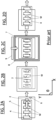
- FIGs. 5A and 5B Another embodiment of the present invention is schematically shown with reference to FIGs. 5A and 5B . This is quite similar to that shown in FIGs. 4A and 4B , however here, rather than the workpieces W being directly supported by rails, they are placed in carriers, with all the workpieces of a plurality of carriers being printable in a single printing operation.
- FIG. 5A shows the interior of a printing machine from above, while FIG. 5B shows this in a sectional side view along the line C-C.
- Rails 30 define a horizontal transport path therebetween for carriers 34, with two carriers 34 being shown.
- two singulated workpieces W may be carried, here shown in a one-by-two array.
- each carrier 34 may be adapted to carry a plurality of workpieces in a non-linear array, such as two-by-two.
- a tooling unit 36 which carries a plurality of towers 32 in a four-by-one matrix, with each tower 32 having a support surface 33 at an upper end thereof, the support surfaces being dimensioned and profiled as necessary to adequately support a workpiece W thereon, other configurations of tooling are possible, if, for example, each carrier 34 carries workpieces W in a non-linear array.
- the tooling unit 36 is mounted onto rising table 35. With such a configuration, the carriers 34 are directly supported by, and conveyed along, rails 30, with carriers 34 able to enter the printing machine one at a time.
- This embodiment may also be combined with the embodiment shown in FIGs. 3A- 3D , so that more than one carrier 34 may be introduced into the printing area above the rising table 35, each carrier 34 carrying workpieces W at a smaller pitch than the pitch between support surfaces 33. In this case, additional stop elements would be required so that each carrier 34 could be stopped at a distance forward along the horizontal transport path equal to one workpiece pitch. Alternate columns of all carriers 34 would be printed in a single print operation, with the remaining columns printed in a second print operation.
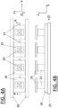
- FIGs. 6A and 6B Another embodiment of the present invention is schematically shown with reference to FIGs. 6A and 6B .
- the arrangement is generally similar to that shown in FIGs. 4A and 4B , with carrierless workpieces W supported and conveyed directly by rails 40.
- the workpieces W are relatively large, so that each may directly overlie first and second adjacent support surfaces 43A, 43B of tooling of a multiple tower support system.
- the printing patterns 49 shown are correspondingly large.
- the tooling i.e. tooling unit 46, towers 42 and support surfaces 43A, 43B located at upper ends of respective towers 42
- rising table 45 operate in an identical manner as in the previously-described embodiments.
- each support surface 43 engages with its respective overlying workpiece W and lifts it away from the rails 40.
- alignment of the workpieces W is then performed, by moving the first and second support surfaces 43A, 43B while engaged with the overlying workpiece W.
- alignment is performed through coordinated movement of the support surfaces 43A, 43B in the horizontal or X-Y plane.
- the workpieces W may then be printed in a single print operation, de-aligned (i.e. returned to the positions at which they arrived above the rising table 45) if necessary and then returned to the rails 40 by lowering of the rising table 45 back to the retracted position.
- workpieces W can be prevented from stopping above support surfaces 43A, 43B of damaged or non-functional towers 42, for example, but instead stopped above alternative fully functional, support surfaces 43A, 43B.
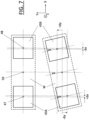
- FIG. 7 schematically shows how the first and second support surfaces 43A, 43B may be used to co-operatively align an overlying workpiece W.
- the top part of FIG. 7 shows, from above, a workpiece W (made transparent for clarity) in a first orientation, supported at each end thereof by respective support surfaces 43A and 43B.
- the geometric centre of workpiece W is shown as 50, while the geometric centres of support surfaces 43A and 43B are shown at 47 and 48 respectively.
- the lower part of FIG. 7 shows, again from above, the positioning of workpiece W and support surfaces 43A, 43B if the workpiece W is caused to rotate by an angle ⁇ about a vertical or Z axis passing through its centre 50, in an anticlockwise direction as shown.
- each support surface 43A, 43B cannot move relative to the overlying workpiece W, since to do so may cause damage to the workpiece W or any features present on its underside.
- the dashed lines show how the relative positions of the workpiece W and support surfaces 43A, 43B change with this rotation. It can be seen that the support surfaces 43A, 43B can be used to effect this rotation if the following conditions are met:
- support surfaces 43A and 43B are possible using a "multiple tower support system", such as that described in GB1900058.7 for example. While FIG. 7 only shows a rotation of workpiece W, it is of course also possible to cause a translation of workpiece W in the X-Y plane, by moving first and second support surfaces 43A and 43B an identical distance (i.e. moving in tandem) in the required direction of translation. Moreover, a combined rotation and translation of workpiece W is possible by superposing such movements.
- FIG. 7 uses adjacent support surfaces 43A and 43B which are spaced in the X direction, i.e. along the horizontal transport path, to enable cooperative alignment, similar alignment is possible if the adjacent support surfaces are instead spaced in the Y direction, i.e. orthogonal to the horizontal transport path. Such an arrangement is useful where the workpieces are relatively long in the Y direction so as to span the two adjacent support surfaces.
- the workpieces to be printed could be carried within a carrier.
- the above-described embodiments are exemplary only, and other possibilities and alternatives within the scope of the invention will be apparent to those skilled in the art.
- the transport control system may for example comprise a sensor associated with each of the first and second locations to sense the presence of a workpiece on the conveyor upstream of the respective location and pass a signal indicative of such presence to the conveyor control. In this way, full and flexible control of the workpieces and their stopping locations is enabled.
- n x m arrays in which "n" refers to the support surfaces spaced along the horizontal transport path or X direction and "m" refers to the support surfaces spaced orthogonal to that horizontal transport path, i.e. along the Y direction.
- n refers to the support surfaces spaced along the horizontal transport path or X direction
- m refers to the support surfaces spaced orthogonal to that horizontal transport path, i.e. along the Y direction.
Landscapes
- Engineering & Computer Science (AREA)
- Mechanical Engineering (AREA)
- Manufacturing & Machinery (AREA)
- Microelectronics & Electronic Packaging (AREA)
- Screen Printers (AREA)
- Printing Methods (AREA)
- Laser Beam Printer (AREA)
Claims (14)
- Verfahren zum Bedrucken von Werkstücken (W) mit einem ersten Abstand entlang eines horizontalen Transportpfades unter Verwendung einer Druckmaschine, die Druckmaschine umfassend:einen höhenverstellbaren Tisch (15, 25, 35, 45), der vertikal zwischen einer unteren, eingefahrenen Position und einer oberen, ausgefahrenen Position beweglich ist, undWerkzeug (16, 26, 36, 46), das an dem höhenverstellbaren Tisch (15, 25, 35, 45) angebracht ist, um damit getragen zu werden; wobei das Werkzeug (16, 26, 36, 46) eine Vielzahl getrennter und horizontal beabstandeter Auflageflächen (13, 23, 33, 43A, 43B) umfasst,wobei die Anordnung derart ist, dass verwendete Werkstücke (W) entlang des horizontalen Transportpfades in die Druckmaschine hinein und durch diese hindurch befördert werden, der sich vertikal über dem Werkzeug (16, 26, 36, 46) befindet, wenn der höhenverstellbare Tisch (15, 25, 35, 45) in der eingefahrenen Position ist, und eine Auflagefläche (13, 23, 33, 43A, 43B) durch Anheben des höhenverstellbaren Tisches (15, 25, 35, 45) in Richtung der ausgefahrenen Position in Eingriff mit einem Werkstück (W) gebracht werden kann, um es zu ermöglichen, dass ein Druckvorgang durchgeführt wird, um das in Eingriff befindliche Werkstück (W) zu bedrucken,wobei das Verfahren das Transportieren einer Vielzahl von zu bedruckenden Werkstücken (W) in die Druckmaschine hinein entlang des horizontalen Transportpfades umfasst,wobei die Vielzahl von Auflageflächen entlang des horizontalen Transportpfades in einem zweiten Abstand beabstandet sind, der größer als der erste Abstand ist, undder Transport so gesteuert wird, dass jedes Werkstück (W) der Vielzahl von Werkstücken (W) an einem entsprechenden ersten und zweiten Ort innerhalb der Druckmaschine angehalten wird, wobei der erste und der zweite Ort entlang des horizontalen Transportpfades beabstandet sind und jeweils direkt über dem höhenverstellbaren Tisch (15, 25, 35, 45), wenn er sich in eingefahrener Position befindet, positioniert sind, wobei mindestens einer aus dem ersten und dem zweiten Ort direkt über einer Auflagefläche (13, 23, 33, 43A, 43B) des Werkzeugs (16, 26, 36, 46) positioniert ist.
- Verfahren nach Anspruch 1, wobei die zu bedruckenden Werkstücke (W) mindestens ein Werkstück (W) in einer ersten Anordnung und mindestens ein Werkstück (W) in einer zweiten Anordnung beinhalten, wobei die Werkstücke (W) der ersten und der zweiten Anordnung entlang des horizontalen Transportpfades verschachtelt sind, wobei das Verfahren die folgenden Schritte umfasst:i) Steuern des Transports, um die Vielzahl von Werkstücken (W) entlang des horizontalen Transportpfades zu bewegen und ein Werkstück (W) der ersten Anordnung an einem ersten entsprechenden Ort anzuhalten, an dem es direkt über einer Auflagefläche (13, 23, 33, 43A, 43B) liegt, und ein Werkstück (W) der zweiten Anordnung an einem ersten entsprechenden Ort anzuhalten, an dem es direkt über dem höhenverstellbaren Tisch (15, 25, 35, 45) aber nicht über einer Auflagefläche (13, 23, 33, 43A, 43B) liegt,ii) Anheben des höhenverstellbaren Tisches (15, 25, 35, 45), um das Werkstück (W) der ersten Anordnung in Eingriff mit seiner darunterliegenden Auflagefläche (13, 23, 33, 43A, 43B) zu bringen,iii) Durchführen eines ersten Druckvorgangs, um das in Eingriff befindliche Werkstück (W) der ersten Anordnung zu bedrucken,iv) Absenken des höhenverstellbaren Tisches (15, 25, 35, 45), um das Werkstück (W) der ersten Anordnung außer Eingriff mit der Auflagefläche (13, 23, 33, 43A, 43B) zu bringen,v) Steuern des Transports, um die Vielzahl von Werkstücken (W) entlang des horizontalen Transportpfades zu bewegen und das Werkstück (W) der zweiten Anordnung an einem zweiten entsprechenden Ort anzuhalten, an dem es direkt über einer Auflagefläche (13, 23, 33, 43A, 43B) liegt, und das Werkstück (W) der ersten Anordnung an einem zweiten entsprechenden Ort anzuhalten, an dem es direkt über dem höhenverstellbaren Tisch (15, 25, 35, 45) aber nicht über einer Auflagefläche (13, 23, 33, 43A, 43B) liegt,vi) Anheben des höhenverstellbaren Tisches (15, 25, 35, 45), um das Werkstück (W) der zweiten Anordnung in Eingriff mit seiner darunterliegenden Auflagefläche (13, 23, 33, 43A, 43B) zu bringen,vii) Durchführen eines zweiten Druckvorgangs, um das in Eingriff befindliche Werkstück (W) in der zweiten Anordnung zu bedrucken,viii) Absenken des höhenverstellbaren Tischs (15, 25, 35, 45), um das Werkstück (W) der zweiten Anordnung außer Eingriff mit der Auflagefläche (13, 23, 33, 43A, 43B) zu bringen.
- Verfahren nach Anspruch 2, wobei ein Werkstück (W) der ersten Anordnung und ein Werkstück (W) der zweiten Anordnung auf einem gemeinsamen Träger (14, 34) in die Druckmaschine hinein befördert werden, und der Träger (14, 34) in Schritt i) entlang des horizontalen Transportpfades zu einem ersten Trägerort befördert wird, und der Träger (14, 34) in Schritt v) entlang des horizontalen Transportpfades zu einem zweiten Trägerort befördert wird.
- Verfahren nach Anspruch 1, wobei eine Vielzahl von Anhalteorten entlang des horizontalen Transportpfades vorgesehen ist, und der Transport so gesteuert wird, dass jedes Werkstück (W) an einem ausgewählten entsprechenden Anhalteort angehalten wird, optional wird ein Werkstück (W) an jedem Anhalteort angehalten, und ein einziger Druckvorgang durchgeführt, um jedes Werkstück (W), das am Anhalteort angehalten wird, zu bedrucken.
- Verfahren nach einem der vorstehenden Ansprüche, wobei das Werkzeug (16, 26, 36, 46) eine Vielzahl von Masten (12, 22, 32, 42) umfasst, wobei jede Auflagefläche (13, 23, 33, 43A, 43B) an einem oberen Ende eines entsprechenden Masten (12, 22, 32, 42) positioniert ist und jede Auflagefläche (13, 23, 33, 43A, 43B) innerhalb der horizontalen Ebene beweglich ist.
- Verfahren nach Anspruch 5, wobei jede Auflagefläche (13, 23, 33, 43A, 43B) sowohl parallel zu dem horizontalen Pfad als auch orthogonal zu dem horizontalen Pfad innerhalb der horizontalen Ebene verschiebbar und um eine entsprechende vertikale Achse drehbar ist.
- Verfahren nach Anspruch 5 oder 6, umfassend das Anhalten eines Werkstücks (W) an einem ersten Ort, in dem es direkt über einer ersten und einer zweiten Auflagefläche liegt, sodass das Anheben des höhenverstellbaren Tisches (15, 25, 35, 45) in Richtung der ausgefahrenen Position sowohl die erste als auch die zweite Auflagefläche (13, 23, 33, 43A, 43B) in Eingriff mit dem Werkstück (W) bringt.
- Verfahren nach Anspruch 7, umfassend den Schritt des Anpassens der Position und / oder der Drehung des Werkstücks (W) durch Bewegen der ersten und der zweiten Auflagefläche (13, 23, 33, 43A, 43B), wenn diese mit dem Werkstück (W) in Eingriff sind.
- Computerprogramm zum Steuern einer Druckmaschine, um das Verfahren nach einem der vorstehenden Ansprüche durchzuführen.
- Druckmaschine zum Bedrucken von Werkstücken (W) mit einem ersten Abstand entlang eines horizontalen Transportpfades, umfassend:einen höhenverstellbaren Tisch (15, 25, 35, 45), der vertikal zwischen einer unteren, eingefahrenen Position und einer oberen, ausgefahrenen Position beweglich ist,Werkzeug, das an dem höhenverstellbaren Tisch (15, 25, 35, 45) angebracht ist, um darin getragen zu werden; wobei das Werkzeug eine Vielzahl getrennter und horizontal beabstandeter Auflageflächen (13, 23, 33, 43A, 43B) umfasst,ein Förderband, das dazu betriebsfähig ist, Werkstücke entlang des horizontalen Pfades in die Druckmaschine hinein und durch diese hindurch zu transportieren, der sich vertikal über dem Werkzeug befindet, wenn der höhenverstellbare Tisch (15, 25, 35, 45) in der eingefahrenen Position ist, undwobei die Vielzahl von Auflageflächen entlang des horizontalen Transportpfades in einem zweiten Abstand beabstandet sind, der größer als der erste Abstand ist, undwobei die Druckmaschine ferner ein Transportsteuersystem umfasst, das dazu betriebsfähig ist, ein Werkstück (W) auf dem Förderband selektiv entweder an einem ersten oder an einem zweiten Ort innerhalb der Druckmaschine anzuhalten, wobei der erste und der zweite Ort entlang des horizontalen Transportpfade beabstandet sind und jeweils direkt über dem höhenverstellbaren Tisch (15, 25, 35, 45), wenn er sich in eingefahrener Position befindet, positioniert sind, wobei mindestens einer aus dem ersten und dem zweiten Ort direkt über einer Auflagefläche (13, 23, 33, 43A, 43B) des Werkzeugs positioniert ist.
- Druckmaschine nach Anspruch 10, wobei das Transportsteuersystem Folgendes umfasst:ein erstes physisches Anhalteelement (17), das dazu betriebsfähig ist, ein Werkstück (W) an dem ersten Ort anzuhalten, undein zweites physisches Anhalteelement (18), das dazu betriebsfähig ist, ein Werkstück (W) an dem zweiten Ort anzuhalten.
- Druckmaschine nach Anspruch 10, wobei das Transportsteuersystem Folgendes umfasst:
eine Förderbandsteuerung, die dazu betriebsfähig ist, den Betrieb des Förderbands zu steuern, um ein Werkstück (W) an einem ausgewählten Ort aus dem ersten und dem zweiten Ort zum Anhalten zu bringen. - Druckmaschine nach Anspruch 12, wobei das Transportsteuersystem Folgendes umfasst:
einen Sensor, der jeweils dem ersten und dem zweiten Ort zugeordnet ist, um das Vorhandensein eines Werkstücks (W) auf dem Förderband vorgelagert zu dem entsprechenden Ort zu erfassen und ein Signal, das dieses Vorhandensein anzeigt, an die Förderbandsteuerung weiterzugeben. - Verfahren zum Ausrichten eines Werkstücks (W) zum Bedrucken innerhalb einer Druckmaschine, die Druckmaschine umfassend:einen höhenverstellbaren Tisch (45), der vertikal zwischen einer unteren, eingefahrenen Position und einer oberen, ausgefahrenen Position beweglich ist, undWerkzeug (46), das an dem höhenverstellbaren Tisch (45) angebracht ist, um darin getragen zu werden; wobei das Werkzeug (46) eine Vielzahl getrennter und horizontal beabstandeter Auflageflächen (43A, 43B) umfasst, wobei das Werkzeug (46) eine Vielzahl von Masten (42) umfasst, wobei jede Auflagefläche der Vielzahl von Auflageflächen (43A, 43B) an einem oberen Ende eines entsprechenden Masten (42) positioniert ist und jede Auflagefläche (43A, 43B) innerhalb der horizontalen Ebene beweglich ist, und wobei jeder Mast (42) einzeln betätigbar ist, um seine Auflagefläche (43A, 43B) sowohl parallel als auch orthogonal zu dem horizontalen Pfad innerhalb der horizontalen Ebene zu verschieben und die Auflagefläche (43A, 43B) um eine entsprechende Achse zu drehen,wobei das Verfahren die folgenden Schritte umfasst:i) Transportieren eines Werkstücks (W) entlang eines horizontalen Transportpfades in die Druckmaschine hinein und durch diese hindurch,ii) Anhalten des Werkstücks (W) an einem Ort, in dem das Werkstück (W) direkt über einer ersten und einer zweiten Auflagefläche der Vielzahl von Auflageflächen (43A, 43B) liegt,iii) Ineingriffbringen des Werkstücks (W) mit sowohl der ersten als auch der zweiten Auflagefläche (43A, 43B), undiv) Ausrichten des Werkstücks (W) durch Bewegen der ersten und der zweiten Auflagefläche (43A, 43B), während diese mit dem Werkstück (W) in Eingriff sind.
Priority Applications (1)
| Application Number | Priority Date | Filing Date | Title |
|---|---|---|---|
| RS20241322A RS66252B1 (sr) | 2020-06-22 | 2021-05-13 | Poravnavanje i štampanje radnog komada |
Applications Claiming Priority (1)
| Application Number | Priority Date | Filing Date | Title |
|---|---|---|---|
| GB2009474.4A GB2596517A (en) | 2020-06-22 | 2020-06-22 | Workpiece alignment and printing |
Publications (3)
| Publication Number | Publication Date |
|---|---|
| EP3928985A1 EP3928985A1 (de) | 2021-12-29 |
| EP3928985C0 EP3928985C0 (de) | 2024-09-18 |
| EP3928985B1 true EP3928985B1 (de) | 2024-09-18 |
Family
ID=71838336
Family Applications (1)
| Application Number | Title | Priority Date | Filing Date |
|---|---|---|---|
| EP21173772.1A Active EP3928985B1 (de) | 2020-06-22 | 2021-05-13 | Werkstückausrichtung und -bedrucken |
Country Status (8)
| Country | Link |
|---|---|
| EP (1) | EP3928985B1 (de) |
| JP (1) | JP7307124B2 (de) |
| KR (1) | KR102523222B1 (de) |
| CN (1) | CN113895142B (de) |
| GB (1) | GB2596517A (de) |
| HU (1) | HUE069292T2 (de) |
| RS (1) | RS66252B1 (de) |
| TW (1) | TWI773302B (de) |
Families Citing this family (4)
| Publication number | Priority date | Publication date | Assignee | Title |
|---|---|---|---|---|
| GB2613575A (en) * | 2021-12-06 | 2023-06-14 | Asm Assembly Systems Singapore Pte Ltd | Offset printing of singulated workpieces |
| GB2619961A (en) * | 2022-06-23 | 2023-12-27 | Asm Assembly Systems Singapore Pte Ltd | Alignment of singulated substrates |
| GB2640904A (en) * | 2024-05-09 | 2025-11-12 | Asmpt Smt Singapore Pte Ltd | Alignment systems and methods |
| GB2641783A (en) | 2024-06-12 | 2025-12-17 | Asmpt Smt Singapore Pte Ltd | Workpiece support assembly |
Family Cites Families (24)
| Publication number | Priority date | Publication date | Assignee | Title |
|---|---|---|---|---|
| JPH1076631A (ja) * | 1996-09-02 | 1998-03-24 | Minoguruupu:Kk | スクリーン印刷機における被印刷物搬送装置及び被印刷物搬送方法 |
| US5873939A (en) * | 1997-02-21 | 1999-02-23 | Doyle; Dennis G. | Dual track stencil/screen printer |
| US6066206A (en) * | 1997-02-21 | 2000-05-23 | Speedline Technologies, Inc. | Dual track stenciling system with solder gathering head |
| KR100250907B1 (ko) * | 1997-12-17 | 2000-04-01 | 김재석 | 차량의 아웃사이드 미러용 거울에 문자 인쇄장치 |
| JP2004160732A (ja) | 2002-11-11 | 2004-06-10 | Asahi Glass Co Ltd | 複数枚のガラス板に同時印刷するスクリーン印刷機 |
| JP4241639B2 (ja) | 2005-02-14 | 2009-03-18 | セイコーエプソン株式会社 | 液滴吐出装置及び液滴吐出ヘッドの保守方法 |
| JP4356769B2 (ja) * | 2007-05-22 | 2009-11-04 | パナソニック株式会社 | スクリーン印刷装置およびスクリーン印刷方法 |
| JP5023904B2 (ja) * | 2007-09-11 | 2012-09-12 | パナソニック株式会社 | スクリーン印刷装置 |
| JP5053913B2 (ja) * | 2008-04-11 | 2012-10-24 | ミナミ株式会社 | スクリーン印刷機における基板の位置及び角度補正装置 |
| JP5514457B2 (ja) * | 2009-03-06 | 2014-06-04 | アスリートFa株式会社 | マスクを用いた処理装置および方法 |
| JP2011031588A (ja) | 2009-08-06 | 2011-02-17 | Panasonic Corp | スクリーン印刷装置およびスクリーン印刷方法 |
| JP2011056761A (ja) * | 2009-09-09 | 2011-03-24 | Micro-Tec Co Ltd | 印刷装置及び印刷物の製造方法 |
| JP5759348B2 (ja) * | 2011-11-30 | 2015-08-05 | 株式会社Screenホールディングス | パターン形成装置およびパターン形成方法 |
| WO2014083605A1 (ja) * | 2012-11-27 | 2014-06-05 | 富士機械製造株式会社 | 基板印刷装置 |
| TWI695782B (zh) * | 2013-04-08 | 2020-06-11 | 新加坡商Asm組合系統新加坡有限公司 | 用於支撐工件的支撐部件、包含複數個所述支撐部件的工件支撐總成、結合所述工件支撐總成的工件參考系統、包含所述工件支撐總成的工件參考系統、用於參考工件的工件參考總成、結合所述工件參考總成的工件參考系統以及參考單一化工件之方法 |
| US9126398B2 (en) * | 2013-07-26 | 2015-09-08 | Asm Assembly Systems Singapore Pte Ltd | Apparatus for paste material printing, and printing method |
| JP6223091B2 (ja) * | 2013-09-25 | 2017-11-01 | 株式会社Screenホールディングス | 位置計測装置、アライメント装置、パターン描画装置および位置計測方法 |
| TW201532855A (zh) | 2013-10-23 | 2015-09-01 | Ats自動模具系統股份有限公司 | 複數零件的裝飾系統與方法 |
| CN105690754A (zh) * | 2014-11-28 | 2016-06-22 | 上海普利生机电科技有限公司 | 光固化型3d打印方法、设备及其图像曝光系统 |
| WO2017022127A1 (ja) * | 2015-08-06 | 2017-02-09 | 富士機械製造株式会社 | 印刷システム及び印刷方法 |
| CN105668237B (zh) * | 2016-04-21 | 2017-12-01 | 深圳市龙方自动化科技有限公司 | 全自动丝网印刷机 |
| CN205705715U (zh) | 2016-06-23 | 2016-11-23 | 埃科产品创意开发(深圳)有限公司 | 全自动移印机设备 |
| JP7108807B2 (ja) | 2017-06-01 | 2022-07-29 | パナソニックIpマネジメント株式会社 | スクリーン印刷システムおよびスクリーン印刷方法 |
| WO2020008761A1 (ja) | 2018-07-04 | 2020-01-09 | パナソニックIpマネジメント株式会社 | スクリーン印刷装置およびスクリーン印刷方法 |
-
2020
- 2020-06-22 GB GB2009474.4A patent/GB2596517A/en not_active Withdrawn
-
2021
- 2021-05-07 TW TW110116522A patent/TWI773302B/zh active
- 2021-05-13 EP EP21173772.1A patent/EP3928985B1/de active Active
- 2021-05-13 RS RS20241322A patent/RS66252B1/sr unknown
- 2021-05-13 HU HUE21173772A patent/HUE069292T2/hu unknown
- 2021-06-11 KR KR1020210075919A patent/KR102523222B1/ko active Active
- 2021-06-17 CN CN202110670045.XA patent/CN113895142B/zh active Active
- 2021-06-21 JP JP2021102335A patent/JP7307124B2/ja active Active
Also Published As
| Publication number | Publication date |
|---|---|
| KR20210157872A (ko) | 2021-12-29 |
| EP3928985C0 (de) | 2024-09-18 |
| JP2022001434A (ja) | 2022-01-06 |
| TW202201148A (zh) | 2022-01-01 |
| JP7307124B2 (ja) | 2023-07-11 |
| CN113895142B (zh) | 2023-05-09 |
| EP3928985A1 (de) | 2021-12-29 |
| CN113895142A (zh) | 2022-01-07 |
| GB202009474D0 (en) | 2020-08-05 |
| TWI773302B (zh) | 2022-08-01 |
| KR102523222B1 (ko) | 2023-04-20 |
| RS66252B1 (sr) | 2024-12-31 |
| HUE069292T2 (hu) | 2025-02-28 |
| GB2596517A (en) | 2022-01-05 |
Similar Documents
| Publication | Publication Date | Title |
|---|---|---|
| EP3928985B1 (de) | Werkstückausrichtung und -bedrucken | |
| JP2018086854A (ja) | ペースト材料を印刷するための装置および印刷方法 | |
| KR102940603B1 (ko) | 개별화된 기판의 정렬 | |
| US20220203670A1 (en) | Apparatus and method for the production of three-dimensional screen-printed workpieces | |
| KR102407911B1 (ko) | 단일화 소재 정렬 | |
| US20220176690A1 (en) | Apparatus and method for the production of three-dimensional screen-printed workpieces | |
| JP2009070867A (ja) | スクリーン印刷装置 | |
| US20220176628A1 (en) | Apparatus and method for the production of three-dimensional screen-printed workpieces | |
| EP4364949B1 (de) | Referenziersystem für vereinzelte werkstücke | |
| KR101117121B1 (ko) | 스크린 프린터 | |
| JP2010129866A (ja) | 導電性ボール搭載装置 | |
| EP4190562A1 (de) | Versetzter druck vereinzelter werkstücke | |
| JP4858520B2 (ja) | スクリーン印刷機及びスクリーン印刷方法 | |
| US12172376B2 (en) | Method for the production of three-dimensional screen-printed workpieces | |
| KR102702358B1 (ko) | 기판용 식별코드 각인 장치 | |
| JPS6333979B2 (de) | ||
| JP2010109218A (ja) | 基板生産装置及び基板生産方法 | |
| JPH06125200A (ja) | プリント基板の検査装置 |
Legal Events
| Date | Code | Title | Description |
|---|---|---|---|
| PUAI | Public reference made under article 153(3) epc to a published international application that has entered the european phase |
Free format text: ORIGINAL CODE: 0009012 |
|
| STAA | Information on the status of an ep patent application or granted ep patent |
Free format text: STATUS: THE APPLICATION HAS BEEN PUBLISHED |
|
| AK | Designated contracting states |
Kind code of ref document: A1 Designated state(s): AL AT BE BG CH CY CZ DE DK EE ES FI FR GB GR HR HU IE IS IT LI LT LU LV MC MK MT NL NO PL PT RO RS SE SI SK SM TR |
|
| B565 | Issuance of search results under rule 164(2) epc |
Effective date: 20211109 |
|
| STAA | Information on the status of an ep patent application or granted ep patent |
Free format text: STATUS: REQUEST FOR EXAMINATION WAS MADE |
|
| 17P | Request for examination filed |
Effective date: 20220613 |
|
| RBV | Designated contracting states (corrected) |
Designated state(s): AL AT BE BG CH CY CZ DE DK EE ES FI FR GB GR HR HU IE IS IT LI LT LU LV MC MK MT NL NO PL PT RO RS SE SI SK SM TR |
|
| RAP3 | Party data changed (applicant data changed or rights of an application transferred) |
Owner name: ASMPT SMT SINGAPORE PTE. LTD |
|
| STAA | Information on the status of an ep patent application or granted ep patent |
Free format text: STATUS: EXAMINATION IS IN PROGRESS |
|
| 17Q | First examination report despatched |
Effective date: 20230509 |
|
| P01 | Opt-out of the competence of the unified patent court (upc) registered |
Effective date: 20230530 |
|
| GRAP | Despatch of communication of intention to grant a patent |
Free format text: ORIGINAL CODE: EPIDOSNIGR1 |
|
| STAA | Information on the status of an ep patent application or granted ep patent |
Free format text: STATUS: GRANT OF PATENT IS INTENDED |
|
| GRAJ | Information related to disapproval of communication of intention to grant by the applicant or resumption of examination proceedings by the epo deleted |
Free format text: ORIGINAL CODE: EPIDOSDIGR1 |
|
| STAA | Information on the status of an ep patent application or granted ep patent |
Free format text: STATUS: EXAMINATION IS IN PROGRESS |
|
| INTG | Intention to grant announced |
Effective date: 20240212 |
|
| INTC | Intention to grant announced (deleted) | ||
| RAP3 | Party data changed (applicant data changed or rights of an application transferred) |
Owner name: ASMPT SMT SINGAPORE PTE. LTD. |
|
| GRAP | Despatch of communication of intention to grant a patent |
Free format text: ORIGINAL CODE: EPIDOSNIGR1 |
|
| STAA | Information on the status of an ep patent application or granted ep patent |
Free format text: STATUS: GRANT OF PATENT IS INTENDED |
|
| INTG | Intention to grant announced |
Effective date: 20240613 |
|
| GRAS | Grant fee paid |
Free format text: ORIGINAL CODE: EPIDOSNIGR3 |
|
| GRAA | (expected) grant |
Free format text: ORIGINAL CODE: 0009210 |
|
| STAA | Information on the status of an ep patent application or granted ep patent |
Free format text: STATUS: THE PATENT HAS BEEN GRANTED |
|
| AK | Designated contracting states |
Kind code of ref document: B1 Designated state(s): AL AT BE BG CH CY CZ DE DK EE ES FI FR GB GR HR HU IE IS IT LI LT LU LV MC MK MT NL NO PL PT RO RS SE SI SK SM TR |
|
| REG | Reference to a national code |
Ref country code: GB Ref legal event code: FG4D |
|
| REG | Reference to a national code |
Ref country code: CH Ref legal event code: EP |
|
| REG | Reference to a national code |
Ref country code: IE Ref legal event code: FG4D |
|
| REG | Reference to a national code |
Ref country code: DE Ref legal event code: R096 Ref document number: 602021018854 Country of ref document: DE |
|
| U01 | Request for unitary effect filed |
Effective date: 20241010 |
|
| P04 | Withdrawal of opt-out of the competence of the unified patent court (upc) registered |
Free format text: CASE NUMBER: APP_58613/2024 Effective date: 20241026 |
|
| U07 | Unitary effect registered |
Designated state(s): AT BE BG DE DK EE FI FR IT LT LU LV MT NL PT RO SE SI Effective date: 20241030 |
|
| PG25 | Lapsed in a contracting state [announced via postgrant information from national office to epo] |
Ref country code: NO Free format text: LAPSE BECAUSE OF FAILURE TO SUBMIT A TRANSLATION OF THE DESCRIPTION OR TO PAY THE FEE WITHIN THE PRESCRIBED TIME-LIMIT Effective date: 20241218 |
|
| PG25 | Lapsed in a contracting state [announced via postgrant information from national office to epo] |
Ref country code: GR Free format text: LAPSE BECAUSE OF FAILURE TO SUBMIT A TRANSLATION OF THE DESCRIPTION OR TO PAY THE FEE WITHIN THE PRESCRIBED TIME-LIMIT Effective date: 20241219 |
|
| PG25 | Lapsed in a contracting state [announced via postgrant information from national office to epo] |
Ref country code: HR Free format text: LAPSE BECAUSE OF FAILURE TO SUBMIT A TRANSLATION OF THE DESCRIPTION OR TO PAY THE FEE WITHIN THE PRESCRIBED TIME-LIMIT Effective date: 20240918 |
|
| PG25 | Lapsed in a contracting state [announced via postgrant information from national office to epo] |
Ref country code: NO Free format text: LAPSE BECAUSE OF FAILURE TO SUBMIT A TRANSLATION OF THE DESCRIPTION OR TO PAY THE FEE WITHIN THE PRESCRIBED TIME-LIMIT Effective date: 20241218 Ref country code: HR Free format text: LAPSE BECAUSE OF FAILURE TO SUBMIT A TRANSLATION OF THE DESCRIPTION OR TO PAY THE FEE WITHIN THE PRESCRIBED TIME-LIMIT Effective date: 20240918 Ref country code: GR Free format text: LAPSE BECAUSE OF FAILURE TO SUBMIT A TRANSLATION OF THE DESCRIPTION OR TO PAY THE FEE WITHIN THE PRESCRIBED TIME-LIMIT Effective date: 20241219 |
|
| REG | Reference to a national code |
Ref country code: HU Ref legal event code: AG4A Ref document number: E069292 Country of ref document: HU |
|
| PG25 | Lapsed in a contracting state [announced via postgrant information from national office to epo] |
Ref country code: IS Free format text: LAPSE BECAUSE OF FAILURE TO SUBMIT A TRANSLATION OF THE DESCRIPTION OR TO PAY THE FEE WITHIN THE PRESCRIBED TIME-LIMIT Effective date: 20250118 |
|
| PG25 | Lapsed in a contracting state [announced via postgrant information from national office to epo] |
Ref country code: SM Free format text: LAPSE BECAUSE OF FAILURE TO SUBMIT A TRANSLATION OF THE DESCRIPTION OR TO PAY THE FEE WITHIN THE PRESCRIBED TIME-LIMIT Effective date: 20240918 |
|
| PG25 | Lapsed in a contracting state [announced via postgrant information from national office to epo] |
Ref country code: ES Free format text: LAPSE BECAUSE OF FAILURE TO SUBMIT A TRANSLATION OF THE DESCRIPTION OR TO PAY THE FEE WITHIN THE PRESCRIBED TIME-LIMIT Effective date: 20240918 |
|
| PG25 | Lapsed in a contracting state [announced via postgrant information from national office to epo] |
Ref country code: CZ Free format text: LAPSE BECAUSE OF FAILURE TO SUBMIT A TRANSLATION OF THE DESCRIPTION OR TO PAY THE FEE WITHIN THE PRESCRIBED TIME-LIMIT Effective date: 20240918 Ref country code: PL Free format text: LAPSE BECAUSE OF FAILURE TO SUBMIT A TRANSLATION OF THE DESCRIPTION OR TO PAY THE FEE WITHIN THE PRESCRIBED TIME-LIMIT Effective date: 20240918 |
|
| PG25 | Lapsed in a contracting state [announced via postgrant information from national office to epo] |
Ref country code: SK Free format text: LAPSE BECAUSE OF FAILURE TO SUBMIT A TRANSLATION OF THE DESCRIPTION OR TO PAY THE FEE WITHIN THE PRESCRIBED TIME-LIMIT Effective date: 20240918 |
|
| U20 | Renewal fee for the european patent with unitary effect paid |
Year of fee payment: 5 Effective date: 20250528 |
|
| PGFP | Annual fee paid to national office [announced via postgrant information from national office to epo] |
Ref country code: GB Payment date: 20250527 Year of fee payment: 5 |
|
| PGFP | Annual fee paid to national office [announced via postgrant information from national office to epo] |
Ref country code: RS Payment date: 20250505 Year of fee payment: 5 Ref country code: HU Payment date: 20250523 Year of fee payment: 5 |
|
| PLBE | No opposition filed within time limit |
Free format text: ORIGINAL CODE: 0009261 |
|
| STAA | Information on the status of an ep patent application or granted ep patent |
Free format text: STATUS: NO OPPOSITION FILED WITHIN TIME LIMIT |
|
| 26N | No opposition filed |
Effective date: 20250619 |
|
| REG | Reference to a national code |
Ref country code: CH Ref legal event code: H13 Free format text: ST27 STATUS EVENT CODE: U-0-0-H10-H13 (AS PROVIDED BY THE NATIONAL OFFICE) Effective date: 20251223 |
|
| PG25 | Lapsed in a contracting state [announced via postgrant information from national office to epo] |
Ref country code: CH Free format text: LAPSE BECAUSE OF NON-PAYMENT OF DUE FEES Effective date: 20250531 |
|
| PG25 | Lapsed in a contracting state [announced via postgrant information from national office to epo] |
Ref country code: MC Free format text: LAPSE BECAUSE OF FAILURE TO SUBMIT A TRANSLATION OF THE DESCRIPTION OR TO PAY THE FEE WITHIN THE PRESCRIBED TIME-LIMIT Effective date: 20240918 |
|
| PG25 | Lapsed in a contracting state [announced via postgrant information from national office to epo] |
Ref country code: IE Free format text: LAPSE BECAUSE OF NON-PAYMENT OF DUE FEES Effective date: 20250513 |