EP3921142B1 - System and method for laser-welding tubular components using a unitary, fixed optical reflector with multiple reflecting surfaces - Google Patents
System and method for laser-welding tubular components using a unitary, fixed optical reflector with multiple reflecting surfaces Download PDFInfo
- Publication number
- EP3921142B1 EP3921142B1 EP20710344.1A EP20710344A EP3921142B1 EP 3921142 B1 EP3921142 B1 EP 3921142B1 EP 20710344 A EP20710344 A EP 20710344A EP 3921142 B1 EP3921142 B1 EP 3921142B1
- Authority
- EP
- European Patent Office
- Prior art keywords
- workpiece
- optical reflector
- optical
- laser beam
- laser
- Prior art date
- Legal status (The legal status is an assumption and is not a legal conclusion. Google has not performed a legal analysis and makes no representation as to the accuracy of the status listed.)
- Active
Links
Images


Classifications
-
- B—PERFORMING OPERATIONS; TRANSPORTING
- B29—WORKING OF PLASTICS; WORKING OF SUBSTANCES IN A PLASTIC STATE IN GENERAL
- B29C—SHAPING OR JOINING OF PLASTICS; SHAPING OF MATERIAL IN A PLASTIC STATE, NOT OTHERWISE PROVIDED FOR; AFTER-TREATMENT OF THE SHAPED PRODUCTS, e.g. REPAIRING
- B29C66/00—General aspects of processes or apparatus for joining preformed parts
- B29C66/70—General aspects of processes or apparatus for joining preformed parts characterised by the composition, physical properties or the structure of the material of the parts to be joined; Joining with non-plastics material
- B29C66/73—General aspects of processes or apparatus for joining preformed parts characterised by the composition, physical properties or the structure of the material of the parts to be joined; Joining with non-plastics material characterised by the intensive physical properties of the material of the parts to be joined, by the optical properties of the material of the parts to be joined, by the extensive physical properties of the parts to be joined, by the state of the material of the parts to be joined or by the material of the parts to be joined being a thermoplastic or a thermoset
- B29C66/739—General aspects of processes or apparatus for joining preformed parts characterised by the composition, physical properties or the structure of the material of the parts to be joined; Joining with non-plastics material characterised by the intensive physical properties of the material of the parts to be joined, by the optical properties of the material of the parts to be joined, by the extensive physical properties of the parts to be joined, by the state of the material of the parts to be joined or by the material of the parts to be joined being a thermoplastic or a thermoset characterised by the material of the parts to be joined being a thermoplastic or a thermoset
- B29C66/7392—General aspects of processes or apparatus for joining preformed parts characterised by the composition, physical properties or the structure of the material of the parts to be joined; Joining with non-plastics material characterised by the intensive physical properties of the material of the parts to be joined, by the optical properties of the material of the parts to be joined, by the extensive physical properties of the parts to be joined, by the state of the material of the parts to be joined or by the material of the parts to be joined being a thermoplastic or a thermoset characterised by the material of the parts to be joined being a thermoplastic or a thermoset characterised by the material of at least one of the parts being a thermoplastic
-
- B—PERFORMING OPERATIONS; TRANSPORTING
- B23—MACHINE TOOLS; METAL-WORKING NOT OTHERWISE PROVIDED FOR
- B23K—SOLDERING OR UNSOLDERING; WELDING; CLADDING OR PLATING BY SOLDERING OR WELDING; CUTTING BY APPLYING HEAT LOCALLY, e.g. FLAME CUTTING; WORKING BY LASER BEAM
- B23K26/00—Working by laser beam, e.g. welding, cutting or boring
- B23K26/02—Positioning or observing the workpiece, e.g. with respect to the point of impact; Aligning, aiming or focusing the laser beam
- B23K26/06—Shaping the laser beam, e.g. by masks or multi-focusing
- B23K26/064—Shaping the laser beam, e.g. by masks or multi-focusing by means of optical elements, e.g. lenses, mirrors or prisms
- B23K26/0643—Shaping the laser beam, e.g. by masks or multi-focusing by means of optical elements, e.g. lenses, mirrors or prisms comprising mirrors
-
- B—PERFORMING OPERATIONS; TRANSPORTING
- B23—MACHINE TOOLS; METAL-WORKING NOT OTHERWISE PROVIDED FOR
- B23K—SOLDERING OR UNSOLDERING; WELDING; CLADDING OR PLATING BY SOLDERING OR WELDING; CUTTING BY APPLYING HEAT LOCALLY, e.g. FLAME CUTTING; WORKING BY LASER BEAM
- B23K26/00—Working by laser beam, e.g. welding, cutting or boring
- B23K26/08—Devices involving relative movement between laser beam and workpiece
- B23K26/083—Devices involving movement of the workpiece in at least one axial direction
-
- B—PERFORMING OPERATIONS; TRANSPORTING
- B23—MACHINE TOOLS; METAL-WORKING NOT OTHERWISE PROVIDED FOR
- B23K—SOLDERING OR UNSOLDERING; WELDING; CLADDING OR PLATING BY SOLDERING OR WELDING; CUTTING BY APPLYING HEAT LOCALLY, e.g. FLAME CUTTING; WORKING BY LASER BEAM
- B23K26/00—Working by laser beam, e.g. welding, cutting or boring
- B23K26/08—Devices involving relative movement between laser beam and workpiece
- B23K26/0869—Devices involving movement of the laser head in at least one axial direction
- B23K26/0876—Devices involving movement of the laser head in at least one axial direction in at least two axial directions
-
- B—PERFORMING OPERATIONS; TRANSPORTING
- B23—MACHINE TOOLS; METAL-WORKING NOT OTHERWISE PROVIDED FOR
- B23K—SOLDERING OR UNSOLDERING; WELDING; CLADDING OR PLATING BY SOLDERING OR WELDING; CUTTING BY APPLYING HEAT LOCALLY, e.g. FLAME CUTTING; WORKING BY LASER BEAM
- B23K26/00—Working by laser beam, e.g. welding, cutting or boring
- B23K26/08—Devices involving relative movement between laser beam and workpiece
- B23K26/10—Devices involving relative movement between laser beam and workpiece using a fixed support, i.e. involving moving the laser beam
-
- B—PERFORMING OPERATIONS; TRANSPORTING
- B23—MACHINE TOOLS; METAL-WORKING NOT OTHERWISE PROVIDED FOR
- B23K—SOLDERING OR UNSOLDERING; WELDING; CLADDING OR PLATING BY SOLDERING OR WELDING; CUTTING BY APPLYING HEAT LOCALLY, e.g. FLAME CUTTING; WORKING BY LASER BEAM
- B23K26/00—Working by laser beam, e.g. welding, cutting or boring
- B23K26/20—Bonding
- B23K26/21—Bonding by welding
- B23K26/24—Seam welding
- B23K26/28—Seam welding of curved planar seams
- B23K26/282—Seam welding of curved planar seams of tube sections
-
- B—PERFORMING OPERATIONS; TRANSPORTING
- B23—MACHINE TOOLS; METAL-WORKING NOT OTHERWISE PROVIDED FOR
- B23K—SOLDERING OR UNSOLDERING; WELDING; CLADDING OR PLATING BY SOLDERING OR WELDING; CUTTING BY APPLYING HEAT LOCALLY, e.g. FLAME CUTTING; WORKING BY LASER BEAM
- B23K26/00—Working by laser beam, e.g. welding, cutting or boring
- B23K26/20—Bonding
- B23K26/32—Bonding taking account of the properties of the material involved
- B23K26/324—Bonding taking account of the properties of the material involved involving non-metallic parts
-
- B—PERFORMING OPERATIONS; TRANSPORTING
- B29—WORKING OF PLASTICS; WORKING OF SUBSTANCES IN A PLASTIC STATE IN GENERAL
- B29C—SHAPING OR JOINING OF PLASTICS; SHAPING OF MATERIAL IN A PLASTIC STATE, NOT OTHERWISE PROVIDED FOR; AFTER-TREATMENT OF THE SHAPED PRODUCTS, e.g. REPAIRING
- B29C65/00—Joining or sealing of preformed parts, e.g. welding of plastics materials; Apparatus therefor
- B29C65/02—Joining or sealing of preformed parts, e.g. welding of plastics materials; Apparatus therefor by heating, with or without pressure
- B29C65/14—Joining or sealing of preformed parts, e.g. welding of plastics materials; Apparatus therefor by heating, with or without pressure using wave energy, i.e. electromagnetic radiation, or particle radiation
- B29C65/16—Laser beams
- B29C65/1629—Laser beams characterised by the way of heating the interface
- B29C65/1635—Laser beams characterised by the way of heating the interface at least passing through one of the parts to be joined, i.e. laser transmission welding
-
- B—PERFORMING OPERATIONS; TRANSPORTING
- B29—WORKING OF PLASTICS; WORKING OF SUBSTANCES IN A PLASTIC STATE IN GENERAL
- B29C—SHAPING OR JOINING OF PLASTICS; SHAPING OF MATERIAL IN A PLASTIC STATE, NOT OTHERWISE PROVIDED FOR; AFTER-TREATMENT OF THE SHAPED PRODUCTS, e.g. REPAIRING
- B29C65/00—Joining or sealing of preformed parts, e.g. welding of plastics materials; Apparatus therefor
- B29C65/02—Joining or sealing of preformed parts, e.g. welding of plastics materials; Apparatus therefor by heating, with or without pressure
- B29C65/14—Joining or sealing of preformed parts, e.g. welding of plastics materials; Apparatus therefor by heating, with or without pressure using wave energy, i.e. electromagnetic radiation, or particle radiation
- B29C65/16—Laser beams
- B29C65/1629—Laser beams characterised by the way of heating the interface
- B29C65/1654—Laser beams characterised by the way of heating the interface scanning at least one of the parts to be joined
- B29C65/1661—Laser beams characterised by the way of heating the interface scanning at least one of the parts to be joined scanning repeatedly, e.g. quasi-simultaneous laser welding
-
- B—PERFORMING OPERATIONS; TRANSPORTING
- B29—WORKING OF PLASTICS; WORKING OF SUBSTANCES IN A PLASTIC STATE IN GENERAL
- B29C—SHAPING OR JOINING OF PLASTICS; SHAPING OF MATERIAL IN A PLASTIC STATE, NOT OTHERWISE PROVIDED FOR; AFTER-TREATMENT OF THE SHAPED PRODUCTS, e.g. REPAIRING
- B29C65/00—Joining or sealing of preformed parts, e.g. welding of plastics materials; Apparatus therefor
- B29C65/02—Joining or sealing of preformed parts, e.g. welding of plastics materials; Apparatus therefor by heating, with or without pressure
- B29C65/14—Joining or sealing of preformed parts, e.g. welding of plastics materials; Apparatus therefor by heating, with or without pressure using wave energy, i.e. electromagnetic radiation, or particle radiation
- B29C65/16—Laser beams
- B29C65/1687—Laser beams making use of light guides
-
- B—PERFORMING OPERATIONS; TRANSPORTING
- B29—WORKING OF PLASTICS; WORKING OF SUBSTANCES IN A PLASTIC STATE IN GENERAL
- B29C—SHAPING OR JOINING OF PLASTICS; SHAPING OF MATERIAL IN A PLASTIC STATE, NOT OTHERWISE PROVIDED FOR; AFTER-TREATMENT OF THE SHAPED PRODUCTS, e.g. REPAIRING
- B29C66/00—General aspects of processes or apparatus for joining preformed parts
- B29C66/01—General aspects dealing with the joint area or with the area to be joined
- B29C66/05—Particular design of joint configurations
- B29C66/10—Particular design of joint configurations particular design of the joint cross-sections
- B29C66/11—Joint cross-sections comprising a single joint-segment, i.e. one of the parts to be joined comprising a single joint-segment in the joint cross-section
- B29C66/112—Single lapped joints
- B29C66/1122—Single lap to lap joints, i.e. overlap joints
-
- B—PERFORMING OPERATIONS; TRANSPORTING
- B29—WORKING OF PLASTICS; WORKING OF SUBSTANCES IN A PLASTIC STATE IN GENERAL
- B29C—SHAPING OR JOINING OF PLASTICS; SHAPING OF MATERIAL IN A PLASTIC STATE, NOT OTHERWISE PROVIDED FOR; AFTER-TREATMENT OF THE SHAPED PRODUCTS, e.g. REPAIRING
- B29C66/00—General aspects of processes or apparatus for joining preformed parts
- B29C66/50—General aspects of joining tubular articles; General aspects of joining long products, i.e. bars or profiled elements; General aspects of joining single elements to tubular articles, hollow articles or bars; General aspects of joining several hollow-preforms to form hollow or tubular articles
- B29C66/51—Joining tubular articles, profiled elements or bars; Joining single elements to tubular articles, hollow articles or bars; Joining several hollow-preforms to form hollow or tubular articles
- B29C66/52—Joining tubular articles, bars or profiled elements
- B29C66/522—Joining tubular articles
- B29C66/5221—Joining tubular articles for forming coaxial connections, i.e. the tubular articles to be joined forming a zero angle relative to each other
-
- B—PERFORMING OPERATIONS; TRANSPORTING
- B29—WORKING OF PLASTICS; WORKING OF SUBSTANCES IN A PLASTIC STATE IN GENERAL
- B29C—SHAPING OR JOINING OF PLASTICS; SHAPING OF MATERIAL IN A PLASTIC STATE, NOT OTHERWISE PROVIDED FOR; AFTER-TREATMENT OF THE SHAPED PRODUCTS, e.g. REPAIRING
- B29C66/00—General aspects of processes or apparatus for joining preformed parts
- B29C66/50—General aspects of joining tubular articles; General aspects of joining long products, i.e. bars or profiled elements; General aspects of joining single elements to tubular articles, hollow articles or bars; General aspects of joining several hollow-preforms to form hollow or tubular articles
- B29C66/51—Joining tubular articles, profiled elements or bars; Joining single elements to tubular articles, hollow articles or bars; Joining several hollow-preforms to form hollow or tubular articles
- B29C66/53—Joining single elements to tubular articles, hollow articles or bars
- B29C66/534—Joining single elements to open ends of tubular or hollow articles or to the ends of bars
- B29C66/5344—Joining single elements to open ends of tubular or hollow articles or to the ends of bars said single elements being substantially annular, i.e. of finite length, e.g. joining flanges to tube ends
-
- B—PERFORMING OPERATIONS; TRANSPORTING
- B29—WORKING OF PLASTICS; WORKING OF SUBSTANCES IN A PLASTIC STATE IN GENERAL
- B29C—SHAPING OR JOINING OF PLASTICS; SHAPING OF MATERIAL IN A PLASTIC STATE, NOT OTHERWISE PROVIDED FOR; AFTER-TREATMENT OF THE SHAPED PRODUCTS, e.g. REPAIRING
- B29C66/00—General aspects of processes or apparatus for joining preformed parts
- B29C66/50—General aspects of joining tubular articles; General aspects of joining long products, i.e. bars or profiled elements; General aspects of joining single elements to tubular articles, hollow articles or bars; General aspects of joining several hollow-preforms to form hollow or tubular articles
- B29C66/61—Joining from or joining on the inside
- B29C66/612—Making circumferential joints
-
- B—PERFORMING OPERATIONS; TRANSPORTING
- B29—WORKING OF PLASTICS; WORKING OF SUBSTANCES IN A PLASTIC STATE IN GENERAL
- B29C—SHAPING OR JOINING OF PLASTICS; SHAPING OF MATERIAL IN A PLASTIC STATE, NOT OTHERWISE PROVIDED FOR; AFTER-TREATMENT OF THE SHAPED PRODUCTS, e.g. REPAIRING
- B29C66/00—General aspects of processes or apparatus for joining preformed parts
- B29C66/70—General aspects of processes or apparatus for joining preformed parts characterised by the composition, physical properties or the structure of the material of the parts to be joined; Joining with non-plastics material
- B29C66/73—General aspects of processes or apparatus for joining preformed parts characterised by the composition, physical properties or the structure of the material of the parts to be joined; Joining with non-plastics material characterised by the intensive physical properties of the material of the parts to be joined, by the optical properties of the material of the parts to be joined, by the extensive physical properties of the parts to be joined, by the state of the material of the parts to be joined or by the material of the parts to be joined being a thermoplastic or a thermoset
- B29C66/739—General aspects of processes or apparatus for joining preformed parts characterised by the composition, physical properties or the structure of the material of the parts to be joined; Joining with non-plastics material characterised by the intensive physical properties of the material of the parts to be joined, by the optical properties of the material of the parts to be joined, by the extensive physical properties of the parts to be joined, by the state of the material of the parts to be joined or by the material of the parts to be joined being a thermoplastic or a thermoset characterised by the material of the parts to be joined being a thermoplastic or a thermoset
- B29C66/7392—General aspects of processes or apparatus for joining preformed parts characterised by the composition, physical properties or the structure of the material of the parts to be joined; Joining with non-plastics material characterised by the intensive physical properties of the material of the parts to be joined, by the optical properties of the material of the parts to be joined, by the extensive physical properties of the parts to be joined, by the state of the material of the parts to be joined or by the material of the parts to be joined being a thermoplastic or a thermoset characterised by the material of the parts to be joined being a thermoplastic or a thermoset characterised by the material of at least one of the parts being a thermoplastic
- B29C66/73921—General aspects of processes or apparatus for joining preformed parts characterised by the composition, physical properties or the structure of the material of the parts to be joined; Joining with non-plastics material characterised by the intensive physical properties of the material of the parts to be joined, by the optical properties of the material of the parts to be joined, by the extensive physical properties of the parts to be joined, by the state of the material of the parts to be joined or by the material of the parts to be joined being a thermoplastic or a thermoset characterised by the material of the parts to be joined being a thermoplastic or a thermoset characterised by the material of at least one of the parts being a thermoplastic characterised by the materials of both parts being thermoplastics
-
- B—PERFORMING OPERATIONS; TRANSPORTING
- B23—MACHINE TOOLS; METAL-WORKING NOT OTHERWISE PROVIDED FOR
- B23K—SOLDERING OR UNSOLDERING; WELDING; CLADDING OR PLATING BY SOLDERING OR WELDING; CUTTING BY APPLYING HEAT LOCALLY, e.g. FLAME CUTTING; WORKING BY LASER BEAM
- B23K2101/00—Articles made by soldering, welding or cutting
- B23K2101/006—Vehicles
-
- B—PERFORMING OPERATIONS; TRANSPORTING
- B23—MACHINE TOOLS; METAL-WORKING NOT OTHERWISE PROVIDED FOR
- B23K—SOLDERING OR UNSOLDERING; WELDING; CLADDING OR PLATING BY SOLDERING OR WELDING; CUTTING BY APPLYING HEAT LOCALLY, e.g. FLAME CUTTING; WORKING BY LASER BEAM
- B23K2101/00—Articles made by soldering, welding or cutting
- B23K2101/04—Tubular or hollow articles
- B23K2101/06—Tubes
-
- B—PERFORMING OPERATIONS; TRANSPORTING
- B23—MACHINE TOOLS; METAL-WORKING NOT OTHERWISE PROVIDED FOR
- B23K—SOLDERING OR UNSOLDERING; WELDING; CLADDING OR PLATING BY SOLDERING OR WELDING; CUTTING BY APPLYING HEAT LOCALLY, e.g. FLAME CUTTING; WORKING BY LASER BEAM
- B23K2103/00—Materials to be soldered, welded or cut
- B23K2103/30—Organic material
- B23K2103/42—Plastics
-
- B—PERFORMING OPERATIONS; TRANSPORTING
- B29—WORKING OF PLASTICS; WORKING OF SUBSTANCES IN A PLASTIC STATE IN GENERAL
- B29C—SHAPING OR JOINING OF PLASTICS; SHAPING OF MATERIAL IN A PLASTIC STATE, NOT OTHERWISE PROVIDED FOR; AFTER-TREATMENT OF THE SHAPED PRODUCTS, e.g. REPAIRING
- B29C65/00—Joining or sealing of preformed parts, e.g. welding of plastics materials; Apparatus therefor
- B29C65/02—Joining or sealing of preformed parts, e.g. welding of plastics materials; Apparatus therefor by heating, with or without pressure
- B29C65/14—Joining or sealing of preformed parts, e.g. welding of plastics materials; Apparatus therefor by heating, with or without pressure using wave energy, i.e. electromagnetic radiation, or particle radiation
- B29C65/16—Laser beams
- B29C65/1629—Laser beams characterised by the way of heating the interface
- B29C65/1635—Laser beams characterised by the way of heating the interface at least passing through one of the parts to be joined, i.e. laser transmission welding
- B29C65/1641—Laser beams characterised by the way of heating the interface at least passing through one of the parts to be joined, i.e. laser transmission welding making use of a reflector on the opposite side, e.g. a polished mandrel or a mirror
-
- B—PERFORMING OPERATIONS; TRANSPORTING
- B29—WORKING OF PLASTICS; WORKING OF SUBSTANCES IN A PLASTIC STATE IN GENERAL
- B29C—SHAPING OR JOINING OF PLASTICS; SHAPING OF MATERIAL IN A PLASTIC STATE, NOT OTHERWISE PROVIDED FOR; AFTER-TREATMENT OF THE SHAPED PRODUCTS, e.g. REPAIRING
- B29C65/00—Joining or sealing of preformed parts, e.g. welding of plastics materials; Apparatus therefor
- B29C65/82—Testing the joint
- B29C65/8253—Testing the joint by the use of waves or particle radiation, e.g. visual examination, scanning electron microscopy, or X-rays
Definitions
- aspects of the present disclosure relate generally to laser-welding systems and, more particularly, to systems and methods for welding tubular components using a laser beam and a single, fixed optical reflector having multiple optically reflecting surfaces.
- Most medication delivery devices incorporate plastic tubing that connects different parts of the device and those through which the medicine is delivered to the patient.
- a joint between various tubular components, such as tube-to-port, or tube-to-tube type is one of the most common sub-assembly and can be found in most medication delivery devices.
- a laser-welding process is currently the most advanced assembly technique, and has a number of proven benefits for a high-volume manufacturing.
- utilizing a laser-welding process for joining tubular components between themselves and to other parts presents a technical challenge, as it requires a 360° circumferential weld around the mating surfaces. Because rotating the laser source around the assembly, or spinning the assembly (which may have a container or other components attached to it) under a stationary laser head are not always feasible for a manufacturing process, a number of methods have been proposed to address this challenge.
- a tubular workpiece can be disposed longitudinally at a center of a concave circular mirror surrounding the workpiece. Then, the laser beam is swiveled or circled around the mirror above the workpiece, directing the laser beam around the entire circumferential outer surface of the workpiece.
- This conventional technique is not suitable in a manufacturing environment because manipulation of the workpiece through the center of the circular mirror is very difficult and burdensome particularly in a high-production setting.
- a complex set of optical reflectors are used to redirect the laser beam onto an opposite side of the workpiece.
- concave and flat mirrors such as conical, spherical, and plane mirrors
- WO 2012/143181 A2 discloses a laser beam welding device and a laser beam welding method for producing a weld, in particular an annular weld, on a component.
- the laser welding device has a laser beam source and at least a first laser beam deflecting means and a second laser beam deflecting means.
- the laser beam source is configured for producing a first laser beam and the first laser beam deflecting means is configured for deflecting the first laser beam into a second laser beam.
- the second laser beam deflecting means is configured for deflecting the second laser beam onto the component.
- the first laser beam deflecting means is formed movably with respect to the second laser beam deflecting means.
- the stated aim of this method is to deliver a "simpler, more space-saving technique.”
- this method requires a time-consuming adjustment of each of the reflector pairs to find the correct angle and lateral and vertical position of the two reflectors in relation to the assembly.
- aspects of the present invention reflect improvements to the disclosure set forth in US Patent Application Publication No. 20170182592A1 .
- a key difference is that instead of using a pair of optical reflectors, the present disclosure proposes to use a single, unitary, fixed optical reflector having multiple optically reflecting side surfaces (configured to reflect a laser beam) that are angled at an obtuse angle (greater than 90 degrees and less than 180 degrees) relative to each other.
- Another key difference is that the only pre-welding setup required for the welding assembly is a Z-axis adjustment (vertical direction) of the workpiece relative to the optical reflector before initiating the laser weld. No adjustment of the respective lateral positions or angles of the reflecting surfaces relative to one another is required relative to the workpiece.
- the optical reflector of the present disclosure is a fixed, unitary piece, no such adjustment is even possible.
- the optical reflector remains fixed at all times, both pre-weld during setup of the equipment, and during welding itself in which laser energy is imparted to the workpiece.
- the laser source does not need to be rotated around the workpiece during welding, but rather remains at a stationary distance relative to the workpiece both pre-weld during setup and during the weld.
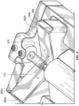
- a laser assembly 200 shown in FIG. 1 includes a conventional laser source 210, which generates a laser beam 120 of radiation.
- a mount 212a is coupled to orthogonal gantries 214a and 214b.
- One or more scanner mirrors within a scan head 212 are controlled by a processor-controlled drive unit or mechanism 213 to direct a laser beam 120 downwardly onto an assembly 250 that includes a thermoplastic workpiece 110 having a tubular part to be joined by welding.
- the drive unit 213 is controlled to adjust the positions of the scanner mirrors to move the laser beam 120 in a manner required to illuminate a prescribed weld zone on the top surface of the workpiece 110 fixed within the assembly 110.
- the optical reflecting surface(s) 262a, 262b of the optical reflector 260 can be a gold-plated mirror, which is configured to reflect laser energy 120 received.
- the angle of the surfaces 262a, 262b direct the laser energy 120 into surfaces of the workpiece 110 that are not directly accessible to the laser beam 120, which is fixed above the workpiece 110.
- the entire surface 262a, 262b does not have to be coated with an optically reflecting material.
- the other portions do not have to optically reflecting, such as the bottom or lowest portion 270 (best seen in FIGS. 2 and 5 ) directly below the workpiece 110 where no laser energy will be received.
- the portion 270 ( FIG. 2 ) directly underneath the workpiece 110 receive the reflected laser energy that bounce off of the optically reflecting surfaces 262a, 262b of the optical reflector 260. All this is to say that those skilled in the art will appreciate that only those surface portions where laser energy 120 will be directed need to be optically reflecting on the optical reflector 260.
- optical reflector 260 is non-moving and stationary at all times, including during setup of the assembly when the vertical distance, D, along the Z-axis between the underside of the workpiece 110 and the bottom or lowest point 270 of the optical reflector 260 directly below the underside of the workpiece 110 is being optimized.
- the first 262a and second 262b side surfaces of the fixed optical reflector 260 are arranged at a fixed obtuse angle ⁇ relative to each other.
- fixed it is meant that the angle ⁇ is unchanged even during setup before the laser weld is initiated.
- the assembly 250 has a height adjustment mechanism (not shown) that is configured to adjust a vertical distance D between the lowest point 270 of the optical reflector 260 and the underside of the workpiece 110 along a Z-axis that is transverse to a longitudinal axis (e.g., Y-axis) of the workpiece 110.
- the workpiece 110 is the adjustable part of the assembly 250, such that the workpiece 110 is moved up or down relative to the optical reflector 260 to change the vertical distance D (shown in FIG. 5 ).
- the workpiece 110 can be fixed, and the optical reflector 260 is adjusted up or down to change the vertical distance D; however, at all times the angle ⁇ between the reflecting surfaces 262a, 262b is constant and fixed.
- both the workpiece 110 and the optical reflector 260 can be adjusted along the Z-axis to change the distance D, for example, in an assembly 250 that has been retrofitted or modified to be configured according to the present disclosure.
- the first and second side surfaces 262a, 262b define a curve that is transverse to the longitudinal axis (e.g., Y-axis), and this curve forms the V- or U-shape of the optical reflector 260.
- this portion does not have to be strictly curved, because no laser energy will be directed to this portion, so its shape plays no role and therefore has no impact on optical reflection. Rather, it can be relatively flat or notched, depending on the design parameters and the angle of the reflecting surfaces 262a, 262b. It also does not have to be coated with an optically reflecting material, but for ease of manufacturability, coating the entire surface of the optical reflector 260 is desirable from that standpoint.
- the reflecting surface on the optical reflector 260 can be continuous, those skilled in the art will appreciate that the portion of the optical reflector 260 that sits directly underneath or below (relative to the incoming laser beam 120) the workpiece 110 does not directly receive the laser beam 120, and thus it is not necessary to render that part of the surface optically reflecting. While it is easier to manufacture a continuous surface, the present disclosure is not limited to a continuous surface.
- the flat side surfaces 262a, 262b of the optical reflector 260 can receive a reflective optical coating, whereas the portion 270 of the optical reflector 260 that sits directly beneath the workpiece 110 can lack a reflective optical coating.
- the optical reflector 260 can be composed of multiple parts, but all such parts being fixed and stationary to one another so that their angle ⁇ cannot be adjusted during setup of the assembly 250.
- the point is that there are at least two reflecting surfaces 262a, 262b that are fixed and stationary during the setup of the assembly 250, such that only a vertical adjustment of the distance D between the workpiece 110 and those reflecting surfaces 262a, 262b is necessary during setup.
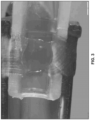
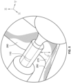
- FIGS. 3-4 illustrate photographs of cross-sections of thermoplastic sample workpieces joined by the welding apparatus and method disclosed herein, showing the high quality and consistently uniform weld circumferentially around the joined interfaces.
- the reflecting surfaces 262a, 262b were angled at an angle ⁇ of 133 degrees.
- the welding methods disclosed herein can be used for welding parts for any device requiring a circumferential weld, such as medical devices generally including medical delivery devices.
Landscapes
- Physics & Mathematics (AREA)
- Optics & Photonics (AREA)
- Engineering & Computer Science (AREA)
- Mechanical Engineering (AREA)
- Plasma & Fusion (AREA)
- Health & Medical Sciences (AREA)
- Electromagnetism (AREA)
- Toxicology (AREA)
- Laser Beam Processing (AREA)
- Lining Or Joining Of Plastics Or The Like (AREA)
Applications Claiming Priority (3)
| Application Number | Priority Date | Filing Date | Title |
|---|---|---|---|
| US201962801269P | 2019-02-05 | 2019-02-05 | |
| US16/352,104 US10926355B2 (en) | 2019-02-05 | 2019-03-13 | Systems and methods for laser-welding tubular components using a single, fixed optical reflector with multiple reflecting surfaces |
| PCT/US2020/016618 WO2020163363A1 (en) | 2019-02-05 | 2020-02-04 | System and method for laser-welding tubular components using a unitary, fixed optical reflector with multiple reflecting surfaces, and medical device |
Publications (2)
| Publication Number | Publication Date |
|---|---|
| EP3921142A1 EP3921142A1 (en) | 2021-12-15 |
| EP3921142B1 true EP3921142B1 (en) | 2024-11-06 |
Family
ID=71838159
Family Applications (1)
| Application Number | Title | Priority Date | Filing Date |
|---|---|---|---|
| EP20710344.1A Active EP3921142B1 (en) | 2019-02-05 | 2020-02-04 | System and method for laser-welding tubular components using a unitary, fixed optical reflector with multiple reflecting surfaces |
Country Status (7)
Families Citing this family (2)
| Publication number | Priority date | Publication date | Assignee | Title |
|---|---|---|---|---|
| DE102021200551A1 (de) * | 2021-01-21 | 2022-07-21 | LPKF WeldingQuipment GmbH | Verfahren und Vorrichtung zum Laserschweißen zweier thermoplastischer Bauteile |
| JP2022128431A (ja) * | 2021-02-22 | 2022-09-01 | デューケイン アイエーエス エルエルシー | 複数個の反射部分を用いワークピースのアクセス不能エリアにレーザビームを到達させてそのワークピースをレーザ熔接するシステム及び方法 |
Family Cites Families (68)
| Publication number | Priority date | Publication date | Assignee | Title |
|---|---|---|---|---|
| US3943324A (en) | 1970-12-14 | 1976-03-09 | Arthur D. Little, Inc. | Apparatus for forming refractory tubing |
| US3835912A (en) | 1973-06-25 | 1974-09-17 | S K S Ltd | Method of joining a filament to a metal rod |
| US3989778A (en) | 1975-12-17 | 1976-11-02 | W. R. Grace & Co. | Method of heat sealing thermoplastic sheets together using a split laser beam |
| CA1115220A (en) | 1978-10-23 | 1981-12-29 | Kazumi Ishigaki | Package of mechanical pencil refill leads |
| JPS55155314A (en) | 1979-05-21 | 1980-12-03 | Nippon Telegr & Teleph Corp <Ntt> | Connecting method of optical fiber and its connector |
| US4429211A (en) | 1982-08-02 | 1984-01-31 | United Technologies Corporation | Laser pipe welding system for nonstationary pipe |
| FR2547757B1 (fr) | 1983-06-27 | 1986-10-17 | Sciaky Sa | Procede et installation de soudage par point a faisceau laser |
| DE3822303A1 (de) | 1987-12-10 | 1989-06-22 | Birkle Gebhard | Vorrichtung zum optischen abtasten der oberflaeche eines objektes, dessen oberflaeche licht zu reflektieren oder streuen imstande ist und verfahren hierzu |
| US4794231A (en) | 1987-12-24 | 1988-12-27 | United Technologies Corporation | Method of and arrangement for laser welding |
| IT1239445B (it) | 1989-04-27 | 1993-11-02 | Molins Plc | Metodo ed apparecchiatura per la produzione di sigarette. |
| US5011282A (en) * | 1989-11-16 | 1991-04-30 | Amada Company, Limited | Laser beam path alignment apparatus for laser processing machines |
| US5049720A (en) | 1990-08-24 | 1991-09-17 | Fmc Corporation | Laser welding apparatus with sky window |
| JPH04143092A (ja) * | 1990-10-04 | 1992-05-18 | Brother Ind Ltd | レーザ加工装置 |
| DE4122093A1 (de) | 1991-07-01 | 1993-01-14 | Ver Energiewerke Ag | Verfahren zum einschweissen eines passstueckes innerhalb einer membranrohrwand eines dampfkessels |
| JP2740385B2 (ja) * | 1992-01-27 | 1998-04-15 | 松下電工株式会社 | 絶縁被覆導体のろう付け方法 |
| DE4235592C1 (de) | 1992-10-22 | 1994-01-27 | Aclas Lasertech Masch | Laser-Bearbeitungskopf und Zusatzeinrichtung für eine numerisch gesteuerte Werkzeugmaschine |
| US5478983A (en) | 1992-10-22 | 1995-12-26 | Rancourt; Yvon | Process and apparatus for welding or heat treating by laser |
| US5449879A (en) | 1993-10-07 | 1995-09-12 | Laser Machining, Inc. | Laser beam delivery system for heat treating work surfaces |
| US5601676A (en) | 1994-02-25 | 1997-02-11 | The Board Of Trustees Operating Michigan State University | Composite joining and repair |
| JP4142118B2 (ja) * | 1994-12-27 | 2008-08-27 | 古河電気工業株式会社 | 電子部品の製造方法及び絶縁電線の皮膜剥離処理方法 |
| JPH11245064A (ja) * | 1998-03-03 | 1999-09-14 | Nhk Spring Co Ltd | ディスク装置用サスペンションのレーザ溶接設備 |
| DE29900811U1 (de) | 1999-01-19 | 1999-03-18 | Sator Laser GmbH, 22525 Hamburg | Vorrichtung zum Verschweißen des Endes von rohrartigen Behältern aus Kunststoff, insbesondere von Tuben |
| EP0997261B9 (de) | 1999-01-28 | 2001-04-11 | Leister Process Technologies | Laserfügeverfahren und Vorrichtung zum Verbinden von verschiedenen Werkstücken aus Kunststoff oder Kunststoff mit anderen Materialien |
| JP3454773B2 (ja) * | 2000-02-29 | 2003-10-06 | 原子燃料工業株式会社 | 燃料棒の上部端栓溶接方法 |
| JP3961737B2 (ja) | 2000-02-29 | 2007-08-22 | 株式会社小糸製作所 | 車両用灯具およびその製造方法 |
| JP2003531013A (ja) | 2000-04-25 | 2003-10-21 | ディセトロニック・ライセンシング・アクチェンゲゼルシャフト | レーザビームを使用して物体に刻印する装置 |
| JP3810623B2 (ja) | 2000-08-28 | 2006-08-16 | 独立行政法人科学技術振興機構 | レーザによる包装用樹脂フィルムの接着方法 |
| JP3823065B2 (ja) | 2002-04-23 | 2006-09-20 | 愛三工業株式会社 | レーザ溶着方法 |
| JP2004063332A (ja) | 2002-07-30 | 2004-02-26 | Ichikoh Ind Ltd | 車両用灯具 |
| DE50200675D1 (de) | 2002-10-02 | 2004-08-26 | Leister Process Technologies S | Verfahren und Vorrichtung zum Bearbeiten von Werkstücken mittels eines Laserstrahls |
| US6705727B1 (en) | 2002-12-30 | 2004-03-16 | Bausch & Lomb Incorporated | Mechanism for rotationally moving a mirror |
| EP1477264A1 (en) | 2003-05-16 | 2004-11-17 | Lasag Ag | Apparatus for generating a rotating laser beam |
| US6835664B1 (en) | 2003-06-26 | 2004-12-28 | Micron Technology, Inc. | Methods of forming trenched isolation regions |
| EP1518664A1 (de) | 2003-09-20 | 2005-03-30 | Leister Process Technologies | Verfahren und Vorrichtung zum Verbinden von Bauteilen durch Laserstrahlung |
| JP2005125359A (ja) | 2003-10-23 | 2005-05-19 | Honda Motor Co Ltd | レーザビームによる溝の加工方法 |
| JP2007523763A (ja) | 2003-12-05 | 2007-08-23 | デュケーン・コーポレーション | 熱可塑性プラスチックのレーザー溶接用接合部設計 |
| FI116804B (fi) | 2004-05-18 | 2006-02-28 | Ekspansio Engineering Ltd Oy | Materiaalikappaleiden eri suuntiin osoittavien pintojen optinen tarkastus |
| JP2006168252A (ja) | 2004-12-17 | 2006-06-29 | Koito Mfg Co Ltd | 光線溶着装置及び光線溶着方法 |
| DE102005010193A1 (de) | 2005-03-05 | 2006-09-07 | Rehau Ag + Co | Verfahren und Vorrichtung zum Verbinden von Rohren |
| US20070045250A1 (en) | 2005-08-30 | 2007-03-01 | United Technologies Corporation | Method for manually laser welding metallic parts |
| JP4868887B2 (ja) | 2006-02-28 | 2012-02-01 | パナソニック電工Sunx株式会社 | 樹脂溶着方法、樹脂部品 |
| US8382709B2 (en) | 2006-09-25 | 2013-02-26 | Boston Scientific Scimed, Inc. | Designs for balloon welds |
| DE102007035717A1 (de) | 2006-12-27 | 2008-07-03 | Robert Bosch Gmbh | Laserstrahlschweißvorrichtung sowie Laserstrahlschweißverfahren |
| DE202007001346U1 (de) | 2007-01-24 | 2007-04-05 | H2B Photonics Gmbh | Einrichtung zum durchtrennenden Bearbeiten von Bauteilen aus sprödbrüchigem Material |
| JP5313232B2 (ja) * | 2007-05-04 | 2013-10-09 | ブランソン・ウルトラソニックス・コーポレーション | 吸収されなかった赤外レーザー光の再循環により赤外レーザー光の吸収を高めるプラスチック赤外線溶接 |
| US9168696B2 (en) | 2012-06-04 | 2015-10-27 | Sabic Global Technologies B.V. | Marked thermoplastic compositions, methods of making and articles comprising the same, and uses thereof |
| US7985941B2 (en) * | 2007-11-16 | 2011-07-26 | 3M Innovative Properties Company | Seamless laser ablated roll tooling |
| DE502008003181D1 (de) | 2008-08-28 | 2011-05-26 | Leister Process Tech | Verbindungs- oder Abzweigelement zum Verbinden mit einem Rohrendabschnitt im Laserdurchstrahlverfahren sowie Laserkopf und Verfahren zum Verbinden |
| DE102008042343A1 (de) | 2008-09-25 | 2010-04-01 | Robert Bosch Gmbh | Verfahren und Vorrichtung zum Bearbeiten und/oder Schweißen eines rotationssymmetrischen Werkstücks mit einem Laserstrahl |
| JP5316124B2 (ja) * | 2009-03-13 | 2013-10-16 | 日産自動車株式会社 | レーザー溶接装置 |
| DE102009021448B3 (de) | 2009-05-13 | 2010-07-22 | Fachhochschule Jena | Vorrichtung und Verfahren zur Umfangsbearbeitung eines Materialstranges mittels Laser |
| US8593701B2 (en) | 2009-09-04 | 2013-11-26 | Ricoh Company, Ltd. | Optical scanning device and image forming apparatus |
| US20110200802A1 (en) | 2010-02-16 | 2011-08-18 | Shenping Li | Laser Welding of Polymeric Materials |
| DE102010025375B4 (de) | 2010-06-28 | 2016-04-21 | Fraunhofer-Gesellschaft zur Förderung der angewandten Forschung e.V. | Laser-Bearbeitungsvorrichtung und Verfahren zum Laser-Bearbeiten zumindest eines Bauteils |
| US20120218652A1 (en) | 2011-02-24 | 2012-08-30 | Peak Flux, Inc. | Optical concentrator systems, devices and methods |
| DE102011007792A1 (de) * | 2011-04-20 | 2012-10-25 | Robert Bosch Gmbh | Laserstrahlschweißvorrichtung und Laserstrahlschweißverfahren |
| GB2491561A (en) | 2011-05-20 | 2012-12-12 | L C S Tech Ltd | Tamper proof seal |
| JP6024152B2 (ja) | 2012-03-29 | 2016-11-09 | 東洋製罐株式会社 | 容器及び蓋のレーザ溶着による密封方法 |
| WO2013172343A1 (ja) | 2012-05-16 | 2013-11-21 | 花王株式会社 | シート融着体の製造方法 |
| DE102012021602A1 (de) | 2012-11-06 | 2014-05-08 | Fresenius Medical Care Deutschland Gmbh | Vorrichtung zum Laserdurchstrahlschweißen und Verfahren zum Laserdurchstrahlschweißen |
| DE102013206892A1 (de) | 2013-04-17 | 2014-10-23 | OMRON Electronics Manufacturing of Germany G.m.b.H. | Reflektoranordnung, Lichtvorhang, Verfahren zum Einstellen der Reflektoranordnung, und Verfahren zum Montieren der Reflektoranordnung |
| WO2015161081A1 (en) * | 2014-04-17 | 2015-10-22 | Baxter International Inc. | Laser device for performing an annular circumferential welding on a workpiece using optical reflectors |
| DE102014108894B4 (de) | 2014-06-25 | 2020-08-06 | Ruhlamat Gmbh | Verfahren zum prozessgesteuerten Verschweißen von Materialien |
| CN104400996B (zh) | 2014-09-29 | 2017-01-18 | 山东新华医疗器械股份有限公司 | 软管与塞子的激光焊接装置及其焊接方法 |
| WO2016079275A1 (de) * | 2014-11-19 | 2016-05-26 | Trumpf Laser- Und Systemtechnik Gmbh | System zur asymmetrischen optischen strahlformung |
| DE102015119324A1 (de) * | 2015-11-10 | 2017-05-11 | Metzner Maschinenbau Gmbh | Vorrichtung zur Abisolierung von Kabeln |
| JP6014834B1 (ja) | 2016-07-01 | 2016-10-26 | 精電舎電子工業株式会社 | 光透過性樹脂のレーザ溶着方法および光透過性樹脂のレーザ溶着装置 |
| US10538036B2 (en) | 2016-09-15 | 2020-01-21 | Dukane Ias, Llc | Laser welding system and method using cooling mask to control the width of the weld |
-
2019
- 2019-03-13 US US16/352,104 patent/US10926355B2/en active Active
-
2020
- 2020-02-04 WO PCT/US2020/016618 patent/WO2020163363A1/en unknown
- 2020-02-04 JP JP2021545409A patent/JP7457720B2/ja active Active
- 2020-02-04 ES ES20710344T patent/ES3006234T3/es active Active
- 2020-02-04 PL PL20710344.1T patent/PL3921142T3/pl unknown
- 2020-02-04 EP EP20710344.1A patent/EP3921142B1/en active Active
- 2020-02-04 CN CN202080012683.6A patent/CN113396044A/zh active Pending
Also Published As
| Publication number | Publication date |
|---|---|
| ES3006234T3 (en) | 2025-03-18 |
| WO2020163363A1 (en) | 2020-08-13 |
| PL3921142T3 (pl) | 2025-03-31 |
| JP7457720B2 (ja) | 2024-03-28 |
| EP3921142A1 (en) | 2021-12-15 |
| JP2022519277A (ja) | 2022-03-22 |
| CN113396044A (zh) | 2021-09-14 |
| US20200246916A1 (en) | 2020-08-06 |
| US10926355B2 (en) | 2021-02-23 |
Similar Documents
| Publication | Publication Date | Title |
|---|---|---|
| US20170182592A1 (en) | Systems and methods for welding workpieces using a laser beam and optical reflectors | |
| EP3921142B1 (en) | System and method for laser-welding tubular components using a unitary, fixed optical reflector with multiple reflecting surfaces | |
| US11679557B2 (en) | Processing machines and methods for heating a powder to produce three-dimensional components | |
| CN106583726B (zh) | 激光多光束熔覆装置 | |
| JP2020025985A (ja) | マルチビームはんだ付けシステムおよびマルチビームはんだ付け方法 | |
| EP3238609B1 (en) | Fundus image forming device | |
| KR20110028587A (ko) | 다중 헤드 레이저 가공 시스템에서 공통의 척 이동 방향을 따른 헤드간 옵셋 의 제거 | |
| US11931823B2 (en) | Systems and methods for laser-welding a workpiece with a laser beam that reaches inaccessible areas of the workpiece using multiple reflecting parts | |
| CN112548324A (zh) | 激光焊接方法和用于激光焊接的设备 | |
| US11819940B2 (en) | Systems and methods for laser-welding a workpiece with a laser beam that reaches inaccessible areas of the workpiece using multiple reflecting parts | |
| EP4046740A1 (en) | System and method for laser-welding a workpiece with a laser beam that reaches inaccessible areas of the workpiece using multiple reflecting parts | |
| US6896384B2 (en) | Laser beam translation system and method | |
| JP2020105055A (ja) | ガラスの曲げ加工方法および加工装置 | |
| US20240399501A1 (en) | Device for laser deposition welding with coaxial deposition material feed and with distance measuring device | |
| EP4325270B1 (en) | Optical scanning device and manufacturing method | |
| CN116161859B (zh) | 一种玻璃管的激光焊接方法 | |
| JP2006106703A (ja) | レーザービーム送出システムの安定性のためにビーム整形を用いる補償器光学系、及び横方向ビームドリフトによるエネルギー分布形状歪みを補正するための径方向非対称ビーム形成素子 | |
| US20220395925A1 (en) | Method for laser machining a workpiece and associated laser machining system | |
| EP4558301A2 (en) | Apparatus and method for wire laser deposition by ring shaped focus using multi-split beam | |
| WO2020184516A1 (ja) | 光走査装置、光走査方法、及びリチウムイオン電池の製造方法 | |
| CN119781179A (zh) | 一种激光器光学模块、激光焊接头以及激光焊接方法 | |
| CN117130096A (zh) | 一种光纤熔接装置及熔接方法 | |
| JP2018196750A (ja) | 眼底像形成装置 | |
| JP2004170626A (ja) | 光学的ビーム走査装置 |
Legal Events
| Date | Code | Title | Description |
|---|---|---|---|
| STAA | Information on the status of an ep patent application or granted ep patent |
Free format text: STATUS: UNKNOWN |
|
| STAA | Information on the status of an ep patent application or granted ep patent |
Free format text: STATUS: THE INTERNATIONAL PUBLICATION HAS BEEN MADE |
|
| PUAI | Public reference made under article 153(3) epc to a published international application that has entered the european phase |
Free format text: ORIGINAL CODE: 0009012 |
|
| STAA | Information on the status of an ep patent application or granted ep patent |
Free format text: STATUS: REQUEST FOR EXAMINATION WAS MADE |
|
| 17P | Request for examination filed |
Effective date: 20210826 |
|
| AK | Designated contracting states |
Kind code of ref document: A1 Designated state(s): AL AT BE BG CH CY CZ DE DK EE ES FI FR GB GR HR HU IE IS IT LI LT LU LV MC MK MT NL NO PL PT RO RS SE SI SK SM TR |
|
| DAV | Request for validation of the european patent (deleted) | ||
| DAX | Request for extension of the european patent (deleted) | ||
| STAA | Information on the status of an ep patent application or granted ep patent |
Free format text: STATUS: EXAMINATION IS IN PROGRESS |
|
| 17Q | First examination report despatched |
Effective date: 20231205 |
|
| GRAP | Despatch of communication of intention to grant a patent |
Free format text: ORIGINAL CODE: EPIDOSNIGR1 |
|
| STAA | Information on the status of an ep patent application or granted ep patent |
Free format text: STATUS: GRANT OF PATENT IS INTENDED |
|
| RIC1 | Information provided on ipc code assigned before grant |
Ipc: B23K 103/00 20060101ALN20240624BHEP Ipc: B23K 101/06 20060101ALN20240624BHEP Ipc: B29K 101/12 20060101ALN20240624BHEP Ipc: B23K 26/324 20140101ALI20240624BHEP Ipc: B23K 26/282 20140101ALI20240624BHEP Ipc: B23K 26/10 20060101ALI20240624BHEP Ipc: B23K 26/08 20140101ALI20240624BHEP Ipc: B23K 26/06 20140101ALI20240624BHEP Ipc: B29C 65/16 20060101AFI20240624BHEP |
|
| INTG | Intention to grant announced |
Effective date: 20240710 |
|
| GRAS | Grant fee paid |
Free format text: ORIGINAL CODE: EPIDOSNIGR3 |
|
| GRAA | (expected) grant |
Free format text: ORIGINAL CODE: 0009210 |
|
| STAA | Information on the status of an ep patent application or granted ep patent |
Free format text: STATUS: THE PATENT HAS BEEN GRANTED |
|
| AK | Designated contracting states |
Kind code of ref document: B1 Designated state(s): AL AT BE BG CH CY CZ DE DK EE ES FI FR GB GR HR HU IE IS IT LI LT LU LV MC MK MT NL NO PL PT RO RS SE SI SK SM TR |
|
| REG | Reference to a national code |
Ref country code: GB Ref legal event code: FG4D |
|
| REG | Reference to a national code |
Ref country code: CH Ref legal event code: EP |
|
| REG | Reference to a national code |
Ref country code: DE Ref legal event code: R096 Ref document number: 602020040770 Country of ref document: DE |
|
| REG | Reference to a national code |
Ref country code: IE Ref legal event code: FG4D |
|
| P01 | Opt-out of the competence of the unified patent court (upc) registered |
Free format text: CASE NUMBER: APP_60799/2024 Effective date: 20241112 |
|
| REG | Reference to a national code |
Ref country code: NL Ref legal event code: FP |
|
| REG | Reference to a national code |
Ref country code: LT Ref legal event code: MG9D |
|
| PGFP | Annual fee paid to national office [announced via postgrant information from national office to epo] |
Ref country code: NL Payment date: 20250218 Year of fee payment: 6 |
|
| REG | Reference to a national code |
Ref country code: ES Ref legal event code: FG2A Ref document number: 3006234 Country of ref document: ES Kind code of ref document: T3 Effective date: 20250318 |
|
| PG25 | Lapsed in a contracting state [announced via postgrant information from national office to epo] |
Ref country code: IS Free format text: LAPSE BECAUSE OF FAILURE TO SUBMIT A TRANSLATION OF THE DESCRIPTION OR TO PAY THE FEE WITHIN THE PRESCRIBED TIME-LIMIT Effective date: 20250306 Ref country code: PT Free format text: LAPSE BECAUSE OF FAILURE TO SUBMIT A TRANSLATION OF THE DESCRIPTION OR TO PAY THE FEE WITHIN THE PRESCRIBED TIME-LIMIT Effective date: 20250306 Ref country code: HR Free format text: LAPSE BECAUSE OF FAILURE TO SUBMIT A TRANSLATION OF THE DESCRIPTION OR TO PAY THE FEE WITHIN THE PRESCRIBED TIME-LIMIT Effective date: 20241106 |
|
| PGFP | Annual fee paid to national office [announced via postgrant information from national office to epo] |
Ref country code: DE Payment date: 20250218 Year of fee payment: 6 |
|
| PG25 | Lapsed in a contracting state [announced via postgrant information from national office to epo] |
Ref country code: FI Free format text: LAPSE BECAUSE OF FAILURE TO SUBMIT A TRANSLATION OF THE DESCRIPTION OR TO PAY THE FEE WITHIN THE PRESCRIBED TIME-LIMIT Effective date: 20241106 |
|
| PG25 | Lapsed in a contracting state [announced via postgrant information from national office to epo] |
Ref country code: BG Free format text: LAPSE BECAUSE OF FAILURE TO SUBMIT A TRANSLATION OF THE DESCRIPTION OR TO PAY THE FEE WITHIN THE PRESCRIBED TIME-LIMIT Effective date: 20241106 |
|
| PG25 | Lapsed in a contracting state [announced via postgrant information from national office to epo] |
Ref country code: NO Free format text: LAPSE BECAUSE OF FAILURE TO SUBMIT A TRANSLATION OF THE DESCRIPTION OR TO PAY THE FEE WITHIN THE PRESCRIBED TIME-LIMIT Effective date: 20250206 |
|
| PG25 | Lapsed in a contracting state [announced via postgrant information from national office to epo] |
Ref country code: LV Free format text: LAPSE BECAUSE OF FAILURE TO SUBMIT A TRANSLATION OF THE DESCRIPTION OR TO PAY THE FEE WITHIN THE PRESCRIBED TIME-LIMIT Effective date: 20241106 Ref country code: GR Free format text: LAPSE BECAUSE OF FAILURE TO SUBMIT A TRANSLATION OF THE DESCRIPTION OR TO PAY THE FEE WITHIN THE PRESCRIBED TIME-LIMIT Effective date: 20250207 |
|
| PGFP | Annual fee paid to national office [announced via postgrant information from national office to epo] |
Ref country code: CH Payment date: 20250301 Year of fee payment: 6 Ref country code: AT Payment date: 20250219 Year of fee payment: 6 Ref country code: BE Payment date: 20250218 Year of fee payment: 6 |
|
| PGFP | Annual fee paid to national office [announced via postgrant information from national office to epo] |
Ref country code: FR Payment date: 20250224 Year of fee payment: 6 Ref country code: PL Payment date: 20250128 Year of fee payment: 6 Ref country code: CZ Payment date: 20250127 Year of fee payment: 6 |
|
| PGFP | Annual fee paid to national office [announced via postgrant information from national office to epo] |
Ref country code: IT Payment date: 20250227 Year of fee payment: 6 Ref country code: GB Payment date: 20250220 Year of fee payment: 6 |
|
| PG25 | Lapsed in a contracting state [announced via postgrant information from national office to epo] |
Ref country code: RS Free format text: LAPSE BECAUSE OF FAILURE TO SUBMIT A TRANSLATION OF THE DESCRIPTION OR TO PAY THE FEE WITHIN THE PRESCRIBED TIME-LIMIT Effective date: 20250206 |
|
| PG25 | Lapsed in a contracting state [announced via postgrant information from national office to epo] |
Ref country code: SM Free format text: LAPSE BECAUSE OF FAILURE TO SUBMIT A TRANSLATION OF THE DESCRIPTION OR TO PAY THE FEE WITHIN THE PRESCRIBED TIME-LIMIT Effective date: 20241106 |
|
| PG25 | Lapsed in a contracting state [announced via postgrant information from national office to epo] |
Ref country code: DK Free format text: LAPSE BECAUSE OF FAILURE TO SUBMIT A TRANSLATION OF THE DESCRIPTION OR TO PAY THE FEE WITHIN THE PRESCRIBED TIME-LIMIT Effective date: 20241106 |
|
| PGFP | Annual fee paid to national office [announced via postgrant information from national office to epo] |
Ref country code: ES Payment date: 20250331 Year of fee payment: 6 |
|
| PG25 | Lapsed in a contracting state [announced via postgrant information from national office to epo] |
Ref country code: EE Free format text: LAPSE BECAUSE OF FAILURE TO SUBMIT A TRANSLATION OF THE DESCRIPTION OR TO PAY THE FEE WITHIN THE PRESCRIBED TIME-LIMIT Effective date: 20241106 |
|
| PG25 | Lapsed in a contracting state [announced via postgrant information from national office to epo] |
Ref country code: RO Free format text: LAPSE BECAUSE OF FAILURE TO SUBMIT A TRANSLATION OF THE DESCRIPTION OR TO PAY THE FEE WITHIN THE PRESCRIBED TIME-LIMIT Effective date: 20241106 |
|
| PG25 | Lapsed in a contracting state [announced via postgrant information from national office to epo] |
Ref country code: SK Free format text: LAPSE BECAUSE OF FAILURE TO SUBMIT A TRANSLATION OF THE DESCRIPTION OR TO PAY THE FEE WITHIN THE PRESCRIBED TIME-LIMIT Effective date: 20241106 |