EP3915308B1 - Bandwidth part operation and downlink or uplink positioning reference signal scheme - Google Patents
Bandwidth part operation and downlink or uplink positioning reference signal scheme Download PDFInfo
- Publication number
- EP3915308B1 EP3915308B1 EP20705862.9A EP20705862A EP3915308B1 EP 3915308 B1 EP3915308 B1 EP 3915308B1 EP 20705862 A EP20705862 A EP 20705862A EP 3915308 B1 EP3915308 B1 EP 3915308B1
- Authority
- EP
- European Patent Office
- Prior art keywords
- prs
- bandwidth
- frequency domain
- domain allocation
- cases
- Prior art date
- Legal status (The legal status is an assumption and is not a legal conclusion. Google has not performed a legal analysis and makes no representation as to the accuracy of the status listed.)
- Active
Links
Images


Classifications
-
- H—ELECTRICITY
- H04—ELECTRIC COMMUNICATION TECHNIQUE
- H04L—TRANSMISSION OF DIGITAL INFORMATION, e.g. TELEGRAPHIC COMMUNICATION
- H04L5/00—Arrangements affording multiple use of the transmission path
- H04L5/0001—Arrangements for dividing the transmission path
- H04L5/0003—Two-dimensional division
- H04L5/0005—Time-frequency
- H04L5/0007—Time-frequency the frequencies being orthogonal, e.g. OFDM(A) or DMT
- H04L5/001—Time-frequency the frequencies being orthogonal, e.g. OFDM(A) or DMT the frequencies being arranged in component carriers
-
- H—ELECTRICITY
- H04—ELECTRIC COMMUNICATION TECHNIQUE
- H04L—TRANSMISSION OF DIGITAL INFORMATION, e.g. TELEGRAPHIC COMMUNICATION
- H04L5/00—Arrangements affording multiple use of the transmission path
- H04L5/003—Arrangements for allocating sub-channels of the transmission path
- H04L5/0048—Allocation of pilot signals, i.e. of signals known to the receiver
-
- H—ELECTRICITY
- H04—ELECTRIC COMMUNICATION TECHNIQUE
- H04L—TRANSMISSION OF DIGITAL INFORMATION, e.g. TELEGRAPHIC COMMUNICATION
- H04L5/00—Arrangements affording multiple use of the transmission path
- H04L5/0091—Signalling for the administration of the divided path, e.g. signalling of configuration information
-
- H—ELECTRICITY
- H04—ELECTRIC COMMUNICATION TECHNIQUE
- H04W—WIRELESS COMMUNICATION NETWORKS
- H04W24/00—Supervisory, monitoring or testing arrangements
- H04W24/08—Testing, supervising or monitoring using real traffic
-
- H—ELECTRICITY
- H04—ELECTRIC COMMUNICATION TECHNIQUE
- H04W—WIRELESS COMMUNICATION NETWORKS
- H04W4/00—Services specially adapted for wireless communication networks; Facilities therefor
- H04W4/02—Services making use of location information
- H04W4/029—Location-based management or tracking services
-
- H—ELECTRICITY
- H04—ELECTRIC COMMUNICATION TECHNIQUE
- H04W—WIRELESS COMMUNICATION NETWORKS
- H04W4/00—Services specially adapted for wireless communication networks; Facilities therefor
- H04W4/70—Services for machine-to-machine communication [M2M] or machine type communication [MTC]
-
- H—ELECTRICITY
- H04—ELECTRIC COMMUNICATION TECHNIQUE
- H04W—WIRELESS COMMUNICATION NETWORKS
- H04W64/00—Locating users or terminals or network equipment for network management purposes, e.g. mobility management
-
- H—ELECTRICITY
- H04—ELECTRIC COMMUNICATION TECHNIQUE
- H04W—WIRELESS COMMUNICATION NETWORKS
- H04W72/00—Local resource management
- H04W72/04—Wireless resource allocation
-
- H—ELECTRICITY
- H04—ELECTRIC COMMUNICATION TECHNIQUE
- H04W—WIRELESS COMMUNICATION NETWORKS
- H04W72/00—Local resource management
- H04W72/04—Wireless resource allocation
- H04W72/044—Wireless resource allocation based on the type of the allocated resource
- H04W72/0453—Resources in frequency domain, e.g. a carrier in FDMA
-
- H—ELECTRICITY
- H04—ELECTRIC COMMUNICATION TECHNIQUE
- H04W—WIRELESS COMMUNICATION NETWORKS
- H04W72/00—Local resource management
- H04W72/04—Wireless resource allocation
- H04W72/044—Wireless resource allocation based on the type of the allocated resource
- H04W72/0457—Variable allocation of band or rate
-
- H—ELECTRICITY
- H04—ELECTRIC COMMUNICATION TECHNIQUE
- H04W—WIRELESS COMMUNICATION NETWORKS
- H04W72/00—Local resource management
- H04W72/20—Control channels or signalling for resource management
- H04W72/23—Control channels or signalling for resource management in the downlink direction of a wireless link, i.e. towards a terminal
- H04W72/231—Control channels or signalling for resource management in the downlink direction of a wireless link, i.e. towards a terminal the control data signalling from the layers above the physical layer, e.g. RRC or MAC-CE signalling
-
- H—ELECTRICITY
- H04—ELECTRIC COMMUNICATION TECHNIQUE
- H04W—WIRELESS COMMUNICATION NETWORKS
- H04W72/00—Local resource management
- H04W72/20—Control channels or signalling for resource management
- H04W72/23—Control channels or signalling for resource management in the downlink direction of a wireless link, i.e. towards a terminal
- H04W72/232—Control channels or signalling for resource management in the downlink direction of a wireless link, i.e. towards a terminal the control data signalling from the physical layer, e.g. DCI signalling
-
- H—ELECTRICITY
- H04—ELECTRIC COMMUNICATION TECHNIQUE
- H04W—WIRELESS COMMUNICATION NETWORKS
- H04W8/00—Network data management
- H04W8/22—Processing or transfer of terminal data, e.g. status or physical capabilities
- H04W8/24—Transfer of terminal data
-
- H—ELECTRICITY
- H04—ELECTRIC COMMUNICATION TECHNIQUE
- H04L—TRANSMISSION OF DIGITAL INFORMATION, e.g. TELEGRAPHIC COMMUNICATION
- H04L5/00—Arrangements affording multiple use of the transmission path
- H04L5/0001—Arrangements for dividing the transmission path
- H04L5/0014—Three-dimensional division
- H04L5/0016—Time-frequency-code
-
- H—ELECTRICITY
- H04—ELECTRIC COMMUNICATION TECHNIQUE
- H04W—WIRELESS COMMUNICATION NETWORKS
- H04W4/00—Services specially adapted for wireless communication networks; Facilities therefor
- H04W4/02—Services making use of location information
Definitions
- the present application relates generally to wireless communications, and more specifically to bandwidth part considerations for uplink and downlink positioning reference signals.
- a wireless communications network may implement techniques to keep track of the positioning of a UE in the wireless communications network.
- the UE may transmit or receive positioning reference signals to or from base stations, which the network may use to determine the positioning of the UE.
- the wireless communications network may support UEs with different bandwidth capabilities. Conventional techniques to assign resources for a positioning reference signal are deficient when assigning resources to UEs with varying bandwidth capabilities.
- US 2017/238298 A1 discloses methods, systems, and devices for wireless communication.
- a UE and a base station may establish narrowband communications.
- the base station may configure positioning reference signal (PRS) resources based at least in part on wideband or narrowband transmissions, and a UE may receive the PRS transmissions over one or more narrowband regions.
- the UE may determine PRS resources and receive portions of wideband PRS transmissions that are transmitted in one or more narrowband regions of the system bandwidth.
- the base station may configure PRS resources separately for narrowband devices, such as according to a bandwidth of the narrowband devices or with a single PRS tone per symbol compared to two PRS tones per symbol that may be used for wideband PRS transmissions.
- the base station may perform positioning measurements for a UE based at least in part on timing of uplink transmissions from the UE.
- US 2018/217228 A1 discloses methods for aiding a mobile device in the acquisition of PRSs transmitted in a cellular network in support of OTDOA positioning.
- a mobile device receives an offset parameter from a location server indicative of a difference in timing between transmission of a first PRS positioning occasion for a reference cell and transmission of a second PRS positioning occasion for a neighboring cell that supports multiple PRS configurations, where the second PRS positioning occasion is for a PRS configuration with a longest periodicity.
- the mobile device may determine an expected timing of PRS positioning occasions for other PRS configurations for the neighboring cell based on the offset parameter and may measure a Reference Signal Time Difference for the neighboring cell using the expected timing.
- EP 3 490 319 A1 falls under Article 54(3) EPC and discloses determining at a network entity a common frequency resource allocation grid in a cell.
- the method may also include configuring at the network entity a frequency location of a bandwidth part of a user equipment within the cell. The frequency location of the bandwidth part may be offset from a reference point of the common frequency resource allocation grid.
- the method may include determining a size of one or more of a plurality of resource block groups within the bandwidth part of the user equipment based on the frequency location of the bandwidth part and the reference point. Further, the method may include transmit downlink control information from the network entity to the user equipment.
- a user equipment (UE) in a wireless communications system may communicate with one or more transmission reception points, such as base stations.
- Each transmission reception point may provide a cell which extends within a coverage area of the transmission reception point.
- the UE may move within the coverage area, and the cell may provide wireless communications (e.g., New Radio (NR) communications, or others) to the UE.
- NR New Radio
- the UE may be allocated a bandwidth part (BWP) to communicate with a serving base station.
- the BWP may be a contiguous set of physical resource blocks (PRBs) on a given wireless communications carrier.
- PRBs physical resource blocks
- Each BWP may be associated with a numerology, where a subcarrier spacing (SCS), symbol duration, and cyclic prefix length used for the BWP is based on the numerology.
- the PRBs may be selected from a contiguous subset of common resource blocks, which are allocated or assigned by a base station to served UEs.
- the UE may have one active BWP for uplink transmissions and one active BWP for downlink communications. Generally, the UE may transmit and receive within the frequency ranges of the active BWPs, and the UE may not be configured to transmit or expected to receive outside of the active BWPs for uplink and downlink respectively.
- a base station configuring a BWP for the UE may indicate the start of the BWP (e.g., in frequency) based on an offset from a common reference point in the carrier.
- the common reference point may correspond to a reference resource block, a start, end, or center point of the carrier, etc.
- a serving base station of a UE may keep track of the location or positioning of the UE.
- Various positioning techniques may be used to track the UE.
- the UE may be configured to transmit to an uplink positioning reference signal (PRS) to the serving base station and one or more neighboring base stations, or the UE may be configured to receive a downlink PRS from the serving base station and one or more neighboring base stations.
- PRS uplink positioning reference signal
- the base station and the neighboring base stations may exchange, for example via backhaul links, information associated with the receipt of the uplink PRS, such as reference signal time difference (RSTD) measurements made by the UE.
- the network e.g., including the base stations
- the UE may receive a PRS from each of one or more base stations.
- UE may estimate its positioning based on the measurements, for example based on reference signal time difference (RSTD) measurements. Additionally, or alternatively, the UE may transmit measurement reports for the one or more PRSs to a serving base station.
- a positioning technique may be UE-based or UE-assisted. In UE-based positioning, the UE may perform the positioning estimation without feeding back RSTD measurements to the network (e.g., via a base station). In UE-assisted positioning, the UE may provide the RSTD measurements, and the network may perform the positioning estimation using the RSTD measurements.
- a UE may be configured for a UE-based mode, a UE-assisted mode, or a mode which incorporates aspects of both. The used positioning mode may be based on a connection initialization configuration, downlink control information, a Medium Access Control (MAC) control element (CE), etc.
- MAC Medium Access Control
- CE Medium Access Control
- UEs in a carrier may be assigned resources uniformly.
- UEs in the carrier may have similar bandwidth capabilities, such that the base station may uniformly assign resources for an uplink PRS or a downlink PRS.
- some wireless devices such as UEs, machine-type-communications (MTC) devices, and others, may have different capabilities for the amount of bandwidth the wireless devices are able to use.
- MTC machine-type-communications
- the BWP resource assignment schemes described above may provide flexibility in bandwidth assignment such that two UEs may not use the same BWP or even overlap in assigned frequency resources, even if the two UEs are in the same carrier. Therefore, a UE and a base station as described herein, as well as other wireless devices, may implement techniques which consider BWP implementations for uplink and downlink PRS transmissions.
- the UE may be indicated a PRS bandwidth for receiving a downlink PRS or transmitting an uplink PRS.
- the PRS bandwidth may at least partially overlap with one or more configured active BWPs for the UE.
- a downlink PRS transmitted by a serving or neighboring cell can be configured to be transmitted in the PRS bandwidth.
- the PRS bandwidth may be configured based on a common reference point in the carrier.
- a start and an end resource block of the frequency domain allocation for the PRS bandwidth may be defined with respect to the common reference point (e.g., a reference resource block).
- the subcarrier spacing for the PRS bandwidth may be different than the subcarrier spacing for the active BWP.
- the start and end resource block of the frequency domain allocation for the PRS bandwidth may be defined with respect to the start of the component carrier.
- the subcarrier spacing for the PRS bandwidth may be the same as the subcarrier spacing of the active BWP.
- the scrambling sequence may be based on the reference point.
- two base stations may have PRS bandwidths configured based on the two different examples. For example, a first base station may have a first PRS bandwidth for downlink PRS based on the first example (e.g., with respect to the reference point), and the second base station may have a second PRS bandwidth for downlink PRS based on the second example (e.g., with respect to the start of the component carrier).
- the two base stations may each configure a PRS bandwidth with reference to the reference point or with reference to the start of the component carrier.
- a first and second PRS transmission to a respective first and second base station may either both be based on a common reference point, or both may be based on the BWP start. Or, in some cases, one uplink PRS transmission may be based on the common reference point while the other is based on the BWP start.
- the UE may be configured to measure a larger bandwidth than just the intersection of the PRS bandwidth with the active BWP.
- the PRS bandwidth may extend beyond the frequency range of the active BWP.
- Whether the UE is configured to make a measurement outside of the active BWP may be determined at the UE based on an indication from a base station, based on whether the positioning technique is UE-based or UE-assisted, determined at the base station based on an indication of UE capability, based on whether a sufficient gap before or after is provided to the UE (e.g., which may be based on UE capability), or any combination thereof.
- the UE may be configured to measure PRS transmitted by multiple base stations.
- the active BWP (e.g., corresponding to the serving base station) may change dynamically. In this example, the intersection of the active BWP with each PRS may be different. This may lead to different accuracy for each of the PRS measurements.
- the active BWP may not be expected or configured to change within until certain conditions have been met. For example, the active BWP may not change during reception of a specific PRS occasion or a PRS occasion group. In some examples, the active BWP may not be configured to change during multiple consecutive PRS occasions or during an occasion group inside a configured time window.
- the active BWP may not be configured to change during multiple PRS occasions or an occasion group until at least all configured base stations have been measured.
- the active BWP may change, but the UE may not be expected or configured to change the PRS-measured bandwidth based on the active BWP change. For example, the UE may first receive a PRS which has an intersection of a first BWP equal to the bandwidth of the first BWP. The active BWP then changes to a second BWP which has a smaller bandwidth, and the UE receives a second PRS. The UE may still measure the larger PRS corresponding to the bandwidth of the first BWP. In some cases, the UE may have a measurement gap before or after the second PRS.
- the UE may assume the same set of antenna ports are transmitted. In some cases, the UE may measure on the PRS bandwidth which intersects with a first active bandwidth part, with a second active bandwidth part, or with both the first and the second active bandwidth parts. In some cases, there may be a UE capability to indicate the maximum bandwidth of the PRS resource that the UE can process if the PRS resource is supported to span across multiple component carriers. In some cases, the time domain gaps (e.g., measurement gaps) for a measurement across multiple component carriers may be greater (e.g., longer) then a measurement gap for a measurement in a single component carrier.
- the time domain gaps e.g., measurement gaps
- the configured PRS bandwidth spans multiple active BWPs in a component carrier, there may be a corresponding UE capability which indicates whether the UE can measure PRS on multiple active BWPs.
- the UE capability may indicate the maximum bandwidth of the PRS resource that the UE may process in the case that the PRS configuration is supported to span across multiple active BWPs.
- aspects of the disclosure are initially described in the context of a wireless communications system. Aspects of the disclosure are further illustrated by and described with reference to apparatus diagrams, system diagrams, and flowcharts that relate to bandwidth part considerations for uplink and downlink positioning reference signals.
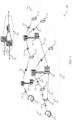
- FIG. 1 illustrates an example of a wireless communications system 100 that supports bandwidth part considerations for uplink and downlink positioning reference signals in accordance with aspects of the present disclosure.
- the wireless communications system 100 includes base stations 105, UEs 115, and a core network 130.
- the wireless communications system 100 may be a Long Term Evolution (LTE) network, an LTE-Advanced (LTE-A) network, an LTE-A Pro network, or a New Radio (NR) network.
- LTE Long Term Evolution
- LTE-A LTE-Advanced
- LTE-A Pro LTE-A Pro
- NR New Radio
- wireless communications system 100 may support enhanced broadband communications, ultra-reliable (e.g., mission critical) communications, low latency communications, or communications with low-cost and low-complexity devices.
- ultra-reliable e.g., mission critical
- Base stations 105 may wirelessly communicate with UEs 115 via one or more base station antennas.
- Base stations 105 described herein may include or may be referred to by those skilled in the art as a base transceiver station, a radio base station, an access point, a radio transceiver, a NodeB, an eNodeB (eNB), a next-generation NodeB or giga-NodeB (either of which may be referred to as a gNB), a Home NodeB, a Home eNodeB, or some other suitable terminology.
- Wireless communications system 100 may include base stations 105 of different types (e.g., macro or small cell base stations).
- the UEs 115 described herein may be able to communicate with various types of base stations 105 and network equipment including macro eNBs, small cell eNBs, gNBs, relay base stations, and the like.
- Each base station 105 may be associated with a particular geographic coverage area 110 in which communications with various UEs 115 is supported. Each base station 105 may provide communication coverage for a respective geographic coverage area 110 via communication links 125, and communication links 125 between a base station 105 and a UE 115 may utilize one or more carriers. Communication links 125 shown in wireless communications system 100 may include uplink transmissions from a UE 115 to a base station 105, or downlink transmissions from a base station 105 to a UE 115. Downlink transmissions may also be called forward link transmissions while uplink transmissions may also be called reverse link transmissions.
- the geographic coverage area 110 for a base station 105 may be divided into sectors making up a portion of the geographic coverage area 110, and each sector may be associated with a cell.
- each base station 105 may provide communication coverage for a macro cell, a small cell, a hot spot, or other types of cells, or various combinations thereof.
- a base station 105 may be movable and therefore provide communication coverage for a moving geographic coverage area 110.
- different geographic coverage areas 110 associated with different technologies may overlap, and overlapping geographic coverage areas 110 associated with different technologies may be supported by the same base station 105 or by different base stations 105.
- the wireless communications system 100 may include, for example, a heterogeneous LTE/LTE-A/LTE-A Pro or NR network in which different types of base stations 105 provide coverage for various geographic coverage areas 110.
- UEs 115 may be dispersed throughout the wireless communications system 100, and each UE 115 may be stationary or mobile.
- a UE 115 may also be referred to as a mobile device, a wireless device, a remote device, a handheld device, or a subscriber device, or some other suitable terminology, where the "device” may also be referred to as a unit, a station, a terminal, or a client.
- a UE 115 may also be a personal electronic device such as a cellular phone, a personal digital assistant (PDA), a tablet computer, a laptop computer, or a personal computer.
- PDA personal digital assistant
- Some UEs 115 may be configured to employ operating modes that reduce power consumption, such as half-duplex communications (e.g., a mode that supports one-way communication via transmission or reception, but not transmission and reception simultaneously). In some examples half-duplex communications may be performed at a reduced peak rate. Other power conservation techniques for UEs 115 include entering a power saving "deep sleep" mode when not engaging in active communications, or operating over a limited bandwidth (e.g., according to narrowband communications). In some cases, UEs 115 may be designed to support critical functions (e.g., mission critical functions), and a wireless communications system 100 may be configured to provide ultra-reliable communications for these functions.
- critical functions e.g., mission critical functions
- a UE 115 may also be able to communicate directly with other UEs 115 (e.g., using a peer-to-peer (P2P) or device-to-device (D2D) protocol).
- P2P peer-to-peer
- D2D device-to-device
- One or more of a group of UEs 115 utilizing D2D communications may be within the geographic coverage area 110 of a base station 105.
- Other UEs 115 in such a group may be outside the geographic coverage area 110 of a base station 105, or be otherwise unable to receive transmissions from a base station 105.
- groups of UEs 115 communicating via D2D communications may utilize a one-to-many (1:M) system in which each UE 115 transmits to every other UE 115 in the group.
- a base station 105 facilitates the scheduling of resources for D2D communications.
- D2D communications are carried out between UEs 115 without the involvement of a base station
- Base stations 105 may communicate with the core network 130 and with one another.
- base stations 105 may interface with the core network 130 through backhaul links 132 (e.g., via an S1, N2, N3, or other interface).
- Base stations 105 may communicate with one another over backhaul links 134 (e.g., via an X2, Xn, or other interface) either directly (e.g., directly between base stations 105) or indirectly (e.g., via core network 130).
- the core network 130 may provide user authentication, access authorization, tracking, Internet Protocol (IP) connectivity, and other access, routing, or mobility functions.
- the core network 130 may be an evolved packet core (EPC), which may include at least one mobility management entity (MME), at least one serving gateway (S-GW), and at least one Packet Data Network (PDN) gateway (P-GW).
- the MME may manage non-access stratum (e.g., control plane) functions such as mobility, authentication, and bearer management for UEs 115 served by base stations 105 associated with the EPC.
- User IP packets may be transferred through the S-GW, which itself may be connected to the P-GW.
- the P-GW may provide IP address allocation as well as other functions.
- the P-GW may be connected to the network operators IP services.
- the operators IP services may include access to the Internet, Intranet(s), an IP Multimedia Subsystem (IMS), or a Packet-Switched (PS) Streaming Service.
- IMS IP Multimedia Subsystem
- At least some of the network devices may include subcomponents such as an access network entity, which may be an example of an access node controller (ANC).
- an access network entity may communicate with UEs 115 through a number of other access network transmission entities, which may be referred to as a radio head, a smart radio head, or a transmission/reception point (TRP).
- TRP transmission/reception point
- various functions of each access network entity or base station 105 may be distributed across various network devices (e.g., radio heads and access network controllers) or consolidated into a single network device (e.g., a base station 105).
- Wireless communications system 100 may operate using one or more frequency bands, typically in the range of 300 megahertz (MHz) to 300 gigahertz (GHz).
- MHz megahertz
- GHz gigahertz
- UHF ultra-high frequency
- the region from 300 MHz to 3 GHz is known as the ultra-high frequency (UHF) region or decimeter band, since the wavelengths range from approximately one decimeter to one meter in length.
- UHF waves may be blocked or redirected by buildings and environmental features. However, the waves may penetrate structures sufficiently for a macro cell to provide service to UEs 115 located indoors. Transmission of UHF waves may be associated with smaller antennas and shorter range (e.g., less than 100 km) compared to transmission using the smaller frequencies and longer waves of the high frequency (HF) or very high frequency (VHF) portion of the spectrum below 300 MHz.
- HF high frequency
- VHF very high frequency
- Wireless communications system 100 may also operate in a super high frequency (SHF) region using frequency bands from 3 GHz to 30 GHz, also known as the centimeter band.
- SHF region includes bands such as the 5 GHz industrial, scientific, and medical (ISM) bands, which may be used opportunistically by devices that may be capable of tolerating interference from other users.
- ISM bands 5 GHz industrial, scientific, and medical bands
- Wireless communications system 100 may also operate in an extremely high frequency (EHF) region of the spectrum (e.g., from 30 GHz to 300 GHz), also known as the millimeter band.
- EHF extremely high frequency
- wireless communications system 100 may support millimeter wave (mmW) communications between UEs 115 and base stations 105, and EHF antennas of the respective devices may be even smaller and more closely spaced than UHF antennas. In some cases, this may facilitate use of antenna arrays within a UE 115.
- mmW millimeter wave
- the propagation of EHF transmissions may be subject to even greater atmospheric attenuation and shorter range than SHF or UHF transmissions. Techniques disclosed herein may be employed across transmissions that use one or more different frequency regions, and designated use of bands across these frequency regions may differ by country or regulating body.
- a base station 105 may use multiple antennas or antenna arrays to conduct beamforming operations for directional communications with a UE 115. For instance, some signals (e.g., synchronization signals, reference signals, beam selection signals, or other control signals) may be transmitted by a base station 105 multiple times in different directions, which may include a signal being transmitted according to different beamforming weight sets associated with different directions of transmission. Transmissions in different beam directions may be used to identify (e.g., by the base station 105 or a receiving device, such as a UE 115) a beam direction for subsequent transmission and/or reception by the base station 105.
- some signals e.g., synchronization signals, reference signals, beam selection signals, or other control signals
- Transmissions in different beam directions may be used to identify (e.g., by the base station 105 or a receiving device, such as a UE 115) a beam direction for subsequent transmission and/or reception by the base station 105.
- a UE 115 may employ similar techniques for transmitting signals multiple times in different directions (e.g., for identifying a beam direction for subsequent transmission or reception by the UE 115), or transmitting a signal in a single direction (e.g., for transmitting data to a receiving device).
- a receiving device may try multiple receive beams when receiving various signals from the base station 105, such as synchronization signals, reference signals, beam selection signals, or other control signals.
- a receiving device may try multiple receive directions by receiving via different antenna subarrays, by processing received signals according to different antenna subarrays, by receiving according to different receive beamforming weight sets applied to signals received at a plurality of antenna elements of an antenna array, or by processing received signals according to different receive beamforming weight sets applied to signals received at a plurality of antenna elements of an antenna array, any of which may be referred to as "listening" according to different receive beams or receive directions.
- a receiving device may use a single receive beam to receive along a single beam direction (e.g., when receiving a data signal).
- the single receive beam may be aligned in a beam direction determined based at least in part on listening according to different receive beam directions (e.g., a beam direction determined to have a highest signal strength, highest signal-to-noise ratio, or otherwise acceptable signal quality based at least in part on listening according to multiple beam directions).
- the antennas of a base station 105 or UE 115 may be located within one or more antenna arrays, which may support MIMO operations, or transmit or receive beamforming.
- one or more base station antennas or antenna arrays may be co-located at an antenna assembly, such as an antenna tower.
- antennas or antenna arrays associated with a base station 105 may be located in diverse geographic locations.
- a base station 105 may have an antenna array with a number of rows and columns of antenna ports that the base station 105 may use to support beamforming of communications with a UE 115.
- a UE 115 may have one or more antenna arrays that may support various MIMO or beamforming operations.
- wireless communications system 100 may be a packet-based network that operate according to a layered protocol stack.
- PDCP Packet Data Convergence Protocol
- a Radio Link Control (RLC) layer may perform packet segmentation and reassembly to communicate over logical channels.
- RLC Radio Link Control
- a MAC layer may perform priority handling and multiplexing of logical channels into transport channels.
- the MAC layer may also use hybrid automatic repeat request (HARQ) to provide retransmission at the MAC layer to improve link efficiency.
- HARQ hybrid automatic repeat request
- the Radio Resource Control (RRC) protocol layer may provide establishment, configuration, and maintenance of an RRC connection between a UE 115 and a base station 105 or core network 130 supporting radio bearers for user plane data.
- transport channels may be mapped to physical channels.
- the radio frames may be identified by a system frame number (SFN) ranging from 0 to 1023.
- SFN system frame number
- Each frame may include 10 subframes numbered from 0 to 9, and each subframe may have a duration of 1 ms.
- a subframe may be further divided into 2 slots each having a duration of 0.5 ms, and each slot may contain 6 or 7 modulation symbol periods (e.g., depending on the length of the cyclic prefix prepended to each symbol period). Excluding the cyclic prefix, each symbol period may contain 2048 sampling periods.
- a subframe may be the smallest scheduling unit of the wireless communications system 100, and may be referred to as a transmission time interval (TTI).
- TTI transmission time interval
- a smallest scheduling unit of the wireless communications system 100 may be shorter than a subframe or may be dynamically selected (e.g., in bursts of shortened TTIs (sTTIs) or in selected component carriers using sTTIs).
- a slot may further be divided into multiple mini-slots containing one or more symbols.
- a symbol of a mini-slot or a mini-slot may be the smallest unit of scheduling.
- Each symbol may vary in duration depending on the subcarrier spacing or frequency band of operation, for example.
- some wireless communications systems may implement slot aggregation in which multiple slots or mini-slots are aggregated together and used for communication between a UE 115 and a base station 105.
- carrier refers to a set of radio frequency spectrum resources having a defined physical layer structure for supporting communications over a communication link 125.
- a carrier of a communication link 125 may include a portion of a radio frequency spectrum band that is operated according to physical layer channels for a given radio access technology.
- Each physical layer channel may carry user data, control information, or other signaling.
- a carrier may be associated with a pre-defined frequency channel (e.g., an evolved universal mobile telecommunication system terrestrial radio access (E-UTRA) absolute radio frequency channel number (EARFCN)), and may be positioned according to a channel raster for discovery by UEs 115.
- E-UTRA evolved universal mobile telecommunication system terrestrial radio access
- E-UTRA absolute radio frequency channel number
- the PRBs may be selected from a contiguous subset of common resource blocks, which may be allocated or assigned by a base station 105 to served UEs 115.
- base station 105-a may assign UE 115-a BWPs of a carrier.
- the start and end resource block of the frequency domain allocation for the PRS resource 225 may be defined with respect to a reference point that is the start of a component carrier (e.g., RB of the component carrier assigned the lowest index).
- the SCS for the PRS bandwidth may be the same as the subcarrier spacing of the active BWP.
- the scrambling sequence may be based on the reference point.
- two base stations 105 may have PRS bandwidths configured based on the two different examples.
- base station 105-a may have a first PRS bandwidth for downlink PRS based on the first example (e.g., with respect to the reference point), and base station 105-b may have a second PRS bandwidth for downlink PRS based on the second example (e.g., with respect to the start of the component carrier).
- the two base stations 105 may each configure a PRS bandwidth with reference to the reference point that is situated within the component carrier or with reference to a reference point that is the start of the component carrier.
- An uplink PRS transmitted by UE 115-a toward a serving or neighboring cell may similarly be transmitted in a PRS bandwidth for uplink PRS.
- the PRS bandwidth for uplink PRS may be based on the common reference point "A" similar to the PRS bandwidth for downlink PRS.
- a beginning and end for the frequency domain of the uplink PRS bandwidth may be configured with respect to a common reference point (e.g., a reference resource block).
- the beginning and end for the frequency domain of the uplink PRS bandwidth may be configured with respect to the bandwidth part start.
- UE 115-a may apply the first or second example, or both, to transmit an uplink PRS to one or more serving or neighboring base stations.
- a first and second uplink PRS transmission to a respective first and second base station may either both be based on a common reference point, or both may be based on the BWP start. Or, in some cases, one uplink PRS transmission may be based on the common reference point while the second uplink PRS transmission is based on the lowest frequency of the BWP. Configurations for an uplink PRS 220 may be described in more detail in FIGs. 4 and 5 .
- UE 115-a may have a measurement gap before or after a downlink PRS or an uplink PRS.
- the measurement gap may span a number of symbols (e.g., OFDM symbols) during which UE 115-a is not expected to transmit or receive any other signal (e.g., in up to all carriers).
- UE 115-a may not be expected to transmit or receive as described in both cases of intra-band carrier aggregation and inter-band carrier aggregation.
- UE 115-a may not be expected to transmit or receive only in the carriers of the same band in scenarios of inter-band carrier aggregation, or all carriers of intra-band carrier aggregation.
- base station 105-a may signal the measurement gap to UE 115-a.
- the measurement gap may be indicated to be 0 symbols long, or the measurement gap may not be indicated at all.
- the intersection may be larger than a minimum threshold.
- the threshold may be configured by higher layer signaling (e.g., Radio Resource Control (RRC) signaling), based on a UE capability, based on a positioning technique used, based on a configured PRS pattern, based on whether frequency hopping is supported, or any combination thereof.
- RRC Radio Resource Control
- UE 115-a may be expected to measure or transmit only in the DL/UL PRS bandwidth which intersects with the active BWP. In some cases, performance requirements or tests may be defined based on if the gap is signaled to 0 OFDM symbols, if there is no gap is signaled at all, or if some other channel (DL/UL) is scheduled, configured, or activated to be received or transmitted on by UE 115-a.
- DL/UL channel
- UE 115-a may be configured to measure a downlink PRS 215 transmitted by multiple base stations 105.
- the active BWP (e.g., corresponding to the serving base station 105, base station 105-a) configured for downlink communications may change dynamically. In this example, the intersection of the active BWP with each PRS from the multiple base stations 105 may be different. This may lead to different accuracy for each of the PRS measurements.
- the active BWP may not be expected or configured to change within until certain conditions have been met. For example, the active BWP may not change during reception of a specific PRS occasion or a PRS occasion group.
- the active BWP may not be configured to change during multiple consecutive PRS occasions or during an occasion group inside a configured time window. In some examples, the active BWP may not be configured to change during multiple PRS occasions or an occasion group until at least all configured base stations have been measured. In a second example, the active BWP may change, but UE 115-a may not be expected or configured to change the PRS-measured bandwidth based on the active BWP change. For example, UE 115-a may first receive a downlink PRS 215 which has an intersection of a first BWP equal to the bandwidth of the first BWP.
- the active BWP then changes to a second BWP which has a smaller bandwidth, and UE 115-a receives a second downlink PRS 215.
- UE 115-a may still measure the downlink PRS 215 corresponding to the larger bandwidth of the first BWP.
- UE 115-a may have a measurement gap before or after the second downlink PRS 215.
- a PRS resource 225 may span across multiple component carriers. An example of this is described in more detail in FIG. 9 .
- the PRS resource 225 may be configured in one component carrier with enough bandwidth to span across multiple component carriers. In some cases, this may occur if the PRS bandwidth is configured with respect to a reference point (e.g., the reference point "A" and not with respect to a start of a component carrier).
- base station 105-a may indicate to UE 115-a whether the same antenna port is assumed across the whole PRS resource, or whether the antenna port in each component carrier is different. In some cases, UE 115-a may assume that the same set of ports are transmitted.
- UE 115-a may assume the same set of ports are transmitted. If the two component carriers are in the same band, UE 115-a may assume that the same set of antenna ports are transmitted. In some cases, if the frequency domain separation of the two component carriers is smaller than a threshold, UE 115-a may assume the same set of antenna ports are transmitted. In some cases, UE 115-a may measure on the PRS bandwidth which intersects with a first active bandwidth part, with a second active bandwidth part, or with both the first and the second active bandwidth parts.
- the time domain gaps e.g., measurement gaps
- the time domain gaps for a measurement across multiple component carriers may be greater (e.g., longer) then a measurement gap for a measurement in a single component carrier.
- the PRS resource may span across multiple active BWPs. An example of this is described in more detail in FIG. 10 .
- a PRS resource 225 may be configured in one component carrier with enough bandwidth to span across multiple active BWPs.
- the serving base station 105 may indicate to UE 115-a of which antenna ports are used for the multiple BWPs of the component carrier. For example, the serving base station 105 may indicate to UE 115-a that the same antenna ports are assumed across BWPs of the same component carrier. In another example, UE 115-a may assume that the same set of ports are transmitted.
- UE 115-a may assume that the same set of ports are transmitted. If the configured PRS bandwidth spans multiple active BWPs in a component carrier, there may be a corresponding indicator in the UE capability 205 which indicates whether UE 115-a can measure PRS on multiple active BWPs.
- the UE capability may indicate the maximum bandwidth of the PRS resource that UE 115-a may process in the case that the PRS configuration is supported to span across multiple active BWPs.
- base station 105-a may provide the serving cell for UE 115-a.
- Base stations 105-b and base station 105-c may be examples of neighboring cells.
- Base station 105-a may have an active uplink BWP and an active downlink BWP configured for UE 115-a. In other examples, additional active uplink or downlink BWPs may be configured.
- UE 115-a and base station 105-a may implement techniques described herein to support a PRS resource 225, which UE 115-a may use to receive a downlink PRS 215 or transmit an uplink PRS 220. In some cases, UE 115-a may transmit a UE capability 205, or an indicator of the UE capability, to base station 105-a.
- Base station 105-a may transmit an indication of a PRS configuration of base station 105-a.
- UE 115-a may determine, based on the PRS configuration, a reference point within a carrier bandwidth of a component carrier and a frequency domain allocation for a PRS relative to the reference point. For example, UE 115-a may determine the frequency domain allocation for the PRS resource 225. In some cases, UE 115-a may determine the reference point and the frequency domain allocation based on identifying the reference point and the frequency domain allocation (e.g., from memory stored at UE 115-a). In some cases, UE 115-a may determine the reference point and the frequency domain allocation based on obtaining them (e.g., from base station 105-a).
- base station 105-a may transmit the downlink PRS 215 based on the frequency domain allocation of the PRS resource 225.
- UE 115-a may measure the reference signal based on the frequency domain allocation and, in some cases, transmit a measurement report 230 to base station 105-a.
- UE 115-a may transmit an uplink PRS 220 based on the frequency domain allocation of the PRS resource 225.
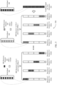
- FIG. 3 illustrates an example of downlink PRS configurations 300, 301, and 302 that support aspects of the present disclosure.
- the downlink PRS configurations 300 may implement aspects of wireless communication system 100.
- a base station 105 may transmit a downlink PRS to a UE 115.
- the UE 115 may monitor for and measure the downlink PRS.
- multiple base stations 105 may transmit a downlink PRS to the UE 115, and the UE 115 may take measurements for each of the multiple downlink PRS.
- An RSTD measurement may be an example of a measurement the UE 115 takes for the downlink PRS.
- the UE 115 or the network, or both, may perform an RTT or a TDOA estimate based on the RSTD measurements.
- the UE 115 may perform a positioning estimate based on the measurements of the downlink PRS. For example, the UE 115 may perform positioning estimation without feedback back RSTD measurements to the network. This may be an example of a UE-based mode for positioning estimation. In some other examples, the UE 115 may provide RSTD measurements for the downlink PRS to the network, and the network may perform the positioning estimating using the RSTD measurements. This may be an example of a UE-assisted mode for positioning estimation.
- a downlink PRS may be, for example, a synchronization signal block (SSB), a channel state information reference signal (CSI-RS), a tracking reference signal (TRS), or another type of signal for the downlink PRS.
- SSB synchronization signal block
- CSI-RS channel state information reference signal
- TRS tracking reference signal
- the downlink PRS configurations 300, 301, and 302 describe some of multiple different possible configurations for a downlink PRS.
- Each of the downlink PRS configurations may show, for example, a resource block which includes multiple resource elements.
- a resource element may span the time-frequency resources of one subcarrier 310 by one symbol period 315. The size of the subcarrier 310 and the symbol period 315 may be based on the configured subcarrier spacing. In some cases, a resource block may span one slot by a configurable number of subcarriers (e.g., 12 subcarriers).
- a downlink PRS may be transmitted in a downlink PRS resource element 305. The distribution of the downlink PRS resource elements 305 in the time-frequency resources may be configurable.
- the downlink PRS may, in some cases, have uniform density in the frequency domain.
- the downlink PRS configuration 300 may show a frequency comb of 1.
- the PRS configuration 301 may show a frequency comb of 4, and the PRS configuration 302 may show a frequency comb of 6.
- frequency domain staggering may be implemented.
- the PRS configurations 301 and 302 may implement frequency domain staggering.
- QPSK Quadrature Phase Shift Keying
- PN Pseudorandom Noise
- multiple ports may be configured.
- a downlink PRS configuration may use two ports for PRS transmission.
- the downlink PRS bandwidth may be configurable.
- the PRS bandwidth may be based on bandwidth or bandwidth flexibility of CSI-RS.
- the downlink PRs configurations may support configurable PRS time-domain occasions (e.g., based on CSI-RS flexibility).
- PRS transmission may be configured to be Periodic, Semi-persistent, or aperiodic. In some cases, this scheme may be configurable.
- the PRS transmission may be configured to be periodic.
- a base station 105 may transmit a MAC CE to configure the UE 115 to monitor for semi-persistent downlink PRS transmissions. The base station 105 may later transmit another MAC CE to switch the PRS transmission back to periodic or to aperiodic.
- the downlink PRS occasions may be configured by RRC signaling or by downlink control information.
- a DL PRS transmitted by a serving or neighboring cell can be configured one of two options.
- the start and end resource blocks of frequency domain allocation may be defined with respect to the common reference point A.
- the scrambling sequence for option 1 may be with respect to reference point A.
- Subcarrier spacing for option 1 may be different than that the active BWP.
- the start and end resource blocks of frequency domain allocation may be defined with respect to the start of the component carrier (CC).
- the scrambling sequence may still be with respect to reference point A.
- the subcarrier spacing cannot be different than that of an active BWP.
- a UE may perform positioning measurements from the same gNBs or different gNBs using DL PRS where at least one is configured according to Option 1 and at least one according to Option 2.
- FIG. 4 illustrates an example of an uplink PRS configuration 400 that supports aspects of the present disclosure.
- the uplink PRS configuration 400 may implement aspects of wireless communication system 100.
- a UE 115 may be configured to transmit an uplink PRS to a base station 105.
- the base station 105 may monitor for and measure the uplink PRS.
- the UE 115 may transmit an uplink PRS to multiple base stations 105, and each base station 105 may take a measurement for one of the multiple uplink PRS.
- An RSTD measurement may be an example of a measurement the base station 105 takes for the uplink PRS.
- the base station 105 or the network, or both, may perform an RTT or a TDOA estimate based on the RSTD measurements.
- a first base station 105 may transmit a first measurement report for the uplink PRS and an indicator of the location of the base station 105 to the UE 115.
- the first base station 105 may also provide at least a second measurement report generated by at least a second base station 105 and the location of at least the second base station 105 to the UE 115.
- the UE 115 may perform a positioning estimate based on the first and second measurement report and the locations of the first and second base station.
- the UE 115 may include other additional information, such as locations of additional base stations 105 and measurement reports generated by the additional base stations 105, in the positioning estimate.
- the UE 115 may apply UE-based techniques, UE-assisted techniques, or both, for an uplink PRS-based positioning estimate.
- An uplink PRS may be, for example, an SRS (e.g., a modified NR SRS), a PRACH signal, or a DMRS of PUSCH.
- the uplink PRS configurations 400 and 401 describe some of multiple different possible configurations for an uplink PRS.
- Each of the uplink PRS configurations may show, for example, a set of time-frequency resources which include multiple resource elements.
- the set of time-frequency resources may be, for example, one or more symbol periods 425 spanning a set of subcarriers 420 (e.g., as shown in uplink PRS configuration 400), or a full resource block (e.g., as may be shown in uplink PRS configuration 401).
- a resource element may span the time-frequency resources of one subcarrier 420 by one symbol period 425.
- the size of the subcarrier 420 and the symbol period 425 may be based on the configured subcarrier spacing.
- An uplink PRS may be transmitted in an uplink PRS resource element 405.
- the distribution of the downlink PRS resource elements 405 in the time-frequency resources may be configurable.
- the uplink PRS configuration 400 may be an example of non-contiguous uplink PRS transmission.
- the uplink PRS resource 410-a may correspond to a first slot and be transmitted in a first symbol period.
- the first symbol period may actually be a tenth symbol period of a slot.
- an uplink PRS transmitted in the uplink PRS resources 410 may be an example of an SRS, where the SRS is configured to be transmitted in one of a last few symbol periods of a slot.
- the uplink PRS resource 410-b may correspond to a second slot and be transmitted in a second symbol period.
- the second slot may be the same as the first slot (e.g., the uplink PRS resource 410-a and the uplink PRS resource 410-b are in the same slot). In some other example, the first slot and the second slot may be different slots.
- a UE 115 may transmit a set of uplink PRS in each of the shown uplink PRS resources 410.
- a base station 105 receiving the set of uplink PRS for each of the uplink PRS resources 410 and generate a combined signal 415. Based on the combined signal 415, the base station 105 may reconstruct the frequency domain for corresponding to the uplink PRS transmissions. For example, the base station 105 may reconstruct the frequency domain for a resource block bandwidth corresponding to the uplink PRS resources 410. The base station 105 may then perform a TOA estimate based on the combined signal 415.
- the sequence for an uplink PRS may be based on a Zadoff-Chu sequence.
- an uplink PRS may be transmitted using multiple ports (e.g., antenna ports).
- the uplink PRS may have a configurable symbol location and bandwidth. In some cases, frequency domain hopping may be applied.
- the uplink PRS transmission may be configured to be Periodic, Semi-persistent, or aperiodic, for example similar to the downlink PRS transmission.
- an SRS may be transmitted in an uplink PRS resource element 405 in one of the last symbol periods 425 of a slot (e.g., in one of the last four symbol periods 425 of the slot).
- the uplink PRS resource elements 405 may be staggered.
- the uplink PRS resource elements 405 may enable a receiving base station 105 to reconstruct the entire frequency domain of the corresponding set of subcarriers 420.
- a PRS resource for a UE 115 to transmit an uplink PRS toward a serving or neighboring cell may be configured with beginning and end in the frequency domain.
- the beginning and end of the frequency domain may be configured with respect to common reference point A.
- the start and end of the frequency domain may be configured with respect to the BWP start.
- a UE 115 may perform transmissions associated with positioning measurements towards the same gNBs or different gNBs using uplink PRS where at least one is configured according to the first example and at least one according to the second example.
- uplink PRS may be activated.
- Uplink PRS may be activated by a MAC CE message.
- the UE 115 may begin and maintain transmitting uplink PRS at some point after receiving the MAC CE.
- the UE 115 may continue transmitting uplink PRS (e.g., periodically) until another MAC CE has been received to de-activate the uplink PRS transmission.
- Uplink PRS may be activated or deactivate multiple times across the duration of a single connection.
- FIG. 5 illustrates an example of an uplink PRS configuration 500 that supports aspects of the present disclosure.
- the uplink PRS configuration 500 may implement aspects of wireless communication system 100.
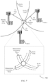
- the wireless device may use the timing differences 710 to determine the UE position 715 based on the equations described above.
- first timing difference 710-a may have measurement uncertainty 720-a
- second timing difference 710-b may have measurement uncertainty 720-b.
- a BWP implementation may contribute to power saving.
- the BWP concept may reduce a baseband processing requirement to transmit or receive narrow bandwidth.
- a BWP may enable RF-Baseband interface operation with a lower sampling rate.
- UE radio frequency bandwidth adaptation may provide UE power saving at least if the carrier bandwidth before adaptation is large.
- a common resource block 820 may indicate a resource block location in the set of common resource blocks.
- a PRB 805 may indicate a resource block within a specific carrier bandwidth part.
- a common resource block 820 may be a position in an absolute (reference) coordinate system and a physical resource block may be a position in a relative coordinate system.
- FIG. 9 illustrates an example of a PRS resource configuration 900 that supports aspects of the present disclosure.
- the PRS resource configuration 900 may implement aspects of wireless communication system 100.
- a UE 115 may be expected to measure a larger bandwidth than just the intersection of the PRS bandwidth with the active BWP. Whether such a measurement is expected by the UE may be based one of multiple different options, configurations, examples, or cases.
- the expectation may be known to the UE by gNB indication.
- the expectation may depend on whether the positioning method is UE-based or UE-assisted.
- the expectation may be known to the gNB by UE capability indication.
- the expectation may be based on whether sufficient gap before/after is provided to the UE. How much gap is considered "sufficient" is based on UE capability. Any combination of one or more of the above examples may be implemented.
- the active BWP may change during the reception of any of the above, but the UE 115 may not be expected to change the PRS measured bandwidth due to the active BWP change.
- the UE 115 may first receive a PRS which has an intersection with a first BWP (e.g., BWP1) equal to the BWP1 bandwidth. Then, the UE 115 changes to BWP2 which has a smaller bandwidth and again receives a second PRS. The UE 115 may measure the larger PRS. In some cases, the UE may have measurements gaps before/after this second PRS.
- a first BWP e.g., BWP1
- the same PRS resource may be configured in one of the component carriers with enough bandwidth to span across multiple component carriers. This may happen for the case that the PRS is defined with respect to reference point "A" as described in FIGs. 2 through 4 .
- the gNB may indicate to the UE 115 whether the same port is assumed across the whole PRS resource, or that the port in each component carrier is different.
- the UE 115 may always assume that the same set of port(s) are transmitted.
- the UE 115 may always assume that the same set of port(s) are transmitted.
- the UE 115 may always assume that the same set of port(s) are transmitted. In a fifth example, if the frequency domain separation of the 2 component carriers is smaller than a threshold, the UE 115 may always assume that the same set of port(s) are transmitted. In some cases, the UE 115 may measure the PRS bandwidth which intersects with BWP1, or with BWP2, or measure both. A UE capability may be introduced to indicate the maximum bandwidth of the PRS that the UE 115 may process for the case that the PRS configuration is allowed to span across multiple component carriers. In some cases, the time-domain gaps before/after for such a measurement may be higher than the case of a PRS measured only inside one component carrier. Any one or more of the example described herein may be implemented.
- a UE 115 may be configured with a first active BWP 915-a and a second active BWP 915-b.
- the first active BWP 915-a may be in a first component carrier 910-a
- the second active BWP 915-b may be in a second component carrier 910-b.
- the first active BWP 915-a may be an example of BWP1 as described herein
- the second active BWP 915-b may be an example of BWP2 as described herein.
- a configured PRS bandwidth 905 may span both the first component carrier 910-a and the second component carrier 910-b in bandwidth.
- the UE 115 may implement the techniques described above to transmit or receive PRS signals when the configured PRS resource (e.g., the configured PRS bandwidth 905) spans across multiple component carriers 910.
- FIG. 10 illustrates an example of a PRS resource configuration 1000 that supports aspects of the present disclosure.
- the PRS resource configuration 1000 may implement aspects of wireless communication system 100.
- a transmission reception point such as a base station 105, may configure a PRS resource for a UE 115
- the PRS resource (e.g., a configured PRS bandwidth 1005) may span across multiple active BWPs 1015, including a first active BWP 1015-a, a second active BWP 1015-b, and a third active BWP 1015-c.
- the PRS resource may be configured in a component carrier, such as component carrier 1010, with enough bandwidth to span across multiple active BWPs 1015.
- the base station 105 may indicate to the UE 115 whether the same one or more ports are assumed across the active BWPs 1015 of the component carrier 1010.
- the UE 115 may assume that the same set of one or more ports are transmitted. In a third example, if all the active BWPs 1015 are contiguous, the UE 115 may always assume that the same set of one or more ports are transmitted. In some cases, a UE capability may be used to indicate whether the UE 115 can measure PRS on multiple active BWPs 1015. The UE capability may indicate the maximum bandwidth of the PRS that the UE 115 may process for the case that the PRS configuration is supported to span across multiple BWPs 1015.
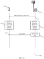
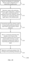
- FIG. 11 illustrates an example of a process flow 1100 that supports aspects of the present disclosure.
- process flow 1100 may implement aspects of wireless communication system 100.
- Process flow 1100 may include UE 115-b and base station 105-g, which may be respective examples of a UE 115 and a base station 105 as described herein.
- Base station 105-g may be an example of a transmission reception point as described herein.
- a network entity may control one or more transmission reception points, such as base station 105-g, to perform or facilitate one or more of the procedures described by the process flow 1100.
- base station 105-g may be an example of a serving base station for UE 115.
- Base station 105-g may configure UE 115-b with one or more BWPs as described herein.
- Base station 105-g and UE 115-b may implement techniques for determining positioning of UE 115-b.
- Process flow 1100 may show an example of a configuration for and transmission of an uplink PRS.
- a network entity may transmit an indication of a PRS configuration for base station 105-g.
- Base station 105-g may receive the indication of the PRS configuration from the network entity and, at 1105, base station 105-g may transmit the indication of the PRS configuration for base station 105-g to UE 115-b.
- UE 115-b and base station 105-g may each determine, based on the PRS configuration, a reference point within a carrier bandwidth of a component carrier.
- UE 115-b and base station 105-g may also determine a frequency domain allocation for a PRS relative to the reference point.
- the frequency domain allocation for the PRS may be, for example, a defined bandwidth, a bandwidth which spans up to a bandwidth of a carrier, a BWP, a configured number of resource blocks, a configured bandwidth corresponding to a BWP, etc.
- the reference point may differ from a starting resource block of the carrier bandwidth. In some other examples, the reference point may be a starting resource block of the carrier bandwidth.
- base station 105-g may monitor for a transmission of the PRS from UE 115-b within the frequency domain allocation.
- UE 115-b may transmit the PRS based on the frequency domain allocation.
- UE 115-b may transmit a PRS to each of multiple base stations 105. For example, UE 115-b may receive a second indication of a second PRS configuration for a second base station 105. UE 115-b may determine, based on the second PRS configuration, a second reference point within the carrier bandwidth of the component carrier and a second frequency domain allocation for a second PRS relative to the second reference point. UE 115-b may then transmit a second positioning signal within the second frequency domain allocation.
- FIG. 12 illustrates an example of a process flow 1200 that supports aspects of the present disclosure.
- process flow 1200 may implement aspects of wireless communication system 100.
- Process flow 1200 may include UE 115-c and base station 105-h, which may be respective examples of a UE 115 and a base station 105 as described herein.
- Base station 105-h may be an example of a transmission reception point as described herein.
- a network entity may control one or more transmission reception points, such as base station 105-h, to perform or facilitate one or more of the procedures described by the process flow 1200.
- base station 105-h may be an example of a serving base station for UE 115.
- Base station 105-h may configure UE 115-c with one or more BWPs as described herein.
- Base station 105-h and UE 115-c may implement techniques for determining positioning of UE 115-c.
- Process flow 1200 may show an example of a configuration for and transmission of a downlink PRS.
- a network entity may transmit an indication of a PRS configuration for base station 105-h.
- Base station 105-h may receive the indication of the PRS configuration from the network entity and, at 1205, base station 105-h may transmit the indication of the PRS configuration for base station 105-hto UE 115-c.
- UE 115-c and base station 105-h may each determine, based on the PRS configuration, a reference point within a carrier bandwidth of a component carrier.
- UE 115-c and base station 105-h may also determine a frequency domain allocation for a PRS relative to the reference point.
- the frequency domain allocation for the PRS may be, for example, a defined bandwidth, a bandwidth which spans up to a bandwidth of a carrier, a BWP, a configured number of resource blocks, a configured bandwidth corresponding to a BWP, etc.
- the reference point may differ from a starting resource block of the carrier bandwidth. In some other examples, the reference point may be a starting resource block of the carrier bandwidth.
- UE 115-c may monitor for a transmission of the PRS from base station 105-c within the frequency domain allocation.
- Base station 105-h may transmit the PRS based on the frequency domain allocation.
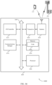
- FIG. 13 shows a block diagram 1300 of a device 1305 that supports aspects of the present disclosure.
- the device 1305 may be an example of aspects of a UE 115 as described herein.
- the device 1305 may include a receiver 1310, a communications manager 1315, and a transmitter 1320.
- the device 1305 may also include a processor. Each of these components may be in communication with one another (e.g., via one or more buses).
- the receiver 1310 may receive information such as packets, user data, or control information associated with various information channels (e.g., control channels, data channels, and information related to bandwidth part considerations for uplink and downlink positioning reference signals, etc.). Information may be passed on to other components of the device 1305.
- the receiver 1310 may be an example of aspects of the transceiver 1620 described with reference to FIG. 16 .
- the receiver 1310 may utilize a single antenna or a set of antennas.
- the communications manager 1315 may receive an indication of a positioning reference signal configuration for a transmission reception point, determine, based on the positioning reference signal configuration, a reference point within a carrier bandwidth of a component carrier and a frequency domain allocation for a positioning reference signal relative to the reference point, and transmit the positioning reference signal or measuring the positioning reference signal based on the frequency domain allocation.
- the communications manager 1315 may be an example of aspects of the communications manager 1610 described herein.
- the communications manager 1315 may be implemented in hardware, code (e.g., software or firmware) executed by a processor, or any combination thereof. If implemented in code executed by a processor, the functions of the communications manager 1315, or its sub-components may be executed by a general-purpose processor, a DSP, an application-specific integrated circuit (ASIC), a FPGA or other programmable logic device, discrete gate or transistor logic, discrete hardware components, or any combination thereof designed to perform the functions described in the present disclosure.
- code e.g., software or firmware
- ASIC application-specific integrated circuit
- FPGA field-programmable gate
- the communications manager 1315 may be physically located at various positions, including being distributed such that portions of functions are implemented at different physical locations by one or more physical components.
- the communications manager 1315, or its sub-components may be a separate and distinct component in accordance with various aspects of the present disclosure.
- the communications manager 1315, or its sub-components may be combined with one or more other hardware components, including but not limited to an input/output (I/O) component, a transceiver, a network server, another computing device, one or more other components described in the present disclosure, or a combination thereof in accordance with various aspects of the present disclosure.
- I/O input/output
- the transmitter 1320 may transmit signals generated by other components of the device 1305.
- the transmitter 1320 may be collocated with a receiver 1310 in a transceiver module.
- the transmitter 1320 may be an example of aspects of the transceiver 1620 described with reference to FIG. 16 .
- the transmitter 1320 may utilize a single antenna or a set of antennas.
- the receiver 1410 may receive information such as packets, user data, or control information associated with various information channels (e.g., control channels, data channels, and information related to bandwidth part considerations for uplink and downlink positioning reference signals, etc.). Information may be passed on to other components of the device 1405.
- the receiver 1410 may be an example of aspects of the transceiver 1620 described with reference to FIG. 16 .
- the receiver 1410 may utilize a single antenna or a set of antennas.
- the measurement report component 1525 may generate a measurement of the positioning reference signal based on the frequency domain allocation. In some examples, the measurement report component 1525 may transmit the measurement to a network entity.
- the positioning estimate component 1530 may determine a positioning estimate of the UE based on measuring the positioning reference signal within the frequency domain allocation. In some cases, the positioning estimate of the UE may be relative to the transmission reception point. In some examples, the positioning estimate component 1530 may receive positioning information that indicates a first measurement and a first location of the transmission reception point and at least a second location of at least a second transmission reception point based on transmitting the positioning reference signal. In some examples, the positioning estimate component 1530 may receive a positioning reference signal measurement report that indicates a first measurement and a first location of the transmission reception point and at least a second measurement and at least a second location of at least a second transmission reception point based on transmitting the positioning reference signal. In some examples, the positioning estimate component 1530 may determine a positioning estimate of the UE based on the positioning reference signal measurement report.
- the PRS generating component 1535 may determine a scrambling sequence for the positioning reference signal based on the reference point. In some examples, the PRS generating component 1535 may scramble a first sequence with the scrambling sequence to generate a positioning reference sequence. In some examples, the PRS generating component 1535 may generate the positioning reference signal based on the positioning reference sequence.
- the PRS generating component 1535 may determine a scrambling sequence for the positioning reference signal based on a second reference point that differs from the reference point. In some examples, the PRS generating component 1535 may generate the positioning reference signal based on the positioning reference sequence.
- the BWP configuration component 1540 may receive signaling that configures the UE with at least one bandwidth part and an active bandwidth part within the at least one bandwidth part, where the frequency domain allocation intersects with a bandwidth of the active bandwidth part. In some examples, the BWP configuration component 1540 may determine that an intersection of the frequency domain allocation and the bandwidth of the active bandwidth part satisfies a threshold. In some examples, the BWP configuration component 1540 may UE is configured with the threshold.
- the BWP configuration component 1540 may receive a measurement indicator that configures the UE to measure the positioning reference signal over the bandwidth of the frequency domain allocation that exceeds the bandwidth of the active bandwidth part.
- the threshold is based on a capability of the UE, or a type of positioning method, or a configured positioning reference signal pattern, or frequency hopping pattern, or any combination thereof.
- a bandwidth of the frequency domain allocation exceeds the bandwidth of the active bandwidth part.
- the measurement indicator is based on a type of positioning method.
- the active bandwidth part does not change during at least one positioning reference signal occasion or at least one positioning reference signal occasion group.
- the active bandwidth part does not change during a set of positioning reference signal occasions or a set of positioning reference signal occasion groups within a defined time window. In some cases, the active bandwidth part does not change during a set of positioning reference signal occasions or a set of positioning reference signal occasion groups for measuring a set of positioning reference signals of a set of transmission reception points. In some cases, the frequency domain allocation of the positioning reference signal does not change when the active bandwidth part changes to a second active bandwidth part during at least one positioning reference signal occasion or at least one positioning reference signal occasion group.
- the capability indication component 1545 may transmit a capability indicator that indicates whether the UE is capable of measuring the positioning reference signal over the bandwidth of the frequency domain allocation that exceeds the bandwidth of the active bandwidth part, where the measurement indicator is based on the capability indicator. In some examples, the capability indication component 1545 may transmit a capability indicator that indicates a defined bandwidth support for the positioning reference signal that spans a set of component carriers.
- the capability indication component 1545 may receive a gap indicator that configures a time domain gap before or after a positioning reference signal occasion. In some examples, the capability indication component 1545 may transmit a capability indicator that indicates whether the UE supports measuring the positioning reference signal on a set of active bandwidth parts.
- the capability indication component 1545 may receive a measurement indicator that configures the UE to measure the positioning reference signal over at least one of the set of active bandwidth parts based on the capability indicator. In some examples, the capability indication component 1545 may transmit a capability indicator that indicates a measurement bandwidth that the UE supports for measuring the positioning reference signal. In some cases, the capability indicator indicates a gap before or after a positioning reference signal occasion.
- the port configuration component 1550 may receive a port indication that indicates a same port has been applied across the frequency domain allocation or a different port has been applied for each component carrier of a set of component carriers, where the frequency domain allocation of the positioning reference signal spans the set of component carriers. In some examples, the port configuration component 1550 may determine a same port has been applied across the frequency domain allocation based on the frequency domain allocation of the positioning reference signal spanning a set of component carriers. In some examples, the port configuration component 1550 may determine a same port has been applied across the frequency domain allocation based on the frequency domain allocation of the positioning reference signal spanning a set of contiguous component carriers.
- the port configuration component 1550 may determine a same port has been applied across the frequency domain allocation based on the frequency domain allocation of the positioning reference signal spanning a set of component carriers within a same frequency band. In some examples, the port configuration component 1550 may determine a same port has been applied across the frequency domain allocation based on the frequency domain allocation of the positioning reference signal spanning a set of component carriers and a frequency domain separation of each pair of the set of component carriers satisfying a threshold. In some examples, the port configuration component 1550 may receive a port indication that indicates a same port has been applied for each active bandwidth part of a set of active bandwidth parts of the component carrier, where the frequency domain allocation spans the set of active bandwidth parts.
- the port configuration component 1550 may receive a port indication that indicates a different port has been applied for each active bandwidth part of a set of active bandwidth parts of the component carrier, where the frequency domain allocation spans the set of active bandwidth parts. In some examples, the port configuration component 1550 may determine a same port has been applied for each active bandwidth part of a set of active bandwidth parts of the component carrier, where the frequency domain allocation spans the set of active bandwidth parts. In some examples, the port configuration component 1550 may determine a same port has been applied for each active bandwidth part of a set of contiguous active bandwidth parts of the component carrier, where the frequency domain allocation spans the set of active bandwidth parts.
- FIG. 16 shows a diagram of a system 1600 including a device 1605 that supports aspects of the present disclosure.
- the device 1605 may be an example of or include the components of device 1305, device 1405, or a UE 115 as described herein.
- the device 1605 may include components for bi-directional voice and data communications including components for transmitting and receiving communications, including a communications manager 1610, an I/O controller 1615, a transceiver 1620, an antenna 1625, memory 1630, and a processor 1640. These components may be in electronic communication via one or more buses (e.g., bus 1645).
- buses e.g., bus 1645
- the communications manager 1610 may receive an indication of a positioning reference signal configuration for a transmission reception point, determine, based on the positioning reference signal configuration, a reference point within a carrier bandwidth of a component carrier and a frequency domain allocation for a positioning reference signal relative to the reference point, and transmit the positioning reference signal or measuring the positioning reference signal based on the frequency domain allocation.
- the I/O controller 1615 may manage input and output signals for the device 1605.
- the I/O controller 1615 may also manage peripherals not integrated into the device 1605.
- the I/O controller 1615 may represent a physical connection or port to an external peripheral.
- the I/O controller 1615 may utilize an operating system such as iOS ® , ANDROID ® , MS-DOS ® , MS-WINDOWS ® , OS/2 ® , UNIX ® , LINUX ® , or another known operating system.
- the I/O controller 1615 may represent or interact with a modem, a keyboard, a mouse, a touchscreen, or a similar device.
- the I/O controller 1615 may be implemented as part of a processor.
- a user may interact with the device 1605 via the I/O controller 1615 or via hardware components controlled by the I/O controller 1615.
- the transceiver 1620 may communicate bi-directionally, via one or more antennas, wired, or wireless links as described above.
- the transceiver 1620 may represent a wireless transceiver and may communicate bi-directionally with another wireless transceiver.
- the transceiver 1620 may also include a modem to modulate the packets and provide the modulated packets to the antennas for transmission, and to demodulate packets received from the antennas.
- the wireless device may include a single antenna 1625. However, in some cases the device may have more than one antenna 1625, which may be capable of concurrently transmitting or receiving multiple wireless transmissions.
- the memory 1630 may include RAM and ROM.
- the memory 1630 may store computer-readable, computer-executable code 1635 including instructions that, when executed, cause the processor to perform various functions described herein.
- the memory 1630 may contain, among other things, a BIOS which may control basic hardware or software operation such as the interaction with peripheral components or devices.
- the processor 1640 may include an intelligent hardware device, (e.g., a general-purpose processor, a DSP, a CPU, a microcontroller, an ASIC, an FPGA, a programmable logic device, a discrete gate or transistor logic component, a discrete hardware component, or any combination thereof).
- the processor 1640 may be configured to operate a memory array using a memory controller.
- a memory controller may be integrated into the processor 1640.
- the processor 1640 may be configured to execute computer-readable instructions stored in a memory (e.g., the memory 1630) to cause the device 1605 to perform various functions (e.g., functions or tasks supporting bandwidth part considerations for uplink and downlink positioning reference signals).
- the code 1635 may include instructions to implement aspects of the present disclosure, including instructions to support wireless communications.
- the code 1635 may be stored in a non-transitory computer-readable medium such as system memory or other type of memory. In some cases, the code 1635 may not be directly executable by the processor 1640 but may cause a computer (e.g., when compiled and executed) to perform functions described herein.
- FIG. 17 shows a block diagram 1700 of a device 1705 that supports aspects of the present disclosure.
- the device 1705 may be an example of aspects of a transmission reception point, such as a base station 105 as described herein, or a network entity controlling one or more transmission reception points.
- the network entity may be a part of a core network (e.g., a core network 130 described with reference to FIG. 1 ) and may communicate with one or more transmission reception points via backhaul links.
- the device 1705 may include a receiver 1710, a communications manager 1715, and a transmitter 1720.
- the device 1705 may also include a processor. Each of these components may be in communication with one another (e.g., via one or more buses).
- the receiver 1710 may receive information such as packets, user data, or control information associated with various information channels (e.g., control channels, data channels, and information related to bandwidth part considerations for uplink and downlink positioning reference signals, etc.). Information may be passed on to other components of the device 1705.
- the receiver 1710 may be an example of aspects of the transceiver 2020 described with reference to FIG. 20 .
- the receiver 1710 may utilize a single antenna or a set of antennas.
- the communications manager 1715 may transmit an indication of a positioning reference signal configuration for the transmission reception point, determine, based on the positioning reference signal configuration, a reference point within a carrier bandwidth of a component carrier and a frequency domain allocation for a positioning reference signal relative to the reference point, and monitor for a transmission of the positioning reference signal from a UE within the frequency domain allocation.
- the communications manager 1715 may be an example of aspects of the communications manager 2010 described herein.
- the communications manager 1715 may be implemented in hardware, code (e.g., software or firmware) executed by a processor, or any combination thereof. If implemented in code executed by a processor, the functions of the communications manager 1715, or its sub-components may be executed by a general-purpose processor, a DSP, an application-specific integrated circuit (ASIC), a FPGA or other programmable logic device, discrete gate or transistor logic, discrete hardware components, or any combination thereof designed to perform the functions described in the present disclosure.
- code e.g., software or firmware
- ASIC application-specific integrated circuit
- FPGA field-programmable gate
- the communications manager 1715 may be physically located at various positions, including being distributed such that portions of functions are implemented at different physical locations by one or more physical components.
- the communications manager 1715, or its sub-components may be a separate and distinct component in accordance with various aspects of the present disclosure.
- the communications manager 1715, or its sub-components may be combined with one or more other hardware components, including but not limited to an input/output (I/O) component, a transceiver, a network server, another computing device, one or more other components described in the present disclosure, or a combination thereof in accordance with various aspects of the present disclosure.
- I/O input/output
- the transmitter 1720 may transmit signals generated by other components of the device 1705.
- the transmitter 1720 may be collocated with a receiver 1710 in a transceiver module.
- the transmitter 1720 may be an example of aspects of the transceiver 2020 described with reference to FIG. 20 .
- the transmitter 1720 may utilize a single antenna or a set of antennas.
- FIG. 18 shows a block diagram 1800 of a device 1805 that supports aspects of the present disclosure.
- the device 1805 may be an example of aspects of a device 1705, a transmission reception point, such as a base station 105 as described herein, or a network entity controlling one or more transmission reception points.
- the network entity may be a part of a core network (e.g., a core network 130 described with reference to FIG. 1 ) and may communicate with one or more transmission reception points via backhaul links.
- the device 1805 may include a receiver 1810, a communications manager 1815, and a transmitter 1835.
- the device 1805 may also include a processor. Each of these components may be in communication with one another (e.g., via one or more buses).
- the receiver 1810 may receive information such as packets, user data, or control information associated with various information channels (e.g., control channels, data channels, and information related to bandwidth part considerations for uplink and downlink positioning reference signals, etc.). Information may be passed on to other components of the device 1805.
- the receiver 1810 may be an example of aspects of the transceiver 2020 described with reference to FIG. 20 .
- the receiver 1810 may utilize a single antenna or a set of antennas.
- the communications manager 1815 may be an example of aspects of the communications manager 1715 as described herein.
- the communications manager 1815 may include a PRS configuration indicating component 1820, a reference point determining component 1825, and a PRS monitoring component 1830.
- the communications manager 1815 may be an example of aspects of the communications manager 2010 described herein.
- the PRS configuration indicating component 1820 may transmit an indication of a positioning reference signal configuration for the transmission reception point.
- the reference point determining component 1825 may determine, based on the positioning reference signal configuration, a reference point within a carrier bandwidth of a component carrier and a frequency domain allocation for a positioning reference signal relative to the reference point.
- the PRS monitoring component 1830 may monitor for a transmission of the positioning reference signal from a UE within the frequency domain allocation.
- the transmitter 1835 may transmit signals generated by other components of the device 1805.
- the transmitter 1835 may be collocated with a receiver 1810 in a transceiver module.
- the transmitter 1835 may be an example of aspects of the transceiver 2020 described with reference to FIG. 20 .
- the transmitter 1835 may utilize a single antenna or a set of antennas.
- FIG. 19 shows a block diagram 1900 of a communications manager 1905 that supports aspects of the present disclosure.
- the communications manager 1905 may be an example of aspects of a communications manager 1715, a communications manager 1815, or a communications manager 2010 described herein.
- the communications manager 1905 may be included in a device such as a transmission reception point, a base station 105, or a network entity controlling one or more transmission reception points.
- the network entity may be a part of a core network (e.g., a core network 130 described with reference to FIG. 1 ) and may communicate with one or more transmission reception points via backhaul links.
- the communications manager 1905 may include a PRS configuration indicating component 1910, a reference point determining component 1915, a PRS monitoring component 1920, a position estimate component 1925, a measurement report component 1930, a PRS decoding component 1935, a BWP configuration component 1940, a capability indication component 1945, and a port configuration component 1950. Each of these modules may communicate, directly or indirectly, with one another (e.g., via one or more buses).
- the PRS configuration indicating component 1910 may transmit an indication of a positioning reference signal configuration for the transmission reception point.
- the PRS configuration indicating component 1910 may transmit a message instructing the UE to transmit the positioning reference signal. In some examples, the PRS configuration indicating component 1910 may transmit a gap indicator that indicates one or more symbols before or after a positioning reference signal occasion. In some cases, the message is a RRC message, a higher layer protocol message, a positioning message, an LTE positioning protocol message, a NR positioning message, DCI, or a MAC CE.
- the port configuration component 1950 may apply a same port for each active bandwidth part of a set of active bandwidth parts of the component carrier to transmit the positioning reference signal, where the frequency domain allocation spans the set of active bandwidth parts. In some examples, the port configuration component 1950 may apply a same port for each active bandwidth part of a set of contiguous active bandwidth parts of the component carrier to transmit the positioning reference signal, where the frequency domain allocation spans the set of active bandwidth parts.
- FIG. 20 shows a diagram of a system 2000 including a device 2005 that supports aspects of the present disclosure.
- the device 2005 may be an example of or include the components of device 1705, device 1805, or a base station 105 as described herein.
- the device 2005 may include components for bi-directional voice and data communications including components for transmitting and receiving communications, including a communications manager 2010, a network communications manager 2015, a transceiver 2020, an antenna 2025, memory 2030, a processor 2040, and an inter-station communications manager 2045. These components may be in electronic communication via one or more buses (e.g., bus 2050).
- buses e.g., bus 2050
- the transceiver 2020 may communicate bi-directionally, via one or more antennas, wired, or wireless links as described above.
- the transceiver 2020 may represent a wireless transceiver and may communicate bi-directionally with another wireless transceiver.
- the transceiver 2020 may also include a modem to modulate the packets and provide the modulated packets to the antennas for transmission, and to demodulate packets received from the antennas.
- the wireless device may include a single antenna 2025. However, in some cases the device may have more than one antenna 2025, which may be capable of concurrently transmitting or receiving multiple wireless transmissions.
- the memory 2030 may include RAM, ROM, or a combination thereof.
- the memory 2030 may store computer-readable code 2035 including instructions that, when executed by a processor (e.g., the processor 2040) cause the device to perform various functions described herein.
- a processor e.g., the processor 2040
- the memory 2030 may contain, among other things, a BIOS which may control basic hardware or software operation such as the interaction with peripheral components or devices.
- the inter-station communications manager 2045 may manage communications with other base station 105, and may include a controller or scheduler for controlling communications with UEs 115 in cooperation with other base stations 105. For example, the inter-station communications manager 2045 may coordinate scheduling for transmissions to UEs 115 for various interference mitigation techniques such as beamforming or joint transmission. In some examples, the inter-station communications manager 2045 may provide an X2 interface within an LTE/LTE-A wireless communication network technology to provide communication between base stations 105.
- the code 2035 may include instructions to implement aspects of the present disclosure, including instructions to support wireless communications.
- the code 2035 may be stored in a non-transitory computer-readable medium such as system memory or other type of memory. In some cases, the code 2035 may not be directly executable by the processor 2040 but may cause a computer (e.g., when compiled and executed) to perform functions described herein.
- FIG. 21 shows a flowchart illustrating a method 2100 that supports aspects of the present disclosure.
- the operations of method 2100 may be implemented by a UE 115 or its components as described herein.
- the operations of method 2100 may be performed by a communications manager as described with reference to FIGs. 13 through 16 .
- a UE may execute a set of instructions to control the functional elements of the UE to perform the functions described below. Additionally or alternatively, a UE may perform aspects of the functions described below using special-purpose hardware.
- the UE may determine, based on the positioning reference signal configuration, a reference point within a carrier bandwidth of a component carrier and a frequency domain allocation for a positioning reference signal relative to the reference point.
- the operations of 2110 may be performed according to the methods described herein. In some examples, aspects of the operations of 2110 may be performed by a reference point component as described with reference to FIGs. 13 through 16 .
- the UE may transmit the positioning reference signal or measuring the positioning reference signal based on the frequency domain allocation.
- the operations of 2115 may be performed according to the methods described herein. In some examples, aspects of the operations of 2115 may be performed by a PRS transceiver component as described with reference to FIGs. 13 through 16 .
- FIG. 22 shows a flowchart illustrating a method 2200 that supports aspects of the present disclosure.
- the operations of method 2200 may be implemented by a UE 115 or its components as described herein.
- the operations of method 2200 may be performed by a communications manager as described with reference to FIGs. 13 through 16 .
- a UE may execute a set of instructions to control the functional elements of the UE to perform the functions described below. Additionally or alternatively, a UE may perform aspects of the functions described below using special-purpose hardware.
- the UE may receive an indication of a positioning reference signal configuration for a transmission reception point.
- the operations of 2205 may be performed according to the methods described herein. In some examples, aspects of the operations of 2205 may be performed by a PRS configuration component as described with reference to FIGs. 13 through 16 .
- the UE may determine, based on the positioning reference signal configuration, a reference point within a carrier bandwidth of a component carrier and a frequency domain allocation for a positioning reference signal relative to the reference point.
- the operations of 2210 may be performed according to the methods described herein. In some examples, aspects of the operations of 2210 may be performed by a reference point component as described with reference to FIGs. 13 through 16 .
- the UE may transmit the positioning reference signal or measuring the positioning reference signal based on the frequency domain allocation.
- the operations of 2215 may be performed according to the methods described herein. In some examples, aspects of the operations of 2215 may be performed by a PRS transceiver component as described with reference to FIGs. 13 through 16 .
- the UE may generate a measurement of the positioning reference signal based on the frequency domain allocation.
- the operations of 2220 may be performed according to the methods described herein. In some examples, aspects of the operations of 2220 may be performed by a measurement report component as described with reference to FIGs. 13 through 16 .
- the UE may transmit the measurement to a network entity.
- the operations of 2225 may be performed according to the methods described herein. In some examples, aspects of the operations of 2225 may be performed by a measurement report component as described with reference to FIGs. 13 through 16 .
- FIG. 23 shows a flowchart illustrating a method 2300 that supports aspects of the present disclosure.
- the operations of method 2300 may be implemented by a UE 115 or its components as described herein.
- the operations of method 2300 may be performed by a communications manager as described with reference to FIGs. 13 through 16 .
- a UE may execute a set of instructions to control the functional elements of the UE to perform the functions described below. Additionally or alternatively, a UE may perform aspects of the functions described below using special-purpose hardware.
- the UE may receive an indication of a positioning reference signal configuration for a transmission reception point.
- the operations of 2305 may be performed according to the methods described herein. In some examples, aspects of the operations of 2305 may be performed by a PRS configuration component as described with reference to FIGs. 13 through 16 .
- the UE may determine, based on the positioning reference signal configuration, a reference point within a carrier bandwidth of a component carrier and a frequency domain allocation for a positioning reference signal relative to the reference point.
- the operations of 2310 may be performed according to the methods described herein. In some examples, aspects of the operations of 2310 may be performed by a reference point component as described with reference to FIGs. 13 through 16 .
- the UE may transmit the positioning reference signal or measuring the positioning reference signal based on the frequency domain allocation.
- the operations of 2315 may be performed according to the methods described herein. In some examples, aspects of the operations of 2315 may be performed by a PRS transceiver component as described with reference to FIGs. 13 through 16 .
- the UE may receive a positioning reference signal measurement report that indicates a first measurement and a first location of the transmission reception point and at least a second measurement and at least a second location of at least a second transmission reception point based on transmitting the positioning reference signal.
- the operations of 2320 may be performed according to the methods described herein. In some examples, aspects of the operations of 2320 may be performed by a positioning estimate component as described with reference to FIGs. 13 through 16 .
- the UE may determine a positioning estimate of the UE based on the positioning reference signal measurement report.
- the operations of 2325 may be performed according to the methods described herein. In some examples, aspects of the operations of 2325 may be performed by a positioning estimate component as described with reference to FIGs. 13 through 16 .
- FIG. 24 shows a flowchart illustrating a method 2400 that supports aspects of the present disclosure.
- the operations of method 2400 may be implemented by a base station 105 or its components as described herein.
- the operations of method 2400 may be performed by a communications manager as described with reference to FIGs. 17 through 20 .
- a base station may execute a set of instructions to control the functional elements of the base station to perform the functions described below. Additionally or alternatively, a base station may perform aspects of the functions described below using special-purpose hardware.
- some operations of the method 2400 may be performed by a transmission reception point, such as a base station 105.
- the network entity may instruct which of the operations the transmission reception point is to perform. For example, the network entity may perform some of these operations via one or more transmission reception points.
- a network entity may transmit an indication of a positioning reference signal configuration for the transmission reception point.
- the operations of 2405 may be performed according to the methods described herein. In some examples, aspects of the operations of 2405 may be performed by a PRS configuration indicating component as described with reference to FIGs. 17 through 20 .
- the network entity may determine, based on the positioning reference signal configuration, a reference point within a carrier bandwidth of a component carrier and a frequency domain allocation for a positioning reference signal relative to the reference point.
- the operations of 2410 may be performed according to the methods described herein. In some examples, aspects of the operations of 2410 may be performed by a reference point determining component as described with reference to FIGs. 17 through 20 .
- the network entity may monitor for a transmission of the positioning reference signal from a UE within the frequency domain allocation.
- the operations of 2415 may be performed according to the methods described herein. In some examples, aspects of the operations of 2415 may be performed by a PRS monitoring component as described with reference to FIGs. 17 through 20 .
- FIG. 25 shows a flowchart illustrating a method 2500 that supports aspects of the present disclosure.
- the operations of method 2500 may be implemented by a base station 105 or its components as described herein.
- the operations of method 2500 may be performed by a communications manager as described with reference to FIGs. 17 through 20 .
- a base station may execute a set of instructions to control the functional elements of the base station to perform the functions described below. Additionally or alternatively, a base station may perform aspects of the functions described below using special-purpose hardware.
- some operations of the method 2500 may be performed by a transmission reception point, such as a base station 105.
- the network entity may instruct which of the operations the transmission reception point is to perform. For example, the network entity may perform some of these operations via one or more transmission reception points.
- a network entity may transmit an indication of a positioning reference signal configuration for a transmission reception point.
- the operations of 2505 may be performed according to the methods described herein. In some examples, aspects of the operations of 2505 may be performed by a PRS configuration indicating component as described with reference to FIGs. 17 through 20 .
- the network entity may determine, based on the positioning reference signal configuration, a reference point within a carrier bandwidth of a component carrier and a frequency domain allocation for a positioning reference signal relative to the reference point.
- the operations of 2510 may be performed according to the methods described herein. In some examples, aspects of the operations of 2510 may be performed by a reference point determining component as described with reference to FIGs. 17 through 20 .
- the network entity may monitor for a transmission of the positioning reference signal from a UE within the frequency domain allocation.
- the operations of 2515 may be performed according to the methods described herein. In some examples, aspects of the operations of 2515 may be performed by a PRS monitoring component as described with reference to FIGs. 17 through 20 .
- the network entity may determine a positioning estimate of the UE based on receiving the positioning reference signal from the UE within the frequency domain allocation.
- the operations of 2520 may be performed according to the methods described herein. In some examples, aspects of the operations of 2520 may be performed by a position estimate component as described with reference to FIGs. 17 through 20 .
- a base station may execute a set of instructions to control the functional elements of the base station to perform the functions described below. Additionally or alternatively, a base station may perform aspects of the functions described below using special-purpose hardware.
- some operations of the method 2600 may be performed by a transmission reception point, such as a base station 105.
- the network entity may instruct which of the operations the transmission reception point is to perform. For example, the network entity may perform some of these operations via one or more transmission reception points.
- the network entity may determine, based on the positioning reference signal configuration, a reference point within a carrier bandwidth of a component carrier and a frequency domain allocation for a positioning reference signal relative to the reference point.
- the operations of 2610 may be performed according to the methods described herein. In some examples, aspects of the operations of 2610 may be performed by a reference point determining component as described with reference to FIGs. 17 through 20 .
- the network entity may monitor for a transmission of the positioning reference signal from a UE within the frequency domain allocation.
- the operations of 2615 may be performed according to the methods described herein. In some examples, aspects of the operations of 2615 may be performed by a PRS monitoring component as described with reference to FIGs. 17 through 20 .
- the network entity may transmit a positioning reference signal measurement report that indicates a first measurement and a first location of the transmission reception point and at least a second measurement and at least a second location of at least a second transmission reception point.
- the operations of 2620 may be performed according to the methods described herein. In some examples, aspects of the operations of 2620 may be performed by a measurement report component as described with reference to FIGs. 17 through 20 .
- CDMA code division multiple access
- TDMA time division multiple access
- FDMA frequency division multiple access
- OFDMA orthogonal frequency division multiple access
- SC-FDMA single carrier frequency division multiple access
- a CDMA system may implement a radio technology such as CDMA2000, Universal Terrestrial Radio Access (UTRA), etc.
- CDMA2000 covers IS-2000, IS-95, and IS-856 standards.
- IS-2000 Releases may be commonly referred to as CDMA2000 1X, 1X, etc.
- IS-856 TIA-856) is commonly referred to as CDMA2000 1xEV-DO, High Rate Packet Data (HRPD), etc.
- UTRA includes Wideband CDMA (WCDMA) and other variants of CDMA.
- a TDMA system may implement a radio technology such as Global System for Mobile Communications (GSM).
- GSM Global System for Mobile Communications
- An OFDMA system may implement a radio technology such as Ultra Mobile Broadband (UMB), Evolved UTRA (E-UTRA), Institute of Electrical and Electronics Engineers (IEEE) 802.11 (Wi-Fi), IEEE 802.16 (WiMAX), IEEE 802.20, Flash-OFDM, etc.
- UMB Ultra Mobile Broadband
- E-UTRA Evolved UTRA
- IEEE Institute of Electrical and Electronics Engineers
- Wi-Fi Wi-Fi
- WiMAX IEEE 802.16
- IEEE 802.20 Flash-OFDM
- UTRA and E-UTRA are part of Universal Mobile Telecommunications System (UMTS).
- LTE, LTE-A, and LTE-A Pro are releases of UMTS that use E-UTRA.
- UTRA, E-UTRA, UMTS, LTE, LTE-A, LTE-A Pro, NR, and GSM are described in documents from the organization named "3rd Generation Partnership Project" (3GPP).
- CDMA2000 and UMB are described in documents from an organization named "3rd Generation Partnership Project 2" (3GPP2).
- 3GPP2 3rd Generation Partnership Project 2
- the techniques described herein may be used for the systems and radio technologies mentioned herein as well as other systems and radio technologies. While aspects of an LTE, LTE-A, LTE-A Pro, or NR system may be described for purposes of example, and LTE, LTE-A, LTE-A Pro, or NR terminology may be used in much of the description, the techniques described herein are applicable beyond LTE, LTE-A, LTE-A Pro, or NR applications.
- a macro cell generally covers a relatively large geographic area (e.g., several kilometers in radius) and may allow unrestricted access by UEs with service subscriptions with the network provider.
- a small cell may be associated with a lower-powered base station, as compared with a macro cell, and a small cell may operate in the same or different (e.g., licensed, unlicensed, etc.) frequency bands as macro cells.
- Small cells may include pico cells, femto cells, and micro cells according to various examples.
- a pico cell for example, may cover a small geographic area and may allow unrestricted access by UEs with service subscriptions with the network provider.
- a femto cell may also cover a small geographic area (e.g., a home) and may provide restricted access by UEs having an association with the femto cell (e.g., UEs in a closed subscriber group (CSG), UEs for users in the home, and the like).
- An eNB for a macro cell may be referred to as a macro eNB.
- An eNB for a small cell may be referred to as a small cell eNB, a pico eNB, a femto eNB, or a home eNB.
- An eNB may support one or multiple (e.g., two, three, four, and the like) cells, and may also support communications using one or multiple component carriers.
- the wireless communications systems described herein may support synchronous or asynchronous operation.
- the base stations may have similar frame timing, and transmissions from different base stations may be approximately aligned in time.
- the base stations may have different frame timing, and transmissions from different base stations may not be aligned in time.
- the techniques described herein may be used for either synchronous or asynchronous operations.
- Information and signals described herein may be represented using any of a variety of different technologies and techniques.
- data, instructions, commands, information, signals, bits, symbols, and chips that may be referenced throughout the description may be represented by voltages, currents, electromagnetic waves, magnetic fields or particles, optical fields or particles, or any combination thereof.
- a general-purpose processor may be a microprocessor, but in the alternative, the processor may be any conventional processor, controller, microcontroller, or state machine.
- a processor may also be implemented as a combination of computing devices (e.g., a combination of a DSP and a microprocessor, multiple microprocessors, one or more microprocessors in conjunction with a DSP core, or any other such configuration).
- the functions described herein may be implemented in hardware, software executed by a processor, firmware, or any combination thereof. If implemented in software executed by a processor, the functions may be stored on or transmitted over as one or more instructions or code on a computer-readable medium. Other examples and implementations are within the scope of the disclosure and appended claims. For example, due to the nature of software, functions described herein can be implemented using software executed by a processor, hardware, firmware, hardwiring, or combinations of any of these. Features implementing functions may also be physically located at various positions, including being distributed such that portions of functions are implemented at different physical locations.
- Computer-readable media includes both non-transitory computer storage media and communication media including any medium that facilitates transfer of a computer program from one place to another.
- a non-transitory storage medium may be any available medium that can be accessed by a general purpose or special purpose computer.
- non-transitory computer-readable media may include random-access memory (RAM), read-only memory (ROM), electrically erasable programmable ROM (EEPROM), flash memory, compact disk (CD) ROM or other optical disk storage, magnetic disk storage or other magnetic storage devices, or any other non-transitory medium that can be used to carry or store desired program code means in the form of instructions or data structures and that can be accessed by a general-purpose or special-purpose computer, or a general-purpose or special-purpose processor.
- RAM random-access memory
- ROM read-only memory
- EEPROM electrically erasable programmable ROM
- CD compact disk
- magnetic disk storage or other magnetic storage devices or any other non-transitory medium that can be used to carry or store
- any connection is properly termed a computer-readable medium.
- the software is transmitted from a website, server, or other remote source using a coaxial cable, fiber optic cable, twisted pair, digital subscriber line (DSL), or wireless technologies such as infrared, radio, and microwave
- the coaxial cable, fiber optic cable, twisted pair, DSL, or wireless technologies such as infrared, radio, and microwave are included in the definition of medium.
- Disk and disc include CD, laser disc, optical disc, digital versatile disc (DVD), floppy disk and Blu-ray disc where disks usually reproduce data magnetically, while discs reproduce data optically with lasers. Combinations of the above are also included within the scope of computer-readable media.
Landscapes
- Engineering & Computer Science (AREA)
- Signal Processing (AREA)
- Computer Networks & Wireless Communication (AREA)
- Databases & Information Systems (AREA)
- Mobile Radio Communication Systems (AREA)
- Position Fixing By Use Of Radio Waves (AREA)
- Radar Systems Or Details Thereof (AREA)
Applications Claiming Priority (4)
| Application Number | Priority Date | Filing Date | Title |
|---|---|---|---|
| US201962794958P | 2019-01-21 | 2019-01-21 | |
| US201962795514P | 2019-01-22 | 2019-01-22 | |
| US16/746,594 US12273286B2 (en) | 2019-01-21 | 2020-01-17 | Bandwidth part operation and downlink or uplink positioning reference signal scheme |
| PCT/US2020/014404 WO2020154289A1 (en) | 2019-01-21 | 2020-01-21 | Bandwidth part operation and downlink or uplink positioning reference signal scheme |
Publications (3)
| Publication Number | Publication Date |
|---|---|
| EP3915308A1 EP3915308A1 (en) | 2021-12-01 |
| EP3915308B1 true EP3915308B1 (en) | 2025-07-02 |
| EP3915308C0 EP3915308C0 (en) | 2025-07-02 |
Family
ID=71609370
Family Applications (1)
| Application Number | Title | Priority Date | Filing Date |
|---|---|---|---|
| EP20705862.9A Active EP3915308B1 (en) | 2019-01-21 | 2020-01-21 | Bandwidth part operation and downlink or uplink positioning reference signal scheme |
Country Status (9)
| Country | Link |
|---|---|
| US (3) | US12273286B2 (https=) |
| EP (1) | EP3915308B1 (https=) |
| JP (2) | JP7500578B2 (https=) |
| KR (1) | KR102928923B1 (https=) |
| CN (2) | CN118509988A (https=) |
| AU (1) | AU2020211927B2 (https=) |
| BR (1) | BR112021013323A2 (https=) |
| TW (1) | TWI820290B (https=) |
| WO (1) | WO2020154289A1 (https=) |
Families Citing this family (73)
| Publication number | Priority date | Publication date | Assignee | Title |
|---|---|---|---|---|
| US10736074B2 (en) | 2017-07-31 | 2020-08-04 | Qualcomm Incorporated | Systems and methods to facilitate location determination by beamforming of a positioning reference signal |
| US12273286B2 (en) | 2019-01-21 | 2025-04-08 | Qualcomm Incorporated | Bandwidth part operation and downlink or uplink positioning reference signal scheme |
| CN114040508A (zh) * | 2019-02-02 | 2022-02-11 | 华为技术有限公司 | 通信方法和装置 |
| KR102674149B1 (ko) * | 2019-02-14 | 2024-06-13 | 애플 인크. | 새로운 무선방식(nr) 포지셔닝을 위한 다운링크(dl) 포지셔닝 기준 신호(prs) 대역폭 부분(bwp) 구성 기준 신호 설계 및 사용자 장비(ue) 기반 포지셔닝 향상들 |
| GB2583691B (en) * | 2019-02-15 | 2021-11-03 | Samsung Electronics Co Ltd | Methods, apparatus, and systems for transmitting and receiving positioning reference signals in 5G new radio networks |
| CN111277385B (zh) * | 2019-03-22 | 2021-10-22 | 维沃移动通信有限公司 | 定位参考信号配置方法、网络设备及终端 |
| CN110557235B (zh) * | 2019-03-27 | 2023-04-07 | 中兴通讯股份有限公司 | 定位参考信号的发送、接收方法、装置、收发节点 |
| US11777764B2 (en) | 2019-03-28 | 2023-10-03 | Qualcomm Incorporated | Sounding reference signal waveform design for wireless communications |
| US11239967B2 (en) | 2019-05-02 | 2022-02-01 | Qualcomm Incorporated | Patterns for reference signals used for positioning in a wireless communications system |
| WO2020222522A1 (en) | 2019-05-02 | 2020-11-05 | Samsung Electronics Co., Ltd. | Method and apparatus for measuring a position in a wireless communication network |
| US11546114B2 (en) * | 2019-05-10 | 2023-01-03 | Huawei Technologies Co., Ltd. | Sounding reference signal configuration for new radio positioning |
| US11082183B2 (en) | 2019-09-16 | 2021-08-03 | Qualcomm Incorporated | Comb shift design |
| CN114731485B (zh) * | 2019-11-30 | 2024-10-11 | 华为技术有限公司 | 一种定位信息的确定方法及通信装置 |
| JP7579865B2 (ja) * | 2020-01-29 | 2024-11-08 | クゥアルコム・インコーポレイテッド | ダウンリンク制御情報(dci)ベースのトリガ測位基準信号(prs) |
| US20230069947A1 (en) * | 2020-02-27 | 2023-03-09 | Lg Electronics Inc. | Method for transmitting and receiving signal in wireless communication system, and apparatus supporting same |
| US11582629B2 (en) * | 2020-04-03 | 2023-02-14 | Qualcomm Incorporated | Determination of an active bandwidth part transition during a positioning session |
| US12418378B2 (en) * | 2020-05-06 | 2025-09-16 | Beijing Xiaomi Mobile Software Co., Ltd. | Information transmission method and communication device, and storage medium |
| EP4193718A1 (en) * | 2020-08-06 | 2023-06-14 | Telefonaktiebolaget LM Ericsson (publ) | Configuring positioning signals and measurements to reduce latency |
| CN112075049B (zh) * | 2020-08-06 | 2023-10-03 | 北京小米移动软件有限公司 | 参考信号的配置、接收方法及装置、网络设备、用户设备及存储介质 |
| CN115004794B (zh) | 2020-08-07 | 2025-06-17 | 中兴通讯股份有限公司 | 一种用于参考信号时间同步与校准的方法 |
| US11848879B2 (en) * | 2020-08-10 | 2023-12-19 | Qualcomm Incorporated | Signaling consideration for new radio positioning with disjoint bandwidth segments |
| US11877262B2 (en) | 2020-08-13 | 2024-01-16 | Qualcomm Incorporated | Interaction of uplink and downlink positioning reference signals (PRS) with respect to discontinuous reception (DRX) |
| WO2022032599A1 (zh) * | 2020-08-13 | 2022-02-17 | Oppo广东移动通信有限公司 | 测量方法和终端设备 |
| US12301487B2 (en) * | 2020-08-28 | 2025-05-13 | Qualcomm Incorporated | Environment-aware positioning reference signal (PRS) |
| WO2022061617A1 (en) * | 2020-09-23 | 2022-03-31 | Nokia Shanghai Bell Co., Ltd. | Positioning reference signal transmission triggered by sounding reference signal |
| WO2022066391A1 (en) * | 2020-09-28 | 2022-03-31 | Qualcomm Incorporated | Multiple search windows associated with measurement of a downlink positioning reference signal |
| CN114363833B (zh) * | 2020-09-28 | 2022-09-13 | 北京紫光展锐通信技术有限公司 | 一种多播业务资源指示方法、装置及设备、存储介质 |
| EP4284097A3 (en) * | 2020-10-01 | 2024-01-24 | Apple Inc. | Using non-positioning signals for positioning in downlink and/or uplink |
| CN116324469B (zh) * | 2020-10-02 | 2026-02-03 | 高通股份有限公司 | 由ue同时处理nr中的多个定位频率层 |
| US11936419B2 (en) * | 2020-10-06 | 2024-03-19 | Qualcomm Incorporated | Determination of capability of user equipment to measure a downlink positioning reference signal across a plurality of frequency hops |
| CN114374491B (zh) * | 2020-10-15 | 2024-08-23 | 维沃移动通信有限公司 | 定位方法、终端及网络侧设备 |
| CN114374987B (zh) * | 2020-10-15 | 2024-08-13 | 维沃移动通信有限公司 | 定位方法、终端及网络侧设备 |
| WO2022077512A1 (zh) * | 2020-10-16 | 2022-04-21 | 华为技术有限公司 | 一种通信方法及装置 |
| EP4229801B1 (en) | 2020-10-16 | 2025-09-03 | Nokia Technologies Oy | User equipment positioning |
| WO2022081258A1 (en) * | 2020-10-16 | 2022-04-21 | Qualcomm Incorporated | Measurement report with measurement information of multiple positioning reference signal measurement occasions associated with a transmission reception point |
| US12562870B2 (en) | 2020-12-03 | 2026-02-24 | Qualcomm Incorporated | Aggregation of positioning signal and supplemental signal |
| WO2022116164A1 (zh) * | 2020-12-04 | 2022-06-09 | 北京小米移动软件有限公司 | 定位方法、装置、通信设备和存储介质 |
| CN114650499B (zh) * | 2020-12-21 | 2023-09-15 | 维沃移动通信有限公司 | 定位测量方法、装置、设备及可读存储介质 |
| WO2022147805A1 (zh) * | 2021-01-08 | 2022-07-14 | Oppo广东移动通信有限公司 | 定位测量的方法、终端设备及网络设备 |
| CN115119535B (zh) * | 2021-01-22 | 2025-12-05 | 北京小米移动软件有限公司 | 定位测量信息确定方法和装置、同步误差发送方法和装置 |
| US11991662B2 (en) * | 2021-01-28 | 2024-05-21 | Qualcomm Incorporated | Positioning reference signal adaptation in distributed ranging system |
| CN115190415B (zh) * | 2021-04-02 | 2025-07-11 | 华为技术有限公司 | 一种通信方法、装置及系统 |
| CN117158068A (zh) | 2021-04-07 | 2023-12-01 | 高通股份有限公司 | 用户装备(ue)定位中的定位参考信号(prs)保护 |
| WO2023275044A1 (en) * | 2021-06-30 | 2023-01-05 | Fraunhofer-Gesellschaft zur Förderung der angewandten Forschung e.V. | Positioning for user equipments with limited capabilities |
| CN121310261A (zh) | 2021-07-23 | 2026-01-09 | 欧芬诺有限责任公司 | 用于寻呼消息接收的无线设备和基站 |
| US12526604B2 (en) * | 2021-09-02 | 2026-01-13 | Apple Inc. | Positioning capabilities of reduced capability new radio devices |
| WO2023046371A1 (en) * | 2021-09-21 | 2023-03-30 | Sony Group Corporation | Method for facilitating reference signal communication in a wireless system |
| US11943156B2 (en) * | 2021-09-24 | 2024-03-26 | Qualcomm Incorporated | Processing positioning reference signals according to priority |
| US20250119861A1 (en) * | 2021-09-27 | 2025-04-10 | Qualcomm Incorporated | Minimize user equipment requested positioning reference signal measurement gaps for positioning |
| US20240388402A1 (en) * | 2021-09-28 | 2024-11-21 | Beijing Xiaomi Mobile Software Co., Ltd. | Resource configuration method and apparatus, device, and storage medium |
| US11985644B2 (en) * | 2021-09-30 | 2024-05-14 | Qualcomm Incorporated | Measurement behavior in a processing window |
| US20230147301A1 (en) * | 2021-11-11 | 2023-05-11 | Qualcomm Incorporated | Techniques for indicating measurement gaps and associating measurement gap patterns with bandwidth part hopping patterns |
| EP4436281A4 (en) * | 2021-11-18 | 2025-08-13 | Beijing Xiaomi Mobile Software Co Ltd | METHOD AND APPARATUS FOR TRANSMITTING REFERENCE SIGNAL FOR POSITIONING PURPOSE, AND STORAGE MEDIUM |
| CN116347325B (zh) * | 2021-12-24 | 2025-11-21 | 维沃移动通信有限公司 | 定位方法、设备及可读存储介质 |
| CN116418468A (zh) * | 2021-12-30 | 2023-07-11 | 维沃移动通信有限公司 | 多端口定位参考信号测量方法、装置及通信设备 |
| US20250088331A1 (en) * | 2022-01-27 | 2025-03-13 | Ntt Docomo, Inc. | Terminal, base station and communication method |
| WO2023144975A1 (ja) * | 2022-01-27 | 2023-08-03 | 株式会社Nttドコモ | 端末、基地局及び通信方法 |
| KR102930851B1 (ko) | 2022-02-03 | 2026-02-25 | 한국전자통신연구원 | 다양한 QoS를 지원하는 기지국 간 주파수 공유 방법 및 장치 |
| US12519585B2 (en) | 2022-04-01 | 2026-01-06 | Qualcomm Incorporated | Comb offset hopping for sounding reference signal transmissions |
| JP2025515348A (ja) * | 2022-04-28 | 2025-05-14 | エルジー エレクトロニクス インコーポレイティド | 無線通信システムにおいて端末が測位のための測定を行う方法及びそのための装置 |
| KR20250012562A (ko) * | 2022-05-24 | 2025-01-24 | 퀄컴 인코포레이티드 | 어그리게이팅된 업링크 포지셔닝 신호 구성 |
| US12506511B2 (en) * | 2022-08-05 | 2025-12-23 | Qualcomm Incorporated | Comb offset hopping for SRS |
| CN117596606A (zh) * | 2022-08-08 | 2024-02-23 | 华为技术有限公司 | 定位配置方法、装置及存储介质 |
| EP4588204A1 (en) * | 2022-09-12 | 2025-07-23 | Qualcomm Incorporated | Measuring a subset of a positioning reference signal (prs) bandwidth when the user equipment (ue) is configured with a larger prs bandwidth than the prs bandwidth the ue is capable of processing |
| CN117998401A (zh) * | 2022-11-04 | 2024-05-07 | 北京三星通信技术研究有限公司 | 一种用于定位的信号发送和/或接收的方法和装置 |
| KR20240146657A (ko) | 2023-01-17 | 2024-10-08 | 지티이 코포레이션 | 무선 통신에서의 포지셔닝 방식 |
| WO2024171462A1 (ja) * | 2023-02-17 | 2024-08-22 | 株式会社Nttドコモ | 端末、通信方法及び無線通信システム |
| CN118785185A (zh) * | 2023-04-04 | 2024-10-15 | 北京三星通信技术研究有限公司 | 一种与定位有关的方法和装置 |
| CN118784486A (zh) * | 2023-04-07 | 2024-10-15 | 中国移动通信有限公司研究院 | 通信处理方法、装置、设备及可读存储介质 |
| US20240407034A1 (en) * | 2023-05-30 | 2024-12-05 | Qualcomm Incorporated | Wireless communication methods and systems having a first instance of information on a sub-band and a second instance of the information on a different sub-band |
| US20250048329A1 (en) * | 2023-08-02 | 2025-02-06 | Qualcomm Incorporated | Expiration timer for double difference positioning correction |
| CN119946803A (zh) * | 2023-11-03 | 2025-05-06 | 华为技术有限公司 | 一种通信方法及装置 |
| WO2026071675A1 (ko) * | 2024-09-24 | 2026-04-02 | 엘지전자 주식회사 | 무선 통신 시스템에서 통신을 수행하기 위한 방법 및 장치 |
Citations (1)
| Publication number | Priority date | Publication date | Assignee | Title |
|---|---|---|---|---|
| WO2021071570A1 (en) * | 2019-10-10 | 2021-04-15 | Qualcomm Incorporated | Methods and apparatuses for per-band capability reporting and relation to band-agnostic positioning signals |
Family Cites Families (165)
| Publication number | Priority date | Publication date | Assignee | Title |
|---|---|---|---|---|
| JPH07111675A (ja) | 1993-08-19 | 1995-04-25 | Nippon Steel Corp | 移動体の位置決め方法及びその装置、並びにそれを用いた移動体通信システム |
| US7035663B1 (en) | 2001-10-30 | 2006-04-25 | Sprint Communications Company, L.P. | Wireless telecommunications overlay system |
| US7095813B2 (en) | 2002-05-16 | 2006-08-22 | Qualcomm Incorporated | System and method for the detection and compensation of radio signal time of arrival errors |
| CN1723647B (zh) | 2002-10-26 | 2010-08-25 | 韩国电子通信研究院 | 利用comb模式码元的跳频正交频分多址方法 |
| US7437164B2 (en) | 2004-06-08 | 2008-10-14 | Qualcomm Incorporated | Soft handoff for reverse link in a wireless communication system with frequency reuse |
| US9036538B2 (en) | 2005-04-19 | 2015-05-19 | Qualcomm Incorporated | Frequency hopping design for single carrier FDMA systems |
| US8589532B2 (en) | 2005-06-24 | 2013-11-19 | Qualcomm Incorporated | Apparatus and method for determining WLAN access point position |
| CN1801680A (zh) | 2005-08-23 | 2006-07-12 | 华为技术有限公司 | 基于交织频分多址的导频复用方法及其装置 |
| KR101265632B1 (ko) | 2006-12-12 | 2013-05-22 | 엘지전자 주식회사 | 참조 신호 전송, 참조 신호 전송 패턴 설정, 자원 블록설정 및 할당을 위한 방법 및 장치 |
| JP4935993B2 (ja) | 2007-02-05 | 2012-05-23 | 日本電気株式会社 | 無線通信システムにおけるリファレンス信号生成方法および装置 |
| KR101350134B1 (ko) | 2007-04-26 | 2014-01-08 | 엘지전자 주식회사 | 기준신호 전송 방법 |
| US7965689B2 (en) | 2007-05-14 | 2011-06-21 | Motorola Mobility, Inc. | Reference sequence construction for fast cell search |
| US8045628B2 (en) | 2007-10-18 | 2011-10-25 | Nokia Corporation | Digital video broadcast service discovery |
| CN101933264A (zh) | 2008-02-01 | 2010-12-29 | 夏普株式会社 | 发送机、接收机、发送方法和接收方法 |
| CN101651469B (zh) | 2008-08-15 | 2013-07-24 | 三星电子株式会社 | 用于lte系统中发送上行监测参考符号的跳频方法 |
| US20100130230A1 (en) | 2008-11-21 | 2010-05-27 | Qualcomm Incorporated | Beacon sectoring for position determination |
| EP2389026B1 (en) | 2009-01-14 | 2014-10-22 | China Academy of Telecommunications Technology | Method and system for coordinated transmission and a mobile terminal and network side device |
| KR101644881B1 (ko) | 2009-04-10 | 2016-08-03 | 엘지전자 주식회사 | 무선 이동 통신 시스템에 있어서, 사용자 기기의 위치를 결정하기 위한 방법 및 이를 수행하기 위한 장치 |
| KR101738162B1 (ko) | 2009-04-10 | 2017-05-22 | 엘지전자 주식회사 | 무선 통신 시스템에서 포지셔닝 참조 신호 전송 방법 및 장치 |
| JP5411351B2 (ja) | 2009-04-27 | 2014-02-12 | テレフオンアクチーボラゲット エル エム エリクソン(パブル) | ワイヤレス通信システムにおける方法および装置 |
| US9002354B2 (en) | 2009-06-12 | 2015-04-07 | Google Technology Holdings, LLC | Interference control, SINR optimization and signaling enhancements to improve the performance of OTDOA measurements |
| CN101616360B (zh) | 2009-07-24 | 2012-05-09 | 中兴通讯股份有限公司 | 一种定位参考信号的发送方法及系统 |
| CN101695191B (zh) | 2009-09-29 | 2014-04-09 | 中兴通讯股份有限公司 | 一种分配测量参考信号资源的系统及方法 |
| EP2343849B1 (en) | 2010-01-07 | 2019-05-29 | Samsung Electronics Co., Ltd. | Apparatus and method for enhancing features of uplink reference signals |
| US8750870B2 (en) | 2010-01-08 | 2014-06-10 | Qualcomm Incorporated | Method and apparatus for positioning of devices in a wireless network |
| US8780843B2 (en) | 2010-02-05 | 2014-07-15 | Lg Electronics Inc. | Method and apparatus for transmitting a sounding reference signal |
| US8682389B2 (en) | 2010-05-03 | 2014-03-25 | Telefonaktiebolaget Lm Ericsson (Publ) | Methods and apparatus for positioning measurement in multi-antenna transmission systems |
| KR101191215B1 (ko) | 2010-07-16 | 2012-10-15 | 엘지전자 주식회사 | 무선 통신 시스템에서 위치 결정 방법 및 장치 |
| US8812030B2 (en) | 2010-07-22 | 2014-08-19 | Qualcomm Incorporated | Sensing relative position from a wireless transceiver |
| CN103154899A (zh) | 2010-10-04 | 2013-06-12 | 京瓷株式会社 | 移动通信方法、无线终端和基站 |
| JP2012114901A (ja) | 2010-11-05 | 2012-06-14 | Sharp Corp | 移動局装置、基地局装置、方法および集積回路 |
| CN102595514B (zh) | 2011-01-12 | 2015-03-18 | 上海贝尔股份有限公司 | 非周期性探测参考信号的配置方法 |
| US9119102B2 (en) * | 2011-04-04 | 2015-08-25 | Telefonaktiebolaget Lm Ericsson (Publ) | Radio network node and method for using positioning gap indication for enhancing positioning performance |
| US8494533B2 (en) | 2011-07-28 | 2013-07-23 | Telefonaktiebolaget L M Ericsson (Publ) | Beamforming for cell edge capacity improvement in a heterogeneous network |
| KR101645827B1 (ko) | 2011-08-12 | 2016-08-04 | 인터디지탈 패튼 홀딩스, 인크 | 확장 반송파 및 반송파 세그먼트에 대한 기준 신호 구성 |
| US20170164315A1 (en) | 2011-08-18 | 2017-06-08 | Rivada Research, Llc | Method and System for Performing Trilateration for Fixed Infrastructure Nodes (FIN) Based On Enhanced Location Based Information |
| US20130165052A1 (en) | 2011-12-23 | 2013-06-27 | Yao-Lung Chuang | Method for adaptively performing radio link control within a network, and associated apparatus |
| CN103209475B (zh) | 2012-01-16 | 2016-05-25 | 华为技术有限公司 | 定位方法、定位服务器、终端和基站 |
| CN103220101B (zh) | 2012-01-19 | 2018-02-16 | 中兴通讯股份有限公司 | 频谱梳信令的通知、探测参考信号的发送方法与装置 |
| CN104081709B (zh) | 2012-01-27 | 2017-09-08 | 交互数字专利控股公司 | 用于在基于多载波和/或准校准网络中提供ePDCCH的装置和/或方法 |
| US9913239B2 (en) | 2012-03-09 | 2018-03-06 | Qualcomm Incorporated | Method and system for determining location of mobile devices in a femtocell |
| JP6073073B2 (ja) | 2012-05-10 | 2017-02-01 | シャープ株式会社 | 端末装置、基地局装置および通信方法 |
| EP3139193A1 (en) | 2012-06-05 | 2017-03-08 | NextNav, LLC | Systems and methods for location positioning of user device |
| WO2014017965A2 (en) | 2012-07-27 | 2014-01-30 | Telefonaktiebolaget L M Ericsson (Publ) | Enhancing positioning in multi-plmn deployments |
| WO2014019125A1 (zh) | 2012-07-30 | 2014-02-06 | 华为技术有限公司 | 用户设备的定位方法、数据发送方法、装置及用户设备 |
| US10845453B2 (en) * | 2012-08-03 | 2020-11-24 | Polte Corporation | Network architecture and methods for location services |
| EP2932740B1 (en) | 2012-12-12 | 2020-04-29 | PoLTE Corporation | Multi-path mitigation in rangefinding and tracking objects using reduced attenuation rf technology |
| US9651653B2 (en) | 2012-12-24 | 2017-05-16 | Qualcomm Incorporated | Positioning reference signal (PRS) generation for multiple transmit antenna systems |
| US9143291B2 (en) | 2012-12-27 | 2015-09-22 | Google Technology Holdings LLC | Method and apparatus for device-to-device communication |
| ES2927801T3 (es) | 2013-01-16 | 2022-11-11 | Interdigital Patent Holdings Inc | Eficiencia del espectro de enlace ascendente mejorada |
| CN103944685B (zh) | 2013-01-18 | 2017-10-10 | 华为技术有限公司 | 扩展参考信号的方法、设备和通信系统 |
| EP2949055A1 (en) | 2013-01-25 | 2015-12-02 | Interdigital Patent Holdings, Inc. | Methods and apparatus for vertical beamforming |
| CN104010363B (zh) | 2013-02-26 | 2018-05-29 | 华为技术有限公司 | 一种定位参考信号子帧的发送、接收方法及装置 |
| WO2014153761A1 (zh) | 2013-03-28 | 2014-10-02 | 华为技术有限公司 | 一种处理波束赋形的方法及装置 |
| JP6185748B2 (ja) | 2013-04-26 | 2017-08-23 | 株式会社Nttドコモ | 位置情報演算装置、中継装置及び通信システム |
| US9590744B2 (en) | 2013-05-06 | 2017-03-07 | Alcatel Lucent | Method and apparatus for beamforming |
| US9432809B2 (en) | 2013-07-12 | 2016-08-30 | Qualcomm Incorporated | Providing OTDOA PRS assistance data |
| EP3018927B1 (en) | 2013-08-20 | 2017-10-18 | Huawei Technologies Co., Ltd. | Communication method and device |
| US9377522B2 (en) | 2013-08-22 | 2016-06-28 | Qualcomm Incorporated | Utilizing a reference signal for indoor positioning |
| US9661603B2 (en) | 2013-08-30 | 2017-05-23 | Qualcomm Incorporated | Passive positioning utilizing beacon neighbor reports |
| US10174358B2 (en) | 2013-10-31 | 2019-01-08 | Rutgers, The State University Of New Jersey | Assay for identification of therapeutics targeting ternary complex formation in protein synthesis |
| US9755797B2 (en) | 2013-12-26 | 2017-09-05 | Mediatek Singapore Pte. Ltd. | Localization-based beamforming scheme for systems with multiple antennas |
| US9774429B2 (en) | 2014-03-12 | 2017-09-26 | Qualcomm Incorporated | Techniques for transmitting positioning reference signals in an unlicensed radio frequency spectrum band |
| JP2015185953A (ja) | 2014-03-20 | 2015-10-22 | 株式会社Nttドコモ | ビーム選択方法、基地局、およびユーザ装置 |
| US9755712B1 (en) | 2014-04-30 | 2017-09-05 | Quantenna Communications, Inc. | Composite sounding for MIMO beamforming in a wireless home network |
| WO2015199392A1 (ko) * | 2014-06-23 | 2015-12-30 | 엘지전자(주) | 무선 통신 시스템에서 포지셔닝(Positioning)을 수행하기 위한 방법 및 이를 위한 장치 |
| US10341980B2 (en) * | 2014-08-28 | 2019-07-02 | Lg Electronics Inc. | Method for receiving reference signal in wireless communication system and device for same |
| US10439775B2 (en) | 2014-09-02 | 2019-10-08 | Qualcomm Incorporated | Randomization of PRS frequency offsets and muting patterns in LTE for EOTDOA |
| RU2653495C1 (ru) | 2014-09-25 | 2018-05-10 | Телефонактиеболагет Лм Эрикссон (Пабл) | Способ и устройство для улучшенного опорного сигнала восходящей линии связи в системах listen-before-talk |
| US20160094326A1 (en) | 2014-09-26 | 2016-03-31 | Electronics And Telecommunications Research Institute | Method and apparatus for transmitting channel state information reference signal |
| US9955462B2 (en) | 2014-09-26 | 2018-04-24 | Qualcomm Incorporated | Ultra-low latency LTE control data communication |
| EP3349032A1 (en) | 2014-10-24 | 2018-07-18 | Polte Corporation | Partially synchronized multilateration or trilateration method and system for positional finding using rf |
| US20160223639A1 (en) | 2015-01-29 | 2016-08-04 | Intel Corporation | Wireless systems and methods |
| US20160226647A1 (en) | 2015-01-30 | 2016-08-04 | Nokia Solutions And Networks Oy | Reference precoding vectors for multiple rank indications for channel quality indication (cqi) reporting in a wireless |
| WO2016155810A1 (en) | 2015-03-31 | 2016-10-06 | Sony Corporation | Method and apparatus for positioning a mobile terminal in a radio network |
| CN107431678B (zh) | 2015-04-08 | 2021-07-16 | 苹果公司 | 定位参考系统(prs)增强设计 |
| EP3281347B1 (en) | 2015-04-10 | 2021-06-02 | Telefonaktiebolaget LM Ericsson (publ) | Enhanced positioning reference signal patterns for positioning |
| CN106341882A (zh) | 2015-07-17 | 2017-01-18 | 北京信威通信技术股份有限公司 | 一种lte系统的终端定位方法 |
| US9955303B2 (en) | 2015-07-21 | 2018-04-24 | IP Funding Group, LLC | Determining relative position with a BLE beacon |
| US9733337B2 (en) | 2015-08-28 | 2017-08-15 | Qualcomm Incorporated | Support of downlink positioning using coherent and non-coherent signal acquisition |
| CN106506127B (zh) | 2015-09-06 | 2021-03-16 | 中兴通讯股份有限公司 | 一种传输信息的方法和装置 |
| KR102284044B1 (ko) | 2015-09-10 | 2021-07-30 | 삼성전자주식회사 | 무선 통신 시스템에서 위치 추정 방법 및 장치 |
| EP3352404B1 (en) | 2015-09-14 | 2020-12-23 | LG Electronics Inc. | Method for correcting frequency offset in v2v communication and device for same |
| EP3171194B1 (en) | 2015-11-19 | 2021-01-13 | u-blox AG | Calculating a ranging measurement in a cellular communications network |
| US10541848B2 (en) | 2015-12-21 | 2020-01-21 | Lg Electronics Inc. | Method and apparatus for generating and transmitting reference signal and data in wireless communication system |
| EP3391555B1 (en) | 2015-12-22 | 2023-02-22 | Samsung Electronics Co., Ltd. | Scheme for configuring reference signal and communicating channel state information in a wireless communication system using multiple antenna ports |
| US11228462B2 (en) | 2016-01-19 | 2022-01-18 | Lg Electronics Inc. | Method for transmitting or receiving sounding reference signal in wireless communication system supporting unlicensed band, and device for supporting same |
| US10736113B2 (en) | 2016-02-16 | 2020-08-04 | Qualcomm Incorporated | Positioning signal techniques for narrowband devices |
| US10317509B2 (en) | 2016-03-31 | 2019-06-11 | Qualcomm Incorporated | PRS-based terrestrial beacon system (TBS) implementations |
| EP3446413B1 (en) | 2016-04-20 | 2019-10-30 | Telefonaktiebolaget LM Ericsson (publ) | Method and apparatus for improved reception of positioning reference signals |
| US10333670B2 (en) | 2016-05-06 | 2019-06-25 | Qualcomm Incorporated | Sounding reference signals with collisions in asymmetric carrier aggregation |
| US10505597B2 (en) | 2016-05-09 | 2019-12-10 | Qualcomm Incorporated | Reference signals and link adaptation for massive MIMO |
| US10716084B2 (en) | 2016-05-18 | 2020-07-14 | Qualcomm Incorporated | Narrowband positioning signal design and procedures |
| US10021667B2 (en) | 2016-06-23 | 2018-07-10 | Qualcomm Incorporated | Positioning in beamformed communications |
| US10756868B2 (en) | 2016-07-01 | 2020-08-25 | Qualcomm Incorporated | Techniques for transmitting a physical uplink shared channel in an uplink pilot time slot |
| WO2018012882A1 (en) | 2016-07-12 | 2018-01-18 | Lg Electronics Inc. | Method and apparatus for performing mini-subframe based alignment for new radio access technology in wireless communication system |
| US11122535B2 (en) | 2016-07-15 | 2021-09-14 | Qualcomm Incorporated | Techniques for locating devices using narrowband positioning reference signals |
| KR102355797B1 (ko) | 2016-08-09 | 2022-01-26 | 삼성전자 주식회사 | 무선 셀룰라 통신 시스템에서 채널 전송 방법 및 장치 |
| CN107733549B (zh) | 2016-08-10 | 2020-09-25 | 华为技术有限公司 | 信道质量信息计算方法、装置及系统 |
| WO2018028788A1 (en) | 2016-08-11 | 2018-02-15 | Sony Mobile Communications Inc. | Positioning of mobile devices |
| EP3487102A4 (en) | 2016-08-11 | 2019-07-17 | Huawei Technologies Co., Ltd. | METHOD FOR TRANSMITTING A DEMODULATION REFERENCE SIGNAL AND ASSOCIATED DEVICE |
| US10045325B2 (en) | 2016-08-12 | 2018-08-07 | Innovative Technology Lab Co., Ltd. | Method and apparatus for transmitting/receiving positioning reference signal in wireless communication system |
| CN107733563B (zh) | 2016-08-12 | 2019-08-13 | 中兴通讯股份有限公司 | 参考信号的发送方法及装置 |
| ES2767283T3 (es) * | 2016-08-12 | 2020-06-17 | Nokia Technologies Oy | Detección de posición de equipo de usuario dentro de una red de telecomunicación inalámbrica |
| US10547421B2 (en) | 2016-09-30 | 2020-01-28 | Qualcomm Incorporated | Scheduling for positioning reference signal (PRS) in narrowband-internet of things (NB-IoT) |
| US10631301B2 (en) | 2016-09-30 | 2020-04-21 | Qualcomm Incorporated | Positioning reference signal enhancements |
| EP3306337A1 (en) | 2016-10-10 | 2018-04-11 | Fraunhofer Gesellschaft zur Förderung der Angewand | User equipment localization in a mobile communication network |
| EP3534656B1 (en) | 2016-10-28 | 2022-06-22 | Ntt Docomo, Inc. | User terminal and wireless communication method |
| CN109923819B (zh) | 2016-11-02 | 2023-08-22 | 交互数字专利控股公司 | 接收机带宽适配 |
| KR102094421B1 (ko) | 2016-11-25 | 2020-03-27 | 엘지전자 주식회사 | 무선 통신 시스템에서 nr을 위한 방송 채널을 설계하기 위한 방법 및 장치 |
| WO2018103820A1 (en) | 2016-12-06 | 2018-06-14 | Telefonaktiebolaget Lm Ericsson (Publ) | Configuration of beamforming settings for a wireless radio transceiver device |
| CN118117305A (zh) | 2016-12-21 | 2024-05-31 | 英特尔公司 | 无线通信技术、装置和方法 |
| WO2018126356A1 (en) | 2017-01-04 | 2018-07-12 | Nokia Technologies Oy | Sounding reference signal (srs) power scaling scheme |
| US10925046B2 (en) | 2017-01-05 | 2021-02-16 | Huawei Technologies Co., Ltd. | Signaling indication for flexible new radio (NR) long term evolution (LTE) coexistence |
| WO2018128401A1 (ko) | 2017-01-06 | 2018-07-12 | 한국전자통신연구원 | 상향링크 제어정보 전송 방법 및 장치 |
| WO2018127137A1 (zh) | 2017-01-09 | 2018-07-12 | 华为技术有限公司 | 参考信号的传输方法和装置 |
| CN115483951B (zh) | 2017-01-13 | 2025-11-04 | 交互数字专利控股公司 | 针对相位连续的频率选择性预编码处理的方法、装置和系统 |
| KR102733990B1 (ko) | 2017-01-17 | 2024-11-22 | 광동 오포 모바일 텔레커뮤니케이션즈 코포레이션 리미티드 | 사운딩 참조 신호 전송 방법, 단말 기기 및 네트워크 기기 |
| US10649064B2 (en) | 2017-02-02 | 2020-05-12 | Qualcomm Incorporated | Method and/or system for acquisition of a positioning signal |
| EP4336743A3 (en) | 2017-03-23 | 2024-06-12 | Samsung Electronics Co., Ltd. | Method and apparatus for transmitting data in wireless communication system |
| US10285147B2 (en) | 2017-04-10 | 2019-05-07 | Qualcomm Incorporated | Reference signal schemes in wireless communications |
| US10979186B2 (en) | 2017-05-01 | 2021-04-13 | Lg Electronics Inc. | Method of sounding a terminal in a wireless communication system and apparatus therefor |
| EP3998736B1 (en) | 2017-05-03 | 2023-07-26 | LG Electronics Inc. | Method by which terminal and base station transmit/receive signal in wireless communication system, and device for supporting same |
| US11497007B2 (en) | 2017-05-05 | 2022-11-08 | Qualcomm Incorporated | Sounding reference signal configuration and transport block size scaling in low latency systems |
| WO2019000180A1 (en) | 2017-06-26 | 2019-01-03 | Motorola Mobility Llc | DEMODULATION REFERENCE SIGNAL CONFIGURATION |
| WO2019006695A1 (en) | 2017-07-05 | 2019-01-10 | Telefonaktiebolaget Lm Ericsson (Publ) | METHOD AND SYSTEM FOR FLEXIBLE SURVEY REFERENCE SIGNAL (SRS) TRANSMISSION IN A WIRELESS COMMUNICATION NETWORK |
| US10715290B2 (en) | 2017-07-14 | 2020-07-14 | Kt Corporation | Apparatus and method for beam management based on channel state indicator-reference signal |
| US10736074B2 (en) | 2017-07-31 | 2020-08-04 | Qualcomm Incorporated | Systems and methods to facilitate location determination by beamforming of a positioning reference signal |
| CN109391395A (zh) | 2017-08-09 | 2019-02-26 | 索尼公司 | 无线通信系统中的装置和方法、计算机可读存储介质 |
| US10820353B2 (en) | 2017-08-10 | 2020-10-27 | Huawei Technologies Co., Ltd. | System and method for sounding reference signal transmission |
| US10790956B2 (en) | 2017-08-11 | 2020-09-29 | Futurewei Technologies, Inc. | System and method for communicating time and frequency tracking signals using configurations for one port CSI-RSs |
| CN108111279B (zh) | 2017-08-21 | 2022-06-03 | 中兴通讯股份有限公司 | 参考信号传输、参数发送方法及装置、终端、基站 |
| US11283573B2 (en) | 2017-08-22 | 2022-03-22 | Qualcomm Incorporated | Reference signal design supporting ultra-reliable low-latency communication (URLLC) interruption |
| KR102784560B1 (ko) | 2017-09-08 | 2025-03-21 | 인터디지탈 패튼 홀딩스, 인크 | Nr에 대한 동적 대역폭을 이용한 다수의 trp 및 패널 송신 |
| CN109474400B (zh) | 2017-09-08 | 2021-07-20 | 华为技术有限公司 | 一种通信方法、网络设备及终端设备 |
| CN116405079A (zh) | 2017-09-11 | 2023-07-07 | 苹果公司 | 用于新无线电的多传输接收点操作中的上行链路控制信令的装置和方法以及解调参考信号设计 |
| AU2018344835B2 (en) | 2017-10-02 | 2021-04-15 | Telefonaktiebolaget Lm Ericsson (Publ) | Sounding reference transmission |
| JP7177832B2 (ja) | 2017-11-17 | 2022-11-24 | エルジー エレクトロニクス インコーポレイティド | 参照信号を送受信する方法およびそのための装置 |
| EP3490319B1 (en) | 2017-11-22 | 2023-12-20 | Nokia Technologies Oy | Determination of resource block groups in a user equipment bandwidth part |
| WO2019147045A1 (ko) | 2018-01-24 | 2019-08-01 | 엘지전자(주) | 무선 통신 시스템에서 사운딩 참조 신호를 송수신하는 방법 및 이를 위한 장치 |
| US10880950B2 (en) | 2018-02-16 | 2020-12-29 | Intel Corporation | Flexible resource allocation for even further enhanced machine type communication (EFEMTC) |
| KR102460799B1 (ko) | 2018-04-13 | 2022-11-03 | 주식회사 케이티 | 차세대 무선망에서 포지셔닝을 수행하는 방법 및 장치 |
| WO2019212246A1 (ko) * | 2018-05-04 | 2019-11-07 | 주식회사 케이티 | 차세대 무선망에서 포지셔닝을 수행하는 방법 및 장치 |
| CN110475342A (zh) | 2018-05-09 | 2019-11-19 | 北京三星通信技术研究有限公司 | 传输数据、harq-ack、ofdm符号的方法、基站、ue和计算机介质 |
| JP2019198014A (ja) | 2018-05-10 | 2019-11-14 | シャープ株式会社 | 端末装置、基地局装置、および、通信方法 |
| CN110730056B (zh) * | 2018-06-29 | 2021-07-27 | 维沃移动通信有限公司 | 定位参考信号传输方法、终端及网络设备 |
| US11290229B2 (en) * | 2018-08-10 | 2022-03-29 | Mediatek Inc. | Reference signal design for NR downlink positioning: supplementary RS design |
| WO2020065818A1 (ja) | 2018-09-27 | 2020-04-02 | 三菱電機株式会社 | 送信装置、受信装置および無線通信システム |
| WO2020067848A1 (en) | 2018-09-28 | 2020-04-02 | Samsung Electronics Co., Ltd. | Positioning reference signal |
| KR102210636B1 (ko) | 2018-11-02 | 2021-02-03 | 엘지전자 주식회사 | 측위 참조 신호를 송수신하는 방법 및 이를 위한 장치 |
| WO2020145873A1 (en) | 2019-01-11 | 2020-07-16 | Telefonaktiebolaget Lm Ericsson (Publ) | Positioning reference signaling |
| EP3909348B1 (en) | 2019-01-11 | 2024-04-17 | Telefonaktiebolaget LM Ericsson (publ) | Frequency-domain resource allocation for multi-source transmission |
| US12273286B2 (en) | 2019-01-21 | 2025-04-08 | Qualcomm Incorporated | Bandwidth part operation and downlink or uplink positioning reference signal scheme |
| JP7283908B2 (ja) | 2019-01-24 | 2023-05-30 | シャープ株式会社 | 端末装置、基地局装置、および、通信方法 |
| EP3939368B1 (en) | 2019-03-15 | 2023-08-16 | Fg Innovation Company Limited | Method and apparatus for multiplexing uci |
| US11777764B2 (en) | 2019-03-28 | 2023-10-03 | Qualcomm Incorporated | Sounding reference signal waveform design for wireless communications |
| US11405077B2 (en) | 2019-03-29 | 2022-08-02 | Qualcomm Incorporated | Encoding and resource mapping for multiplexing feedback codebooks |
| EP3735049A1 (en) | 2019-04-30 | 2020-11-04 | Comcast Cable Communications LLC | Wireless communications for network access configuration |
| US11239967B2 (en) | 2019-05-02 | 2022-02-01 | Qualcomm Incorporated | Patterns for reference signals used for positioning in a wireless communications system |
| US11082183B2 (en) | 2019-09-16 | 2021-08-03 | Qualcomm Incorporated | Comb shift design |
| US11751208B2 (en) | 2019-10-03 | 2023-09-05 | Ofinno, Llc | Uplink control information in unlicensed bands in a wireless network |
| EP3820224A1 (en) | 2019-11-07 | 2021-05-12 | Comcast Cable Communications LLC | Wireless communications for scheduling transmissions |
| KR102722627B1 (ko) | 2020-01-10 | 2024-10-29 | 삼성전자 주식회사 | 무선 통신 시스템에서 기준 신호 송수신 방법 및 장치 |
| CN113163357B (zh) | 2020-01-22 | 2022-07-29 | 上海朗帛通信技术有限公司 | 一种被用于无线通信的节点中的方法和装置 |
| US11662419B2 (en) | 2020-04-03 | 2023-05-30 | Qualcomm Incorporated | On demand positioning reference signals and per band deployment aspects |
-
2020
- 2020-01-17 US US16/746,594 patent/US12273286B2/en active Active
- 2020-01-20 TW TW109102041A patent/TWI820290B/zh active
- 2020-01-21 CN CN202410706870.4A patent/CN118509988A/zh active Pending
- 2020-01-21 AU AU2020211927A patent/AU2020211927B2/en active Active
- 2020-01-21 JP JP2021539990A patent/JP7500578B2/ja active Active
- 2020-01-21 KR KR1020217022826A patent/KR102928923B1/ko active Active
- 2020-01-21 WO PCT/US2020/014404 patent/WO2020154289A1/en not_active Ceased
- 2020-01-21 EP EP20705862.9A patent/EP3915308B1/en active Active
- 2020-01-21 BR BR112021013323-2A patent/BR112021013323A2/pt unknown
- 2020-01-21 CN CN202080009191.1A patent/CN113302994B/zh active Active
-
2023
- 2023-12-08 US US18/534,310 patent/US12500716B2/en active Active
-
2024
- 2024-03-06 JP JP2024033743A patent/JP7664444B2/ja active Active
- 2024-07-02 US US18/762,407 patent/US20240356700A1/en active Pending
Patent Citations (1)
| Publication number | Priority date | Publication date | Assignee | Title |
|---|---|---|---|---|
| WO2021071570A1 (en) * | 2019-10-10 | 2021-04-15 | Qualcomm Incorporated | Methods and apparatuses for per-band capability reporting and relation to band-agnostic positioning signals |
Also Published As
| Publication number | Publication date |
|---|---|
| EP3915308A1 (en) | 2021-12-01 |
| JP2022518167A (ja) | 2022-03-14 |
| KR102928923B1 (ko) | 2026-02-19 |
| TW202033028A (zh) | 2020-09-01 |
| US20240113828A1 (en) | 2024-04-04 |
| TWI820290B (zh) | 2023-11-01 |
| CN113302994B (zh) | 2024-06-18 |
| CN118509988A (zh) | 2024-08-16 |
| BR112021013323A2 (pt) | 2021-09-14 |
| US20200235877A1 (en) | 2020-07-23 |
| CN113302994A (zh) | 2021-08-24 |
| AU2020211927A1 (en) | 2021-07-22 |
| JP7664444B2 (ja) | 2025-04-17 |
| JP7500578B2 (ja) | 2024-06-17 |
| US20240356700A1 (en) | 2024-10-24 |
| WO2020154289A1 (en) | 2020-07-30 |
| KR20210116489A (ko) | 2021-09-27 |
| AU2020211927B2 (en) | 2024-12-19 |
| US12500716B2 (en) | 2025-12-16 |
| JP2024081658A (ja) | 2024-06-18 |
| EP3915308C0 (en) | 2025-07-02 |
| US12273286B2 (en) | 2025-04-08 |
Similar Documents
| Publication | Publication Date | Title |
|---|---|---|
| US12500716B2 (en) | Bandwidth part operation and downlink or uplink positioning reference signal scheme | |
| US12047903B2 (en) | Multi-level configuration and reporting for positioning in new radio | |
| EP3662705B1 (en) | Downlink positioning reference signal in multi-beam systems | |
| US10484959B2 (en) | Positioning techniques in wireless communication systems | |
| US20230010455A1 (en) | Techniques for channel estimation | |
| EP4586573A2 (en) | Configuration aspects of a tracking reference signal in new radio | |
| CN118102439A (zh) | 用于无线通信的装置 | |
| CN111937464A (zh) | 通过部分交错分派的发送的增强 | |
| US11317245B2 (en) | Time-domain waveform reporting for positioning | |
| CA3067622C (en) | Downlink positioning reference signal in multi-beam systems |
Legal Events
| Date | Code | Title | Description |
|---|---|---|---|
| STAA | Information on the status of an ep patent application or granted ep patent |
Free format text: STATUS: UNKNOWN |
|
| STAA | Information on the status of an ep patent application or granted ep patent |
Free format text: STATUS: THE INTERNATIONAL PUBLICATION HAS BEEN MADE |
|
| PUAI | Public reference made under article 153(3) epc to a published international application that has entered the european phase |
Free format text: ORIGINAL CODE: 0009012 |
|
| STAA | Information on the status of an ep patent application or granted ep patent |
Free format text: STATUS: REQUEST FOR EXAMINATION WAS MADE |
|
| 17P | Request for examination filed |
Effective date: 20210618 |
|
| AK | Designated contracting states |
Kind code of ref document: A1 Designated state(s): AL AT BE BG CH CY CZ DE DK EE ES FI FR GB GR HR HU IE IS IT LI LT LU LV MC MK MT NL NO PL PT RO RS SE SI SK SM TR |
|
| DAV | Request for validation of the european patent (deleted) | ||
| DAX | Request for extension of the european patent (deleted) | ||
| STAA | Information on the status of an ep patent application or granted ep patent |
Free format text: STATUS: EXAMINATION IS IN PROGRESS |
|
| 17Q | First examination report despatched |
Effective date: 20230404 |
|
| GRAP | Despatch of communication of intention to grant a patent |
Free format text: ORIGINAL CODE: EPIDOSNIGR1 |
|
| STAA | Information on the status of an ep patent application or granted ep patent |
Free format text: STATUS: GRANT OF PATENT IS INTENDED |
|
| RIC1 | Information provided on ipc code assigned before grant |
Ipc: H04W 4/02 20180101ALN20250117BHEP Ipc: H04W 4/70 20180101ALI20250117BHEP Ipc: H04L 5/00 20060101ALI20250117BHEP Ipc: H04W 64/00 20090101AFI20250117BHEP |
|
| INTG | Intention to grant announced |
Effective date: 20250131 |
|
| GRAS | Grant fee paid |
Free format text: ORIGINAL CODE: EPIDOSNIGR3 |
|
| GRAA | (expected) grant |
Free format text: ORIGINAL CODE: 0009210 |
|
| STAA | Information on the status of an ep patent application or granted ep patent |
Free format text: STATUS: THE PATENT HAS BEEN GRANTED |
|
| AK | Designated contracting states |
Kind code of ref document: B1 Designated state(s): AL AT BE BG CH CY CZ DE DK EE ES FI FR GB GR HR HU IE IS IT LI LT LU LV MC MK MT NL NO PL PT RO RS SE SI SK SM TR |
|
| REG | Reference to a national code |
Ref country code: GB Ref legal event code: FG4D |
|
| REG | Reference to a national code |
Ref country code: CH Ref legal event code: EP |
|
| REG | Reference to a national code |
Ref country code: DE Ref legal event code: R096 Ref document number: 602020053742 Country of ref document: DE |
|
| REG | Reference to a national code |
Ref country code: IE Ref legal event code: FG4D |
|
| U01 | Request for unitary effect filed |
Effective date: 20250724 |
|
| U07 | Unitary effect registered |
Designated state(s): AT BE BG DE DK EE FI FR IT LT LU LV MT NL PT RO SE SI Effective date: 20250731 |
|
| PG25 | Lapsed in a contracting state [announced via postgrant information from national office to epo] |
Ref country code: IS Free format text: LAPSE BECAUSE OF FAILURE TO SUBMIT A TRANSLATION OF THE DESCRIPTION OR TO PAY THE FEE WITHIN THE PRESCRIBED TIME-LIMIT Effective date: 20251102 |
|
| PGFP | Annual fee paid to national office [announced via postgrant information from national office to epo] |
Ref country code: GB Payment date: 20251211 Year of fee payment: 7 |
|
| PG25 | Lapsed in a contracting state [announced via postgrant information from national office to epo] |
Ref country code: NO Free format text: LAPSE BECAUSE OF FAILURE TO SUBMIT A TRANSLATION OF THE DESCRIPTION OR TO PAY THE FEE WITHIN THE PRESCRIBED TIME-LIMIT Effective date: 20251002 |
|
| PG25 | Lapsed in a contracting state [announced via postgrant information from national office to epo] |
Ref country code: HR Free format text: LAPSE BECAUSE OF FAILURE TO SUBMIT A TRANSLATION OF THE DESCRIPTION OR TO PAY THE FEE WITHIN THE PRESCRIBED TIME-LIMIT Effective date: 20250702 |
|
| PG25 | Lapsed in a contracting state [announced via postgrant information from national office to epo] |
Ref country code: GR Free format text: LAPSE BECAUSE OF FAILURE TO SUBMIT A TRANSLATION OF THE DESCRIPTION OR TO PAY THE FEE WITHIN THE PRESCRIBED TIME-LIMIT Effective date: 20251003 |
|
| PG25 | Lapsed in a contracting state [announced via postgrant information from national office to epo] |
Ref country code: CZ Free format text: LAPSE BECAUSE OF FAILURE TO SUBMIT A TRANSLATION OF THE DESCRIPTION OR TO PAY THE FEE WITHIN THE PRESCRIBED TIME-LIMIT Effective date: 20250702 |
|
| PGFP | Annual fee paid to national office [announced via postgrant information from national office to epo] |
Ref country code: IE Payment date: 20251216 Year of fee payment: 7 |
|
| U20 | Renewal fee for the european patent with unitary effect paid |
Year of fee payment: 7 Effective date: 20251217 |
|
| PG25 | Lapsed in a contracting state [announced via postgrant information from national office to epo] |
Ref country code: PL Free format text: LAPSE BECAUSE OF FAILURE TO SUBMIT A TRANSLATION OF THE DESCRIPTION OR TO PAY THE FEE WITHIN THE PRESCRIBED TIME-LIMIT Effective date: 20250702 |
|
| PG25 | Lapsed in a contracting state [announced via postgrant information from national office to epo] |
Ref country code: RS Free format text: LAPSE BECAUSE OF FAILURE TO SUBMIT A TRANSLATION OF THE DESCRIPTION OR TO PAY THE FEE WITHIN THE PRESCRIBED TIME-LIMIT Effective date: 20251002 |
|
| PG25 | Lapsed in a contracting state [announced via postgrant information from national office to epo] |
Ref country code: ES Free format text: LAPSE BECAUSE OF FAILURE TO SUBMIT A TRANSLATION OF THE DESCRIPTION OR TO PAY THE FEE WITHIN THE PRESCRIBED TIME-LIMIT Effective date: 20250702 |
|
| PG25 | Lapsed in a contracting state [announced via postgrant information from national office to epo] |
Ref country code: SM Free format text: LAPSE BECAUSE OF FAILURE TO SUBMIT A TRANSLATION OF THE DESCRIPTION OR TO PAY THE FEE WITHIN THE PRESCRIBED TIME-LIMIT Effective date: 20250702 |
|
| PG25 | Lapsed in a contracting state [announced via postgrant information from national office to epo] |
Ref country code: SK Free format text: LAPSE BECAUSE OF FAILURE TO SUBMIT A TRANSLATION OF THE DESCRIPTION OR TO PAY THE FEE WITHIN THE PRESCRIBED TIME-LIMIT Effective date: 20250702 |