EP3914130B1 - Getränkeverpackung mit trinkhalm - Google Patents
Getränkeverpackung mit trinkhalm Download PDFInfo
- Publication number
- EP3914130B1 EP3914130B1 EP19816771.0A EP19816771A EP3914130B1 EP 3914130 B1 EP3914130 B1 EP 3914130B1 EP 19816771 A EP19816771 A EP 19816771A EP 3914130 B1 EP3914130 B1 EP 3914130B1
- Authority
- EP
- European Patent Office
- Prior art keywords
- straw
- beverage packaging
- wall
- drinking straw
- locking lug
- Prior art date
- Legal status (The legal status is an assumption and is not a legal conclusion. Google has not performed a legal analysis and makes no representation as to the accuracy of the status listed.)
- Active
Links
Images




Classifications
-
- A—HUMAN NECESSITIES
- A47—FURNITURE; DOMESTIC ARTICLES OR APPLIANCES; COFFEE MILLS; SPICE MILLS; SUCTION CLEANERS IN GENERAL
- A47G—HOUSEHOLD OR TABLE EQUIPMENT
- A47G21/00—Table-ware
- A47G21/18—Drinking straws or the like
-
- B—PERFORMING OPERATIONS; TRANSPORTING
- B65—CONVEYING; PACKING; STORING; HANDLING THIN OR FILAMENTARY MATERIAL
- B65D—CONTAINERS FOR STORAGE OR TRANSPORT OF ARTICLES OR MATERIALS, e.g. BAGS, BARRELS, BOTTLES, BOXES, CANS, CARTONS, CRATES, DRUMS, JARS, TANKS, HOPPERS, FORWARDING CONTAINERS; ACCESSORIES, CLOSURES, OR FITTINGS THEREFOR; PACKAGING ELEMENTS; PACKAGES
- B65D77/00—Packages formed by enclosing articles or materials in preformed containers, e.g. boxes, cartons, sacks or bags
- B65D77/22—Details
- B65D77/24—Inserts or accessories added or incorporated during filling of containers
- B65D77/28—Cards, coupons, or drinking straws
-
- B—PERFORMING OPERATIONS; TRANSPORTING
- B65—CONVEYING; PACKING; STORING; HANDLING THIN OR FILAMENTARY MATERIAL
- B65D—CONTAINERS FOR STORAGE OR TRANSPORT OF ARTICLES OR MATERIALS, e.g. BAGS, BARRELS, BOTTLES, BOXES, CANS, CARTONS, CRATES, DRUMS, JARS, TANKS, HOPPERS, FORWARDING CONTAINERS; ACCESSORIES, CLOSURES, OR FITTINGS THEREFOR; PACKAGING ELEMENTS; PACKAGES
- B65D85/00—Containers, packaging elements or packages, specially adapted for particular articles or materials
- B65D85/70—Containers, packaging elements or packages, specially adapted for particular articles or materials for materials not otherwise provided for
- B65D85/72—Containers, packaging elements or packages, specially adapted for particular articles or materials for materials not otherwise provided for for edible or potable liquids, semiliquids, or plastic or pasty materials
-
- B—PERFORMING OPERATIONS; TRANSPORTING
- B65—CONVEYING; PACKING; STORING; HANDLING THIN OR FILAMENTARY MATERIAL
- B65D—CONTAINERS FOR STORAGE OR TRANSPORT OF ARTICLES OR MATERIALS, e.g. BAGS, BARRELS, BOTTLES, BOXES, CANS, CARTONS, CRATES, DRUMS, JARS, TANKS, HOPPERS, FORWARDING CONTAINERS; ACCESSORIES, CLOSURES, OR FITTINGS THEREFOR; PACKAGING ELEMENTS; PACKAGES
- B65D2231/00—Means for facilitating the complete expelling of the contents
- B65D2231/02—Precut holes or weakened zones
- B65D2231/022—Precut holes or weakened zones for permitting the insertion of a tubular contents-removing device, e.g. a drinking straw
Definitions
- the present invention relates to a beverage packaging according to claim 1.
- EP 1 431 209 B1 discloses a removal device for liquid in a flexible packaging with a straw element that includes a mouth end and a bag end, and with a locking element that is formed by a truncated cone that tapers conically towards the bag end.
- a ring is arranged between the mouth end and the locking element, the ring surface of which faces the bag end forming a stop.
- the distance between the stop and a ring surface of the locking element facing the mouth end is dimensioned such that a cover of a beverage bag (not shown) can be accommodated between the stop and the ring surface.
- a sleeve in which the removal device is accommodated can have several separate locking bars arranged in a distributed manner, at the end of which the locking elements are located.
- the distance between the ring surface of the locking element facing the mouth end and the stop is selected in such a way that when the removal device is pushed back and forth between these two surfaces, the inner film that seals against the straw element is not displaced relative to the straw element. After the beverage bag has been emptied, the removal device can be pulled out of it.
- the removal device can comprise a sleeve which has two locking webs at its end directed towards the end of the bag, wherein a ring is formed adjacent to the locking webs and above the locking webs and gripping webs extending in the axial direction are arranged distributed in the circumferential direction above the ring.
- WO 2011/120037 A2 discloses a drinking straw which is designed to be captive by providing a sleeve with a plurality of finger-like projections around the outer wall of the drinking straw, a plurality of projections which are integral with the drinking straw, or a one-piece retainer made of a thin, conical material which extends away from the outer wall of the drinking straw.
- KR 200 440 896 Y1 discloses a captive drinking straw having two wings surrounding the outer periphery of the drinking straw, the lower part of the wings being connected to the drinking straw and the upper part protruding therefrom.
- the invention is therefore based on the object of providing a drinking straw and a beverage packaging which allows the drinking straw to remain in a beverage packaging.
- the beverage packaging for holding liquid product comprises an insertion area for inserting a drinking straw and the drinking straw.
- the drinking straw comprises a tubular straw element which comprises a straw wall, an inlet to be placed in the beverage packaging and an outlet to be placed outside the beverage packaging.
- At least one locking lug in the form of a spread-out part is provided on an outer surface of the straw wall, which is connected to the outer surface of the straw wall towards the inlet and which is spaced from the outer surface of the straw wall towards the outlet.
- the at least one locking lug is spaced from the inlet along a longitudinal axis of the drinking straw by a maximum of 30% of a length of the drinking straw.
- the at least one locking lug is produced by a two-sided cut in the straw wall.
- An acute angle can be included between the locking lug and the longitudinal axis.
- the at least one locking lug can be provided in such a way that when the drinking straw is inserted through the insertion area into the beverage packaging, it can be reversibly pressed against the straw wall, i.e. the straw element, when passing through the insertion area. When passing through the insertion area, there can be no or hardly any spacing of the at least one locking lug from the outer surface of the straw wall.
- the at least one locking lug After the at least one locking lug has passed the insertion area, i.e. is completely inside the beverage packaging, the at least one locking lug can return to its initial position relative to the outer surface of the straw wall.
- the at least a locking lug interacts with the inner surface of the beverage packaging in an area around the insertion area in such a way that it can be pressed against the inner surface by pulling on the drinking straw. For example, its spacing from the outer surface of the straw wall can be partially increased or can remain the same.
- the at least one locking lug can function like a barb and prevent the drinking straw from being pulled out of the beverage packaging again.
- the at least one locking lug can be a splayed part of the stem wall.
- the locking lug can be produced by a three-sided cutout in the stem wall, so that the stem wall can have an opening which can correspond in its dimensions to the locking lug; for example, a surface, when spread out as a flat surface, can be rectangular or trapezoidal in shape to the locking lug.
- the locking lug is produced by a two-sided cut in the stem wall, for example by placing a cutting device at an angle, e.g. at an acute angle with respect to the longitudinal axis, on the stem wall and making a cut in the stem wall in the direction of the inlet.
- a surface when spread out as a flat surface, can be triangular in shape to this locking lug.
- the locking lug can interact with the inner surface of the beverage packaging in an area around an insertion area in such a way that the locking lug is pressed against the inner surface of the beverage packaging by pulling on the drinking straw, causing an area of the drinking straw to bend below, i.e. towards the inlet.
- the drinking straw that protrudes from the beverage packaging, the bent part and the locking lug form a T-shape that effectively prevents the drinking straw from being pulled out.
- the opening and thus also the locking lug in the various embodiments are dimensioned such that the liquid exiting from the interior of the straw element through the opening does not negatively affect the functionality of the drinking straw.
- the locking lug can accordingly still be connected to the straw wall on one side of the opening (the fourth side of the rectangle or trapezoid or the third side of the triangle).
- an end region of the locking lug that points towards the outlet can additionally comprise a bend, e.g. claw-like, away from the longitudinal axis, while for example the remaining region of the locking lug does not comprise such a bend.
- the at least one locking lug can be an element inserted and fastened into a cut in the straw wall.
- An acute angle can be included between the locking lug and the longitudinal axis.
- the cut in the straw wall can run transversely, for example perpendicularly, to the longitudinal direction of the drinking straw, i.e. extend, for example, along a peripheral region of the straw wall.
- the element can comprise a first part that extends into an inner region of the straw element and a second part that extends outside the straw element, wherein, for example, the first part can comprise a cutout that is designed to allow a liquid passage in the inner region of the straw element.
- An acute angle can be included between the locking lug and the longitudinal axis. Because the locking lug extends into the interior of the straw element, the stability of the locking lug can be improved with regard to bending when attempting to pull the drinking straw out of the beverage packaging.
- the at least one locking lug can comprise a first part which can be fastened to the outer surface of the straw wall and from which a second part of the locking lug can extend, which can be spaced from the outer surface of the straw wall towards the outlet.
- An acute angle can be included between the locking lug and the longitudinal axis. The fastening of the locking lug to the outer surface can be carried out in a simple manner.
- the first part can begin at the inlet and extend from the inlet towards the outlet.
- the first part can begin at an insertion tip of the inlet.
- the inlet may include a plug-in tip.
- the at least one locking lug can be produced using an injection molding process, for example separately from the straw element.
- the locking lug can then be attached to the straw element in a suitable manner or inserted into it and then attached, for example by means of a liquid-resistant adhesive, for example by clipping, welding or sealing. Clipping can also be done without using a liquid-resistant adhesive.
- the drinking straw can be manufactured using an injection molding process. This means that the straw element and the locking lug or lugs can be manufactured as one piece. The straw element and The locking lug or lugs can also be manufactured separately. If manufactured separately, the locking lug or lugs can be at least partially connected to the straw element by clipping, welding or sealing.
- a cross-section of the stem element can be round, oval, triangular or square.
- a cross-sectional area of the insertion area and a cross-sectional area of the stem element, taking into account a wall thickness of the stem wall, can be similar, whereby the cross-sectional area of the insertion area can be 1% to 100% (or even 30% to 70%) larger than the cross-sectional area of the stem element, taking into account the wall thickness of the stem wall.
- the wall thickness can mean that the wall cross-section is added to the inner cross-section of the stem element.
- the wall cross-section can have a circular ring with a ring width that corresponds to the wall thickness.
- the insertion area can be surrounded by a reinforced area. This can protect the insertion area from being torn when an attempt is made to pull the drinking straw out of the beverage packaging.
- the beverage packaging can be designed as a beverage carton, a foil bag or a stand-up pouch.
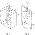
- Figure 1A shows an oblique view from above of a beverage container 51, which is shown with the front removed for clarity so that the inserted drinking straw 1 of a first example (see also Figure 1C ) is visible.
- an insertion device 53 with a first cross-sectional area 54 is provided, into which the drinking straw 1 with a second cross-sectional area 7, also referred to as cross-section 7 for short, is inserted.
- the first cross-sectional area 54 is designed similarly (similar in the mathematical sense) to the second cross-sectional area 7, ie the two cross-sectional areas 7, 54 have the same shape, whereby the first cross-sectional area 54 is larger than the second cross-sectional area 7.
- the first and second cross-sectional areas can also be the same size.
- the drinking straw 1 comprises a locking lug 2 and a tubular straw element 3, which comprises a straw wall 4, an inlet 5 to be placed in the beverage packaging and an outlet 6 to be placed outside the beverage packaging.
- the straw element 3 has a round cross-section 7.
- the insertion area 53 is surrounded by a reinforced area 55, which is designed here as a circular ring and extends from the insertion area over a ring width.
- FIG 1B a schematic view of a foil bag 64 with an inserted drinking straw 1 of the first example (see also Figure 1C ).
- an insertion device 66 with a first cross-sectional area 67 is provided, into which the drinking straw 1 with a second cross-sectional area 7, also referred to as cross-section 7 for short, is inserted.
- the first cross-sectional area 67 is designed similarly (similar in the mathematical sense) to the second cross-sectional area 7, i.e. the two cross-sectional areas 7, 67 have the same shape, but the first cross-sectional area 67 is larger than the second cross-sectional area 7.
- the insertion area 66 is surrounded by a reinforced area 68, which is designed here as a circular ring and extends from the insertion area over a ring width.
- the first and second cross-sectional areas can also be the same size.
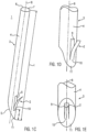
- the Figure 1C shows a schematic oblique view of the first example of the drinking straw 1 with a locking lug 2.
- the locking lug 2 was created by a three-sided cutout in the straw wall 4, so that the straw wall 4 has an opening 9, the dimensions of which correspond to the locking lug 2.
- the locking lug 2 can be regarded as a spread-out part of the stem wall 4.
- the locking lug 2 is provided on the outer surface of the straw wall 4. In the direction of the inlet 5, the locking lug 2 is connected to the outer surface of the straw wall 4, and in the direction of the outlet 6, an increasing spacing of the locking lug 2 from the outer surface of the straw wall 4 can be seen.
- the locking lug 2 is at a distance d from the inlet 5 along a longitudinal axis 8 of the drinking straw 1 of a maximum of 30% of a length I of the drinking straw 1.
- the drinking straw 1 shown comprises an insertion tip 11.
- the Figure 1D shows a schematic oblique view from the front of an area of the insertion tip 11 of the drinking straw 1 and the Figure 1E shows a schematic view from behind of the area of the insertion tip 11 of the drinking straw 1.
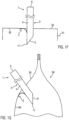
- FIG. 1F shows how the locking lug 2 of the drinking straw 1 can deform when an attempt is made to remove the drinking straw 1 from the beverage packaging 51.
- the locking lug 2 of the drinking straw 1 can deform when an attempt is made to remove the drinking straw 1 from the foil bag 64. If an attempt is made to pull the drinking straw 1 out of the foil bag 64 after the locking lug 2 has been inserted into the foil bag 64, the locking lug 2 interacts with the inner surface 69 of the foil bag 64 in an area around the insertion area 66 in such a way that the locking lug 2 is pressed against the inner surface 69 by pulling on the drinking straw 1, whereby its spacing from the outer surface of the straw wall 4 is partially increased. This partial increase in the spacing takes place where the locking lug 2 does not meet the outer surface of the straw wall 4.
- the locking lug 2 can therefore spread out from the outer surface of the straw wall 4 and function like a barb and can prevent the drinking straw 1 from being pulled out of the foil bag 64.
- the at least one locking lug of the different examples and the different embodiments of the drinking straws should have a distance from the inlet along a longitudinal axis of the drinking straw of a maximum of 30% of a length of the drinking straw.
- FIG. 2 This is shown schematically for a drinking straw 57, the inlet 58 of which has an insertion tip 59.
- the drinking straw 57 has a length l1 from the insertion tip 59 to an outlet 60.
- the area on a straw wall 61 that extends on a surface with a height of 0% of the length l1 up to 30% of the length l1 is shown hatched.
- a plane which runs through a region of the locking lug which is furthest away from the inlet e.g.
- the Figure 3 shows a schematic oblique view of a second example of a drinking straw 12 with two locking lugs 13.
- the drinking straw 12 is intended for a beverage packaging and comprises a tubular straw element 14 which comprises a straw wall 15, an inlet 16 to be placed in a beverage packaging and an outlet (not shown) to be placed outside the beverage packaging.
- the straw element 14 has an exemplary round cross section 95.
- the two locking lugs 13 are arranged opposite one another and each comprise a first part 17 which is fastened to the outer surface of the straw wall 15 and from which a second part 18 of the locking lug 13 extends, which has an increasing distance from the outer surface of the straw wall 15 in the direction of the outlet.
- the first part 17 extends from the inlet 16 towards the outlet and the second part 18 extends from an end of the first part 17 which is furthest away from the inlet 16 towards the outlet.
- the locking lugs 13 can thus be regarded as separate elements of the straw element 14, which are fastened to the first parts 17, for example by adhesive bonding to the straw wall 15 or in another liquid-resistant manner, for example by welding or sealing.
- the Figure 4A shows a schematic view from the front of an area of an insertion tip 20 of a third example of a drinking straw 19 with a locking lug 21.
- the drinking straw 19 is intended for a drinks package and comprises a tubular straw element 22 which comprises a straw wall 23, an inlet 24 to be placed in a drinks package and an outlet (not shown) to be placed outside the drinks package.
- the straw element 22 has an exemplary round cross section 25.
- the locking lug 21 comprises a first part 26 which is attached to the outer surface of the straw wall 23 and from which a second part 27 of the locking lug 21 extends, which has an increasing distance from the outer surface of the straw wall 23 in the direction of the outlet.
- the first part 26 extends from the insertion tip 20 towards the outlet and the second part 27 extends from an end of the first part 26 which is furthest away from the insertion tip 20 towards the outlet.
- the locking lug 21 can thus be regarded as a separate element of the straw element 22, which is attached to the first part 26, for example, by adhesive bonding to the straw wall 23 or in another liquid-resistant manner, for example by welding or sealing.
- the Figure 4B shows a schematic oblique view of the area of the insertion tip 20 of the drinking straw 19 of the Figure 4A .
- the Figure 5 a schematic oblique view of a fourth example of a drinking straw 28 with two locking lugs 29.
- the drinking straw 28 is intended for a drinks package and comprises a tubular straw element 30 which comprises a straw wall 31, an inlet 32 to be placed in a drinks package and an outlet (not shown) to be placed outside the drinks package.
- the straw element 30 has, by way of example, a round cross-section 33 and an insertion tip 34.
- the two locking lugs 29 are arranged opposite one another and each comprise a first part 35, which is arranged inside the straw element 30 and extends essentially to the longitudinal axis 39, and a second part 36, which is arranged outside the straw element 30.
- the locking lug 29 is inserted with the first part 35 into the interior of the straw element 30 through a cut 38 in the straw wall 31, which runs perpendicular to the longitudinal direction 39 of the drinking straw 28, in such a way that the first part 35 points in the direction of the inlet 32 and the second part 36 in the direction of the outlet.
- An acute angle is thereby formed between the locking lug 29 and the longitudinal axis 39.
- the application of an adhesive can be provided, which connects the locking lug 29 to the straw element 30.
- the first part 35 has a recess 37 at the end facing the inlet 32, which is designed in such a way, e.g. semicircular, that despite the two locking lugs 29 introduced into the straw element 30, a liquid transport through the interior of the straw element 30 is possible.
- the Figure 6A shows a schematic oblique view of a fifth example of a drinking straw 40 with two locking lugs 41.
- the drinking straw 40 is intended for a drinks package and comprises a tubular straw element 42 which comprises a straw wall 43, an inlet 44 to be placed in a drinks package and an outlet (not shown) to be placed outside the drinks package.
- the straw element 42 has, by way of example, a round cross-section 45 and an insertion tip 46.
- the two locking lugs 41 are arranged opposite one another and each comprise a first part 47, which is arranged in the interior of the straw element 42 and does not extend to the longitudinal axis 48, but for example has a minimal distance from the longitudinal axis that corresponds to half the radius of the drinking straw 40, and a second part 49, which is arranged outside the straw element 43.
- the locking lug 41 is inserted with the first part 47 into the interior of the straw element 42 through a cut 50 in the straw wall 43, which runs perpendicular to the longitudinal direction 45 of the drinking straw 40, in such a way that the first part 47 points in the direction of the inlet 44 and the second part 49 points in the direction of the outlet.
- An acute angle is enclosed between the locking lug 41 and the longitudinal axis 45.
- the application of an adhesive may be provided which connects the locking lug 41 to the straw element 42.
- FIG. 6B shows how the two locking lugs 41 of the drinking straw 40 of the fifth example can deform when an attempt is made to remove the drinking straw 40 from a drinks packaging 51. If an attempt is made to pull the drinking straw 40 out of the drinks packaging 51 after the locking lugs 41 have been inserted into the drinks packaging 51, the locking lugs 41 each interact with the inner surface 56 of the drinks packaging 51 in an area around the insertion area 53 in such a way that the locking lugs 41 are pressed against the inner surface 56 by pulling on the drinking straw 40, whereby the spacing of the second parts 49 of the locking lugs 41 from the outer surface of the straw wall 43 is partially increased.
- the locking lugs 41 can thus spread away from the outer surface of the stem wall 43 and thereby function like barbs and can prevent the drinking straw 40 from being pulled out of the beverage packaging 51 again.
- the first parts 47 of the locking lugs 41 which are arranged inside the straw element 42, can retain their shape, ie their shape is not influenced by the interaction of the second parts 49 with the inner surface 56 of the beverage packaging 51.
- FIG. 6C shows how the two locking lugs 41 of the drinking straw 40 of the fifth example can deform when an attempt is made to remove the drinking straw 40 from a foil bag 64. If an attempt is made to pull the drinking straw 40 out of the foil bag 64 after the locking lugs 41 have been inserted into the foil bag 64, the locking lugs 41 each interact with the inner surface 69 of the foil bag 64 in an area around the insertion area 66 in such a way that the locking lugs 41 are pressed against the inner surface 69 by pulling on the drinking straw 40, whereby the spacing of the second parts 49 of the locking lugs 41 from the outer surface of the straw wall 43 is partially increased.
- the locking lugs 41 can therefore spread out from the outer surface of the straw wall 43 and in doing so function like barbs and can prevent the drinking straw 40 from being pulled out of the foil bag 64.
- the first parts 47 of the locking lugs 41 which are arranged inside the straw element 42, can retain their shape, ie their shape is not influenced by the interaction of the second parts 49 with the inner surface 69 of the foil bag 64.
- FIG. 7A shows a schematic oblique view of an embodiment of a drinking straw 70 with a locking lug 76.
- the locking lug 76 was created by a two-sided cutout in the straw wall 72, so that the straw wall 72 has an opening 77, the dimensions of which correspond to the locking lug 76.
- the cut on both sides of the locking lug 76 can be created by a cutting process in which a knife or a blade or another cutting tool cuts into the drinking straw 70 at an angle to a longitudinal axis of the drinking straw 70 and in the process cuts through the straw wall 72 on both sides of the locking lug.
- the locking lug 76 is accordingly still connected to the straw wall 72.
- the locking lug 76 can be viewed as a splayed part of the straw wall 72.
- the locking lug 76 comprises a tip 78, which may, for example, additionally comprise a bend away from a longitudinal axis of the drinking straw, while, for example, the remaining region of the locking lug 76 does not comprise such a bend.
- the locking lug 76 is provided on the outer surface of the straw wall 72. In the direction of the inlet 73, the locking lug 76 is connected to the outer surface of the straw wall 72, and in the direction of the outlet 75, an increasing spacing of the locking lug 76 from the outer surface of the straw wall 72 can be seen.
- Such a locking lug 76 as in Figure 7A
- the advantage of the illustrated embodiment is that when the drinking straw is inserted into the beverage packaging, it can elastically deform inwards towards the middle of the drinking straw, so that the insertion process is not hindered. This is particularly due to the fact that the opening 77 corresponds in shape to the locking lug 76, so that the locking lug can be completely pressed elastically into the opening. As soon as the locking lug 76 is completely inside the beverage packaging, the locking lug can elastically deform outwards again.
- the locking lug 76 is spaced from the inlet 73 along a longitudinal axis of the drinking straw 70 by a maximum of 30% of a length of the drinking straw 70.
- the drinking straw 70 shown comprises an insertion tip 79.
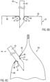
- Figure 7B shows schematically how the locking lug 76 can deform when an attempt is made to remove the drinking straw 70 from a beverage packaging 51. If an attempt is made to pull the drinking straw 70 out of the beverage packaging 51 after the locking lug 76 has been inserted into the beverage packaging 51, the locking lug 76 interacts with the inner surface 56 of the beverage packaging 51 in an area around the insertion area 53 in such a way that the locking lug 76 is pressed against the inner surface 56 by pulling on the drinking straw 70, whereby an area of the drinking straw 70 below, i.e. towards the inlet 73, bends. The locking lug 76 can therefore spread away from the outer surface of the straw wall 72 and function like a barb and can prevent the drinking straw 70 from being pulled out of the beverage packaging 51.
- the drinking straw 70 takes on a T-shaped configuration which very effectively prevents it from being pulled out, since the bent part of the drinking straw and the locking lug come to lie on different sides of the insertion area on the inner surface 68 of the beverage packaging, while the rest of the drinking straw protrudes from the insertion area and thus from the beverage packaging.
- FIG. 7C is shown how the locking lug 76 of the drinking straw 70 can deform when an attempt is made to remove the drinking straw 70 from the foil bag 64. If an attempt is made to pull the drinking straw 70 out of the foil bag 64 after the locking lug 76 has been inserted into the foil bag 64, the locking lug 76 interacts with the inner surface 69 of the foil bag 64 in an area around the insertion area 66 in such a way that the locking lug 76 is pushed through the Pulling on the drinking straw 70 presses it against the inner surface 69, whereby a portion of the drinking straw 70 bends underneath, ie towards the inlet 73.
- FIG 8A shows schematically a tubular straw element 80 on which a locking lug can be arranged.
- the straw element 80 comprises a straw wall 85, an inlet 83 to be placed in a beverage packaging with an inlet tip 84 and an outlet 81 to be placed outside the beverage packaging.
- the straw element 80 shown has a round cross section 82 with a diameter and a longitudinal axis 86. This longitudinal axis 86 is also referred to in the Figures 8B and 8D to describe the locking lugs that can be arranged on the straw element 80.
- FIG 8B shows schematically a first example of a locking lug 87 produced by means of an injection molding process.
- the locking lug 87 comprises a first part 88, which is designed here as an example as an open ring surface, wherein an inner diameter of the ring surface is equal to or up to 10% smaller than an outer diameter of the straw element 80, and a second part 89, which extends from the first part 88 away from the longitudinal axis 86. Due to the difference in diameter, the locking lug can elastically clamp itself onto the surface of the straw element 80.
- the inner diameter of the ring surface can also be up to 1% or 5% larger than the outer diameter of the straw element, wherein the locking lug then has to be connected to the drinking straw with additional measures such as welding, sealing or gluing.
- the first part 88 is designed in such a way that it surrounds the circumference of the straw element 80 by more than half; This makes it possible to clip the locking lug 87 onto the straw element 80.
- the second part 89 is designed to be wing-like, for example, but can also have other forms of locking lug, such as any form of barb.
- the wing-like example has the advantage that it rests against the wall of the drinking straw when the drinking straw is inserted into the beverage packaging, thus making it easy to insert the drinking straw into the beverage packaging.
- Figure 8C shows a drinking straw 90, wherein the straw element 80 from the Figure 8A the locking lug 87 from the Figure 8B is arranged.
- the locking lug 87 can be clipped onto the straw element by means of the first part 88. It is also possible to use a liquid-resistant adhesive.
- the locking lug 87 can then alternatively be welded or sealed onto the straw element 80. In other examples, more than one locking lug 87 can be arranged on the straw element 80.
- FIG 8D shows schematically a second example of a locking lug 91 produced by means of an injection molding process.
- the locking lug 91 comprises a first part 92 which is intended to be arranged on the outer surface of the straw wall 85 by welding or sealing, for example using a liquid-resistant adhesive.
- the first part 92 is designed such that it surrounds the circumference of the straw element 80 by less than half; thus, clipping this first part 92 onto the straw element 80 is not possible.
- the locking lug 91 comprises a second part 93 which extends from the first part 92 away from the longitudinal axis 86.
- the second part 93 is designed like a wing.
- Figure 8E shows a drinking straw 94, wherein the straw element 80 from the Figure 8A the locking lug 91 from the Figure 8D
- the first part 92 of the locking lug 91 can be connected to an outer surface of the straw wall 85 by welding or sealing.
- more than one locking lug 91 can be arranged on the straw element 80. It is also possible to arrange one or more locking lugs 87 of the first example and one or more locking lugs 91 of the second example on a straw element 80.
- the locking lugs produced by means of an injection molding process are also spaced from the inlet 83 along the longitudinal axis 86 of the straw element 80 by a maximum of 30% of the length of the straw element 80.
- the length of the straw element 80 and the length of a drinking straw comprising the straw element 80 and one or more locking lugs correspond to one another, i.e. they are the same size.
Landscapes
- Engineering & Computer Science (AREA)
- Mechanical Engineering (AREA)
- Packages (AREA)
Description
- Die vorliegende Erfindung betrifft eine Getränkeverpackung gemäß Anspruch 1.
-
EP 1 431 209 B1 offenbart eine Entnahmevorrichtung für Flüssigkeit in einer flexiblen Verpackung mit einem Halmelement, das ein Mundende und ein Beutelende umfasst, und mit einem Rastelement, das durch einen konisch zum Beutelende zulaufenden Kegelstumpf gebildet ist. Zwischen dem Mundende und dem Rastelement ist ein Ring angeordnet, durch dessen dem Beutelende zugewandte Ringfläche ein Anschlag gebildet ist. Der Abstand zwischen dem Anschlag und einer dem Mundende zugewandten Ringfläche des Rastelements ist derart bemessen, dass eine Hülle eines nicht dargestellten Getränkebeutels zwischen dem Anschlag und der Ringfläche aufgenommen werden kann. - Alternativ können an einer Hülse, in der die Entnahmevorrichtung aufgenommen ist, mehrere voneinander getrennte Raststege verteilt angeordnet sein, an deren Ende sich die Rastelemente befinden. Der Abstand zwischen der dem Mundende zugewandten Ringfläche des Rastelements und dem Anschlag ist derart gewählt, dass sich beim Hin- und Herschieben der Entnahmevorrichtung zwischen diesen beiden Flächen die dichtend an dem Halmelement anliegende Innenfolie nicht gegenüber dem Halmelement verschoben wird. Nach der Entleerung des Getränkebeutels kann die Entnahmevorrichtung aus diesem herausgezogen werden.
- Alternativ kann die Entnahmevorrichtung eine Hülse umfassen, die an ihrem zum Beutelende hin gerichteten Ende zwei Raststege aufweist, wobei benachbart zu den Raststegen und oberhalb der Raststege ein Ring ausgebildet ist und sich oberhalb des Rings sich in axialer Richtung erstreckende Griffstege in Umfangsrichtung verteilt angeordnet sind.
-
WO 2011/120037 A2 offenbart einen Trinkhalm, der verliersicher ausgebildet ist durch Vorsehen einer Hülse mit einer Vielzahl von fingerähnlichen Fortsätzen um die Außenwand des Trinkhalms, einer Vielzahl von Fortsätzen, die einteilig mit dem Trinkhalm sind, oder eines einteiligen Rückhalters aus einem dünnen, konusförmigen Material, das sich von der Außenwand des Trinkhalms wegerstreckt. -
KR 200 440 896 Y1 - Der Erfindung liegt somit die Aufgabe zugrunde, einen Trinkhalm und eine Getränkeverpackung zur Verfügung zu stellen, die einen Verbleib des Trinkhalms in einer Getränkeverpackung ermöglicht.
- Diese Aufgabe wird gelöst durch die Getränkeverpackung nach Anspruch 1. Bevorzugte Ausführungsformen und Weiterbildungen sind in den Unteransprüchen offenbart.
- Die Getränkeverpackung zur Aufnahme von flüssigem Produkt umfasst einen Einsteckbereich zum Einbringen eines Trinkhalms und den Trinkhalm. Der Trinkhalm umfasst ein rohrförmiges Halmelement, das eine Halmwandung, einen in die Getränkeverpackung zu platzierenden Einlass und einen außerhalb der Getränkeverpackung zu platzierenden Auslass umfasst. An einer äußeren Oberfläche der Halmwandung ist mindestens eine Rastnase in Form eines abgespreizten Teils vorgesehen, die zu dem Einlass hin mit der äußeren Oberfläche der Halmwandung verbunden ist und die zu dem Auslass hin von der äußeren Oberfläche der Halmwandung beabstandet ist. Die mindestens eine Rastnase weist von dem Einlass einen Abstand entlang einer Längsachse des Trinkhalms von maximal 30% einer Länge des Trinkhalms auf. Die mindestens eine Rastnase wird durch einen zweiseitigen Schnitt in der Halmwandung erzeugt.
- Durch das Vorsehen mindestens einer Rastnase im unteren Bereich eines Trinkhalms kann ein Verlieren des Trinkhalms, nachdem er in die Getränkeverpackung eingebracht wurde, vermieden werden, wobei der Trinkhalm jedoch noch in einem erheblichen Maße auf und ab bewegt werden kann, was die Flüssigkeitsentnahme vereinfacht.
- Dabei kann zwischen der Rastnase und der Längsachse ein spitzer Winkel eingeschlossen werden.
- Die mindestens eine Rastnase kann derart vorgesehen sein, dass sie bei einem Einbringen des Trinkhalms durch den Einsteckbereich in die Getränkeverpackung beim Passieren des Einsteckbereichs reversibel an die Halmwandung, d.h. das Halmelement, angedrückt werden kann. Beim Passieren des Einsteckbereichs kann keine oder kaum eine Beabstandung der mindestens einen Rastnase von der äußeren Oberfläche der Halmwandung vorhanden sein.
- Nachdem die mindestens eine Rastnase den Einsteckbereich passiert hat, sich also ganz innerhalb der Getränkeverpackung befindet, kann die mindestens eine Rastnase wieder in ihre Ausgangslage relativ zu der äußeren Oberfläche der Halmwandung zurückgehen.
- Wird versucht, den Trinkhalm nach einem Einbringen der mindestens einen Rastnase in die Getränkeverpackung wieder aus der Getränkeverpackung herauszuziehen, so kann die mindestens eine Rastnase derart mit der Innenfläche der Getränkeverpackung in einem Gebiet um den Einsteckbereich herum interagieren, dass sie durch das Ziehen am Trinkhalm gegen die Innenfläche gedrückt werden kann. Beispielsweise kann ihre Beabstandung von der äußeren Oberfläche der Halmwandung teilweise vergrößert werden oder aber auch gleichbleiben. Die mindestens eine Rastnase kann wie ein Widerhaken funktionieren und verhindern, dass der Trinkhalm wieder aus der Getränkeverpackung herausgezogen wird.
- Beispielhaft und nicht erfindungsgemäß kann die mindestens eine Rastnase ein abgespreizter Teil der Halmwandung sein. Die Rastnase kann durch einen dreiseitigen Ausschnitt in der Halmwandung erzeugt werden, so dass die Halmwandung eine Öffnung aufweisen kann, die in ihren Dimensionen der Rastnase entsprechen kann; beispielsweise kann eine Oberfläche, wenn sie als eine ebene Fläche ausgebreitet wird, der Rastnase rechteckig oder trapezförmig ausgebildet sein. Erfindungsgemäß wird die Rastnase durch einen zweiseitigen Schnitt in der Halmwandung erzeugt, beispielsweise in dem eine Schneidevorrichtung schräg, z.B. mit einem spitzen Winkel bezüglich der Längsachse, an der Halmwandung angesetzt und ein Schnitt in der Halmwandung in Richtung des Einlasses durchgeführt wird. Dann kann beispielsweise eine Oberfläche, wenn sie als eine ebene Fläche ausgebreitet wird, dieser Rastnase dreieckig ausgebildet sein. Wird versucht, einen Trinkhalm nach einem Einbringen der Rastnase, die durch einen zweiseitigen Schnitt in der Halmwandung erzeugt wurde, in die Getränkeverpackung aus der Getränkeverpackung herauszuziehen, so kann die Rastnase derart mit der Innenfläche der Getränkeverpackung in einem Gebiet um einen Einsteckbereich herum interagieren, dass die Rastnase durch das Ziehen am Trinkhalm gegen die Innenfläche der Getränkeverpackung gedrückt wird, wodurch ein Bereich des Trinkhalms unterhalb, d.h. zum Einlass hin, abknickt. Der Trinkhalm, der aus der Getränkeverpackung heraussteht, der abgeknickte Teil und die Rastnase bilden dabei eine T-Form die ein Herausziehen des Trinkhalmes effektiv verhindert.
- Vorzugsweise ist die Öffnung und somit auch die Rastnase in den verschiedenen Ausführungsformen derart bemessen, dass der Flüssigkeitsaustritt vom Inneren des Halmelements durch die Öffnung hinaus nicht die Funktionalität des Trinkhalms negativ beeinflusst. In den zuvor erwähnten Ausführungsbeispielen kann die Rastnase dementsprechend an einer Seite der Öffnung noch mit der Halmwandung verbunden sein (die vierte Seite des Rechtecks oder Trapezes bzw. die dritte Seite des Dreiecks). Beispielweise kann ein Endbereich der Rastnase, das Richtung Auslass weist, zusätzlich eine Biegung weg, z.B. krallenartig, von der Längsachse umfassen, während beispielsweise der restliche Bereich der Rastnase keine derartige Biegung umfasst.
- Beispielhaft und nicht erfindungsgemäß kann die mindestens eine Rastnase ein in einen Schnitt der Halmwandung eingestecktes und befestigtes Element sein. Dabei kann zwischen der Rastnase und der Längsachse ein spitzer Winkel eingeschlossen werden. Der Schnitt in der Halmwandung kann quer, beispielsweise senkrecht, zu der Längsrichtung des Trinkhalms verlaufen, d.h. sich beispielsweise entlang eines Umfangbereichs der Halmwandung erstrecken.
- Beispielhaft und nicht erfindungsgemäß kann das Element einen ersten Teil, der sich in einen Innenbereich des Halmelements erstreckt, und einen zweiten Teil, der sich außerhalb des Halmelements erstreckt, umfassen, wobei beispielsweise der erste Teil einen Ausschnitt umfassen kann, der ausgelegt ist, eine Flüssigkeitspassage im Innenbereich des Halmelements zu ermöglichen. Dabei kann zwischen der Rastnase und der Längsachse ein spitzer Winkel eingeschlossen werden. Dadurch, dass sich die Rastnase bis ins Innere des Halmelements erstreckt, kann die Stabilität der Rastnase hinsichtlich Verbiegungen bei einem Versuch den Trinkhalm wieder aus der Getränkeverpackung herauszuziehen verbessert werden.
- Beispielhaft und nicht erfindungsgemäß kann die mindestens eine Rastnase einen ersten Teil umfassen, der auf der äußeren Oberfläche der Halmwandung befestigt sein kann und von dem ausgehend sich ein zweiter Teil der Rastnase erstrecken kann, der zu dem Auslass hin von der äußeren Oberfläche der Halmwandung beabstandet sein kann. Dabei kann zwischen der Rastnase und der Längsachse ein spitzer Winkel eingeschlossen werden. Die Befestigung der Rastnase auf der äußeren Oberfläche kann in einer einfachen Weise erfolgen.
- Beispielhaft und nicht erfindungsgemäß kann der erste Teil an dem Einlass beginnen und sich von dem Einlass ausgehend in Richtung Auslass erstrecken. Beispielsweise kann der erste Teil an einer Einsteckspitze des Einlasses beginnen.
- Der Einlass kann eine Einsteckspitze umfassen.
- Beispielhaft und nicht erfindungsgemäß kann die mindestens eine Rastnase mit einem Spritzgussverfahren hergestellt werden, beispielsweise separat von dem Halmelement. Die Rastnase kann dann in geeigneter Weise an dem Halmelement befestigt oder in es eingesteckt und dann befestigt werden, beispielsweise mittels eines flüssigkeitsresistenten Klebemittels, beispielsweise mittels Anclipsen, Anschweißen oder Ansiegeln. Ein Anclipsen kann auch ohne Verwendung eines flüssigkeitsresistenten Klebemittels erfolgen.
- Der Trinkhalm kann mit einem Spritzgussverfahren hergestellt werden. So können das Halmelement und die Rastnase oder die Rastnasen einstückig hergestellt werden. Das Halmelement und die Rastnase oder die Rastnasen können auch jeweils separat hergestellt werden. Bei einer separaten Herstellung kann die Rastnase oder können die Rastnasen mittels Anclipsen, Anschweißen oder Ansiegeln mit dem Halmelement zumindest teilweise verbunden werden.
- Ein Querschnitt des Halmelements kann rund, oval, dreieckig oder viereckig ausgebildet sein.
- Eine Querschnittsfläche des Einsteckbereichs und eine Querschnittsfläche des Halmelements, unter Berücksichtigung einer Wanddicke der Halmwandung, können ähnlich sein, wobei die Querschnittsfläche des Einsteckbereichs 1% bis 100%, (oder auch 30% bis 70%) größer sein kann als die Querschnittsfläche des Halmelements, unter der Berücksichtigung der Wanddicke der Halmwandung. Die Berücksichtigung der Wanddicke kann bedeuten, dass zu dem Innenquerschnitt des Halmelements der Wandquerschnitt hinzugezählt wird. Im Falle eines runden Innenquerschnitts des Halmelements kann der Wandquerschnitt einem Kreisring eine Ringbreite aufweisen, die der Wanddicke entspricht.
- Der Einsteckbereich kann von einem verstärkten Bereich umgeben sein. So kann ein Einreisen des Einsteckbereichs bei einem Versuch den Trinkhalm wieder aus der Getränkeverpackung herauszuziehen vor einem Einreißen geschützt werden.
- Die Getränkeverpackung kann als Getränkekarton, als Folienbeutel oder Standbodenbeutel ausgebildet sein.
- Die beigefügten Figuren stellen beispielhaft zum besseren Verständnis und zur Veranschaulichung Aspekte und Ausführungsformen der Erfindung dar. Es zeigt:
-
Figur 1A eine schematische Ansicht einer Getränkeverpackung mit eingebrachtem Trinkhalm, -
Figur 1B eine schematische Ansicht eines Folienbeutels mit eingebrachtem Trinkhalm, -
Figur 1C eine schematische Schrägansicht des ersten Beispiels des Trinkhalms mit einer Rastnase, -
Figur 1D eine schematische Schrägansicht von vorne auf einen Bereich der Einsteckspitze des Trinkhalms, -
Figur 1E eine schematische Ansicht von hinten auf den Bereich der Einsteckspitze des Trinkhalms, -
Figur 1F schematisch, wie sich die Rastnase verformt bei einem Versuch, den Trinkhalm aus der Getränkeverpackung derFigur 1A zu entfernen, -
Figur 1G schematisch, wie sich die Rastnase verformt bei einem Versuch, den Trinkhalm aus dem Folienbeutel derFigur 1B zu entfernen, -
Figur 2 den Bereich an einem Trinkhalm, in dem Rastnasen angeordnet sein können, -
Figur 3 eine schematische Schrägansicht eines zweiten Beispiels eines Trinkhalms mit zwei Rastnasen, -
Figur 4A eine schematische Ansicht von vorne auf einen Bereich einer Einsteckspitze eines dritten Beispiels eines Trinkhalms mit einer Rastnase, -
Figur 4B eine schematische Schrägansicht auf den Bereich der Einsteckspitze des Trinkhalms derFigur 4A , -
Figur 5 eine schematische Schrägansicht eines vierten Beispiels eines Trinkhalms mit zwei Rastnasen und -
Figur 6A eine schematische Schrägansicht eines fünften Beispiels eines Trinkhalms mit zwei Rastnasen, -
Figur 6B schematisch, wie sich die beiden Rastnasen verformen bei einem Versuch, den Trinkhalm derFigur 6A aus einer Getränkeverpackung zu entfernen, -
Figur 6C schematisch, wie sich die beiden Rastnasen verformen bei einem Versuch, den Trinkhalm derFigur 6A aus einem Folienbeutel zu entfernen, -
Figur 7A eine schematische Schrägansicht einer Ausführungsform eines Trinkhalms mit einer Rastnase, -
Figur 7B schematisch, wie sich die Rastnase verformt bei einem Versuch, den Trinkhalm derFigur 7A aus einer Getränkeverpackung zu entfernen, -
Figur 7C schematisch, wie sich die Rastnase verformt bei einem Versuch, den Trinkhalm derFigur 7A aus einem Folienbeutel zu entfernen, -
Figur 8A schematisch ein rohrförmiges Halmelement, an dem eine Rastnase anordenbar ist, -
Figur 8B schematisch ein erstes Beispiel einer mittels Spritzgussverfahrens hergestellter Rastnase, -
Figur 8C die an dem Halmelement ausFigur 8A angeordnete Rastnase ausFigur 8B , -
Figur 8D schematisch ein zweites Beispiel einer mittels Spritzgussverfahrens hergestellter Rastnase, -
Figur 8E die an dem Halmelement ausFigur 8A angeordnete Rastnase ausFigur 8D . - Die
Figuren 1A bis 6C und dieFiguren 8A bis 8E stellen nicht erfindungsgemäße Aspekte dar und dienen lediglich der Veranschaulichung. -
Figur 1A zeigt eine Schrägansicht von oben auf einen Getränkebehälter 51, der der Übersichtlichkeit wegen mit entfernter Frontseite dargestellt ist, damit der eingebrachte Trinkhalm 1 eines ersten Beispiels (siehe auchFigur 1C ) sichtbar ist. Auf einer Oberseite 52 des Getränkebehälters 51 ist eine Einsteckvorrichtung 53 mit einer ersten Querschnittsfläche 54 vorgesehen, in die der Trinkhalm 1 mit einer zweiten Querschnittsfläche 7, kurz auch als Querschnitt 7 bezeichnet, eingebracht ist. Die erste Querschnittsfläche 54 ist ähnlich (ähnlich im mathematischen Sinn) zu der zweiten Querschnittsfläche 7ausgebildet, d.h. die beiden Querschnittsflächen 7, 54 weisen eine gleiche Gestalt auf, wobei die erste Querschnittsfläche 54 aber größer ausgebildet ist als die zweite Querschnittsfläche 7. Die erste und die zweite Querschnittsfläche können aber auch gleich groß ausgebildet sein. - In dem ersten Beispiel umfasst der Trinkhalm 1 eine Rastnase 2 und ein rohrförmiges Halmelement 3, das eine Halmwandung 4, einen in der Getränkeverpackung zu platzierenden Einlass 5 und einen außerhalb der Getränkeverpackung zu platzierenden Auslass 6 umfasst. In der Darstellung weist das Halmelement 3 einen runden Querschnitt 7 auf.
- Der Einsteckbereich 53 ist von einem verstärkten Bereich 55 umgeben, der hier als Kreisring ausgebildet ist und sich ausgehend von dem Einsteckbereich über eine Ringbreite hinweg erstreckt.
-
Figur 1B eine schematische Ansicht eines Folienbeutels 64 mit einem eingebrachten Trinkhalm 1 des ersten Beispiels (siehe auchFigur 1C ). Auf einer Beutelseite 65 ist eine Einsteckvorrichtung 66 mit einer ersten Querschnittsfläche 67 vorgesehen, in die der Trinkhalm 1 mit einer zweiten Querschnittsfläche 7, kurz auch als Querschnitt 7 bezeichnet, eingebracht ist. Die erste Querschnittsfläche 67 ist ähnlich (ähnlich im mathematischen Sinn) zu der zweiten Querschnittsfläche 7 ausgebildet, d.h. die beiden Querschnittsflächen 7, 67 weisen eine gleiche Gestalt auf, wobei die erste Querschnittsfläche 67 aber größer ausgebildet ist als die zweite Querschnittsfläche 7. Der Einsteckbereich 66 ist von einem verstärkten Bereich 68 umgeben, der hier als Kreisring ausgebildet ist und sich ausgehend von dem Einsteckbereich über eine Ringbreite hinweg erstreckt. Die erste und die zweite Querschnittsfläche können aber auch gleich groß ausgebildet sein. - Die
Figur 1C zeigt eine schematische Schrägansicht des ersten Beispiels des Trinkhalms 1 mit einer Rastnase 2. Die Rastnase 2 wurde durch einen dreiseitigen Ausschnitt in der Halmwandung 4 erzeugt, so dass die Halmwandung 4 eine Öffnung 9 aufweist, die in ihren Dimensionen der Rastnase 2 entspricht. An einer Seite 10 der Öffnung 9 ist die Rastnase 2 dementsprechend noch mit der Halmwandung 4 verbunden. Die Rastnase 2 kann als ein abgespreizter Teil der Halmwandung 4 angesehen werden. - Die Rastnase 2 ist an der äußeren Oberfläche der Halmwandung 4 vorgesehen. In Richtung zu dem Einlass 5 hin ist die Rastnase 2 mit der äußeren Oberfläche der Halmwandung 4 verbunden, und in Richtung zu dem Auslass 6 hin ist eine zunehmende Beabstandung der Rastnase 2 von der äußeren Oberfläche der Halmwandung 4 zu erkennen.
- Die Rastnase 2 weist von dem Einlass 5 einen Abstand d entlang einer Längsachse 8 des Trinkhalms 1 von maximal 30% einer Länge I des Trinkhalms 1 auf. Der dargestellte Trinkhalm 1 umfasst eine Einsteckspitze 11.
- Die
Figur 1D zeigt eine schematische Schrägansicht von vorne auf einen Bereich der Einsteckspitze 11 des Trinkhalms 1 und dieFigur 1E zeigt eine schematische Ansicht von hinten auf den Bereich der Einsteckspitze 11 des Trinkhalms 1. - In der
Figur 1F ist dargestellt, wie sich die Rastnase 2 des Trinkhalms 1 verformen kann, wenn versucht wird, den Trinkhalm 1 wieder aus der Getränkeverpackung 51 zu entfernen. Wird versucht, den Trinkhalm 1 nach einem Einbringen der Rastnase 2 in die Getränkeverpackung 51 aus der Getränkeverpackung 51 herauszuziehen, so interagiert die Rastnase 2 derart mit der Innenfläche 56 der Getränkeverpackung 51 in einem Gebiet um den Einsteckbereich 53 herum, dass die Rastnase 2 durch das Ziehen am Trinkhalm 1 gegen die Innenfläche 56 gedrückt wird, wodurch ihre Beabstandung von der äußeren Oberfläche der Halmwandung 4 teilweise vergrößert wird. Diese teilweise Vergrößerung der Beabstandung findet dabei dort statt, wo die Rastnase 2 nicht mit der äußeren Oberfläche der Halmwandung 4 verbunden ist. Die Rastnase 2 kann sich also von der äußeren Oberfläche der Halmwandung 4 abspreizen und dabei wie ein Widerhaken funktionieren und kann verhindern, dass der Trinkhalm 1 wieder aus der Getränkeverpackung 51 herausgezogen wird. - In der
Figur 1G ist dargestellt, wie sich die Rastnase 2 des Trinkhalms 1 verformen kann, wenn versucht wird, den Trinkhalm 1 wieder aus dem Folienbeutel 64 zu entfernen. Wird versucht, den Trinkhalm 1 nach einem Einbringen der Rastnase 2 in den Folienbeutel 64 aus dem Folienbeutel 64 herauszuziehen, so interagiert die Rastnase 2 derart mit der Innenfläche 69 des Folienbeutels 64 in einem Gebiet um den Einsteckbereich 66 herum, dass die Rastnase 2 durch das Ziehen am Trinkhalm 1 gegen die Innenfläche 69 gedrückt wird, wodurch ihre Beabstandung von der äußeren Oberfläche der Halmwandung 4 teilweise vergrößert wird. Diese teilweise Vergrößerung der Beabstandung findet dabei dort statt, wo die Rastnase 2 nicht mit der äußeren Oberfläche der Halmwandung 4 verbunden ist. Die Rastnase 2 kann sich also von der äußeren Oberfläche der Halmwandung 4 abspreizen und dabei wie ein Widerhaken funktionieren und kann verhindern, dass der Trinkhalm 1 wieder aus dem Folienbeutel 64 herausgezogen wird. Allgemein soll die mindestens eine Rastnase der unterschiedlichen Beispiele und der unterschiedlichen Ausführungsformen der Trinkhalme von dem Einlass einen Abstand entlang einer Längsachse des Trinkhalms von maximal 30% einer Länge des Trinkhalms aufweisen. - In der
Figur 2 ist dies für einen Trinkhalm 57 schematisch dargestellt, dessen Einlass 58 eine Einsteckspitze 59 aufweist. Von der Einsteckspitze 59 ausgehend bis zu einem Auslass 60 weist der Trinkhalm 57 eine Länge l1 auf. Schraffiert dargestellt ist der Bereich auf einer Halmwandung 61, der sich auf einer Mantelfläche mit einer Höhe von 0% der Länge l1 bis zu 30% der Länge l1 erstreckt. Beispielsweise kann vorgesehen sein, dass eine Ebene, die durch einen am weitesten von dem Einlass entfernten Bereich (z.B. eine Kante der Rastnase oder eine Spitze der Rastnase) der Rastnase verläuft und die senkrecht zu der Längsachse 62 ist, den Trinkhalm in einer Höhe h ausgehend von der Einsteckspitze 59 schneidet, die kleiner oder gleich 30% der Länge 11. Alternativ kann vorgesehen sein, dass eine Ebene, die durch einen Bereich geht, wo die Rastnase 63 beginnt von der äußeren Oberfläche der Halmwandung 61 abzustehen, und die senkrecht zu der Längsachse 62 ist, den Trinkhalm in einer Höhe h1 ausgehend von der Einsteckspitze 59 schneidet, die kleiner oder gleich 30% der Länge l1 ist. - Die
Figur 3 zeigt eine schematische Schrägansicht eines zweiten Beispiels eines Trinkhalms 12 mit zwei Rastnasen 13. Der Trinkhalm 12 ist für eine Getränkeverpackung vorgesehen und umfasst ein rohrförmiges Halmelement 14, das eine Halmwandung 15, einen in einer Getränkeverpackung zu platzierenden Einlass 16 und einen außerhalb der Getränkeverpackung zu platzierenden Auslass (nicht dargestellt) umfasst. In der Darstellung weist das Halmelement 14 exemplarisch einen runden Querschnitt 95 auf. - Die zwei Rastnasen 13 sind einander gegenüberliegend angeordnet und umfassen jeweils einen ersten Teil 17, der auf der äußeren Oberfläche der Halmwandung 15 befestigt ist und von dem ausgehend sich ein zweiter Teil 18 der Rastnase 13 erstreckt, der in Richtung zu dem Auslass hin eine zunehmende Beabstandung von der äußeren Oberfläche der Halmwandung 15 aufweist. Der erste Teil 17 erstreckt sich von dem Einlass 16 ausgehend Richtung Auslass und der zweite Teil 18 erstreckt sich ausgehend von einem Ende des ersten Teils 17, das von dem Einlass 16 am weitesteten entfernt ist, Richtung Auslass. Die Rastnasen 13 können somit als separate Elemente des Halmelements 14 angesehen werden, die mit den ersten Teilen 17 beispielsweise auf die Halmwandung 15 aufgeklebt oder in anderer flüssigkeitsresistenter Weise befestigt sind, beispielsweise mittels Anschweißen oder Ansiegeln.
- Die
Figur 4A zeigt eine schematische Ansicht von vorne auf einen Bereich einer Einsteckspitze 20 eines dritten Beispiels eines Trinkhalms 19 mit einer Rastnase 21. Der Trinkhalm 19 ist für eine Getränkeverpackung vorgesehen und umfasst ein rohrförmiges Halmelement 22, das eine Halmwandung 23, einen in einer Getränkeverpackung zu platzierenden Einlass 24 und einen außerhalb der Getränkeverpackung zu platzierenden Auslass (nicht dargestellt) umfasst. In der Darstellung weist das Halmelement 22 exemplarisch einen runden Querschnitt 25 auf. - Die Rastnase 21 umfasst einen ersten Teil 26, der auf der äußeren Oberfläche der Halmwandung 23 befestigt ist und von dem ausgehend sich ein zweiter Teil 27 der Rastnase 21 erstreckt, der in Richtung zu dem Auslass hin eine zunehmende Beabstandung von der äußeren Oberfläche der Halmwandung 23 aufweist. Der erste Teil 26 erstreckt sich ausgehend von der Einsteckspitze 20 ausgehend Richtung Auslass und der zweite Teil 27 erstreckt sich ausgehend von einem Ende des ersten Teils 26, das von der Einsteckspitze 20 am weitesteten entfernt ist, Richtung Auslass. Die Rastnase 21 kann somit als separates Elemente des Halmelements 22 angesehen werden, die mit dem ersten Teil 26 beispielsweise auf die Halmwandung 23 aufgeklebt oder in anderer flüssigkeitsresistenter Weise befestigt sind, beispielsweise mittels Anschweißen oder Ansiegeln.
- Die
Figur 4B zeigt eine schematische Schrägansicht auf den Bereich der Einsteckspitze 20 des Trinkhalms 19 derFigur 4A . - Die
Figur 5 eine schematische Schrägansicht eines vierten Beispiels eines Trinkhalms 28 mit zwei Rastnasen 29. Der Trinkhalm 28 ist für eine Getränkeverpackung vorgesehen und umfasst ein rohrförmiges Halmelement 30, das eine Halmwandung 31, einen in einer Getränkeverpackung zu platzierenden Einlass 32 und einen außerhalb der Getränkeverpackung zu platzierenden Auslass (nicht dargestellt) umfasst. In der Darstellung weist das Halmelement 30 exemplarisch einen runden Querschnitt 33 und eine Einsteckspitze 34 auf. - Die zwei Rastnasen 29 sind einander gegenüberliegend angeordnet und umfassen jeweils einen ersten Teil 35, der im Innern des Halmelements 30 angeordnet ist und sich im Wesentlichen bis zur Längsachse 39 erstreckt, und einen zweiten Teil 36, der außerhalb des Halmelements 30 angeordnet ist. Die Rastnase 29 ist durch einen Schnitt 38 in der Halmwandung 31, der senkrecht zu der Längsrichtung 39 des Trinkhalms 28 verläuft, mit dem ersten Teil 35 in das Innere des Halmelements 30 derart eingeschoben, dass der erste Teil 35 in Richtung Einlass 32 und der zweite Teil 36 Richtung Auslass weist. Dabei wird zwischen der Rastnase 29 und der Längsachse 39 ein spitzer Winkel eingeschlossen. Im Bereich um den Schnitt 38 kann das Anbringen eines Klebemittels vorgesehen sein, das die Rastnase 29 mit dem Halmelement 30 verbindet
- Der erste Teil 35 weist an dem Ende, das dem Einlass 32 zugewandt ist, eine Ausnehmung 37 auf, die derart, z.B. Halbkreisförmig, ausgebildet ist, dass trotz der beiden in das Halmelement 30 eingebrachten Rastnasen 29 ein Flüssigkeitstransport durch das Innere des Halmelements 30 möglich ist.
- Die
Figur 6A zeigt eine schematische Schrägansicht eines fünften Beispiels eines Trinkhalms 40 mit zwei Rastnasen 41. Der Trinkhalm 40 ist für eine Getränkeverpackung vorgesehen und umfasst ein rohrförmiges Halmelement 42, das eine Halmwandung 43, einen in einer Getränkeverpackung zu platzierenden Einlass 44 und einen außerhalb der Getränkeverpackung zu platzierenden Auslass (nicht dargestellt) umfasst. In der Darstellung weist der das Halmelement 42 exemplarisch einen runden Querschnitt 45 und eine Einsteckspitze 46 auf. - Die zwei Rastnasen 41 sind einander gegenüberliegend angeordnet und umfassen jeweils einen ersten Teil 47, der im Innern des Halmelements 42 angeordnet ist und sich nicht bis zur Längsachse 48 erstreckt, sondern z. B. einen minimalen Abstand zur Längsachse hat, der der Hälfte des Radiuses des Trinkhalms 40 entspricht, und einen zweiten Teil 49, der außerhalb des Halmelements 43 angeordnet ist. Die Rastnase 41 ist durch einen Schnitt 50 in der Halmwandung 43, der senkrecht zu der Längsrichtung 45 des Trinkhalms 40 verläuft, mit dem ersten Teil 47 in das Innere des Halmelements 42 derart eingeschoben, dass der erste Teil 47 in Richtung Einlass 44 und der zweite Teil 49 Richtung Auslass weist. Dabei wird zwischen der Rastnase 41 und der Längsachse 45 ein spitzer Winkel eingeschlossen. Im Bereich um den Schnitt 50 kann das Anbringen eines Klebemittels vorgesehen sein, das die Rastnase 41 mit dem Halmelement 42 verbindet.
- Da die beiden ersten Teile 47 von der Längsachse 45 beabstandet sind, ist ein Flüssigkeitstransport durch das Innere des Halmelements 42 möglich.
- In der
Figur 6B ist dargestellt, wie sich die zwei Rastnasen 41 des Trinkhalms 40 des fünften Beispiels verformen können, wenn versucht wird, den Trinkhalm 40 wieder aus einer Getränkeverpackung 51 zu entfernen. Wird versucht, den Trinkhalm 40 nach einem Einbringen der Rastnasen 41 in die Getränkeverpackung 51 aus der Getränkeverpackung 51 herauszuziehen, so interagieren die Rastnasen 41 jeweils derart mit der Innenfläche 56 der Getränkeverpackung 51 in einem Gebiet um den Einsteckbereich 53 herum, dass die Rastnasen 41 durch das Ziehen am Trinkhalm 40 gegen die Innenfläche 56 gedrückt werden, wodurch die Beabstandung der zweiten Teile 49 der Rastnasen 41 von der äußeren Oberfläche der Halmwandung 43 teilweise vergrößert wird. Diese teilweise Vergrößerung der Beabstandung findet dabei dort statt, wo der zweite Teil 49 der Rastnasen 41 nicht mit der äußeren Oberfläche der Halmwandung 43 verbunden ist. Die Rastnasen 41 können sich also von der äußeren Oberfläche der Halmwandung 43 abspreizen und dabei wie Widerhaken funktionieren und können verhindern, dass der Trinkhalm 40 wieder aus der Getränkeverpackung 51 herausgezogen wird. Die ersten Teile 47 der Rastnasen 41, die im Innern des Halmelements 42 angeordnet sind, können ihre Form beibehalten, d.h., ihre Form wird nicht durch die Interaktion der zweiten Teile 49 mit der Innenfläche 56 der Getränkeverpackung 51 beeinflusst. - In der
Figur 6C ist dargestellt, wie sich die zwei Rastnasen 41 des Trinkhalms 40 des fünften Beispiels verformen können, wenn versucht wird, den Trinkhalm 40 wieder aus einem Folienbeutel 64 zu entfernen. Wird versucht, den Trinkhalm 40 nach einem Einbringen der Rastnasen 41 in den Folienbeutel 64 aus dem Folienbeutel 64 herauszuziehen, so interagieren die Rastnasen 41 jeweils derart mit der Innenfläche 69 des Folienbeutels 64 in einem Gebiet um den Einsteckbereich 66 herum, dass die Rastnasen 41 durch das Ziehen am Trinkhalm 40 gegen die Innenfläche 69 gedrückt werden, wodurch die Beabstandung der zweiten Teile 49 der Rastnasen 41 von der äußeren Oberfläche der Halmwandung 43 teilweise vergrößert wird. Diese teilweise Vergrößerung der Beabstandung findet dabei dort statt, wo der zweite Teil 49 der Rastnasen 41 nicht mit der äußeren Oberfläche der Halmwandung 43 verbunden ist. Die Rastnasen 41 können sich also von der äußeren Oberfläche der Halmwandung 43 abspreizen und dabei wie Widerhaken funktionieren und können verhindern, dass der Trinkhalm 40 wieder aus dem Folienbeutel 64 herausgezogen wird. Die ersten Teile 47 der Rastnasen 41, die im Innern des Halmelements 42 angeordnet sind, können ihre Form beibehalten, d.h., ihre Form wird nicht durch die Interaktion der zweiten Teile 49 mit der Innenfläche 69 des Folienbeutels 64 beeinflusst. -
Figur 7A zeigt eine schematische Schrägansicht einer Ausführungsform eines Trinkhalms 70 mit einer Rastnase 76. Die Rastnase 76 wurde durch einen zweiseitigen Ausschnitt in der Halmwandung 72 erzeugt, so dass die Halmwandung 72 eine Öffnung 77 aufweist, die in ihren Dimensionen der Rastnase 76 entspricht. Der Schnitt auf beiden Seiten der Rastnase 76 kann durch einen Schneidvorgang erzeugt werden, bei dem ein Messer oder eine Klinge oder ein sonstiges Schneidwerkzeug schräg zu einer Längsachse des Trinkhalms 70 in den Trinkhalm 70 hineinschneidet und dabei die Halmwandung 72 an beiden Seiten der Rastnase durchtrennt. An einer Seite der Öffnung 77 ist die Rastnase 76 dementsprechend noch mit der Halmwandung 72 verbunden. Die Rastnase 76 kann als ein abgespreizter Teil der Halmwandung 72 angesehen werden. Die Rastnase 76 umfasst eine Spitze 78, die beispielsweise zusätzlich eine Biegung weg von einer Längsachse des Trinkhalms umfassen kann, während beispielsweise der restliche Bereich der Rastnase 76 keine derartige Biegung umfasst. - Die Rastnase 76 ist an der äußeren Oberfläche der Halmwandung 72 vorgesehen. In Richtung zu dem Einlass 73 hin ist die Rastnase 76 mit der äußeren Oberfläche der Halmwandung 72 verbunden, und in Richtung zu dem Auslass 75 hin ist eine zunehmende Beabstandung der Rastnase 76 von der äußeren Oberfläche der Halmwandung 72 zu erkennen.
- Eine solche Rastnase 76, wie in
Figur 7A dargestellt hat den Vorteil, dass diese sich beim Einstecken des Trinkhalmes in die Getränkeverpackung nach innen in Richtung der Mitte des Trinkhalmes elastisch verformen kann, so dass der Einsteckvorgang nicht behindert wird. Dies ergibt sich insbesondere dadurch, dass die Öffnung 77 in ihrer Form der Rastnase 76 entspricht, so dass die Rastnase vollständig in die Öffnung elastisch hineingedrückt werden kann. Sobald die Rastnase 76 vollständig im Inneren der Getränkeverpackung ist, kann die Rastnase sich wieder elastisch nach außen verformen. - Die Rastnase 76 weist von dem Einlass 73 einen Abstand entlang einer Längsachse des Trinkhalms 70 von maximal 30% einer Länge des Trinkhalms 70 auf. Der dargestellte Trinkhalm 70 umfasst eine Einsteckspitze 79.
-
Figur 7B zeigt schematisch, wie sich die Rastnase 76 verformen kann, wenn versucht wird, den Trinkhalm 70 wieder aus einer Getränkeverpackung 51 zu entfernen. Wird versucht, den Trinkhalm 70 nach einem Einbringen der Rastnase 76 in die Getränkeverpackung 51 aus der Getränkeverpackung 51 herauszuziehen, so interagiert die Rastnase 76 derart mit der Innenfläche 56 der Getränkeverpackung 51 in einem Gebiet um den Einsteckbereich 53 herum, dass die Rastnase 76 durch das Ziehen am Trinkhalm 70 gegen die Innenfläche 56 gedrückt wird, wodurch ein Bereich des Trinkhalms 70 unterhalb, d.h. zum Einlass 73 hin, abknickt. Die Rastnase 76 kann sich also von der äußeren Oberfläche der Halmwandung 72 abspreizen und dabei wie ein Widerhaken funktionieren und kann verhindern, dass der Trinkhalm 70 wieder aus der Getränkeverpackung 51 herausgezogen wird. Der Trinkhalm 70 nimmt dabei eine T-förmige Gestalt an, die ein Herausziehen sehr effektiv verhindert, da der abgeknickte Teil des Trinkhalmes und die Rastnase auf verschiedenen Seiten des Einsteckbereichs an der Innenfläche 68 der Getränkeverpackung zu liegen kommen, während der Rest des Trinkhalmes aus dem Einsteckbereich und damit aus der Getränkeverpackung herausragt. - In
Figur 7C ist dargestellt, wie sich die Rastnase 76 des Trinkhalms 70 verformen kann, wenn versucht wird, den Trinkhalm 70 wieder aus dem Folienbeutel 64 zu entfernen. Wird versucht, den Trinkhalm 70 nach einem Einbringen der Rastnase 76 in den Folienbeutel 64 aus dem Folienbeutel 64 herauszuziehen, so interagiert die Rastnase 76 derart mit der Innenfläche 69 des Folienbeutels 64 in einem Gebiet um den Einsteckbereich 66 herum, dass die Rastnase 76 durch das Ziehen am Trinkhalm 70 gegen die Innenfläche 69 gedrückt wird, wodurch ein Bereich des Trinkhalms 70 unterhalb, d.h. zum Einlass 73 hin, abknickt. Die Rastnase 76 kann sich also von der äußeren Oberfläche der Halmwandung 72 abspreizen und dabei wie ein Widerhaken funktionieren und kann verhindern, dass der Trinkhalm 70 wieder aus dem Folienbeutel 64 herausgezogen wird.Figur 8A zeigt schematisch ein rohrförmiges Halmelement 80, an dem eine Rastnase anordenbar ist. Das Halmelement 80 umfasst eine Halmwandung 85, einen in einer Getränkeverpackung zu platzierenden Einlass 83 mit einer Einlassspitze 84 und einer außerhalb der Getränkeverpackung zu platzierenden Auslass 81. Das dargestellte Halmelement 80 weist einen runden Querschnitt 82 mit einem Durchmesser und eine Längsachse 86 auf. Auf diese Längsachse 86 wird auch in denFiguren 8B und 8D verwiesen, um die Rastnasen, die an dem Halmelement 80 anordenbar sind, zu beschreiben. -
Figur 8B zeigt schematisch ein erstes Beispiel einer mittels eines Spritzgussverfahrens hergestellten Rastnase 87. Die Rastnase 87 umfasst einen ersten Teil 88, der hier beispielhaft als eine offene Ringfläche ausgebildet ist, wobei ein Innendurchmesser der Ringfläche gleich oder bis zu 10% kleiner ist als ein Außendurchmesser des Halmelements 80, und einen zweiten Teil 89, der von dem ersten Teil 88 ausgehend sich von der Längsachse 86 weg erstreckt. Durch den Durchmesserunterschied kann die Rastnase sich auf der Halmoberfläche des Halmelements 80 elastisch festspannen. Der Innendurchmesser der Ringfläche kann aber auch bis zu 1% oder 5% größer sein als der Außendurchmesser des Halmelements, wobei die Rastnase dann noch mit zusätzlichen Maßnahmen wie Anschweißen, Siegeln oder Kleben mit dem Trinkhalm verbunden werden muss. Der erste Teil 88 ist derart ausgebildet, dass er den Umfang des Halmelements 80 um mehr als die Hälfte umgibt; so ist ein Anclipsen der Rastnase 87 an dem Halmelement 80 möglich. Der zweite Teil 89 ist beispielsweise flügelartig ausgebildet, kann aber auch andere Formen einer Rastnase haben, wie beispielsweise jegliche Form eines Widerhakens. Das flügelartige Beispiel hat den Vorteil, dass diese sich beim Einstecken des Trinkhalms in die Getränkeverpackung an die Wandung des Trinkhalmes anleget und so ein leichtes Einführen des Trinkhalms in die Getränkeverpackung ermöglicht wird. -
Figur 8C zeigt einen Trinkhalm 90, wobei an dem Halmelement 80 aus derFigur 8A die Rastnase 87 aus derFigur 8B angeordnet ist. Die Rastnase 87 kann mittels des ersten Teils 88 an dem Halmelement angeclipst werden. Auch ein Verwenden eines flüssigkeitsresistenten Klebemittels ist möglich. Dann kann die Rastnase 87 an dem Halmelement 80 alternativ auch angeschweißt oder angesiegelt werden. In anderen Beispielen kann auch mehr als eine Rastnase 87 an dem Halmelement 80 angeordnet werden. -
Figur 8D zeigt schematisch ein zweites Beispiel einer mittels eines Spritzgussverfahrens hergestellten Rastnase 91. Die Rastnase 91 umfasst einen ersten Teil 92, der vorgesehen ist, mit der äußeren Oberfläche der Halmwandung 85 durch Anschweißen oder Ansiegeln angeordnet zu werden, beispielsweise unter Verwendung eines flüssigkeitsresistenten Klebemittels. In der Darstellung ist der erste Teil 92 derart ausgebildet, dass er den Umfang des Halmelements 80 um weniger als die Hälfte umgibt; somit ist ein Anclipsen dieses ersten Teils 92 an dem Halmelement 80 nicht möglich. Die Rastnase 91 umfasst einen zweiten Teil 93, der von dem ersten Teil 92 ausgehend sich von der Längsachse 86 weg erstreckt. Der zweite Teil 93 ist flügelartig ausgebildet. -
Figur 8E zeigt einen Trinkhalm 94, wobei an dem Halmelement 80 aus derFigur 8A die Rastnase 91 aus derFigur 8D angeordnet ist. Der erste Teil 92 der Rastnase 91 kann durch Anschweißen oder Ansiegeln mit einer äußeren Oberfläche der Halmwandung 85 verbunden werden. - In anderen Beispielen kann auch mehr als eine Rastnase 91 an dem Halmelement 80 angeordnet werden. Auch ein Anordnen von einer oder mehreren Rastnasen 87 des ersten Beispiels und von einer oder mehreren Rastnasen 91 des zweiten Beispiels an einem Halmelement 80 ist möglich.
- Auch für die mittels eines Spritzgussverfahrens hergestellten Rastnasen gilt, dass sie von dem Einlass 83 einen Abstand entlang der Längsachse 86 des Halmelements 80 von maximal 30% einer Länge des Halmelements 80 aufweisen. Die Länge des Halmelements 80 und die Länge eines Trinkhalms, der das Halmelement 80 und eine oder mehrere Rastnasen umfasst, entsprechen einander, d.h., sie sind gleich groß.
Claims (9)
- Getränkeverpackung zur Aufnahme von flüssigem Produkt, wobei die Getränkeverpackung (51) einen Einsteckbereich (53) zum Einbringen eines Trinkhalms (70) und den Trinkhalm (70) umfasst,wobei der Trinkhalm (70) ein rohrförmiges Halmelement (71) umfasst, das eine Halmwandung (72), einen in der Getränkeverpackung (51) zu platzierenden Einlass (73) und einen außerhalb der Getränkeverpackung (51) zu platzierenden Auslass (74) umfasst,wobei an einer äußeren Oberfläche der Halmwandung (72) mindestens eine Rastnase in Form eines abgespreizten Teils (76) vorgesehen ist, die zu dem Einlass (73) hin mit der äußeren Oberfläche der Halmwandung (72) verbunden ist und die zu dem Auslass (74) hin von der äußeren Oberfläche der Halmwandung (72) beabstandet ist, wobei die mindestens eine Rastnase (76) von dem Einlass (73) einen Abstand entlang einer Längsachse des Trinkhalms (70) von maximal 30% einer Länge des Trinkhalms (70) aufweist,dadurch gekennzeichnet, dassdie mindestens eine Rastnase (76) durch einen zweiseitigen Schnitt in der Halmwandung (72) erzeugt wird.
- Die Getränkeverpackung nach Anspruch 1, wobei zur Erzeugung des zweiseitigen Schnitts eine Schneidevorrichtung schräg an der Halmwandung (72) angesetzt und ein Schnitt in der Halmwandung (72) in Richtung des Einlasses (73) durchgeführt wird.
- Die Getränkeverpackung nach Anspruch 1 oder 2, wobei der Trinkhalm (70) und die Getränkeverpackung (51) so ausgebildet sind, dass der in die Getränkeverpackung (51) so eingesteckte Trinkhalm (70), dass die Rastnase (76) vollständig in die Getränkeverpackung (51) eingeführt ist, sich beim Versuch, diesen Trinkhalm (70) aus der Getränkeverpackung (51) herauszuziehen, so verformt, dass ein Rausziehen verhindert wird, wobei dies beispielsweise dadurch erreicht wird, dass das Trinkhalmende, welches beim Einlass (73) des Trinkhalms (70) vorgesehen ist, abknickt.
- Die Getränkeverpackung nach einem der Ansprüche 1 bis 3, wobei der Einlass (73) eine Einsteckspitze (79) umfasst.
- Die Getränkeverpackung nach einem der Ansprüche 1 bis 4, wobei der Trinkhalm (70)) mit einem Spritzgussverfahren hergestellt ist.
- Die Getränkeverpackung nach einem der Ansprüche 1 bis 5, wobei eine Querschnittsfläche (75) des Halmelements (71) rund, oval, dreieckig oder viereckig ausgebildet ist.
- Die Getränkeverpackung nach einem der Ansprüche 1 bis 6, wobei eine Querschnittsfläche (54) des Einsteckbereichs (53) und eine Querschnittsfläche (75) des Halmelements (71), unter Berücksichtigung einer Wanddicke der Halmwandung (72), ähnlich sind, wobei die Querschnittsfläche (54) des Einsteckbereichs (53) gleich groß wie oder 1 % bis 100% größer oder 30% bis 70% größer ist als die Querschnittsfläche (75) des Halmelements (71), unter der Berücksichtigung der Wanddicke der Halmwandung (72).
- Die Getränkeverpackung nach einem der Ansprüche 1 bis 7, wobei der Einsteckbereich (53) von einem verstärkten Bereich (55) umgeben ist.
- Die Getränkeverpackung nach einem der Ansprüche 1 bis 8, wobei die Getränkeverpackung (51) als Getränkekarton, als Folienbeutel oder Standbodenbeutel ausgebildet ist.
Applications Claiming Priority (2)
| Application Number | Priority Date | Filing Date | Title |
|---|---|---|---|
| EP19153467.6A EP3685710A1 (de) | 2019-01-24 | 2019-01-24 | Getränkeverpackung mit trinkhalm |
| PCT/EP2019/084910 WO2020151874A1 (de) | 2019-01-24 | 2019-12-12 | Getränkeverpackung |
Publications (2)
| Publication Number | Publication Date |
|---|---|
| EP3914130A1 EP3914130A1 (de) | 2021-12-01 |
| EP3914130B1 true EP3914130B1 (de) | 2024-07-31 |
Family
ID=65236860
Family Applications (2)
| Application Number | Title | Priority Date | Filing Date |
|---|---|---|---|
| EP19153467.6A Withdrawn EP3685710A1 (de) | 2019-01-24 | 2019-01-24 | Getränkeverpackung mit trinkhalm |
| EP19816771.0A Active EP3914130B1 (de) | 2019-01-24 | 2019-12-12 | Getränkeverpackung mit trinkhalm |
Family Applications Before (1)
| Application Number | Title | Priority Date | Filing Date |
|---|---|---|---|
| EP19153467.6A Withdrawn EP3685710A1 (de) | 2019-01-24 | 2019-01-24 | Getränkeverpackung mit trinkhalm |
Country Status (10)
| Country | Link |
|---|---|
| US (1) | US20220087457A1 (de) |
| EP (2) | EP3685710A1 (de) |
| KR (1) | KR102717043B1 (de) |
| CN (1) | CN113395920B (de) |
| CA (1) | CA3124601A1 (de) |
| MX (1) | MX2021008178A (de) |
| PL (1) | PL3914130T3 (de) |
| SA (1) | SA521422606B1 (de) |
| TW (1) | TW202028078A (de) |
| WO (1) | WO2020151874A1 (de) |
Families Citing this family (2)
| Publication number | Priority date | Publication date | Assignee | Title |
|---|---|---|---|---|
| USD979424S1 (en) | 2021-03-09 | 2023-02-28 | Antrim Acres, Ltd. | Beverage pouch |
| US12466625B1 (en) | 2023-04-21 | 2025-11-11 | Coral Spirits LLC | Fluid container |
Citations (1)
| Publication number | Priority date | Publication date | Assignee | Title |
|---|---|---|---|---|
| EP3692865A1 (de) * | 2019-02-06 | 2020-08-12 | Tetra Laval Holdings & Finance S.A. | Trinkhalm, verpackungsanordnung und verfahren zur herstellung eines trinkhalms |
Family Cites Families (11)
| Publication number | Priority date | Publication date | Assignee | Title |
|---|---|---|---|---|
| JPH01164873U (de) * | 1988-05-09 | 1989-11-17 | ||
| DE19819574A1 (de) | 1998-04-30 | 1999-11-04 | Sisi Werke Gmbh | Entnahmevorrichtung für Flüssigkeit in einer flexiblen Verpackung und flexible Verpackung zur Aufnahme von Flüssigkeit |
| JP3796643B2 (ja) * | 1999-04-28 | 2006-07-12 | 敬久 藤内 | 飲料吸引具 |
| KR100383453B1 (ko) * | 2000-07-19 | 2003-05-14 | 주식회사 삼보기술단 | 락 볼트 시공용 고정구 |
| KR20070120762A (ko) * | 2006-06-20 | 2007-12-26 | 임의순 | 역류방지용 빨대 |
| KR200440896Y1 (ko) * | 2008-03-06 | 2008-07-07 | 김광호 | 빠짐 방지 빨대 |
| WO2011120037A2 (en) * | 2010-03-26 | 2011-09-29 | Wallace Jamie M | Drinking straw |
| NL2007236C2 (en) * | 2011-08-09 | 2013-02-12 | Bin Innovations Bv | Carton plug for retaining a straw in a drinking carton, drinking carton, and method for facilitating drinking from a drinking carton. |
| CN202365526U (zh) * | 2011-12-14 | 2012-08-08 | 王迎春 | 吸管 |
| CN202515285U (zh) * | 2012-03-02 | 2012-11-07 | 卢淼 | 一种防儿童误食的安全吸管 |
| CN205585787U (zh) * | 2016-01-12 | 2016-09-21 | 深圳市威尔王子投资有限公司 | 可滤式吸管 |
-
2019
- 2019-01-24 EP EP19153467.6A patent/EP3685710A1/de not_active Withdrawn
- 2019-12-12 WO PCT/EP2019/084910 patent/WO2020151874A1/de not_active Ceased
- 2019-12-12 CN CN201980089062.5A patent/CN113395920B/zh active Active
- 2019-12-12 US US17/425,665 patent/US20220087457A1/en not_active Abandoned
- 2019-12-12 CA CA3124601A patent/CA3124601A1/en active Pending
- 2019-12-12 PL PL19816771.0T patent/PL3914130T3/pl unknown
- 2019-12-12 EP EP19816771.0A patent/EP3914130B1/de active Active
- 2019-12-12 MX MX2021008178A patent/MX2021008178A/es unknown
- 2019-12-12 KR KR1020217026277A patent/KR102717043B1/ko active Active
- 2019-12-30 TW TW108148324A patent/TW202028078A/zh unknown
-
2021
- 2021-07-24 SA SA521422606A patent/SA521422606B1/ar unknown
Patent Citations (1)
| Publication number | Priority date | Publication date | Assignee | Title |
|---|---|---|---|---|
| EP3692865A1 (de) * | 2019-02-06 | 2020-08-12 | Tetra Laval Holdings & Finance S.A. | Trinkhalm, verpackungsanordnung und verfahren zur herstellung eines trinkhalms |
Also Published As
| Publication number | Publication date |
|---|---|
| TW202028078A (zh) | 2020-08-01 |
| WO2020151874A1 (de) | 2020-07-30 |
| CN113395920B (zh) | 2022-12-13 |
| MX2021008178A (es) | 2021-11-12 |
| US20220087457A1 (en) | 2022-03-24 |
| KR102717043B1 (ko) | 2024-10-15 |
| EP3914130A1 (de) | 2021-12-01 |
| SA521422606B1 (ar) | 2023-02-08 |
| CA3124601A1 (en) | 2020-07-30 |
| KR20210117312A (ko) | 2021-09-28 |
| EP3685710A1 (de) | 2020-07-29 |
| PL3914130T3 (pl) | 2024-12-16 |
| CN113395920A (zh) | 2021-09-14 |
Similar Documents
| Publication | Publication Date | Title |
|---|---|---|
| DE2901061C2 (de) | Verschlußplombe | |
| EP0128525B1 (de) | Auslaufsperre für Behälter, insbesondere für Tuben, und Anwendungen | |
| DE69013931T2 (de) | Vorrichtung zur entnahme von flüssigem füllmaterial durch eine flexible beutelwand. | |
| DE4330052A1 (de) | Verschlußverfahren und Verschlußvorrichtung | |
| WO2020089148A1 (de) | Verschlusskappe zum verschliessen eines behälters | |
| DE19855577B4 (de) | Verpackung für chirurgisches Nahtmaterial | |
| DE10121899A1 (de) | Einteiliger Zuschnitt für eine Faltschachtel | |
| CH715953A2 (de) | Verschlusskappe zum Verschliessen eines Behälters und Behälter mit einer solchen unverlierbar gehaltenen Verschlusskappe. | |
| WO2020182852A1 (de) | Verschlusskappe zum verschliessen eines behälters | |
| EP3873821A1 (de) | Verschlusskappe zum verschliessen eines behälters | |
| EP3938289A1 (de) | Verschlusskappe zum verschliessen eines behälters | |
| CH643079A5 (de) | Handschliessplombe. | |
| WO2020229103A1 (de) | Umreifungsgebinde und verfahren zu dessen herstellung | |
| WO2015036167A1 (de) | Behälterdose und halteeinrichtung | |
| EP3685710A1 (de) | Getränkeverpackung mit trinkhalm | |
| DE102018125344A1 (de) | Verschlussvorrichtung für einen Tuchspender | |
| DE102013007063A1 (de) | Behältnis | |
| EP3504129B1 (de) | Schnappverschluss mit originalitätssicherheit | |
| EP0436083A1 (de) | Abfüllstutzen aus Kunststoff | |
| DE102011012048A1 (de) | Kettenbeutel | |
| WO2009111899A1 (de) | Selbstöffnerverschluss mit lufteinlass | |
| EP3822189A1 (de) | Verpackung, verpackungseinheit für eine verpackung und verfahren zur herstellung einer verpackung | |
| EP4153527B1 (de) | Adapter zum verbinden eines nachfüllbehälters | |
| CH524515A (de) | Behälter | |
| EP4115776B1 (de) | Verfahren zum zumindest teilweisen verschliessen einer hauptöffnung eines trinkhalmes |
Legal Events
| Date | Code | Title | Description |
|---|---|---|---|
| STAA | Information on the status of an ep patent application or granted ep patent |
Free format text: STATUS: UNKNOWN |
|
| STAA | Information on the status of an ep patent application or granted ep patent |
Free format text: STATUS: THE INTERNATIONAL PUBLICATION HAS BEEN MADE |
|
| PUAI | Public reference made under article 153(3) epc to a published international application that has entered the european phase |
Free format text: ORIGINAL CODE: 0009012 |
|
| STAA | Information on the status of an ep patent application or granted ep patent |
Free format text: STATUS: REQUEST FOR EXAMINATION WAS MADE |
|
| 17P | Request for examination filed |
Effective date: 20210824 |
|
| AK | Designated contracting states |
Kind code of ref document: A1 Designated state(s): AL AT BE BG CH CY CZ DE DK EE ES FI FR GB GR HR HU IE IS IT LI LT LU LV MC MK MT NL NO PL PT RO RS SE SI SK SM TR |
|
| DAV | Request for validation of the european patent (deleted) | ||
| DAX | Request for extension of the european patent (deleted) | ||
| P01 | Opt-out of the competence of the unified patent court (upc) registered |
Effective date: 20230524 |
|
| STAA | Information on the status of an ep patent application or granted ep patent |
Free format text: STATUS: EXAMINATION IS IN PROGRESS |
|
| 17Q | First examination report despatched |
Effective date: 20230721 |
|
| GRAP | Despatch of communication of intention to grant a patent |
Free format text: ORIGINAL CODE: EPIDOSNIGR1 |
|
| STAA | Information on the status of an ep patent application or granted ep patent |
Free format text: STATUS: GRANT OF PATENT IS INTENDED |
|
| INTG | Intention to grant announced |
Effective date: 20240301 |
|
| GRAS | Grant fee paid |
Free format text: ORIGINAL CODE: EPIDOSNIGR3 |
|
| GRAA | (expected) grant |
Free format text: ORIGINAL CODE: 0009210 |
|
| STAA | Information on the status of an ep patent application or granted ep patent |
Free format text: STATUS: THE PATENT HAS BEEN GRANTED |
|
| AK | Designated contracting states |
Kind code of ref document: B1 Designated state(s): AL AT BE BG CH CY CZ DE DK EE ES FI FR GB GR HR HU IE IS IT LI LT LU LV MC MK MT NL NO PL PT RO RS SE SI SK SM TR |
|
| REG | Reference to a national code |
Ref country code: CH Ref legal event code: EP Ref country code: GB Ref legal event code: FG4D Free format text: NOT ENGLISH |
|
| REG | Reference to a national code |
Ref country code: DE Ref legal event code: R096 Ref document number: 502019011807 Country of ref document: DE |
|
| REG | Reference to a national code |
Ref country code: IE Ref legal event code: FG4D Free format text: LANGUAGE OF EP DOCUMENT: GERMAN |
|
| REG | Reference to a national code |
Ref country code: NL Ref legal event code: FP |
|
| REG | Reference to a national code |
Ref country code: LT Ref legal event code: MG9D |
|
| PG25 | Lapsed in a contracting state [announced via postgrant information from national office to epo] |
Ref country code: PT Free format text: LAPSE BECAUSE OF FAILURE TO SUBMIT A TRANSLATION OF THE DESCRIPTION OR TO PAY THE FEE WITHIN THE PRESCRIBED TIME-LIMIT Effective date: 20241202 |
|
| PG25 | Lapsed in a contracting state [announced via postgrant information from national office to epo] |
Ref country code: PT Free format text: LAPSE BECAUSE OF FAILURE TO SUBMIT A TRANSLATION OF THE DESCRIPTION OR TO PAY THE FEE WITHIN THE PRESCRIBED TIME-LIMIT Effective date: 20241202 |
|
| PG25 | Lapsed in a contracting state [announced via postgrant information from national office to epo] |
Ref country code: NO Free format text: LAPSE BECAUSE OF FAILURE TO SUBMIT A TRANSLATION OF THE DESCRIPTION OR TO PAY THE FEE WITHIN THE PRESCRIBED TIME-LIMIT Effective date: 20241031 |
|
| PG25 | Lapsed in a contracting state [announced via postgrant information from national office to epo] |
Ref country code: FI Free format text: LAPSE BECAUSE OF FAILURE TO SUBMIT A TRANSLATION OF THE DESCRIPTION OR TO PAY THE FEE WITHIN THE PRESCRIBED TIME-LIMIT Effective date: 20240731 Ref country code: GR Free format text: LAPSE BECAUSE OF FAILURE TO SUBMIT A TRANSLATION OF THE DESCRIPTION OR TO PAY THE FEE WITHIN THE PRESCRIBED TIME-LIMIT Effective date: 20241101 |
|
| PGFP | Annual fee paid to national office [announced via postgrant information from national office to epo] |
Ref country code: BE Payment date: 20241218 Year of fee payment: 6 Ref country code: NL Payment date: 20241227 Year of fee payment: 6 Ref country code: PL Payment date: 20241129 Year of fee payment: 6 |
|
| PGFP | Annual fee paid to national office [announced via postgrant information from national office to epo] |
Ref country code: GB Payment date: 20241220 Year of fee payment: 6 |
|
| PG25 | Lapsed in a contracting state [announced via postgrant information from national office to epo] |
Ref country code: BG Free format text: LAPSE BECAUSE OF FAILURE TO SUBMIT A TRANSLATION OF THE DESCRIPTION OR TO PAY THE FEE WITHIN THE PRESCRIBED TIME-LIMIT Effective date: 20240731 |
|
| PGFP | Annual fee paid to national office [announced via postgrant information from national office to epo] |
Ref country code: FR Payment date: 20241221 Year of fee payment: 6 |
|
| PG25 | Lapsed in a contracting state [announced via postgrant information from national office to epo] |
Ref country code: LV Free format text: LAPSE BECAUSE OF FAILURE TO SUBMIT A TRANSLATION OF THE DESCRIPTION OR TO PAY THE FEE WITHIN THE PRESCRIBED TIME-LIMIT Effective date: 20240731 |
|
| PG25 | Lapsed in a contracting state [announced via postgrant information from national office to epo] |
Ref country code: IS Free format text: LAPSE BECAUSE OF FAILURE TO SUBMIT A TRANSLATION OF THE DESCRIPTION OR TO PAY THE FEE WITHIN THE PRESCRIBED TIME-LIMIT Effective date: 20241130 |
|
| PGFP | Annual fee paid to national office [announced via postgrant information from national office to epo] |
Ref country code: AT Payment date: 20241218 Year of fee payment: 6 |
|
| PG25 | Lapsed in a contracting state [announced via postgrant information from national office to epo] |
Ref country code: HR Free format text: LAPSE BECAUSE OF FAILURE TO SUBMIT A TRANSLATION OF THE DESCRIPTION OR TO PAY THE FEE WITHIN THE PRESCRIBED TIME-LIMIT Effective date: 20240731 |
|
| PGFP | Annual fee paid to national office [announced via postgrant information from national office to epo] |
Ref country code: CZ Payment date: 20241202 Year of fee payment: 6 |
|
| PG25 | Lapsed in a contracting state [announced via postgrant information from national office to epo] |
Ref country code: RS Free format text: LAPSE BECAUSE OF FAILURE TO SUBMIT A TRANSLATION OF THE DESCRIPTION OR TO PAY THE FEE WITHIN THE PRESCRIBED TIME-LIMIT Effective date: 20241031 Ref country code: ES Free format text: LAPSE BECAUSE OF FAILURE TO SUBMIT A TRANSLATION OF THE DESCRIPTION OR TO PAY THE FEE WITHIN THE PRESCRIBED TIME-LIMIT Effective date: 20240731 |
|
| PG25 | Lapsed in a contracting state [announced via postgrant information from national office to epo] |
Ref country code: RS Free format text: LAPSE BECAUSE OF FAILURE TO SUBMIT A TRANSLATION OF THE DESCRIPTION OR TO PAY THE FEE WITHIN THE PRESCRIBED TIME-LIMIT Effective date: 20241031 Ref country code: NO Free format text: LAPSE BECAUSE OF FAILURE TO SUBMIT A TRANSLATION OF THE DESCRIPTION OR TO PAY THE FEE WITHIN THE PRESCRIBED TIME-LIMIT Effective date: 20241031 Ref country code: LV Free format text: LAPSE BECAUSE OF FAILURE TO SUBMIT A TRANSLATION OF THE DESCRIPTION OR TO PAY THE FEE WITHIN THE PRESCRIBED TIME-LIMIT Effective date: 20240731 Ref country code: IS Free format text: LAPSE BECAUSE OF FAILURE TO SUBMIT A TRANSLATION OF THE DESCRIPTION OR TO PAY THE FEE WITHIN THE PRESCRIBED TIME-LIMIT Effective date: 20241130 Ref country code: HR Free format text: LAPSE BECAUSE OF FAILURE TO SUBMIT A TRANSLATION OF THE DESCRIPTION OR TO PAY THE FEE WITHIN THE PRESCRIBED TIME-LIMIT Effective date: 20240731 Ref country code: GR Free format text: LAPSE BECAUSE OF FAILURE TO SUBMIT A TRANSLATION OF THE DESCRIPTION OR TO PAY THE FEE WITHIN THE PRESCRIBED TIME-LIMIT Effective date: 20241101 Ref country code: FI Free format text: LAPSE BECAUSE OF FAILURE TO SUBMIT A TRANSLATION OF THE DESCRIPTION OR TO PAY THE FEE WITHIN THE PRESCRIBED TIME-LIMIT Effective date: 20240731 Ref country code: ES Free format text: LAPSE BECAUSE OF FAILURE TO SUBMIT A TRANSLATION OF THE DESCRIPTION OR TO PAY THE FEE WITHIN THE PRESCRIBED TIME-LIMIT Effective date: 20240731 Ref country code: BG Free format text: LAPSE BECAUSE OF FAILURE TO SUBMIT A TRANSLATION OF THE DESCRIPTION OR TO PAY THE FEE WITHIN THE PRESCRIBED TIME-LIMIT Effective date: 20240731 |
|
| PGFP | Annual fee paid to national office [announced via postgrant information from national office to epo] |
Ref country code: TR Payment date: 20241209 Year of fee payment: 6 |
|
| PGFP | Annual fee paid to national office [announced via postgrant information from national office to epo] |
Ref country code: DE Payment date: 20241218 Year of fee payment: 6 |
|
| PG25 | Lapsed in a contracting state [announced via postgrant information from national office to epo] |
Ref country code: DK Free format text: LAPSE BECAUSE OF FAILURE TO SUBMIT A TRANSLATION OF THE DESCRIPTION OR TO PAY THE FEE WITHIN THE PRESCRIBED TIME-LIMIT Effective date: 20240731 Ref country code: RO Free format text: LAPSE BECAUSE OF FAILURE TO SUBMIT A TRANSLATION OF THE DESCRIPTION OR TO PAY THE FEE WITHIN THE PRESCRIBED TIME-LIMIT Effective date: 20240731 Ref country code: SM Free format text: LAPSE BECAUSE OF FAILURE TO SUBMIT A TRANSLATION OF THE DESCRIPTION OR TO PAY THE FEE WITHIN THE PRESCRIBED TIME-LIMIT Effective date: 20240731 |
|
| PG25 | Lapsed in a contracting state [announced via postgrant information from national office to epo] |
Ref country code: EE Free format text: LAPSE BECAUSE OF FAILURE TO SUBMIT A TRANSLATION OF THE DESCRIPTION OR TO PAY THE FEE WITHIN THE PRESCRIBED TIME-LIMIT Effective date: 20240731 |
|
| PGFP | Annual fee paid to national office [announced via postgrant information from national office to epo] |
Ref country code: CH Payment date: 20250101 Year of fee payment: 6 |
|
| PG25 | Lapsed in a contracting state [announced via postgrant information from national office to epo] |
Ref country code: IT Free format text: LAPSE BECAUSE OF FAILURE TO SUBMIT A TRANSLATION OF THE DESCRIPTION OR TO PAY THE FEE WITHIN THE PRESCRIBED TIME-LIMIT Effective date: 20240731 Ref country code: SK Free format text: LAPSE BECAUSE OF FAILURE TO SUBMIT A TRANSLATION OF THE DESCRIPTION OR TO PAY THE FEE WITHIN THE PRESCRIBED TIME-LIMIT Effective date: 20240731 |
|
| REG | Reference to a national code |
Ref country code: DE Ref legal event code: R097 Ref document number: 502019011807 Country of ref document: DE |
|
| PLBE | No opposition filed within time limit |
Free format text: ORIGINAL CODE: 0009261 |
|
| STAA | Information on the status of an ep patent application or granted ep patent |
Free format text: STATUS: NO OPPOSITION FILED WITHIN TIME LIMIT |
|
| PG25 | Lapsed in a contracting state [announced via postgrant information from national office to epo] |
Ref country code: MC Free format text: LAPSE BECAUSE OF FAILURE TO SUBMIT A TRANSLATION OF THE DESCRIPTION OR TO PAY THE FEE WITHIN THE PRESCRIBED TIME-LIMIT Effective date: 20240731 |
|
| 26N | No opposition filed |
Effective date: 20250501 |
|
| PG25 | Lapsed in a contracting state [announced via postgrant information from national office to epo] |
Ref country code: LU Free format text: LAPSE BECAUSE OF NON-PAYMENT OF DUE FEES Effective date: 20241212 |
|
| PG25 | Lapsed in a contracting state [announced via postgrant information from national office to epo] |
Ref country code: SE Free format text: LAPSE BECAUSE OF FAILURE TO SUBMIT A TRANSLATION OF THE DESCRIPTION OR TO PAY THE FEE WITHIN THE PRESCRIBED TIME-LIMIT Effective date: 20240731 |
|
| PG25 | Lapsed in a contracting state [announced via postgrant information from national office to epo] |
Ref country code: IE Free format text: LAPSE BECAUSE OF NON-PAYMENT OF DUE FEES Effective date: 20241212 |
|
| PG25 | Lapsed in a contracting state [announced via postgrant information from national office to epo] |
Ref country code: CY Free format text: LAPSE BECAUSE OF FAILURE TO SUBMIT A TRANSLATION OF THE DESCRIPTION OR TO PAY THE FEE WITHIN THE PRESCRIBED TIME-LIMIT Effective date: 20240731 |