EP3912935B1 - Zweischichtiger linearer sortierer - Google Patents
Zweischichtiger linearer sortierer Download PDFInfo
- Publication number
- EP3912935B1 EP3912935B1 EP20741893.0A EP20741893A EP3912935B1 EP 3912935 B1 EP3912935 B1 EP 3912935B1 EP 20741893 A EP20741893 A EP 20741893A EP 3912935 B1 EP3912935 B1 EP 3912935B1
- Authority
- EP
- European Patent Office
- Prior art keywords
- delivery mechanism
- slewing
- delivery
- layer
- shaft
- Prior art date
- Legal status (The legal status is an assumption and is not a legal conclusion. Google has not performed a legal analysis and makes no representation as to the accuracy of the status listed.)
- Active
Links
Images


Classifications
-
- B—PERFORMING OPERATIONS; TRANSPORTING
- B65—CONVEYING; PACKING; STORING; HANDLING THIN OR FILAMENTARY MATERIAL
- B65G—TRANSPORT OR STORAGE DEVICES, e.g. CONVEYORS FOR LOADING OR TIPPING, SHOP CONVEYOR SYSTEMS OR PNEUMATIC TUBE CONVEYORS
- B65G47/00—Article or material-handling devices associated with conveyors; Methods employing such devices
- B65G47/34—Devices for discharging articles or materials from conveyor
- B65G47/46—Devices for discharging articles or materials from conveyor and distributing, e.g. automatically, to desired points
- B65G47/48—Devices for discharging articles or materials from conveyor and distributing, e.g. automatically, to desired points according to bodily destination marks on either articles or load-carriers
- B65G47/49—Devices for discharging articles or materials from conveyor and distributing, e.g. automatically, to desired points according to bodily destination marks on either articles or load-carriers without bodily contact between article or load carrier and automatic control device, e.g. the destination marks being electrically or electronically detected
-
- B—PERFORMING OPERATIONS; TRANSPORTING
- B65—CONVEYING; PACKING; STORING; HANDLING THIN OR FILAMENTARY MATERIAL
- B65G—TRANSPORT OR STORAGE DEVICES, e.g. CONVEYORS FOR LOADING OR TIPPING, SHOP CONVEYOR SYSTEMS OR PNEUMATIC TUBE CONVEYORS
- B65G17/00—Conveyors having an endless traction element, e.g. a chain, transmitting movement to a continuous or substantially-continuous load-carrying surface or to a series of individual load-carriers; Endless-chain conveyors in which the chains form the load-carrying surface
- B65G17/30—Details; Auxiliary devices
- B65G17/32—Individual load-carriers
- B65G17/34—Individual load-carriers having flat surfaces, e.g. platforms, grids, forks
- B65G17/345—Individual load-carriers having flat surfaces, e.g. platforms, grids, forks the surfaces being equipped with a conveyor
-
- B—PERFORMING OPERATIONS; TRANSPORTING
- B07—SEPARATING SOLIDS FROM SOLIDS; SORTING
- B07C—POSTAL SORTING; SORTING INDIVIDUAL ARTICLES, OR BULK MATERIAL FIT TO BE SORTED PIECE-MEAL, e.g. BY PICKING
- B07C3/00—Sorting according to destination
- B07C3/02—Apparatus characterised by the means used for distribution
- B07C3/08—Apparatus characterised by the means used for distribution using arrangements of conveyors
-
- B—PERFORMING OPERATIONS; TRANSPORTING
- B07—SEPARATING SOLIDS FROM SOLIDS; SORTING
- B07C—POSTAL SORTING; SORTING INDIVIDUAL ARTICLES, OR BULK MATERIAL FIT TO BE SORTED PIECE-MEAL, e.g. BY PICKING
- B07C3/00—Sorting according to destination
- B07C3/10—Apparatus characterised by the means used for detection ofthe destination
-
- B—PERFORMING OPERATIONS; TRANSPORTING
- B07—SEPARATING SOLIDS FROM SOLIDS; SORTING
- B07C—POSTAL SORTING; SORTING INDIVIDUAL ARTICLES, OR BULK MATERIAL FIT TO BE SORTED PIECE-MEAL, e.g. BY PICKING
- B07C5/00—Sorting according to a characteristic or feature of the articles or material being sorted, e.g. by control effected by devices which detect or measure such characteristic or feature; Sorting by manually actuated devices, e.g. switches
- B07C5/36—Sorting apparatus characterised by the means used for distribution
-
- B—PERFORMING OPERATIONS; TRANSPORTING
- B65—CONVEYING; PACKING; STORING; HANDLING THIN OR FILAMENTARY MATERIAL
- B65G—TRANSPORT OR STORAGE DEVICES, e.g. CONVEYORS FOR LOADING OR TIPPING, SHOP CONVEYOR SYSTEMS OR PNEUMATIC TUBE CONVEYORS
- B65G15/00—Conveyors having endless load-conveying surfaces, i.e. belts and like continuous members, to which tractive effort is transmitted by means other than endless driving elements of similar configuration
- B65G15/28—Conveyors with a load-conveying surface formed by a single flat belt, not otherwise provided for
-
- B—PERFORMING OPERATIONS; TRANSPORTING
- B65—CONVEYING; PACKING; STORING; HANDLING THIN OR FILAMENTARY MATERIAL
- B65G—TRANSPORT OR STORAGE DEVICES, e.g. CONVEYORS FOR LOADING OR TIPPING, SHOP CONVEYOR SYSTEMS OR PNEUMATIC TUBE CONVEYORS
- B65G17/00—Conveyors having an endless traction element, e.g. a chain, transmitting movement to a continuous or substantially-continuous load-carrying surface or to a series of individual load-carriers; Endless-chain conveyors in which the chains form the load-carrying surface
- B65G17/06—Conveyors having an endless traction element, e.g. a chain, transmitting movement to a continuous or substantially-continuous load-carrying surface or to a series of individual load-carriers; Endless-chain conveyors in which the chains form the load-carrying surface having a load-carrying surface formed by a series of interconnected, e.g. longitudinal, links, plates, or platforms
- B65G17/08—Conveyors having an endless traction element, e.g. a chain, transmitting movement to a continuous or substantially-continuous load-carrying surface or to a series of individual load-carriers; Endless-chain conveyors in which the chains form the load-carrying surface having a load-carrying surface formed by a series of interconnected, e.g. longitudinal, links, plates, or platforms the surface being formed by the traction element
-
- B—PERFORMING OPERATIONS; TRANSPORTING
- B65—CONVEYING; PACKING; STORING; HANDLING THIN OR FILAMENTARY MATERIAL
- B65G—TRANSPORT OR STORAGE DEVICES, e.g. CONVEYORS FOR LOADING OR TIPPING, SHOP CONVEYOR SYSTEMS OR PNEUMATIC TUBE CONVEYORS
- B65G21/00—Supporting or protective framework or housings for endless load-carriers or traction elements of belt or chain conveyors
- B65G21/20—Means incorporated in, or attached to, framework or housings for guiding load-carriers, traction elements or loads supported on moving surfaces
- B65G21/22—Rails or the like engaging sliding elements or rollers attached to load-carriers or traction elements
-
- B—PERFORMING OPERATIONS; TRANSPORTING
- B65—CONVEYING; PACKING; STORING; HANDLING THIN OR FILAMENTARY MATERIAL
- B65G—TRANSPORT OR STORAGE DEVICES, e.g. CONVEYORS FOR LOADING OR TIPPING, SHOP CONVEYOR SYSTEMS OR PNEUMATIC TUBE CONVEYORS
- B65G23/00—Driving gear for endless conveyors; Belt- or chain-tensioning arrangements
- B65G23/02—Belt- or chain-engaging elements
- B65G23/04—Drums, rollers, or wheels
- B65G23/06—Drums, rollers, or wheels with projections engaging abutments on belts or chains, e.g. sprocket wheels
-
- B—PERFORMING OPERATIONS; TRANSPORTING
- B65—CONVEYING; PACKING; STORING; HANDLING THIN OR FILAMENTARY MATERIAL
- B65G—TRANSPORT OR STORAGE DEVICES, e.g. CONVEYORS FOR LOADING OR TIPPING, SHOP CONVEYOR SYSTEMS OR PNEUMATIC TUBE CONVEYORS
- B65G23/00—Driving gear for endless conveyors; Belt- or chain-tensioning arrangements
- B65G23/22—Arrangements or mountings of driving motors
-
- B—PERFORMING OPERATIONS; TRANSPORTING
- B65—CONVEYING; PACKING; STORING; HANDLING THIN OR FILAMENTARY MATERIAL
- B65G—TRANSPORT OR STORAGE DEVICES, e.g. CONVEYORS FOR LOADING OR TIPPING, SHOP CONVEYOR SYSTEMS OR PNEUMATIC TUBE CONVEYORS
- B65G23/00—Driving gear for endless conveyors; Belt- or chain-tensioning arrangements
- B65G23/44—Belt or chain tensioning arrangements
-
- B—PERFORMING OPERATIONS; TRANSPORTING
- B65—CONVEYING; PACKING; STORING; HANDLING THIN OR FILAMENTARY MATERIAL
- B65G—TRANSPORT OR STORAGE DEVICES, e.g. CONVEYORS FOR LOADING OR TIPPING, SHOP CONVEYOR SYSTEMS OR PNEUMATIC TUBE CONVEYORS
- B65G47/00—Article or material-handling devices associated with conveyors; Methods employing such devices
- B65G47/02—Devices for feeding articles or materials to conveyors
- B65G47/04—Devices for feeding articles or materials to conveyors for feeding articles
-
- B—PERFORMING OPERATIONS; TRANSPORTING
- B65—CONVEYING; PACKING; STORING; HANDLING THIN OR FILAMENTARY MATERIAL
- B65G—TRANSPORT OR STORAGE DEVICES, e.g. CONVEYORS FOR LOADING OR TIPPING, SHOP CONVEYOR SYSTEMS OR PNEUMATIC TUBE CONVEYORS
- B65G47/00—Article or material-handling devices associated with conveyors; Methods employing such devices
- B65G47/74—Feeding, transfer, or discharging devices of particular kinds or types
- B65G47/94—Devices for flexing or tilting travelling structures; Throw-off carriages
- B65G47/96—Devices for tilting links or platform
-
- B—PERFORMING OPERATIONS; TRANSPORTING
- B65—CONVEYING; PACKING; STORING; HANDLING THIN OR FILAMENTARY MATERIAL
- B65G—TRANSPORT OR STORAGE DEVICES, e.g. CONVEYORS FOR LOADING OR TIPPING, SHOP CONVEYOR SYSTEMS OR PNEUMATIC TUBE CONVEYORS
- B65G17/00—Conveyors having an endless traction element, e.g. a chain, transmitting movement to a continuous or substantially-continuous load-carrying surface or to a series of individual load-carriers; Endless-chain conveyors in which the chains form the load-carrying surface
- B65G17/06—Conveyors having an endless traction element, e.g. a chain, transmitting movement to a continuous or substantially-continuous load-carrying surface or to a series of individual load-carriers; Endless-chain conveyors in which the chains form the load-carrying surface having a load-carrying surface formed by a series of interconnected, e.g. longitudinal, links, plates, or platforms
- B65G17/067—Conveyors having an endless traction element, e.g. a chain, transmitting movement to a continuous or substantially-continuous load-carrying surface or to a series of individual load-carriers; Endless-chain conveyors in which the chains form the load-carrying surface having a load-carrying surface formed by a series of interconnected, e.g. longitudinal, links, plates, or platforms the load carrying surface being formed by plates or platforms attached to more than one traction element
-
- B—PERFORMING OPERATIONS; TRANSPORTING
- B65—CONVEYING; PACKING; STORING; HANDLING THIN OR FILAMENTARY MATERIAL
- B65G—TRANSPORT OR STORAGE DEVICES, e.g. CONVEYORS FOR LOADING OR TIPPING, SHOP CONVEYOR SYSTEMS OR PNEUMATIC TUBE CONVEYORS
- B65G2201/00—Indexing codes relating to handling devices, e.g. conveyors, characterised by the type of product or load being conveyed or handled
- B65G2201/02—Articles
-
- B—PERFORMING OPERATIONS; TRANSPORTING
- B65—CONVEYING; PACKING; STORING; HANDLING THIN OR FILAMENTARY MATERIAL
- B65G—TRANSPORT OR STORAGE DEVICES, e.g. CONVEYORS FOR LOADING OR TIPPING, SHOP CONVEYOR SYSTEMS OR PNEUMATIC TUBE CONVEYORS
- B65G2203/00—Indexing code relating to control or detection of the articles or the load carriers during conveying
- B65G2203/02—Control or detection
- B65G2203/0208—Control or detection relating to the transported articles
- B65G2203/0216—Codes or marks on the article
-
- B—PERFORMING OPERATIONS; TRANSPORTING
- B65—CONVEYING; PACKING; STORING; HANDLING THIN OR FILAMENTARY MATERIAL
- B65G—TRANSPORT OR STORAGE DEVICES, e.g. CONVEYORS FOR LOADING OR TIPPING, SHOP CONVEYOR SYSTEMS OR PNEUMATIC TUBE CONVEYORS
- B65G47/00—Article or material-handling devices associated with conveyors; Methods employing such devices
- B65G47/34—Devices for discharging articles or materials from conveyor
- B65G47/44—Arrangements or applications of hoppers or chutes
Definitions
- the present disclosure relates to the technical field of logistics sorting, and in particular to a dual-layer linear sorter.
- the sorter usually includes an annular conveyor belt, the conveyor belt is looped to form an upper layer and a lower layer.
- the goods are fed and placed on the outer surface of the conveyor belt and delivered from one end of the conveyor belt to the other end. Since the goods are placed on the outer surface of the conveyor belt, when the goods are delivered to the outer surface of the upper conveyor belt, the outer surface of the upper layer faces upwards, and when the goods are delivered to the outer surface of the lower conveyor belt, the outer surface of the lower layer faces downwards. That is, the conveyor belt is upside down, so that the conveyor belt running to the lower layer cannot carry goods.
- WO 2018/201845 A1 discloses a sorting device, the sorting device may include a track, wherein the track may include two straight tracks 50 and two curved tracks 51. The two straight tracks 50 are connected by two curved tracks 51 to form a circular closed track.
- the sorting trolleys 52 are arranged sequentially along the tracks.
- a linear motor coil 501 may be provided on the guide rail on the same side of the linear track 50 as the secondary magnet on the sorting trolley 52, non-contact drive can be achieved by matching the linear motor coil with the secondary magnet.
- the sorting device may also include a supply table 53 and a chute 54, the supply table 53 being set at one end of each of the two linear tracks 50 for supplying goods to the linear tracks.
- US 5 901 830 A discloses a bi-directional belt sorter for unloading items into a selected bin local along a travel path of a conveyor system.
- the two-tier conveyor system 200 includes sort bins 210 located on the side of and below the conveyor system. Items to be distributed are transported to the travel path of the conveyor system 200 by at least one loading ramp 240.
- the loading ramp 240 may be connected to the order filling system (not shown).
- the transition mechanism includes a first pair of sprocket wheels 230 and a second pair of sprocket wheels 232 offset from the sprocket wheel 230 and rotated by a conventional motorized drive 246, the goods being sorted and delivered to bins 210 on both sides of both the upper and lower layers.
- EP 1 106 266 A2 discloses an apparatus for sorting expedition-ready articles.
- the track has upper section (14) and lower section (16) on which pallets (28) continually run between unloading stations (26) having crosswise conveyors to unload electronically selected packages into containers (24) for delivery.
- the end sections (18) maintain the horizontal state of the pallets.
- a main purpose of the present disclosure is to overcome at least one defect of the above-mentioned related art and provide a dual-layer linear sorter, which can increase the utilization rate of the sorter and greatly improve the sorting efficiency.
- the present disclosure provides dual-layer linear sorter as set out in independent claim 1. Additional features are set out in dependent claims 2 to 9. In the following description, although numerous features may be designated as optional, it is nevertheless acknowledged that all features comprised in the independent claims are not to be read as optional.
- the dual-layer linear sorter of the present disclosure is designed with a left-middle-right structure for the delivery mechanism, the left and right structures are respectively combined with the slewing mechanism and the driving mechanism, the middle structure is the delivery part, and is divided into an upper layer and a lower layer, which are respectively docked with the first feeding mechanism and the second feeding mechanism, so that the upper and lower layers can simultaneously deliver the goods to be sorted.
- the present disclosure realizes simultaneous delivery of the upper and lower layers, which doubles the sorting efficiency and improves the utilization rate of the sorter, it is especially suitable for sorting centers with narrow and long venues and large processing capacity requirements.
- the dual-layer linear sorter of the present disclosure can reduce its occupied space by half, thereby facilitating the miniaturization of the equipment and reducing the production cost.
- the embodiments may use relative terms, such as “lower” or “bottom” and “higher” or “top” to describe the relative relationship between one component of the icon and another component. It can be understood that if the device of the icon is turned upside down, the components described on the “lower” side will become the components on the “higher” side.
- a layer is “on” another layer or substrate, it may mean that it is “directly” on another layer or substrate, or that a layer is on another layer or substrate, or that a layer is sandwiched between other layers or substrates.
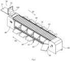
- the dual-layer linear sorter includes a delivery mechanism 10, a first feeding mechanism 20, a second feeding mechanism 30, a slewing mechanism 40 and a driving mechanism 50.
- the delivery mechanism 10 is ring-shaped and is configured to include an upper layer and a lower layer.
- the running direction of the upper layer is the first direction D1
- the running direction of the lower layer is the second direction D2
- the first direction D1 is from one end of the delivery mechanism 10 to the other end of the delivery mechanism 10
- the second direction D2 is opposite to the first direction D1.
- the first feeding mechanism 20 is close to the upper layer of the delivery mechanism 10 and is docked with one end of the delivery mechanism 10.
- the second feeding mechanism 30 is close to the lower layer of the delivery mechanism 10 and is docked with the other end of the delivery mechanism 10.
- the slewing mechanism 40 is connected to one end of the delivery mechanism 10.
- the driving mechanism 50 is connected to the other end of the delivery mechanism 10.
- the driving mechanism 50 can drive the delivery mechanism 10 to circulate in a loop between the driving mechanism 50 and the slewing mechanism 40, a part of the goods 100 can be delivered to the upper layer of the delivery mechanism 10 via the first feeding mechanism 20, and delivered and sorted along the first direction D1, another part of the goods 100 can be delivered to the lower layer of the delivery mechanism 10 via the second feeding mechanism 30, and delivered and sorted in the second direction D2.
- the dual-layer linear sorter of the present disclosure is designed with a left-middle-right structure for the delivery mechanism 10, the left and right structures are respectively combined with the slewing mechanism 40 and the driving mechanism 50, the middle structure is the delivery part, and is divided into an upper layer and a lower layer, which are respectively docked with the first feeding mechanism 20 and the second feeding mechanism 30, so that the upper and lower layers can simultaneously deliver the goods 100 to be sorted.
- the present disclosure realizes simultaneous delivering of the upper and lower layers, which doubles the sorting efficiency and improves the utilization rate of the sorter, it is especially suitable for sorting centers with narrow and long venues and large processing capacity requirements.
- the dual-layer linear sorter of the present disclosure can reduce its occupied space by half, thereby facilitating the miniaturization of the equipment and reducing the production cost.
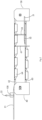
- the delivery mechanism 10 may include a plurality of delivery units 11 and a plurality of hinge parts 12, adjacent delivery units 11 are hinged through one hinge part 12 so that the delivery mechanism 10 is surrounded between the slewing mechanism 40 and the driving mechanism 50.
- the hinge part 12 may include a pair of mounting bases 121, a hinge shaft 122, a shaft sleeve 123 and an alignment portion 124, a mounting base 121 and a hinge shaft 122 are provided on one side of one of the two adjacent delivery units 11, the hinge shaft 122 is detachably connected between the pair of mounting bases 121, an alignment portion 124 is provided on a side of each mounting base 121 facing away from the hinge shaft 122, and one end of the alignment portion 124 protrudes from the delivery unit 11 along the axial direction of the hinge shaft 122; a shaft sleeve 123 is provided on one side of one of the two adjacent delivery units 11; the hinge shaft 122 is movably sleeved in the shaft sleeve 123, thereby enabling the two adjacent delivery units 11 to rotate relatively.
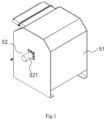
- the driving mechanism 50 is connected to the other end of the delivery mechanism 10, the driving mechanism 50 may include a driving housing 51, a motor 52 and a pair of first turntables 53, the motor 52 and the first turntables 53 are accommodated in the driving housing 51, and the driving shaft 521 of the motor 52 is connected to the centers of the first turntables 53.
- the outer periphery of the first turntable 53 is provided with a plurality of first grooves 531 that cooperate with the alignment portions 124, and the plurality of alignment portions 124 at the other end of the delivery mechanism 10 are respectively accommodated in the first grooves 531.
- the driving shaft 521 drives the first turntable 53 to rotate, and during the rotation of the first turntable 53, the first grooves 531 drive the alignment portions 124 that are aligned therewith to rotate synchronously, the aligning portion 124 enter the first grooves 531 aligned therewith one by one, thereby driving the delivery unit 11 to deliver.
- first grooves 531 can be provided on the outer periphery of the first turntable 53, the distance between two adjacent first grooves 531 is equal to the distance between two adjacent alignment portions 124. The number and distance of the first grooves 531 can be changed accordingly as needed.
- the slewing mechanism 40 is connected to one end of the delivery mechanism 10, the slewing mechanism 40 includes a slewing housing 41, a slewing shaft 42 and a second turntable 43, the second turntable 43 and the slewing shaft 42 are accommodated in the slewing housing 41, and the slewing shaft 42 is connected to the center of the second turntable 43, the outer periphery of the second turntable 43 is provided with a plurality of second grooves 431 that cooperate with alignment portions 124, the plurality of alignment portions 124 at one end of the delivery mechanism 10 are respectively accommodated in the second grooves 431 correspondingly.
- the delivery mechanism 10 is delivered under the action of the driving mechanism 50, during the movement of the delivery unit 11, the positioning portions 124 enter the second grooves 431 aligned therewith one by one, thereby driving the second turntables 43 to rotate. Where, as shown in FIG. 7 , there can be a pair of second turntables 43.
- the second turntable 43 is similar to the first turntable 53, and the alignment relationship and principle between the second groove 431 and the alignment portion 124 are similar to the alignment relationship and principle between the second groove 431 and the alignment portion 124 of the driving mechanism 50.
- the groove of the turntable is aligned with the alignment portion 124 of the transfer unit 11, so that the delivery mechanism moves smoothly.
- the motor 52 can have a variety of speeds to obtain a variety of sorting speeds of the sorter.
- the slewing housing 41 may include a vertical plate 411, and the vertical plate 411 covers the outside of the second turntable 43, at a position corresponding to the slewing shaft 42, a long hole 412 is opened on the vertical plate 411;
- the slewing mechanism 40 also includes an adjustment assembly, which includes a fixed plate 441, a movable plate 442 and an adjuster 443, the fixed plate 441 is fixed to the vertical plate 411, and the slewing shaft 42 and the movable plate 442 are connected by a bearing 444, the adjuster 443 connects the fixed plate 441 and the movable plate 442, and can drive the movable plate 442 to move in the first direction D1 or the second direction D2, so that the slewing shaft 42 moves within the length range of the long hole 412, thereby driving one end of the delivery mechanism to move in the first direction D1 or the second direction D2 relative to the other end of the delivery mechanism.
- the movable plate 442 is provided with a through hole H1 located at the center of the movable plate 442 and a long adjusting hole H2 located at the periphery of the movable plate 442, the bearing 444 and the end portion of the slewing shaft 42 are arranged in the through hole H1, the bolts 445 pass through the long adjusting hole H2 and against the vertical plate 411, the adjuster 443 passes through the fixed plate 441 and can move relative to the fixed plate 441, and one end of the adjuster 443 is fixed to the movable plate 442.
- the adjuster 443 and the fixed plate 441 may be screwed together, the relative position between the adjuster 443 and the fixed plate 441 can be changed by rotating the adjuster 443.
- the movable plate 442 By pulling the other end of the adjuster 443, the movable plate 442 can be driven to move, thereby driving the slewing shaft 42 to move back and forth, correspondingly, the second turntables 43 moves back and forth. Therefore, if there is a problem of slack in the delivery mechanism 10 after long-term use, the second turntables 43 can be pushed in a direction away from the driving mechanism 50, so that both the upper and lower layers of the delivery mechanism 10 are tensioned, so that the goods 100 can be delivered on the delivery mechanism 10 smoothly and quickly.
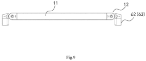
- the dual-layer linear sorter can also include a frame mechanism, the frame mechanism includes a supporting portion 61, an upper track 62, a lower track 63 and a sliding groove 64, the upper track 62 and the lower track 63 are supported by the supporting portion 61 and are used for the delivery mechanism 10 to run, the upper track 62 is provided on the upper layer of the delivery mechanism 10, and the lower track 63 is provided on the lower layer of the delivery mechanism 10, both ends of the upper track 62 and both ends of the lower track 63 are respectively connected to the slewing housing 41 and the driving housing 51, a plurality of sliding grooves 64 are provided on both sides of the upper track 62 and the lower track 63 for receiving the sorted goods 100.
- the first feeding mechanism 20 includes a first feeding section 21 and a first scanning unit 22, the first feeding section 21 is docked with the other end of the delivery mechanism 10 and extends along the extension direction of the upper track 62, a part of the first feeding section 21 is located on the slewing housing 41; the first scanning unit 22 is located on the first feeding section 21, and the first scanning unit 22 can be installed parallel to the running direction of the delivery mechanism 10.
- the second feeding mechanism 30 includes a second feeding section 31, a turning section 32 and a second scanning unit 33, one end of the second feeding section 31 extends beyond one side of the lower layer of the delivery mechanism 10, the turning section 32 is connected to the other end of the second feeding section 31 and extends to the upper side of the lower layer of the delivery mechanism 10 through the turning section 32; the second scanning unit 33 is located between the upper layer of the delivery mechanism 10 and the lower layer of the delivery mechanism 10.
- the second feeding mechanism 30 of this embodiment is designed as the following structure: the second feeding section 31 first forms an angle with the sorter, and then turns an angle through the turning section 32 to extend to the upper side of the lower layer of the delivery mechanism 10 and continue to extend along the delivering direction.
- the goods 100 are transported from the first feeding section 21 to the upper layer of the delivery mechanism 10, and the first scanning unit 22 located above scans the barcode information on the goods 100 and inquires the destination in the warehouse management system (WMS). According to the size of the delivery unit 11 and the number occupied, the sorter judges how many delivery units 11 are needed to unload the goods 100, when the delivery mechanism 10 runs to the sliding groove 64 of the designated destination, the delivery units 11 under the goods 100 acts to unload the goods 100 to the corresponding sliding groove 64.
- WMS warehouse management system
- the delivering principle of the lower layer of the delivery mechanism 10 is similar to the delivering principle of the upper layer of the delivery mechanism 10, except that the directions of the two are opposite, and the positions of the feeding mechanisms and the scanning units are different, so it is not repeated here.
- the dual-layer linear sorter of the present disclosure is designed with a left-middle-right structure for the delivery mechanism, the left and right structures are respectively combined with the slewing mechanism and the driving mechanism, the middle structure is the delivery part, and is divided into an upper layer and a lower layer, which are respectively docked with the first feeding mechanism and the second feeding mechanism, so that the upper and lower layers can simultaneously deliver the goods to be sorted.
- the present disclosure realizes simultaneous delivering of the upper and lower layers, which doubles the sorting efficiency and improves the utilization rate of the sorter, it is especially suitable for sorting centers with narrow and long venues and large processing capacity requirements.
- the dual-layer linear sorter of the present disclosure can reduce its occupied space by half, thereby facilitating the miniaturization of the equipment and reducing the production cost.
Landscapes
- Engineering & Computer Science (AREA)
- Mechanical Engineering (AREA)
- Discharge Of Articles From Conveyors (AREA)
- Branching, Merging, And Special Transfer Between Conveyors (AREA)
Claims (9)
- Zweilagiger Linearsortierer, umfassend:einen Fördermechanismus (10), der ringförmig ausgebildet und dazu ausgelegt ist, eine obere Lage und eine untere Lage zu umfassen, wobei eine Laufrichtung der oberen Lage eine erste Richtung (D1) ist und eine Laufrichtung der unteren Lage eine zweite Richtung (D2) ist, wobei die erste Richtung (D1) von dem einen Ende des Fördermechanismus (10) zum anderen Ende des Fördermechanismus (10) verläuft und die zweite Richtung (D2) der ersten Richtung (D1) entgegengesetzt ist;wobei der Fördermechanismus (10) eine Vielzahl von Fördereinheiten (11) und eine Vielzahl von Gelenkteilen (12) umfasst, wobei benachbarte Fördereinheiten (11) durch ein Gelenkteil (12) gelenkig verbunden sind;wobei das Gelenkteil (12) ein Paar von Lagersockeln (121), eine Gelenkwelle (122), eine Wellenhülse (123) und einen Ausrichtungsabschnitt (124) umfasst, wobei ein Lagersockel (121) und eine Gelenkwelle (122) auf einer Seite einer der beiden benachbarten Fördereinheiten (11) vorgesehen sind, die Gelenkwelle (122) lösbar zwischen dem Paar von Lagersockeln (121) vorgesehen ist, der Ausrichtungsabschnitt (124) auf einer von der Gelenkwelle (122) abgewandten Seite jedes Lagersockels (121) vorgesehen ist und ein Ende des Ausrichtungsabschnitts (124) von den Fördereinheiten (11) entlang einer axialen Richtung der Gelenkwelle (122) vorsteht; wobei die Wellenhülse (123) an einer Seite einer der beiden benachbarten Fördereinheiten (11) vorgesehen ist; wobei die Gelenkwelle (122) beweglich in der Wellenhülse (123) gelagert ist;einen ersten Zuführmechanismus (20), der sich in der Nähe der oberen Lage des Fördermechanismus (10) befindet und an das eine Ende des Fördermechanismus (10) angedockt ist;einen zweiten Zuführmechanismus (30), der sich in der Nähe der unteren Lage des Fördermechanismus (10) befindet und an das andere Ende des Fördermechanismus (10) angedockt ist;einen Schwenkmechanismus (40), der mit dem einen Ende des Fördermechanismus (10) verbunden ist; undeinen Antriebsmechanismus (50), der mit dem anderen Ende des Fördermechanismus (10) verbunden ist;wobei der Antriebsmechanismus (50) dazu ausgelegt ist, den Fördermechanismus (10) so anzutreiben, dass er in einer Schleife zwischen dem Antriebsmechanismus (50) und dem Schwenkmechanismus (40) zirkuliert, wobei ein Teil der Güter (100) über den ersten Zuführmechanismus (20) an die obere Lage des Fördermechanismus (10) abgegeben wird und entlang der ersten Richtung (D1) gefördert und sortiert wird, wobei ein anderer Teil der Güter (100) über den zweiten Zuführmechanismus (30) an die untere Lage des Fördermechanismus (10) abgegeben wird und in der zweiten Richtung (D2) gefördert und sortiert wird.
- Zweilagiger Linearsortierer nach Anspruch 1, wobei der Antriebsmechanismus (50) mit dem anderen Ende des Fördermechanismus (10) verbunden ist, der Antriebsmechanismus (50) ein Antriebsgehäuse (51), einen Motor (52) und ein Paar erster Drehteller (53) umfasst, wobei der Motor (52) und die ersten Drehteller (53) in dem Antriebsgehäuse (51) aufgenommen sind und eine Antriebswelle (521) des Motors (52) mit den Zentren der ersten Drehteller (53) verbunden ist, wobei ein Außenumfang jedes der ersten Drehteller (53) mit einer Vielzahl von ersten Nuten (531) versehen ist, die mit Ausrichtungsabschnitten (124) zusammenwirken, und eine Vielzahl von Ausrichtungsabschnitten (124) am anderen Ende des Fördermechanismus (10) in den jeweiligen ersten Nuten (531) aufgenommen sind, wobei während eines Betriebs des Motors (52) die Antriebswelle (521) die ersten Drehteller (53) zum Drehen antreibt, wodurch die Fördereinheiten (11) zum Fördern angetrieben werden.
- Zweilagiger Linearsortierer nach Anspruch 2, wobei eine Vielzahl von gleichmäßig beabstandeten ersten Nuten (531) am Außenumfang jedes der ersten Drehteller (53) vorgesehen sind, wobei ein Abstand zwischen zwei benachbarten ersten Nuten (531) gleich einem Abstand zwischen zwei benachbarten Ausrichtungsabschnitten (124) ist.
- Zweilagiger Linearsortierer nach Anspruch 2, wobei der Schwenkmechanismus (40) mit einem Ende des Fördermechanismus (10) verbunden ist, der Schwenkmechanismus (40) ein Schwenkgehäuse (41), eine Schwenkwelle (42) und einen zweiten Drehteller (43) umfasst, wobei der zweite Drehteller (43) und die Schwenkwelle (42) in dem Schwenkgehäuse (41) aufgenommen sind und die Schwenkwelle (42) mit einem Zentrum des zweiten Drehtellers (43) verbunden ist, wobei ein Außenumfang des zweiten Drehtellers (43) mit einer Vielzahl von zweiten Nuten (431) versehen ist, die mit Ausrichtungsabschnitten (124) zusammenwirken, wobei eine Vielzahl von Ausrichtungsabschnitten (124) an einem Ende des Fördermechanismus (10) entsprechend in den jeweiligen zweiten Nuten (431) aufgenommen sind, wobei während eines Förderprozesses des Fördermechanismus (10) die Fördereinheiten (11) den zweiten Drehteller (43) zum Drehen antreiben.
- Zweilagiger Linearsortierer nach Anspruch 4, wobei das Schwenkgehäuse (41) eine vertikale Platte (411) umfasst und die vertikale Platte (411) die Außenseite des zweiten Drehtellers (43) abdeckt, wobei an einer der Schwenkwelle (42) entsprechenden Position ein Langloch (412) in der vertikalen Platte (411) eingebracht ist; wobei der Schwenkmechanismus (40) auch eine Einstellanordnung umfasst, wobei die Einstellanordnung eine feste Platte (441), eine bewegliche Platte (442) und eine Einstelleinrichtung (443) umfasst, wobei die feste Platte (441) an die vertikale Platte (411) befestigt ist und die Schwenkwelle (42) und die bewegliche Platte (442) über ein Lager (444) verbunden sind, wobei die Einstelleinrichtung (443) die feste Platte (441) und die bewegliche Platte (442) verbindet und die bewegliche Platte (442) so antreibt, dass sie sich in der ersten Richtung (D1) oder der zweiten Richtung (D2) bewegt, so dass sich die Schwenkwelle (42) innerhalb eines Längenbereichs des Langlochs (412) bewegt, wodurch das eine Ende des Fördermechanismus (10) so angetrieben wird, dass es sich in der ersten Richtung (D1) oder der zweiten Richtung (D2) relativ zum anderen Ende des Fördermechanismus (10) bewegt.
- Zweilagiger Linearsortierer nach Anspruch 5, wobei die bewegliche Platte (442) mit einem Durchgangsloch (H1), das sich im Zentrum der beweglichen Platte (442) befindet, und einem Einstelllangloch (H2), das sich an einem Umfang der beweglichen Platte (442) befindet, versehen ist, wobei das Lager (444) und ein Endabschnitt der Schwenkwelle (42) im Durchgangsloch (H1) angeordnet sind, wobei durch das Einstelllangloch (H2) Bolzen (445) hindurchgeführt sind und an der vertikalen Platte (411) anliegen, wobei die Einstelleinrichtung (443) durch die feste Platte (441) hindurchgeführt und dazu ausgelegt ist, sich relativ zur festen Platte (441) zu bewegen, und wobei das eine Ende der Einstelleinrichtung (443) an die bewegliche Platte (442) befestigt ist, wobei durch Ziehen an dem anderen Ende der Einstelleinrichtung (443) die bewegliche Platte (442) zur Bewegung angetrieben wird.
- Zweilagiger Linearsortierer nach Anspruch 4, ferner umfassend:
einen Rahmenmechanismus, der einen Stützabschnitt (61), eine obere Schiene (62), eine untere Schiene (63) und eine Gleitnut (64) umfasst, wobei die obere Schiene (62) und die untere Schiene (63) von einem Stützabschnitt (61) abgestützt werden und für den Lauf des Fördermechanismus (10) Anwendung finden, wobei die obere Schiene (62) an der oberen Lage des Fördermechanismus (10) vorgesehen ist und die untere Schiene (63) an der unteren Lage des Fördermechanismus (10) vorgesehen ist, wobei beide Enden der oberen Schiene (62) und beide Enden der unteren Schiene (63) jeweils mit dem Schwenkgehäuse (41) bzw. dem Antriebsgehäuse (51) verbunden sind, wobei eine Vielzahl von Gleitnuten (64) auf beiden Seiten der oberen Schiene (62) und der unteren Schiene (63) zur Aufnahme von sortierten Gütern (100) vorgesehen ist. - Zweilagiger Linearsortierer nach Anspruch 7, wobei der erste Zuführmechanismus (20) einen ersten Zuführabschnitt (21) und eine erste Abtasteinheit (22) umfasst, wobei der erste Zuführabschnitt (21) an das andere Ende des Fördermechanismus (10) angedockt ist und sich entlang einer Erstreckungsrichtung der oberen Schiene (62) erstreckt, wobei ein Teil des ersten Zuführabschnitts (21) sich an dem Schwenkgehäuse (41) befindet; wobei die erste Abtasteinheit (22) sich an dem ersten Zuführabschnitt (21) befindet.
- Zweilagiger Linearsortierer nach Anspruch 7, wobei der zweite Zuführmechanismus (30) einen zweiten Zuführabschnitt (31), einen Wendeabschnitt (32) und eine zweite Abtasteinheit (33) umfasst, wobei das eine Ende des zweiten Zuführabschnitts (31) sich über eine Seite der unteren Lage des Fördermechanismus (10) hinaus erstreckt, der Wendeabschnitt (32) mit dem anderen Ende des zweiten Zuführabschnitts (31) verbunden ist und sich durch den Wendeabschnitt (32) hindurch zu einer oberen Seite der unteren Lage des Fördermechanismus (10) erstreckt; wobei die zweite Abtasteinheit (33) sich zwischen der oberen Lage des Fördermechanismus (10) und der unteren Lage des Fördermechanismus (10) befindet.
Applications Claiming Priority (2)
| Application Number | Priority Date | Filing Date | Title |
|---|---|---|---|
| CN201910037022.8A CN111434593A (zh) | 2019-01-15 | 2019-01-15 | 一种双层直线式分拣机 |
| PCT/CN2020/070128 WO2020147592A1 (zh) | 2019-01-15 | 2020-01-02 | 双层直线式分拣机 |
Publications (4)
| Publication Number | Publication Date |
|---|---|
| EP3912935A1 EP3912935A1 (de) | 2021-11-24 |
| EP3912935A4 EP3912935A4 (de) | 2022-11-30 |
| EP3912935C0 EP3912935C0 (de) | 2025-04-23 |
| EP3912935B1 true EP3912935B1 (de) | 2025-04-23 |
Family
ID=71580843
Family Applications (1)
| Application Number | Title | Priority Date | Filing Date |
|---|---|---|---|
| EP20741893.0A Active EP3912935B1 (de) | 2019-01-15 | 2020-01-02 | Zweischichtiger linearer sortierer |
Country Status (7)
| Country | Link |
|---|---|
| US (1) | US11365066B2 (de) |
| EP (1) | EP3912935B1 (de) |
| JP (1) | JP7325513B2 (de) |
| KR (1) | KR102534415B1 (de) |
| CN (1) | CN111434593A (de) |
| PL (1) | PL3912935T3 (de) |
| WO (1) | WO2020147592A1 (de) |
Families Citing this family (12)
| Publication number | Priority date | Publication date | Assignee | Title |
|---|---|---|---|---|
| EP4259555A2 (de) * | 2020-12-10 | 2023-10-18 | Interroll Holding AG | Ausschleusvorrichtung |
| CN114633995A (zh) * | 2020-12-16 | 2022-06-17 | 杭州旭辉快递智能设备有限公司 | 多层直线循环输送机及其双面小车 |
| CN113734712B (zh) * | 2021-09-02 | 2025-01-14 | 广汽丰田发动机有限公司 | 一种用于曲轴多机种加工的双层上料输送装置 |
| CN114932093B (zh) * | 2022-05-31 | 2023-06-16 | 瑞浦兰钧能源股份有限公司 | 一种不良电池组盘设备及电池生产线 |
| CN115090538A (zh) * | 2022-06-20 | 2022-09-23 | 东莞市山藤智能科技有限公司 | 一种多区域分拣装置 |
| CN115214051A (zh) * | 2022-07-19 | 2022-10-21 | 李士新 | 把手供应装置 |
| CN115973680A (zh) * | 2022-12-09 | 2023-04-18 | 上海健麾信息技术股份有限公司 | 一种分拣机构 |
| EP4455061A1 (de) * | 2023-03-31 | 2024-10-30 | Interroll Holding AG | Transfervorrichtung |
| CN116873530B (zh) * | 2023-07-31 | 2024-02-23 | 浙江应杰科技有限公司 | 一种双层交叉带分拣设备及使用方法 |
| CN116729966B (zh) * | 2023-08-03 | 2024-01-23 | 中国邮政集团有限公司淄博市博山区分公司 | 一种智能云仓物流分拣皮带输送设备 |
| CN117228292A (zh) * | 2023-08-29 | 2023-12-15 | 广东贝导智能科技有限公司 | 一种电芯分选装置 |
| CN117485876B (zh) * | 2023-12-15 | 2025-12-05 | 芜湖驿龙科技有限公司 | 分拣运输线和分拣运输系统 |
Family Cites Families (22)
| Publication number | Priority date | Publication date | Assignee | Title |
|---|---|---|---|---|
| JPS6132892Y2 (de) * | 1981-02-26 | 1986-09-25 | ||
| DK155207C (da) * | 1985-08-26 | 1989-07-10 | Int Transport Syst Its | Sorteringsmaskine, isaer til smaapakker |
| US5284252A (en) * | 1991-11-13 | 1994-02-08 | United Parcel Service Of America, Inc. | Automatic rotary sorter |
| US5433311A (en) * | 1993-11-17 | 1995-07-18 | United Parcel Service Of America, Inc. | Dual level tilting tray package sorting apparatus |
| US5901830A (en) * | 1997-01-22 | 1999-05-11 | Electrocom Automation, L.P. | Bi-directional belt sorter |
| KR100368228B1 (ko) * | 1998-12-03 | 2003-03-17 | 주식회사 포스코 | 곡선부에서의 운반물 이송용 콘베이어 |
| US6619465B1 (en) | 1999-03-31 | 2003-09-16 | Gebhardt Fördertechnik GmbH | Points for a feeding system, especially a gravity roller table |
| DE19957841A1 (de) * | 1999-12-01 | 2001-06-07 | Applimont Gmbh Software | Vorrichtung zum versandfertigen Sortieren von Waren |
| WO2004083084A1 (en) * | 2003-03-17 | 2004-09-30 | Crisplant A/S | A space adjustable conveyor with article carriers |
| AT506638B1 (de) | 2008-04-03 | 2010-05-15 | Salomon Automation Gmbh | Kommisionieranlage und verfahren zum kommissionieren |
| JP5688737B2 (ja) | 2011-02-18 | 2015-03-25 | スターテクノ株式会社 | キャタピラー型チェーンコンベヤ |
| CN103787030B (zh) * | 2014-01-17 | 2016-02-10 | 常州大学 | 一种基于机械手施行的自动收碗机构 |
| US9409716B2 (en) * | 2014-06-13 | 2016-08-09 | Bastian Solutions, Llc | Cross belt slat sorter |
| CN205293999U (zh) * | 2016-01-20 | 2016-06-08 | 宁波致富宝生物科技有限公司 | 一种有机肥输送带松紧调节装置 |
| CN205526236U (zh) * | 2016-03-01 | 2016-08-31 | 郑州市顺意科技有限公司 | 自动上料装置 |
| CN108792381B (zh) * | 2017-05-05 | 2024-05-17 | 北京京东乾石科技有限公司 | 分拣小车 |
| CN106956887B (zh) | 2017-05-05 | 2022-09-30 | 北京京东乾石科技有限公司 | 立式分拣机 |
| CN107020247B (zh) | 2017-06-01 | 2023-01-17 | 辽宁科技大学 | 全自动快递件分拣系统 |
| CN208135406U (zh) | 2018-01-19 | 2018-11-23 | 标杩自动化设备(东莞)有限公司 | 一种双层环形交叉带自动分拣线 |
| CN208104707U (zh) * | 2018-04-02 | 2018-11-16 | 江苏锦竹工业用布有限公司 | 一种自动压布条机的分边装置 |
| CN109516165A (zh) * | 2018-12-06 | 2019-03-26 | 沈志伟 | 一种直线型上下行程自动分拣单列装置 |
| CN209701663U (zh) * | 2019-01-15 | 2019-11-29 | 北京京东尚科信息技术有限公司 | 一种双层直线式分拣机 |
-
2019
- 2019-01-15 CN CN201910037022.8A patent/CN111434593A/zh active Pending
-
2020
- 2020-01-02 JP JP2021535209A patent/JP7325513B2/ja active Active
- 2020-01-02 PL PL20741893.0T patent/PL3912935T3/pl unknown
- 2020-01-02 KR KR1020217019221A patent/KR102534415B1/ko active Active
- 2020-01-02 EP EP20741893.0A patent/EP3912935B1/de active Active
- 2020-01-02 US US17/414,557 patent/US11365066B2/en active Active
- 2020-01-02 WO PCT/CN2020/070128 patent/WO2020147592A1/zh not_active Ceased
Also Published As
| Publication number | Publication date |
|---|---|
| US20220009724A1 (en) | 2022-01-13 |
| JP2022514583A (ja) | 2022-02-14 |
| PL3912935T3 (pl) | 2025-08-04 |
| EP3912935C0 (de) | 2025-04-23 |
| KR20210093329A (ko) | 2021-07-27 |
| EP3912935A1 (de) | 2021-11-24 |
| US11365066B2 (en) | 2022-06-21 |
| KR102534415B1 (ko) | 2023-05-18 |
| CN111434593A (zh) | 2020-07-21 |
| EP3912935A4 (de) | 2022-11-30 |
| WO2020147592A1 (zh) | 2020-07-23 |
| JP7325513B2 (ja) | 2023-08-14 |
Similar Documents
| Publication | Publication Date | Title |
|---|---|---|
| EP3912935B1 (de) | Zweischichtiger linearer sortierer | |
| US10252827B2 (en) | Packaging system and method utilizing intelligent conveyor systems | |
| US6253901B1 (en) | Linked conveyor (sorter) for the sorting of small cargo units | |
| JP7252368B2 (ja) | 仕分け設備 | |
| JP2003506289A (ja) | 一貫搬送キャリヤ及びディレクターを有する搬送装置 | |
| CN107323572B (zh) | 分拣型自动导引运输车 | |
| JP3228266B2 (ja) | パレット搬送方向変更装置 | |
| CN217888713U (zh) | 一种物流仓储自动分拣系统设备 | |
| US7475520B2 (en) | Tray positioning device for stacking of product | |
| CN111908123B (zh) | 储料器输送机 | |
| JPH06239451A (ja) | 4方向型パレット搬送設備 | |
| KR102425593B1 (ko) | 수직형 물품 분류 장치 | |
| JP2020083481A (ja) | 多種多様物品仕分装置 | |
| CN210125560U (zh) | 分拣设备 | |
| CN220536617U (zh) | 一种后勤仓储物流输送装置 | |
| JP2004010304A (ja) | 垂直循環型トレイ式仕分け装置 | |
| CN209701663U (zh) | 一种双层直线式分拣机 | |
| JP6750510B2 (ja) | 搬送装置 | |
| CN212659136U (zh) | 用于无接触投递的开合装置及无接触自动售卖设备 | |
| JP2003246443A (ja) | 搬送装置、並びに、倉庫装置 | |
| US8774961B2 (en) | Automatic delivery system for continuous batch order processing | |
| KR100426003B1 (ko) | 타이어 비드의 이송 공급장치 | |
| JP2017057077A (ja) | 仕分け装置、およびこれを備えた仕分けシステム | |
| KR102830678B1 (ko) | 휠소터 장치 및 이를 포함하는 물류제어시스템 | |
| JP2021120315A (ja) | 搬送装置および自動倉庫システム |
Legal Events
| Date | Code | Title | Description |
|---|---|---|---|
| STAA | Information on the status of an ep patent application or granted ep patent |
Free format text: STATUS: THE INTERNATIONAL PUBLICATION HAS BEEN MADE |
|
| PUAI | Public reference made under article 153(3) epc to a published international application that has entered the european phase |
Free format text: ORIGINAL CODE: 0009012 |
|
| STAA | Information on the status of an ep patent application or granted ep patent |
Free format text: STATUS: REQUEST FOR EXAMINATION WAS MADE |
|
| 17P | Request for examination filed |
Effective date: 20210624 |
|
| AK | Designated contracting states |
Kind code of ref document: A1 Designated state(s): AL AT BE BG CH CY CZ DE DK EE ES FI FR GB GR HR HU IE IS IT LI LT LU LV MC MK MT NL NO PL PT RO RS SE SI SK SM TR |
|
| DAV | Request for validation of the european patent (deleted) | ||
| DAX | Request for extension of the european patent (deleted) | ||
| A4 | Supplementary search report drawn up and despatched |
Effective date: 20221028 |
|
| RIC1 | Information provided on ipc code assigned before grant |
Ipc: B07C 3/06 20060101ALI20221024BHEP Ipc: B65G 47/96 20060101ALI20221024BHEP Ipc: B65G 23/44 20060101ALI20221024BHEP Ipc: B65G 23/22 20060101ALI20221024BHEP Ipc: B65G 21/22 20060101ALI20221024BHEP Ipc: B65G 17/06 20060101ALI20221024BHEP Ipc: B65G 17/34 20060101ALI20221024BHEP Ipc: B65G 15/28 20060101ALI20221024BHEP Ipc: B65G 1/04 20060101ALI20221024BHEP Ipc: B65G 47/44 20060101ALI20221024BHEP Ipc: B65G 47/04 20060101AFI20221024BHEP |
|
| GRAP | Despatch of communication of intention to grant a patent |
Free format text: ORIGINAL CODE: EPIDOSNIGR1 |
|
| STAA | Information on the status of an ep patent application or granted ep patent |
Free format text: STATUS: GRANT OF PATENT IS INTENDED |
|
| INTG | Intention to grant announced |
Effective date: 20241209 |
|
| GRAS | Grant fee paid |
Free format text: ORIGINAL CODE: EPIDOSNIGR3 |
|
| GRAA | (expected) grant |
Free format text: ORIGINAL CODE: 0009210 |
|
| STAA | Information on the status of an ep patent application or granted ep patent |
Free format text: STATUS: THE PATENT HAS BEEN GRANTED |
|
| AK | Designated contracting states |
Kind code of ref document: B1 Designated state(s): AL AT BE BG CH CY CZ DE DK EE ES FI FR GB GR HR HU IE IS IT LI LT LU LV MC MK MT NL NO PL PT RO RS SE SI SK SM TR |
|
| REG | Reference to a national code |
Ref country code: GB Ref legal event code: FG4D |
|
| REG | Reference to a national code |
Ref country code: CH Ref legal event code: EP |
|
| REG | Reference to a national code |
Ref country code: DE Ref legal event code: R096 Ref document number: 602020049952 Country of ref document: DE |
|
| REG | Reference to a national code |
Ref country code: IE Ref legal event code: FG4D |
|
| U01 | Request for unitary effect filed |
Effective date: 20250516 |
|
| U07 | Unitary effect registered |
Designated state(s): AT BE BG DE DK EE FI FR IT LT LU LV MT NL PT RO SE SI Effective date: 20250522 |
|
| PG25 | Lapsed in a contracting state [announced via postgrant information from national office to epo] |
Ref country code: ES Free format text: LAPSE BECAUSE OF FAILURE TO SUBMIT A TRANSLATION OF THE DESCRIPTION OR TO PAY THE FEE WITHIN THE PRESCRIBED TIME-LIMIT Effective date: 20250423 |
|
| PG25 | Lapsed in a contracting state [announced via postgrant information from national office to epo] |
Ref country code: NO Free format text: LAPSE BECAUSE OF FAILURE TO SUBMIT A TRANSLATION OF THE DESCRIPTION OR TO PAY THE FEE WITHIN THE PRESCRIBED TIME-LIMIT Effective date: 20250723 Ref country code: GR Free format text: LAPSE BECAUSE OF FAILURE TO SUBMIT A TRANSLATION OF THE DESCRIPTION OR TO PAY THE FEE WITHIN THE PRESCRIBED TIME-LIMIT Effective date: 20250724 |
|
| PG25 | Lapsed in a contracting state [announced via postgrant information from national office to epo] |
Ref country code: HR Free format text: LAPSE BECAUSE OF FAILURE TO SUBMIT A TRANSLATION OF THE DESCRIPTION OR TO PAY THE FEE WITHIN THE PRESCRIBED TIME-LIMIT Effective date: 20250423 |
|
| PG25 | Lapsed in a contracting state [announced via postgrant information from national office to epo] |
Ref country code: RS Free format text: LAPSE BECAUSE OF FAILURE TO SUBMIT A TRANSLATION OF THE DESCRIPTION OR TO PAY THE FEE WITHIN THE PRESCRIBED TIME-LIMIT Effective date: 20250723 |
|
| PG25 | Lapsed in a contracting state [announced via postgrant information from national office to epo] |
Ref country code: IS Free format text: LAPSE BECAUSE OF FAILURE TO SUBMIT A TRANSLATION OF THE DESCRIPTION OR TO PAY THE FEE WITHIN THE PRESCRIBED TIME-LIMIT Effective date: 20250823 |
|
| PGFP | Annual fee paid to national office [announced via postgrant information from national office to epo] |
Ref country code: GB Payment date: 20251205 Year of fee payment: 7 |
|
| PG25 | Lapsed in a contracting state [announced via postgrant information from national office to epo] |
Ref country code: SM Free format text: LAPSE BECAUSE OF FAILURE TO SUBMIT A TRANSLATION OF THE DESCRIPTION OR TO PAY THE FEE WITHIN THE PRESCRIBED TIME-LIMIT Effective date: 20250423 |
|
| U20 | Renewal fee for the european patent with unitary effect paid |
Year of fee payment: 7 Effective date: 20251209 |
|
| PG25 | Lapsed in a contracting state [announced via postgrant information from national office to epo] |
Ref country code: CZ Free format text: LAPSE BECAUSE OF FAILURE TO SUBMIT A TRANSLATION OF THE DESCRIPTION OR TO PAY THE FEE WITHIN THE PRESCRIBED TIME-LIMIT Effective date: 20250423 |
|
| PGFP | Annual fee paid to national office [announced via postgrant information from national office to epo] |
Ref country code: PL Payment date: 20251209 Year of fee payment: 7 |
|
| PG25 | Lapsed in a contracting state [announced via postgrant information from national office to epo] |
Ref country code: SK Free format text: LAPSE BECAUSE OF FAILURE TO SUBMIT A TRANSLATION OF THE DESCRIPTION OR TO PAY THE FEE WITHIN THE PRESCRIBED TIME-LIMIT Effective date: 20250423 |