EP3912918A1 - Verpackungsvorrichtung für kleinstückgüter und verfahren zum herstellen eines mehrere blisterbeutel umfassenden blisterschlauches - Google Patents
Verpackungsvorrichtung für kleinstückgüter und verfahren zum herstellen eines mehrere blisterbeutel umfassenden blisterschlauches Download PDFInfo
- Publication number
- EP3912918A1 EP3912918A1 EP20175582.4A EP20175582A EP3912918A1 EP 3912918 A1 EP3912918 A1 EP 3912918A1 EP 20175582 A EP20175582 A EP 20175582A EP 3912918 A1 EP3912918 A1 EP 3912918A1
- Authority
- EP
- European Patent Office
- Prior art keywords
- packaging material
- joining
- material web
- area
- packaging
- Prior art date
- Legal status (The legal status is an assumption and is not a legal conclusion. Google has not performed a legal analysis and makes no representation as to the accuracy of the status listed.)
- Granted
Links
Images



Classifications
-
- B—PERFORMING OPERATIONS; TRANSPORTING
- B65—CONVEYING; PACKING; STORING; HANDLING THIN OR FILAMENTARY MATERIAL
- B65B—MACHINES, APPARATUS OR DEVICES FOR, OR METHODS OF, PACKAGING ARTICLES OR MATERIALS; UNPACKING
- B65B9/00—Enclosing successive articles, or quantities of material, e.g. liquids or semiliquids, in flat, folded, or tubular webs of flexible sheet material; Subdividing filled flexible tubes to form packages
- B65B9/10—Enclosing successive articles, or quantities of material, in preformed tubular webs, or in webs formed into tubes around filling nozzles, e.g. extruded tubular webs
- B65B9/20—Enclosing successive articles, or quantities of material, in preformed tubular webs, or in webs formed into tubes around filling nozzles, e.g. extruded tubular webs the webs being formed into tubes in situ around the filling nozzles
- B65B9/2035—Tube guiding means
-
- B—PERFORMING OPERATIONS; TRANSPORTING
- B29—WORKING OF PLASTICS; WORKING OF SUBSTANCES IN A PLASTIC STATE IN GENERAL
- B29C—SHAPING OR JOINING OF PLASTICS; SHAPING OF MATERIAL IN A PLASTIC STATE, NOT OTHERWISE PROVIDED FOR; AFTER-TREATMENT OF THE SHAPED PRODUCTS, e.g. REPAIRING
- B29C65/00—Joining or sealing of preformed parts, e.g. welding of plastics materials; Apparatus therefor
- B29C65/02—Joining or sealing of preformed parts, e.g. welding of plastics materials; Apparatus therefor by heating, with or without pressure
-
- B—PERFORMING OPERATIONS; TRANSPORTING
- B29—WORKING OF PLASTICS; WORKING OF SUBSTANCES IN A PLASTIC STATE IN GENERAL
- B29C—SHAPING OR JOINING OF PLASTICS; SHAPING OF MATERIAL IN A PLASTIC STATE, NOT OTHERWISE PROVIDED FOR; AFTER-TREATMENT OF THE SHAPED PRODUCTS, e.g. REPAIRING
- B29C65/00—Joining or sealing of preformed parts, e.g. welding of plastics materials; Apparatus therefor
- B29C65/02—Joining or sealing of preformed parts, e.g. welding of plastics materials; Apparatus therefor by heating, with or without pressure
- B29C65/18—Joining or sealing of preformed parts, e.g. welding of plastics materials; Apparatus therefor by heating, with or without pressure using heated tools
-
- B—PERFORMING OPERATIONS; TRANSPORTING
- B29—WORKING OF PLASTICS; WORKING OF SUBSTANCES IN A PLASTIC STATE IN GENERAL
- B29C—SHAPING OR JOINING OF PLASTICS; SHAPING OF MATERIAL IN A PLASTIC STATE, NOT OTHERWISE PROVIDED FOR; AFTER-TREATMENT OF THE SHAPED PRODUCTS, e.g. REPAIRING
- B29C65/00—Joining or sealing of preformed parts, e.g. welding of plastics materials; Apparatus therefor
- B29C65/74—Joining or sealing of preformed parts, e.g. welding of plastics materials; Apparatus therefor by welding and severing, or by joining and severing, the severing being performed in the area to be joined, next to the area to be joined, in the joint area or next to the joint area
- B29C65/745—Joining or sealing of preformed parts, e.g. welding of plastics materials; Apparatus therefor by welding and severing, or by joining and severing, the severing being performed in the area to be joined, next to the area to be joined, in the joint area or next to the joint area using a single unit having both a severing tool and a welding tool
- B29C65/7451—Joining or sealing of preformed parts, e.g. welding of plastics materials; Apparatus therefor by welding and severing, or by joining and severing, the severing being performed in the area to be joined, next to the area to be joined, in the joint area or next to the joint area using a single unit having both a severing tool and a welding tool the severing tool and the welding tool being movable with respect to one-another
-
- B—PERFORMING OPERATIONS; TRANSPORTING
- B29—WORKING OF PLASTICS; WORKING OF SUBSTANCES IN A PLASTIC STATE IN GENERAL
- B29C—SHAPING OR JOINING OF PLASTICS; SHAPING OF MATERIAL IN A PLASTIC STATE, NOT OTHERWISE PROVIDED FOR; AFTER-TREATMENT OF THE SHAPED PRODUCTS, e.g. REPAIRING
- B29C65/00—Joining or sealing of preformed parts, e.g. welding of plastics materials; Apparatus therefor
- B29C65/78—Means for handling the parts to be joined, e.g. for making containers or hollow articles, e.g. means for handling sheets, plates, web-like materials, tubular articles, hollow articles or elements to be joined therewith; Means for discharging the joined articles from the joining apparatus
- B29C65/7858—Means for handling the parts to be joined, e.g. for making containers or hollow articles, e.g. means for handling sheets, plates, web-like materials, tubular articles, hollow articles or elements to be joined therewith; Means for discharging the joined articles from the joining apparatus characterised by the feeding movement of the parts to be joined
- B29C65/7861—In-line machines, i.e. feeding, joining and discharging are in one production line
- B29C65/787—In-line machines, i.e. feeding, joining and discharging are in one production line using conveyor belts or conveyor chains
- B29C65/7873—In-line machines, i.e. feeding, joining and discharging are in one production line using conveyor belts or conveyor chains using cooperating conveyor belts or cooperating conveyor chains
-
- B—PERFORMING OPERATIONS; TRANSPORTING
- B29—WORKING OF PLASTICS; WORKING OF SUBSTANCES IN A PLASTIC STATE IN GENERAL
- B29C—SHAPING OR JOINING OF PLASTICS; SHAPING OF MATERIAL IN A PLASTIC STATE, NOT OTHERWISE PROVIDED FOR; AFTER-TREATMENT OF THE SHAPED PRODUCTS, e.g. REPAIRING
- B29C66/00—General aspects of processes or apparatus for joining preformed parts
- B29C66/01—General aspects dealing with the joint area or with the area to be joined
- B29C66/05—Particular design of joint configurations
- B29C66/10—Particular design of joint configurations particular design of the joint cross-sections
- B29C66/11—Joint cross-sections comprising a single joint-segment, i.e. one of the parts to be joined comprising a single joint-segment in the joint cross-section
- B29C66/112—Single lapped joints
- B29C66/1122—Single lap to lap joints, i.e. overlap joints
-
- B—PERFORMING OPERATIONS; TRANSPORTING
- B29—WORKING OF PLASTICS; WORKING OF SUBSTANCES IN A PLASTIC STATE IN GENERAL
- B29C—SHAPING OR JOINING OF PLASTICS; SHAPING OF MATERIAL IN A PLASTIC STATE, NOT OTHERWISE PROVIDED FOR; AFTER-TREATMENT OF THE SHAPED PRODUCTS, e.g. REPAIRING
- B29C66/00—General aspects of processes or apparatus for joining preformed parts
- B29C66/01—General aspects dealing with the joint area or with the area to be joined
- B29C66/05—Particular design of joint configurations
- B29C66/10—Particular design of joint configurations particular design of the joint cross-sections
- B29C66/13—Single flanged joints; Fin-type joints; Single hem joints; Edge joints; Interpenetrating fingered joints; Other specific particular designs of joint cross-sections not provided for in groups B29C66/11 - B29C66/12
- B29C66/133—Fin-type joints, the parts to be joined being flexible
-
- B—PERFORMING OPERATIONS; TRANSPORTING
- B29—WORKING OF PLASTICS; WORKING OF SUBSTANCES IN A PLASTIC STATE IN GENERAL
- B29C—SHAPING OR JOINING OF PLASTICS; SHAPING OF MATERIAL IN A PLASTIC STATE, NOT OTHERWISE PROVIDED FOR; AFTER-TREATMENT OF THE SHAPED PRODUCTS, e.g. REPAIRING
- B29C66/00—General aspects of processes or apparatus for joining preformed parts
- B29C66/01—General aspects dealing with the joint area or with the area to be joined
- B29C66/05—Particular design of joint configurations
- B29C66/306—Applying a mark during joining
-
- B—PERFORMING OPERATIONS; TRANSPORTING
- B29—WORKING OF PLASTICS; WORKING OF SUBSTANCES IN A PLASTIC STATE IN GENERAL
- B29C—SHAPING OR JOINING OF PLASTICS; SHAPING OF MATERIAL IN A PLASTIC STATE, NOT OTHERWISE PROVIDED FOR; AFTER-TREATMENT OF THE SHAPED PRODUCTS, e.g. REPAIRING
- B29C66/00—General aspects of processes or apparatus for joining preformed parts
- B29C66/01—General aspects dealing with the joint area or with the area to be joined
- B29C66/05—Particular design of joint configurations
- B29C66/306—Applying a mark during joining
- B29C66/3062—Applying a mark during joining in the form of letters or numbers
-
- B—PERFORMING OPERATIONS; TRANSPORTING
- B29—WORKING OF PLASTICS; WORKING OF SUBSTANCES IN A PLASTIC STATE IN GENERAL
- B29C—SHAPING OR JOINING OF PLASTICS; SHAPING OF MATERIAL IN A PLASTIC STATE, NOT OTHERWISE PROVIDED FOR; AFTER-TREATMENT OF THE SHAPED PRODUCTS, e.g. REPAIRING
- B29C66/00—General aspects of processes or apparatus for joining preformed parts
- B29C66/01—General aspects dealing with the joint area or with the area to be joined
- B29C66/344—Stretching or tensioning the joint area during joining
-
- B—PERFORMING OPERATIONS; TRANSPORTING
- B29—WORKING OF PLASTICS; WORKING OF SUBSTANCES IN A PLASTIC STATE IN GENERAL
- B29C—SHAPING OR JOINING OF PLASTICS; SHAPING OF MATERIAL IN A PLASTIC STATE, NOT OTHERWISE PROVIDED FOR; AFTER-TREATMENT OF THE SHAPED PRODUCTS, e.g. REPAIRING
- B29C66/00—General aspects of processes or apparatus for joining preformed parts
- B29C66/40—General aspects of joining substantially flat articles, e.g. plates, sheets or web-like materials; Making flat seams in tubular or hollow articles; Joining single elements to substantially flat surfaces
- B29C66/41—Joining substantially flat articles ; Making flat seams in tubular or hollow articles
- B29C66/43—Joining a relatively small portion of the surface of said articles
- B29C66/431—Joining the articles to themselves
- B29C66/4312—Joining the articles to themselves for making flat seams in tubular or hollow articles, e.g. transversal seams
-
- B—PERFORMING OPERATIONS; TRANSPORTING
- B29—WORKING OF PLASTICS; WORKING OF SUBSTANCES IN A PLASTIC STATE IN GENERAL
- B29C—SHAPING OR JOINING OF PLASTICS; SHAPING OF MATERIAL IN A PLASTIC STATE, NOT OTHERWISE PROVIDED FOR; AFTER-TREATMENT OF THE SHAPED PRODUCTS, e.g. REPAIRING
- B29C66/00—General aspects of processes or apparatus for joining preformed parts
- B29C66/40—General aspects of joining substantially flat articles, e.g. plates, sheets or web-like materials; Making flat seams in tubular or hollow articles; Joining single elements to substantially flat surfaces
- B29C66/41—Joining substantially flat articles ; Making flat seams in tubular or hollow articles
- B29C66/43—Joining a relatively small portion of the surface of said articles
- B29C66/432—Joining a relatively small portion of the surface of said articles for making tubular articles or closed loops, e.g. by joining several sheets ; for making hollow articles or hollow preforms
- B29C66/4322—Joining a relatively small portion of the surface of said articles for making tubular articles or closed loops, e.g. by joining several sheets ; for making hollow articles or hollow preforms by joining a single sheet to itself
-
- B—PERFORMING OPERATIONS; TRANSPORTING
- B29—WORKING OF PLASTICS; WORKING OF SUBSTANCES IN A PLASTIC STATE IN GENERAL
- B29C—SHAPING OR JOINING OF PLASTICS; SHAPING OF MATERIAL IN A PLASTIC STATE, NOT OTHERWISE PROVIDED FOR; AFTER-TREATMENT OF THE SHAPED PRODUCTS, e.g. REPAIRING
- B29C66/00—General aspects of processes or apparatus for joining preformed parts
- B29C66/80—General aspects of machine operations or constructions and parts thereof
- B29C66/81—General aspects of the pressing elements, i.e. the elements applying pressure on the parts to be joined in the area to be joined, e.g. the welding jaws or clamps
- B29C66/814—General aspects of the pressing elements, i.e. the elements applying pressure on the parts to be joined in the area to be joined, e.g. the welding jaws or clamps characterised by the design of the pressing elements, e.g. of the welding jaws or clamps
- B29C66/8141—General aspects of the pressing elements, i.e. the elements applying pressure on the parts to be joined in the area to be joined, e.g. the welding jaws or clamps characterised by the design of the pressing elements, e.g. of the welding jaws or clamps characterised by the surface geometry of the part of the pressing elements, e.g. welding jaws or clamps, coming into contact with the parts to be joined
- B29C66/81433—General aspects of the pressing elements, i.e. the elements applying pressure on the parts to be joined in the area to be joined, e.g. the welding jaws or clamps characterised by the design of the pressing elements, e.g. of the welding jaws or clamps characterised by the surface geometry of the part of the pressing elements, e.g. welding jaws or clamps, coming into contact with the parts to be joined being toothed, i.e. comprising several teeth or pins, or being patterned
-
- B—PERFORMING OPERATIONS; TRANSPORTING
- B29—WORKING OF PLASTICS; WORKING OF SUBSTANCES IN A PLASTIC STATE IN GENERAL
- B29C—SHAPING OR JOINING OF PLASTICS; SHAPING OF MATERIAL IN A PLASTIC STATE, NOT OTHERWISE PROVIDED FOR; AFTER-TREATMENT OF THE SHAPED PRODUCTS, e.g. REPAIRING
- B29C66/00—General aspects of processes or apparatus for joining preformed parts
- B29C66/80—General aspects of machine operations or constructions and parts thereof
- B29C66/83—General aspects of machine operations or constructions and parts thereof characterised by the movement of the joining or pressing tools
- B29C66/832—Reciprocating joining or pressing tools
- B29C66/8322—Joining or pressing tools reciprocating along one axis
- B29C66/83221—Joining or pressing tools reciprocating along one axis cooperating reciprocating tools, each tool reciprocating along one axis
-
- B—PERFORMING OPERATIONS; TRANSPORTING
- B29—WORKING OF PLASTICS; WORKING OF SUBSTANCES IN A PLASTIC STATE IN GENERAL
- B29C—SHAPING OR JOINING OF PLASTICS; SHAPING OF MATERIAL IN A PLASTIC STATE, NOT OTHERWISE PROVIDED FOR; AFTER-TREATMENT OF THE SHAPED PRODUCTS, e.g. REPAIRING
- B29C66/00—General aspects of processes or apparatus for joining preformed parts
- B29C66/80—General aspects of machine operations or constructions and parts thereof
- B29C66/83—General aspects of machine operations or constructions and parts thereof characterised by the movement of the joining or pressing tools
- B29C66/834—General aspects of machine operations or constructions and parts thereof characterised by the movement of the joining or pressing tools moving with the parts to be joined
- B29C66/8341—Roller, cylinder or drum types; Band or belt types; Ball types
- B29C66/83421—Roller, cylinder or drum types; Band or belt types; Ball types band or belt types
- B29C66/83423—Roller, cylinder or drum types; Band or belt types; Ball types band or belt types cooperating bands or belts
-
- B—PERFORMING OPERATIONS; TRANSPORTING
- B29—WORKING OF PLASTICS; WORKING OF SUBSTANCES IN A PLASTIC STATE IN GENERAL
- B29C—SHAPING OR JOINING OF PLASTICS; SHAPING OF MATERIAL IN A PLASTIC STATE, NOT OTHERWISE PROVIDED FOR; AFTER-TREATMENT OF THE SHAPED PRODUCTS, e.g. REPAIRING
- B29C66/00—General aspects of processes or apparatus for joining preformed parts
- B29C66/80—General aspects of machine operations or constructions and parts thereof
- B29C66/84—Specific machine types or machines suitable for specific applications
- B29C66/849—Packaging machines
-
- B—PERFORMING OPERATIONS; TRANSPORTING
- B65—CONVEYING; PACKING; STORING; HANDLING THIN OR FILAMENTARY MATERIAL
- B65B—MACHINES, APPARATUS OR DEVICES FOR, OR METHODS OF, PACKAGING ARTICLES OR MATERIALS; UNPACKING
- B65B5/00—Packaging individual articles in containers or receptacles, e.g. bags, sacks, boxes, cartons, cans, jars
- B65B5/10—Filling containers or receptacles progressively or in stages by introducing successive articles, or layers of articles
- B65B5/101—Filling containers or receptacles progressively or in stages by introducing successive articles, or layers of articles by gravity
- B65B5/103—Filling containers or receptacles progressively or in stages by introducing successive articles, or layers of articles by gravity for packaging pills or tablets
-
- B—PERFORMING OPERATIONS; TRANSPORTING
- B65—CONVEYING; PACKING; STORING; HANDLING THIN OR FILAMENTARY MATERIAL
- B65B—MACHINES, APPARATUS OR DEVICES FOR, OR METHODS OF, PACKAGING ARTICLES OR MATERIALS; UNPACKING
- B65B51/00—Devices for, or methods of, sealing or securing package folds or closures; Devices for gathering or twisting wrappers, or necks of bags
- B65B51/10—Applying or generating heat or pressure or combinations thereof
- B65B51/14—Applying or generating heat or pressure or combinations thereof by reciprocating or oscillating members
-
- B—PERFORMING OPERATIONS; TRANSPORTING
- B65—CONVEYING; PACKING; STORING; HANDLING THIN OR FILAMENTARY MATERIAL
- B65B—MACHINES, APPARATUS OR DEVICES FOR, OR METHODS OF, PACKAGING ARTICLES OR MATERIALS; UNPACKING
- B65B51/00—Devices for, or methods of, sealing or securing package folds or closures; Devices for gathering or twisting wrappers, or necks of bags
- B65B51/10—Applying or generating heat or pressure or combinations thereof
- B65B51/26—Devices specially adapted for producing transverse or longitudinal seams in webs or tubes
- B65B51/30—Devices, e.g. jaws, for applying pressure and heat, e.g. for subdividing filled tubes
- B65B51/303—Devices, e.g. jaws, for applying pressure and heat, e.g. for subdividing filled tubes reciprocating along only one axis
-
- B—PERFORMING OPERATIONS; TRANSPORTING
- B65—CONVEYING; PACKING; STORING; HANDLING THIN OR FILAMENTARY MATERIAL
- B65B—MACHINES, APPARATUS OR DEVICES FOR, OR METHODS OF, PACKAGING ARTICLES OR MATERIALS; UNPACKING
- B65B61/00—Auxiliary devices, not otherwise provided for, for operating on sheets, blanks, webs, binding material, containers or packages
- B65B61/02—Auxiliary devices, not otherwise provided for, for operating on sheets, blanks, webs, binding material, containers or packages for perforating, scoring, slitting, or applying code or date marks on material prior to packaging
- B65B61/025—Auxiliary devices, not otherwise provided for, for operating on sheets, blanks, webs, binding material, containers or packages for perforating, scoring, slitting, or applying code or date marks on material prior to packaging for applying, e.g. printing, code or date marks on material prior to packaging
-
- B—PERFORMING OPERATIONS; TRANSPORTING
- B65—CONVEYING; PACKING; STORING; HANDLING THIN OR FILAMENTARY MATERIAL
- B65B—MACHINES, APPARATUS OR DEVICES FOR, OR METHODS OF, PACKAGING ARTICLES OR MATERIALS; UNPACKING
- B65B61/00—Auxiliary devices, not otherwise provided for, for operating on sheets, blanks, webs, binding material, containers or packages
- B65B61/26—Auxiliary devices, not otherwise provided for, for operating on sheets, blanks, webs, binding material, containers or packages for marking or coding completed packages
-
- B—PERFORMING OPERATIONS; TRANSPORTING
- B65—CONVEYING; PACKING; STORING; HANDLING THIN OR FILAMENTARY MATERIAL
- B65B—MACHINES, APPARATUS OR DEVICES FOR, OR METHODS OF, PACKAGING ARTICLES OR MATERIALS; UNPACKING
- B65B9/00—Enclosing successive articles, or quantities of material, e.g. liquids or semiliquids, in flat, folded, or tubular webs of flexible sheet material; Subdividing filled flexible tubes to form packages
- B65B9/10—Enclosing successive articles, or quantities of material, in preformed tubular webs, or in webs formed into tubes around filling nozzles, e.g. extruded tubular webs
- B65B9/20—Enclosing successive articles, or quantities of material, in preformed tubular webs, or in webs formed into tubes around filling nozzles, e.g. extruded tubular webs the webs being formed into tubes in situ around the filling nozzles
- B65B9/2042—Means for altering the cross-section of the tube filling opening prior to transversal sealing, e.g. tube spreading devices
-
- B—PERFORMING OPERATIONS; TRANSPORTING
- B65—CONVEYING; PACKING; STORING; HANDLING THIN OR FILAMENTARY MATERIAL
- B65B—MACHINES, APPARATUS OR DEVICES FOR, OR METHODS OF, PACKAGING ARTICLES OR MATERIALS; UNPACKING
- B65B9/00—Enclosing successive articles, or quantities of material, e.g. liquids or semiliquids, in flat, folded, or tubular webs of flexible sheet material; Subdividing filled flexible tubes to form packages
- B65B9/10—Enclosing successive articles, or quantities of material, in preformed tubular webs, or in webs formed into tubes around filling nozzles, e.g. extruded tubular webs
- B65B9/20—Enclosing successive articles, or quantities of material, in preformed tubular webs, or in webs formed into tubes around filling nozzles, e.g. extruded tubular webs the webs being formed into tubes in situ around the filling nozzles
- B65B9/22—Forming shoulders; Tube formers
-
- B—PERFORMING OPERATIONS; TRANSPORTING
- B29—WORKING OF PLASTICS; WORKING OF SUBSTANCES IN A PLASTIC STATE IN GENERAL
- B29C—SHAPING OR JOINING OF PLASTICS; SHAPING OF MATERIAL IN A PLASTIC STATE, NOT OTHERWISE PROVIDED FOR; AFTER-TREATMENT OF THE SHAPED PRODUCTS, e.g. REPAIRING
- B29C59/00—Surface shaping of articles, e.g. embossing; Apparatus therefor
- B29C59/02—Surface shaping of articles, e.g. embossing; Apparatus therefor by mechanical means, e.g. pressing
-
- B—PERFORMING OPERATIONS; TRANSPORTING
- B29—WORKING OF PLASTICS; WORKING OF SUBSTANCES IN A PLASTIC STATE IN GENERAL
- B29C—SHAPING OR JOINING OF PLASTICS; SHAPING OF MATERIAL IN A PLASTIC STATE, NOT OTHERWISE PROVIDED FOR; AFTER-TREATMENT OF THE SHAPED PRODUCTS, e.g. REPAIRING
- B29C65/00—Joining or sealing of preformed parts, e.g. welding of plastics materials; Apparatus therefor
- B29C65/02—Joining or sealing of preformed parts, e.g. welding of plastics materials; Apparatus therefor by heating, with or without pressure
- B29C65/18—Joining or sealing of preformed parts, e.g. welding of plastics materials; Apparatus therefor by heating, with or without pressure using heated tools
- B29C65/24—Joining or sealing of preformed parts, e.g. welding of plastics materials; Apparatus therefor by heating, with or without pressure using heated tools characterised by the means for heating the tool
- B29C65/30—Electrical means
- B29C65/305—Electrical means involving the use of cartridge heaters
Definitions
- the present invention relates to a packaging device for small piece goods, in particular pharmaceutical portions and food supplement portions, the use of the packaging device and a method for producing a blister tube comprising a plurality of blister bags.
- Devices for blistering medicament portions are for example from the WO 2013/034504 A1 known.
- the devices comprise several hundred storage and dispensing stations, in each of which several medicament portions of a certain type of medicament are stored.
- individual medicament portions can be dispensed from the storage and dispensing stations and fed via a guide device to a packaging device in which the medicament portions are packaged or blistered.
- Packaging devices for use in the above-mentioned blister machines are, for example, from WO 2016/113291 A1 and the WO 2018/184795 A1 known.
- the packaging devices used in automatic blister packs are usually used to produce blister tubes which comprise a plurality of blister bags.
- a packaging material web is shaped in such a way that one or more medicament portions can be fed to a receiving area.
- the individual blister bags of the blister tube are completed by joining the packaging material web at predetermined points. wherein the blister bags extend like strands over the blister tube.
- the individual blister bags contain drug portions and / or food supplement portions that have been put together individually for the patient.
- a patient is usually provided with a plurality of blister bags or a section of the blister tube, and the patient must use the intake information printed on a blister bag to recognize when a drug composition contained in a blister bag is to be taken, for example in the morning, at noon or in the evening.
- the intake information intended for the patient is printed onto the packaging material web before the blister bag is assembled. Due to the small size of the blister bags themselves, the imprinted intake information intended for the patient is kept relatively small, so that capturing, i.e. reading, the intake information can be difficult for a patient with a visual impairment or may be impossible without the use of certain aids.
- a further object of the present invention is to provide a method for producing such blister bags.
- a packaging device for small piece goods according to claim 1.
- the packaging device can also be used to pack other small piece goods (for example screws and the like).
- the packaging device for small piece goods, with which blister bags can be produced with intake information that can be perceived by persons with visual impairments, comprises a packaging material guide device for receiving an elongated packaging material web, the packaging material guide device being designed such that the elongated packaging material web is shaped in such a way that it is suitable for receiving medicament portions (ie has a receiving area for small piece goods) and is continued in one direction of travel.
- the packaging material guide device for receiving small piece goods is shaped depends on the way in which the small piece goods to be packed are fed, how the running direction of the shaped packaging material web runs and whether the packaging material web is already preformed, for example. For example, it is conceivable that the packaging material is already supplied folded in the longitudinal or running direction.
- the web of packaging material is formed into a tubular shape, the lower end of the tubular portion being formed by a separating area to form a leading, already formed blister bag.
- the medicament portions that is to say the small piece goods
- the packaging material web is shaped into a kind of upwardly open tetrahedron, which forms the receiving area for the medicament portions.
- the precise structural design of the packaging material guide device is not essential for the invention as long as it fulfills the function described above.
- the packaging device further comprises, downstream of the packaging material guide device, a longitudinal joining device which joins the packaging material web in the running direction of the packaging material web in the case of a packaging material overlap region.
- This packaging material overlap area can be predetermined by a special structural design of the packaging material guide device.
- a transverse joining device Downstream of the packaging material guide device, a transverse joining device is also arranged, which joins the packaging material web at predetermined intervals (in relation to the longitudinal axis or running direction of the packaging material web) transversely to the running direction to form a transverse joining area, the transverse joining device comprising two joining means, of which at least one joining means can be moved transversely to the running direction.
- This transverse joining area can correspond to the upper separating section between two blister bags. This is the case when the blister tube (as is customary) is manufactured in such a way that the transverse joining area is assigned to two consecutive blister bags, between which, for example, a perforation is provided within the transverse joining area for separating the individual blister bags.
- the blister tube can also be manufactured in such a way that two "separate" transverse joining areas are assigned to each blister bag.
- the longitudinal joining device and the transverse joining device can be arranged one behind the other as separate components in the running direction (the transverse joining device being regularly arranged downstream of the longitudinal joining device), but it is also conceivable that both joining devices are arranged in a common joining component.
- the packaging device also comprises a plurality of embossing means that can be individually moved transversely to the longitudinal direction and an embossing means stop area, the embossing means and the embossing means stop area cooperating in such a way that the embossing means can be used to form tactile elevations in the transverse joining area.
- the packaging device thus makes it possible to provide blister bags which can also be clearly assigned to a predetermined intake time by a patient with a visual impairment.
- the embossing means are implemented in the packaging device as long as it is ensured that the tactile elevations are introduced into the transverse joining area.
- the embossing means are arranged so that they can be retracted and extended in one of the joining means and that the other joining means is elastic at least in one contact area has formed joining surface or a plurality of embossing means receptacles which can be individually moved transversely to the running direction.
- the tactile elevations are generated simultaneously with the production of the transverse joining area, so that it is not necessary to introduce the tactile elevations with a separate device after the creation of the transverse joining area, which increases the complexity and the overall length (in Running direction) of the packaging device reduces or keeps it low.
- a preferred embodiment of the packaging device provides for the embossing means to be at least a 2 * 3 matrix (horizontal, vertical) Embossing pins are formed so that a dot pattern in the form of a Braille character can be generated by means of the embossing pins per matrix.
- the assembly of the blister bags from the elongated packaging material web can take place in different ways. For example, certain areas can be provided with an adhesive before joining. In a preferred embodiment, however, it is provided that at least one joining surface of a joining means can be heated so that the joining takes place as a welding of the packaging material.
- the packaging material guide device can be designed differently depending on the overall construction of the packaging device.
- the packaging material guide device comprises a central through-opening and is designed such that the elongated packaging material web is fed to the through-opening, which is designed such that the elongated packaging material web runs in the direction of a tubular packaging material web with a packaging material web overlap defined by the through-opening -Area is formed, with a guide section of a guide device for medicament portions extending within a section of the tubular packaging material web, which guide section ends in the delivery area of the tubular packaging material web.
- the transverse joining by means of the transverse joining device succeeds without errors without overlapping of the packaging material web in the transverse joining area
- several expansion means are arranged in the lower area of the guide section, which spread the tubular packaging material web for joining by the transverse joining device according to the alignment of the joining means.
- the spreading means ensure that the tubular packaging material web is adapted to the alignment of the joining means before joining, ie is converted from the circular shape into an elongated shape that can be joined together better by means of the transverse joining device.
- the application also relates to the use of a packaging device according to the invention for producing a blister tube comprising several blister bags.
- an elongated packaging material web is first provided, which is then formed into a receiving area with a packaging material guide device for receiving medicament portions. How exactly this shaping is carried out depends on the exact design of the packaging material guide device, the running direction of the packaging material web and the exact design of the packaging material (see above). After the shaping for receiving small piece goods, small piece goods are fed to the receiving area and the packaging material web with a longitudinal joining device in the case of a packaging material overlap area joined together in the running direction of the packaging material web to form a tubular packaging material web, wherein the joining and feeding of small items can also take place at the same time or in the reverse order.
- the tubular packaging material web is joined together at predetermined intervals, based on the running direction or longitudinal axis of the packaging material web, in a transverse joining area, which can also take place at the same time as the joining in the longitudinal direction.
- a tactile pattern is embossed in the transverse joining area by means of a plurality of embossing means movable transversely to the running direction.
- the embossing means are designed as at least a 2 * 3 matrix of embossing pins, so that a dot pattern in the form of a Braille character can be embossed in the transverse joining area by means of the embossing pins per matrix. In this way, a large number of information can be introduced by means of tactile characters, which are known to the majority of patients with visual impairment.
- tubular packaging material web is spread open by several spreading means before joining.
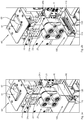
- FIGS. 1a and 1b show oblique views of a preferred embodiment of the packaging device 1 according to the invention, with Figure 1a a web of packaging material 40 guided through the packaging device is omitted in order to illustrate the components located therebelow.
- a blister tube is produced in which two consecutive blister bags "share" a transverse joining area.
- embossing means are arranged accordingly, either in such a way that the patterns are created only in a section of the transverse joining area, this section being assigned to a blister bag.
- the embossing means can be arranged in such a way that patterns are embossed in both sections of the transverse joining area, which are then each assigned to a blister bag.
- the embodiment of the packaging device shown comprises a packaging material feed 30, by means of which the elongate packaging material web 40 is fed via a plurality of rollers to a packaging material guide device 10, the path of the packaging material web in FIG Figure 1b is only shown in sections.
- a guide device 60 is arranged, by means of which provided medicament portions are fed to a receiving area for medicament portions which is formed by a shaped area of the packaging material web.
- the shaped packaging material web is guided vertically downward by the packaging material guide device 10, as can be seen in more detail in the following figures.
- the vertical guidance of the packaging material web defines its direction of travel "downwards".
- the direction of travel can also be different, for example it is conceivable that the direction of movement runs at an angle, in which case the receiving area for the medicament portions is shaped differently (see also in detail on this WO 2016/113291 A1 and WO 2018/184795 A1 ).
- a longitudinal joining device 20 Downstream of the packaging material guide device 10, a longitudinal joining device 20 is arranged, with which an overlap region 41 of the shaped packaging material web 43 extending in the running direction is joined, as described in more detail with reference to the following figures.
- a transverse joining device 100 which comprises two joining means 110, 120, wherein in the embodiment shown the joining means 120 can be moved transversely or orthogonally to the running direction of the packaging material web, as has already been done in FIG Figure 1b is indicated, in which the two joining means 110, 120 for producing a transverse joining area 42 of the packaging material web 40 are brought together.
- the aforementioned devices of the packaging device according to the invention comprise a plurality of drives, as in the Figures 1a and 1b can be seen in part, but their exact functioning and arrangement within the packaging device are not essential for the invention. These are usually rotary motors, the mode of operation of which does not need to be described in detail here.
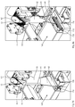
- Figures 2a and 2b show detailed views of the first embodiment, specifically in particular the guide device 60, the packaging material guide device 10, the longitudinal joining device 20 and the transverse joining device 100 Figures 2a and 2b
- Only indicated packaging material guide device 10 is arranged a guide device 60 which comprises a funnel-shaped receiving area 61 for receiving medicament portions.
- the receiving area 61 guides the medicament portions into a guide section 62 with which the medicament portions are guided into a receiving area 45 of the shaped packaging material web 43, as described with reference to FIG Figures 3a and 3b is described in more detail.
- the longitudinal joining device 20 is arranged downstream (in relation to the running direction of the packaging material web) of the packaging material guide device 10.
- This essentially comprises two assemblies, namely a connection assembly having two welding jaws 24a, 24b as well as a movement assembly arranged downstream of this connection assembly, which moves the overlap area joined by the welding jaws by means of the belt drives 21, 23 in the running direction "downwards up".
- a connection assembly having two welding jaws 24a, 24b as well as a movement assembly arranged downstream of this connection assembly, which moves the overlap area joined by the welding jaws by means of the belt drives 21, 23 in the running direction "downwards up".
- an adhesive is applied to the overlapping area prior to joining, for example, and this area is then only pressed together and no heat-welding takes place.
- the transverse joining device 100 Downstream of the longitudinal joining device 20, the transverse joining device 100 is arranged, by means of which the packaging material web, which has already been welded in the longitudinal direction, is inserted into Is joined together in the transverse direction, as a result of which a transverse joining region 42 (shown here exaggeratedly large) is created.
- Figures 3a and 3b show further detailed views, in which the guide device 60 is partially left out and the longitudinal joining device 20 is completely left out.
- the web of packaging material is omitted.
- Figure 3a the course and the shape of the packaging material web within the packaging device according to the invention can be seen in particular.
- the packaging material guide device 10 From the packaging material feed (not shown), the elongated packaging material web arrives at a (in Figure 3b to be recognized) receiving area 11 of the packaging material guide device 10, which has a central through opening 12, towards which the packaging material web is formed.
- the packaging material guide device 10 is designed in the form of a shoulder or collar with the central through opening in the embodiment shown.
- the elongate packaging material web is formed over the shoulder-shaped receiving area 11 to form a tubular packaging material web 43 with a packaging material overlap area 41.
- Figure 3a it can be seen that the packaging material web is guided over this in the area of the receiving area 11 and is correspondingly shaped (reference numeral 44 shows the packaging material web resting on the receiving area 11).
- the packaging material overlap area 41 is of the Figures 2a and 2b
- the welding jaws 24a, 24b shown are initially welded and then moved further in the running direction (that is to say downwards in the embodiment shown) by the conveying means 21, 23.
- the guide section 62 of the guide device is guided through this area for support.
- Figure 3b the exact arrangement of this guide section 62 can be seen.
- the packaging material web is guided through a gap between the guide section 62 and the wall of the through opening 12 in the area of the packaging material guide device.
- the tubular packaging material web is then continued on the outside of the guide section 62.
- the tubular packaging material web is expanded to the receiving area 45 by expansion means 64, which are fastened in the lower region of the guide section 62.
- the medicament portions to be blistered reach this receiving area 45. Due to the already introduced transverse joining area of the leading blister bag, the receiving area 45 is also closed at the bottom. It is true that the use of the expansion means 64 is not absolutely necessary, but their use ensures an error-free and visually appealing joining of the transverse joining area 42.
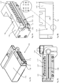
- FIGS 4a and 4b show detailed views of the transverse joining device 100 with the two joining means 110 and 120 Figure 4a
- the embossing means 112 are arranged in the joining means 110 in such a way that the embossing means designed as embossing pins can be extended and retracted in relation to a surface 111 of the joining means 110.
- the joining means 120 can be moved horizontally, that is to say transversely or orthogonally to the running direction of the packaging material web, for which purpose in the embodiment shown a merely indicated Horizontal movement device 128 is provided, the more precise functioning of which is not relevant here.
- FIGs 5a and 5b show detailed views of the joining means 110, which in a (in Figure 6a
- the holder 116 shown is arranged on or in a joining means housing 115.
- the embossing means 112 are designed as twelve 2 * 3 matrices 117, so that twelve Braille characters can be introduced into the transverse joining area with the joining means 110 shown.
- a separating means 130 is provided below the joining means 120, which can be moved horizontally, i.e. transversely or orthogonally to the direction of travel of the packaging material strip and can make a perforation in the transverse joining area or cut it completely.
- Figures 6a and 6b show detailed views of the joining means 110, and in the Figures 6a and 6b it can be seen to some extent that the individual embossing means 112 designed as embossing pins can be moved in and out individually.
- Both Figures 6a and 6b the same position of the embossing pins is illustrated, and two 2 ⁇ 3 matrices are highlighted on the basis of the detailed image, with the lower embossing pin of the first column and the upper embossing pin of the second column in the left-hand highlighted matrix being extended, whereas in the second matrix only the middle die of the second column is extended. How exactly the individual embossing pins are moved is not essential for the present invention and is known to the person skilled in the art, for example from conventional devices for writing in Braille.
- Figure 7 shows a flow chart of a preferred embodiment of the method according to the invention.
- a blister tube is produced in which two consecutive blister bags "share" a transverse joining area.
- the embossing means are arranged accordingly, either in such a way that the patterns are created only in a section of the transverse joining area, this section being assigned to a blister bag.
- the embossing means can be arranged in such a way that patterns can be embossed in both sections of the transverse joining area, which are then each assigned to a blister bag.
- a packaging material web 40 is provided, which is formed into a receiving area 45 in a step 210 for receiving medicament portions. This is done, for example, with the packaging material guide device 10 described in the previous figures.
- the medicament portions to be blistered are supplied to it in a step 220.
- the shaped packaging material web 43 is joined (for example welded) with the longitudinal joining device 20 in a packaging material overlap region 41 in the running direction of the packaging material web to form a tubular packaging material web 43.
- a transverse joining device 100 arranged downstream of the longitudinal joining device 20 is used to join the tubular packaging material web 43 at predetermined intervals in or to form a transverse joining area 42.
- this transverse joining area is the end of the blister pouch that has just been processed and at the same time the "lower" end of a new subsequent blister pouch, the transverse joining area forming a section of the receiving area of the subsequent blister pouch.
- a tactile pattern is embossed in the transverse joining area 42 by means of a plurality of embossing means 112 movable transversely to the direction of travel, the arrangement in the transverse joining area being such that the patterns are one or both Blister bags are assigned.
- the pattern is only assigned to a blister bag;
- patterns for both blister bags can also be stamped into the transverse joining area, which "share" the transverse joining area (as the upper or lower end of the blister bag, regularly separated by a perforation made with a separating agent 130 ).
Landscapes
- Engineering & Computer Science (AREA)
- Mechanical Engineering (AREA)
- Manufacturing & Machinery (AREA)
- Containers And Plastic Fillers For Packaging (AREA)
Abstract
Description
- Die vorliegende Erfindung betrifft eine Verpackungsvorrichtung für Kleinstückgüter, insbesondere Arzneimittelportionen und Nahrungsmittelergänzungsportionen, die Verwendung der Verpackungsvorrichtung sowie ein Verfahren zum Herstellen eines mehrere Blisterbeutel umfassenden Blisterschlauches.
- Vorrichtungen zum Verblistern von Arzneimittelportionen, auch Blisterautomaten gekannt, sind beispielsweise aus der
WO 2013/034504 A1 bekannt. Die Vorrichtungen umfassen, je nach Ausbaustaufe, mehrere hundert Vorrats- und Abgabestationen, in welchen jeweils mehrere Arzneimittelportionen eines bestimmten Arzneimitteltyps gelagert sind. Auf Anforderung können einzelne Arzneimittelportionen von den Vorrats- und Abgabestationen abgegeben und über eine Führungseinrichtung einer Verpackungseinrichtung zugeführt werden, bei welcher die Arzneimittelportionen verpackt bzw. verblistert werden. Verpackungseinrichtungen zur Verwendung in den oben genannten Blisterautomaten sind beispielsweise aus derWO 2016/113291 A1 und derWO 2018/184795 A1 bekannt. - Mit den bei Blisterautomaten verwendeten Verpackungsvorrichtungen werden üblicherweise Blisterschläuche hergestellt, die mehrere Blisterbeutel umfassen. Zur Herstellung der Blisterbeutel bzw. Blisterschläuche wird eine Verpackungsmaterialbahn derart geformt, dass eine oder mehrere Arzneimittelportionen einem Aufnahmebereich zugeführt werden können. Nachdem die zu verblisternden Arzneimittelportionen dem Aufnahmebereich zugeführt sind, werden die einzelnen Blisterbeutel des Blisterschlauches durch Zusammenfügen der Verpackungsmaterialbahn an vorgegebenen Stellen fertiggestellt, wobei sich die Blisterbeutel strangartig über den Blisterschlauch erstrecken.
- Die einzelnen Blisterbeutel enthalten patientenindividuell zusammengestellte Arzneimittelportionen und/oder Nahrungsmittelergänzungsportionen. Einem Patienten werden üblicherweise mehrere Blisterbeutel oder ein Abschnitt des Blisterschlauches bereitgestellt, und der Patient muss anhand der auf einem Blisterbeutel aufgedruckten Einnahmeinformationen erkennen, zu welchem Zeitpunkt eine in einem Blisterbeutel umfasste Arzneimittelzusammenstellung einzunehmen ist, beispielsweise morgens, mittags oder abends. Bei bekannten Verpackungsvorrichtungen werden die für den Patienten bestimmten Einnahmeinformationen vor dem Zusammenfügen des Blisterbeutels auf die Verpackungsmaterialbahn aufgedruckt. Aufgrund der geringen Größe der Blisterbeutel selbst sind auch die aufgedruckten für den Patienten bestimmten Einnahmeinformationen relativ klein gehalten, so dass das Erfassen, also Lesen, der Einnahmeinformationen einem Patienten mit einer Sehbeeinträchtigung schwer fallen kann oder ohne die Verwendung bestimmter Hilfsmittel unmöglich sein kann.
- Es ist Aufgabe der vorliegenden Erfindung, eine Verpackungsvorrichtung für Kleinstückgüter bereitzustellen, mit welcher Blisterbeutel herstellbar sind, deren Einnahmeinformationen auch von Patienten mit einer Sehbeeinträchtigung erfassbar sind. Ferner ist es Aufgabe der vorliegenden Erfindung, ein Verfahren zum Herstellen solcher Blisterbeutel bereitzustellen.
- Die Aufgabe wird zum einen gelöst durch eine Verpackungsvorrichtung für Kleinstückgüter nach Patentanspruch 1. Im Rahmen der vorliegenden Erfindung sollen mit dem Begriff der Kleinstückgüter insbesondere Arzneimittelportionen und Nahrungsmittelergänzungsportionen in z. B. Tablettenform umfasst sein. Die Verpackungsvorrichtung kann aber auch genutzt werden, um andere Kleinstückgüter (beispielsweise Schrauben und dergleichen) zu verpacken.
- Die erfindungsgemäße Verpackungsvorrichtung für Kleinstückgüter, mit welcher Blisterbeutel mit von Personen mit Sehbeeinträchtigungen wahrnehmbaren Einnahmeinformationen hergestellt werden können, umfasst eine Verpackungsmaterial-Führungseinrichtung zum Aufnehmen einer länglichen Verpackungsmaterialbahn, wobei die Verpackungsmaterial-Führungseinrichtung derart ausgebildet ist, dass die längliche Verpackungsmaterialbahn derart geformt wird, dass diese zur Aufnahme von Arzneimittelportionen geeignet ist (d. h. einen Aufnahmebereich für Kleinstückgüter aufweist) und in einer Laufrichtung weitergeführt wird. Wie genau die in die Verpackungsmaterial-Führungseinrichtung eintretende längliche Verpackungsmaterialbahn zum Aufnehmen von Kleinstückgütern geformt wird, ist abhängig von der Art und Weise, wie die zu verpackenden Kleinstückgüter zugeführt werden, wie die Laufrichtung der geformten Verpackungsmaterialbahn verläuft und ob die Verpackungsmaterialbahn beispielsweise schon vorgeformt ist. So ist es beispielsweise denkbar, dass das Verpackungsmaterial bereits in Längs- bzw. Laufrichtung gefaltet zugeführt wird.
- Wenn die Verpackungsmaterialbahn beispielsweise nach der Formgebung senkrecht nach unten geführt wird, wie dies in der
WO 2018/184795 A1 beschrieben ist, wird die Verpackungsmaterialbahn schlauchförmig geformt, wobei das untere Ende des schlauchförmigen Abschnittes durch einen Trennbereich zu einem vorlaufenden bereits geformten Blisterbeutel gebildet ist. In einem solchen Fall werden die Arzneimittelportionen (also die Kleinstückgüter) regelmäßig direkt von oben in den mit der Falt- und Führungseinrichtung gebildeten Aufnahmebereich geleitet. Wenn alternativ die Laufrichtung eher schräg verläuft, wie dies in derWO 2016/113291 A1 beschrieben ist, wird die Verpackungsmaterialbahn zu einer Art nach oben offenem Tetraeder geformt, welcher den Aufnahmebereich für die Arzneimittelportionen bildet. Die genaue bauliche Ausgestaltung der Verpackungsmaterial-Führungseinrichtung ist für die Erfindung nicht wesentlich, solange die oben beschriebene Funktion durch diese erfüllt wird. - Die erfindungsgemäße Verpackungsvorrichtung umfasst stromab der Verpackungsmaterial-Führungseinrichtung ferner eine Längs-Fügeeinrichtung, welche die Verpackungsmaterialbahn bei einem Verpackungsmaterial-Überlappungsbereich in Laufrichtung der Verpackungsmaterialbahn zusammenfügt. Dieser Verpackungsmaterial-Überlappungsbereich kann durch eine spezielle bauliche Ausgestaltung der Verpackungsmaterial-Führungseinrichtung vorgegeben sein.
- Stromab der Verpackungsmaterial-Führungseinrichtung ist ferner eine Quer-Fügeeinrichtung angeordnet, welche die Verpackungsmaterialbahn in vorgegebenen Abständen (bezogen auf die Längsachse bzw. Laufrichtung der Verpackungsmaterialbahn), quer zur Laufrichtung zu einem Quer-Fügebereich zusammenfügt, wobei die Quer-Fügeeinrichtung zwei Fügemittel umfasst, von denen zumindest ein Fügemittel quer zur Laufrichtung bewegbar ist. Dieser Quer-Fügebereich kann dem oberen Trennabschnitt zwischen zwei Blisterbeuteln entsprechen. Dies ist dann der Fall, wenn der Blisterschlauch (wie es üblich ist) derart hergestellt wird, dass der Quer-Fügebereich zwei aufeinanderfolgenden Blisterbeuteln zugeordnet ist, zwischen denen innerhalb des Quer-Fügebereichs beispielsweise eine Perforation zum Abtrennen der einzelnen Blisterbeutel vorgesehen ist. Alternativ kann der Blisterschlauch auch so hergestellt werden, dass jedem Blisterbeutel zwei "eigene" Quer-Fügebereiche zugeordnet sind. Die Längs-Fügeeinrichtung und die Quer-Fügeeinrichtung können in Laufrichtung hintereinander als separate Bauteile angeordnet sein (wobei die Quer-Fügeeinrichtung regelmäßig stromab der Längsfügeeinrichtung angeordnet ist), es ist aber auch denkbar, dass beide Fügeeinrichtungen in einem gemeinsamen Fügebauteil angeordnet sind.
- Die Verpackungsvorrichtung umfasst darüber hinaus erfindungsgemäß eine Mehrzahl von quer zur Längsrichtung einzeln bewegbaren Prägemitteln und einen Prägemittel-Anschlagbereich, wobei die Prägemittel und der Prägemittel-Anschlagbereich derart zusammenwirken, dass mittels der Prägemittel ertastbare Erhebungen in dem Quer-Fügebereich ausbildbar sind.
- Indem in dem Quer-Fügebereich ertastbare Erhebungen ausgebildet werden, ist es auch für einen Patienten mit einer Sehbeeinträchtigung möglich, mehrere Blisterbeutel zu unterscheiden. Wenn einem Patienten beispielsweise pro Tag drei Blisterbeutel bereitgestellt werden, ist es bei der Verwendung von zwei Prägestiften möglich, die drei Blisterbeutel derart durch ein Muster zu markieren, dass diese von dem Patienten zweifelsfrei einem Einnahmezeitpunkt zugeordnet werden können. Die erfindungsgemäße Verpackungseinrichtung ermöglicht es somit, Blisterbeutel bereitzustellen, die auch von einem Patienten mit einer Sehbeeinträchtigung eindeutig einem vorgegebenen Einnahmezeitpunkt zuordenbar sind.
- Wie genau die Prägemittel in der Verpackungsvorrichtung realisiert werden, ist für die vorliegende Erfindung nicht wesentlich, solange sichergestellt ist, dass die ertastbaren Erhebungen in den Quer-Fügebereich eingebracht werden. So ist es beispielsweise denkbar, stromab der Fügeeinrichtungen eine weitere Einrichtung bereitzustellen, die die Prägemittel umfasst und mittels welcher die ertastbaren Erhebungen in die Quer-Fügebereiche eingebracht werden. Um jedoch die Verwendung einer separaten Einrichtung für das Führen der Prägemittel zu vermeiden, ist es bei einer bevorzugten Ausführungsform der erfindungsgemäßen Verpackungsvorrichtung vorgesehen, dass die Prägemittel in einem der Fügemittel ein- und ausfahrbar angeordnet sind und dass das andere Fügemittel zumindest in einem Kontaktbereich eine elastisch ausgebildete Fügeoberfläche oder eine Mehrzahl von quer zur Laufrichtung einzeln bewegbaren Prägemittelaufnahmen aufweist. Bei dieser bevorzugten Ausführungsform werden die ertastbaren Erhebungen also zeitgleich mit dem Herstellen des Quer-Fügebereiches erzeugt, so dass es nicht notwendig ist, mit einer separaten Einrichtung die ertastbaren Erhebungen nach dem Erstellen des Quer-Fügebereiches einzubringen, was die Komplexität und die Baulänge (in Laufrichtung) der Verpackungsvorrichtung vermindert bzw. gering hält.
- Bereits bei der Verwendung von zwei Prägemitteln ist es möglich, die Blisterbeutel derart eindeutig zu kennzeichnen, dass ein Patient vier unterschiedliche Blisterbeutel unterscheiden kann, womit es auch einem Patienten mit einer Sehbeeinträchtigung möglich ist, die Blisterbeutel eines Tagesbedarfes ohne Hilfe unterscheiden zu können. Um eine größere Vielzahl von Blisterbeuteln eindeutig voneinander zu unterscheiden und das Ermitteln der durch die Erhebungen aufgebrachten Informationen zu vereinfachen, ist es bei einer bevorzugten Ausführungsform der erfindungsgemäßen Verpackungsvorrichtung vorgesehen, dass die Prägemittel als zumindest eine 2∗3-Matrix (waagerecht, senkrecht) aus Prägestiften ausgebildet sind, so dass mittels der Prägestifte pro Matrix ein Punktmuster in Form eines Braille-Zeichens erzeugbar ist. Bereits bei Verwendung von lediglich einer Matrix können 64 verschiedene Muster dargestellt werden, so dass in einem solchen Fall Blisterbeutel für beispielsweise eine ganze Woche eindeutig voneinander unterscheidbar sind. Bei Verwendung von größeren und/oder mehreren Matrizen ist es demnach möglich, eine Vielzahl von Daten in den Quer-Fügebereich einzuprägen.
- Das Zusammenfügen der Blisterbeutel aus der langgestreckten Verpackungsmaterialbahn kann auf unterschiedliche Art und Weise stattfinden. Beispielsweise können bestimmte Bereiche vor dem Zusammenfügen mit einem Klebstoff versehen werden. Bei einer bevorzugten Ausführungsform ist es jedoch vorgesehen, dass zumindest eine Fügeoberfläche eines Fügemittels erhitzbar ist, so dass das Zusammenfügen als ein Verschweißen des Verpackungsmaterials stattfindet.
- Wie bereits oben angedeutet, kann die Verpackungsmaterial-Führungseinrichtung in Abhängigkeit von der Gesamtkonstruktion der Verpackungsvorrichtung unterschiedlich ausgeführt sein. Bei einer bevorzugten Ausführungsform umfasst die Verpackungsmaterial-Führungseinrichtung eine zentrale Durchgangsöffnung und ist derart ausgebildet, dass die längliche Verpackungsmaterialbahn der Durchgangsöffnung zugeführt wird, welche derart ausgeführt ist, dass die längliche Verpackungsmaterialbahn in Laufrichtung zu einer von der Durchgangsöffnung definierten schlauchförmigen Verpackungsmaterialbahn mit einem Verpackungsmaterialbahn-Überlappungs-Bereich geformt wird, wobei sich innerhalb eines Abschnittes der schlauchförmigen Verpackungsmaterialbahn ein Führungsabschnitt einer Leiteinrichtung für Arzneimittelportionen erstreckt, welcher in dem Abgabebereich der schlauchförmigen Verpackungsmaterialbahn endet. Um bei einer schlauchförmig geformten Verpackungsmaterialbahn zu gewährleisten, dass die Quer-Zusammenfügung mittels der Quer-Fügeeinrichtung ohne Überlappung der Verpackungsmaterialbahn in dem Quer-Fügebereich fehlerfrei gelingt, ist es bei dieser bevorzugten Ausführungsform vorgesehen, dass im unteren Bereich des Führungsabschnittes mehrere Spreizmittel angeordnet sind, die die schlauchförmige Verpackungsmaterialbahn zum Zusammenfügen durch die Quer-Fügeeinrichtung entsprechend der Ausrichtung der Fügemittel aufspreizen. Mit anderen Worten, die Spreizmittel sorgen dafür, dass die schlauchförmige Verpackungsmaterialbahn vor dem Zusammenfügen an die Ausrichtung der Fügemittel angepasst wird, d. h. aus der kreisförmigen Form in eine langgestreckte Form überführt wird, die mittels der Quer-Fügeeinrichtung besser zusammengefügt werden kann.
- Die Anmeldung betrifft ferner die Verwendung einer erfindungsgemäßen Verpackungsvorrichtung zum Herstellen eines mehrere Blisterbeutel umfassenden Blisterschlauches.
- Die Aufgabe der vorliegenden Erfindung wird ferner gelöst durch ein Verfahren gemäß Patentanspruch 7. Bei dem erfindungsgemäßen Verfahren zum Herstellen eines mehrere Blisterbeutel umfassenden Blisterschlauches wird zunächst eine längliche Verpackungsmaterialbahn bereitgestellt, die dann mit einer Verpackungsmaterial-Führungseinrichtung zur Aufnahme von Arzneimittelportionen zu einem Aufnahmebereich geformt wird. Wie genau diese Formung durchgeführt wird, ist abhängig von der genauen Ausgestaltung der Verpackungsmaterial-Führungseinrichtung, der Laufrichtung der Verpackungsmaterialbahn sowie der genauen Ausgestaltung des Verpackungsmaterials (siehe dazu weiter oben). Nach der Formung zur Aufnahme von Kleinstückgütern werden Kleinstückgüter dem Aufnahmebereich zugeführt und die Verpackungsmaterialbahn mit einer Längs-Fügeeinrichtung bei einem Verpackungsmaterial-Überlappungsbereich in Laufrichtung der Verpackungsmaterialbahn zu einer schlauchförmigen Verpackungsmaterialbahn zusammengefügt, wobei das Zusammenfügen und das Zuführen von Kleinstückgütern auch zeitgleich oder in umgekehrter Reihenfolge erfolgen kann. Mit der Quer-Fügeeinrichtung wird die schlauchförmige Verpackungsmaterialbahn in vorgegebenen Abständen, bezogen auf die Laufrichtung bzw. Längsachse der Verpackungsmaterialbahn, in einem Quer-Fügebereich zusammengefügt, wobei dies auch zeitgleich mit dem Zusammenfügen in Längsrichtung stattfinden kann. Erfindungsgemäß wird in den Quer-Fügebereich mittels einer Mehrzahl von quer zur Laufrichtung bewegbaren Prägemitteln ein ertastbares Muster eingeprägt.
- Bei einer bevorzugten Ausführungsform des erfindungsgemäßen Verfahrens sind die Prägemittel als zumindest eine 2∗3-Matrix aus Prägestiften ausgebildet, so dass mittels der Prägestifte pro Matrix ein Punktmuster in Form eines Braille-Zeichens in den Quer-Fügebereich eingeprägt werden kann. Auf diese Weise kann eine Vielzahl von Informationen mittels ertastbaren Zeichen eingebracht werden, die einem Großteil von Patienten mit Sehbeeinträchtigung bekannt sind.
- Um das Zusammenfügen der vorgeformten Verpackungsmaterialbahn mit der Quer-Fügeeinrichtung zu unterstützen und die Wahrscheinlichkeit von Fügefehlern zu vermindern, ist es bei einer bevorzugten Ausführungsform des Verfahrens vorgesehen, dass die schlauchförmige Verpackungsmaterialbahn vor dem Zusammenfügen durch mehrere Spreizmittel aufgespreizt wird.
- Im Nachfolgenden wird eine bevorzugte Ausführungsform der erfindungsgemäßen Verpackungsvorrichtung sowie des erfindungsgemäßen Verfahrens unter Bezugnahme auf die Zeichnung beschrieben, in welcher
-
Figuren 1a und 1b Schrägansichten der bevorzugten Ausführungsform zeigen, wobei inFigur 1a die Verpackungsmaterialbahn fortgelassen ist, -
Figuren 2a und 2b Detailansichten der Längs- und Quer-Fügeeinrichtungen zeigen, wobei beiFigur 2b die Verpackungsmaterialbahn fortgelassen ist, -
Figuren 3a und 3b Detailansichten der Falt- und Fügeeinrichtung zeigen, wobei beiFigur 3b die Verpackungsmaterialbahn fortgelassen ist, -
Figuren 4a und 4b Detailansichten der Quer-Fügeeinrichtung zeigen, -
Figuren 5a und 5b Schnittansichten der Quer-Fügeeinrichtung zeigen, -
Figuren 6a und 6b Detailansichten eines Fügemittels zeigen, und -
Figur 7 ein Ablaufschema einer bevorzugten Ausführungsform des erfindungsgemäßen Verfahrens zeigt. - Bei den nachfolgend beschriebenen Ausführungsformen wird eine speziell ausgebildete Verpackungsmaterial-Führungseinrichtung beschrieben, die für eine nicht vorgeformte (vorgefaltete) Verpackungsmaterialbahn geeignet ist. Bei der nachfolgenden detaillierten Beschreibung sind Arzneimittelportionen als Kleinstückgüter vorgesehen.
Figuren 1a und 1b zeigen Schrägansichten einer bevorzugten Ausführungsform der erfindungsgemäßen Verpackungsvorrichtung 1, wobei beiFigur 1a eine durch die Verpackungsvorrichtung geführte Verpackungsmaterialbahn 40 fortgelassen ist, um die darunter befindlichen Bauteile zu veranschaulichen. Bei der nachfolgend beschriebenen bevorzugten Ausführungsform der Verpackungsvorrichtung wird ein Blisterschlauch hergestellt, bei dem sich zwei aufeinanderfolgende Blisterbeutel einen Quer-Fügebereich "teilen". Dies bedingt, dass die Prägemittel entsprechend angeordnet sind, und zwar entweder so, dass die Muster nur in einem Abschnitt des Quer-Fügebereichs erstellt werden, wobei dieser Abschnitt einem Blisterbeutel zugeordnet ist. Alternativ können die Prägemittel so angeordnet sein, dass in beiden Abschnitten des Quer-Fügebereichs Muster geprägt werden, die dann jeweils einem Blisterbeutel zugeordnet sind. - Die gezeigte Ausführungsform der Verpackungsvorrichtung umfasst eine Verpackungsmaterial-Zuführung 30, mittels welcher die längliche Verpackungsmaterialbahn 40 über eine Mehrzahl von Rollen einer Verpackungsmaterial-Führungseinrichtung 10 zugeführt wird, wobei der Laufweg der Verpackungsmaterialbahn in
Figur 1b lediglich abschnittsweise gezeigt ist. Über der Verpackungsmaterial-Führungseinrichtung 10, die in nachfolgenden Figuren detaillierter beschrieben ist, ist eine Leiteinrichtung 60 angeordnet, mittels welcher bereitgestellte Arzneimittelportionen einem Aufnahmebereich für Arzneimittelportionen, welcher durch einen geformten Bereich der Verpackungsmaterialbahn gebildet ist, zugeführt werden. Von der Verpackungsmaterial-Führungseinrichtung 10 wird bei der bevorzugten Ausführungsform der gezeigten Verpackungsvorrichtung die geformte Verpackungsmaterialbahn senkrecht nach unten geführt, wie dies in nachfolgenden Figuren detaillierter zu erkennen ist. Durch die senkrechte Führung der Verpackungsmaterialbahn ist deren Laufrichtung "nach unten" festgelegt. Bei abweichenden Ausführungen der Leiteinrichtung sowie der Verpackungsmaterial-Führungseinrichtung kann die Laufrichtung auch abweichend sein, beispielsweise ist es denkbar, dass die Laufrichtung schräg verläuft, wobei in einem solchen Fall der Aufnahmebereich für die Arzneimittelportionen anders geformt ist (siehe dazu im Detail auchWO 2016/113291 A1 undWO 2018/184795 A1 ). - Stromab der Verpackungsmaterial-Führungseinrichtung 10 ist eine Längs-Fügeeinrichtung 20 angeordnet, mit welcher ein sich in Laufrichtung erstreckender Überlappungsbereich 41 der geformten Verpackungsmaterialbahn 43 zusammengefügt wird, wie dies unter Bezugnahme auf nachfolgende Figuren detaillierter beschrieben ist.
- Stromab dieser Längs-Fügeeinrichtung 20 ist eine Quer-Fügeeinrichtung 100 angeordnet, die zwei Fügemittel 110, 120 umfasst, wobei bei der gezeigten Ausführungsform das Fügemittel 120 quer bzw. orthogonal zu der Laufrichtung der Verpackungsmaterialbahn bewegbar ist, wie dies bereits in
Figur 1b angedeutet ist, in welcher die beiden Fügemittel 110, 120 zum Herstellen eines Quer-Fügebereiches 42 der Verpackungsmaterialbahn 40 zusammengeführt sind. Die vorgenannten Einrichtungen der erfindungsgemäßen Verpackungsvorrichtung umfassen eine Mehrzahl von Antrieben, wie in denFiguren 1a und 1b teilweise zu erkennen ist, deren genaue Funktionsweise und Anordnung innerhalb der Verpackungsvorrichtung aber für die Erfindung unwesentlich sind. Es handelt sich regelmäßig um Drehmotoren, deren Funktionsweise hier nicht näher beschrieben werden muss. -
Figuren 2a und 2b zeigen Detailansichten der ersten Ausführungsform, und zwar insbesondere die Leiteinrichtung 60, die Verpackungsmaterial-Führungseinrichtung 10, die Längs-Fügeeinrichtung 20 sowie die Quer-Fügeeinrichtung 100. Über der in denFiguren 2a und 2b lediglich angedeuteten Verpackungsmaterial-Führungseinrichtung 10 ist eine Leiteinrichtung 60 angeordnet, die einen trichterförmigen Aufnahmebereich 61 zur Aufnahme von Arzneimittelportionen umfasst. Der Aufnahmebereich 61 leitet die Arzneimittelportionen in einen Führungsabschnitt 62, mit welchem die Arzneimittelportionen in einen Aufnahmebereich 45 der geformten Verpackungsmaterialbahn 43 geführt werden, wie dies unter Bezugnahme aufFiguren 3a und 3b detaillierter beschrieben ist. Stromab (bezogen auf die Laufrichtung der Verpackungsmaterialbahn) der Verpackungsmaterial-Führungseinrichtung 10 ist die Längs-Fügeeinrichtung 20 angeordnet. Diese umfasst im Wesentlichen zwei Baugruppen, nämlich eine zwei Schweißbacken 24a, 24b aufweisende Verbindungsbaugruppe sowie eine stromab dieser Verbindungsbaugruppe angeordnete Bewegungsbaugruppe, welche den durch die Schweißbacken zusammengefügten Überlappungsbereich mittels der Bandantriebe 21, 23 in Laufrichtung "nach unten auf" fortbewegt. Bei alternativen Ausführungsformen ist es denkbar, dass anstatt der Schweißbacken 24a, 24b der Überlappungsbereich vor dem Zusammenfügen beispielsweise mit einem Klebstoff beaufschlagt wird, und dieser Bereich im Anschluss daran lediglich zusammengepresst wird und keine Verschweißung mittels Hitze stattfindet. Stromab der Längs-Fügeeinrichtung 20 ist die Quer-Fügeeinrichtung 100 angeordnet, mittels welcher die bereits in Längsrichtung verschweißte Verpackungsmaterialbahn in Querrichtung zusammengefügt wird, wodurch ein (hier übertrieben groß dargestellter) Quer-Fügebereich 42 entsteht. -
Figuren 3a und 3b zeigen weitere Detailansichten, wobei bei diesen die Leiteinrichtung 60 teilweise und die Längs-Fügeeinrichtung 20 vollständig fortgelassen sind. Darüber hinaus ist beiFigur 3b die Verpackungsmaterialbahn fortgelassen. InFigur 3a ist insbesondere der Lauf und die Formgebung der Verpackungsmaterialbahn innerhalb der erfindungsgemäßen Verpackungsvorrichtung zu erkennen. Von der (nicht dargestellten) Verpackungsmaterial-Zuführung gelangt die längliche Verpackungsmaterialbahn auf einen (inFigur 3b zu erkennenden) Aufnahmebereich 11 der Verpackungsmaterial-Führungseinrichtung 10, die eine zentrale Durchgangsöffnung 12 aufweist, hin zu welcher die Verpackungsmaterialbahn geformt wird. Dazu ist die Verpackungsmaterial-Führungseinrichtung 10 bei der gezeigten Ausführungsform schulter- bzw. kragenförmig mit der zentralen Durchgangsöffnung ausgebildet. Aufgrund der genauen Ausgestaltung der Verpackungsmaterial-Führungseinrichtung 10 wird die längliche Verpackungsmaterialbahn über den schulterförmigen Aufnahmebereich 11 zu einer schlauchförmigen Verpackungsmaterialbahn 43 mit einem Verpackungsmaterial-Überlappungsbereich 41 geformt. InFigur 3a ist zu erkennen, dass die Verpackungsmaterialbahn im Bereich des Aufnahmebereichs 11 über diesen geführt wird und entsprechend geformt wird (Bezugszeichen 44 zeigt die auf dem Aufnahmebereich 11 aufliegende Verpackungsmaterialbahn). - Der Verpackungsmaterial-Überlappungsbereich 41 wird von den in den
Figuren 2a und 2b dargestellten Schweißbacken 24a, 24b zunächst verschweißt und anschließend durch die Fördermittel 21, 23 in Laufrichtung (das heißt bei der gezeigten Ausführungsform nach unten) weiterbewegt. Um zu gewährleisten, dass die durch die Verpackungsmaterial-Führungseinrichtung mit ihrer zentralen Durchgangsöffnung 12 vorgegebene Form der Verpackungsmaterialbahn, nämlich schlauchförmig, beibehalten wird, ist zur Unterstützung durch diesen Bereich der Führungsabschnitt 62 der Leiteinrichtung geführt. InFigur 3b ist die genaue Anordnung dieses Führungsabschnittes 62 zu erkennen. Anhand eines Vergleiches derFiguren 3a und 3b ist ebenfalls zu erkennen, dass die Verpackungsmaterialbahn im Bereich der Verpackungsmaterial-Führungseinrichtung durch einen Spalt zwischen Führungsabschnitt 62 und der Wandung der Durchgangsöffnung 12 geführt ist. Im Anschluss daran wird die schlauchförmige Verpackungsmaterialbahn außen an dem Führungsabschnitt 62 weitergeführt. - Wie dies in den
Figuren 3a und 3b zu erkennen ist, wird die schlauchförmige Verpackungsmaterialbahn durch Spreizmittel 64, die im unteren Bereich des Führungsabschnittes 62 befestigt sind, zu dem Aufnahmebereich 45 aufgespreizt. In diesen Aufnahmebereich 45 gelangen die zu verblisternden Arzneimittelportionen. Aufgrund des bereits eingebrachten Quer-Fügebereiches des vorlaufenden Blisterbeutels ist der Aufnahmebereich 45 auch nach unten abgeschlossen. Zwar ist die Verwendung der Spreizmittel 64 nicht zwingend erforderlich, jedoch gewährleistet deren Verwendung eine fehlerfreie und optisch ansprechende Zusammenfügung des Quer-Fügebereiches 42. - Im Hinblick auf eine mögliche Ausgestaltung der Verpackungsmaterial-Führungseinrichtung sowie der Leiteinrichtung und der Längs-Fügeeinrichtung wird noch Bezug genommen auf die Anmeldung
WO 2018/184795 A1 , deren für die vorgenannten Einrichtungen relevanter Offenbarungsgehalt hiermit in diese Anmeldung aufgenommen wird. -
Figuren 4a und 4b zeigen Detailansichten der Quer-Fügeeinrichtung 100 mit den beiden Fügemitteln 110 und 120. BeiFigur 4a ist zu erkennen, dass bei der hier gezeigten bevorzugten Ausführungsform der erfindungsgemäßen Verpackungsvorrichtung die Prägemittel 112 in dem Fügemittel 110 angeordnet sind, und zwar derart, dass die als Prägestifte ausgebildeten Prägemittel in Bezug auf eine Oberfläche 111 des Fügemittels 110 aus- und einfahrbar sind. Bei der hier gezeigten Ausführungsform ist lediglich das Fügemittel 120 horizontal, also quer bzw. orthogonal zur Laufrichtung der Verpackungsmaterialbahn, bewegbar, wozu bei der gezeigten Ausführungsform eine lediglich angedeutete Horizontalbewegungseinrichtung 128 vorgesehen ist, deren genauere Funktionsweise hier nicht relevant ist. - Damit mit den ein- und ausfahrbaren Prägestiften 112 ein ertastbares Muster in den Quer-Fügebereich eingebracht werden kann, ist es notwendig, dass diese mit einem elastisch ausgebildeten Anschlagbereich zusammenwirken, der in dem Fügemittel 120 ausgebildet ist, was anhand der Figuren jedoch optisch nicht zu erkennen ist.
-
Figuren 5a und 5b zeigen Detailansichten des Fügemittels 110, welches in einer über eine (inFigur 6a gezeigte) Halterung 116 an bzw. in einem Fügemittel-Gehäuse 115 angeordnet ist. Wie dies insbesondere inFigur 5b zu erkennen ist, sind bei der gezeigten Ausführungsform die Prägemittel 112 als zwölf 2∗3-Matrizen 117 ausgebildet, so dass mit dem gezeigten Fügemittel 110 zwölf Braille-Zeichen in den Quer-Fügebereich eingebracht werden können. Um die Trennung der einzelnen Blisterbeutel zu vereinfachen, ist unterhalb des Fügemittels 120 ein Trennmittel 130 vorgesehen, welches horizontal, also quer bzw. orthogonal zur Laufrichtung des Verpackungsmaterialbandes, bewegbar ist und eine Perforierung in den Quer-Fügebereich einbringen kann oder diesen vollständig durchtrennen kann. -
Figuren 6a und 6b zeigen Detailansichten des Fügemittels 110, und bei denFiguren 6a und 6b ist ansatzweise zu erkennen, dass die einzelnen, als Prägestifte ausgebildeten Prägemittel 112 einzeln bewegbar ein- und ausfahrbar sind. Bei denFiguren 6a und 6b ist die gleiche Stellung der Prägestifte veranschaulicht, und anhand der Detailaufnahme sind zwei 2∗3-Matrizen hervorgehoben, wobei bei der linken hervorgehobenen Matrix der untere Prägestift der ersten Spalte und der obere Prägestift der zweiten Spalte ausgefahren sind, wohingegen bei der zweiten Matrix lediglich der mittlere Prägestift der zweiten Spalte ausgefahren ist. Wie genau die einzelnen Prägestifte bewegt werden, ist für die vorliegende Erfindung nicht wesentlich und dem Fachmann bekannt, beispielsweise aus üblichen Vorrichtungen zum Schreiben in Braille-Schrift. -
Figur 7 zeigt ein Ablaufschema einer bevorzugten Ausführungsform des erfindungsgemäßen Verfahrens. Bei der nachfolgend beschriebenen bevorzugten Ausführungsform des Verfahrens wird ein Blisterschlauch hergestellt, bei dem sich zwei aufeinanderfolgende Blisterbeutel einen Quer-Fügebereich "teilen". Dies bedingt, dass die Prägemittel entsprechend angeordnet sind, und zwar entweder so, dass die Muster nur in einem Abschnitt des Quer-Fügebereichs erstellt werden, wobei dieser Abschnitt einem Blisterbeutel zugeordnet ist. Alternativ können die Prägemittel so angeordnet sein, dass in beiden Abschnitten des Quer-Fügebereichs Muster geprägt werden kann, die dann jeweils einem Blisterbeutel zugeordnet sind. - Zunächst wird in einem Schritt 200 eine Verpackungsmaterialbahn 40 bereitgestellt, welche in einem Schritt 210 zur Aufnahme von Arzneimittelportionen zu einem Aufnahmebereich 45 geformt wird. Dies geschieht beispielsweise mit der in den vorherigen Figuren beschriebenen Verpackungsmaterial-Führungseinrichtung 10. Nach dem Ausbilden des Aufnahmebereiches 45 werden diesem in einem Schritt 220 die zu verblisternden Arzneimittelportionen zugeführt. In einem Schritt 230 wird die geformte Verpackungsmaterialbahn 43 mit der Längs-Fügeeinrichtung 20 bei einem Verpackungsmaterial-Überlappungsbereich 41 in Laufrichtung der Verpackungsmaterialbahn zu einer schlauchförmigen Verpackungsmaterialbahn 43 zusammengefügt (beispielsweise verschweißt). In einem nachfolgenden Schritt 240 wird mit einer stromab der Längs-Fügeeinrichtung 20 angeordneten Quer-Fügeeinrichtung 100 die schlauchförmige Verpackungsmaterialbahn 43 in vorgegebenen Abständen in einem bzw. zu einem Quer-Fügebereich 42 zusammengefügt. Bei Betrachtung in Laufrichtung ist dieser Quer-Fügebereich der Abschluss des gerade bearbeiteten Blisterbeutels und gleichzeitig das "untere" Ende eines neuen nachfolgenden Blisterbeutels, wobei der Quer-Fügebereich einen Abschnitt des Aufnahmebereichs des nachfolgenden Blisterbeutels bildet. Erfindungsgemäß wird in Schritt 250 im Quer-Fügebereich 42 mittels einer Mehrzahl von quer zur Laufrichtung bewegbaren Prägemitteln 112 ein ertastbares Muster eingeprägt, wobei die Anordnung in dem Quer-Fügebereich derart ist, dass die Muster einem oder beiden Blisterbeutel/-n zugeordnet sind. Bei der hier beschriebenen Ausführungsform der Vorrichtung und des Verfahrens ist das Muster lediglich einem Blisterbeutel zugeordnet; bei Verwendung von Fügemitteln mit komplexeren Prägemitteln können in den Quer-Fügebereich auch Muster für beide Blisterbeutel eingeprägt werden, die sich den Quer-Fügebereich "teilen" (als oberen bzw. unteren Abschluss der Blisterbeutel, regelmäßig getrennt durch eine mit einem Trennmittel 130 eingebrachte Perforation).
Claims (9)
- Verpackungsvorrichtung (1) für Kleinstückgüter, aufweisend:eine Verpackungsmaterial-Führungseinrichtung (10) zum Aufnehmen einer länglichen Verpackungsmaterialbahn (40), wobei die Verpackungsmaterial-Führungseinrichtung (10) derart ausgebildet ist, dass die längliche Verpackungsmaterialbahn (40) derart geformt wird, dass diese zur Aufnahme von Kleinstückgütern geeignet ist und in einer Laufrichtung weitergeführt wird,eine stromab der Verpackungsmaterial-Führungseinrichtung (10) angeordnete Längs-Fügeeinrichtung (20), welche die geformte Verpackungsmaterialbahn (43) bei einem Verpackungsmaterial-Überlappungsbereich (41) in Laufrichtung der Verpackungsmaterialbahn zusammenfügt,eine stromab der Verpackungsmaterial-Führungseinrichtung (10) angeordnete Quer-Fügeeinrichtung (100), welche die geformte Verpackungsmaterialbahn (43) in vorgegebenen Abständen quer zur Laufrichtung zu einem Quer-Fügebereich (42) zusammenfügt, wobei die Quer-Fügeeinrichtung (100) zwei Fügemittel (110, 120) umfasst, von denen zumindest ein Fügemittel quer zur Laufrichtung bewegbar ist,gekennzeichnet durcheine Mehrzahl von quer zur Laufrichtung einzeln bewegbare Prägemittel (112) und einen Prägemittel-Anschlagbereich, die derart zusammenwirken, dass mittels der Prägemittel (112) ertastbare Erhebungen in dem Quer-Fügebereich ausbildbar sind.
- Verpackungsvorrichtung (1) für Kleinstückgüter nach Anspruch 1, dadurch gekennzeichnet, dass die Prägemittel (112) in einem der Fügemittel (110) ein- und ausfahrbar angeordnet sind und das andere Fügemittel (120) zumindest in einem Kontaktbereich eine elastisch ausgebildete Fügeoberfläche (121) oder eine Mehrzahl von quer zur Laufrichtung einzeln bewegbaren Prägemittelaufnahmen aufweist.
- Verpackungsvorrichtung (1) für Kleinstückgüter nach Anspruch 1 oder 2, dadurch gekennzeichnet,
dass die Prägemittel (112) als zumindest eine 2∗3-Matrix (117) aus Prägestiften ausgebildet sind, so dass mittels der Prägestifte pro Matrix ein ertastbares Punktmuster in Form eines Braille-Zeichens erzeugbar ist. - Verpackungsvorrichtung (1) für Kleinstückgüter nach einem der Ansprüche 1 - 3, dadurch gekennzeichnet,
dass zumindest eine Fügeoberfläche (111, 121) eines Fügemittels (110, 120) erhitzbar ist. - Verpackungsvorrichtung (1) für Kleinstückgüter nach einem der Ansprüche 1 - 4,
wobei die Verpackungsmaterial-Führungseinrichtung (10) eine zentrale Durchgangsöffnung (12) aufweist und derart ausgebildet ist, dass die längliche Verpackungsmaterialbahn (40) der Durchgangsöffnung (12) zugeführt wird, welche derart ausgeführt ist, dass die längliche Verpackungsmaterialbahn (40) in Laufrichtung zu einer von der Durchgangsöffnung (12) definierten schlauchförmigen Verpackungsmaterialbahn (43) mit einem Verpackungsmaterial-Überlappungsbereich (41) geformt wird,
wobei sich innerhalb eines Abschnittes der schlauchförmigen Verpackungsmaterialbahn (43) ein Führungsabschnitt (62) erstreckt,
dadurch gekennzeichnet, dass im unteren Bereich (63) des Führungsabschnittes (62) mehrere Spreizmittel (64) angeordnet sind, die die schlauchförmige Verpackungsmaterialbahn (43) zum Ausbilden eines Aufnahmebereichs (45) für Arzneimittelportionen und zum Vorbereiten des Zusammenfügens durch die Quer-Fügeeinrichtung (100) entsprechend der Ausrichtung der Fügemittel (110, 120) aufspreizen. - Verwendung einer Verpackungsvorrichtung (1) nach einem der Ansprüche 1 - 5 zum Herstellen eines mehrere Blisterbeutel umfassenden Blisterschlauches.
- Verfahren zum Herstellen eines mehrere Blisterbeutel umfassenden Blisterschlauches, wobei
eine Verpackungsmaterialbahn (40) bereitgestellt wird,
die Verpackungsmaterialbahn (40) zur Aufnahme von Arzneimittelportionen zu einem Aufnahmebereich (45) geformt wird,
Kleinstückgüter dem Aufnahmebereich (45) zugeführt werden,
mit einer Längs-Fügeeinrichtung (20) die geformte Verpackungsmaterialbahn (43) bei einem Verpackungsmaterial-Überlappungsbereich (41) in Laufrichtung der Verpackungsmaterialbahn zu einer schlauchförmigen Verpackungsmaterialbahn (43) zusammengefügt wird, wobei das Zusammenfügen auch während oder vor der Zuführung der Kleinstückgüter stattfinden kann,
mittels einer Quer-Fügeeinrichtung (100) die schlauchförmige Verpackungsmaterialbahn (43) in vorgegebenen Abständen, bezogen auf die Laufrichtung, in einem Quer-Fügebereich (42) zusammengefügt wird,
dadurch gekennzeichnet, dass im Quer-Fügebereich (42) mittels einer Mehrzahl von quer zur Laufrichtung bewegbaren Prägemitteln (112) ein ertastbares Muster eingeprägt wird. - Verfahren zum Herstellen eines mehrere Blisterbeutel umfassenden Blisterschlauches nach Anspruch 7, dadurch gekennzeichnet,
dass die Prägemittel (112) als zumindest eine 2∗3-Matrix (117) aus Prägestiften ausgebildet sind, so dass mittels der Prägestifte pro Matrix ein Punktmuster in Form eines Braille-Zeichens in dem Quer-Fügebereich eingeprägt wird. - Verfahren zum Herstellen eines mehrere Blisterbeutel umfassenden Blisterschlauches nach Anspruch 7 oder 8, dadurch gekennzeichnet,
dass die schlauchförmige Verpackungsmaterialbahn (43) vor dem Zusammenfügen mittels der Quer-Fügeeinrichtung (100) durch mehrere Spreizmittel (64) aufgespreizt wird.
Priority Applications (5)
| Application Number | Priority Date | Filing Date | Title |
|---|---|---|---|
| EP20175582.4A EP3912918B1 (de) | 2020-05-20 | 2020-05-20 | Verpackungsvorrichtung für kleinstückgüter und verfahren zum herstellen eines mehrere blisterbeutel umfassenden blisterschlauches |
| CN202180036517.4A CN115667072B (zh) | 2020-05-20 | 2021-04-30 | 包装设备及其用于制造连体泡罩袋的用途和方法 |
| PCT/EP2021/061432 WO2021233661A1 (de) | 2020-05-20 | 2021-04-30 | Verpackungsvorrichtung für kleinstückgüter und verfahren zum herstellen eines mehrere blisterbeutel umfassenden blisterschlauches |
| JP2022570488A JP7637699B2 (ja) | 2020-05-20 | 2021-04-30 | 小物品包装装置および複数のブリスター袋を含むブリスターチューブの製造方法 |
| KR1020227039387A KR20230011296A (ko) | 2020-05-20 | 2021-04-30 | 작은 개별물품을 위한 포장 장치 및 복수의 블리스터 백을 포함하는 블리스터 튜브를 생산하는 방법 |
Applications Claiming Priority (1)
| Application Number | Priority Date | Filing Date | Title |
|---|---|---|---|
| EP20175582.4A EP3912918B1 (de) | 2020-05-20 | 2020-05-20 | Verpackungsvorrichtung für kleinstückgüter und verfahren zum herstellen eines mehrere blisterbeutel umfassenden blisterschlauches |
Publications (3)
| Publication Number | Publication Date |
|---|---|
| EP3912918A1 true EP3912918A1 (de) | 2021-11-24 |
| EP3912918C0 EP3912918C0 (de) | 2025-07-02 |
| EP3912918B1 EP3912918B1 (de) | 2025-07-02 |
Family
ID=70779575
Family Applications (1)
| Application Number | Title | Priority Date | Filing Date |
|---|---|---|---|
| EP20175582.4A Active EP3912918B1 (de) | 2020-05-20 | 2020-05-20 | Verpackungsvorrichtung für kleinstückgüter und verfahren zum herstellen eines mehrere blisterbeutel umfassenden blisterschlauches |
Country Status (5)
| Country | Link |
|---|---|
| EP (1) | EP3912918B1 (de) |
| JP (1) | JP7637699B2 (de) |
| KR (1) | KR20230011296A (de) |
| CN (1) | CN115667072B (de) |
| WO (1) | WO2021233661A1 (de) |
Cited By (1)
| Publication number | Priority date | Publication date | Assignee | Title |
|---|---|---|---|---|
| EP4400434A1 (de) * | 2023-01-13 | 2024-07-17 | Becton Dickinson Rowa Germany GmbH | Füllrohr-einführeinrichtungs-system, verfahren zum befestigen eines füllrohrs sowie verwendung einer einführeinrichtung |
Citations (8)
| Publication number | Priority date | Publication date | Assignee | Title |
|---|---|---|---|---|
| US2200971A (en) * | 1939-03-04 | 1940-05-14 | Stokes & Smith Co | System for making, filling, and sealing containers |
| US4018029A (en) * | 1975-10-07 | 1977-04-19 | Hayssen Manufacturing Co. | Packaging apparatus |
| JP2003291910A (ja) * | 2002-03-29 | 2003-10-15 | Nippon Seiki Co Ltd | 充填包装袋の製造方法およびその充填包装装置 |
| EP1740466A1 (de) * | 2004-04-14 | 2007-01-10 | IMA Industria Macchine Automatiche S.p.A. | Verfahren zur herstellung von verpackungsmaterial in form eines mehrlagigen bands |
| DE202008003929U1 (de) * | 2008-03-20 | 2008-05-29 | Haver & Boecker Ohg | Füllmaschine zum Füllen von Behältnissen |
| WO2013034504A1 (en) | 2011-09-09 | 2013-03-14 | Carefusion Switzerland 317 Sàrl | System and method for packaging dosed quantities of solid drug portions |
| WO2016113291A1 (de) | 2015-01-16 | 2016-07-21 | Carefusion Germany 326 Gmbh | Verpackungsvorrichtung für arzneimittel |
| WO2018184795A1 (de) | 2017-04-07 | 2018-10-11 | Becton Dickinson Rowa Germany Gmbh | Vorrichtung zum verpacken von arzneimittelportionen |
Family Cites Families (5)
| Publication number | Priority date | Publication date | Assignee | Title |
|---|---|---|---|---|
| DE10122635A1 (de) * | 2001-05-10 | 2002-11-14 | Natec Reich Summer Gmbh Co Kg | Dreidimensional verpackter Schmelzkäse |
| JP2003026253A (ja) * | 2001-07-13 | 2003-01-29 | Orihiro Engineering Co Ltd | 包装袋、該包装袋の製造方法、および製袋充填包装機 |
| CN101891020B (zh) * | 2009-05-19 | 2014-10-08 | 利乐拉瓦尔集团及财务有限公司 | 填充机中防止不正确粘贴的装置和方法 |
| JP4847566B2 (ja) * | 2009-08-26 | 2011-12-28 | 大成ラミック株式会社 | 包装袋の製造方法および製造装置 |
| JP6253074B1 (ja) * | 2016-07-19 | 2017-12-27 | ヒライ商事株式会社 | 包装袋の密封装置 |
-
2020
- 2020-05-20 EP EP20175582.4A patent/EP3912918B1/de active Active
-
2021
- 2021-04-30 WO PCT/EP2021/061432 patent/WO2021233661A1/de not_active Ceased
- 2021-04-30 JP JP2022570488A patent/JP7637699B2/ja active Active
- 2021-04-30 CN CN202180036517.4A patent/CN115667072B/zh active Active
- 2021-04-30 KR KR1020227039387A patent/KR20230011296A/ko active Pending
Patent Citations (8)
| Publication number | Priority date | Publication date | Assignee | Title |
|---|---|---|---|---|
| US2200971A (en) * | 1939-03-04 | 1940-05-14 | Stokes & Smith Co | System for making, filling, and sealing containers |
| US4018029A (en) * | 1975-10-07 | 1977-04-19 | Hayssen Manufacturing Co. | Packaging apparatus |
| JP2003291910A (ja) * | 2002-03-29 | 2003-10-15 | Nippon Seiki Co Ltd | 充填包装袋の製造方法およびその充填包装装置 |
| EP1740466A1 (de) * | 2004-04-14 | 2007-01-10 | IMA Industria Macchine Automatiche S.p.A. | Verfahren zur herstellung von verpackungsmaterial in form eines mehrlagigen bands |
| DE202008003929U1 (de) * | 2008-03-20 | 2008-05-29 | Haver & Boecker Ohg | Füllmaschine zum Füllen von Behältnissen |
| WO2013034504A1 (en) | 2011-09-09 | 2013-03-14 | Carefusion Switzerland 317 Sàrl | System and method for packaging dosed quantities of solid drug portions |
| WO2016113291A1 (de) | 2015-01-16 | 2016-07-21 | Carefusion Germany 326 Gmbh | Verpackungsvorrichtung für arzneimittel |
| WO2018184795A1 (de) | 2017-04-07 | 2018-10-11 | Becton Dickinson Rowa Germany Gmbh | Vorrichtung zum verpacken von arzneimittelportionen |
Cited By (2)
| Publication number | Priority date | Publication date | Assignee | Title |
|---|---|---|---|---|
| EP4400434A1 (de) * | 2023-01-13 | 2024-07-17 | Becton Dickinson Rowa Germany GmbH | Füllrohr-einführeinrichtungs-system, verfahren zum befestigen eines füllrohrs sowie verwendung einer einführeinrichtung |
| WO2024149492A1 (de) * | 2023-01-13 | 2024-07-18 | Becton Dickinson Rowa Germany Gmbh | Füllrohr-einführeinrichtungs-system, verfahren zum befestigen eines füllrohrs sowie verwendung einer einführeinrichtung |
Also Published As
| Publication number | Publication date |
|---|---|
| WO2021233661A1 (de) | 2021-11-25 |
| EP3912918C0 (de) | 2025-07-02 |
| JP2023526844A (ja) | 2023-06-23 |
| KR20230011296A (ko) | 2023-01-20 |
| EP3912918B1 (de) | 2025-07-02 |
| CN115667072A (zh) | 2023-01-31 |
| JP7637699B2 (ja) | 2025-02-28 |
| CN115667072B (zh) | 2026-06-26 |
Similar Documents
| Publication | Publication Date | Title |
|---|---|---|
| DE3882585T2 (de) | Verfahren und Apparat zum ineinanderfalten von Bahnen. | |
| DE69407820T2 (de) | Umroller zur herstellung von rollen aus bahnmaterial, wahlweise mit oder ohne wickelkern | |
| EP3385174B1 (de) | Vorrichtung zum verpacken von arzneimittelportionen | |
| DE69708088T2 (de) | Ordner mit einer tasche | |
| EP0162119A1 (de) | Vorrichtung zum Herstellen eines Behälters aus einem flachen Zuschnitt | |
| EP0569887A1 (de) | Einrichtung zum Sammeln und Heften von gefalteten Druckereiprodukten | |
| EP1105333A1 (de) | Verfahren und vorrichtung zur perforation von materialbahnen | |
| DE3781150T2 (de) | Broschüre oder ähnliches, verfahren und vorrichtung zu deren herstellung. | |
| EP3912918B1 (de) | Verpackungsvorrichtung für kleinstückgüter und verfahren zum herstellen eines mehrere blisterbeutel umfassenden blisterschlauches | |
| DE69502995T2 (de) | Maschine zum Verpacken von Kleidungsstücken, wie Strümpfe oder dergleichen, in Schachteln | |
| DE10028084C1 (de) | Ärmelseparator und Vorrichtung zu dessen Herstellung | |
| EP0250758A1 (de) | Falz- und Transportvorrichtung | |
| DE2701517A1 (de) | Einrichtung und verfahren zum verbinden der freien enden zweier buendel faecherfoermig gefalteter papierblaetter | |
| DE4425042B4 (de) | Mitnehmer mit Schnellbefestigung | |
| EP1896266B1 (de) | Rollenrotationsdruckmaschine mit formzylinderbelegung | |
| EP0332160A2 (de) | Münzen-Stapelvorrichtung | |
| DE3113951C2 (de) | Verfahren und Vorrichtung zur Herstellung von trichterförmigen Filtereinsätzen mit Öffnungshilfen | |
| WO1998035901A1 (de) | Vorrichtung zum herstellen von mehrteiligen druckereiprodukten | |
| DE19537099A1 (de) | Verfahren und Vorrichtung zur Herstellung von zusätzlichen gefalteten Abschnitten in einer Verpackungsmaschine | |
| DE69106342T2 (de) | Maschine zum herstellen von sitzschutzblättern. | |
| DE4140365A1 (de) | Querschneider zur fertigbehandlung von materialbahnen | |
| EP0664226A1 (de) | Verfahren und Vorrichtung zum Klebverbinden der Bogen eines mehrblättrigen gefalteten Druckereiprodukts | |
| DE3936320C2 (de) | ||
| EP2767495B1 (de) | Bündel mit unterschiedlichen Beipackzetteln und Verfahren zum Herstellen eines solchen Bündels | |
| EP4530207A1 (de) | Vorrichtung zum aufhalten der öffnung eines beutels |
Legal Events
| Date | Code | Title | Description |
|---|---|---|---|
| PUAI | Public reference made under article 153(3) epc to a published international application that has entered the european phase |
Free format text: ORIGINAL CODE: 0009012 |
|
| STAA | Information on the status of an ep patent application or granted ep patent |
Free format text: STATUS: THE APPLICATION HAS BEEN PUBLISHED |
|
| AK | Designated contracting states |
Kind code of ref document: A1 Designated state(s): AL AT BE BG CH CY CZ DE DK EE ES FI FR GB GR HR HU IE IS IT LI LT LU LV MC MK MT NL NO PL PT RO RS SE SI SK SM TR |
|
| B565 | Issuance of search results under rule 164(2) epc |
Effective date: 20201111 |
|
| STAA | Information on the status of an ep patent application or granted ep patent |
Free format text: STATUS: REQUEST FOR EXAMINATION WAS MADE |
|
| 17P | Request for examination filed |
Effective date: 20220422 |
|
| RBV | Designated contracting states (corrected) |
Designated state(s): AL AT BE BG CH CY CZ DE DK EE ES FI FR GB GR HR HU IE IS IT LI LT LU LV MC MK MT NL NO PL PT RO RS SE SI SK SM TR |
|
| REG | Reference to a national code |
Ref country code: DE Free format text: PREVIOUS MAIN CLASS: B65B0009200000 Ref country code: DE Ref legal event code: R079 Ref document number: 502020011321 Country of ref document: DE Free format text: PREVIOUS MAIN CLASS: B65B0009200000 Ipc: B29C0065020000 |
|
| RIC1 | Information provided on ipc code assigned before grant |
Ipc: B29C 65/00 20060101ALI20241122BHEP Ipc: B29C 59/02 20060101ALI20241122BHEP Ipc: B65B 51/30 20060101ALI20241122BHEP Ipc: B65B 5/10 20060101ALI20241122BHEP Ipc: B65B 51/14 20060101ALI20241122BHEP Ipc: B65B 9/22 20060101ALI20241122BHEP Ipc: B65B 9/20 20120101ALI20241122BHEP Ipc: B65B 61/26 20060101ALI20241122BHEP Ipc: B65B 61/02 20060101ALI20241122BHEP Ipc: B29C 65/78 20060101ALI20241122BHEP Ipc: B29C 65/74 20060101ALI20241122BHEP Ipc: B29C 65/30 20060101ALI20241122BHEP Ipc: B29C 65/18 20060101ALI20241122BHEP Ipc: B29C 65/02 20060101AFI20241122BHEP |
|
| GRAP | Despatch of communication of intention to grant a patent |
Free format text: ORIGINAL CODE: EPIDOSNIGR1 |
|
| STAA | Information on the status of an ep patent application or granted ep patent |
Free format text: STATUS: GRANT OF PATENT IS INTENDED |
|
| INTG | Intention to grant announced |
Effective date: 20250122 |
|
| GRAS | Grant fee paid |
Free format text: ORIGINAL CODE: EPIDOSNIGR3 |
|
| GRAA | (expected) grant |
Free format text: ORIGINAL CODE: 0009210 |
|
| STAA | Information on the status of an ep patent application or granted ep patent |
Free format text: STATUS: THE PATENT HAS BEEN GRANTED |
|
| AK | Designated contracting states |
Kind code of ref document: B1 Designated state(s): AL AT BE BG CH CY CZ DE DK EE ES FI FR GB GR HR HU IE IS IT LI LT LU LV MC MK MT NL NO PL PT RO RS SE SI SK SM TR |
|
| REG | Reference to a national code |
Ref country code: GB Ref legal event code: FG4D Free format text: NOT ENGLISH |
|
| REG | Reference to a national code |
Ref country code: CH Ref legal event code: EP |
|
| REG | Reference to a national code |
Ref country code: IE Ref legal event code: FG4D Free format text: LANGUAGE OF EP DOCUMENT: GERMAN |
|
| U01 | Request for unitary effect filed |
Effective date: 20250702 |
|
| U07 | Unitary effect registered |
Designated state(s): AT BE BG DE DK EE FI FR IT LT LU LV MT NL PT RO SE SI Effective date: 20250708 |
|
| PG25 | Lapsed in a contracting state [announced via postgrant information from national office to epo] |
Ref country code: IS Free format text: LAPSE BECAUSE OF FAILURE TO SUBMIT A TRANSLATION OF THE DESCRIPTION OR TO PAY THE FEE WITHIN THE PRESCRIBED TIME-LIMIT Effective date: 20251102 |
|
| PG25 | Lapsed in a contracting state [announced via postgrant information from national office to epo] |
Ref country code: NO Free format text: LAPSE BECAUSE OF FAILURE TO SUBMIT A TRANSLATION OF THE DESCRIPTION OR TO PAY THE FEE WITHIN THE PRESCRIBED TIME-LIMIT Effective date: 20251002 |
|
| PG25 | Lapsed in a contracting state [announced via postgrant information from national office to epo] |
Ref country code: HR Free format text: LAPSE BECAUSE OF FAILURE TO SUBMIT A TRANSLATION OF THE DESCRIPTION OR TO PAY THE FEE WITHIN THE PRESCRIBED TIME-LIMIT Effective date: 20250702 |
|
| PG25 | Lapsed in a contracting state [announced via postgrant information from national office to epo] |
Ref country code: GR Free format text: LAPSE BECAUSE OF FAILURE TO SUBMIT A TRANSLATION OF THE DESCRIPTION OR TO PAY THE FEE WITHIN THE PRESCRIBED TIME-LIMIT Effective date: 20251003 |
|
| PG25 | Lapsed in a contracting state [announced via postgrant information from national office to epo] |
Ref country code: CZ Free format text: LAPSE BECAUSE OF FAILURE TO SUBMIT A TRANSLATION OF THE DESCRIPTION OR TO PAY THE FEE WITHIN THE PRESCRIBED TIME-LIMIT Effective date: 20250702 |
|
| PG25 | Lapsed in a contracting state [announced via postgrant information from national office to epo] |
Ref country code: PL Free format text: LAPSE BECAUSE OF FAILURE TO SUBMIT A TRANSLATION OF THE DESCRIPTION OR TO PAY THE FEE WITHIN THE PRESCRIBED TIME-LIMIT Effective date: 20250702 |
|
| PG25 | Lapsed in a contracting state [announced via postgrant information from national office to epo] |
Ref country code: RS Free format text: LAPSE BECAUSE OF FAILURE TO SUBMIT A TRANSLATION OF THE DESCRIPTION OR TO PAY THE FEE WITHIN THE PRESCRIBED TIME-LIMIT Effective date: 20251002 |
|
| PG25 | Lapsed in a contracting state [announced via postgrant information from national office to epo] |
Ref country code: ES Free format text: LAPSE BECAUSE OF FAILURE TO SUBMIT A TRANSLATION OF THE DESCRIPTION OR TO PAY THE FEE WITHIN THE PRESCRIBED TIME-LIMIT Effective date: 20250702 |
|
| PG25 | Lapsed in a contracting state [announced via postgrant information from national office to epo] |
Ref country code: SM Free format text: LAPSE BECAUSE OF FAILURE TO SUBMIT A TRANSLATION OF THE DESCRIPTION OR TO PAY THE FEE WITHIN THE PRESCRIBED TIME-LIMIT Effective date: 20250702 |
|
| PG25 | Lapsed in a contracting state [announced via postgrant information from national office to epo] |
Ref country code: SK Free format text: LAPSE BECAUSE OF FAILURE TO SUBMIT A TRANSLATION OF THE DESCRIPTION OR TO PAY THE FEE WITHIN THE PRESCRIBED TIME-LIMIT Effective date: 20250702 |
|
| PLBE | No opposition filed within time limit |
Free format text: ORIGINAL CODE: 0009261 |
|
| STAA | Information on the status of an ep patent application or granted ep patent |
Free format text: STATUS: NO OPPOSITION FILED WITHIN TIME LIMIT |
|
| REG | Reference to a national code |
Ref country code: CH Ref legal event code: L10 Free format text: ST27 STATUS EVENT CODE: U-0-0-L10-L00 (AS PROVIDED BY THE NATIONAL OFFICE) Effective date: 20260518 |
|
| U20 | Renewal fee for the european patent with unitary effect paid |
Year of fee payment: 7 Effective date: 20260421 |
|
| 26N | No opposition filed |
Effective date: 20260407 |
|
| PGFP | Annual fee paid to national office [announced via postgrant information from national office to epo] |
Ref country code: GB Payment date: 20260421 Year of fee payment: 7 |