EP3909685A1 - Air purifying device, arrangement and method for separating materials from a gas flow - Google Patents
Air purifying device, arrangement and method for separating materials from a gas flow Download PDFInfo
- Publication number
- EP3909685A1 EP3909685A1 EP21154185.9A EP21154185A EP3909685A1 EP 3909685 A1 EP3909685 A1 EP 3909685A1 EP 21154185 A EP21154185 A EP 21154185A EP 3909685 A1 EP3909685 A1 EP 3909685A1
- Authority
- EP
- European Patent Office
- Prior art keywords
- needles
- honeycomb structure
- air purifying
- purifying device
- ionization
- Prior art date
- Legal status (The legal status is an assumption and is not a legal conclusion. Google has not performed a legal analysis and makes no representation as to the accuracy of the status listed.)
- Pending
Links
- 239000000463 material Substances 0.000 title claims description 29
- 238000000034 method Methods 0.000 title claims description 10
- 239000012717 electrostatic precipitator Substances 0.000 claims description 10
- OKTJSMMVPCPJKN-UHFFFAOYSA-N Carbon Chemical compound [C] OKTJSMMVPCPJKN-UHFFFAOYSA-N 0.000 claims description 8
- 229910021389 graphene Inorganic materials 0.000 claims description 3
- 229910002804 graphite Inorganic materials 0.000 claims description 3
- 239000010439 graphite Substances 0.000 claims description 3
- 239000007769 metal material Substances 0.000 claims description 3
- 230000003647 oxidation Effects 0.000 claims description 3
- 238000007254 oxidation reaction Methods 0.000 claims description 3
- WFKWXMTUELFFGS-UHFFFAOYSA-N tungsten Chemical compound [W] WFKWXMTUELFFGS-UHFFFAOYSA-N 0.000 claims description 2
- 239000002245 particle Substances 0.000 description 5
- CBENFWSGALASAD-UHFFFAOYSA-N Ozone Chemical compound [O-][O+]=O CBENFWSGALASAD-UHFFFAOYSA-N 0.000 description 4
- 238000004887 air purification Methods 0.000 description 3
- 238000004140 cleaning Methods 0.000 description 3
- 238000005516 engineering process Methods 0.000 description 3
- 238000004519 manufacturing process Methods 0.000 description 3
- 239000002184 metal Substances 0.000 description 3
- 229910052751 metal Inorganic materials 0.000 description 3
- UJCHIZDEQZMODR-BYPYZUCNSA-N (2r)-2-acetamido-3-sulfanylpropanamide Chemical class CC(=O)N[C@@H](CS)C(N)=O UJCHIZDEQZMODR-BYPYZUCNSA-N 0.000 description 2
- RYGMFSIKBFXOCR-UHFFFAOYSA-N Copper Chemical compound [Cu] RYGMFSIKBFXOCR-UHFFFAOYSA-N 0.000 description 2
- 241001669680 Dormitator maculatus Species 0.000 description 2
- 230000009286 beneficial effect Effects 0.000 description 2
- 229910052799 carbon Inorganic materials 0.000 description 2
- 239000011889 copper foil Substances 0.000 description 2
- 230000007423 decrease Effects 0.000 description 2
- 239000000428 dust Substances 0.000 description 2
- 238000000752 ionisation method Methods 0.000 description 2
- 238000012423 maintenance Methods 0.000 description 2
- XLYOFNOQVPJJNP-UHFFFAOYSA-N water Substances O XLYOFNOQVPJJNP-UHFFFAOYSA-N 0.000 description 2
- 230000001419 dependent effect Effects 0.000 description 1
- 230000005684 electric field Effects 0.000 description 1
- 238000005265 energy consumption Methods 0.000 description 1
- 239000000835 fiber Substances 0.000 description 1
- 150000002500 ions Chemical class 0.000 description 1
- 238000002955 isolation Methods 0.000 description 1
- 238000012986 modification Methods 0.000 description 1
- 230000004048 modification Effects 0.000 description 1
- 230000010287 polarization Effects 0.000 description 1
- 239000000758 substrate Substances 0.000 description 1
- 238000012360 testing method Methods 0.000 description 1
- 238000009423 ventilation Methods 0.000 description 1
- 238000005406 washing Methods 0.000 description 1
Images


Classifications
-
- A—HUMAN NECESSITIES
- A61—MEDICAL OR VETERINARY SCIENCE; HYGIENE
- A61L—METHODS OR APPARATUS FOR STERILISING MATERIALS OR OBJECTS IN GENERAL; DISINFECTION, STERILISATION OR DEODORISATION OF AIR; CHEMICAL ASPECTS OF BANDAGES, DRESSINGS, ABSORBENT PADS OR SURGICAL ARTICLES; MATERIALS FOR BANDAGES, DRESSINGS, ABSORBENT PADS OR SURGICAL ARTICLES
- A61L9/00—Disinfection, sterilisation or deodorisation of air
- A61L9/16—Disinfection, sterilisation or deodorisation of air using physical phenomena
- A61L9/22—Ionisation
-
- B—PERFORMING OPERATIONS; TRANSPORTING
- B03—SEPARATION OF SOLID MATERIALS USING LIQUIDS OR USING PNEUMATIC TABLES OR JIGS; MAGNETIC OR ELECTROSTATIC SEPARATION OF SOLID MATERIALS FROM SOLID MATERIALS OR FLUIDS; SEPARATION BY HIGH-VOLTAGE ELECTRIC FIELDS
- B03C—MAGNETIC OR ELECTROSTATIC SEPARATION OF SOLID MATERIALS FROM SOLID MATERIALS OR FLUIDS; SEPARATION BY HIGH-VOLTAGE ELECTRIC FIELDS
- B03C3/00—Separating dispersed particles from gases or vapour, e.g. air, by electrostatic effect
- B03C3/02—Plant or installations having external electricity supply
- B03C3/04—Plant or installations having external electricity supply dry type
-
- B—PERFORMING OPERATIONS; TRANSPORTING
- B03—SEPARATION OF SOLID MATERIALS USING LIQUIDS OR USING PNEUMATIC TABLES OR JIGS; MAGNETIC OR ELECTROSTATIC SEPARATION OF SOLID MATERIALS FROM SOLID MATERIALS OR FLUIDS; SEPARATION BY HIGH-VOLTAGE ELECTRIC FIELDS
- B03C—MAGNETIC OR ELECTROSTATIC SEPARATION OF SOLID MATERIALS FROM SOLID MATERIALS OR FLUIDS; SEPARATION BY HIGH-VOLTAGE ELECTRIC FIELDS
- B03C3/00—Separating dispersed particles from gases or vapour, e.g. air, by electrostatic effect
- B03C3/017—Combinations of electrostatic separation with other processes, not otherwise provided for
-
- B—PERFORMING OPERATIONS; TRANSPORTING
- B01—PHYSICAL OR CHEMICAL PROCESSES OR APPARATUS IN GENERAL
- B01D—SEPARATION
- B01D46/00—Filters or filtering processes specially modified for separating dispersed particles from gases or vapours
-
- B—PERFORMING OPERATIONS; TRANSPORTING
- B01—PHYSICAL OR CHEMICAL PROCESSES OR APPARATUS IN GENERAL
- B01D—SEPARATION
- B01D46/00—Filters or filtering processes specially modified for separating dispersed particles from gases or vapours
- B01D46/24—Particle separators, e.g. dust precipitators, using rigid hollow filter bodies
- B01D46/2403—Particle separators, e.g. dust precipitators, using rigid hollow filter bodies characterised by the physical shape or structure of the filtering element
- B01D46/2418—Honeycomb filters
-
- B—PERFORMING OPERATIONS; TRANSPORTING
- B01—PHYSICAL OR CHEMICAL PROCESSES OR APPARATUS IN GENERAL
- B01D—SEPARATION
- B01D53/00—Separation of gases or vapours; Recovering vapours of volatile solvents from gases; Chemical or biological purification of waste gases, e.g. engine exhaust gases, smoke, fumes, flue gases, aerosols
- B01D53/34—Chemical or biological purification of waste gases
- B01D53/74—General processes for purification of waste gases; Apparatus or devices specially adapted therefor
-
- B—PERFORMING OPERATIONS; TRANSPORTING
- B03—SEPARATION OF SOLID MATERIALS USING LIQUIDS OR USING PNEUMATIC TABLES OR JIGS; MAGNETIC OR ELECTROSTATIC SEPARATION OF SOLID MATERIALS FROM SOLID MATERIALS OR FLUIDS; SEPARATION BY HIGH-VOLTAGE ELECTRIC FIELDS
- B03C—MAGNETIC OR ELECTROSTATIC SEPARATION OF SOLID MATERIALS FROM SOLID MATERIALS OR FLUIDS; SEPARATION BY HIGH-VOLTAGE ELECTRIC FIELDS
- B03C3/00—Separating dispersed particles from gases or vapour, e.g. air, by electrostatic effect
- B03C3/02—Plant or installations having external electricity supply
- B03C3/04—Plant or installations having external electricity supply dry type
- B03C3/08—Plant or installations having external electricity supply dry type characterised by presence of stationary flat electrodes arranged with their flat surfaces parallel to the gas stream
-
- B—PERFORMING OPERATIONS; TRANSPORTING
- B03—SEPARATION OF SOLID MATERIALS USING LIQUIDS OR USING PNEUMATIC TABLES OR JIGS; MAGNETIC OR ELECTROSTATIC SEPARATION OF SOLID MATERIALS FROM SOLID MATERIALS OR FLUIDS; SEPARATION BY HIGH-VOLTAGE ELECTRIC FIELDS
- B03C—MAGNETIC OR ELECTROSTATIC SEPARATION OF SOLID MATERIALS FROM SOLID MATERIALS OR FLUIDS; SEPARATION BY HIGH-VOLTAGE ELECTRIC FIELDS
- B03C3/00—Separating dispersed particles from gases or vapour, e.g. air, by electrostatic effect
- B03C3/02—Plant or installations having external electricity supply
- B03C3/04—Plant or installations having external electricity supply dry type
- B03C3/12—Plant or installations having external electricity supply dry type characterised by separation of ionising and collecting stations
-
- B—PERFORMING OPERATIONS; TRANSPORTING
- B03—SEPARATION OF SOLID MATERIALS USING LIQUIDS OR USING PNEUMATIC TABLES OR JIGS; MAGNETIC OR ELECTROSTATIC SEPARATION OF SOLID MATERIALS FROM SOLID MATERIALS OR FLUIDS; SEPARATION BY HIGH-VOLTAGE ELECTRIC FIELDS
- B03C—MAGNETIC OR ELECTROSTATIC SEPARATION OF SOLID MATERIALS FROM SOLID MATERIALS OR FLUIDS; SEPARATION BY HIGH-VOLTAGE ELECTRIC FIELDS
- B03C3/00—Separating dispersed particles from gases or vapour, e.g. air, by electrostatic effect
- B03C3/34—Constructional details or accessories or operation thereof
- B03C3/38—Particle charging or ionising stations, e.g. using electric discharge, radioactive radiation or flames
-
- B—PERFORMING OPERATIONS; TRANSPORTING
- B03—SEPARATION OF SOLID MATERIALS USING LIQUIDS OR USING PNEUMATIC TABLES OR JIGS; MAGNETIC OR ELECTROSTATIC SEPARATION OF SOLID MATERIALS FROM SOLID MATERIALS OR FLUIDS; SEPARATION BY HIGH-VOLTAGE ELECTRIC FIELDS
- B03C—MAGNETIC OR ELECTROSTATIC SEPARATION OF SOLID MATERIALS FROM SOLID MATERIALS OR FLUIDS; SEPARATION BY HIGH-VOLTAGE ELECTRIC FIELDS
- B03C3/00—Separating dispersed particles from gases or vapour, e.g. air, by electrostatic effect
- B03C3/34—Constructional details or accessories or operation thereof
- B03C3/40—Electrode constructions
- B03C3/41—Ionising-electrodes
- B03C3/43—Ionising-electrodes radioactive
-
- B—PERFORMING OPERATIONS; TRANSPORTING
- B03—SEPARATION OF SOLID MATERIALS USING LIQUIDS OR USING PNEUMATIC TABLES OR JIGS; MAGNETIC OR ELECTROSTATIC SEPARATION OF SOLID MATERIALS FROM SOLID MATERIALS OR FLUIDS; SEPARATION BY HIGH-VOLTAGE ELECTRIC FIELDS
- B03C—MAGNETIC OR ELECTROSTATIC SEPARATION OF SOLID MATERIALS FROM SOLID MATERIALS OR FLUIDS; SEPARATION BY HIGH-VOLTAGE ELECTRIC FIELDS
- B03C3/00—Separating dispersed particles from gases or vapour, e.g. air, by electrostatic effect
- B03C3/34—Constructional details or accessories or operation thereof
- B03C3/40—Electrode constructions
- B03C3/45—Collecting-electrodes
- B03C3/47—Collecting-electrodes flat, e.g. plates, discs, gratings
-
- B—PERFORMING OPERATIONS; TRANSPORTING
- B03—SEPARATION OF SOLID MATERIALS USING LIQUIDS OR USING PNEUMATIC TABLES OR JIGS; MAGNETIC OR ELECTROSTATIC SEPARATION OF SOLID MATERIALS FROM SOLID MATERIALS OR FLUIDS; SEPARATION BY HIGH-VOLTAGE ELECTRIC FIELDS
- B03C—MAGNETIC OR ELECTROSTATIC SEPARATION OF SOLID MATERIALS FROM SOLID MATERIALS OR FLUIDS; SEPARATION BY HIGH-VOLTAGE ELECTRIC FIELDS
- B03C3/00—Separating dispersed particles from gases or vapour, e.g. air, by electrostatic effect
- B03C3/34—Constructional details or accessories or operation thereof
- B03C3/40—Electrode constructions
- B03C3/45—Collecting-electrodes
- B03C3/51—Catch- space electrodes, e.g. slotted-box form
-
- F—MECHANICAL ENGINEERING; LIGHTING; HEATING; WEAPONS; BLASTING
- F24—HEATING; RANGES; VENTILATING
- F24F—AIR-CONDITIONING; AIR-HUMIDIFICATION; VENTILATION; USE OF AIR CURRENTS FOR SCREENING
- F24F3/00—Air-conditioning systems in which conditioned primary air is supplied from one or more central stations to distributing units in the rooms or spaces where it may receive secondary treatment; Apparatus specially designed for such systems
- F24F3/12—Air-conditioning systems in which conditioned primary air is supplied from one or more central stations to distributing units in the rooms or spaces where it may receive secondary treatment; Apparatus specially designed for such systems characterised by the treatment of the air otherwise than by heating and cooling
- F24F3/16—Air-conditioning systems in which conditioned primary air is supplied from one or more central stations to distributing units in the rooms or spaces where it may receive secondary treatment; Apparatus specially designed for such systems characterised by the treatment of the air otherwise than by heating and cooling by purification, e.g. by filtering; by sterilisation; by ozonisation
-
- F—MECHANICAL ENGINEERING; LIGHTING; HEATING; WEAPONS; BLASTING
- F24—HEATING; RANGES; VENTILATING
- F24F—AIR-CONDITIONING; AIR-HUMIDIFICATION; VENTILATION; USE OF AIR CURRENTS FOR SCREENING
- F24F8/00—Treatment, e.g. purification, of air supplied to human living or working spaces otherwise than by heating, cooling, humidifying or drying
- F24F8/10—Treatment, e.g. purification, of air supplied to human living or working spaces otherwise than by heating, cooling, humidifying or drying by separation, e.g. by filtering
- F24F8/15—Treatment, e.g. purification, of air supplied to human living or working spaces otherwise than by heating, cooling, humidifying or drying by separation, e.g. by filtering by chemical means
- F24F8/158—Treatment, e.g. purification, of air supplied to human living or working spaces otherwise than by heating, cooling, humidifying or drying by separation, e.g. by filtering by chemical means using active carbon
-
- F—MECHANICAL ENGINEERING; LIGHTING; HEATING; WEAPONS; BLASTING
- F24—HEATING; RANGES; VENTILATING
- F24F—AIR-CONDITIONING; AIR-HUMIDIFICATION; VENTILATION; USE OF AIR CURRENTS FOR SCREENING
- F24F8/00—Treatment, e.g. purification, of air supplied to human living or working spaces otherwise than by heating, cooling, humidifying or drying
- F24F8/10—Treatment, e.g. purification, of air supplied to human living or working spaces otherwise than by heating, cooling, humidifying or drying by separation, e.g. by filtering
- F24F8/15—Treatment, e.g. purification, of air supplied to human living or working spaces otherwise than by heating, cooling, humidifying or drying by separation, e.g. by filtering by chemical means
- F24F8/167—Treatment, e.g. purification, of air supplied to human living or working spaces otherwise than by heating, cooling, humidifying or drying by separation, e.g. by filtering by chemical means using catalytic reactions
-
- F—MECHANICAL ENGINEERING; LIGHTING; HEATING; WEAPONS; BLASTING
- F24—HEATING; RANGES; VENTILATING
- F24F—AIR-CONDITIONING; AIR-HUMIDIFICATION; VENTILATION; USE OF AIR CURRENTS FOR SCREENING
- F24F8/00—Treatment, e.g. purification, of air supplied to human living or working spaces otherwise than by heating, cooling, humidifying or drying
- F24F8/10—Treatment, e.g. purification, of air supplied to human living or working spaces otherwise than by heating, cooling, humidifying or drying by separation, e.g. by filtering
- F24F8/192—Treatment, e.g. purification, of air supplied to human living or working spaces otherwise than by heating, cooling, humidifying or drying by separation, e.g. by filtering by electrical means, e.g. by applying electrostatic fields or high voltages
- F24F8/194—Treatment, e.g. purification, of air supplied to human living or working spaces otherwise than by heating, cooling, humidifying or drying by separation, e.g. by filtering by electrical means, e.g. by applying electrostatic fields or high voltages by filtering using high voltage
-
- B—PERFORMING OPERATIONS; TRANSPORTING
- B03—SEPARATION OF SOLID MATERIALS USING LIQUIDS OR USING PNEUMATIC TABLES OR JIGS; MAGNETIC OR ELECTROSTATIC SEPARATION OF SOLID MATERIALS FROM SOLID MATERIALS OR FLUIDS; SEPARATION BY HIGH-VOLTAGE ELECTRIC FIELDS
- B03C—MAGNETIC OR ELECTROSTATIC SEPARATION OF SOLID MATERIALS FROM SOLID MATERIALS OR FLUIDS; SEPARATION BY HIGH-VOLTAGE ELECTRIC FIELDS
- B03C2201/00—Details of magnetic or electrostatic separation
- B03C2201/06—Ionising electrode being a needle
-
- B—PERFORMING OPERATIONS; TRANSPORTING
- B03—SEPARATION OF SOLID MATERIALS USING LIQUIDS OR USING PNEUMATIC TABLES OR JIGS; MAGNETIC OR ELECTROSTATIC SEPARATION OF SOLID MATERIALS FROM SOLID MATERIALS OR FLUIDS; SEPARATION BY HIGH-VOLTAGE ELECTRIC FIELDS
- B03C—MAGNETIC OR ELECTROSTATIC SEPARATION OF SOLID MATERIALS FROM SOLID MATERIALS OR FLUIDS; SEPARATION BY HIGH-VOLTAGE ELECTRIC FIELDS
- B03C2201/00—Details of magnetic or electrostatic separation
- B03C2201/10—Ionising electrode has multiple serrated ends or parts
-
- Y—GENERAL TAGGING OF NEW TECHNOLOGICAL DEVELOPMENTS; GENERAL TAGGING OF CROSS-SECTIONAL TECHNOLOGIES SPANNING OVER SEVERAL SECTIONS OF THE IPC; TECHNICAL SUBJECTS COVERED BY FORMER USPC CROSS-REFERENCE ART COLLECTIONS [XRACs] AND DIGESTS
- Y02—TECHNOLOGIES OR APPLICATIONS FOR MITIGATION OR ADAPTATION AGAINST CLIMATE CHANGE
- Y02A—TECHNOLOGIES FOR ADAPTATION TO CLIMATE CHANGE
- Y02A50/00—TECHNOLOGIES FOR ADAPTATION TO CLIMATE CHANGE in human health protection, e.g. against extreme weather
- Y02A50/20—Air quality improvement or preservation, e.g. vehicle emission control or emission reduction by using catalytic converters
- Y02A50/2351—Atmospheric particulate matter [PM], e.g. carbon smoke microparticles, smog, aerosol particles, dust
Definitions
- the present invention relates to an air purifying device.
- the present invention relates to an arrangement comprising an air purifying device and a flow channel.
- the present invention relates to a method for separating materials from a gas flow.
- the electrostatic precipitator comprises a hollow dust collecting pole.
- the dust collecting pole is grounded and typically in the form of at least one cylindrical body.
- the device may comprise a plurality of cylindrical bodies forming an array.
- the device further comprises at least one corona rod fixed on a bracket, connected to a power source and being arranged within the at least one cylindrical body.
- the at least one corona rod is arranged on a central axis of the at least one cylindrical body.
- the bracket may be on both sides of the at least one cylindrical body or on one side.
- the bracket may be a conductive metal bracket, a metal-plated plastic bracket or a non-conductive bracket.
- Documents CN 105698293 A and CN 106861340 A both describe an air purifying device.
- the devices are directed to reducing ozone generation.
- the devices each comprise a metal plate with openings. Thin, tapered needles are arranged in the center of the tunnel plane of the metal plate.
- an air purifying device comprising a grounded honeycomb structure having a plurality of hexagonal openings, wherein the honeycomb structure is supported by a frame, a plurality of ionization needles or ionization elements arranged downstream of the honeycomb structure, wherein at least some of the needles or ionization elements are coaxially aligned with a respective center axis of an opening of the honeycomb structure, and a plurality of collector plates arranged downstream of the plurality of ionization needles, and wherein the device is configured to generate ionization corona discharge by positive ionization voltage led to the needles.
- an arrangement comprising an air purifier in accordance with any one of claims 1 - 13 and a flow channel.
- a method for separating materials from an air flow comprising providing a grounded honeycomb structure in a flow channel, wherein the honeycomb structure is supported by a frame, providing a plurality of ionization needles arranged downstream of the honeycomb structure, wherein at least some of the needles are coaxially aligned with a respective center axis of an opening of the honeycomb structure, generating ionization corona discharge by positive ionization voltage led to the needles arranged downstream of the honeycomb structure, and collecting the materials by collector plates comprising collection surfaces arranged downstream of the needles.
- An air purifying device for separating materials in the form of particles or drops from a gas flow is provided.
- the ionization panel is part of the ElectroStatic Precipitator (ESP) technology air purification technology. Together with an ESP collector module the ionization panel provides easy maintenance, is washable, and provides a low air drag method of air purification. The technology is able of running with very little energy consumption and provides also the possibility to save energy in air ventilation, where a fan is typically used for overcoming fibre filter air drag.
- the structure of the device is scalable for different sizes, modular for maintenance and cleaning, and allows robotic assembly lines. Positive ionization voltage decreases the ozone (O 3 ) generation of the ionization process and enables the possibility to leave the active carbon filter out of the ESP module
- FIGURE 1 a schematic perspective view of an air purifier 1 in accordance with at least some embodiments of the present invention is illustrated.
- the air purifying device 1 comprises a grounded honeycomb structure 2.
- the honeycomb structure 2 is supported by a frame as e.g. shown in FIG. 3 .
- a frame structure supports the ionization panel.
- the honeycomb structure 2 comprises a plurality of hexagonal openings 5, for instance.
- the honeycomb structure 2 is made of a relatively thin substrate, for example having a thickness between 0.5 millimeters and a few centimeters, for example 1 mm to 10 mm.
- Air to be purified is guided towards the honeycomb structure 2 along a flow channel (not shown) in which the air purifying device 1 is arranged and then passes through the openings 5 of the honeycomb structure 2.
- the gas flow to be purified may include materials in the form of particles and/or drops.
- the honeycomb structure 2 may be a laser cut, honeycomb punctured RST metallic ground plate attached to the frame 3.
- the electrically grounded honeycomb structure 2 serves as a first electrode.
- the honeycomb structure 2 is important for providing equal shapes and full coverage of ionizing corona discharge.
- the honeycomb structure also minimizes the pressure drop across the ionization panel as it resists the air flow as little as possible.
- the honeycomb structure 2 is highly energy efficient as it represents least air drag, in particular in comparison to rectangular or circular openings.
- a plurality of ionization elements for example ionization needles 4, is further arranged downstream of the honeycomb structure 2.
- the plurality of needles 4 serves as a second electrode constituting an ionizer that cooperates with the first electrode.
- At least some of the needles, typically each needle 4 is/are coaxially aligned with a respective center axis of an opening 5 of the honeycomb structure 2.
- the number of needles is typically identical with the number of openings 5 of the honeycomb structure 2.
- a center axis of an opening 5 of the honeycomb structure 2 is typically parallel to a direction of the gas flow.
- the needles 4 are typically attached to a PCB rail arranged downstream of the tips of the needles 4 as shown in FIG. 2 .
- the needle tips 7 are typically arranged 10 mm to 25 mm, for example 15 mm, downstream of the honeycomb ground plate in order to create a corona flow that is covering each opening 5 of the honeycomb structure 2.
- the ionization corona discharge is generated by positive ionization voltage led to the set of sharp needles 4 arranged downstream of the honeycomb structure 2.
- Positive ionization voltage decreases the ozone (O 3 ) generation of the ionization process and enables the possibility to leave the active carbon filter out of the ESP module.
- the second electrode is typically energized at a high voltage of several thousand volts by a DC power supply, typically in the range between 5 kV to 20 kV, preferably 10 kV to 15 kV.
- the voltage may be adjustable, for instance.
- a corona ionization stream is formed on each tip of a needle 4 and then directed to the circumference of the corresponding opening 5 in the honeycomb structure 2. The particulate and laden air stream passes through these i
- FIGURE 2 a schematic view of a needle 4 of an air purifier 1 in accordance with at least some embodiments of the present invention is illustrated.
- the needle 4 is attached to a support structure 6, for example a PCB rail.
- the PCB rail may be, for example, about 5 mm to 7 mm wide and aligns the needle 4 with a respective opening 5 of the honeycomb structure 2 shown in FIG. 1 .
- high tension can be directed to the ion yield tip 7 of the needle 4.
- the ionization discharge current is generated with a positive voltage, thus limiting ozone generation to a minimum.
- the voltage is typically supplied to the needle 4 through copper foils of the circuit board.
- the needle 4 may be partially over-molded by a plastic structure 11 and the PCB rail 6 may be embedded in said plastic structure 11.
- the plastic structure 11 may be in the form of an aerodynamic profile in order to reduce resistance and creation of noise.
- the aerodynamic profile may be, for example, in the form of a NACA profile or have a rounded leading and/or trailing edge.
- the combination of a honeycomb structure having hexagonal openings and PCB rails embedded in plastic structures 11 in the form of aerodynamic profiles provides beneficial properties.
- the material of the needle 4 is graphite, graphene, a noble metallic material or an inert material, for instance. In other words, the needle 4 is made of a material that is able to withstand a continuous corona generated oxidation and reduction of material.
- FIGURE 3 a schematic view of a frame 3 of an air purifier in accordance with at least some embodiments of the present invention is illustrated.
- the frame 3 may be, for example, made of plastic material.
- a plastic frame provides high reproducibility of dimensions when being manufactured.
- the plastic material is typically selected to withstand high ionization voltage and to minimize leakage currents.
- the frame 5 may be rectangular, circular, elliptical or polygonal, for instance.
- the shape of the frame 3 typically corresponds with an inner shape of a flow channel (not shown).
- the frame 3 is designed to support both the ionization part (honeycomb structure 2 and rails 6 with needles 4) and the collector plates 8.
- the collector plates 8 are aligned with the ionized airflow and their dimensions depend on the speed of the airflow A.
- FIGURE 4 a schematic perspective view of another air purifier 1 in accordance with at least some embodiments of the present invention is illustrated.
- a contaminated air flow is guided through the honeycomb structure 2.
- ionization corona discharge is generated by positive ionization voltage led to the needles 4 arranged downstream of the honeycomb structure 2.
- the needles 4 are coupled to PCB rails 6 arranged parallel to each other and face towards the honeycomb structure 2.
- the PCB rails 6 may be oriented in vertical or horizontal direction, for instance.
- the needles 4 may also be coupled to a grid-like support structure comprising the PCB rails 6 in order to increase stability.
- particles and/or drops are collected by the collector plates 8 comprising collector surfaces 10 arranged downstream of the needles 4.
- the collector plates 8 are typically ESP type collector plates.
- the collector plates 8 are arranged parallel or substantially parallel to each other.
- the distance between adjacent collector plates 8 may be in the range between 3 mm to 10 mm, for example, 5 mm.
- the number of collector plates 8 may be e.g. in the range between 25 to 50, for example 40.
- the collector plates 8 are further arranged perpendicular or substantially perpendicular to a plane formed by the grounded honeycomb structure 2. Material previously contained in the contaminated airflow can be easily removed from the collector surfaces 10 of the collector plates 8, for example by washing the plates 8 with water.
- Every second collector plate 8 is typically grounded and the remaining collector plates are energized at a high voltage of several thousand volts by a DC power supply, typically in the range between 2 kV to 8 kV, for example 5 kV.
- the voltage may be adjustable, for instance.
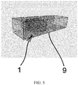
- FIGURE 5 an arrangement in accordance with at least some embodiments of the present invention is illustrated.
- an air purifier 1 as described above is arranged within a rectangular flow channel 9.
- the flow channel 9 may also be circular or elliptical, for instance.
- FIGURE 6 a honeycomb structure 2 of an air purifier 1 in accordance with at least some embodiments of the present invention is illustrated.
- a plurality of hexagonal openings 5 is provided in the honeycomb structure 2.
- the honeycomb structure 2 comprises an array of hollow openings 5 formed between very thin walls, thus forming a first grounded electrode, providing a high area through which contaminated air can pass, allowing guiding of the contaminated air flow towards the needles 4, reducing drag and allowing reduction of weight.
- FIGURE 7 different flow channels 9 of an arrangement in accordance with at least some embodiments of the present invention are illustrated.
- the flow channels 9 may have any size and shape, for example a rectangular, circular or hexagonal cross-section.
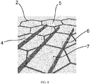
- FIGURE 8 illustrates details of an air purifier 1 in accordance with at least some embodiments of the present invention.
- the needles 4 are mounted on rails 6 downstream of the honeycomb ground plate 2. Each needle 4 is aligned with a centre of a honeycomb hexagon.
- the corona discharge spreads from the needle tips 7 to the honeycomb structure 2.
- the corona discharge covers the entire airflow facing area.
- the rails 6 are aerodynamically shaped and provide firm structure for the needles 4.
- the high ionization voltage provided by a voltage source (not shown) is supplied to the needles 4 through copper foils inside the rail material, for instance.
- At least some embodiments of the present invention find industrial application in air purifiers and/or purifying air.
- Very suitable uses being particularly flow channels, for example in hospitals, isolation rooms, operating rooms, factories manufacturing microchips as well as air intakes and/or air outlets.
Landscapes
- Engineering & Computer Science (AREA)
- Chemical & Material Sciences (AREA)
- Chemical Kinetics & Catalysis (AREA)
- General Engineering & Computer Science (AREA)
- Mechanical Engineering (AREA)
- Combustion & Propulsion (AREA)
- Health & Medical Sciences (AREA)
- General Chemical & Material Sciences (AREA)
- Public Health (AREA)
- Veterinary Medicine (AREA)
- General Health & Medical Sciences (AREA)
- Animal Behavior & Ethology (AREA)
- Life Sciences & Earth Sciences (AREA)
- Environmental & Geological Engineering (AREA)
- Epidemiology (AREA)
- Analytical Chemistry (AREA)
- Biomedical Technology (AREA)
- Oil, Petroleum & Natural Gas (AREA)
- Physics & Mathematics (AREA)
- Geometry (AREA)
- Electrostatic Separation (AREA)
- Physical Or Chemical Processes And Apparatus (AREA)
Applications Claiming Priority (1)
| Application Number | Priority Date | Filing Date | Title |
|---|---|---|---|
| FI20205494A FI130711B1 (fi) | 2020-05-15 | 2020-05-15 | Ilmanpuhdistuslaite, järjestely ja menetelmä materiaalin poistamiseksi kaasuvirrasta |
Publications (1)
| Publication Number | Publication Date |
|---|---|
| EP3909685A1 true EP3909685A1 (en) | 2021-11-17 |
Family
ID=74418189
Family Applications (1)
| Application Number | Title | Priority Date | Filing Date |
|---|---|---|---|
| EP21154185.9A Pending EP3909685A1 (en) | 2020-05-15 | 2021-01-29 | Air purifying device, arrangement and method for separating materials from a gas flow |
Country Status (13)
| Country | Link |
|---|---|
| US (1) | US20210356148A1 (pt) |
| EP (1) | EP3909685A1 (pt) |
| JP (2) | JP2021178315A (pt) |
| KR (1) | KR102535961B1 (pt) |
| CN (1) | CN113751198A (pt) |
| AU (1) | AU2021202873B2 (pt) |
| BR (1) | BR102021003312A8 (pt) |
| CA (1) | CA3109962C (pt) |
| FI (1) | FI130711B1 (pt) |
| MX (1) | MX2021005647A (pt) |
| RU (1) | RU2764693C1 (pt) |
| SG (1) | SG10202101537VA (pt) |
| ZA (1) | ZA202101105B (pt) |
Citations (6)
| Publication number | Priority date | Publication date | Assignee | Title |
|---|---|---|---|---|
| US20080034973A1 (en) * | 2004-04-22 | 2008-02-14 | Darwin Technology Limited | Device For Air Cleaning |
| CN103949343A (zh) * | 2014-05-08 | 2014-07-30 | 汉王科技股份有限公司 | 空气净化装置 |
| CN105698293A (zh) | 2016-01-28 | 2016-06-22 | 上海交通大学 | 一种多功能空气净化装置 |
| CN106861340A (zh) | 2017-03-23 | 2017-06-20 | 上海交通大学 | 一种多功能空气净化装置 |
| WO2018090990A1 (zh) | 2016-11-21 | 2018-05-24 | 深圳深亚能环保科技有限公司 | 一种具有自动清理功能的电场装置 |
| EP3552710A1 (de) * | 2018-04-10 | 2019-10-16 | BSH Hausgeräte GmbH | Elektrostatische filtereinheit und lüftungsvorrichtung mit elektrostatischer filtereinheit |
Family Cites Families (32)
| Publication number | Priority date | Publication date | Assignee | Title |
|---|---|---|---|---|
| US1344330A (en) * | 1918-10-31 | 1920-06-22 | Research Corp | Orifice-precipitator |
| GB968982A (en) * | 1959-11-20 | 1964-09-09 | Holmes & Co Ltd W C | Improved electrostatic precipitator |
| JPS54145871U (pt) * | 1978-03-31 | 1979-10-09 | ||
| SU965521A1 (ru) * | 1981-03-23 | 1982-10-15 | Магнитогорский горно-металлургический институт им.Г.И.Носова | Электрофильтр |
| SU1008830A1 (ru) * | 1981-08-14 | 1983-03-30 | Всероссийский Ордена Трудового Красного Знамени Научно-Исследовательский И Проектно-Технологический Институт Механизации И Электрификации Сельского Хозяйства | Устройство дл генерировани и перемещени ионов |
| JPS61187254U (pt) * | 1985-05-14 | 1986-11-21 | ||
| TW332802B (en) * | 1992-06-04 | 1998-06-01 | Nippon Denso Co | The air purifier |
| US6330146B1 (en) * | 1999-03-12 | 2001-12-11 | Ion Systems, Inc. | Piezoelectric/electrostrictive device and method of manufacturing same |
| GB9908099D0 (en) * | 1999-04-12 | 1999-06-02 | Gay Geoffrey N W | Air cleaning collection device |
| DE10244051C1 (de) * | 2002-09-21 | 2003-11-20 | Karlsruhe Forschzent | Ionisator und seine Verwendung in einer Abgasreinigungsanlage für tropfenbeladene und/oder kondensierende Feuchtgase |
| US7638104B2 (en) * | 2004-03-02 | 2009-12-29 | Sharper Image Acquisition Llc | Air conditioner device including pin-ring electrode configurations with driver electrode |
| DE102005023521B3 (de) * | 2005-05-21 | 2006-06-29 | Forschungszentrum Karlsruhe Gmbh | Nasselektrostatische Ionisierungsstufe in einer elektrostatischen Abscheideeinrichtung |
| US7332019B2 (en) * | 2005-08-17 | 2008-02-19 | American Standard International Inc. | Air filtration system |
| US20100282083A1 (en) * | 2007-01-03 | 2010-11-11 | John Edwards | Disinfecting air filter |
| JP4811731B2 (ja) * | 2007-02-14 | 2011-11-09 | Smc株式会社 | イオナイザ |
| US7909918B2 (en) * | 2007-08-15 | 2011-03-22 | Trane International, Inc. | Air filtration system |
| JP5125790B2 (ja) * | 2008-06-13 | 2013-01-23 | パナソニック株式会社 | 電気集じん機 |
| US20100037776A1 (en) * | 2008-08-14 | 2010-02-18 | Sik Leung Chan | Devices for removing particles from a gas comprising an electrostatic precipitator |
| RU2393022C1 (ru) * | 2009-03-17 | 2010-06-27 | Юрий Алексеевич Криштафович | Электрический очиститель воздуха |
| US8973851B2 (en) * | 2009-07-01 | 2015-03-10 | The Procter & Gamble Company | Apparatus and methods for producing charged fluid droplets |
| US8889079B2 (en) * | 2010-01-13 | 2014-11-18 | Efb, Inc. | Apparatus for removal of particles and VOC from an airstream |
| DE102010045508A1 (de) * | 2010-09-15 | 2012-03-15 | Emitec Gesellschaft Für Emissionstechnologie Mbh | Vorrichtung zur Behandlung von Rußpartikel enthaltendem Abgas |
| CN203899745U (zh) * | 2014-06-11 | 2014-10-29 | 李峰 | 六角-圆变截面通道低风阻高压静电场模块 |
| US9914134B2 (en) * | 2014-07-31 | 2018-03-13 | Trane International Inc. | Systems and methods for cleaning air |
| CN204051912U (zh) * | 2014-08-15 | 2014-12-31 | 王健 | 改良的电离净化装置 |
| CN204276154U (zh) * | 2014-08-20 | 2015-04-22 | 上海合立洁净技术工程有限公司 | 双极性尖端蜂窝状或板状组合式高压静电场装置 |
| CN104437865A (zh) * | 2014-11-24 | 2015-03-25 | 上海华兴数字科技有限公司 | 一种低臭氧静电装置及其室内空气净化器 |
| RU155104U1 (ru) * | 2015-01-23 | 2015-09-20 | федеральное государственное бюджетное образовательное учреждение высшего профессионального образования "Пермский национальный исследовательский политехнический университет" | Установка для очистки воздуха от пыли |
| CN204503330U (zh) * | 2015-02-05 | 2015-07-29 | 李峰 | 密排圆管通道针极放电静电场模块结构 |
| RU2586336C1 (ru) * | 2015-04-14 | 2016-06-10 | Алексей Алексеевич Палей | Устройство для электрической очистки газов |
| DE102018201053A1 (de) * | 2018-01-24 | 2019-07-25 | BSH Hausgeräte GmbH | Filtereinheit für Luftreinigungsvorrichtung |
| RU2742696C1 (ru) * | 2020-03-13 | 2021-02-09 | Виктор Георгиевич Карелин | Электростатический нагнетатель |
-
2020
- 2020-05-15 FI FI20205494A patent/FI130711B1/fi active
-
2021
- 2021-01-29 EP EP21154185.9A patent/EP3909685A1/en active Pending
- 2021-02-16 SG SG10202101537VA patent/SG10202101537VA/en unknown
- 2021-02-18 ZA ZA2021/01105A patent/ZA202101105B/en unknown
- 2021-02-18 RU RU2021104124A patent/RU2764693C1/ru active
- 2021-02-23 BR BR102021003312A patent/BR102021003312A8/pt unknown
- 2021-02-24 CA CA3109962A patent/CA3109962C/en active Active
- 2021-03-02 JP JP2021032315A patent/JP2021178315A/ja active Pending
- 2021-03-02 CN CN202110231210.1A patent/CN113751198A/zh active Pending
- 2021-03-12 KR KR1020210032788A patent/KR102535961B1/ko active IP Right Grant
- 2021-03-16 US US17/202,805 patent/US20210356148A1/en active Pending
- 2021-05-06 AU AU2021202873A patent/AU2021202873B2/en active Active
- 2021-05-13 MX MX2021005647A patent/MX2021005647A/es unknown
-
2023
- 2023-06-14 JP JP2023097763A patent/JP2023107942A/ja active Pending
Patent Citations (6)
| Publication number | Priority date | Publication date | Assignee | Title |
|---|---|---|---|---|
| US20080034973A1 (en) * | 2004-04-22 | 2008-02-14 | Darwin Technology Limited | Device For Air Cleaning |
| CN103949343A (zh) * | 2014-05-08 | 2014-07-30 | 汉王科技股份有限公司 | 空气净化装置 |
| CN105698293A (zh) | 2016-01-28 | 2016-06-22 | 上海交通大学 | 一种多功能空气净化装置 |
| WO2018090990A1 (zh) | 2016-11-21 | 2018-05-24 | 深圳深亚能环保科技有限公司 | 一种具有自动清理功能的电场装置 |
| CN106861340A (zh) | 2017-03-23 | 2017-06-20 | 上海交通大学 | 一种多功能空气净化装置 |
| EP3552710A1 (de) * | 2018-04-10 | 2019-10-16 | BSH Hausgeräte GmbH | Elektrostatische filtereinheit und lüftungsvorrichtung mit elektrostatischer filtereinheit |
Also Published As
| Publication number | Publication date |
|---|---|
| BR102021003312A8 (pt) | 2022-11-16 |
| FI130711B1 (fi) | 2024-02-05 |
| JP2023107942A (ja) | 2023-08-03 |
| FI20205494A1 (en) | 2021-11-16 |
| KR102535961B1 (ko) | 2023-05-26 |
| JP2021178315A (ja) | 2021-11-18 |
| SG10202101537VA (en) | 2021-12-30 |
| BR102021003312A2 (pt) | 2022-03-03 |
| CA3109962C (en) | 2023-08-29 |
| ZA202101105B (en) | 2023-03-29 |
| CN113751198A (zh) | 2021-12-07 |
| RU2764693C1 (ru) | 2022-01-19 |
| US20210356148A1 (en) | 2021-11-18 |
| MX2021005647A (es) | 2021-11-16 |
| CA3109962A1 (en) | 2021-11-15 |
| KR20210141326A (ko) | 2021-11-23 |
| AU2021202873B2 (en) | 2023-01-19 |
| AU2021202873A1 (en) | 2021-12-02 |
Similar Documents
| Publication | Publication Date | Title |
|---|---|---|
| US8690996B2 (en) | Electric precipitator and electrode plate thereof | |
| US7485174B2 (en) | Electrostatic Dust Collector | |
| KR101523209B1 (ko) | 전기집진장치 | |
| CN201688515U (zh) | 内嵌空气净化系统的空调 | |
| CN201350420Y (zh) | 一种无臭氧可清洗静电集尘器 | |
| FI125997B (en) | Electrical particle charging system and gas filtration method | |
| SE544046C2 (en) | Air purification device with a filter medium comprising a conductive material | |
| CN103752408A (zh) | 空中净化装置 | |
| EP3909685A1 (en) | Air purifying device, arrangement and method for separating materials from a gas flow | |
| JP2001121033A (ja) | 電気集塵装置 | |
| JP4983566B2 (ja) | 清浄空気製造装置 | |
| KR102504398B1 (ko) | 공기조화기용 입자 하전 장치 | |
| JP5556325B2 (ja) | 清浄空気製造装置および換気機能付清浄空気製造装置 | |
| CN111992335A (zh) | 用于过滤空气中细微颗粒物的高压集尘装置及集尘系统 | |
| CN203737396U (zh) | 空中净化装置 | |
| CN213480514U (zh) | 电净化组件、空气净化设备 | |
| US9574586B2 (en) | System and method for an electrostatic bypass | |
| CN219003375U (zh) | 一种ltp片状等离子集尘模块 | |
| CN211914193U (zh) | 用于从空气流中分离空气传播粒子的空气净化设备 | |
| EP3409372A1 (en) | Device and method for separating materials | |
| CN211914182U (zh) | 用于从空气流中分离空气传播粒子的空气净化设备 | |
| CN210373804U (zh) | 静电除尘模块和空气处理装置 | |
| JPH09173899A (ja) | 電気集塵装置 | |
| JP2835480B2 (ja) | 気体清浄装置 | |
| JP3502969B2 (ja) | 気体清浄装置用のイオン化電極の構造 |
Legal Events
| Date | Code | Title | Description |
|---|---|---|---|
| PUAI | Public reference made under article 153(3) epc to a published international application that has entered the european phase |
Free format text: ORIGINAL CODE: 0009012 |
|
| STAA | Information on the status of an ep patent application or granted ep patent |
Free format text: STATUS: THE APPLICATION HAS BEEN PUBLISHED |
|
| AK | Designated contracting states |
Kind code of ref document: A1 Designated state(s): AL AT BE BG CH CY CZ DE DK EE ES FI FR GB GR HR HU IE IS IT LI LT LU LV MC MK MT NL NO PL PT RO RS SE SI SK SM TR |
|
| B565 | Issuance of search results under rule 164(2) epc |
Effective date: 20210723 |
|
| STAA | Information on the status of an ep patent application or granted ep patent |
Free format text: STATUS: REQUEST FOR EXAMINATION WAS MADE |
|
| 17P | Request for examination filed |
Effective date: 20220513 |
|
| RBV | Designated contracting states (corrected) |
Designated state(s): AL AT BE BG CH CY CZ DE DK EE ES FI FR GB GR HR HU IE IS IT LI LT LU LV MC MK MT NL NO PL PT RO RS SE SI SK SM TR |
|
| GRAP | Despatch of communication of intention to grant a patent |
Free format text: ORIGINAL CODE: EPIDOSNIGR1 |
|
| STAA | Information on the status of an ep patent application or granted ep patent |
Free format text: STATUS: GRANT OF PATENT IS INTENDED |
|
| RIC1 | Information provided on ipc code assigned before grant |
Ipc: B03C 3/47 20060101ALI20240124BHEP Ipc: B03C 3/08 20060101ALI20240124BHEP Ipc: B03C 3/12 20060101ALI20240124BHEP Ipc: B03C 3/41 20060101AFI20240124BHEP |
|
| INTG | Intention to grant announced |
Effective date: 20240215 |
|
| RIN1 | Information on inventor provided before grant (corrected) |
Inventor name: SKOGSTER, NIKLAS Inventor name: MAKKONEN, PASI Inventor name: TULKKI, JUHANI |
|
| GRAS | Grant fee paid |
Free format text: ORIGINAL CODE: EPIDOSNIGR3 |
|
| GRAA | (expected) grant |
Free format text: ORIGINAL CODE: 0009210 |
|
| STAA | Information on the status of an ep patent application or granted ep patent |
Free format text: STATUS: THE PATENT HAS BEEN GRANTED |