EP3902106A1 - Glue lamination core and method for manufacturing same, and rotating electrical machine - Google Patents
Glue lamination core and method for manufacturing same, and rotating electrical machine Download PDFInfo
- Publication number
- EP3902106A1 EP3902106A1 EP19898326.4A EP19898326A EP3902106A1 EP 3902106 A1 EP3902106 A1 EP 3902106A1 EP 19898326 A EP19898326 A EP 19898326A EP 3902106 A1 EP3902106 A1 EP 3902106A1
- Authority
- EP
- European Patent Office
- Prior art keywords
- electrical steel
- adhesively
- inorganic filler
- laminated core
- particle size
- Prior art date
- Legal status (The legal status is an assumption and is not a legal conclusion. Google has not performed a legal analysis and makes no representation as to the accuracy of the status listed.)
- Granted
Links
Images


Classifications
-
- H—ELECTRICITY
- H01—ELECTRIC ELEMENTS
- H01F—MAGNETS; INDUCTANCES; TRANSFORMERS; SELECTION OF MATERIALS FOR THEIR MAGNETIC PROPERTIES
- H01F27/00—Details of transformers or inductances, in general
- H01F27/24—Magnetic cores
- H01F27/245—Magnetic cores made from sheets, e.g. grain-oriented
-
- H—ELECTRICITY
- H02—GENERATION; CONVERSION OR DISTRIBUTION OF ELECTRIC POWER
- H02K—DYNAMO-ELECTRIC MACHINES
- H02K1/00—Details of the magnetic circuit
- H02K1/06—Details of the magnetic circuit characterised by the shape, form or construction
- H02K1/22—Rotating parts of the magnetic circuit
- H02K1/28—Means for mounting or fastening rotating magnetic parts on to, or to, the rotor structures
-
- B—PERFORMING OPERATIONS; TRANSPORTING
- B32—LAYERED PRODUCTS
- B32B—LAYERED PRODUCTS, i.e. PRODUCTS BUILT-UP OF STRATA OF FLAT OR NON-FLAT, e.g. CELLULAR OR HONEYCOMB, FORM
- B32B15/00—Layered products comprising a layer of metal
- B32B15/04—Layered products comprising a layer of metal comprising metal as the main or only constituent of a layer, which is next to another layer of the same or of a different material
- B32B15/043—Layered products comprising a layer of metal comprising metal as the main or only constituent of a layer, which is next to another layer of the same or of a different material of metal
-
- B—PERFORMING OPERATIONS; TRANSPORTING
- B32—LAYERED PRODUCTS
- B32B—LAYERED PRODUCTS, i.e. PRODUCTS BUILT-UP OF STRATA OF FLAT OR NON-FLAT, e.g. CELLULAR OR HONEYCOMB, FORM
- B32B15/00—Layered products comprising a layer of metal
- B32B15/18—Layered products comprising a layer of metal comprising iron or steel
-
- B—PERFORMING OPERATIONS; TRANSPORTING
- B32—LAYERED PRODUCTS
- B32B—LAYERED PRODUCTS, i.e. PRODUCTS BUILT-UP OF STRATA OF FLAT OR NON-FLAT, e.g. CELLULAR OR HONEYCOMB, FORM
- B32B7/00—Layered products characterised by the relation between layers; Layered products characterised by the relative orientation of features between layers, or by the relative values of a measurable parameter between layers, i.e. products comprising layers having different physical, chemical or physicochemical properties; Layered products characterised by the interconnection of layers
- B32B7/04—Interconnection of layers
- B32B7/12—Interconnection of layers using interposed adhesives or interposed materials with bonding properties
- B32B7/14—Interconnection of layers using interposed adhesives or interposed materials with bonding properties applied in spaced arrangements, e.g. in stripes
-
- C—CHEMISTRY; METALLURGY
- C08—ORGANIC MACROMOLECULAR COMPOUNDS; THEIR PREPARATION OR CHEMICAL WORKING-UP; COMPOSITIONS BASED THEREON
- C08G—MACROMOLECULAR COMPOUNDS OBTAINED OTHERWISE THAN BY REACTIONS ONLY INVOLVING UNSATURATED CARBON-TO-CARBON BONDS
- C08G59/00—Polycondensates containing more than one epoxy group per molecule; Macromolecules obtained by polymerising compounds containing more than one epoxy group per molecule using curing agents or catalysts which react with the epoxy groups
- C08G59/18—Macromolecules obtained by polymerising compounds containing more than one epoxy group per molecule using curing agents or catalysts which react with the epoxy groups ; e.g. general methods of curing
- C08G59/40—Macromolecules obtained by polymerising compounds containing more than one epoxy group per molecule using curing agents or catalysts which react with the epoxy groups ; e.g. general methods of curing characterised by the curing agents used
- C08G59/62—Alcohols or phenols
- C08G59/621—Phenols
-
- C—CHEMISTRY; METALLURGY
- C09—DYES; PAINTS; POLISHES; NATURAL RESINS; ADHESIVES; COMPOSITIONS NOT OTHERWISE PROVIDED FOR; APPLICATIONS OF MATERIALS NOT OTHERWISE PROVIDED FOR
- C09J—ADHESIVES; NON-MECHANICAL ASPECTS OF ADHESIVE PROCESSES IN GENERAL; ADHESIVE PROCESSES NOT PROVIDED FOR ELSEWHERE; USE OF MATERIALS AS ADHESIVES
- C09J11/00—Features of adhesives not provided for in group C09J9/00, e.g. additives
- C09J11/02—Non-macromolecular additives
- C09J11/04—Non-macromolecular additives inorganic
-
- C—CHEMISTRY; METALLURGY
- C09—DYES; PAINTS; POLISHES; NATURAL RESINS; ADHESIVES; COMPOSITIONS NOT OTHERWISE PROVIDED FOR; APPLICATIONS OF MATERIALS NOT OTHERWISE PROVIDED FOR
- C09J—ADHESIVES; NON-MECHANICAL ASPECTS OF ADHESIVE PROCESSES IN GENERAL; ADHESIVE PROCESSES NOT PROVIDED FOR ELSEWHERE; USE OF MATERIALS AS ADHESIVES
- C09J163/00—Adhesives based on epoxy resins; Adhesives based on derivatives of epoxy resins
-
- C—CHEMISTRY; METALLURGY
- C09—DYES; PAINTS; POLISHES; NATURAL RESINS; ADHESIVES; COMPOSITIONS NOT OTHERWISE PROVIDED FOR; APPLICATIONS OF MATERIALS NOT OTHERWISE PROVIDED FOR
- C09J—ADHESIVES; NON-MECHANICAL ASPECTS OF ADHESIVE PROCESSES IN GENERAL; ADHESIVE PROCESSES NOT PROVIDED FOR ELSEWHERE; USE OF MATERIALS AS ADHESIVES
- C09J163/00—Adhesives based on epoxy resins; Adhesives based on derivatives of epoxy resins
- C09J163/10—Epoxy resins modified by unsaturated compounds
-
- H—ELECTRICITY
- H01—ELECTRIC ELEMENTS
- H01F—MAGNETS; INDUCTANCES; TRANSFORMERS; SELECTION OF MATERIALS FOR THEIR MAGNETIC PROPERTIES
- H01F3/00—Cores, Yokes, or armatures
- H01F3/02—Cores, Yokes, or armatures made from sheets
-
- H—ELECTRICITY
- H01—ELECTRIC ELEMENTS
- H01F—MAGNETS; INDUCTANCES; TRANSFORMERS; SELECTION OF MATERIALS FOR THEIR MAGNETIC PROPERTIES
- H01F41/00—Apparatus or processes specially adapted for manufacturing or assembling magnets, inductances or transformers; Apparatus or processes specially adapted for manufacturing materials characterised by their magnetic properties
- H01F41/02—Apparatus or processes specially adapted for manufacturing or assembling magnets, inductances or transformers; Apparatus or processes specially adapted for manufacturing materials characterised by their magnetic properties for manufacturing cores, coils, or magnets
-
- H—ELECTRICITY
- H01—ELECTRIC ELEMENTS
- H01F—MAGNETS; INDUCTANCES; TRANSFORMERS; SELECTION OF MATERIALS FOR THEIR MAGNETIC PROPERTIES
- H01F41/00—Apparatus or processes specially adapted for manufacturing or assembling magnets, inductances or transformers; Apparatus or processes specially adapted for manufacturing materials characterised by their magnetic properties
- H01F41/02—Apparatus or processes specially adapted for manufacturing or assembling magnets, inductances or transformers; Apparatus or processes specially adapted for manufacturing materials characterised by their magnetic properties for manufacturing cores, coils, or magnets
- H01F41/0206—Manufacturing of magnetic cores by mechanical means
- H01F41/0233—Manufacturing of magnetic circuits made from sheets
-
- H—ELECTRICITY
- H02—GENERATION; CONVERSION OR DISTRIBUTION OF ELECTRIC POWER
- H02K—DYNAMO-ELECTRIC MACHINES
- H02K1/00—Details of the magnetic circuit
- H02K1/04—Details of the magnetic circuit characterised by the material used for insulating the magnetic circuit or parts thereof
-
- H—ELECTRICITY
- H02—GENERATION; CONVERSION OR DISTRIBUTION OF ELECTRIC POWER
- H02K—DYNAMO-ELECTRIC MACHINES
- H02K1/00—Details of the magnetic circuit
- H02K1/06—Details of the magnetic circuit characterised by the shape, form or construction
- H02K1/12—Stationary parts of the magnetic circuit
- H02K1/18—Means for mounting or fastening magnetic stationary parts on to, or to, the stator structures
-
- H—ELECTRICITY
- H02—GENERATION; CONVERSION OR DISTRIBUTION OF ELECTRIC POWER
- H02K—DYNAMO-ELECTRIC MACHINES
- H02K1/00—Details of the magnetic circuit
- H02K1/06—Details of the magnetic circuit characterised by the shape, form or construction
- H02K1/22—Rotating parts of the magnetic circuit
- H02K1/28—Means for mounting or fastening rotating magnetic parts on to, or to, the rotor structures
- H02K1/30—Means for mounting or fastening rotating magnetic parts on to, or to, the rotor structures using intermediate parts, e.g. spiders
-
- H—ELECTRICITY
- H02—GENERATION; CONVERSION OR DISTRIBUTION OF ELECTRIC POWER
- H02K—DYNAMO-ELECTRIC MACHINES
- H02K15/00—Processes or apparatus specially adapted for manufacturing, assembling, maintaining or repairing of dynamo-electric machines
- H02K15/02—Processes or apparatus specially adapted for manufacturing, assembling, maintaining or repairing of dynamo-electric machines of stator or rotor bodies
-
- B—PERFORMING OPERATIONS; TRANSPORTING
- B21—MECHANICAL METAL-WORKING WITHOUT ESSENTIALLY REMOVING MATERIAL; PUNCHING METAL
- B21D—WORKING OR PROCESSING OF SHEET METAL OR METAL TUBES, RODS OR PROFILES WITHOUT ESSENTIALLY REMOVING MATERIAL; PUNCHING METAL
- B21D28/00—Shaping by press-cutting; Perforating
- B21D28/02—Punching blanks or articles with or without obtaining scrap; Notching
- B21D28/22—Notching the peripheries of circular blanks, e.g. laminations for dynamo-electric machines
-
- B—PERFORMING OPERATIONS; TRANSPORTING
- B32—LAYERED PRODUCTS
- B32B—LAYERED PRODUCTS, i.e. PRODUCTS BUILT-UP OF STRATA OF FLAT OR NON-FLAT, e.g. CELLULAR OR HONEYCOMB, FORM
- B32B2250/00—Layers arrangement
- B32B2250/05—5 or more layers
-
- B—PERFORMING OPERATIONS; TRANSPORTING
- B32—LAYERED PRODUCTS
- B32B—LAYERED PRODUCTS, i.e. PRODUCTS BUILT-UP OF STRATA OF FLAT OR NON-FLAT, e.g. CELLULAR OR HONEYCOMB, FORM
- B32B2255/00—Coating on the layer surface
- B32B2255/06—Coating on the layer surface on metal layer
-
- B—PERFORMING OPERATIONS; TRANSPORTING
- B32—LAYERED PRODUCTS
- B32B—LAYERED PRODUCTS, i.e. PRODUCTS BUILT-UP OF STRATA OF FLAT OR NON-FLAT, e.g. CELLULAR OR HONEYCOMB, FORM
- B32B2255/00—Coating on the layer surface
- B32B2255/20—Inorganic coating
-
- B—PERFORMING OPERATIONS; TRANSPORTING
- B32—LAYERED PRODUCTS
- B32B—LAYERED PRODUCTS, i.e. PRODUCTS BUILT-UP OF STRATA OF FLAT OR NON-FLAT, e.g. CELLULAR OR HONEYCOMB, FORM
- B32B2255/00—Coating on the layer surface
- B32B2255/26—Polymeric coating
-
- B—PERFORMING OPERATIONS; TRANSPORTING
- B32—LAYERED PRODUCTS
- B32B—LAYERED PRODUCTS, i.e. PRODUCTS BUILT-UP OF STRATA OF FLAT OR NON-FLAT, e.g. CELLULAR OR HONEYCOMB, FORM
- B32B2255/00—Coating on the layer surface
- B32B2255/28—Multiple coating on one surface
-
- B—PERFORMING OPERATIONS; TRANSPORTING
- B32—LAYERED PRODUCTS
- B32B—LAYERED PRODUCTS, i.e. PRODUCTS BUILT-UP OF STRATA OF FLAT OR NON-FLAT, e.g. CELLULAR OR HONEYCOMB, FORM
- B32B2307/00—Properties of the layers or laminate
- B32B2307/20—Properties of the layers or laminate having particular electrical or magnetic properties, e.g. piezoelectric
- B32B2307/202—Conductive
-
- B—PERFORMING OPERATIONS; TRANSPORTING
- B32—LAYERED PRODUCTS
- B32B—LAYERED PRODUCTS, i.e. PRODUCTS BUILT-UP OF STRATA OF FLAT OR NON-FLAT, e.g. CELLULAR OR HONEYCOMB, FORM
- B32B2307/00—Properties of the layers or laminate
- B32B2307/20—Properties of the layers or laminate having particular electrical or magnetic properties, e.g. piezoelectric
- B32B2307/208—Magnetic, paramagnetic
-
- B—PERFORMING OPERATIONS; TRANSPORTING
- B32—LAYERED PRODUCTS
- B32B—LAYERED PRODUCTS, i.e. PRODUCTS BUILT-UP OF STRATA OF FLAT OR NON-FLAT, e.g. CELLULAR OR HONEYCOMB, FORM
- B32B2457/00—Electrical equipment
-
- H—ELECTRICITY
- H02—GENERATION; CONVERSION OR DISTRIBUTION OF ELECTRIC POWER
- H02K—DYNAMO-ELECTRIC MACHINES
- H02K2213/00—Specific aspects, not otherwise provided for and not covered by codes H02K2201/00 - H02K2211/00
- H02K2213/03—Machines characterised by numerical values, ranges, mathematical expressions or similar information
-
- Y—GENERAL TAGGING OF NEW TECHNOLOGICAL DEVELOPMENTS; GENERAL TAGGING OF CROSS-SECTIONAL TECHNOLOGIES SPANNING OVER SEVERAL SECTIONS OF THE IPC; TECHNICAL SUBJECTS COVERED BY FORMER USPC CROSS-REFERENCE ART COLLECTIONS [XRACs] AND DIGESTS
- Y02—TECHNOLOGIES OR APPLICATIONS FOR MITIGATION OR ADAPTATION AGAINST CLIMATE CHANGE
- Y02T—CLIMATE CHANGE MITIGATION TECHNOLOGIES RELATED TO TRANSPORTATION
- Y02T10/00—Road transport of goods or passengers
- Y02T10/60—Other road transportation technologies with climate change mitigation effect
- Y02T10/64—Electric machine technologies in electromobility
Definitions
- the present invention relates to an adhesively-laminated core, a manufacturing method thereof, and an electric motor.
- an adhesively-laminated core used in motors, transformers, and the like is known.
- the adhesively-laminated core has a configuration in which a plurality of thin electrical steel sheets are stacked and are integrated with each other by an adhesive.
- the adhesively-laminated core having poor flatness the adhesively-laminated core may not stand upright, the adhesively-laminated core may be tilted, the accuracy of the adhesively-laminated core may not be stable, and magnetic properties of the adhesively-laminated core may deteriorate.
- Patent Document 1 proposes an adhesively-laminated core in which electrical steel sheets are adhered to each other by an adhesive containing an epoxy resin and a rubber component and the amount of the adhesive squeezed out from the outer peripheral portion of the electrical steel sheet is suppressed.
- the adhesively-laminated core of Patent Document 1 attempts to improve the accuracy of the film thickness of the adhesion part.
- Patent Document 1 Japanese Unexamined Patent Application, First Publication No. 2014-096429
- the present invention has been made in view of the above-described circumstances and an object of the present invention is to provide an adhesively-laminated core capable of further improving flatness and improving space factor, a manufacturing method thereof, and an electric motor.
- the expansion or contraction of the adhesion part can be suppressed when an inorganic filler is blended with the adhesion part for adhering the electrical steel sheets to each other.
- An increase in the space factor of the adhesively-laminated core means an increase in the ratio of the electrical steel sheet in the cross-section of the adhesively-laminated core in the stacking direction. This means that the magnetic field lines can be formed at a high density when the magnetic field lines are generated inside the adhesively-laminated core by excitation from the winding current. That is, an increase in the space factor of the adhesively-laminated core means the improvement of magnetic properties of the adhesively-laminated core.
- the adhesively-laminated core can easily stand up, can be easily flattened, and increase the space factor.
- the present inventors have found that the flatness of the adhesively-laminated core is determined not only by the 50% particle size (the center particle size) of the inorganic filler or the average particle size of the inorganic filler (the arithmetic mean of the particle size of all particles of the inorganic filler) but also by the 90% particle size of the inorganic filler or the maximum particle size of the inorganic filler. That is, the present inventors have found that the flatness of the adhesively-laminated core is determined by a component having a large particle size in the population of particles of the inorganic filler.
- the coarse particles dominate the gaps between the electrical steel sheets when the "coarse particles" are present in the population of inorganic filler particles even when the 50% particle size or the average particle size of the inorganic filler is small.
- the present inventors have carried out careful examination in order to solve the above-described problems. As a result, the present inventors have found that the flatness of the adhesively-laminated core can be further improved and the space factor of the adhesively-laminated core can be improved by decreasing the 50% particle size of the inorganic filler contained in the adhesion part and decreasing the 90% particle size of the inorganic filler contained in the adhesion part and completed the present invention.
- the present invention has the following aspects.
- the adhesively-laminated core of the present invention it is possible to further improve flatness and to improve space factor.
- an adhesively-laminated core according to an embodiment of the present invention and an electric motor including the adhesively-laminated core will be described with reference to the drawings.
- an electric motor as a motor specifically, an AC motor, more specifically, a synchronous motor, and even more specifically, a permanent magnetic electric motor will be described as an example.
- Such a motor is suitably used in, for example, an electric vehicle or the like.
- an electric motor 10 includes a stator 20, a rotor 30, a casing 50, and a rotation shaft 60.
- the stator 20 and the rotor 30 are accommodated in the casing 50.
- the stator 20 is fixed to the casing 50.
- the electric motor 10 is of an inner rotor type in which the rotor 30 is located on the inside of the stator 20.
- the electric motor 10 may be of an outer rotor type in which the rotor 30 is located on the outside of the stator 20.
- the electric motor 10 is a 12-pole and 18-slot three-phase AC motor.
- the number of poles, the number of slots, the number of phases, and the like can be changed as appropriate.
- the electric motor 10 can rotate at a rotation speed of 1000 rpm, for example, by applying an excitation current having an effective value of 10 A and a frequency of 100 Hz to each phase.
- the stator 20 includes a stator core 21 and a winding (not shown).
- the stator core 21 includes an annular core back part 22 and a plurality of tooth parts 23.
- the direction of the center axis O of the stator core 21 (or the core back part 22) is referred to as the axial direction
- the radial direction (the direction orthogonal to the center axis O) of the stator core 21 (or the core back part 22)
- the circumferential direction (the direction to orbit around the center axis O) of the stator core 21 (or the core back part 22) is referred to as the circumferential direction.
- the core back part 22 is formed in an annular ring shape in a plan view when the stator 20 is viewed from the axial direction.
- the plurality of tooth parts 23 protrude from the core back part 22 inward in the radial direction (toward the center axis O of the core back part 22 in the radial direction).
- the plurality of tooth parts 23 are arranged at equal intervals in the circumferential direction.
- eighteen tooth parts 23 are provided at the intervals of the center angles of 20° around the center axis O.
- the plurality of tooth parts 23 are formed to have the same shape and the same size.
- the winding is wound around the tooth part 23.
- the winding may be a concentrated winding or a distributed winding.
- the rotor 30 is disposed on the inside of the radial direction with respect to the stator 20 (or the stator core 21).
- the rotor 30 includes a rotor core 31 and a plurality of permanent magnets 32.
- the rotor core 31 is formed in an annular shape (annular ring shape) to be arranged coaxially with the stator 20.
- the rotation shaft 60 is disposed inside the rotor core 31.
- the rotation shaft 60 is fixed to the rotor core 31.
- the plurality of permanent magnets 32 are fixed to the rotor core 31.
- a set of two permanent magnets 32 forms one magnetic pole.
- a plurality of sets of permanent magnets 32 are arranged at equal intervals in the circumferential direction. In this embodiment, twelve sets (twenty four in total) of permanent magnets 32 are provided at the intervals of the center angles of 30° around the center axis O.
- an interior permanent magnet motor is employed as the permanent magnetic electric motor.
- a plurality of through holes 33 penetrating the rotor core 31 in the axial direction are formed in the rotor core 31.
- the plurality of through holes 33 are provided to correspond to the plurality of permanent magnets 32.
- Each permanent magnet 32 is fixed to the rotor core 31 while being disposed inside the corresponding through hole 33.
- Each permanent magnet 32 can be fixed to the rotor core 31, for example, in such a manner that the outer surface of the permanent magnet 32 and the inner surface of the through hole 33 are adhered to each other by an adhesive.
- a surface permanent magnet motor may be used instead of the interior permanent magnet motor.
- both the stator core 21 and the rotor core 31 are adhesively-laminated cores.
- the stator 20 is formed by stacking a plurality of electrical steel sheets 40.
- an adhesion part 41 for adhering these electrical steel sheets 40 is provided between the electrical steel sheets 40 which are adjacent to each other in the stacking direction and the electrical steel sheets 40 are adhered to each other by the adhesion part 41. That is, in the stator 20, the plurality of electrical steel sheets 40 forming the stator core 21 are stacked with the adhesion part 41 interposed therebetween.
- the lamination thickness of each of the stator core 21 and the rotor core 31 is, for example, 50.0 mm.
- the outer diameter of the stator core 21 is, for example, 250.0 mm.
- the inner diameter of the stator core 21 is, for example, 165.0 mm.
- the outer diameter of the rotor core 31 is, for example, 163.0 mm.
- the inner diameter of the rotor core 31 is, for example, 30.0 mm.
- these values are examples, and the lamination thickness, outer diameter, or inner diameter of the stator core 21 and the lamination thickness, outer diameter, or inner diameter of the rotor core 31 are not limited to these values.
- the inner diameter of the stator core 21 is based on the tip of the tooth part 23 of the stator core 21.
- the inner diameter of the stator core 21 is the diameter of the virtual circle inscribed in the tips of all tooth parts 23.
- Each of the electrical steel sheets 40 forming the stator core 21 and the rotor core 31 is formed, for example, by punching an electrical steel sheet as a base material.
- a known electrical steel sheet can be used for the electrical steel sheet 40.
- the chemical composition of the electrical steel sheet 40 is not particularly limited.
- a non-grain-oriented electrical steel sheet is employed as the electrical steel sheet 40.
- a non-grain-oriented electrical steel strip of JIS C 2552: 2014 can be employed as the non-grain-oriented electrical steel strip of JIS C 2552: 2014 can be employed.
- a grain-oriented electrical steel sheet can be employed instead of the non-grain-oriented electrical steel sheet.
- a grain-oriented electrical steel strip of JIS C 2553: 2012 can be employed.
- an insulation coating is provided on both surfaces of the electrical steel sheet 40.
- a material constituting the insulation coating for example, (1) an inorganic compound, (2) an organic resin, (3) a mixture of an inorganic compound and an organic resin, and the like can be applied.
- the inorganic compound include (1) a complex of dichromate and boric acid, (2) a complex of phosphate and silica, (3) phosphate, and the like.
- the organic resin include an epoxy resin, an acrylic resin, an acrylic styrene resin, a polyester resin, a silicone resin, a fluororesin, and the like.
- the organic resin may be the same as or different from the organic resin contained in the adhesive described later.
- the thickness of the insulation coating is preferably 0.1 ⁇ m or more.
- the insulation effect becomes saturated as the insulation coating becomes thick. Further, as the insulation coating becomes thick, a space factor decreases and the performance as the adhesively-laminated core decreases.
- the insulating coating should be as thin as possible in the range capable of ensuring the insulation performance.
- the thickness of the insulation coating (the thickness per one side of the electrical steel sheet 40) is preferably 0.1 ⁇ m or more and 5 ⁇ m or less.
- the thickness of the insulation coating is more preferably 0.1 ⁇ m or more and 2 ⁇ m or less.
- the thickness of the insulation coating can be measured, for example, by observing the cut surface of the electrical steel sheet 40 cut in the thickness direction with a microscope or the like.
- the thickness of the electrical steel sheet 40 is preferably 0.10 mm or more in consideration of the iron loss improvement effect and the manufacturing cost.
- the thickness of the electrical steel sheet 40 is preferably 0.65 mm or less in consideration of the press punching work of the electrical steel sheet 40.
- the thickness of the electrical steel sheet 40 is preferably 0.35 mm or less, more preferably 0.25 mm or less, and even more preferably 0.20 mm or less in consideration of the iron loss characteristics of the electrical steel sheet 40.
- each electrical steel sheet 40 is, for example, preferably 0.10 mm or more and 0.65 mm or less, more preferably 0.10 mm or more and 0.35 mm or less, even more preferably 0.10 mm or more and 0.25 mm or less, and particularly preferably 0.10 mm or more and 0.20 mm or less. Further, the thickness of the electrical steel sheet 40 also includes the thickness of the insulation coating.
- the thickness of the electrical steel sheet 40 can be measured by, for example, a micrometer or the like.
- the plurality of electrical steel sheets 40 forming the stator core 21 are stacked with the adhesion part 41 interposed therebetween.
- the adhesion part 41 is formed in the core back part 22 and the tooth part 23 of the stator core 21.
- the adhesion part 41 is formed from the inner periphery of the core back part 22 inward in the radial direction (toward the center axis O of the core back part 22 in the radial direction) as adhesion parts 41a, 41b, and 41c.
- the plurality of tooth parts 23 are respectively provided with the adhesion parts 41b and 41c.
- the adhesion part 41a is formed in each of the core back part 22 at a position corresponding to the plurality of tooth parts 23.
- the adhesion part 41 is a layer which is formed by an adhesive containing an organic resin and an inorganic filler.
- the organic resin constituting the adhesive is not particularly limited and examples thereof include a polyolefin resin, an acrylic resin, a polyurethane resin, an epoxy resin, a polyamide resin, a polyimide resin, a polyester resin, a silicone resin, and a fluororesin.
- an acrylic modified epoxy resin obtained by graft-polymerizing an acrylic resin on an epoxy resin is preferable from the viewpoint of easily increasing the adhesion strength of the adhesion part 41.
- the epoxy resin examples include those obtained by condensing epichlorohydrin and bisphenol in the presence of an alkaline catalyst, those obtained by condensing epichlorohydrin and bisphenol into a low molecular weight epoxy resin in the presence of an alkaline catalyst and subjecting the low molecular weight epoxy resin and bisphenol to a polyaddition reaction, and the like.
- the "low molecular weight epoxy resin” means an epoxy resin having a number average molecular weight smaller than 1200.
- the epoxy resin may be an epoxy ester resin in which a divalent carboxylic acid is combined.
- divalent carboxylic acid include succinic acid, adipic acid, pimelic acid, azelaic acid, sebacic acid, dodecanedioic acid, hexahydrophthalic acid and the like.
- bisphenol examples include bisphenol A, bisphenol F, bisphenol AD, and the like, and bisphenol A and bisphenol F are preferable.
- alkaline catalyst examples include sodium hydroxide, potassium hydroxide, and the like.
- One type of these epoxy resins may be used alone or two or more types may be used in combination.
- the number average molecular weight of the epoxy resin is preferably 1200 to 8000, more preferably 2000 to 7000, and even more preferably 2500 to 7000.
- the number average molecular weight of the epoxy resin is equal to or larger than the lower limit value, it is easy to increase the adhesion strength of the adhesion part 41.
- the number average molecular weight of the epoxy resin is equal to or smaller than the upper limit value, it is easy to increase the stability of the adhesion part 41.
- the number average molecular weight of the epoxy resin can be measured by size-exclusion chromatography (SEC) described in JIS K 7252-1: 2008 using polystyrene as a standard substance.
- the amount of the epoxy resin is, for example, preferably 30 to 90% by mass, more preferably 40 to 80% by mass, and even more preferably 50 to 70% by mass with respect to the total mass of the adhesive.
- the amount of the epoxy resin is equal to or larger than the lower limit value, it is easy to increase the adhesion strength of the adhesion part 41.
- the amount of the epoxy resin is equal to or smaller than the upper limit value, it is easy to alleviate the strain generated in the electrical steel sheet 40.
- acrylic resin examples include an acrylic resin obtained by polymerizing or copolymerizing at least one selected from unsaturated carboxylic acids such as acrylic acid, methacrylic acid, maleic acid, itaconic acid, and crotonic acid, an acrylic resin obtained by copolymerizing at least one monomer selected from the unsaturated carboxylic acids and at least one selected from the following radically polymerizable unsaturated monomers, and the like.
- unsaturated carboxylic acids such as acrylic acid, methacrylic acid, maleic acid, itaconic acid, and crotonic acid
- acrylic resin obtained by copolymerizing at least one monomer selected from the unsaturated carboxylic acids and at least one selected from the following radically polymerizable unsaturated monomers and the like.
- Examples of the radically polymerizable unsaturated monomers include (1) hydroxyalkyl esters of acrylic acid or methacrylic acid with 1 to 8 carbon atoms, such as 2-hydroxyethyl acrylate, 2-hydroxyethyl methacrylate, hydroxypropyl acrylate, and hydroxypropyl methacrylate, (2) alkyl esters or cycloalkyl esters of acrylic acid or methacrylic acid with 1 to 24 carbon atoms, such as methyl acrylate, methyl methacrylate, ethyl acrylate, ethyl methacrylate, n-butyl acrylate, n-butyl methacrylate, isobutyl acrylate, isobutyl methacrylate, tert-butyl acrylate, tert-butyl methacrylate, cyclohexyl acrylate, cyclohexyl methacrylate, 2-ethylhexyl acrylate, 2-ethy
- Preferred combinations of the above unsaturated monomers include, for example, a combination of methyl methacrylate, 2-ethylhexyl acrylate, and acrylic acid, a combination of styrene, methyl methacrylate, ethyl acrylate, and methacrylic acid, a combination of styrene, ethyl acrylate, and methacrylic acid, a combination of methyl methacrylate, ethyl acrylate, and acrylic acid, and the like.
- the number average molecular weight of the acrylic resin is preferably 5,000 to 100,000, more preferably 6,000 to 80,000, and even more preferably 7,000 to 60,000.
- the number average molecular weight of the acrylic resin is equal to or larger than the lower limit value, it is easy to increase the adhesion strength of the adhesion part 41.
- the number average molecular weight of the acrylic resin is equal to or smaller than the upper limit value, it is easy to suppress the high viscosity of the adhesive and to flatten the adhesion part 41.
- the number average molecular weight of the acrylic resin can be measured by the same method as the number average molecular weight of the epoxy resin.
- the amount of the acrylic resin is, for example, preferably 10 to 40% by mass, more preferably 15 to 35% by mass, and even more preferably 20 to 30% by mass with respect to the total mass of the adhesive.
- the amount of the acrylic resin is equal to or larger than the lower limit value, it is easy to increase the adhesion strength of the adhesion part 41.
- the amount of the acrylic resin is equal to or smaller than the upper limit value, it is easy to suppress the high viscosity of the adhesive and to flatten the adhesion part 41. Therefore, it is easy to suppress the strain of the adhesively-laminated core.
- An acrylic modified epoxy resin obtained, for example, by graft-polymerizing an acrylic resin on an epoxy resin can be obtained by subjecting the above-described radically polymerizable unsaturated monomer to a graft polymerization reaction on a high molecular weight epoxy resin in the presence of a radical generator such as benzoyl peroxide in an organic solvent solution.
- a radical generator such as benzoyl peroxide
- the "high molecular weight epoxy resin” means an epoxy resin having a number average molecular weight of 1200 or more.
- the radical generator used in the graft polymerization reaction is preferably 3 to 15 parts by mass with respect to 100 parts by mass of the solid content of the radically polymerizable unsaturated monomer.
- the graft polymerization reaction can be performed, for example, by adding a radically polymerizable unsaturated monomer, which is uniformly mixed with a radical generator, to an organic solvent solution of a high molecular weight epoxy resin heated at 80 to 150°C over 1 to 3 hours and maintaining the temperature over 1 to 3 hours.
- the organic solvent used in the graft polymerization reaction may be any organic solvent that dissolves the high molecular weight epoxy resin and the radically polymerizable unsaturated monomer and can be mixed with water.
- organic solvent examples include alcohol solvent such as isopropanol, butyl alcohol, 2-hydroxy-4-methylpentane, 2-ethylhexyl alcohol, cyclohexanol, ethylene glycol, diethylene glycol, 1,3-butylene glycol, ethylene glycol monoethyl ether, ethylene glycol monobutyl ether, and diethylene glycol monomethyl ether, ketone solvent such as acetone and methyl ethyl ketone, cellosolve solvent, and carbitol solvent.
- alcohol solvent such as isopropanol, butyl alcohol, 2-hydroxy-4-methylpentane, 2-ethylhexyl alcohol, cyclohexanol, ethylene glycol, diethylene glycol, 1,3-butylene glycol, ethylene glycol monoethyl ether, ethylene glycol monobutyl ether, and diethylene glycol monomethyl ether
- ketone solvent such as acetone and methyl ethyl
- an inert organic solvent that is immiscible with water can also be used and examples of such an organic solvent include aromatic hydrocarbons such as toluene and xylene, and esters such as ethyl acetate and butyl acetate.
- the curing agent can be a commonly used epoxy resin curing agent.
- the epoxy resin curing agent for example, at least one selected from polyamine-based curing agents such as aliphatic polyamines, alicyclic polyamines, aromatic polyamines, polyamide polyamines, and modified polyamines; acid anhydride-based curing agents such as monofunctional acid anhydride (phthalic anhydride, hexahydrophthalic anhydride, methyltetrahydrophthalic anhydride, methylhexahydrophthalic anhydride, methylnadic anhydride, chlorendic anhydride, and the like), bifunctional acid anhydrides (pyromellitic anhydride, benzophenone tetracarboxylic acid anhydride, ethylene glycol bis(anhydrotrimate), methylcyclohexenetetracarboxylic acid anhydride, and the like), and free acid anhydride (trimellitic anhydride, polyazelaic anhydride,
- latent curing agent examples include dicyandiamide, melamine, organic acid dihydrazide, amineimide, ketimine, tertiary amine, imidazole salt, boron trifluoride amine salt, a microcapsule type curing agent (a substance in which a curing agent is encapsulated in microcapsules formed of casein or the like and the microcapsules are broken by heating and pressurizing to perform a curing reaction with a resin), a molecular sieve type curing agent (a substance in which a curing agent is adsorbed on the surface of an adsorptive compound, which releases adsorbed molecules by heating and undergoes a curing reaction with a resin), and the like.
- a microcapsule type curing agent a substance in which a curing agent is encapsulated in microcapsules formed of casein or the like and the microcapsules are broken by heating and pressurizing to perform a curing reaction with a resin
- a novolac type phenol resin (phenol novolac resin) is preferable from the viewpoint of easily increasing the adhesion strength of the adhesion part 41.
- the "novolac type phenol resin” means a resin obtained by subjecting phenols and aldehydes to a condensation reaction using an acid catalyst.
- phenols examples include phenol.
- aldehydes examples include formaldehyde.
- Examples of the acid catalyst include oxalic acid and divalent metal salts.
- the novolac type phenol resin is solid at a room temperature (25°C) and is classified as a thermoplastic resin.
- -CH 2 OH groups are hardly bonded to the phenol nuclei (aromatic rings) constituting the phenol resin.
- the amount of the epoxy resin curing agent is preferably 1 to 20% by mass, for example, with respect to the total mass of the adhesive.
- the amount of the epoxy resin curing agent is equal to or larger than the lower limit value, it is easy to increase the adhesion strength of the adhesion part 41.
- the amount of the epoxy resin curing agent is equal to or smaller than the upper limit value, it is easy to increase the stability of the adhesion part 41.
- the adhesive may contain an elastomer.
- the elastomer include natural rubber and synthetic rubber and synthetic rubber is preferable.
- Examples of the synthetic rubber include polybutadiene-based synthetic rubber, nitrile-based synthetic rubber, and chloroprene-based synthetic rubber.
- polystyrene rubber examples include isoprene rubber (IR), butadiene rubber (BR), styrene butadiene rubber (SBR), polyisobutylene (butyl rubber, IIR), and ethylene propylene diene rubber (EPDM).
- IR isoprene rubber
- BR butadiene rubber
- SBR styrene butadiene rubber
- IIR polyisobutylene
- EPDM ethylene propylene diene rubber
- nitrile-based synthetic rubber examples include acrylonitrile butadiene rubber (NBR) and acrylic rubber (ACM).
- chloroprene-based synthetic rubber examples include chloroprene rubber (CR).
- urethane rubber silicone rubber, fluororubber (FKM), chlorosulfonated polyethylene (CSM), epichlorohydrin rubber (ECO), and the like may be used in addition to the above examples.
- FKM fluororubber
- CSM chlorosulfonated polyethylene
- ECO epichlorohydrin rubber
- SBR SBR
- EPDM EPDM
- NBR NBR
- One type of elastomer may be used alone or two or more types may be used in combination.
- the amount of the elastomer is preferably 5 to 30% by mass with respect to the total mass of the adhesive. When the amount of the elastomer is equal to or larger than the lower limit value, it is easy to alleviate the strain generated in the electrical steel sheet 40.
- the amount of the elastomer is equal to or smaller than the upper limit value, it is easy to increase the adhesion strength of the adhesion part 41.
- the amount of the organic resin is, for example, preferably 40 to 95% by mass, more preferably 50 to 90% by mass, and even more preferably 60 to 80% by mass with respect to the total mass of the adhesive.
- the amount of the organic resin is equal to or larger than the lower limit value, it is easy to increase the adhesion strength of the adhesion part 41.
- the amount of the organic resin is equal to or smaller than the upper limit value, it is easy to suppress the high viscosity of the adhesive and to flatten the adhesion part 41. Therefore, it is easy to suppress the strain of the adhesively-laminated core.
- the inorganic filler examples include metal oxides such as aluminum oxide (a-alumina), zinc oxide, titanium oxide, calcium oxide, magnesium oxide, iron oxide, and tin oxide; metal hydroxides such as aluminum hydroxide (gibbsite), calcium hydroxide, and magnesium hydroxide; silicon-containing substances such as silica, diatomaceous earth, calcium silicate, and talc; sulfates such as calcium sulfate, magnesium sulfate, and barium sulfate, and the like.
- metal oxides such as aluminum oxide (a-alumina), zinc oxide, titanium oxide, calcium oxide, magnesium oxide, iron oxide, and tin oxide
- metal hydroxides such as aluminum hydroxide (gibbsite), calcium hydroxide, and magnesium hydroxide
- silicon-containing substances such as silica, diatomaceous earth, calcium silicate, and talc
- sulfates such as calcium sulfate, magnesium sulfate, and barium sulfate, and the like
- One type of inorganic filler may be used alone or two or more types may be used in combination.
- one or more selected from metal oxides and metal hydroxides is preferable, one or more selected from aluminum hydroxide and aluminum oxide is more preferable, and aluminum hydroxide is even more preferable from the viewpoint of low cost and easy availability.
- the 50% particle size of the inorganic filler is 0.2 to 3.5 ⁇ m, preferably 0.4 to 3.0 ⁇ m, and more preferably 0.6 to 2.5 ⁇ m.
- the 50% particle size of the inorganic filler is equal to or larger than the lower limit value, it is easy to suppress the expansion or contraction of the adhesion part 41.
- the 50% particle size of the inorganic filler is equal to or smaller than the upper limit value, it is easy to increase the space factor of the adhesively-laminated core.
- the 50% particle size of the inorganic filler is preferably 1.0 to 3.5 ⁇ m, more preferably 1.5 to 3.2 ⁇ m, and even more preferably 2.0 to 3.0 ⁇ m.
- the 50% particle size of the inorganic filler is preferably 0.2 to 3.0 ⁇ m, more preferably 0.5 to 2.5 ⁇ m, and even more preferably 1.0 to 2.0 ⁇ m.
- the 90% particle size of the inorganic filler is 10.0 ⁇ m or less, preferably 8.0 ⁇ m or less, and even more preferably 6.0 ⁇ m or less.
- the lower limit value of the 90% particle size of the inorganic filler is not particularly limited, but is substantially 2.0 ⁇ m.
- the 90% particle size of the inorganic filler is preferably 10.0 ⁇ m or less, more preferably 9.5 ⁇ m or less, and even more preferably 9.0 ⁇ m or less.
- the 90% particle size of the inorganic filler is preferably 9.0 ⁇ m or less, more preferably 8.0 ⁇ m or less, and even more preferably 7.0 ⁇ m or less.
- the 50% particle size and the 90% particle size represent the volume-based particle size in the cumulative particle size distribution.
- the 50% particle size and the 90% particle size can be measured by using a laser diffraction/scattering particle size distribution measuring device.
- the 50% particle size represents the particle size when the integrated amount occupies 50% on a volume basis in the cumulative particle size curve of the particle size distribution measured using a laser diffraction/scattering particle size distribution measuring device.
- the 90% particle size represents the particle size when the integrated amount occupies 90% on a volume basis in the cumulative particle size curve of the particle size distribution measured using a laser diffraction/scattering particle size distribution measuring device.
- the 90% particle size of the inorganic filler can be adjusted by a method of allowing the inorganic filler to pass through a sieve having a specific opening, a wind power classification method, or the like.
- the maximum particle size of the inorganic filler is preferably 30.0 ⁇ m or less, more preferably 20.0 ⁇ m or less, and even more preferably 10.0 ⁇ m or less.
- the maximum particle size of the inorganic filler is equal to or smaller than the upper limit value, it is easy to flatten the adhesion part 41. Therefore, it is easy to suppress the strain of the adhesively-laminated core.
- the lower limit value of the maximum particle size of the inorganic filler is not particularly limited, but is substantially 3.0 ⁇ m.
- the maximum particle size of the inorganic filler is preferably 20.0 ⁇ m or less, more preferably 15.0 ⁇ m or less, and even more preferably 10.0 ⁇ m or less.
- the maximum particle size of the inorganic filler is preferably 15.0 ⁇ m or less, more preferably 10.0 ⁇ m or less, and even more preferably 8.0 ⁇ m or less.
- the maximum particle size of the inorganic filler can be measured using a laser diffraction/scattering particle size distribution measuring device.
- the maximum particle size of the inorganic filler is given by the maximum value of all particles measured using a laser diffraction/scattering particle size distribution measuring device.
- the maximum particle size of the inorganic filler can be adjusted by a method of allowing the inorganic filler to pass through a sieve having a specific opening, a wind power classification method, or the like.
- the amount of the inorganic filler is 5 to 50 parts by mass, preferably 5 to 40 parts by mass, more preferably 5 to 30 parts by mass, and even more preferably 10 to 30 parts by mass with respect to 100 parts by mass of the organic resin.
- the amount of the inorganic filler is equal to or larger than the lower limit value, it is easy to suppress the expansion or contraction of the adhesion part 41.
- the amount of the inorganic filler is equal to or smaller than the upper limit value, it is easy to increase the space factor of the adhesively-laminated core.
- the amount of the inorganic filler is preferably 10 to 50 parts by mass, more preferably 15 to 40 parts by mass, and even more preferably 20 to 30 parts by mass with respect to 100 parts by mass of the organic resin.
- the amount of the inorganic filler is preferably 5 to 45 parts by mass, more preferably 10 to 40 parts by mass, and even more preferably 15 to 35 parts by mass with respect to 100 parts by mass of the organic resin.
- the adhesive of this embodiment may contain an arbitrary component in addition to the organic resin and the inorganic filler.
- the arbitrary component include conductive substances, rust preventive additives such as sparingly soluble chromate, coloring pigments (for example, condensed polycyclic organic pigments, phthalocyanine organic pigments, and the like), coloring dyes (for example, azo dyes, azo metal complex salt dyes, and the like), deposition aid, dispersibility improver, defoaming agent, and the like.
- the amount of the arbitrary component is preferably 1 to 10 parts by mass with respect to 100 parts by mass of the organic resin.
- a radical polymerization type adhesive or the like other than thermosetting adhesive can be also used.
- a room temperature curing type adhesive is preferable.
- the room temperature curing type adhesive is cured at 20°C to 30°C.
- an acrylic-based adhesive is preferable.
- a second generation acrylic-based adhesive (SGA) or the like is known. All of an anaerobic adhesive, an instant adhesive, and an elastomer-containing acrylic-based adhesive can be used as long as the effects of the present invention are not impaired.
- the adhesive mentioned herein refers to the state before curing. When the adhesive is cured, the adhesion part 41 is obtained.
- An average tensile modulus of elasticity E at a room temperature (20°C to 30°C) of the adhesion part 41 is set in the range of 1500 MPa to 4500 MPa.
- the lower limit value of the average tensile modulus of elasticity E of the adhesion part 41 is set to 1500 MPa and more preferably 1800 MPa.
- the upper limit value of the average tensile modulus of elasticity E of the adhesion part 41 is set to 4500 MPa and more preferably 3650 MPa.
- the average tensile modulus of elasticity E is measured by a resonance method. Specifically, the tensile modulus of elasticity is measured based on JIS R 1602: 1995.
- a measurement sample (not shown) is prepared first.
- This sample can be obtained by adhering two electrical steel sheets 40 by an adhesive which is a measurement object and curing the adhesive to form the adhesion part 41.
- the adhesive is of a thermosetting type
- this curing is performed by heating and pressurizing under the heating and pressurizing conditions in actual operation.
- the adhesive is of a room temperature curing type
- this curing is performed by pressurizing under a room temperature.
- the tensile modulus of elasticity for this sample is measured by a resonance method.
- a method of measuring the tensile modulus of elasticity according to the resonance method is performed based on JIS R 1602: 1995 as described above.
- the tensile modulus of elasticity of the adhesion part 41 alone can be obtained by removing the influence of the electrical steel sheet 40 itself from the tensile modulus of elasticity (measured value) of the sample by calculation.
- the average tensile modulus of elasticity E Since the tensile modulus of elasticity obtained from the sample in this way becomes equal to the average value of the whole laminated core, this value is regarded as the average tensile modulus of elasticity E.
- the composition of the average tensile modulus of elasticity E is set so that the stacking position in the stacking direction or the circumferential position around the center axis of the laminated core is almost unchanged. Therefore, the average tensile modulus of elasticity E can be set to a value obtained by measuring at the cured adhesion part 41 at the upper end position of the stator core.
- the heating means may be any means such as heating in a high temperature bath or an electric furnace or a method of directly energizing.
- the thickness of the adhesion part 41 is preferably 1 ⁇ m or more.
- the thickness of the adhesion part 41 exceeds 100 ⁇ m, an adhesion force becomes saturated. Further, as the adhesion part 41 becomes thick, a surface factor decreases and magnetic properties such as iron loss of the adhesively-laminated core decrease.
- the thickness of the adhesion part 41 is preferably 1 ⁇ m or more and 100 ⁇ m or less and more preferably 1 ⁇ m or more and 10 ⁇ m or less.
- the thickness of the adhesion part 41 means the average thickness of the adhesion part 41.
- the average thickness of the adhesion part 41 is preferably 1.0 ⁇ m or more and 3.0 ⁇ m or less.
- the lower limit value of the average thickness of the adhesion part 41 is 1.0 ⁇ m and more preferably 1.2 ⁇ m.
- the upper limit value of the average thickness of the adhesion part 41 is 3.0 ⁇ m and more preferably 2.6 ⁇ m.
- the average thickness of the adhesion part 41 is an average value of the adhesively-laminated core as a whole.
- the average thickness of the adhesion part 41 is almost unchanged depending on the stacking position in the stacking direction or the circumferential position around the center axis of the adhesively-laminated core. Therefore, the average thickness of the adhesion part 41 can be set to the average value of the numerical values measured at ten or more positions in the circumferential direction at the upper end position of the adhesively-laminated core.
- the average thickness of the adhesion part 41 can be adjusted by changing, for example, the adhesive application amount. Further, the average tensile modulus of elasticity E of the adhesion part 41 can be adjusted by changing one or both of the heating and pressurizing conditions applied at the time of adhesion and the types of the curing agent, for example, in the case of the thermosetting adhesive.
- the plurality of electrical steel sheets 40 constituting the rotor core 31 are fixed to each other by fastening C (dowel).
- the plurality of electrical steel sheets 40 forming the rotor core 31 may be adhered to each other by the adhesion part 41.
- the adhesively-laminated core such as the stator core 21 or the rotor core 31 may be formed by so-called turn-stacking.
- the stator core 21 can be manufactured by repeating the operation of applying the adhesive to a part of the surface of the electrical steel sheet 40, stacking the electrical steel sheet on another electrical steel sheet, press-stacking the electrical steel sheets, and forming the adhesion part 41.
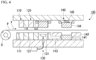
- an original steel sheet P is punched multiple times to be gradually changed into the shape of the electrical steel sheet 40 while being fed from the winding Q (the hoop) in the direction of an arrow F, the adhesive is applied to a predetermined position of the lower surface of the second and subsequent electrical steel sheets 40, and the punched electrical steel sheets 40 are sequentially stacked and press-stacked.
- the manufacturing device 100 includes a first-stage punching station 110 which is closest to the winding Q, a second-stage punching station 120 which is disposed to be close to the downstream side in the conveying direction of the original steel sheet Pin relation to the punching station 110, and an adhesive-coating station 130 which is disposed to be close to the further downstream side in relation to the punching station 120.
- the punching station 110 includes a fixed mold 111 which is disposed below the original steel sheet P and a male mold 112 which is disposed above the original steel sheet P.
- the punching station 120 includes a fixed mold 121 which is disposed below the original steel sheet P and a male mold 122 which is disposed above the original steel sheet P.
- the adhesive-coating station 130 includes an applicator 131 having a plurality of injectors disposed according to the adhesive application pattern.
- the manufacturing device 100 further includes a stacking station 140 which is disposed at a position on the downstream side of the adhesive-coating station 130.
- the stacking station 140 includes a heating device 141, a fixed mold 142 for outer shape, a heat insulation member 143, a male mold 144 for outer shape, and a spring 145.
- the heating device 141, the fixed mold 142 for outer shape, and the heat insulation member 143 are disposed below the original steel sheet P.
- the male mold 144 for outer shape and the spring 145 are disposed above the original steel sheet P.
- the original steel sheet P is first sequentially fed in the direction of an arrow F of Fig. 4 from the winding Q. Then, the original steel sheet P is first punched by the punching station 110. Next, this original steel sheet P is punched by the punching station 120.
- the original steel sheet P can have a shape of the electrical steel sheet 40 having the core back part 22 and the plurality of tooth parts 23 shown in Fig. 3 (punching step). However, since the steel sheet is not completely punched at this point, the process proceeds to the next step in the direction of an arrow F.
- the adhesive supplied from each injector of the applicator 131 is applied in a dot shape (applying step).
- the original steel sheet P is fed to the stacking station 140, is punched by the male mold 144 for outer shape, and is stacked with high accuracy (stacking step).
- the electrical steel sheet 40 receives a constant pressure from the spring 145.
- the iron core which is formed by stacking the electrical steel sheets 40 in this way is heated to, for example, 60 to 200°C by the heating device 141.
- the adhesive is cured by heating so that the adhesion part 41 is formed (curing step).
- stator core 21 is completed.
- the plurality of electrical steel sheets of which both surfaces are coated with an insulation coating are stacked and the electrical steel sheets adjacent to each other in the stacking direction are adhered to each other by the adhesion part formed by the adhesive containing the organic resin and the inorganic filler. Since the electrical steel sheets are adhered to each other by the adhesion part, it is possible to obtain sufficient adhesion strength. Since the adhesion part contains the inorganic filler, it is possible to suppress the expansion or contraction of the adhesion part.
- each adhesion part contains 5 to 50 parts by mass of the inorganic filler of which the 50% particle size is 0.2 to 3.5 ⁇ m and the 90% particle size is 10.0 ⁇ m or less with respect to 100 parts by mass of the organic resin. Therefore, the electric motor and the adhesively-laminated core according to this embodiment can easily decrease a gap between the electrical steel sheets. As a result, it is possible to further improve the flatness of the adhesively-laminated core and the space factor of the adhesively-laminated core.
- the adhesively-laminated core according to this embodiment can further improve flatness and improve space factor. Therefore, the adhesively-laminated core according to this embodiment is suitable as the adhesively-laminated core for a stator (the stator core).
- the adhesively-laminated core may be used as the rotor core.
- the shape of the stator core is not limited to the form shown in the aforementioned embodiment. Specifically, the dimensions of the outer diameter and the inner diameter of the stator core, the lamination thickness, the number of slots, the dimensional ratio between the circumferential direction and the radial direction of the tooth part 23, the dimensional ratio between the tooth part 23 and the core back part 22 in the radial direction, and the like can be arbitrarily designed according to the characteristic of the desired electric motor.
- one set of two permanent magnets 32 forms one magnetic pole, but the present invention is not limited thereto.
- one permanent magnet 32 may form one magnetic pole and three or more permanent magnets 32 may form one magnetic pole.
- the electric motor is a permanent magnetic electric motor
- the structure of the electric motor is not limited thereto as shown below.
- the structure of the electric motor may further employ various known structures not shown below.
- the electric motor may be a reluctance motor or an electromagnet field motor (a wound-field motor).
- the AC motor is a synchronous motor
- the present invention is not limited thereto.
- the electric motor may be an induction motor.
- the motor is an AC motor
- the present invention is not limited thereto.
- the electric motor may be a DC motor.
- the electric motor is a motor
- the present invention is not limited thereto.
- the electric motor may be a generator.
- the laminated core according to the present invention is applied to the stator core
- the laminated core can be also applied to the rotor core.
- a hoop with a thickness of 0.25 mm was prepared, an insulation coating treatment solution containing a metal phosphate and an acrylic resin emulsion was applied to both surfaces of the hoop, the hoop was baked at 300°C, and an insulation coating of 0.8 ⁇ m per one surface was formed.
- the hoop having the insulation coating formed thereon was wound up to form the winding Q.
- the winding Q was set on the manufacturing device 100 and the original steel sheet P was fed from the winding Q in the direction of an arrow F.
- the adhesive having a composition shown in Table 1 was applied in dots so that 5 mg of the adhesive was applied at each position shown in Fig. 3 while the punched electrical steel sheets were sequentially fed (applying step) and the electrical steel sheets were stacked (stacking step).
- applying step the electrical steel sheets were sequentially fed
- the electrical steel sheets were stacked
- stamping step the adhesively-laminated core of each example was manufactured.
- Acrylic modified epoxy resin epoxy resin: bisphenol F type, 60% by mass, acrylic resin: polymer of acrylic acid, 20% by mass, curing agent: novolac type phenolic resin, 20% by mass).
- A1 Aluminum hydroxide (50% particle size 1.5 ⁇ m, 90% particle size 6.5 ⁇ m, maximum particle size 7.0 ⁇ m).
- A2 Aluminum oxide (50% particle size 2.5 ⁇ m, 90% particle size 8.5 ⁇ m, maximum particle size 9.5 ⁇ m).
- A'1 Silicon dioxide (50% particle size 1.5 ⁇ m, 90% particle size 12.0 ⁇ m, maximum particle size 15.0 ⁇ m).
- A'2 Magnesium oxide (50% particle size 2.5 ⁇ m, 90% particle size 15.5 ⁇ m, maximum particle size 21.0 ⁇ m).
- the adhesively-laminated core obtained in each example was placed on a flat base and the height of the adhesively-laminated core was measured at eighteen positions corresponding to the tooth parts 23 of Fig. 3 .
- a difference ( ⁇ H) between the maximum value and the minimum value of the height of the adhesively-laminated core was calculated and was divided by the average value (the average height) of the height of the adhesively-laminated core to obtain the flatness ( ⁇ H/average height ⁇ 100(%)).
- the average height is the arithmetic mean value of the above 18 positions.
- the flatness of the adhesively-laminated core was evaluated based on the evaluation criteria as below. As the flatness becomes smaller, the flatness becomes excellent. The result is shown in Table 1.
- the space factor (%) of the adhesively-laminated core obtained in each example was calculated.
- Space factor % M / D ⁇ h ⁇ S ⁇ 100
- M indicates the mass (kg) of the adhesively-laminated core
- D indicates the density (kg/m 3 ) of the steel sheet (the electrical steel sheet excluding the insulation coating)
- h indicates the average height (m) of the adhesively-laminated core
- S indicates the area (m 2 ) of the electrical steel sheet in the plan view
- the area S of the electrical steel sheet was determined by capturing the electrical steel sheet before stacking as an image with a scanner and performing image analysis.
- the adhesively-laminated core of the present invention can further improve the flatness and the space factor.
- the adhesively-laminated core can further improve the flatness and improve the space factor.
- the industrial applicability is great.
Landscapes
- Engineering & Computer Science (AREA)
- Power Engineering (AREA)
- Manufacturing & Machinery (AREA)
- Chemical & Material Sciences (AREA)
- Organic Chemistry (AREA)
- Inorganic Chemistry (AREA)
- Polymers & Plastics (AREA)
- Medicinal Chemistry (AREA)
- Chemical Kinetics & Catalysis (AREA)
- Health & Medical Sciences (AREA)
- Adhesives Or Adhesive Processes (AREA)
- Iron Core Of Rotating Electric Machines (AREA)
- Laminated Bodies (AREA)
- Manufacture Of Motors, Generators (AREA)
- Manufacturing Cores, Coils, And Magnets (AREA)
Abstract
Description
- The present invention relates to an adhesively-laminated core, a manufacturing method thereof, and an electric motor.
- Priority is claimed on
Japanese Patent Application No. 2018-235871, filed December 17, 2018 - Conventionally, an adhesively-laminated core used in motors, transformers, and the like is known. The adhesively-laminated core has a configuration in which a plurality of thin electrical steel sheets are stacked and are integrated with each other by an adhesive. In the adhesively-laminated core, it is difficult to maintain flatness in accordance with an increase in the number of the stacked electrical steel sheets. In the adhesively-laminated core having poor flatness, the adhesively-laminated core may not stand upright, the adhesively-laminated core may be tilted, the accuracy of the adhesively-laminated core may not be stable, and magnetic properties of the adhesively-laminated core may deteriorate.
- In order to solve such problems, for example, Patent Document 1 proposes an adhesively-laminated core in which electrical steel sheets are adhered to each other by an adhesive containing an epoxy resin and a rubber component and the amount of the adhesive squeezed out from the outer peripheral portion of the electrical steel sheet is suppressed. The adhesively-laminated core of Patent Document 1 attempts to improve the accuracy of the film thickness of the adhesion part.
- [Patent Document 1]
Japanese Unexamined Patent Application, First Publication No. 2014-096429 - However, in the adhesively-laminated core of Patent Document 1, there is still room for further improving flatness and improving space factor.
- The present invention has been made in view of the above-described circumstances and an object of the present invention is to provide an adhesively-laminated core capable of further improving flatness and improving space factor, a manufacturing method thereof, and an electric motor.
- It is considered that the expansion or contraction of the adhesion part can be suppressed when an inorganic filler is blended with the adhesion part for adhering the electrical steel sheets to each other.
- When the expansion of the adhesion part is suppressed, it is easy to improve the space factor of the adhesively-laminated core. An increase in the space factor of the adhesively-laminated core means an increase in the ratio of the electrical steel sheet in the cross-section of the adhesively-laminated core in the stacking direction. This means that the magnetic field lines can be formed at a high density when the magnetic field lines are generated inside the adhesively-laminated core by excitation from the winding current. That is, an increase in the space factor of the adhesively-laminated core means the improvement of magnetic properties of the adhesively-laminated core.
- When the 50% particle size of the inorganic filler contained in the adhesion part is small, it is considered that the adhesively-laminated core can easily stand up, can be easily flattened, and increase the space factor.
- However, the present inventors have found that the flatness of the adhesively-laminated core is determined not only by the 50% particle size (the center particle size) of the inorganic filler or the average particle size of the inorganic filler (the arithmetic mean of the particle size of all particles of the inorganic filler) but also by the 90% particle size of the inorganic filler or the maximum particle size of the inorganic filler. That is, the present inventors have found that the flatness of the adhesively-laminated core is determined by a component having a large particle size in the population of particles of the inorganic filler.
- It is considered that the coarse particles dominate the gaps between the electrical steel sheets when the "coarse particles" are present in the population of inorganic filler particles even when the 50% particle size or the average particle size of the inorganic filler is small.
- The present inventors have carried out careful examination in order to solve the above-described problems. As a result, the present inventors have found that the flatness of the adhesively-laminated core can be further improved and the space factor of the adhesively-laminated core can be improved by decreasing the 50% particle size of the inorganic filler contained in the adhesion part and decreasing the 90% particle size of the inorganic filler contained in the adhesion part and completed the present invention.
- That is, the present invention has the following aspects.
-
- (1) A first aspect of the present invention is an adhesively-laminated core including: a plurality of electrical steel sheets which are stacked on each other and of which both surfaces are coated with an insulation coating; and an adhesion part which is provided between the electrical steel sheets adjacent to each other in a stacking direction and adheres the electrical steel sheets to each other, wherein an adhesive forming the adhesion part contains an organic resin and an inorganic filler, wherein a 50% particle size of the inorganic filler is 0.2 to 3.5 µm, wherein a 90% particle size of the inorganic filler is 10.0 µm or less, and wherein an amount of the inorganic filler is 5 to 50 parts by mass with respect to 100 parts by mass of the organic resin.
- (2) In the adhesively-laminated core according to the above (1), a maximum particle size of the inorganic filler may be 30.0 µm or less.
- (3) In the adhesively-laminated core according to the above (1) or (2), the inorganic filler may contain one or more selected from metal oxide and metal hydroxide.
- (4) In the adhesively-laminated core according to any one of the above (1) to (3), the inorganic filler may contain one or more selected from aluminum hydroxide and aluminum oxide.
- (5) The adhesively-laminated core according to any one of the above (1) to (4) may be for a stator.
- (6) A second aspect of the present invention is a method of manufacturing the adhesively-laminated core according to any one of the above (1) to (5), wherein an operation of applying the adhesive to a part of a surface of the electrical steel sheet, stacking the electrical steel sheet on another electrical steel sheet, press-stacking the electrical steel sheets, and forming the adhesion part is repeated.
- (7) A third aspect of the present invention is an electric motor including the adhesively-laminated core according to any one of the above (1) to (5).
- According to the adhesively-laminated core of the present invention, it is possible to further improve flatness and to improve space factor.
-
-
Fig. 1 is a cross-sectional view of an electric motor including an adhesively-laminated core according to an embodiment of the present invention. -
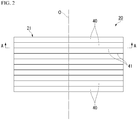
Fig. 2 is a side view of the adhesively-laminated core shown inFig. 1 . -
Fig. 3 is a cross-sectional view of A-A ofFig. 2 . -
Fig. 4 is a side view showing a schematic configuration of an adhesively-laminated core manufacturing device. - Hereinafter, an adhesively-laminated core according to an embodiment of the present invention and an electric motor including the adhesively-laminated core will be described with reference to the drawings. Additionally, in this embodiment, an electric motor as a motor, specifically, an AC motor, more specifically, a synchronous motor, and even more specifically, a permanent magnetic electric motor will be described as an example. Such a motor is suitably used in, for example, an electric vehicle or the like.
- As shown in
Fig. 1 , anelectric motor 10 includes astator 20, arotor 30, acasing 50, and arotation shaft 60. Thestator 20 and therotor 30 are accommodated in thecasing 50. - The
stator 20 is fixed to thecasing 50. - In this embodiment, the
electric motor 10 is of an inner rotor type in which therotor 30 is located on the inside of thestator 20. However, theelectric motor 10 may be of an outer rotor type in which therotor 30 is located on the outside of thestator 20. Further, in this embodiment, theelectric motor 10 is a 12-pole and 18-slot three-phase AC motor. However, the number of poles, the number of slots, the number of phases, and the like can be changed as appropriate. - The
electric motor 10 can rotate at a rotation speed of 1000 rpm, for example, by applying an excitation current having an effective value of 10 A and a frequency of 100 Hz to each phase. - The
stator 20 includes astator core 21 and a winding (not shown). - The
stator core 21 includes an annularcore back part 22 and a plurality oftooth parts 23. Hereinafter, the direction of the center axis O of the stator core 21 (or the core back part 22) is referred to as the axial direction, the radial direction (the direction orthogonal to the center axis O) of the stator core 21 (or the core back part 22) is referred to as the radial direction, and the circumferential direction (the direction to orbit around the center axis O) of the stator core 21 (or the core back part 22) is referred to as the circumferential direction. - The
core back part 22 is formed in an annular ring shape in a plan view when thestator 20 is viewed from the axial direction. - The plurality of
tooth parts 23 protrude from thecore back part 22 inward in the radial direction (toward the center axis O of thecore back part 22 in the radial direction). The plurality oftooth parts 23 are arranged at equal intervals in the circumferential direction. In this embodiment, eighteentooth parts 23 are provided at the intervals of the center angles of 20° around the center axis O. The plurality oftooth parts 23 are formed to have the same shape and the same size. - The winding is wound around the
tooth part 23. The winding may be a concentrated winding or a distributed winding. - The
rotor 30 is disposed on the inside of the radial direction with respect to the stator 20 (or the stator core 21). Therotor 30 includes arotor core 31 and a plurality ofpermanent magnets 32. - The
rotor core 31 is formed in an annular shape (annular ring shape) to be arranged coaxially with thestator 20. Therotation shaft 60 is disposed inside therotor core 31. Therotation shaft 60 is fixed to therotor core 31. - The plurality of
permanent magnets 32 are fixed to therotor core 31. In this embodiment, a set of twopermanent magnets 32 forms one magnetic pole. A plurality of sets ofpermanent magnets 32 are arranged at equal intervals in the circumferential direction. In this embodiment, twelve sets (twenty four in total) ofpermanent magnets 32 are provided at the intervals of the center angles of 30° around the center axis O. - In this embodiment, an interior permanent magnet motor is employed as the permanent magnetic electric motor.
- A plurality of through
holes 33 penetrating therotor core 31 in the axial direction are formed in therotor core 31. The plurality of throughholes 33 are provided to correspond to the plurality ofpermanent magnets 32. Eachpermanent magnet 32 is fixed to therotor core 31 while being disposed inside the corresponding throughhole 33. Eachpermanent magnet 32 can be fixed to therotor core 31, for example, in such a manner that the outer surface of thepermanent magnet 32 and the inner surface of the throughhole 33 are adhered to each other by an adhesive. Additionally, as the permanent magnetic electric motor, a surface permanent magnet motor may be used instead of the interior permanent magnet motor. - Both the
stator core 21 and therotor core 31 are adhesively-laminated cores.
As shown inFig. 2 , thestator 20 is formed by stacking a plurality ofelectrical steel sheets 40. - In the
stator 20, anadhesion part 41 for adhering theseelectrical steel sheets 40 is provided between theelectrical steel sheets 40 which are adjacent to each other in the stacking direction and theelectrical steel sheets 40 are adhered to each other by theadhesion part 41. That is, in thestator 20, the plurality ofelectrical steel sheets 40 forming thestator core 21 are stacked with theadhesion part 41 interposed therebetween. - The lamination thickness of each of the
stator core 21 and therotor core 31 is, for example, 50.0 mm. The outer diameter of thestator core 21 is, for example, 250.0 mm. The inner diameter of thestator core 21 is, for example, 165.0 mm. The outer diameter of therotor core 31 is, for example, 163.0 mm. The inner diameter of therotor core 31 is, for example, 30.0 mm. However, these values are examples, and the lamination thickness, outer diameter, or inner diameter of thestator core 21 and the lamination thickness, outer diameter, or inner diameter of therotor core 31 are not limited to these values. Here, the inner diameter of thestator core 21 is based on the tip of thetooth part 23 of thestator core 21. The inner diameter of thestator core 21 is the diameter of the virtual circle inscribed in the tips of alltooth parts 23. - Each of the
electrical steel sheets 40 forming thestator core 21 and therotor core 31 is formed, for example, by punching an electrical steel sheet as a base material. A known electrical steel sheet can be used for theelectrical steel sheet 40. The chemical composition of theelectrical steel sheet 40 is not particularly limited. In this embodiment, a non-grain-oriented electrical steel sheet is employed as theelectrical steel sheet 40. As the non-grain-oriented electrical steel sheet, for example, a non-grain-oriented electrical steel strip of JIS C 2552: 2014 can be employed. - However, as the
electrical steel sheet 40, a grain-oriented electrical steel sheet can be employed instead of the non-grain-oriented electrical steel sheet. As the grain-oriented electrical steel sheet, a grain-oriented electrical steel strip of JIS C 2553: 2012 can be employed. - In order to improve the workability of the electrical steel sheet or the iron loss of the laminated core, an insulation coating is provided on both surfaces of the
electrical steel sheet 40. As a material constituting the insulation coating, for example, (1) an inorganic compound, (2) an organic resin, (3) a mixture of an inorganic compound and an organic resin, and the like can be applied. Examples of the inorganic compound include (1) a complex of dichromate and boric acid, (2) a complex of phosphate and silica, (3) phosphate, and the like. Examples of the organic resin include an epoxy resin, an acrylic resin, an acrylic styrene resin, a polyester resin, a silicone resin, a fluororesin, and the like. - The organic resin may be the same as or different from the organic resin contained in the adhesive described later.
- In order to ensure the insulating performance between the
electrical steel sheets 40 stacked with each other, the thickness of the insulation coating (thickness per one side of the electrical steel sheet 40) is preferably 0.1 µm or more. - On the other hand, the insulation effect becomes saturated as the insulation coating becomes thick. Further, as the insulation coating becomes thick, a space factor decreases and the performance as the adhesively-laminated core decreases. Thus, the insulating coating should be as thin as possible in the range capable of ensuring the insulation performance. The thickness of the insulation coating (the thickness per one side of the electrical steel sheet 40) is preferably 0.1 µm or more and 5 µm or less. The thickness of the insulation coating is more preferably 0.1 µm or more and 2 µm or less.
- The thickness of the insulation coating can be measured, for example, by observing the cut surface of the
electrical steel sheet 40 cut in the thickness direction with a microscope or the like. - As the
electrical steel sheet 40 becomes thin, the iron loss improvement effect gradually becomes saturated. Further, the manufacturing cost of theelectrical steel sheet 40 increases as theelectrical steel sheet 40 becomes thin. Therefore, the thickness of theelectrical steel sheet 40 is preferably 0.10 mm or more in consideration of the iron loss improvement effect and the manufacturing cost. - On the other hand, when the
electrical steel sheet 40 is too thick, the press punching work of theelectrical steel sheet 40 becomes difficult. Therefore, the thickness of theelectrical steel sheet 40 is preferably 0.65 mm or less in consideration of the press punching work of theelectrical steel sheet 40. - Further, the iron loss increases as the
electrical steel sheet 40 becomes thick. Therefore, the thickness of theelectrical steel sheet 40 is preferably 0.35 mm or less, more preferably 0.25 mm or less, and even more preferably 0.20 mm or less in consideration of the iron loss characteristics of theelectrical steel sheet 40. - In consideration of the above points, the thickness of each
electrical steel sheet 40 is, for example, preferably 0.10 mm or more and 0.65 mm or less, more preferably 0.10 mm or more and 0.35 mm or less, even more preferably 0.10 mm or more and 0.25 mm or less, and particularly preferably 0.10 mm or more and 0.20 mm or less. Further, the thickness of theelectrical steel sheet 40 also includes the thickness of the insulation coating. - The thickness of the
electrical steel sheet 40 can be measured by, for example, a micrometer or the like. - As shown in
Fig. 3 , the plurality ofelectrical steel sheets 40 forming thestator core 21 are stacked with theadhesion part 41 interposed therebetween. Theadhesion part 41 is formed in the core backpart 22 and thetooth part 23 of thestator core 21. Theadhesion part 41 is formed from the inner periphery of the core backpart 22 inward in the radial direction (toward the center axis O of the core backpart 22 in the radial direction) asadhesion parts tooth parts 23 are respectively provided with theadhesion parts adhesion part 41a is formed in each of the core backpart 22 at a position corresponding to the plurality oftooth parts 23. - The
adhesion part 41 is a layer which is formed by an adhesive containing an organic resin and an inorganic filler. - The organic resin constituting the adhesive is not particularly limited and examples thereof include a polyolefin resin, an acrylic resin, a polyurethane resin, an epoxy resin, a polyamide resin, a polyimide resin, a polyester resin, a silicone resin, and a fluororesin.
- As the organic resin, an acrylic modified epoxy resin obtained by graft-polymerizing an acrylic resin on an epoxy resin is preferable from the viewpoint of easily increasing the adhesion strength of the
adhesion part 41. - Examples of the epoxy resin include those obtained by condensing epichlorohydrin and bisphenol in the presence of an alkaline catalyst, those obtained by condensing epichlorohydrin and bisphenol into a low molecular weight epoxy resin in the presence of an alkaline catalyst and subjecting the low molecular weight epoxy resin and bisphenol to a polyaddition reaction, and the like. Here, the "low molecular weight epoxy resin" means an epoxy resin having a number average molecular weight smaller than 1200.
- The epoxy resin may be an epoxy ester resin in which a divalent carboxylic acid is combined. Examples of the divalent carboxylic acid include succinic acid, adipic acid, pimelic acid, azelaic acid, sebacic acid, dodecanedioic acid, hexahydrophthalic acid and the like.
- Examples of bisphenol include bisphenol A, bisphenol F, bisphenol AD, and the like, and bisphenol A and bisphenol F are preferable.
- Examples of the alkaline catalyst include sodium hydroxide, potassium hydroxide, and the like.
- One type of these epoxy resins may be used alone or two or more types may be used in combination.
- The number average molecular weight of the epoxy resin is preferably 1200 to 8000, more preferably 2000 to 7000, and even more preferably 2500 to 7000. When the number average molecular weight of the epoxy resin is equal to or larger than the lower limit value, it is easy to increase the adhesion strength of the
adhesion part 41. When the number average molecular weight of the epoxy resin is equal to or smaller than the upper limit value, it is easy to increase the stability of theadhesion part 41. - The number average molecular weight of the epoxy resin can be measured by size-exclusion chromatography (SEC) described in JIS K 7252-1: 2008 using polystyrene as a standard substance.
- The amount of the epoxy resin is, for example, preferably 30 to 90% by mass, more preferably 40 to 80% by mass, and even more preferably 50 to 70% by mass with respect to the total mass of the adhesive. When the amount of the epoxy resin is equal to or larger than the lower limit value, it is easy to increase the adhesion strength of the
adhesion part 41. When the amount of the epoxy resin is equal to or smaller than the upper limit value, it is easy to alleviate the strain generated in theelectrical steel sheet 40. - Examples of the acrylic resin include an acrylic resin obtained by polymerizing or copolymerizing at least one selected from unsaturated carboxylic acids such as acrylic acid, methacrylic acid, maleic acid, itaconic acid, and crotonic acid, an acrylic resin obtained by copolymerizing at least one monomer selected from the unsaturated carboxylic acids and at least one selected from the following radically polymerizable unsaturated monomers, and the like.
- Examples of the radically polymerizable unsaturated monomers include (1) hydroxyalkyl esters of acrylic acid or methacrylic acid with 1 to 8 carbon atoms, such as 2-hydroxyethyl acrylate, 2-hydroxyethyl methacrylate, hydroxypropyl acrylate, and hydroxypropyl methacrylate, (2) alkyl esters or cycloalkyl esters of acrylic acid or methacrylic acid with 1 to 24 carbon atoms, such as methyl acrylate, methyl methacrylate, ethyl acrylate, ethyl methacrylate, n-butyl acrylate, n-butyl methacrylate, isobutyl acrylate, isobutyl methacrylate, tert-butyl acrylate, tert-butyl methacrylate, cyclohexyl acrylate, cyclohexyl methacrylate, 2-ethylhexyl acrylate, 2-ethylhexyl methacrylate, lauryl acrylate, lauryl methacrylate, stearyl acrylate, stearyl methacrylate, and decyl acrylate, (3) functional acrylamides or functional methacrylamides, such as acrylamide, methacrylamide, N-methylacrylamide, N-ethylacrylamide, diacetoneacrylamide, N-methylolacrylamide, N-methylolmethacrylamide, N-methoxymethylacrylamide, and N-butoxymethylacrylamide, (4) aromatic vinyl monomers such as styrene, vinyltoluene, and α-methylstyrene, (5) aliphatic vinyl monomers such as vinyl acetate, vinyl propionate, acrylonitrile, and methacrylonitrile, and the like.
- Preferred combinations of the above unsaturated monomers include, for example, a combination of methyl methacrylate, 2-ethylhexyl acrylate, and acrylic acid, a combination of styrene, methyl methacrylate, ethyl acrylate, and methacrylic acid, a combination of styrene, ethyl acrylate, and methacrylic acid, a combination of methyl methacrylate, ethyl acrylate, and acrylic acid, and the like.
- The number average molecular weight of the acrylic resin is preferably 5,000 to 100,000, more preferably 6,000 to 80,000, and even more preferably 7,000 to 60,000. When the number average molecular weight of the acrylic resin is equal to or larger than the lower limit value, it is easy to increase the adhesion strength of the
adhesion part 41. When the number average molecular weight of the acrylic resin is equal to or smaller than the upper limit value, it is easy to suppress the high viscosity of the adhesive and to flatten theadhesion part 41. - The number average molecular weight of the acrylic resin can be measured by the same method as the number average molecular weight of the epoxy resin.
- The amount of the acrylic resin is, for example, preferably 10 to 40% by mass, more preferably 15 to 35% by mass, and even more preferably 20 to 30% by mass with respect to the total mass of the adhesive. When the amount of the acrylic resin is equal to or larger than the lower limit value, it is easy to increase the adhesion strength of the
adhesion part 41. When the amount of the acrylic resin is equal to or smaller than the upper limit value, it is easy to suppress the high viscosity of the adhesive and to flatten theadhesion part 41. Therefore, it is easy to suppress the strain of the adhesively-laminated core. - An acrylic modified epoxy resin (hereinafter, also referred to as "grafted product") obtained, for example, by graft-polymerizing an acrylic resin on an epoxy resin can be obtained by subjecting the above-described radically polymerizable unsaturated monomer to a graft polymerization reaction on a high molecular weight epoxy resin in the presence of a radical generator such as benzoyl peroxide in an organic solvent solution. Here, the "high molecular weight epoxy resin" means an epoxy resin having a number average molecular weight of 1200 or more.
- The radical generator used in the graft polymerization reaction is preferably 3 to 15 parts by mass with respect to 100 parts by mass of the solid content of the radically polymerizable unsaturated monomer.
- The graft polymerization reaction can be performed, for example, by adding a radically polymerizable unsaturated monomer, which is uniformly mixed with a radical generator, to an organic solvent solution of a high molecular weight epoxy resin heated at 80 to 150°C over 1 to 3 hours and maintaining the temperature over 1 to 3 hours.
- The organic solvent used in the graft polymerization reaction may be any organic solvent that dissolves the high molecular weight epoxy resin and the radically polymerizable unsaturated monomer and can be mixed with water.
- Examples of such an organic solvent include alcohol solvent such as isopropanol, butyl alcohol, 2-hydroxy-4-methylpentane, 2-ethylhexyl alcohol, cyclohexanol, ethylene glycol, diethylene glycol, 1,3-butylene glycol, ethylene glycol monoethyl ether, ethylene glycol monobutyl ether, and diethylene glycol monomethyl ether, ketone solvent such as acetone and methyl ethyl ketone, cellosolve solvent, and carbitol solvent. Further, an inert organic solvent that is immiscible with water can also be used and examples of such an organic solvent include aromatic hydrocarbons such as toluene and xylene, and esters such as ethyl acetate and butyl acetate.
- When the adhesive contains an epoxy resin, the curing agent can be a commonly used epoxy resin curing agent. As the epoxy resin curing agent, for example, at least one selected from polyamine-based curing agents such as aliphatic polyamines, alicyclic polyamines, aromatic polyamines, polyamide polyamines, and modified polyamines; acid anhydride-based curing agents such as monofunctional acid anhydride (phthalic anhydride, hexahydrophthalic anhydride, methyltetrahydrophthalic anhydride, methylhexahydrophthalic anhydride, methylnadic anhydride, chlorendic anhydride, and the like), bifunctional acid anhydrides (pyromellitic anhydride, benzophenone tetracarboxylic acid anhydride, ethylene glycol bis(anhydrotrimate), methylcyclohexenetetracarboxylic acid anhydride, and the like), and free acid anhydride (trimellitic anhydride, polyazelaic anhydride, and the like); initial condensate containing methylol groups such as a novolac type or resol type phenol resin, a urea resin, and a melamine resin; and latent curing agents can be used.
- Examples of the latent curing agent include dicyandiamide, melamine, organic acid dihydrazide, amineimide, ketimine, tertiary amine, imidazole salt, boron trifluoride amine salt, a microcapsule type curing agent (a substance in which a curing agent is encapsulated in microcapsules formed of casein or the like and the microcapsules are broken by heating and pressurizing to perform a curing reaction with a resin), a molecular sieve type curing agent (a substance in which a curing agent is adsorbed on the surface of an adsorptive compound, which releases adsorbed molecules by heating and undergoes a curing reaction with a resin), and the like.
- As the epoxy resin curing agent, a novolac type phenol resin (phenol novolac resin) is preferable from the viewpoint of easily increasing the adhesion strength of the
adhesion part 41. Here, the "novolac type phenol resin" means a resin obtained by subjecting phenols and aldehydes to a condensation reaction using an acid catalyst. - Examples of phenols include phenol.
- Examples of aldehydes include formaldehyde.
- Examples of the acid catalyst include oxalic acid and divalent metal salts.
- The novolac type phenol resin is solid at a room temperature (25°C) and is classified as a thermoplastic resin. In the novolac type phenol resin, -CH2OH groups are hardly bonded to the phenol nuclei (aromatic rings) constituting the phenol resin.
- The amount of the epoxy resin curing agent is preferably 1 to 20% by mass, for example, with respect to the total mass of the adhesive. When the amount of the epoxy resin curing agent is equal to or larger than the lower limit value, it is easy to increase the adhesion strength of the
adhesion part 41. When the amount of the epoxy resin curing agent is equal to or smaller than the upper limit value, it is easy to increase the stability of theadhesion part 41. - The adhesive may contain an elastomer. Examples of the elastomer include natural rubber and synthetic rubber and synthetic rubber is preferable.
- Examples of the synthetic rubber include polybutadiene-based synthetic rubber, nitrile-based synthetic rubber, and chloroprene-based synthetic rubber.
- Examples of the polybutadiene synthetic rubber include isoprene rubber (IR), butadiene rubber (BR), styrene butadiene rubber (SBR), polyisobutylene (butyl rubber, IIR), and ethylene propylene diene rubber (EPDM).
- Examples of the nitrile-based synthetic rubber include acrylonitrile butadiene rubber (NBR) and acrylic rubber (ACM).
- Examples of the chloroprene-based synthetic rubber include chloroprene rubber (CR).
- As the synthetic rubber, urethane rubber, silicone rubber, fluororubber (FKM), chlorosulfonated polyethylene (CSM), epichlorohydrin rubber (ECO), and the like may be used in addition to the above examples.
- As the elastomer, SBR, EPDM, and NBR are preferable from the viewpoints of excellent heat resistance and easy relaxation of strain generated in the
electrical steel sheet 40. - One type of elastomer may be used alone or two or more types may be used in combination.
- The amount of the elastomer is preferably 5 to 30% by mass with respect to the total mass of the adhesive. When the amount of the elastomer is equal to or larger than the lower limit value, it is easy to alleviate the strain generated in the
electrical steel sheet 40. - When the amount of the elastomer is equal to or smaller than the upper limit value, it is easy to increase the adhesion strength of the
adhesion part 41. - The amount of the organic resin is, for example, preferably 40 to 95% by mass, more preferably 50 to 90% by mass, and even more preferably 60 to 80% by mass with respect to the total mass of the adhesive. When the amount of the organic resin is equal to or larger than the lower limit value, it is easy to increase the adhesion strength of the
adhesion part 41. When the amount of the organic resin is equal to or smaller than the upper limit value, it is easy to suppress the high viscosity of the adhesive and to flatten theadhesion part 41. Therefore, it is easy to suppress the strain of the adhesively-laminated core. - Examples of the inorganic filler include metal oxides such as aluminum oxide (a-alumina), zinc oxide, titanium oxide, calcium oxide, magnesium oxide, iron oxide, and tin oxide; metal hydroxides such as aluminum hydroxide (gibbsite), calcium hydroxide, and magnesium hydroxide; silicon-containing substances such as silica, diatomaceous earth, calcium silicate, and talc; sulfates such as calcium sulfate, magnesium sulfate, and barium sulfate, and the like.
- One type of inorganic filler may be used alone or two or more types may be used in combination.
- As the inorganic filler, one or more selected from metal oxides and metal hydroxides is preferable, one or more selected from aluminum hydroxide and aluminum oxide is more preferable, and aluminum hydroxide is even more preferable from the viewpoint of low cost and easy availability.
- The 50% particle size of the inorganic filler is 0.2 to 3.5 µm, preferably 0.4 to 3.0 µm, and more preferably 0.6 to 2.5 µm. When the 50% particle size of the inorganic filler is equal to or larger than the lower limit value, it is easy to suppress the expansion or contraction of the
adhesion part 41. When the 50% particle size of the inorganic filler is equal to or smaller than the upper limit value, it is easy to increase the space factor of the adhesively-laminated core. - When the inorganic filler is a metal oxide, the 50% particle size of the inorganic filler is preferably 1.0 to 3.5 µm, more preferably 1.5 to 3.2 µm, and even more preferably 2.0 to 3.0 µm.
- When the inorganic filler is a metal hydroxide, the 50% particle size of the inorganic filler is preferably 0.2 to 3.0 µm, more preferably 0.5 to 2.5 µm, and even more preferably 1.0 to 2.0 µm.
- The 90% particle size of the inorganic filler is 10.0 µm or less, preferably 8.0 µm or less, and even more preferably 6.0 µm or less. When the 90% particle size of the inorganic filler is equal to or smaller than the upper limit value, it is easy to flatten the
adhesion part 41. Therefore, it is easy to suppress the strain of the adhesively-laminated core. The lower limit value of the 90% particle size of the inorganic filler is not particularly limited, but is substantially 2.0 µm. - When the inorganic filler is a metal oxide, the 90% particle size of the inorganic filler is preferably 10.0 µm or less, more preferably 9.5 µm or less, and even more preferably 9.0 µm or less.
- When the inorganic filler is a metal hydroxide, the 90% particle size of the inorganic filler is preferably 9.0 µm or less, more preferably 8.0 µm or less, and even more preferably 7.0 µm or less.
- In the present specification, the 50% particle size and the 90% particle size represent the volume-based particle size in the cumulative particle size distribution.
The 50% particle size and the 90% particle size can be measured by using a laser diffraction/scattering particle size distribution measuring device. The 50% particle size represents the particle size when the integrated amount occupies 50% on a volume basis in the cumulative particle size curve of the particle size distribution measured using a laser diffraction/scattering particle size distribution measuring device. The 90% particle size represents the particle size when the integrated amount occupies 90% on a volume basis in the cumulative particle size curve of the particle size distribution measured using a laser diffraction/scattering particle size distribution measuring device. - The 90% particle size of the inorganic filler can be adjusted by a method of allowing the inorganic filler to pass through a sieve having a specific opening, a wind power classification method, or the like.
- The maximum particle size of the inorganic filler is preferably 30.0 µm or less, more preferably 20.0 µm or less, and even more preferably 10.0 µm or less. When the maximum particle size of the inorganic filler is equal to or smaller than the upper limit value, it is easy to flatten the
adhesion part 41. Therefore, it is easy to suppress the strain of the adhesively-laminated core. - The lower limit value of the maximum particle size of the inorganic filler is not particularly limited, but is substantially 3.0 µm.
- When the inorganic filler is a metal oxide, the maximum particle size of the inorganic filler is preferably 20.0 µm or less, more preferably 15.0 µm or less, and even more preferably 10.0 µm or less.
- When the inorganic filler is a metal hydroxide, the maximum particle size of the inorganic filler is preferably 15.0 µm or less, more preferably 10.0 µm or less, and even more preferably 8.0 µm or less.
- The maximum particle size of the inorganic filler can be measured using a laser diffraction/scattering particle size distribution measuring device. The maximum particle size of the inorganic filler is given by the maximum value of all particles measured using a laser diffraction/scattering particle size distribution measuring device.
- The maximum particle size of the inorganic filler can be adjusted by a method of allowing the inorganic filler to pass through a sieve having a specific opening, a wind power classification method, or the like.
- The amount of the inorganic filler is 5 to 50 parts by mass, preferably 5 to 40 parts by mass, more preferably 5 to 30 parts by mass, and even more preferably 10 to 30 parts by mass with respect to 100 parts by mass of the organic resin. When the amount of the inorganic filler is equal to or larger than the lower limit value, it is easy to suppress the expansion or contraction of the
adhesion part 41. When the amount of the inorganic filler is equal to or smaller than the upper limit value, it is easy to increase the space factor of the adhesively-laminated core. - When the inorganic filler is a metal oxide, the amount of the inorganic filler is preferably 10 to 50 parts by mass, more preferably 15 to 40 parts by mass, and even more preferably 20 to 30 parts by mass with respect to 100 parts by mass of the organic resin.
- When the inorganic filler is a metal hydroxide, the amount of the inorganic filler is preferably 5 to 45 parts by mass, more preferably 10 to 40 parts by mass, and even more preferably 15 to 35 parts by mass with respect to 100 parts by mass of the organic resin.
- The adhesive of this embodiment may contain an arbitrary component in addition to the organic resin and the inorganic filler. Examples of the arbitrary component include conductive substances, rust preventive additives such as sparingly soluble chromate, coloring pigments (for example, condensed polycyclic organic pigments, phthalocyanine organic pigments, and the like), coloring dyes (for example, azo dyes, azo metal complex salt dyes, and the like), deposition aid, dispersibility improver, defoaming agent, and the like.
- These arbitrary components may be used alone or in combination of two or more.
- When the adhesive contains an arbitrary component, the amount of the arbitrary component is preferably 1 to 10 parts by mass with respect to 100 parts by mass of the organic resin.
- As the adhesive of this embodiment, a radical polymerization type adhesive or the like other than thermosetting adhesive can be also used. From the viewpoint of productivity, a room temperature curing type adhesive is preferable. The room temperature curing type adhesive is cured at 20°C to 30°C. As the room temperature curing type adhesive, an acrylic-based adhesive is preferable. As the representative acrylic-based adhesive, a second generation acrylic-based adhesive (SGA) or the like is known. All of an anaerobic adhesive, an instant adhesive, and an elastomer-containing acrylic-based adhesive can be used as long as the effects of the present invention are not impaired. Additionally, the adhesive mentioned herein refers to the state before curing. When the adhesive is cured, the
adhesion part 41 is obtained. - An average tensile modulus of elasticity E at a room temperature (20°C to 30°C) of the
adhesion part 41 is set in the range of 1500 MPa to 4500 MPa. When the average tensile modulus of elasticity E of theadhesion part 41 is smaller than 1500 MPa, a problem arises in that the rigidity of the laminated core decreases. Therefore, the lower limit value of the average tensile modulus of elasticity E of theadhesion part 41 is set to 1500 MPa and more preferably 1800 MPa. In contrast, when the average tensile modulus of elasticity E of theadhesion part 41 exceeds 4500 MPa, a problem arises in that the insulation coating formed on the surface of theelectrical steel sheet 40 is peeled off. Therefore, the upper limit value of the average tensile modulus of elasticity E of theadhesion part 41 is set to 4500 MPa and more preferably 3650 MPa. - Additionally, the average tensile modulus of elasticity E is measured by a resonance method. Specifically, the tensile modulus of elasticity is measured based on JIS R 1602: 1995.
- More specifically, a measurement sample (not shown) is prepared first. This sample can be obtained by adhering two
electrical steel sheets 40 by an adhesive which is a measurement object and curing the adhesive to form theadhesion part 41. When the adhesive is of a thermosetting type, this curing is performed by heating and pressurizing under the heating and pressurizing conditions in actual operation. On the other hand, when the adhesive is of a room temperature curing type, this curing is performed by pressurizing under a room temperature. - Then, the tensile modulus of elasticity for this sample is measured by a resonance method. A method of measuring the tensile modulus of elasticity according to the resonance method is performed based on JIS R 1602: 1995 as described above. Then, the tensile modulus of elasticity of the
adhesion part 41 alone can be obtained by removing the influence of theelectrical steel sheet 40 itself from the tensile modulus of elasticity (measured value) of the sample by calculation. - Since the tensile modulus of elasticity obtained from the sample in this way becomes equal to the average value of the whole laminated core, this value is regarded as the average tensile modulus of elasticity E. The composition of the average tensile modulus of elasticity E is set so that the stacking position in the stacking direction or the circumferential position around the center axis of the laminated core is almost unchanged. Therefore, the average tensile modulus of elasticity E can be set to a value obtained by measuring at the cured
adhesion part 41 at the upper end position of the stator core. - As an adhering method, for example, a method of applying the adhesive to the
electrical steel sheet 40 and adhering the electrical steel sheets by one or both of the heating and press-stacking can be employed. Further, the heating means may be any means such as heating in a high temperature bath or an electric furnace or a method of directly energizing. - In order to obtain stable and sufficient adhesion strength, the thickness of the
adhesion part 41 is preferably 1 µm or more. - On the other hand, when the thickness of the
adhesion part 41 exceeds 100 µm, an adhesion force becomes saturated. Further, as theadhesion part 41 becomes thick, a surface factor decreases and magnetic properties such as iron loss of the adhesively-laminated core decrease. Thus, the thickness of theadhesion part 41 is preferably 1 µm or more and 100 µm or less and more preferably 1 µm or more and 10 µm or less. - In the description above, the thickness of the
adhesion part 41 means the average thickness of theadhesion part 41. - The average thickness of the
adhesion part 41 is preferably 1.0 µm or more and 3.0 µm or less. When the average thickness of theadhesion part 41 is smaller than 1.0 µm, a sufficient adhesion force can be secured as described above. Therefore, the lower limit value of the average thickness of theadhesion part 41 is 1.0 µm and more preferably 1.2 µm. In contrast, when the average thickness of theadhesion part 41 becomes thicker than 3.0 µm, a problem arises in that the strain amount of theelectrical steel sheet 40 largely increases due to cure shrinkage during thermosetting. Therefore, the upper limit value of the average thickness of theadhesion part 41 is 3.0 µm and more preferably 2.6 µm. - The average thickness of the
adhesion part 41 is an average value of the adhesively-laminated core as a whole. The average thickness of theadhesion part 41 is almost unchanged depending on the stacking position in the stacking direction or the circumferential position around the center axis of the adhesively-laminated core. Therefore, the average thickness of theadhesion part 41 can be set to the average value of the numerical values measured at ten or more positions in the circumferential direction at the upper end position of the adhesively-laminated core. - Additionally, the average thickness of the
adhesion part 41 can be adjusted by changing, for example, the adhesive application amount. Further, the average tensile modulus of elasticity E of theadhesion part 41 can be adjusted by changing one or both of the heating and pressurizing conditions applied at the time of adhesion and the types of the curing agent, for example, in the case of the thermosetting adhesive. - In this embodiment, the plurality of
electrical steel sheets 40 constituting therotor core 31 are fixed to each other by fastening C (dowel). However, the plurality ofelectrical steel sheets 40 forming therotor core 31 may be adhered to each other by theadhesion part 41. - Additionally, the adhesively-laminated core such as the
stator core 21 or therotor core 31 may be formed by so-called turn-stacking. - Hereinafter, an adhesively-laminated core manufacturing method according to an embodiment of the present invention will be described with reference to the drawings.
- The
stator core 21 can be manufactured by repeating the operation of applying the adhesive to a part of the surface of theelectrical steel sheet 40, stacking the electrical steel sheet on another electrical steel sheet, press-stacking the electrical steel sheets, and forming theadhesion part 41. - Hereinafter, a method of manufacturing the
stator core 21 using themanufacturing device 100 shown inFig. 4 will be described. - First, the
manufacturing device 100 will be described. In themanufacturing device 100, an original steel sheet P is punched multiple times to be gradually changed into the shape of theelectrical steel sheet 40 while being fed from the winding Q (the hoop) in the direction of an arrow F, the adhesive is applied to a predetermined position of the lower surface of the second and subsequentelectrical steel sheets 40, and the punchedelectrical steel sheets 40 are sequentially stacked and press-stacked. - As shown in
Fig. 4 , themanufacturing device 100 includes a first-stage punching station 110 which is closest to the winding Q, a second-stage punching station 120 which is disposed to be close to the downstream side in the conveying direction of the original steel sheet Pin relation to the punchingstation 110, and an adhesive-coating station 130 which is disposed to be close to the further downstream side in relation to the punchingstation 120. - The punching
station 110 includes a fixedmold 111 which is disposed below the original steel sheet P and amale mold 112 which is disposed above the original steel sheet P. - The punching
station 120 includes a fixedmold 121 which is disposed below the original steel sheet P and amale mold 122 which is disposed above the original steel sheet P. - The adhesive-
coating station 130 includes anapplicator 131 having a plurality of injectors disposed according to the adhesive application pattern. - The
manufacturing device 100 further includes a stackingstation 140 which is disposed at a position on the downstream side of the adhesive-coating station 130. The stackingstation 140 includes aheating device 141, a fixedmold 142 for outer shape, aheat insulation member 143, amale mold 144 for outer shape, and aspring 145. - The
heating device 141, the fixedmold 142 for outer shape, and theheat insulation member 143 are disposed below the original steel sheet P. On the other hand, themale mold 144 for outer shape and thespring 145 are disposed above the original steel sheet P. - In the
manufacturing device 100, the original steel sheet P is first sequentially fed in the direction of an arrow F ofFig. 4 from the winding Q. Then, the original steel sheet P is first punched by the punchingstation 110. Next, this original steel sheet P is punched by the punchingstation 120. By these punching processes, the original steel sheet P can have a shape of theelectrical steel sheet 40 having the core backpart 22 and the plurality oftooth parts 23 shown inFig. 3 (punching step). However, since the steel sheet is not completely punched at this point, the process proceeds to the next step in the direction of an arrow F. In the adhesive-coating station 130 of the next step, the adhesive supplied from each injector of theapplicator 131 is applied in a dot shape (applying step). - Next, the original steel sheet P is fed to the stacking
station 140, is punched by themale mold 144 for outer shape, and is stacked with high accuracy (stacking step). At the time of stacking, theelectrical steel sheet 40 receives a constant pressure from thespring 145. When the punching step, the applying step, and the stacking step described above are repeated sequentially, a predetermined number ofelectrical steel sheets 40 can be stacked. The iron core which is formed by stacking theelectrical steel sheets 40 in this way is heated to, for example, 60 to 200°C by theheating device 141. The adhesive is cured by heating so that theadhesion part 41 is formed (curing step). - With the aforementioned steps, the
stator core 21 is completed. - As described above, in the electric motor and the adhesively-laminated core according to this embodiment, the plurality of electrical steel sheets of which both surfaces are coated with an insulation coating are stacked and the electrical steel sheets adjacent to each other in the stacking direction are adhered to each other by the adhesion part formed by the adhesive containing the organic resin and the inorganic filler. Since the electrical steel sheets are adhered to each other by the adhesion part, it is possible to obtain sufficient adhesion strength. Since the adhesion part contains the inorganic filler, it is possible to suppress the expansion or contraction of the adhesion part.
- In addition, each adhesion part contains 5 to 50 parts by mass of the inorganic filler of which the 50% particle size is 0.2 to 3.5 µm and the 90% particle size is 10.0 µm or less with respect to 100 parts by mass of the organic resin. Therefore, the electric motor and the adhesively-laminated core according to this embodiment can easily decrease a gap between the electrical steel sheets. As a result, it is possible to further improve the flatness of the adhesively-laminated core and the space factor of the adhesively-laminated core.
- The adhesively-laminated core according to this embodiment can further improve flatness and improve space factor. Therefore, the adhesively-laminated core according to this embodiment is suitable as the adhesively-laminated core for a stator (the stator core). The adhesively-laminated core may be used as the rotor core.
- The technical scope of the present invention is not limited to the aforementioned embodiment and various modifications can be made without departing from the gist of the present invention.
- The shape of the stator core is not limited to the form shown in the aforementioned embodiment. Specifically, the dimensions of the outer diameter and the inner diameter of the stator core, the lamination thickness, the number of slots, the dimensional ratio between the circumferential direction and the radial direction of the
tooth part 23, the dimensional ratio between thetooth part 23 and the core backpart 22 in the radial direction, and the like can be arbitrarily designed according to the characteristic of the desired electric motor. - In the rotor of the aforementioned embodiment, one set of two
permanent magnets 32 forms one magnetic pole, but the present invention is not limited thereto. For example, onepermanent magnet 32 may form one magnetic pole and three or morepermanent magnets 32 may form one magnetic pole. - In the aforementioned embodiment, an example in which the electric motor is a permanent magnetic electric motor has been described, but the structure of the electric motor is not limited thereto as shown below. The structure of the electric motor may further employ various known structures not shown below.
- In the aforementioned embodiment, an example in which the synchronous motor is a permanent magnetic electric motor has been described, but the present invention is not limited thereto. For example, the electric motor may be a reluctance motor or an electromagnet field motor (a wound-field motor).
- In the aforementioned embodiment, an example in which the AC motor is a synchronous motor has been described, but the present invention is not limited thereto. For example, the electric motor may be an induction motor.
- In the aforementioned embodiment, an example in which the motor is an AC motor has been described, but the present invention is not limited thereto. For example, the electric motor may be a DC motor.
- In the aforementioned embodiment, an example in which the electric motor is a motor has been described, but the present invention is not limited thereto. For example, the electric motor may be a generator.
- In the aforementioned embodiment, a case in which the laminated core according to the present invention is applied to the stator core has been exemplified, but the laminated core can be also applied to the rotor core.
- In addition, it is possible to replace the components in the above embodiment with well-known components as appropriate without departing from the gist of the present invention. Further, the aforementioned modified examples may be appropriately combined with each other.
- A hoop with a thickness of 0.25 mm was prepared, an insulation coating treatment solution containing a metal phosphate and an acrylic resin emulsion was applied to both surfaces of the hoop, the hoop was baked at 300°C, and an insulation coating of 0.8 µm per one surface was formed.
- The hoop having the insulation coating formed thereon was wound up to form the winding Q. The winding Q was set on the
manufacturing device 100 and the original steel sheet P was fed from the winding Q in the direction of an arrow F. A single plate (electrical steel sheet 40) having an annular shape with an outer diameter of 300 mm and an inner diameter of 240 mm and having eighteen rectangular tooth parts with a length of 30 mm and a width of 15 mm formed on the inner radial side was formed by punching using the manufacturing device 100 (punching step). - Next, the adhesive having a composition shown in Table 1 was applied in dots so that 5 mg of the adhesive was applied at each position shown in
Fig. 3 while the punched electrical steel sheets were sequentially fed (applying step) and the electrical steel sheets were stacked (stacking step). By repeating the same operation, a laminated body in which 130 electrical steel sheets were stacked was obtained. The obtained laminated body was heated at 120°C while being pressed at the pressure of 10 MPa to cure the adhesive (curing step) so that the adhesively-laminated core of each example was manufactured. - In Table 1, the types of each component are as follows.
- Acrylic modified epoxy resin (epoxy resin: bisphenol F type, 60% by mass, acrylic resin: polymer of acrylic acid, 20% by mass, curing agent: novolac type phenolic resin, 20% by mass).
- A1: Aluminum hydroxide (50% particle size 1.5 µm, 90% particle size 6.5 µm, maximum particle size 7.0 µm).
- A2: Aluminum oxide (50% particle size 2.5 µm, 90% particle size 8.5 µm, maximum particle size 9.5 µm).
- A'1: Silicon dioxide (50% particle size 1.5 µm, 90% particle size 12.0 µm, maximum particle size 15.0 µm).
- A'2: Magnesium oxide (50% particle size 2.5 µm, 90% particle size 15.5 µm, maximum particle size 21.0 µm).
- In Table 1, the unit of composition of each component is parts by mass.
- In Table 1, "-" indicates that the component is not included.
- The adhesively-laminated core obtained in each example was placed on a flat base and the height of the adhesively-laminated core was measured at eighteen positions corresponding to the
tooth parts 23 ofFig. 3 . A difference (ΔH) between the maximum value and the minimum value of the height of the adhesively-laminated core was calculated and was divided by the average value (the average height) of the height of the adhesively-laminated core to obtain the flatness (ΔH/average height× 100(%)). The average height is the arithmetic mean value of the above 18 positions. The flatness of the adhesively-laminated core was evaluated based on the evaluation criteria as below. As the flatness becomes smaller, the flatness becomes excellent. The result is shown in Table 1. -
- A: Flatness smaller than 2%.
- B: Flatness equal to or larger than 2% and smaller than 5%.
- C: Flatness equal to or larger than 5%.
- The space factor (%) of the adhesively-laminated core obtained in each example was calculated.
- In the present specification, the space factor of the adhesively-laminated core is given by the following formula.

- Here, M indicates the mass (kg) of the adhesively-laminated core, D indicates the density (kg/m3) of the steel sheet (the electrical steel sheet excluding the insulation coating), h indicates the average height (m) of the adhesively-laminated core, and S indicates the area (m2) of the electrical steel sheet in the plan view The area S of the electrical steel sheet was determined by capturing the electrical steel sheet before stacking as an image with a scanner and performing image analysis.
- From the value of the calculated space factor, the space factor was evaluated based on the evaluation criteria as below. The result is shown in Table 1.
-
- A: Space factor equal to or larger than 99%.
- B: Space factor equal to or larger than 98% and smaller than 99%.
- C: Space factor smaller than 98%.
- As shown in Table 1, in Examples 1 to 6 having adopted the present invention, all of the flatness and the space factor were "A" or "B".
- On the other hand, in Comparative Example 1 in which the amount of the inorganic filler was smaller than that of the range of the present invention, the space factor was "C".
- In Comparative Example 2 in which the amount of the inorganic filler was larger than the range of the present invention, the flatness and the space factor were "C".
- In Comparative Examples 3 and 4 in which the 90% particle size of the inorganic filler was outside the range of the present invention, the flatness and the space factor were "C".
- From the above-described result, it was found that the adhesively-laminated core of the present invention can further improve the flatness and the space factor.
- According to the present invention, the adhesively-laminated core can further improve the flatness and improve the space factor. Thus, the industrial applicability is great.
-
- 10
- Electric motor
- 20
- Stator
- 21
- Stator core (adhesively-laminated core)
- 40
- Electrical steel sheet
- 41
- Adhesion part
| EXAMPLE 1 | EXAMPLE 2 | EXAMPLE 3 | EXAMPLE 4 | EXAMPLE 5 | EXAMPLE 6 | COMPARAT IVE EXAMPLE 1 | COMPARAT IVE EXAMPLE 2 | COMPARAT IVE EXAMPLE 3 | COMPARAT IVE EXAMPLE 4 | |||
| COMPO SITION (PARTS BY MASS) | |
100 | 100 | 100 | 100 | 100 | 100 | 100 | 100 | 100 | 100 | |
| INORGANIC FILLER | A1 | 5 | 10 | 30 | 50 | - | 10 | 3 | 60 | - | - | |
| A2 | - | - | - | - | 30 | 10 | - | - | - | - | ||
| A'1 | - | - | - | - | - | - | - | - | 30 | - | ||
| A'2 | - | - | - | - | - | - | - | - | - | 30 | ||
| EVALU ATION | FLATNESS (%) | 1.6 | 1.7 | 1.9 | 3.4 | 3.9 | 1.9 | 2.1 | 5.1 | 6.6 | 7.7 | |
| EVALUATION RESULT | A | A | A | B | B | A | B | C | C | C | ||
| SPACE FACTOR (%) | 99.3 | 99.2 | 99.0 | 98.7 | 98.6 | 99.1 | 97.9 | 97.5 | 97.1 | 96.8 | ||
| EVALUATION RESULT | A | A | A | B | B | A | C | C | C | C | ||
Claims (7)
- An adhesively-laminated core comprising:a plurality of electrical steel sheets which are stacked on each other and of which both surfaces are coated with an insulation coating; andan adhesion part which is provided between the electrical steel sheets adjacent to each other in a stacking direction and adheres the electrical steel sheets to each other,wherein an adhesive forming the adhesion part contains an organic resin and an inorganic filler,wherein a 50% particle size of the inorganic filler is 0.2 to 3.5 µm,wherein a 90% particle size of the inorganic filler is 10.0 µm or less, andwherein an amount of the inorganic filler is 5 to 50 parts by mass with respect to 100 parts by mass of the organic resin.
- The adhesively-laminated core according to claim 1,
wherein a maximum particle size of the inorganic filler is 30.0 µm or less. - The adhesively-laminated core according to claim 1 or 2,
wherein the inorganic filler contains one or more selected from metal oxide and metal hydroxide. - The adhesively-laminated core according to any one of claims 1 to 3,
wherein the inorganic filler contains one or more selected from aluminum hydroxide and aluminum oxide. - The adhesively-laminated core according to any one of claims 1 to 4,
wherein the adhesively-laminated core is used for a stator. - A method of manufacturing the adhesively-laminated core according to any one of claims 1 to 5,
wherein an operation of applying the adhesive to a part of a surface of the electrical steel sheet, stacking the electrical steel sheet on another electrical steel sheet, press-stacking the electrical steel sheets, and forming the adhesion part is repeated. - An electric motor comprising:
the adhesively-laminated core according to any one of claims 1 to 5.
Priority Applications (1)
| Application Number | Priority Date | Filing Date | Title |
|---|---|---|---|
| RS20251149A RS67413B1 (en) | 2018-12-17 | 2019-12-17 | Adhesively laminated core for stator, method of manufacturing the same, and electric motor |
Applications Claiming Priority (2)
| Application Number | Priority Date | Filing Date | Title |
|---|---|---|---|
| JP2018235871 | 2018-12-17 | ||
| PCT/JP2019/049316 WO2020129951A1 (en) | 2018-12-17 | 2019-12-17 | Glue lamination core and method for manufacturing same, and rotating electrical machine |
Publications (3)
| Publication Number | Publication Date |
|---|---|
| EP3902106A1 true EP3902106A1 (en) | 2021-10-27 |
| EP3902106A4 EP3902106A4 (en) | 2022-11-30 |
| EP3902106B1 EP3902106B1 (en) | 2025-10-29 |
Family
ID=71101784
Family Applications (1)
| Application Number | Title | Priority Date | Filing Date |
|---|---|---|---|
| EP19898326.4A Active EP3902106B1 (en) | 2018-12-17 | 2019-12-17 | Adhesively laminated core for stator, method of manufacturing the same, and electric motor |
Country Status (13)
| Country | Link |
|---|---|
| US (1) | US11742129B2 (en) |
| EP (1) | EP3902106B1 (en) |
| JP (1) | JP7207429B2 (en) |
| KR (1) | KR102583082B1 (en) |
| CN (1) | CN113056859B (en) |
| CA (1) | CA3131693C (en) |
| EA (1) | EA202192060A1 (en) |
| MY (1) | MY204004A (en) |
| PL (1) | PL3902106T3 (en) |
| RS (1) | RS67413B1 (en) |
| SG (1) | SG11202108984XA (en) |
| TW (1) | TWI709982B (en) |
| WO (1) | WO2020129951A1 (en) |
Cited By (3)
| Publication number | Priority date | Publication date | Assignee | Title |
|---|---|---|---|---|
| DE102021205053A1 (en) | 2021-05-18 | 2022-11-24 | Volkswagen Aktiengesellschaft | Method for arranging and/or attaching at least one magnet to a rotor of an electric machine by means of an adhesive |
| EP4169713A4 (en) * | 2020-06-17 | 2023-12-13 | Nippon Steel Corporation | Coating composition for electromagnetic steel sheets, surface-coated electromagnetic steel sheet for adhesion, and laminated iron core |
| US12371599B2 (en) | 2020-06-17 | 2025-07-29 | Nippon Steel Corporation | Coating composition for electrical steel sheet, adhesive surface-coated electrical steel sheet and laminated core |
Families Citing this family (21)
| Publication number | Priority date | Publication date | Assignee | Title |
|---|---|---|---|---|
| PL3902113T3 (en) | 2018-12-17 | 2024-11-25 | Nippon Steel Corporation | Laminated core and electric motor |
| JP7311791B2 (en) | 2018-12-17 | 2023-07-20 | 日本製鉄株式会社 | Laminated core and rotating electric machine |
| JP7515403B2 (en) | 2018-12-17 | 2024-07-12 | 日本製鉄株式会社 | Adhesive laminated core for stator, manufacturing method thereof, and rotating electric machine |
| SG11202108979XA (en) | 2018-12-17 | 2021-09-29 | Nippon Steel Corp | Laminated core and electric motor |
| RS65860B1 (en) | 2018-12-17 | 2024-09-30 | Nippon Steel Corp | Laminated core and rotating electric machine |
| EA202192075A1 (en) | 2018-12-17 | 2021-11-23 | Ниппон Стил Корпорейшн | CORE AND ELECTRIC MOTOR |
| EA202192064A1 (en) | 2018-12-17 | 2021-11-24 | Ниппон Стил Корпорейшн | CORE AND ELECTRIC MOTOR |
| SG11202108989YA (en) | 2018-12-17 | 2021-09-29 | Nippon Steel Corp | Laminated core, method of manufacturing same, and electric motor |
| RS67189B1 (en) | 2018-12-17 | 2025-10-31 | Nippon Steel Corp | Adhesively laminated core for stator and electric motor |
| TWI724690B (en) | 2018-12-17 | 2021-04-11 | 日商日本製鐵股份有限公司 | Laminated iron core and rotating electric machine |
| CN113169641B (en) | 2018-12-17 | 2024-10-18 | 日本制铁株式会社 | Laminated iron core, method for manufacturing laminated iron core, and rotating electrical machine |
| JP7412351B2 (en) | 2018-12-17 | 2024-01-12 | 日本製鉄株式会社 | Laminated core and rotating electrical machinery |
| CA3131358A1 (en) | 2018-12-17 | 2020-06-25 | Nippon Steel Corporation | Laminated core, core block, electric motor and method of producing core block |
| US12074476B2 (en) | 2018-12-17 | 2024-08-27 | Nippon Steel Corporation | Adhesively-laminated core for stator and electric motor |
| EA202192076A1 (en) | 2018-12-17 | 2021-11-10 | Ниппон Стил Корпорейшн | LAMINATED CORE AND ELECTRIC MOTOR |
| US11990795B2 (en) | 2018-12-17 | 2024-05-21 | Nippon Steel Corporation | Adhesively-laminated core for stator, method of manufacturing same, and electric motor |
| WO2021064883A1 (en) * | 2019-10-02 | 2021-04-08 | 三菱電機株式会社 | Rotating electric machine |
| DE102020208689A1 (en) * | 2020-07-10 | 2022-01-13 | Elringklinger Ag | Connection material, sheet metal stack, machine component and electric motor |
| CN114421655B (en) * | 2022-01-24 | 2023-07-07 | 厦门乃尔电子有限公司 | Stator core of angular displacement sensor and manufacturing method thereof |
| KR20260096533A (en) * | 2024-12-17 | 2026-06-24 | 주식회사 포스코 | Adhesive coating composition for electrical steel sheet, electrical steel sheet laminate, and method for manufacturing the same |
| CN120638782B (en) * | 2025-08-15 | 2025-10-14 | 江苏联博精密科技股份有限公司 | Splicing and assembling device for T-shaped blocks of stator |
Family Cites Families (140)
| Publication number | Priority date | Publication date | Assignee | Title |
|---|---|---|---|---|
| JPS5665326A (en) * | 1979-10-29 | 1981-06-03 | Tdk Corp | Magnetic core for magnetic head |
| JPS576427A (en) * | 1980-06-11 | 1982-01-13 | Canon Inc | Manufacture of magnetic core |
| JPS60170681A (en) | 1984-02-16 | 1985-09-04 | Nippon Synthetic Chem Ind Co Ltd:The | adhesive composition |
| JPS60186834A (en) | 1984-03-07 | 1985-09-24 | Toray Ind Inc | Photosensitive resin plate material developable with water |
| JPS60186834U (en) | 1984-05-18 | 1985-12-11 | 株式会社東芝 | Stator core of rotating electric machine |
| JPS63207639A (en) | 1987-02-25 | 1988-08-29 | 日新製鋼株式会社 | Vibration-damping steel plate and manufacture thereof |
| JPH03247683A (en) | 1990-02-23 | 1991-11-05 | Sumitomo Chem Co Ltd | Acrylic adhesive composition |
| JPH03268939A (en) * | 1990-03-19 | 1991-11-29 | Sumitomo Metal Ind Ltd | Organic composite coated steel plate excellent in electrodeposition painting properties and corrosion resistance |
| JPH0428743U (en) | 1990-05-22 | 1992-03-06 | ||
| JP2897344B2 (en) | 1990-05-23 | 1999-05-31 | 住友化学工業株式会社 | Thermoplastic resin composition |
| JPH08996B2 (en) | 1991-01-24 | 1996-01-10 | 新日本製鐵株式会社 | Method for manufacturing surface-treated steel sheet with excellent weldability and paint adhesion |
| JPH07118620A (en) | 1993-10-22 | 1995-05-09 | Nippon Zeon Co Ltd | Epoxy adhesive composition |
| JPH07298567A (en) | 1994-04-26 | 1995-11-10 | Honda Motor Co Ltd | Heater for bonding laminated steel sheets |
| JPH08259899A (en) | 1995-03-23 | 1996-10-08 | Three Bond Co Ltd | Cyanoacrylate adhesive composition |
| JP3369941B2 (en) | 1997-11-27 | 2003-01-20 | 日本鋼管株式会社 | Manufacturing method of electrical steel sheet for bonded iron core with excellent adhesive strength, corrosion resistance and blocking resistance |
| JP2000050539A (en) | 1998-07-28 | 2000-02-18 | Toshiba Corp | Stator core of rotating electric machine, steel plate part for stator core, method of manufacturing stator core, and method of manufacturing steel plate part for stator core |
| JP2000152570A (en) | 1998-11-06 | 2000-05-30 | Toshiba Corp | Manufacturing method of magnet core |
| US6803694B2 (en) * | 1998-11-06 | 2004-10-12 | Metglas, Inc. | Unitary amorphous metal component for an axial flux electric machine |
| JP2001115125A (en) | 1999-10-01 | 2001-04-24 | Three M Innovative Properties Co | Neodymium magnet adhesive and motor |
| FR2803126B1 (en) | 1999-12-23 | 2006-04-14 | Valeo Equip Electr Moteur | ALTERNATOR FOR STATOR VEHICLE WITH LITTLE NOISE OF MAGNETIC NOISE |
| JP2002078257A (en) | 2000-08-24 | 2002-03-15 | Mitsubishi Electric Corp | Motor and its rotor |
| JP2002164224A (en) | 2000-08-30 | 2002-06-07 | Mitsui Chemicals Inc | Magnetic substrate and method for producing the same |
| JP4020236B2 (en) | 2000-09-18 | 2007-12-12 | 電気化学工業株式会社 | Curable resin composition, cured body, adhesive composition, and joined body |
| JP2002105283A (en) | 2000-09-28 | 2002-04-10 | Nhk Spring Co Ltd | Epoxy resin dispersion, copper-clad laminate and copper-clad metal substrate using the same |
| JP2002125341A (en) | 2000-10-16 | 2002-04-26 | Denki Kagaku Kogyo Kk | Stator and motor using the same |
| JP2002151335A (en) | 2000-11-10 | 2002-05-24 | Nippon Steel Corp | Laminated iron core excellent in iron loss characteristics and method of manufacturing the same |
| JP3725776B2 (en) | 2000-11-10 | 2005-12-14 | 新日本製鐵株式会社 | Method for manufacturing laminated iron core and apparatus for manufacturing the same |
| JP4076323B2 (en) | 2001-05-08 | 2008-04-16 | 電気化学工業株式会社 | Curable resin composition, cured body, adhesive composition, and joined body |
| JP2003199303A (en) | 2001-12-27 | 2003-07-11 | Matsushita Electric Ind Co Ltd | Motor manufacturing method |
| JP2003200404A (en) * | 2001-12-28 | 2003-07-15 | Yutaka Ogino | Material bending method and material for processing |
| JP4165072B2 (en) * | 2002-01-15 | 2008-10-15 | 日立化成工業株式会社 | Adhesive composition, adhesive film, wiring board for semiconductor mounting, semiconductor device and manufacturing method thereof |
| JP2003219585A (en) | 2002-01-22 | 2003-07-31 | Mitsubishi Electric Corp | Laminated core and method of manufacturing the same |
| JP3771933B2 (en) | 2002-03-08 | 2006-05-10 | Jfeスチール株式会社 | LAMINATED CORE MATERIAL AND METHOD FOR PRODUCING THE SAME |
| JP2003284274A (en) | 2002-03-22 | 2003-10-03 | Nippon Steel Corp | Permanent magnet synchronous motor rotor |
| JP2004088970A (en) | 2002-08-29 | 2004-03-18 | Hitachi Ltd | Laminated core, rotating electric machine and transformer using the same |
| JP2004111509A (en) | 2002-09-17 | 2004-04-08 | Nippon Steel Corp | Laminated iron core excellent in iron loss characteristics and method of manufacturing the same |
| JP4222000B2 (en) | 2002-10-29 | 2009-02-12 | Nok株式会社 | Magnetic encoder |
| CN100476030C (en) | 2003-02-03 | 2009-04-08 | 新日本制铁株式会社 | Surface-coated electromagnetic steel sheet for adhesion |
| JP2004307957A (en) * | 2003-04-09 | 2004-11-04 | Nisshin Steel Co Ltd | Inorganic/organic bilayer painted metal plate |
| JP4987216B2 (en) | 2003-06-25 | 2012-07-25 | Jfeスチール株式会社 | Laminated core with excellent dimensional accuracy and manufacturing method thereof |
| JP2005269732A (en) | 2004-03-17 | 2005-09-29 | Nippon Steel Corp | Iron core manufacturing method and apparatus suitable for the method |
| JP2005268589A (en) | 2004-03-19 | 2005-09-29 | Nippon Steel Corp | Simple manufacturing method of magnetic member for energy conversion equipment |
| CN101193744A (en) * | 2004-10-05 | 2008-06-04 | 应用薄膜股份有限公司 | Aluminum phosphate compositions, coatings, and related composites |
| JP2006254530A (en) | 2005-03-08 | 2006-09-21 | Mitsubishi Electric Corp | Electric motor |
| JP2006288114A (en) | 2005-04-01 | 2006-10-19 | Mitsui High Tec Inc | Laminated iron core and method for producing laminated iron core |
| JP2006353001A (en) | 2005-06-15 | 2006-12-28 | Japan Servo Co Ltd | Laminated iron core and method and apparatus for manufacturing the same |
| JP4687289B2 (en) | 2005-07-08 | 2011-05-25 | 東洋紡績株式会社 | Polyamide-based mixed resin laminated film roll and manufacturing method thereof |
| JP4586669B2 (en) | 2005-08-01 | 2010-11-24 | 住友金属工業株式会社 | Method for producing non-oriented electrical steel sheet for rotor |
| JP2007180368A (en) * | 2005-12-28 | 2007-07-12 | Neomax Co Ltd | Method for manufacturing magnetic circuit component |
| JP4938389B2 (en) | 2006-09-06 | 2012-05-23 | 三菱電機株式会社 | Laminated core and stator |
| JP4376957B2 (en) | 2007-07-19 | 2009-12-02 | 積水化学工業株式会社 | Adhesive for electronic parts |
| JP2009027847A (en) * | 2007-07-20 | 2009-02-05 | Daido Steel Co Ltd | Permanent magnet and interior magnet type motor using the same |
| JP5211651B2 (en) | 2007-11-15 | 2013-06-12 | パナソニック株式会社 | Motor and electronic device using the same |
| JP5172367B2 (en) | 2008-01-23 | 2013-03-27 | 三菱電機株式会社 | Laminated core, laminated core manufacturing method, laminated core manufacturing apparatus, and stator |
| JP5428218B2 (en) | 2008-06-23 | 2014-02-26 | 富士電機株式会社 | Rotor structure of permanent magnet type rotating electrical machine |
| JP2010018823A (en) * | 2008-07-08 | 2010-01-28 | Canon Electronics Inc | Composite type metal molded body, method for producing the same, electromagnetic driving device using the same, and light quantity regulating apparatus |
| WO2010082482A1 (en) | 2009-01-15 | 2010-07-22 | 株式会社カネカ | Curable composition, cured object obtained therefrom, and process for producing same |
| JP5084770B2 (en) | 2009-03-13 | 2012-11-28 | 三菱電機株式会社 | Electric motor, compressor and air conditioner |
| JP5444812B2 (en) | 2009-04-22 | 2014-03-19 | Jfeスチール株式会社 | Core material for high-speed motors |
| US20120088096A1 (en) | 2009-06-17 | 2012-04-12 | Kazutoshi Takeda | Electromagnetic steel sheet having insulating coating and method of manufacturing the same |
| JP2011023523A (en) | 2009-07-15 | 2011-02-03 | Nippon Steel Corp | Electromagnetic steel sheet laminated core which has good thermal conductivity, and method of manufacturing the same |
| ES2566650T3 (en) | 2009-07-31 | 2016-04-14 | Nippon Steel & Sumitomo Metal Corporation | Rolled steel plate |
| BE1019128A3 (en) | 2009-11-06 | 2012-03-06 | Atlas Copco Airpower Nv | LAMELATED CORE OF A MAGNETIC BEARING AND METHOD FOR PRODUCING SUCH LAMELATED CORE. |
| JP2011193622A (en) * | 2010-03-15 | 2011-09-29 | Honda Motor Co Ltd | Laminate core |
| JP5844963B2 (en) | 2010-03-19 | 2016-01-20 | 積水化学工業株式会社 | Adhesive for electronic parts |
| JP2012029494A (en) | 2010-07-26 | 2012-02-09 | Nissan Motor Co Ltd | Electric motor and manufacturing method of the same |
| JP2012120299A (en) | 2010-11-30 | 2012-06-21 | Mitsubishi Electric Corp | Stator core, rotary electric machine, and manufacturing method of stator core |
| JP5750275B2 (en) * | 2011-02-17 | 2015-07-15 | Jfeスチール株式会社 | Insulated steel sheet and laminated iron core |
| JP5527293B2 (en) * | 2011-08-24 | 2014-06-18 | 新日鐵住金株式会社 | Surface-treated hot-dip galvanized steel |
| JP5915075B2 (en) | 2011-10-21 | 2016-05-11 | Jfeスチール株式会社 | Manufacturing method of laminated core |
| JP2013253153A (en) | 2012-06-06 | 2013-12-19 | Mitsubishi Chemicals Corp | Epoxy resin, epoxy resin composition, cured product, and optical member |
| JP6134497B2 (en) | 2012-11-08 | 2017-05-24 | 京セラ株式会社 | Manufacturing method of laminated core |
| US20150337106A1 (en) * | 2012-12-26 | 2015-11-26 | Hitachi, Ltd. | Low-Melting-Point Glass Resin Composite Material and Electronic/Electric Apparatus Using Same |
| JP5896937B2 (en) | 2013-02-08 | 2016-03-30 | 三菱電機株式会社 | Divided iron core, stator using the divided iron core, and rotating electric machine equipped with the stator |
| JP2015012756A (en) | 2013-07-01 | 2015-01-19 | 日本精工株式会社 | Direct drive motor |
| US9490667B2 (en) | 2013-07-23 | 2016-11-08 | General Electric Company | Apparatus and system for attaching integral spacers to laminations |
| JP6164039B2 (en) | 2013-10-21 | 2017-07-19 | アイシン・エィ・ダブリュ株式会社 | Manufacturing method of laminated iron core |
| JP6066936B2 (en) | 2014-01-17 | 2017-01-25 | 三菱電機株式会社 | Laminated core manufacturing method, stator manufacturing method |
| JP6065032B2 (en) | 2014-01-29 | 2017-01-25 | Jfeスチール株式会社 | Laminated core manufacturing method and laminated core |
| JP6064923B2 (en) | 2014-01-29 | 2017-01-25 | Jfeスチール株式会社 | Manufacturing method of laminated iron core |
| JP6248711B2 (en) | 2014-03-06 | 2017-12-20 | 株式会社デンソー | Rotating electric machine stator |
| JP6210003B2 (en) * | 2014-03-19 | 2017-10-11 | マツダ株式会社 | Stator core, rotating electric machine, and stator core manufacturing method |
| JP6383202B2 (en) | 2014-07-24 | 2018-08-29 | 株式会社三井ハイテック | Manufacturing method of laminated iron core and laminated iron core |
| EP3176285B1 (en) | 2014-07-29 | 2018-09-05 | JFE Steel Corporation | Electrical steel sheet for stacking, stacked electrical steel sheet, method of manufacturing stacked electrical steel sheet, and iron core for automotive motor |
| JP6431316B2 (en) | 2014-08-26 | 2018-11-28 | 日東シンコー株式会社 | Insulation sheet for motor |
| JP6479392B2 (en) | 2014-09-30 | 2019-03-06 | 株式会社三井ハイテック | Laminated iron core and method for manufacturing the same |
| JP6649676B2 (en) * | 2014-10-03 | 2020-02-19 | 株式会社三井ハイテック | Manufacturing method of laminated core |
| JP6587800B2 (en) | 2014-12-26 | 2019-10-09 | Jfeスチール株式会社 | Manufacturing method of laminated iron core |
| JP2016140134A (en) | 2015-01-26 | 2016-08-04 | アイシン・エィ・ダブリュ株式会社 | Motor core and method of manufacturing motor core |
| JP6249417B2 (en) | 2015-03-09 | 2017-12-20 | 三菱電機株式会社 | Rotating electric machine and electric power steering device |
| JP6432397B2 (en) | 2015-03-12 | 2018-12-05 | アイシン・エィ・ダブリュ株式会社 | Motor manufacturing method and motor core |
| JP6627270B2 (en) | 2015-06-12 | 2020-01-08 | 住友ベークライト株式会社 | Commutator |
| JP2017011863A (en) * | 2015-06-22 | 2017-01-12 | 新日鐵住金株式会社 | Laminated electrical steel plate for motor core and production method therefor |
| JP2017028911A (en) | 2015-07-24 | 2017-02-02 | 日東シンコー株式会社 | Insulating paper for dynamo-electric machine |
| WO2017033229A1 (en) | 2015-08-21 | 2017-03-02 | 三菱電機株式会社 | Permanent magnet-embedded motor, compressor, and refrigerating and air conditioning device |
| JP6429129B2 (en) | 2015-08-26 | 2018-11-28 | 日産自動車株式会社 | Manufacturing method of rotor |
| WO2017043601A1 (en) * | 2015-09-08 | 2017-03-16 | 日本発條株式会社 | Stator core, motor provided with stator core, electromagnetic steel sheet piece used for same, and manufacturing method for same |
| US11578237B2 (en) | 2015-10-07 | 2023-02-14 | Dai Nippon Printing Co., Ltd. | Adhesive sheet set and method for producing product |
| JP6560588B2 (en) | 2015-10-08 | 2019-08-14 | 住友電気工業株式会社 | Induction heating apparatus and power generation system |
| JP2017075279A (en) | 2015-10-16 | 2017-04-20 | 株式会社菱晃 | Adhesive and joined body |
| DE112015006899T5 (en) | 2015-11-25 | 2018-05-24 | Mitsubishi Electric Corporation | Electric rotary machine and method of manufacturing a rotary electric machine |
| CN108353497A (en) | 2015-12-18 | 2018-07-31 | Dic株式会社 | Thermosetting adhesive sheet, flexible printed wiring board with reinforcement, manufacturing method thereof, and electronic device |
| KR102444224B1 (en) * | 2015-12-23 | 2022-09-16 | 주식회사 포스코 | Adhesive coating composition for non-oriented electrical steel, non-oriented electrical steel product, and method for manufacturing the product |
| US10662279B2 (en) * | 2016-02-25 | 2020-05-26 | Hitachi Chemical Company, Ltd. | Epoxy resin composition, semi-cured epoxy resin composition, cured epoxy resin composition, molded article, and cured molded article |
| JP6694057B2 (en) | 2016-03-31 | 2020-05-13 | デンカ株式会社 | Composition |
| WO2017199527A1 (en) | 2016-05-20 | 2017-11-23 | 日本電産株式会社 | Stator core manufacturing method |
| JP6874550B2 (en) | 2016-08-01 | 2021-05-19 | 株式会社リコー | Ink, ink container, image forming method, image forming device, image forming material, and liquid ejection device |
| CN107674499B (en) | 2016-08-01 | 2021-07-13 | 株式会社理光 | Ink, ink container, liquid discharging apparatus, image forming method and apparatus |
| JP6376706B2 (en) * | 2016-08-29 | 2018-08-22 | 本田技研工業株式会社 | Method and apparatus for manufacturing laminated steel sheet |
| WO2018043429A1 (en) | 2016-09-01 | 2018-03-08 | 三菱電機株式会社 | Method for manufacturing laminate core, and armature using laminate core |
| JP6848314B2 (en) | 2016-10-03 | 2021-03-24 | 日本製鉄株式会社 | Stator core and rotary electric machine |
| JP6724735B2 (en) | 2016-11-08 | 2020-07-15 | トヨタ自動車株式会社 | Rotating electric machine stator |
| KR101874918B1 (en) * | 2016-11-15 | 2018-07-06 | 지에스칼텍스 주식회사 | Light-weight polypropylene resin composition and molded product of vehicle interior material using the same |
| CN108155730B (en) | 2016-12-06 | 2022-02-25 | 松下电器产业株式会社 | Iron core and motor |
| JP6905905B2 (en) | 2016-12-06 | 2021-07-21 | パナソニック株式会社 | Iron core and motor |
| CN109643603B (en) | 2016-12-07 | 2021-04-13 | 松下电器产业株式会社 | Iron core and motor |
| JP6543608B2 (en) | 2016-12-22 | 2019-07-10 | 株式会社三井ハイテック | Method of manufacturing laminated core and apparatus for manufacturing laminated core |
| JP6656428B2 (en) | 2017-01-27 | 2020-03-04 | 三菱電機株式会社 | Stator, electric motor, compressor, and refrigeration air conditioner |
| JP2018138634A (en) * | 2017-02-24 | 2018-09-06 | 三菱ケミカル株式会社 | Resin composition and semiconductor device using the resin composition |
| JP6866696B2 (en) * | 2017-03-07 | 2021-04-28 | 日本製鉄株式会社 | Non-oriented electrical steel sheet and its manufacturing method, and motor core and its manufacturing method |
| US10355537B2 (en) * | 2017-03-27 | 2019-07-16 | Ford Global Technologies, Llc | Method for adjusting magnetic permeability of electrical steel |
| MX2019013689A (en) | 2017-05-23 | 2020-07-14 | Three Bond Co Ltd | Laminated steel sheet production method, laminated steel sheet, motor, and adhesive composition for laminated steel sheets. |
| JP2018201303A (en) | 2017-05-29 | 2018-12-20 | 日本電産株式会社 | motor |
| PL3902113T3 (en) | 2018-12-17 | 2024-11-25 | Nippon Steel Corporation | Laminated core and electric motor |
| JP7412351B2 (en) | 2018-12-17 | 2024-01-12 | 日本製鉄株式会社 | Laminated core and rotating electrical machinery |
| RS67189B1 (en) | 2018-12-17 | 2025-10-31 | Nippon Steel Corp | Adhesively laminated core for stator and electric motor |
| CN113169641B (en) | 2018-12-17 | 2024-10-18 | 日本制铁株式会社 | Laminated iron core, method for manufacturing laminated iron core, and rotating electrical machine |
| CA3131358A1 (en) | 2018-12-17 | 2020-06-25 | Nippon Steel Corporation | Laminated core, core block, electric motor and method of producing core block |
| SG11202108989YA (en) | 2018-12-17 | 2021-09-29 | Nippon Steel Corp | Laminated core, method of manufacturing same, and electric motor |
| US11990795B2 (en) | 2018-12-17 | 2024-05-21 | Nippon Steel Corporation | Adhesively-laminated core for stator, method of manufacturing same, and electric motor |
| US12074476B2 (en) | 2018-12-17 | 2024-08-27 | Nippon Steel Corporation | Adhesively-laminated core for stator and electric motor |
| US20220006336A1 (en) | 2018-12-17 | 2022-01-06 | Nippon Steel Corporation | Adhesively-laminated core for stator and electric motor |
| JP7515403B2 (en) | 2018-12-17 | 2024-07-12 | 日本製鉄株式会社 | Adhesive laminated core for stator, manufacturing method thereof, and rotating electric machine |
| EA202192076A1 (en) | 2018-12-17 | 2021-11-10 | Ниппон Стил Корпорейшн | LAMINATED CORE AND ELECTRIC MOTOR |
| SG11202108979XA (en) | 2018-12-17 | 2021-09-29 | Nippon Steel Corp | Laminated core and electric motor |
| JP7311791B2 (en) | 2018-12-17 | 2023-07-20 | 日本製鉄株式会社 | Laminated core and rotating electric machine |
| RS65860B1 (en) | 2018-12-17 | 2024-09-30 | Nippon Steel Corp | Laminated core and rotating electric machine |
| EA202192064A1 (en) | 2018-12-17 | 2021-11-24 | Ниппон Стил Корпорейшн | CORE AND ELECTRIC MOTOR |
| EA202192075A1 (en) | 2018-12-17 | 2021-11-23 | Ниппон Стил Корпорейшн | CORE AND ELECTRIC MOTOR |
| TWI724690B (en) | 2018-12-17 | 2021-04-11 | 日商日本製鐵股份有限公司 | Laminated iron core and rotating electric machine |
-
2019
- 2019-12-17 RS RS20251149A patent/RS67413B1/en unknown
- 2019-12-17 WO PCT/JP2019/049316 patent/WO2020129951A1/en not_active Ceased
- 2019-12-17 CA CA3131693A patent/CA3131693C/en active Active
- 2019-12-17 TW TW108146210A patent/TWI709982B/en active
- 2019-12-17 EP EP19898326.4A patent/EP3902106B1/en active Active
- 2019-12-17 PL PL19898326.4T patent/PL3902106T3/en unknown
- 2019-12-17 JP JP2020561446A patent/JP7207429B2/en active Active
- 2019-12-17 EA EA202192060A patent/EA202192060A1/en unknown
- 2019-12-17 CN CN201980075988.9A patent/CN113056859B/en active Active
- 2019-12-17 KR KR1020217014804A patent/KR102583082B1/en active Active
- 2019-12-17 MY MYPI2021005333A patent/MY204004A/en unknown
- 2019-12-17 SG SG11202108984XA patent/SG11202108984XA/en unknown
- 2019-12-17 US US17/292,048 patent/US11742129B2/en active Active
Cited By (4)
| Publication number | Priority date | Publication date | Assignee | Title |
|---|---|---|---|---|
| EP4169713A4 (en) * | 2020-06-17 | 2023-12-13 | Nippon Steel Corporation | Coating composition for electromagnetic steel sheets, surface-coated electromagnetic steel sheet for adhesion, and laminated iron core |
| US12037511B2 (en) | 2020-06-17 | 2024-07-16 | Nippon Steel Corporation | Coating composition for electrical steel sheet, surface-coated electrical steel sheet for adhesion and laminated core |
| US12371599B2 (en) | 2020-06-17 | 2025-07-29 | Nippon Steel Corporation | Coating composition for electrical steel sheet, adhesive surface-coated electrical steel sheet and laminated core |
| DE102021205053A1 (en) | 2021-05-18 | 2022-11-24 | Volkswagen Aktiengesellschaft | Method for arranging and/or attaching at least one magnet to a rotor of an electric machine by means of an adhesive |
Also Published As
| Publication number | Publication date |
|---|---|
| RS67413B1 (en) | 2025-12-31 |
| SG11202108984XA (en) | 2021-09-29 |
| EP3902106B1 (en) | 2025-10-29 |
| KR102583082B1 (en) | 2023-09-27 |
| TW202030746A (en) | 2020-08-16 |
| BR112021007898A2 (en) | 2021-08-03 |
| TWI709982B (en) | 2020-11-11 |
| PL3902106T3 (en) | 2026-02-02 |
| US20210398734A1 (en) | 2021-12-23 |
| EP3902106A4 (en) | 2022-11-30 |
| WO2020129951A1 (en) | 2020-06-25 |
| US11742129B2 (en) | 2023-08-29 |
| CN113056859B (en) | 2024-11-12 |
| CN113056859A (en) | 2021-06-29 |
| MY204004A (en) | 2024-07-31 |
| CA3131693C (en) | 2023-11-14 |
| JP7207429B2 (en) | 2023-01-18 |
| EA202192060A1 (en) | 2021-12-31 |
| KR20210075179A (en) | 2021-06-22 |
| JPWO2020129951A1 (en) | 2021-09-27 |
| CA3131693A1 (en) | 2020-06-25 |
Similar Documents
| Publication | Publication Date | Title |
|---|---|---|
| EP3902106B1 (en) | Adhesively laminated core for stator, method of manufacturing the same, and electric motor | |
| KR102531969B1 (en) | Laminated core, manufacturing method thereof, and rotating electric machine | |
| CN113169641B (en) | Laminated iron core, method for manufacturing laminated iron core, and rotating electrical machine | |
| WO2020129925A1 (en) | Stator adhesive laminated core and rotating electric machine | |
| WO2021256536A1 (en) | Coating composition for electromagnetic steel sheets, electromagnetic steel sheet, laminated core, and rotatory electrical machine | |
| CA3131672C (en) | Laminated core, laminated core manufacturing method, and electric motor | |
| EA042581B1 (en) | GLUE-LINED CORE, METHOD FOR ITS MANUFACTURE AND ELECTRIC MOTOR | |
| EA042968B1 (en) | PLATED CORE, METHOD FOR ITS MANUFACTURING AND ELECTRIC MOTOR | |
| BR112021007898B1 (en) | Adhesive-laminated core, method for manufacturing the same, and electric motor. |
Legal Events
| Date | Code | Title | Description |
|---|---|---|---|
| STAA | Information on the status of an ep patent application or granted ep patent |
Free format text: STATUS: THE INTERNATIONAL PUBLICATION HAS BEEN MADE |
|
| PUAI | Public reference made under article 153(3) epc to a published international application that has entered the european phase |
Free format text: ORIGINAL CODE: 0009012 |
|
| STAA | Information on the status of an ep patent application or granted ep patent |
Free format text: STATUS: REQUEST FOR EXAMINATION WAS MADE |
|
| 17P | Request for examination filed |
Effective date: 20210605 |
|
| AK | Designated contracting states |
Kind code of ref document: A1 Designated state(s): AL AT BE BG CH CY CZ DE DK EE ES FI FR GB GR HR HU IE IS IT LI LT LU LV MC MK MT NL NO PL PT RO RS SE SI SK SM TR |
|
| DAV | Request for validation of the european patent (deleted) | ||
| DAX | Request for extension of the european patent (deleted) | ||
| REG | Reference to a national code |
Ref country code: DE Ref legal event code: R079 Free format text: PREVIOUS MAIN CLASS: H02K0001180000 Ipc: H02K0001040000 Ref country code: DE Ref legal event code: R079 Ref document number: 602019077568 Country of ref document: DE Free format text: PREVIOUS MAIN CLASS: H02K0001180000 Ipc: H02K0001040000 |
|
| A4 | Supplementary search report drawn up and despatched |
Effective date: 20221027 |
|
| RIC1 | Information provided on ipc code assigned before grant |
Ipc: H02K 1/28 20060101ALN20221021BHEP Ipc: B21D 28/22 20060101ALN20221021BHEP Ipc: C09J 163/10 20060101ALI20221021BHEP Ipc: C08G 59/62 20060101ALI20221021BHEP Ipc: C09J 163/00 20060101ALI20221021BHEP Ipc: B32B 15/01 20060101ALI20221021BHEP Ipc: B32B 7/12 20060101ALI20221021BHEP Ipc: H01F 27/245 20060101ALI20221021BHEP Ipc: H01F 27/24 20060101ALI20221021BHEP Ipc: H01F 41/02 20060101ALI20221021BHEP Ipc: H01F 3/02 20060101ALI20221021BHEP Ipc: H02K 15/02 20060101ALI20221021BHEP Ipc: H02K 1/30 20060101ALI20221021BHEP Ipc: H02K 1/18 20060101ALI20221021BHEP Ipc: H02K 1/04 20060101AFI20221021BHEP |
|
| STAA | Information on the status of an ep patent application or granted ep patent |
Free format text: STATUS: EXAMINATION IS IN PROGRESS |
|
| 17Q | First examination report despatched |
Effective date: 20240723 |
|
| GRAP | Despatch of communication of intention to grant a patent |
Free format text: ORIGINAL CODE: EPIDOSNIGR1 |
|
| STAA | Information on the status of an ep patent application or granted ep patent |
Free format text: STATUS: GRANT OF PATENT IS INTENDED |
|
| RIC1 | Information provided on ipc code assigned before grant |
Ipc: H02K 1/28 20060101ALN20250331BHEP Ipc: B21D 28/22 20060101ALN20250331BHEP Ipc: B32B 15/18 20060101ALI20250331BHEP Ipc: C09J 163/10 20060101ALI20250331BHEP Ipc: C08G 59/62 20060101ALI20250331BHEP Ipc: C09J 163/00 20060101ALI20250331BHEP Ipc: B32B 15/04 20060101ALI20250331BHEP Ipc: B32B 7/14 20060101ALI20250331BHEP Ipc: H01F 27/245 20060101ALI20250331BHEP Ipc: H01F 27/24 20060101ALI20250331BHEP Ipc: H01F 41/02 20060101ALI20250331BHEP Ipc: H01F 3/02 20060101ALI20250331BHEP Ipc: H02K 15/02 20060101ALI20250331BHEP Ipc: H02K 1/30 20060101ALI20250331BHEP Ipc: H02K 1/18 20060101ALI20250331BHEP Ipc: H02K 1/04 20060101AFI20250331BHEP |
|
| INTG | Intention to grant announced |
Effective date: 20250410 |
|
| GRAJ | Information related to disapproval of communication of intention to grant by the applicant or resumption of examination proceedings by the epo deleted |
Free format text: ORIGINAL CODE: EPIDOSDIGR1 |
|
| STAA | Information on the status of an ep patent application or granted ep patent |
Free format text: STATUS: EXAMINATION IS IN PROGRESS |
|
| GRAP | Despatch of communication of intention to grant a patent |
Free format text: ORIGINAL CODE: EPIDOSNIGR1 |
|
| STAA | Information on the status of an ep patent application or granted ep patent |
Free format text: STATUS: GRANT OF PATENT IS INTENDED |
|
| INTC | Intention to grant announced (deleted) | ||
| RIC1 | Information provided on ipc code assigned before grant |
Ipc: H02K 1/04 20060101AFI20250707BHEP Ipc: H02K 1/18 20060101ALI20250707BHEP Ipc: H02K 1/30 20060101ALI20250707BHEP Ipc: H02K 15/02 20060101ALI20250707BHEP Ipc: H01F 3/02 20060101ALI20250707BHEP Ipc: H01F 41/02 20060101ALI20250707BHEP Ipc: H01F 27/24 20060101ALI20250707BHEP Ipc: H01F 27/245 20060101ALI20250707BHEP Ipc: B32B 7/14 20060101ALI20250707BHEP Ipc: B32B 15/04 20060101ALI20250707BHEP Ipc: C09J 163/00 20060101ALI20250707BHEP Ipc: C08G 59/62 20060101ALI20250707BHEP Ipc: C09J 163/10 20060101ALI20250707BHEP Ipc: B32B 15/18 20060101ALI20250707BHEP Ipc: B21D 28/22 20060101ALN20250707BHEP Ipc: H02K 1/28 20060101ALN20250707BHEP |
|
| INTG | Intention to grant announced |
Effective date: 20250716 |
|
| GRAS | Grant fee paid |
Free format text: ORIGINAL CODE: EPIDOSNIGR3 |
|
| GRAA | (expected) grant |
Free format text: ORIGINAL CODE: 0009210 |
|
| STAA | Information on the status of an ep patent application or granted ep patent |
Free format text: STATUS: THE PATENT HAS BEEN GRANTED |
|
| AK | Designated contracting states |
Kind code of ref document: B1 Designated state(s): AL AT BE BG CH CY CZ DE DK EE ES FI FR GB GR HR HU IE IS IT LI LT LU LV MC MK MT NL NO PL PT RO RS SE SI SK SM TR |
|
| REG | Reference to a national code |
Ref country code: CH Ref legal event code: F10 Free format text: ST27 STATUS EVENT CODE: U-0-0-F10-F00 (AS PROVIDED BY THE NATIONAL OFFICE) Effective date: 20251029 Ref country code: GB Ref legal event code: FG4D Ref country code: CH Ref legal event code: R17 Free format text: ST27 STATUS EVENT CODE: U-0-0-R10-R17 (AS PROVIDED BY THE NATIONAL OFFICE) Effective date: 20251029 |
|
| REG | Reference to a national code |
Ref country code: IE Ref legal event code: FG4D |
|
| REG | Reference to a national code |
Ref country code: DE Ref legal event code: R096 Ref document number: 602019077568 Country of ref document: DE |
|
| REG | Reference to a national code |
Ref country code: SE Ref legal event code: TRGR |
|
| REG | Reference to a national code |
Ref country code: CH Ref legal event code: U11 Free format text: ST27 STATUS EVENT CODE: U-0-0-U10-U11 (AS PROVIDED BY THE NATIONAL OFFICE) Effective date: 20260101 |
|
| PGFP | Annual fee paid to national office [announced via postgrant information from national office to epo] |
Ref country code: GB Payment date: 20251222 Year of fee payment: 7 |
|
| PGFP | Annual fee paid to national office [announced via postgrant information from national office to epo] |
Ref country code: AT Payment date: 20251218 Year of fee payment: 7 |
|
| PGFP | Annual fee paid to national office [announced via postgrant information from national office to epo] |
Ref country code: FR Payment date: 20251223 Year of fee payment: 7 |
|
| PGFP | Annual fee paid to national office [announced via postgrant information from national office to epo] |
Ref country code: SE Payment date: 20251222 Year of fee payment: 7 |
|
| PGFP | Annual fee paid to national office [announced via postgrant information from national office to epo] |
Ref country code: CZ Payment date: 20251128 Year of fee payment: 7 |
|
| PGFP | Annual fee paid to national office [announced via postgrant information from national office to epo] |
Ref country code: RS Payment date: 20251126 Year of fee payment: 7 |
|
| REG | Reference to a national code |
Ref country code: NL Ref legal event code: MP Effective date: 20251029 |
|
| PG25 | Lapsed in a contracting state [announced via postgrant information from national office to epo] |
Ref country code: ES Free format text: LAPSE BECAUSE OF FAILURE TO SUBMIT A TRANSLATION OF THE DESCRIPTION OR TO PAY THE FEE WITHIN THE PRESCRIBED TIME-LIMIT Effective date: 20251029 |
|
| REG | Reference to a national code |
Ref country code: LT Ref legal event code: MG9D |
|
| PG25 | Lapsed in a contracting state [announced via postgrant information from national office to epo] |
Ref country code: NO Free format text: LAPSE BECAUSE OF FAILURE TO SUBMIT A TRANSLATION OF THE DESCRIPTION OR TO PAY THE FEE WITHIN THE PRESCRIBED TIME-LIMIT Effective date: 20260129 |
|
| PGFP | Annual fee paid to national office [announced via postgrant information from national office to epo] |
Ref country code: DE Payment date: 20251230 Year of fee payment: 7 |
|
| PG25 | Lapsed in a contracting state [announced via postgrant information from national office to epo] |
Ref country code: HR Free format text: LAPSE BECAUSE OF FAILURE TO SUBMIT A TRANSLATION OF THE DESCRIPTION OR TO PAY THE FEE WITHIN THE PRESCRIBED TIME-LIMIT Effective date: 20251029 Ref country code: FI Free format text: LAPSE BECAUSE OF FAILURE TO SUBMIT A TRANSLATION OF THE DESCRIPTION OR TO PAY THE FEE WITHIN THE PRESCRIBED TIME-LIMIT Effective date: 20251029 |
|
| PG25 | Lapsed in a contracting state [announced via postgrant information from national office to epo] |
Ref country code: NL Free format text: LAPSE BECAUSE OF FAILURE TO SUBMIT A TRANSLATION OF THE DESCRIPTION OR TO PAY THE FEE WITHIN THE PRESCRIBED TIME-LIMIT Effective date: 20251029 |
|
| PG25 | Lapsed in a contracting state [announced via postgrant information from national office to epo] |
Ref country code: IS Free format text: LAPSE BECAUSE OF FAILURE TO SUBMIT A TRANSLATION OF THE DESCRIPTION OR TO PAY THE FEE WITHIN THE PRESCRIBED TIME-LIMIT Effective date: 20260228 |
|
| PG25 | Lapsed in a contracting state [announced via postgrant information from national office to epo] |
Ref country code: PT Free format text: LAPSE BECAUSE OF FAILURE TO SUBMIT A TRANSLATION OF THE DESCRIPTION OR TO PAY THE FEE WITHIN THE PRESCRIBED TIME-LIMIT Effective date: 20260302 |
|
| PGFP | Annual fee paid to national office [announced via postgrant information from national office to epo] |
Ref country code: CH Payment date: 20260101 Year of fee payment: 7 |
|
| PGFP | Annual fee paid to national office [announced via postgrant information from national office to epo] |
Ref country code: PL Payment date: 20251127 Year of fee payment: 7 |
|
| PG25 | Lapsed in a contracting state [announced via postgrant information from national office to epo] |
Ref country code: LV Free format text: LAPSE BECAUSE OF FAILURE TO SUBMIT A TRANSLATION OF THE DESCRIPTION OR TO PAY THE FEE WITHIN THE PRESCRIBED TIME-LIMIT Effective date: 20251029 |
|
| PG25 | Lapsed in a contracting state [announced via postgrant information from national office to epo] |
Ref country code: BG Free format text: LAPSE BECAUSE OF FAILURE TO SUBMIT A TRANSLATION OF THE DESCRIPTION OR TO PAY THE FEE WITHIN THE PRESCRIBED TIME-LIMIT Effective date: 20251029 |
|
| PG25 | Lapsed in a contracting state [announced via postgrant information from national office to epo] |
Ref country code: RO Free format text: LAPSE BECAUSE OF FAILURE TO SUBMIT A TRANSLATION OF THE DESCRIPTION OR TO PAY THE FEE WITHIN THE PRESCRIBED TIME-LIMIT Effective date: 20251029 |
|
| PG25 | Lapsed in a contracting state [announced via postgrant information from national office to epo] |
Ref country code: LT Free format text: LAPSE BECAUSE OF FAILURE TO SUBMIT A TRANSLATION OF THE DESCRIPTION OR TO PAY THE FEE WITHIN THE PRESCRIBED TIME-LIMIT Effective date: 20251029 |
|
| PG25 | Lapsed in a contracting state [announced via postgrant information from national office to epo] |
Ref country code: SM Free format text: LAPSE BECAUSE OF FAILURE TO SUBMIT A TRANSLATION OF THE DESCRIPTION OR TO PAY THE FEE WITHIN THE PRESCRIBED TIME-LIMIT Effective date: 20251029 |
|
| PG25 | Lapsed in a contracting state [announced via postgrant information from national office to epo] |
Ref country code: MC Free format text: LAPSE BECAUSE OF FAILURE TO SUBMIT A TRANSLATION OF THE DESCRIPTION OR TO PAY THE FEE WITHIN THE PRESCRIBED TIME-LIMIT Effective date: 20251029 |
|
| PG25 | Lapsed in a contracting state [announced via postgrant information from national office to epo] |
Ref country code: DK Free format text: LAPSE BECAUSE OF FAILURE TO SUBMIT A TRANSLATION OF THE DESCRIPTION OR TO PAY THE FEE WITHIN THE PRESCRIBED TIME-LIMIT Effective date: 20251029 |
|
| PG25 | Lapsed in a contracting state [announced via postgrant information from national office to epo] |
Ref country code: EE Free format text: LAPSE BECAUSE OF FAILURE TO SUBMIT A TRANSLATION OF THE DESCRIPTION OR TO PAY THE FEE WITHIN THE PRESCRIBED TIME-LIMIT Effective date: 20251029 |
|
| PG25 | Lapsed in a contracting state [announced via postgrant information from national office to epo] |
Ref country code: SK Free format text: LAPSE BECAUSE OF FAILURE TO SUBMIT A TRANSLATION OF THE DESCRIPTION OR TO PAY THE FEE WITHIN THE PRESCRIBED TIME-LIMIT Effective date: 20251029 |