EP3901401A2 - Insektenschutz-pendeltür - Google Patents
Insektenschutz-pendeltür Download PDFInfo
- Publication number
- EP3901401A2 EP3901401A2 EP21169816.2A EP21169816A EP3901401A2 EP 3901401 A2 EP3901401 A2 EP 3901401A2 EP 21169816 A EP21169816 A EP 21169816A EP 3901401 A2 EP3901401 A2 EP 3901401A2
- Authority
- EP
- European Patent Office
- Prior art keywords
- hinge
- door
- bolt
- spring
- insect screen
- Prior art date
- Legal status (The legal status is an assumption and is not a legal conclusion. Google has not performed a legal analysis and makes no representation as to the accuracy of the status listed.)
- Granted
Links
Images


Classifications
-
- E—FIXED CONSTRUCTIONS
- E05—LOCKS; KEYS; WINDOW OR DOOR FITTINGS; SAFES
- E05F—DEVICES FOR MOVING WINGS INTO OPEN OR CLOSED POSITION; CHECKS FOR WINGS; WING FITTINGS NOT OTHERWISE PROVIDED FOR, CONCERNED WITH THE FUNCTIONING OF THE WING
- E05F1/00—Closers or openers for wings, not otherwise provided for in this subclass
- E05F1/08—Closers or openers for wings, not otherwise provided for in this subclass spring-actuated, e.g. for horizontally sliding wings
- E05F1/10—Closers or openers for wings, not otherwise provided for in this subclass spring-actuated, e.g. for horizontally sliding wings for swinging wings, e.g. counterbalance
- E05F1/12—Mechanisms in the shape of hinges or pivots, operated by springs
- E05F1/1246—Mechanisms in the shape of hinges or pivots, operated by springs with a coil spring perpendicular to the pivot axis
- E05F1/1253—Mechanisms in the shape of hinges or pivots, operated by springs with a coil spring perpendicular to the pivot axis with a compression spring
-
- E—FIXED CONSTRUCTIONS
- E05—LOCKS; KEYS; WINDOW OR DOOR FITTINGS; SAFES
- E05D—HINGES OR SUSPENSION DEVICES FOR DOORS, WINDOWS OR WINGS
- E05D11/00—Additional features or accessories of hinges
- E05D11/10—Devices for preventing movement between relatively-movable hinge parts
- E05D11/1028—Devices for preventing movement between relatively-movable hinge parts for maintaining the hinge in two or more positions, e.g. intermediate or fully open
- E05D11/105—Devices for preventing movement between relatively-movable hinge parts for maintaining the hinge in two or more positions, e.g. intermediate or fully open the maintaining means acting perpendicularly to the pivot axis
- E05D11/1064—Devices for preventing movement between relatively-movable hinge parts for maintaining the hinge in two or more positions, e.g. intermediate or fully open the maintaining means acting perpendicularly to the pivot axis with a coil spring perpendicular to the pivot axis
-
- E—FIXED CONSTRUCTIONS
- E05—LOCKS; KEYS; WINDOW OR DOOR FITTINGS; SAFES
- E05D—HINGES OR SUSPENSION DEVICES FOR DOORS, WINDOWS OR WINGS
- E05D15/00—Suspension arrangements for wings
- E05D15/48—Suspension arrangements for wings allowing alternative movements
- E05D15/54—Suspension arrangements for wings allowing alternative movements for opening both inwards and outwards
-
- E—FIXED CONSTRUCTIONS
- E05—LOCKS; KEYS; WINDOW OR DOOR FITTINGS; SAFES
- E05D—HINGES OR SUSPENSION DEVICES FOR DOORS, WINDOWS OR WINGS
- E05D5/00—Construction of single parts, e.g. the parts for attachment
- E05D5/02—Parts for attachment, e.g. flaps
- E05D5/0215—Parts for attachment, e.g. flaps for attachment to profile members or the like
-
- E—FIXED CONSTRUCTIONS
- E06—DOORS, WINDOWS, SHUTTERS, OR ROLLER BLINDS IN GENERAL; LADDERS
- E06B—FIXED OR MOVABLE CLOSURES FOR OPENINGS IN BUILDINGS, VEHICLES, FENCES OR LIKE ENCLOSURES IN GENERAL, e.g. DOORS, WINDOWS, BLINDS, GATES
- E06B3/00—Window sashes, door leaves, or like elements for closing wall or like openings; Layout of fixed or moving closures, e.g. windows in wall or like openings; Features of rigidly-mounted outer frames relating to the mounting of wing frames
- E06B3/96—Corner joints or edge joints for windows, doors, or the like frames or wings
- E06B3/964—Corner joints or edge joints for windows, doors, or the like frames or wings using separate connection pieces, e.g. T-connection pieces
- E06B3/9647—Corner joints or edge joints for windows, doors, or the like frames or wings using separate connection pieces, e.g. T-connection pieces the connecting piece being part of or otherwise linked to the window or door fittings
-
- E—FIXED CONSTRUCTIONS
- E06—DOORS, WINDOWS, SHUTTERS, OR ROLLER BLINDS IN GENERAL; LADDERS
- E06B—FIXED OR MOVABLE CLOSURES FOR OPENINGS IN BUILDINGS, VEHICLES, FENCES OR LIKE ENCLOSURES IN GENERAL, e.g. DOORS, WINDOWS, BLINDS, GATES
- E06B3/00—Window sashes, door leaves, or like elements for closing wall or like openings; Layout of fixed or moving closures, e.g. windows in wall or like openings; Features of rigidly-mounted outer frames relating to the mounting of wing frames
- E06B3/96—Corner joints or edge joints for windows, doors, or the like frames or wings
- E06B3/964—Corner joints or edge joints for windows, doors, or the like frames or wings using separate connection pieces, e.g. T-connection pieces
- E06B3/968—Corner joints or edge joints for windows, doors, or the like frames or wings using separate connection pieces, e.g. T-connection pieces characterised by the way the connecting pieces are fixed in or on the frame members
- E06B3/9687—Corner joints or edge joints for windows, doors, or the like frames or wings using separate connection pieces, e.g. T-connection pieces characterised by the way the connecting pieces are fixed in or on the frame members with screws blocking the connecting piece inside or on the frame member
-
- E—FIXED CONSTRUCTIONS
- E06—DOORS, WINDOWS, SHUTTERS, OR ROLLER BLINDS IN GENERAL; LADDERS
- E06B—FIXED OR MOVABLE CLOSURES FOR OPENINGS IN BUILDINGS, VEHICLES, FENCES OR LIKE ENCLOSURES IN GENERAL, e.g. DOORS, WINDOWS, BLINDS, GATES
- E06B9/00—Screening or protective devices for wall or similar openings, with or without operating or securing mechanisms; Closures of similar construction
- E06B9/52—Devices affording protection against insects, e.g. fly screens; Mesh windows for other purposes
-
- E—FIXED CONSTRUCTIONS
- E05—LOCKS; KEYS; WINDOW OR DOOR FITTINGS; SAFES
- E05Y—INDEXING SCHEME ASSOCIATED WITH SUBCLASSES E05D AND E05F, RELATING TO CONSTRUCTION ELEMENTS, ELECTRIC CONTROL, POWER SUPPLY, POWER SIGNAL OR TRANSMISSION, USER INTERFACES, MOUNTING OR COUPLING, DETAILS, ACCESSORIES, AUXILIARY OPERATIONS NOT OTHERWISE PROVIDED FOR, APPLICATION THEREOF
- E05Y2201/00—Constructional elements; Accessories therefor
- E05Y2201/60—Suspension or transmission members; Accessories therefor
- E05Y2201/622—Suspension or transmission members elements
- E05Y2201/638—Cams; Ramps
-
- E—FIXED CONSTRUCTIONS
- E05—LOCKS; KEYS; WINDOW OR DOOR FITTINGS; SAFES
- E05Y—INDEXING SCHEME ASSOCIATED WITH SUBCLASSES E05D AND E05F, RELATING TO CONSTRUCTION ELEMENTS, ELECTRIC CONTROL, POWER SUPPLY, POWER SIGNAL OR TRANSMISSION, USER INTERFACES, MOUNTING OR COUPLING, DETAILS, ACCESSORIES, AUXILIARY OPERATIONS NOT OTHERWISE PROVIDED FOR, APPLICATION THEREOF
- E05Y2900/00—Application of doors, windows, wings or fittings thereof
- E05Y2900/10—Application of doors, windows, wings or fittings thereof for buildings or parts thereof
- E05Y2900/13—Type of wing
- E05Y2900/132—Doors
- E05Y2900/136—Screens; Insect doors
Definitions
- the invention relates to an insect screen swing door with a holding frame for mounting in a door reveal or in a door frame and with a pivotable door frame and with at least one spring-loaded door hinge.
- an insect protection door designed as a swing door with a holding frame that can be inserted into a building opening or in a door frame and with a swing door frame is known which is covered with a mesh fabric.
- Hinges are provided between the two frames, by means of which the door leaf frame is hinged to the outer frame.
- the respective door hinge has a hinge axis and two hinge strips with helical control contours and molded joint legs, as well as a spring (spiral spring) coaxially surrounding the hinge axis.
- the hinge bushes held on the door frame side pivot with respect to the stationary hinge of the holding frame, as a result of which, due to the complementary control contours, the hinge bushing, which can be displaced within a joining chamber of the corresponding profile strip, is positively tensioned with respect to the hinge bushing fixed in the holding frame side joining chamber.
- the tensioned spring generates a spring return force on the hinge bushings via the complementary control contours, so that the insect screen swing door is automatically returned from the respective open position to the starting position (middle closed position).
- a pivotably mounted door for closing an opening in particular a fly screen door as an insect screen
- a frame which is formed from aluminum profiles.
- the known door can be opened to both sides in the manner of a swing door.
- a torsion bar which is integrated into the frame or arranged on it, serves as a return device which moves the frame into the starting position for closing the opening.
- the invention is based on the object of specifying a particularly suitable insect screen swing door.
- reliable pivoting of the insect screen swing door should be made possible.
- there should be an automatic pivoting back of the insect screen swing door from an open position the insect screen swing door preferably being held reliably in its closed position (rest position) even without, in particular magnetic, closing parts.
- the insect screen swing door has a holding frame for mounting in a door reveal or in a door frame and a pivotable door frame and at least one spring-loaded door hinge, the door frame by means of the door hinge in the closed position and in at least one open position, in particular in both open positions, preferably in one 90 ° angle to the closed position, is held in a stable position that can be pivoted back into the closed position.
- the spring-loaded door hinge has a first hinge part (hinge) and a second hinge part (hinge) as well as a spring hinge with a hinge pin and with a spring pin.
- the hinge pin is assigned to the first hinge part, which is preferably provided and set up for assembly on the holding frame.
- the spring bolt is assigned to the second hinge part, which is expediently provided and set up for mounting on the door frame.
- the spring bolt is rotatably coupled to the hinge bolt, with the second (door frame-side) hinge part sliding along a hinge contour of the first (holding frame-side) hinge part while the door frame is pivoted, generating a spring return force of the spring bolt.
- Both frames are composed of profile strips (hollow profile strips).
- corner connectors are suitably provided in the frame corners, which in the assembled state of the frame preferably sit in the joining chambers of the hollow profile strips.
- the door frame is composed of longitudinal profiles and transverse profiles and is designed to be closed on the circumference.
- the door frame suitably has an upper, a lower and a middle transverse profile.
- the longitudinal and transverse profiles are expediently connected in the two upper and the two lower frame corners by means of L-shaped corner connectors.
- Rod-shaped profile connectors are suitably provided at the connection points of the longitudinal profiles in the area of the central transverse profile.
- the door frame is provided and set up to accommodate a mesh fabric. This is covered or can be covered with the appropriate grid (mesh fabric) to form an insect protection door.
- keder strips are expediently provided, which are inserted (pressed) into corresponding keder grooves in the profiles.
- the holding frame is suitably designed to be U-shaped by means of two longitudinal profiles and a single, upper transverse profile, that is to say only closed on three sides on the circumferential side.
- a sealing element in particular a sealing brush, is provided at least on that longitudinal profile that faces the door frame on the side of the door hinge.
- the longitudinal profile has a longitudinal groove in which the sealing element is held.
- the (upper) transverse profile also suitably has a longitudinal groove in which a sealing element is held. This prevents insects or the like from being able to get through between the two frames.
- the holding frame is intended and set up to be inserted in a building or door opening or in a door frame or the like, preferably non-destructive, used and fixed (held) there.
- At least two, expediently three, spring-loaded door hinges are provided between the two frames (holding and door frame), by means of which the (inner) door frame with the insect screen or mesh fabric on the (outer) holding frame is linked to opposing longitudinal profiles.
- the door hinges are expediently arranged in the area of the corner and / or profile connectors, in particular the holding frame. In this way, a particularly stable construction of the insect screen swing door is achieved in that the corner or profile connectors fill the longitudinal profiles, which are designed as hollow profiles, at the appropriate points and thus stiffen them.
- the bolt axis of the spring bolt is oriented perpendicular to the axis of rotation of the hinge bolt.
- the spring bolt suitably has a bolt opening which is coaxial with the bolt axis of the hinge bolt and through which the hinge bolt passes.
- the bolt opening is expediently provided on the bolt end of the spring bolt assigned to the hinge bolt. With this pin end, the spring pin is guided through an opening in the second hinge part to the hinge pin in the first hinge part.
- the pin axis of the hinge pin forms the axis of rotation of the spring pin.
- the spring bolt suitably carries a spring, in particular a compression spring.
- the spring is advantageously designed as a spiral spring, which or each spring turn of which surrounds the spring bolt coaxially.
- the spring is supported on the one hand on the second hinge part and on the other hand on a bearing element that is fixed to the pin.
- a perforated disk and / or a bolt head is provided at the free end of the spring bolt.
- the first hinge part is suitably U-shaped, in particular a U-shaped hinge band.
- the two U-legs are expediently used as fastening legs on the holding frame, for which purpose the U-legs are the holding frame or record its corresponding longitudinal profile between them.
- a screw fastening is advantageously provided in that screw bolts with internal or external threads reach through corresponding openings in the U-legs of the hinge as well as in the longitudinal profile and in the joint leg of the corner connector seated therein.
- the first hinge part or its hinge has at least one joint contour. This is preferably formed by a rounded edge on the plate-like band leg of the hinge band connecting the U legs. Two such joint contours are suitably provided on opposite sides (longitudinal sides) of the preferably rectangular band leg of the hinge band.
- the first hinge part has a pin channel that receives the hinge pin.
- the bolt channel preferably has a joint groove which is penetrated by the joint bolt and in which the spring bolt engages or in which the spring bolt is coupled to the joint bolt.
- the second hinge part has a suitable, in particular plate-like, hinge strap with a bolt opening for the spring bolt.
- the hinge of the second hinge part has at least one opening for the spring bolt.
- two screw openings spaced apart from this are provided for a respective fixing screw.
- the second hinge strip, which has the spring bolt is fastened to the door frame by means of the fixing screws.
- At least one of the longitudinal profiles of the door frame suitably has a joining chamber in which a corner or profile connector is inserted for assembly with an associated transverse profile.
- the corner or profile connector expediently has a passage opening for the spring bolt and at least one further passage opening for a fixing element for corner mounting of the longitudinal and transverse profile.
- the transverse profile has a number of joining or receiving chambers for receiving the spring bolt and for the respective fixing screw.
- the joining chambers can be provided with an internal thread for screwing the fixing screws.
- the plate-like hinge band or a corresponding hinge fitting of the second hinge part on the door frame side in the form of a preferably rectangular plate lies in the rest state with the insect screen swing door closed on the first hinge part and there on the plate-like hinge leg of the hinge band, whereby the spring of the spring bolt is preferably already at least slightly tensioned ( preloaded).
- the spring bolt pivots in the hinge groove around the hinge pin of the first hinge part on the holder frame side, the spring becoming increasingly tensioned and the plate-like hinge of the hinge part on the door frame slide along the hinge contours of the hinge part on the holder frame side. In this way, the insect screen swing door swings out of the rest position (closed position) into the corresponding open position with further tension on the spring.
- the insect screen swing door assumes a further stable position, i.e. it remains open in this position. This also applies to the open position of the insect screen swing door in the opposite opening direction.
- the insect screen swing door is operated again (manually), it automatically swivels back into the closed position as a result of the spring return force, practically without swinging beyond this in the other direction.
- No additional holding elements, for example magnets or the like, are necessary on the longitudinal or vertical side of the insect screen swing door facing away from the door hinges.
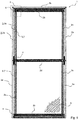
- Fig. 1 shows an insect screen swing door 1 constructed from profile strips.
- the insect screen swing door 1 comprises an inner profile frame, hereinafter referred to as door frame 2, which is composed of two longitudinal profiles 2a and two transverse profiles 2b, 2c in the frame corners.
- the lower transverse profile 2c can be made wider than the upper transverse profile 2b.
- the door frame 2 is inserted into an outer frame, referred to below as the holding frame 3, which is composed of two longitudinal profiles 3a and an (upper) transverse profile 3b is.
- the holding frame 3 can be inserted into a building opening (door opening or soffit of a building) and held (fastened) there, for example, in a non-destructive and detachable manner.
- the door frame 2 is articulated to the holding frame 3 by means of three spring-loaded door hinges 4 in the exemplary embodiment and is held in the holding frame 3 in a pivotable manner.
- the door hinges 4 are arranged on the mutually facing longitudinal profiles 2a and 3a of the door frame 2 or the holding frame 3 and fixed (fastened) there.
- the door frame 2 is also stabilized with a central transverse profile 2d.
- a mesh fabric 5 is used as an insect screen (clamped).
- At least one, preferably brush-like, sealing strips 7, which are held on the longitudinal profiles 3a of the holding frame 3, are inserted into the hinge-side gap 6 between the longitudinal profiles 2a and 3a of the door frame 2 or the holding frame 3. Further sealing strips 7 can be arranged between the upper transverse profiles 2b and 3b of the two profile frames 2 and 3 and on the lower transverse profile 2c of the door frame 2.
- the door frame 2 of the insect screen swing door 1 is held in a stable position by means of the door hinges 4 in the closed position shown and in both open positions, preferably at a 90 ° angle to the closed position, and can be pivoted back into the closed position.
- the spring-loaded door hinge 4 has a first hinge part (hinge) 8 and a second hinge part (hinge) 9 as well as a spring hinge 10 with a hinge pin 10a and with a spring pin 10b.
- the hinge pin 10a is assigned to the first hinge part 8, here on the holding frame side, which is mounted on the holding frame 3.
- the spring bolt 10b is assigned to the second hinge part 9, here on the door frame side, which is mounted on the door frame 2.
- the spring bolt 10b is rotatably coupled to the hinge bolt 10a and is oriented transversely to the latter.
- the hinge part 9 on the door frame side slides along a hinge contour 11 of the hinge part 9 on the holder frame side, generating a spring return force of the spring bolt 10b.
- the joint contour 11 is formed by rounded (convexly curved) edges of the hinge part 9 on the holding frame side.
- Both frames 2, 3 are composed of profile strips (hollow profile strips) and for this purpose are joined to one another in the frame corners by means of corner connectors 12.
- the longitudinal and transverse profiles 2a, 2b, 2c of the door frame 2 are connected in the two upper and the two lower frame corners by means of L-shaped corner connectors 12.
- rod-shaped profile connectors 13 are provided at the connection points of the longitudinal profiles 2a of the door frame 2 in the area of the central transverse profile 2d.
- rod-shaped profile connectors 14 are provided at the connection points of the longitudinal profiles 3a of the holding frame 3 in the area of the middle door hinge 4 ( Fig. 7 ).
- the door hinges 4 are arranged in the area of the corner connectors 12 and in the area of the profile connectors 13, 14. This achieves a particularly stable construction of the insect screen swing door 1, in that the corner connectors 12 and the profile connectors 13, 14 have the longitudinal profiles 2a, 3a stiffen at the appropriate points.
- the longitudinal profile 3a of the holding frame 3 has a longitudinal groove 15 in which the respective sealing element 7 is held.
- the (upper) transverse profile 3b also suitably has a (not visible) longitudinal groove in which the sealing element 7 there is held.
- the bolt axis of the spring bolt 10b runs perpendicular to the bolt axis of the hinge bolt 10a.
- the pin axis of the hinge pin 10a forms the axis of rotation of the spring pin 10b.
- the spring bolt 10b has, at the bolt end assigned to the hinge bolt 10a, a bolt opening 16 which is coaxial with the bolt axis of the hinge bolt 10a and which is penetrated by the hinge pin 10a. With this bolt end, the spring bolt 10b is guided through an opening 17 in the hinge part 9 on the door frame side and to the hinge bolt 10a in the hinge part 8 on the holding frame side.
- the spring bolt 10b carries a spring 18 in the form of a helical compression spring which surrounds the spring bolt 10b coaxially.
- the spring 18 is supported on the one hand on the door frame-side hinge part 9 and on the other hand on a bolt-fixed contact element in the form of a bolt head 19 on the free end of the spring bolt 10b opposite the bolt opening 16.
- the hinge part 8 on the holding frame side is a U-shaped hinge strap (hinge fitting).
- the two U-legs 8a serve as fastening legs on the holding frame 3.
- a screw bolt 20a with an external thread and a screw sleeve 20b with a corresponding internal thread are provided, which have corresponding openings 21, 22 in the U-legs 8a of the hinge as well as in the longitudinal profile 3a and in Reach through joining legs 12a of the corner connector 12 seated therein.
- the hinge part 8 on the holding frame side or its hinge band has the two joint contours 11 which are formed by rounded edges 23 on the plate-like band legs 8b of the hinge band connecting the U-legs 8a.
- the hinge part 8 on the support frame side has a pin channel 24 which receives the hinge pin 10a and has a hinge groove 25 through which the hinge pin 10a extends and in which the spring pin 10b is coupled to the hinge pin 10a.
- the hinge part 9 on the door frame side or its hinge has two openings, not shown in detail, for fixing screws 26.
- the hinge part or hinge 9 having the spring bolt 10b is fastened to the door frame 2 by means of the fixing screws 26.
- the longitudinal profile 2a of the door frame 2 has a joining chamber 27 in which a profile connector 28 is inserted for assembly with the associated transverse profile 2b.
- the profile connector 28 has a through-opening 28a for the spring bolt 10b and further through-opening 28b for the fixing screws 26 for corner mounting of the longitudinal and transverse profiles 2a, 2b.
- Its transverse profile 2b has a receiving chamber 30 for movably receiving the spring bolt 10b and joining chambers 31 for the fixing screws 26.
- the joining chambers 31 can be provided with an internal thread for screwing the fixing screws 26.
- the plate-like hinge or a corresponding hinge fitting of the door frame-side hinge part 9 in the form of a rectangular plate rests in the rest state with the insect screen swing door 1 closed on the holder frame-side hinge part 8 and there on its plate-like hinge leg 8b, the spring 18 of the spring bolt 10b being at least slightly tensioned .
- the spring bolt 10b pivots in the hinge groove 25 around the hinge bolt 10a of the hinge part 8 on the support frame side.
- the spring 18 is tensioned and the plate-like hinge of the hinge part 9 on the door frame side slides along the hinge contours 23 of the hinge part 8 on the support frame side .
- the insect screen swing door 1 swivels from the rest position (closed position) into the corresponding open position with further pretensioning of the spring 18.
- the insect screen swing door 1 assumes a further stable position, so it remains open in this position (automatically). This applies analogously to the open position of the insect screen swing door 1 in the opposite opening direction.
- the insect screen swing door 1 is actuated again (manually), it automatically swivels back into the closed position as a result of the spring return force.
- the invention relates to an insect screen swing door 1 with a holding frame 3 with a pivotable door frame 2 and with at least one spring-loaded door hinge 4 with a first and second Hinge part 8, 9, the door hinge 4 having a spring hinge 10 with a hinge pin 10a assigned to the first hinge part 8 and with a spring pin 10b assigned to the second hinge part 9 and rotatably coupled to the hinge pin 10a.
- the second hinge part 9 slides along a hinge contour 11, 23 of the first hinge part 8, generating a spring return force of the spring bolt 10b.
- the insect screen swing door 1 is as flat as possible.
- the width (profile width) of the holding frame 3 and the door frame 2 should be as small as possible.
- the width of the door hinge 4 is as small as possible and is preferably only (1.5 ⁇ 0.75) cm, in particular between 1.0 cm and 2.0 cm.
- the first hinge part 8 can also be arranged on the door frame 2 and the second hinge part 9 on the holding frame 3.
- the first hinge part 8 can only have a single, central tab or a corresponding leg, which is received in a corresponding longitudinal groove (receptacle) in the respective frame 2, 3 and, for example, is again fastened by means of screw bolts.
- Expanding dowels can also be provided instead of the joining chambers 31 in the transverse profile 2b of the door frame 2.
Landscapes
- Engineering & Computer Science (AREA)
- Structural Engineering (AREA)
- Civil Engineering (AREA)
- Mechanical Engineering (AREA)
- Life Sciences & Earth Sciences (AREA)
- Insects & Arthropods (AREA)
- Pest Control & Pesticides (AREA)
- Architecture (AREA)
- Specific Sealing Or Ventilating Devices For Doors And Windows (AREA)
- Catching Or Destruction (AREA)
Abstract
Description
- Die Erfindung betrifft eine Insektenschutz-Pendeltür mit einem Halterahmen zur Montage in einer Türlaibung oder in einem Türrahmen und mit einem schwenkbeweglichen Türrahmen sowie mit mindestens einem federbelasteten Türscharnier.
- Aus der
DE 20 2018 103 378 U1 ist eine als Pendeltür ausgeführte Insektenschutztür mit einem in eine Gebäudeöffnung oder in eine Türzarge einsetzbaren Halterahmen und mit einem Pendeltürahmen bekannt, der mit einem Gittergewebe bespannt ist. Zwischen den beiden Rahmen sind Scharniere vorgesehen, mittels derer der Türblatt-Rahmen am äußeren Rahmen angelenkt ist. Das jeweilige Türscharnier weist eine Scharnierachse und zwei Scharnierbänder mit schraubengangartigen Steuerkonturen und angeformten Fügeschenkeln sowie eine die Scharnierachse koaxial umgebende Feder (Spiralfeder) auf. - Beim Betätigen der Insektenschutz-Pendeltür verschwenken die türrahmenseitig gehaltenen Scharnierbuchsen gegenüber dem ortsfesten Scharnierband des Halterahmens, infolgedessen aufgrund der komplementären Steuerkonturen die innerhalb einer Fügekammer der entsprechenden Profilleiste verschiebbare Scharnierbuchse gegenüber der in der halterahmenseitigen Fügekammer fixierten Scharnierbuchse zwangsgeführt und dabei die Feder gespannt wird. Bei Aufhebung der Krafteinwirkung auf die Insektenschutz-Pendeltür erzeugt die gespannte Feder über die komplementären Steuerkonturen eine Federrückstellkraft auf die Scharnierbuchsen, sodass die Insektenschutz-Pendeltür aus der jeweiligen Offenposition automatisch in die Ausgangsposition (mittlere Schließstellung) zurückgeführt wird.
- Aus der
DE 100 34 071 A1 ist eine schwenkbar gelagerte Tür zum Verschließen einer Öffnung, insbesondere eine Fliegengittertür als Insektenschutz, mit einem Rahmen bekannt, welcher aus Aluminiumprofilen ausgebildet ist. Die bekannte Tür kann nach Art einer Pendeltür nach beiden Seiten geöffnet werden. Ein Torsionsstab, welcher in den Rahmen integriert oder an diesem angeordnet ist, dient als Rückstellvorrichtung, welche den Rahmen in die Ausgangsstellung zum Schließen der Öffnung bewegt. - Der Erfindung liegt die Aufgabe zugrunde, ein besonders geeignete Insektenschutz-Pendeltür anzugeben. Insbesondere soll ein zuverlässiges Verschwenken der Insektenschutz-Pendeltür ermöglicht sein. Zweckmäßigerweise soll ein automatisches Rückschwenken der Insektenschutz-Pendeltür aus einer Offenposition gegeben sein, wobei die Insektenschutz-Pendeltür vorzugsweise auch ohne, insbesondere magnetische, Schließteile zuverlässig in deren Schließstellung (Ruheposition) gehalten ist.
- Diese Aufgabe wird erfindungsgemäß mit den Merkmalen des Anspruchs 1 gelöst. Vorteilhafte Ausgestaltungen und Weiterbildungen sind Gegenstand der Unteransprüche.
- Die Insektenschutz-Pendeltür weist einen Halterahmen zur Montage in einer Türlaibung oder in einem Türrahmen und einen schwenkbeweglichen Türrahmen sowie mindestens ein federbelastetes Türscharnier auf, wobei der Türrahmen mittels des Türscharniers in der Schließstellung und in mindestens einer Offenstellung, insbesondere in beiden Offenstellungen, vorzugsweise in einem 90°-Winkel zur Schließstellung, in einer stabilen, in die Schließstellung rückschwenkbaren Lage gehalten ist.
- Das federbelastete Türscharnier weist ein erstes Scharnierteil (Scharnierband) und ein zweites Scharnierteil (Scharnierband) sowie ein Federgelenk mit einem Gelenkbolzen und mit einem Federbolzen auf. Der Gelenkbolzen ist dem ersten Scharnierteil zugeordnet, das zur Montage vorzugsweise am Halterahmen vorgesehen und eingerichtet ist. Der Federbolzen ist dem zweiten Scharnierteil zugeordnet, das zweckmäßigerweise zur Montage am Türrahmen vorgesehen und eingerichtet ist. Der Federbolzen ist mit dem Gelenkbolzen drehbeweglich gekoppelt, wobei im Zuge eines Verschwenkens des Türrahmens das zweite (türrahmenseitige) Scharnierteil entlang einer Gelenkkontur des ersten (halterahmenseitigen) Scharnierteils unter Erzeugung einer Federrückstellkraft des Federbolzens gleitet.
- Beide Rahmen sind aus Profilleisten (Hohlprofilleisten) zusammengesetzt. Hierzu sind geeigneter Weise in den Rahmenecken sogenannte Eckverbinder vorgesehen, welche im Montagezustand der Rahmen vorzugsweise in Fügekammern der Hohlprofilleisten einsitzen. Der Türrahmen ist aus Längsprofilen und Querprofilen zusammengesetzt und umfangsseitig geschlossen ausgeführt. Geeigneter Weise weist der Türrahmen ein oberes, ein unteres und ein mittleres Querprofil auf. Die Längs- und Querprofile sind in den beiden oberen und den beiden unteren Rahmenecken zweckmäßigerweise mittels L-förmigen Eckverbindern verbunden. An den Verbindungsstellen der Längsprofile im Bereich des mittleren Querprofils sind geeigneter Weise stabförmige Profilverbinder vorgesehen.
- Der Türrahmen ist dazu vorgesehen und eingerichtet, ein Gittergewebe aufzunehmen. Dieses ist zur Bildung einer Insektenschutztür mit dem entsprechenden Gitter (Gittergewebe) bespannt oder bespannbar. Hierzu sind zweckmäßiger Weise Kederleisten vorgesehen, die in entsprechende Kedernuten der Profile eingesetzt (eingepresst) werden.
- Der Halterahmen ist geeigneter Weise mittels zwei Längsprofilen und einem einzelnen, oberen Querprofil U-förmig, also umfangsseitig lediglich dreiseitig geschlossen ausgeführt. Zumindest an demjenigen Längsprofil, das dem Türrahmen an der Seite des Türscharniers zugewandten ist, ist ein Dichtelement, insbesondere eine Dichtbürste, vorgesehen. Hierzu weist das Längsprofil eine Längsnut auf, in welcher das Dichtelement gehalten ist. Analog weist geeigneter Weise auch das (obere) Querprofil eine Längsnut auf, in welcher ein Dichtelement gehalten ist. Hierdurch ist vermieden, dass Insekten oder dergleichen zwischen den beiden Rahmen hindurch gelangen können. Der Halterahmen ist dazu vorgesehen und eingerichtet, in eine Gebäude- oder Türöffnung oder in eine Türzarge oder dergleichen, bevorzugt zerstörungsfrei, eingesetzt und dort befestigt (gehalten) zu werden.
- In vorteilhafter Weiterbildung sind mindestens zwei, zweckmäßigerweise drei, federbelastete Türscharnier zwischen den beiden Rahmen (Halte- und Türrahmen) vorgesehen, mittels derer der (innere) Türrahmen mit dem Insektenschutz-Gitter oder Gittergewebe am (äußeren) Halterrahmen an einander gegenüberstehenden Längsprofilen angelenkt ist. Die Anordnung der Türscharniere erfolgt zweckmäßigerweise im Bereich der Eck- und/oder Profilverbinder, insbesondere des Halterahmens. Hierdurch wird eine besonders stabile Konstruktion der Insektenschutz-Pendeltür erreicht, indem die Eck- bzw. Profilverbinder die als Hohlprofile ausgeführten Längsprofile an den entsprechenden Stellen ausfüllen und somit versteifen.
- In vorteilhafter Ausgestaltung des jeweiligen Türscharniers ist die Bolzenachse des Federbolzens senkrecht zur Drehachse des Gelenkbolzens orientiert. Geeigneter Weise weist der Federbolzen eine zur Bolzenachse des Gelenkbolzen koaxiale Bolzenöffnung auf, die vom Gelenkbolzen durchsetzt ist. Die Bolzenöffnung ist zweckmäßigerweise am dem Gelenkbolzen zugeordneten Bolzenende des Federbolzens vorgesehen. Mit diesem Bolzenende ist der Federbolzen durch eine Öffnung im zweiten Scharnierteil zum Gelenkbolzen im ersten Scharnierteil geführt. Die Bolzenachse des Gelenkbolzen bildet die Drehachse des Federbolzens.
- Geeigneter Weise trägt der Federbolzen eine Feder, insbesondere eine Druckfeder. Die Feder ist vorteilhafterweise eine Spiralfeder ausgeführt, die beziehungsweise deren jede Federwindung den Federbolzen koaxial umgibt. Die Feder ist einerseits am zweiten Scharnierteil und andererseits an einem bolzenfesten Anlageelement abgestützt. Hierzu ist eine Lochscheibe und/oder ein Bolzenkopf am Freiende des Federbolzens vorgesehen.
- Das erste Scharnierteil ist geeigneter Weise U-förmiges, insbesondere ein U-förmiges Scharnierband. Die beiden U-Schenkel dienen zweckmäßigerweise als Befestigungsschenkel am Halterahmen, wozu die U-Schenkel den Halterahmen bzw. dessen entsprechendes Längsprofil zwischen sich aufnehmen. Hierzu ist vorteilhafterweise eine Schraubbefestigung vorgesehen, indem Schraubbolzen mit Innen- bzw. Außengewinde korrespondierende Öffnungen in den U-Schenkeln des Scharnierbands sowie im Längsprofil und im darin einsitzenden Fügeschenkel des Eckverbinders durchgreifen.
- Das erste Scharnierteil bzw. dessen Scharnierband weist mindestens eine Gelenkkontur auf. Diese ist vorzugsweise durch eine abgerundete Kante am die U-Schenkel verbindenden, plattenartigen Bandschenkel des Scharnierbandes gebildet. Geeigneter Weise sind zwei derartige Gelenkkonturen an gegenüberliegenden Seiten (Längsseiten) des vorzugsweise rechteckförmigen Bandschenkel des Scharnierbandes vorgesehen.
- Das erste Scharnierteil weist in zweckmäßiger Ausgestaltung einen den Gelenkbolzen aufnehmenden Bolzenkanal auf. Vorzugsweise weist der Bolzenkanal eine vom Gelenkbolzen durchsetze Gelenknut auf, in welche der Federbolzen eingreift bzw. in welcher der Federbolzen an den Gelenkbolzen gekoppelt ist. Das zweite Scharnierteil weist geeigneter Weise ein, insbesondere plattenartiges, Scharnierband mit einer Bolzenöffnung für den Federbolzen auf.
- Das Scharnierband des zweiten Scharnierteils weist mindestens eine Öffnung für den Federbolzen auf. Vorzugsweise sind zwei hierzu beabstandete Schraubenöffnungen für eine jeweilige Fixierschrauben vorgesehen. Mittels der Fixierschrauben wird das den Federbolzen aufweisende zweite Scharnierband am Türrahmen befestigt. Zumindest eines der Längsprofile des Türrahmens weist geeigneter Weise eine Fügekammer auf, in welcher ein Eck- oder Profilverbinder zur Montage mit einem zugeordneten Querprofil eingesetzt ist. Der Eck- oder Profilverbinder weist zweckmäßigerweise eine Durchgangsöffnungen für den Federbolzen und zumindest eine weitere Durchgangsöffnung für ein Fixierelement zur Eckmontage des Längs- und Querprofils auf. Das Querprofil weist eine Anzahl an Füge- oder Aufnahmekammern zur Aufnahme des Federbolzens und für die jeweilige Fixierschraube auf. Hierzu können die Fügekammern mit einem Innengewinde für die Verschraubung der Fixierschrauben versehen sein.
- Das plattenartige Scharnierband bzw. ein entsprechender Scharnierbeschlag des zweiten, türrahmenseitigen Scharnierteils in Form einer vorzugsweise rechteckförmigen Platte liegt im Ruhezustand bei geschlossener Insektenschutz-Pendeltür am ersten Scharnierteil und dort am plattenartigen Bandschenkel des Scharnierbandes an, wobei die Feder des Federbolzens vorzugsweise bereits zumindest geringfügig gespannt (vorgespannt) ist.
- Beim Verschwenken der Insektenschutz-Pendeltür schwenkt der Federbolzen in der Gelenknut um den Gelenkbolzen des ersten, halterahmenseitigen Scharnierteils, wobei die Feder zunehmend gespannt wird und das plattenartige Scharnierband des türrahmenseitigen Scharnierteils an den Gelenkkonturen des halterahmenseitigen Scharnierteils entlanggleitet. Auf diese Weise verschwenkt die Insektenschutz-Pendeltür aus der Ruhelage (Schließstellung) in die entsprechende Offenstellung unter weiterer Spannung der Feder.
- In einem Öffnungswinkel von etwa 90° nimmt die Insektenschutz-Pendeltür eine weitere stabile Lage ein, bleibt also in dieser Stellung offen. Dies gilt analog für die Offenstellung der Insektenschutz-Pendeltür in der entgegengesetzten Öffnungsrichtung. Durch erneute (manuelle) Betätigung der Insektenschutz-Pendeltür schwenkt diese in Folge der Federrückstellkraft selbsttätig in die Schließstellung zurück, praktisch ohne über diese hinaus zu in die andere Richtung zu schwingen. Es sind keine zusätzlichen Halteelemente, beispielsweise Magnete oder dergleichen, auf der den Türscharnieren abgewandten Längs- oder Vertikalseite der Insektenschutz-Pendeltür notwendig.
- Nachfolgend wird ein Ausführungsbeispiel der Erfindung anhand einer Zeichnung näher erläutert. Darin zeigen:
- Fig. 1
- in einer Vordereinsicht eine Insektenschutz-Pendeltür mit einem an einen Halterahmen über federbelastete Türscharniere angelenkten Türrahmen mit einem Insektenschutzgitter,
- Fig. 2
- in perspektivischer Darstellung einen Ausschnitt II aus
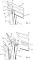
Figur 1 in der rechten oberen Rahmenecke in größerem Maßstab mit halterahmen- und türrahmenseitigen Längs- und Querprofilen (Profilleisten) sowie eines der Türscharniere mit einem halte- und türrahmenseitigen Scharnierteil (Scharnierband oder Scharnierbeschlag), - Fig. 3
- den Ausschnitt gemäß
Figur 2 in einer Explosionsdarstellung mit Blick auf einen halterahmenseitigen Eckverbinder und daran angeordnetem Scharnierteil sowie auf einen Federbolzen und Fixierschrauben des türrahmenseitigen Scharnierteils, - Fig. 4
- den Ausschnitt gemäß
Figur 2 in einer weiteren Explosionsdarstellung, - Fig. 5
- in einer Explosionsdarstellung die Scharnierteile mit an einen Gelenkbolzen angelenktem Federbolzen sowie mit einem türrahmenseitigen Eck- oder Profilverbinder,
- Fig. 6
- in perspektivischer Darstellung das federbelastete Türscharnier in einer 90°-Schwenkposition des türrahmenseitigen Scharnierteils gegenüber dem feststehenden halterahmenseitigen Scharnierteil, und
- Fig. 7
- in einer Explosionsdarstellung ein weiteres Türscharnier im Bereich eines mittleren Querprofils mit dortigen Verbindungsstangen für die halte- und türrahmenseitigen Längsprofile.
- Einander entsprechende Teile sind in allen Figuren mit den gleichen Bezugszeichen versehen.
-
Fig. 1 zeigt eine aus Profilleisten aufgebaute Insektenschutz-Pendeltür 1. Die Insektenschutz-Pendeltür 1 umfasst einen nachfolgend als Türrahmen 2 bezeichneten inneren Profilrahmen, der aus zwei Längsprofilen 2a und zwei Querprofilen 2b, 2c in den Rahmenecken zusammengesetzt ist. Das untere Querprofil 2c kann breiter als das obere Querprofil 2b ausgeführt sein. Der Türrahmen 2 ist in einen nachfolgend als Halterahmen 3 bezeichneten äußeren Rahmen eingesetzt, welcher aus zwei Längsprofilen 3a sowie einem (oberen) Querprofil 3b zusammengesetzt ist. Der Halterahmen 3 kann in einer Gebäudeöffnung (Türöffnung oder - Laibung eines Gebäudes) eingesetzt und dort beispielsweise zerstörungsfrei und lösbar gehalten (befestigt) sein. - Der Türrahmen 2 ist an den Halterahmen 3 mittels im Ausführungsbeispiel drei federbelasteten Türscharnieren 4 angelenkt und im Halterahmen 3 schwenkbeweglich gehalten. Hierzu sind die Türscharnieren 4 an den einander zugewandten Längsprofilen 2a und 3a des Türrahmens 2 bzw. des Halterahmens 3 angeordnet und dort fixiert (befestigt). Der Türrahmen 2 ist zudem mit einem mittleren Querprofil 2d stabilisiert. In den Türrahmen 2 bzw. in dessen beiden Türfächer ist ein Gittergewebe 5 als Insektenschutz eingesetzt (eingespannt). In den scharnierseitigen Spalt 6 zwischen den Längsprofilen 2a und 3a des Türrahmens 2 bzw. des Halterahmens 3 ist mindestens eine, vorzugsweise bürstenartige, Dichtleisten 7 eingesetzt, welche an den Längsprofilen 3a des Halterahmens 3 gehalten sind. Weitere Dichtleisten 7 können zwischen den oberen Querprofilen 2b und 3b der beiden Profilrahmen 2 bzw. 3 sowie am untern Querprofil 2c des Türrahmens 2 angeordnet sein.
- Der Türrahmen 2 der Insektenschutz-Pendeltür 1 ist mittels der Türscharniere 4 in der gezeigten Schließstellung und in beiden Offenstellung, vorzugsweise in einem 90°-Winkel zur Schließstellung, in einer stabilen Lage gehalten sowie in die Schließstellung rückschwenkbar.
- Wie aus den
Figuren 2 bis 5 ersichtlich ist, weist das federbelastete Türscharnier 4 ein erstes Scharnierteil (Scharnierband) 8 und ein zweites Scharnierteil (Scharnierband) 9 sowie ein Federgelenk 10 mit einem Gelenkbolzen 10a und mit einem Federbolzen 10b auf. Der Gelenkbolzen 10a ist dem ersten, hier halterahmenseitigen Scharnierteil 8 zugeordnet, das am Halterahmen 3 montieret ist. Der Federbolzen 10b ist dem zweiten, hier türrahmenseitigen Scharnierteil 9 zugeordnet, das am Türrahmen 2 montieret ist. Der Federbolzen 10b ist mit dem Gelenkbolzen 10a drehbeweglich gekoppelt und quer zu diesem orientiert. - Im Zuge eines Verschwenkens des Türrahmens 2 gegenüber dem feststehenden Halterahmen 3, d. h. aus diesem heraus, gleitet das türrahmenseitige Scharnierteil 9 entlang einer Gelenkkontur 11 des halterahmenseitigen Scharnierteil 9 unter Erzeugung einer Federrückstellkraft des Federbolzens 10b. Die Gelenkkontur 11 ist durch gerundete (konvex gewölbte) Kanten des halterahmenseitigen Scharnierteil 9 gebildet.
- Beide Rahmen 2, 3 sind aus Profilleisten (Hohlprofilleisten) zusammengesetzt und hierzu in den Rahmenecken mittels Eckverbinder 12 miteinander gefügt. Die Längs- und Querprofile 2a, 2b, 2c des Türrahmens 2 sind in den beiden oberen und den beiden unteren Rahmenecken mittels L-förmigen Eckverbinder 12 verbunden. An den Verbindungsstellen der Längsprofile 2a des Türrahmens 2 sind im Bereich des mittleren Querprofils 2d stabförmige Profilverbinder 13 vorgesehen. Analog sind an den Verbindungsstellen der Längsprofile 3a des Halterahmens 3 im Bereich des mittleren Türscharniers 4 stabförmige Profilverbinder 14 vorgesehen (
Fig. 7 ). - Die Anordnung der Türscharniere 4 erfolgt im Bereich der Eckverbinder 12 und im Bereich der Profilverbinder 13, 14. Hierdurch wird eine besonders stabile Konstruktion der Insektenschutz-Pendeltür 1 erreicht, indem die Eckverbinder 12 und die Profilverbinder 13, 14 die als Hohlprofile ausgeführten Längsprofile 2a, 3a an den entsprechenden Stellen versteifen.
- Wie aus
Fig. 3 vergleichsweise deutlich ersichtlich ist, weist das Längsprofil 3a des Halterahmens 3 eine Längsnut 15 auf, in welcher das jeweilige Dichtelement 7 gehalten ist. Analog weist geeigneter Weise auch das (obere) Querprofil 3b eine (nicht sichtbare) Längsnut auf, in welcher das dortige Dichtelement 7 gehalten ist. - Wie aus
Fig. 5 vergleichsweise deutlich ersichtlich ist, verläuft die Bolzenachse des Federbolzens 10b senkrecht zur Bolzenachse des Gelenkbolzens 10a. Die Bolzenachse des Gelenkbolzen 10a bildet die Drehachse des Federbolzens 10b. Der Federbolzen 10b weist am dem Gelenkbolzen 10a zugeordneten Bolzenende eine zur Bolzenachse des Gelenkbolzen 10a koaxiale Bolzenöffnung 16 auf, die vom Gelenkbolzen 10a durchsetzt ist. Mit diesem Bolzenende ist der Federbolzen 10b durch eine Öffnung 17 im türrahmenseitigen Scharnierteil 9 und zum Gelenkbolzen 10a im halterahmenseitigen Scharnierteil 8 geführt. - Der Federbolzen 10b trägt eine Feder 18 in Form einer spiralförmigen Druckfeder, welche den Federbolzen 10b koaxial umgibt. Die Feder 18 ist einerseits am türrahmenseitigen Scharnierteil 9 und andererseits an einem bolzenfesten Anlageelement in Form eines Bolzenkopfes 19 am der Bolzenöffnung 16 gegenüberliegenden Freiende des Federbolzens 10b abgestützt.
- Das halterahmenseitige Scharnierteil 8 ist ein U-förmiges Scharnierband (Scharnierbeschlag). Die beiden U-Schenkel 8a dienen als Befestigungsschenkel am Halterahmen 3. Hierzu sind ein Schraubbolzen 20a mit einem Außengewinde und eine Schraubhülse 20b mit korrespondierendem Innengewinde vorgesehen, welche korrespondierende Öffnungen 21, 22 in den U-Schenkeln 8a des Scharnierbands sowie im Längsprofil 3a und im darin einsitzenden Fügeschenkel 12a des Eckverbinders 12 durchgreifen.
- Das halterahmenseitige Scharnierteil 8 bzw. dessen Scharnierband weist die beiden Gelenkkonturen 11 auf, welche durch abgerundete Kanten 23 am die U-Schenkel 8a verbindenden, plattenartigen Bandschenkel 8b des Scharnierbandes gebildet sind. Das halterahmenseitige Scharnierteil 8 weist einen den Gelenkbolzen 10a aufnehmenden Bolzenkanal 24 mit einer vom Gelenkbolzen 10a durchsetze Gelenknut 25 auf, in welcher der Federbolzen 10b an den Gelenkbolzen 10a gekoppelt ist.
- Das türrahmenseitigen Scharnierteils 9 bzw. dessen Scharnierband weist zwei nicht näher bezeichnete Öffnungen für Fixierschrauben 26 auf. Mittels der Fixierschrauben 26 wird das den Federbolzen 10b aufweisende Scharnierteils oder Scharnierband 9 am Türrahmen 2 befestigt. Hierzu weist das Längsprofile 2a des Türrahmens 2 eine Fügekammer 27 auf, in welcher ein Profilverbinder 28 zur Montage mit dem zugeordneten Querprofil 2b eingesetzt ist. Der Profilverbinder 28 weist eine Durchgangsöffnungen 28a für den Federbolzen 10b und weitere Durchgangsöffnung 28b für die Fixierschrauben 26 zur Eckmontage des Längs- und Querprofils 2a, 2b auf. Hiermit korrespondieren entsprechende Öffnungen 29a, 29b im Längsprofil 2a des Türrahmens 2. Dessen Querprofil 2b weist eine Aufnahmekammer 30 zur beweglichen Aufnahme des Federbolzens 10b und Fügekammern 31 für die Fixierschrauben 26 auf. Hierzu können die Fügekammern 31 mit einem Innengewinde für die Verschraubung der Fixierschrauben 26 versehen sein.
- Das plattenartige Scharnierband bzw. ein entsprechender Scharnierbeschlag des türrahmenseitigen Scharnierteils 9 in Form einer rechteckförmigen Platte liegt im Ruhezustand bei geschlossener Insektenschutz-Pendeltür 1 am halterahmenseitigen Scharnierteil 8 und dort an dessen plattenartigen Bandschenkel 8b an, wobei die Feder 18 des Federbolzens 10b zumindest geringfügig gespannt ist.
- Wie anhand der
Fig. 6 veranschaulicht, schwenkt beim Öffnen der Insektenschutz-Pendeltür 1 der Federbolzen 10b in der Gelenknut 25 um den Gelenkbolzen 10a des halterahmenseitigen Scharnierteils 8. Dabei wird die Feder 18 gespannt und das plattenartige Scharnierband des türrahmenseitigen Scharnierteils 9 gleitet an den Gelenkkonturen 23 des halterahmenseitigen Scharnierteils 8 entlang. Auf diese Weise verschwenkt die Insektenschutz-Pendeltür 1 aus der Ruhelage (Schließstellung) in die entsprechende Offenstellung unter weiterer Vorspannung der Feder 18. - In einem Öffnungswinkel von 90° nimmt die Insektenschutz-Pendeltür 1 eine weitere stabile Lage ein, bleibt also in dieser Stellung (selbsttätig) offen. Dies gilt analog für die Offenstellung der Insektenschutz-Pendeltür 1 in der entgegengesetzten Öffnungsrichtung. Durch erneute (manuelle) Betätigung der Insektenschutz-Pendeltür 1 schwenkt diese in Folge der Federrückstellkraft selbsttätig in die Schließstellung zurück.
- Zusammenfassend betrifft die Erfindung eine Insektenschutz-Pendeltür 1 mit einem Halterahmen 3 mit einem schwenkbeweglichen Türrahmen 2 sowie mit mindestens einem federbelasteten Türscharnier 4 mit einem ersten und zweiten Scharnierteil 8, 9, wobei das Türscharnier 4 ein Federgelenk 10 mit einem dem ersten Scharnierteil 8 zugeordneten Gelenkbolzen 10a und mit einem dem zweiten Scharnierteil 9 zugeordneten, mit dem Gelenkbolzen 10a drehbeweglich gekoppelten Federbolzen 10b aufweist. Im Zuge eines Verschwenkens des Türrahmens 2 gleitet das zweite Scharnierteil 9 entlang einer Gelenkkontur 11, 23 des ersten Scharnierteils 8 unter Erzeugung einer Federrückstellkraft des Federbolzens 10b.
- Es ist wünschenswert, dass die Insektenschutz-Pendeltür 1 möglichst flach ist. Mit anderen Worten sollen die Breite (Profilbreite) des Halterahmens 3 und des Türrahmens 2 möglichst gering sein. Dem folgend ist die Breit des Türscharniers 4 möglichst gering und beträgt vorzugsweise lediglich (1,5 ± 0,75) cm, insbesondere zwischen 1,0 cm und 2,0 cm.
- Die beanspruchte Erfindung ist nicht auf das vorstehend beschriebene Ausführungsbeispiel beschränkt. Vielmehr können auch andere Varianten der Erfindung von dem Fachmann hieraus im Rahmen der offenbarten Ansprüche abgeleitet werden, ohne den Gegenstand der beanspruchten Erfindung zu verlassen. Insbesondere sind ferner alle im Zusammenhang mit den verschiedenen Ausführungsbeispielen beschriebenen Einzelmerkmale im Rahmen der offenbarten Ansprüche auch auf andere Weise kombinierbar, ohne den Gegenstand der beanspruchten Erfindung zu verlassen.
- So kann das erste Scharnierteil 8 auch am Türrahmen 2 und das zweite Scharnierteil 9 am Halterahmen 3 angeordnet sein. Zudem kann das erste Scharnierteil 8 lediglich eine einzelne, mittlere Lasche oder einen entsprechenden Schenkel aufweisen, die bzw. der in eine korrespondierenden Längsnut (Aufnahme) im jeweiligen Rahmen 2, 3 aufgenommen und beispielsweise wiederum mittels Schraubbolzen befestigt ist. Auch können Spreizdübel anstelle der Fügekammern 31 im Querprofil 2b des Türrahmens 2 vorgesehen sein.
-
- 1
- Insektenschutz-Pendeltür
- 2
- Türrahmen
- 2a
- Längsprofil/Profilleiste
- 2b
- oberes Querprofil/ Profilleiste
- 2c
- unteres Querprofil/ Profilleiste
- 2d
- mittleres Querprofil/ Profilleiste
- 3
- Halterahmen
- 3a
- Längsprofil/Profilleiste
- 3b
- oberes Querprofil/Profilleiste
- 4
- Türscharnier
- 5
- Gittergewebe
- 6
- Spalt
- 7
- Dichtleiste
- 8
- erstes Scharnierteil/-band
- 8a
- U- Schenkel
- 8b
- Bandschenkel
- 9
- zweites Scharnierteil/-band
- 10
- Federgelenk
- 10a
- Gelenkbolzen
- 10b
- Federbolzen
- 11
- Gelenkkontor
- 12
- Eckverbinder
- 12a
- Fügeschenkel
- 13,14
- Profilverbinder
- 15
- Längsnut
- 16
- Bolzenöffnung
- 17
- Öffnung
- 18
- Feder/Spiral-/Druckfeder
- 19
- Bolzenkopf
- 20a
- Schraubbolzen
- 20b
- Schraubhülse
- 21,22
- Öffnung
- 23
- gerundete Kante
- 24
- Bolzenkanal
- 25
- Gelenknut
- 26
- Fixierschraube
- 27
- Fügekammer
- 28a,b
- Durchgangsöffnung
- 29a,b
- Öffnung
- 30
- Aufnahmekammer
- 31
- Fügekammer
Claims (15)
- Insektenschutz-Pendeltür (1) mit einem Halterahmen (3) zur Montage in einer Türlaibung oder in einem Türrahmen und mit einem schwenkbeweglichen Türrahmen (2), der aus Längsprofilen (2a) und Querprofilen (2b, 2c, 2d) zusammengesetzt ist, sowie mit mindestens einem federbelasteten Türscharnier (4) mit einem ersten Scharnierteil (8) und mit einem zweiten Scharnierteil (9),
dadurch gekennzeichnet,- dass das Türscharnier (4) ein Federgelenk (10) mit einem dem ersten Scharnierteil (8) zugeordneten Gelenkbolzen (10a) und mit einem dem zweiten Scharnierteil (9) zugeordneten Federbolzen (10b) aufweist, der mit dem Gelenkbolzen (10a) drehbeweglich gekoppelt ist, wobei im Zuge eines Verschwenkens des Türrahmens (2) das zweite Scharnierteil (9) entlang einer Gelenkkontur (11, 23) des ersten Scharnierteils (8) unter Erzeugung einer Federrückstellkraft des Federbolzens (10b) gleitet. - Insektenschutz-Pendeltür (1) nach Anspruch 1,
dadurch gekennzeichnet,- dass die Bolzenachse des Federbolzens (10b) senkrecht zur Dreh- oder Bolzenachse des Gelenkbolzens (10a) orientiert ist, und/oder- dass der Federbolzen (10b), insbesondere am dem Gelenkbolzen (10a) zugeordneten Bolzenende, eine zur Bolzenachse des Gelenkbolzens (10a) koaxiale Bolzenöffnung (16) aufweist, die vom Gelenkbolzen (10a) durchsetzt ist. - Insektenschutz-Pendeltür (1) nach Anspruch 1 oder 2,
dadurch gekennzeichnet,
dass der Federbolzen (10b) eine Feder (18), insbesondere eine Druckfeder, trägt. - Insektenschutz-Pendeltür (1) nach Anspruch 3,
dadurch gekennzeichnet,
dass die Feder (18) einerseits am zweiten Scharnierteil (9) und andererseits an einem bolzenfesten Anlageelement (19) abgestützt ist. - Insektenschutz-Pendeltür (1) nach einem der Ansprüche 1 bis 4,
dadurch gekennzeichnet,
dass das erste Scharnierteil (8) dem Halterahmen (3) und das zweite Scharnierteil (9) dem Türrahmen (2) zugeordnet ist. - Insektenschutz-Pendeltür (1) nach einem der Ansprüche 1 bis 5,
dadurch gekennzeichnet,
dass das erste Scharnierteil (8) ein, insbesondere U-förmiges, Scharnierband mit mindestens einer Gelenkkontur (11, 23) aufweist. - Insektenschutz-Pendeltür (1) nach einem der Ansprüche 1 bis 5,
dadurch gekennzeichnet,
dass das erste Scharnierteil (8) einen den Gelenkbolzen (10a) aufnehmenden Bolzenkanal (24) aufweist. - Insektenschutz-Pendeltür (1) nach Anspruch 7,
dadurch gekennzeichnet,
dass der Bolzenkanal (16) eine vom Gelenkbolzen (10a) durchsetze Gelenknut (25) aufweist, in welcher der Federbolzen (10b) an den Gelenkbolzen (10a) gekoppelt ist. - Insektenschutz-Pendeltür (1) nach einem der Ansprüche 1 bis 8,
dadurch gekennzeichnet,
dass das zweite Scharnierteil (9) eine Bolzenöffnung (17) für den Federbolzen (10b) aufweist. - Insektenschutz-Pendeltür (1) nach einem der Ansprüche 1 bis 9,
dadurch gekennzeichnet,
dass der Halterahmen (3) mindestens ein Längsprofil (3a) und ein mit diesem über einen Eckverbinder (12) gefügtes Querprofil (3b) aufweist. - Insektenschutz-Pendeltür (1) nach Anspruch 10,
dadurch gekennzeichnet,
dass das erste Scharnierband (8) im Bereich des Eckverbinders (12) mit dem Längsprofil (3a) verbunden ist. - Insektenschutz-Pendeltür (1) nach einem der Ansprüche 1 bis 11,
dadurch gekennzeichnet,
dass der Türrahmen (2) aus Längsprofilen (2a) und Querprofilen (b, 2c, 2d) zusammengesetzt ist. - Insektenschutz-Pendeltür (1) nach Anspruch 12,
dadurch gekennzeichnet,
dass zumindest eines der Längsprofile (2a) eine Fügekammer (27) aufweist, in welcher ein Profilverbinder (28) zur Montage mit einem zugeordneten Querprofil (2b, 2c, 2d) mit einer Anzahl an Füge- oder Aufnahmekammern (30, 31) eingesetzt ist. - Insektenschutz-Pendeltür (1) nach Anspruch 13,
dadurch gekennzeichnet,
dass der Profilverbinder (28) eine Durchgangsöffnungen (28a) für den Federbolzen (10b) und zumindest eine weitere Durchgangsöffnung (28b) für ein Fixierelement (26) zur Eckmontage des Längs- und Querprofils (2a, 2b, 2c, 2d) aufweist. - Insektenschutz-Pendeltür (1) mit einem Halterahmen (3) zur Montage in einer Türlaibung oder in einem Türrahmen und mit einem schwenkbeweglichen Türrahmen (2) sowie mit mindestens einem federbelasteten Türscharnier (4), insbesondere nach einem der Ansprüche 1 bis 14, wobei der Türrahmen (2) mittels des Türscharniers (4) in der Schließstellung und in mindestens einer Offenstellung, insbesondere in beiden Offenstellungen, vorzugsweise in einem 90°-Winkel zur Schließstellung, in einer stabilen, in die Schließstellung rückschwenkbaren Lage gehalten ist.
Applications Claiming Priority (1)
| Application Number | Priority Date | Filing Date | Title |
|---|---|---|---|
| DE202020102300.4U DE202020102300U1 (de) | 2020-04-24 | 2020-04-24 | Insektenschutz-Pendeltür |
Publications (4)
| Publication Number | Publication Date |
|---|---|
| EP3901401A2 true EP3901401A2 (de) | 2021-10-27 |
| EP3901401A3 EP3901401A3 (de) | 2022-02-23 |
| EP3901401B1 EP3901401B1 (de) | 2023-07-19 |
| EP3901401C0 EP3901401C0 (de) | 2023-07-19 |
Family
ID=70858517
Family Applications (1)
| Application Number | Title | Priority Date | Filing Date |
|---|---|---|---|
| EP21169816.2A Active EP3901401B1 (de) | 2020-04-24 | 2021-04-22 | Insektenschutz-pendeltür |
Country Status (2)
| Country | Link |
|---|---|
| EP (1) | EP3901401B1 (de) |
| DE (1) | DE202020102300U1 (de) |
Cited By (1)
| Publication number | Priority date | Publication date | Assignee | Title |
|---|---|---|---|---|
| EP4647571A1 (de) | 2024-05-08 | 2025-11-12 | Cofano, Giuseppe | Pendelscharnier |
Citations (2)
| Publication number | Priority date | Publication date | Assignee | Title |
|---|---|---|---|---|
| DE10034071A1 (de) | 1999-07-14 | 2001-03-29 | Eberhard Waldenmaier | Einrichtung zum Verschließen einer Öffnung |
| DE202018103378U1 (de) | 2018-06-15 | 2019-09-17 | M.A.C.'s Holding Gmbh | Scharnier sowie Pendeltür |
Family Cites Families (8)
| Publication number | Priority date | Publication date | Assignee | Title |
|---|---|---|---|---|
| GB191307534A (en) * | 1913-03-31 | 1914-03-26 | Paul Mcintosh Smith | Improvements in Spring Hinges. |
| GB191317080A (en) * | 1913-07-25 | 1914-05-21 | Edgar Godwin Harcourt | Improvements relating to Spring Hinges. |
| GB804584A (en) * | 1956-03-14 | 1958-11-19 | Walter Rowley Ltd | Door hinges |
| FR2343111A1 (fr) * | 1976-03-01 | 1977-09-30 | Adler Sa | Charniere |
| US5077864A (en) * | 1990-12-27 | 1992-01-07 | Junzaburo Kawasaki | Swing door hinge |
| DE19603770A1 (de) * | 1996-02-02 | 1997-08-07 | Winkhaus Fa August | Fenster, Tür oder dergleichen mit Beschlagsystem |
| DE102007020730A1 (de) * | 2007-05-03 | 2008-11-06 | Wolfgang Melz | Pendeltür mit Selbstschließscharnier |
| DE202014005807U1 (de) * | 2014-07-16 | 2015-10-21 | Ips Insect Protect Systems Gmbh | Profilrahmensystem eines Insekten- bzw. Pollenschutzgitters |
-
2020
- 2020-04-24 DE DE202020102300.4U patent/DE202020102300U1/de active Active
-
2021
- 2021-04-22 EP EP21169816.2A patent/EP3901401B1/de active Active
Patent Citations (2)
| Publication number | Priority date | Publication date | Assignee | Title |
|---|---|---|---|---|
| DE10034071A1 (de) | 1999-07-14 | 2001-03-29 | Eberhard Waldenmaier | Einrichtung zum Verschließen einer Öffnung |
| DE202018103378U1 (de) | 2018-06-15 | 2019-09-17 | M.A.C.'s Holding Gmbh | Scharnier sowie Pendeltür |
Cited By (2)
| Publication number | Priority date | Publication date | Assignee | Title |
|---|---|---|---|---|
| EP4647571A1 (de) | 2024-05-08 | 2025-11-12 | Cofano, Giuseppe | Pendelscharnier |
| DE102024112915A1 (de) * | 2024-05-08 | 2025-11-13 | Giuseppe Cofano | Pendelscharnier |
Also Published As
| Publication number | Publication date |
|---|---|
| DE202020102300U1 (de) | 2020-05-07 |
| EP3901401A3 (de) | 2022-02-23 |
| EP3901401B1 (de) | 2023-07-19 |
| EP3901401C0 (de) | 2023-07-19 |
Similar Documents
| Publication | Publication Date | Title |
|---|---|---|
| DE3502175C2 (de) | ||
| AT6962U1 (de) | Scharnier | |
| DE4219681C2 (de) | Einstellbares Abhebescharnier | |
| DE102019207938B4 (de) | Insektenschutztür, insbesondere Insektenschutz-Pendeltür, sowie Türscharnier hierfür | |
| DE3626451A1 (de) | Beschlagteil zur klemmbefestigung an profilen | |
| EP3901401B1 (de) | Insektenschutz-pendeltür | |
| DE3843680A1 (de) | Beschlag fuer tueren, fenster oder dergleichen | |
| DE3329414A1 (de) | Einhand-drehkipp-beschlag fuer ein fenster | |
| DE102019106099B4 (de) | Insektenschutztür | |
| EP2320022B1 (de) | Scharnier für ein Insekten- und/oder Pollenschutzgitter | |
| EP1898041B1 (de) | Vorrichtung und Verfahren zum Befestigen von Aufsatzelementen auf bauseitigen Rahmensystemen | |
| DE102008036151A1 (de) | Scharnierband mit einer Unterkonstruktion zur Befestigung an einem Türblatt | |
| EP4045744B1 (de) | Beschlaganordnung | |
| DE19758907B4 (de) | Einen Überschlag aufweisender Flügel eines Fensters, einer Tür oder dergleichen, mit einem Scharnierbeschlag sowie Montageverfahren des Scharnierbeschlags | |
| EP2634342B1 (de) | Antrieb für einen Flügel eines Fensters oder dergleichen sowie ein Verfahren zur Montage des Antriebs | |
| EP1449988B1 (de) | Rastmodul für Fenster- und/oder Türbeschläge | |
| EP1777363B1 (de) | Vorrichtung zum Arretieren einer Tür eines Gehäuses | |
| DE102012106191B4 (de) | Vorspannbauteil für eine Fenster- oder Türvorrichtung und Fenster- oder Türvorrichtung | |
| DE60000569T2 (de) | Scharnierbeschlag für Tür, Fenster oder dergleichen | |
| DE202009003379U1 (de) | Beschlaganordnung und Fenster oder Tür mit einer solchen Beschlaganordnung | |
| EP4375463A1 (de) | Beschlagsteil | |
| DE10235609B4 (de) | Beschlag zwischen einem festen Rahmen und einem gegenüber diesem wenigstens kippbaren Flügel eines Fensters, einer Tür oder dergleichen | |
| DE20217852U1 (de) | Band für Türen, Fenster o.dgl. | |
| DE202025103314U1 (de) | Insektenschutztür sowie Türscharnier hierfür | |
| DE202023101015U1 (de) | Torband für einen Torflügel, Bausatz mit wenigstens zwei Torbändern, Toranordnung mit einem Torflügel und mit den Torbändern des Bausatzes und Zaun mit der Toranordnung |
Legal Events
| Date | Code | Title | Description |
|---|---|---|---|
| PUAI | Public reference made under article 153(3) epc to a published international application that has entered the european phase |
Free format text: ORIGINAL CODE: 0009012 |
|
| STAA | Information on the status of an ep patent application or granted ep patent |
Free format text: STATUS: THE APPLICATION HAS BEEN PUBLISHED |
|
| AK | Designated contracting states |
Kind code of ref document: A2 Designated state(s): AL AT BE BG CH CY CZ DE DK EE ES FI FR GB GR HR HU IE IS IT LI LT LU LV MC MK MT NL NO PL PT RO RS SE SI SK SM TR |
|
| PUAL | Search report despatched |
Free format text: ORIGINAL CODE: 0009013 |
|
| STAA | Information on the status of an ep patent application or granted ep patent |
Free format text: STATUS: REQUEST FOR EXAMINATION WAS MADE |
|
| AK | Designated contracting states |
Kind code of ref document: A3 Designated state(s): AL AT BE BG CH CY CZ DE DK EE ES FI FR GB GR HR HU IE IS IT LI LT LU LV MC MK MT NL NO PL PT RO RS SE SI SK SM TR |
|
| RIC1 | Information provided on ipc code assigned before grant |
Ipc: E05D 5/02 20060101ALI20220117BHEP Ipc: E05D 15/54 20060101ALI20220117BHEP Ipc: E05F 1/12 20060101ALI20220117BHEP Ipc: E06B 9/52 20060101ALI20220117BHEP Ipc: E06B 3/968 20060101ALI20220117BHEP Ipc: E06B 3/964 20060101ALI20220117BHEP Ipc: E05D 11/10 20060101AFI20220117BHEP |
|
| 17P | Request for examination filed |
Effective date: 20220128 |
|
| RBV | Designated contracting states (corrected) |
Designated state(s): AL AT BE BG CH CY CZ DE DK EE ES FI FR GB GR HR HU IE IS IT LI LT LU LV MC MK MT NL NO PL PT RO RS SE SI SK SM TR |
|
| STAA | Information on the status of an ep patent application or granted ep patent |
Free format text: STATUS: EXAMINATION IS IN PROGRESS |
|
| 17Q | First examination report despatched |
Effective date: 20220421 |
|
| GRAP | Despatch of communication of intention to grant a patent |
Free format text: ORIGINAL CODE: EPIDOSNIGR1 |
|
| STAA | Information on the status of an ep patent application or granted ep patent |
Free format text: STATUS: GRANT OF PATENT IS INTENDED |
|
| INTG | Intention to grant announced |
Effective date: 20220719 |
|
| RAP3 | Party data changed (applicant data changed or rights of an application transferred) |
Owner name: MACS HOLDING GMBH |
|
| GRAJ | Information related to disapproval of communication of intention to grant by the applicant or resumption of examination proceedings by the epo deleted |
Free format text: ORIGINAL CODE: EPIDOSDIGR1 |
|
| STAA | Information on the status of an ep patent application or granted ep patent |
Free format text: STATUS: EXAMINATION IS IN PROGRESS |
|
| INTC | Intention to grant announced (deleted) | ||
| GRAP | Despatch of communication of intention to grant a patent |
Free format text: ORIGINAL CODE: EPIDOSNIGR1 |
|
| STAA | Information on the status of an ep patent application or granted ep patent |
Free format text: STATUS: GRANT OF PATENT IS INTENDED |
|
| INTG | Intention to grant announced |
Effective date: 20230316 |
|
| GRAS | Grant fee paid |
Free format text: ORIGINAL CODE: EPIDOSNIGR3 |
|
| GRAA | (expected) grant |
Free format text: ORIGINAL CODE: 0009210 |
|
| STAA | Information on the status of an ep patent application or granted ep patent |
Free format text: STATUS: THE PATENT HAS BEEN GRANTED |
|
| AK | Designated contracting states |
Kind code of ref document: B1 Designated state(s): AL AT BE BG CH CY CZ DE DK EE ES FI FR GB GR HR HU IE IS IT LI LT LU LV MC MK MT NL NO PL PT RO RS SE SI SK SM TR |
|
| REG | Reference to a national code |
Ref country code: GB Ref legal event code: FG4D Free format text: NOT ENGLISH |
|
| REG | Reference to a national code |
Ref country code: CH Ref legal event code: EP |
|
| REG | Reference to a national code |
Ref country code: DE Ref legal event code: R096 Ref document number: 502021001025 Country of ref document: DE |
|
| REG | Reference to a national code |
Ref country code: IE Ref legal event code: FG4D Free format text: LANGUAGE OF EP DOCUMENT: GERMAN |
|
| U01 | Request for unitary effect filed |
Effective date: 20230726 |
|
| U07 | Unitary effect registered |
Designated state(s): AT BE BG DE DK EE FI FR IT LT LU LV MT NL PT SE SI Effective date: 20230801 |
|
| REG | Reference to a national code |
Ref country code: LT Ref legal event code: MG9D |
|
| PG25 | Lapsed in a contracting state [announced via postgrant information from national office to epo] |
Ref country code: IS Free format text: LAPSE BECAUSE OF FAILURE TO SUBMIT A TRANSLATION OF THE DESCRIPTION OR TO PAY THE FEE WITHIN THE PRESCRIBED TIME-LIMIT Effective date: 20231119 |
|
| PG25 | Lapsed in a contracting state [announced via postgrant information from national office to epo] |
Ref country code: RS Free format text: LAPSE BECAUSE OF FAILURE TO SUBMIT A TRANSLATION OF THE DESCRIPTION OR TO PAY THE FEE WITHIN THE PRESCRIBED TIME-LIMIT Effective date: 20230719 Ref country code: NO Free format text: LAPSE BECAUSE OF FAILURE TO SUBMIT A TRANSLATION OF THE DESCRIPTION OR TO PAY THE FEE WITHIN THE PRESCRIBED TIME-LIMIT Effective date: 20231019 Ref country code: IS Free format text: LAPSE BECAUSE OF FAILURE TO SUBMIT A TRANSLATION OF THE DESCRIPTION OR TO PAY THE FEE WITHIN THE PRESCRIBED TIME-LIMIT Effective date: 20231119 Ref country code: HR Free format text: LAPSE BECAUSE OF FAILURE TO SUBMIT A TRANSLATION OF THE DESCRIPTION OR TO PAY THE FEE WITHIN THE PRESCRIBED TIME-LIMIT Effective date: 20230719 |
|
| PG25 | Lapsed in a contracting state [announced via postgrant information from national office to epo] |
Ref country code: PL Free format text: LAPSE BECAUSE OF FAILURE TO SUBMIT A TRANSLATION OF THE DESCRIPTION OR TO PAY THE FEE WITHIN THE PRESCRIBED TIME-LIMIT Effective date: 20230719 |
|
| REG | Reference to a national code |
Ref country code: DE Ref legal event code: R097 Ref document number: 502021001025 Country of ref document: DE |
|
| PG25 | Lapsed in a contracting state [announced via postgrant information from national office to epo] |
Ref country code: ES Free format text: LAPSE BECAUSE OF FAILURE TO SUBMIT A TRANSLATION OF THE DESCRIPTION OR TO PAY THE FEE WITHIN THE PRESCRIBED TIME-LIMIT Effective date: 20230719 |
|
| PG25 | Lapsed in a contracting state [announced via postgrant information from national office to epo] |
Ref country code: SM Free format text: LAPSE BECAUSE OF FAILURE TO SUBMIT A TRANSLATION OF THE DESCRIPTION OR TO PAY THE FEE WITHIN THE PRESCRIBED TIME-LIMIT Effective date: 20230719 Ref country code: RO Free format text: LAPSE BECAUSE OF FAILURE TO SUBMIT A TRANSLATION OF THE DESCRIPTION OR TO PAY THE FEE WITHIN THE PRESCRIBED TIME-LIMIT Effective date: 20230719 Ref country code: ES Free format text: LAPSE BECAUSE OF FAILURE TO SUBMIT A TRANSLATION OF THE DESCRIPTION OR TO PAY THE FEE WITHIN THE PRESCRIBED TIME-LIMIT Effective date: 20230719 Ref country code: CZ Free format text: LAPSE BECAUSE OF FAILURE TO SUBMIT A TRANSLATION OF THE DESCRIPTION OR TO PAY THE FEE WITHIN THE PRESCRIBED TIME-LIMIT Effective date: 20230719 Ref country code: SK Free format text: LAPSE BECAUSE OF FAILURE TO SUBMIT A TRANSLATION OF THE DESCRIPTION OR TO PAY THE FEE WITHIN THE PRESCRIBED TIME-LIMIT Effective date: 20230719 |
|
| PLBE | No opposition filed within time limit |
Free format text: ORIGINAL CODE: 0009261 |
|
| STAA | Information on the status of an ep patent application or granted ep patent |
Free format text: STATUS: NO OPPOSITION FILED WITHIN TIME LIMIT |
|
| U20 | Renewal fee for the european patent with unitary effect paid |
Year of fee payment: 4 Effective date: 20240423 |
|
| 26N | No opposition filed |
Effective date: 20240422 |
|
| PG25 | Lapsed in a contracting state [announced via postgrant information from national office to epo] |
Ref country code: MC Free format text: LAPSE BECAUSE OF FAILURE TO SUBMIT A TRANSLATION OF THE DESCRIPTION OR TO PAY THE FEE WITHIN THE PRESCRIBED TIME-LIMIT Effective date: 20230719 |
|
| PG25 | Lapsed in a contracting state [announced via postgrant information from national office to epo] |
Ref country code: MC Free format text: LAPSE BECAUSE OF FAILURE TO SUBMIT A TRANSLATION OF THE DESCRIPTION OR TO PAY THE FEE WITHIN THE PRESCRIBED TIME-LIMIT Effective date: 20230719 |
|
| REG | Reference to a national code |
Ref country code: CH Ref legal event code: PL |
|
| PG25 | Lapsed in a contracting state [announced via postgrant information from national office to epo] |
Ref country code: CH Free format text: LAPSE BECAUSE OF NON-PAYMENT OF DUE FEES Effective date: 20240430 |
|
| PG25 | Lapsed in a contracting state [announced via postgrant information from national office to epo] |
Ref country code: IE Free format text: LAPSE BECAUSE OF NON-PAYMENT OF DUE FEES Effective date: 20240422 |
|
| U20 | Renewal fee for the european patent with unitary effect paid |
Year of fee payment: 5 Effective date: 20250429 |
|
| PG25 | Lapsed in a contracting state [announced via postgrant information from national office to epo] |
Ref country code: CY Free format text: LAPSE BECAUSE OF FAILURE TO SUBMIT A TRANSLATION OF THE DESCRIPTION OR TO PAY THE FEE WITHIN THE PRESCRIBED TIME-LIMIT; INVALID AB INITIO Effective date: 20210422 |
|
| PG25 | Lapsed in a contracting state [announced via postgrant information from national office to epo] |
Ref country code: HU Free format text: LAPSE BECAUSE OF FAILURE TO SUBMIT A TRANSLATION OF THE DESCRIPTION OR TO PAY THE FEE WITHIN THE PRESCRIBED TIME-LIMIT; INVALID AB INITIO Effective date: 20210422 |
|
| PG25 | Lapsed in a contracting state [announced via postgrant information from national office to epo] |
Ref country code: GR Free format text: LAPSE BECAUSE OF FAILURE TO SUBMIT A TRANSLATION OF THE DESCRIPTION OR TO PAY THE FEE WITHIN THE PRESCRIBED TIME-LIMIT; INVALID AB INITIO Effective date: 20210422 |
|
| GBPC | Gb: european patent ceased through non-payment of renewal fee |
Effective date: 20250422 |
|
| PG25 | Lapsed in a contracting state [announced via postgrant information from national office to epo] |
Ref country code: GB Free format text: LAPSE BECAUSE OF NON-PAYMENT OF DUE FEES Effective date: 20250422 |