EP3900977B1 - Fahrzeug und powerakku-heizvorrichtung und verfahren dafür - Google Patents
Fahrzeug und powerakku-heizvorrichtung und verfahren dafür Download PDFInfo
- Publication number
- EP3900977B1 EP3900977B1 EP19899570.6A EP19899570A EP3900977B1 EP 3900977 B1 EP3900977 B1 EP 3900977B1 EP 19899570 A EP19899570 A EP 19899570A EP 3900977 B1 EP3900977 B1 EP 3900977B1
- Authority
- EP
- European Patent Office
- Prior art keywords
- power battery
- heating
- preset
- motor
- current
- Prior art date
- Legal status (The legal status is an assumption and is not a legal conclusion. Google has not performed a legal analysis and makes no representation as to the accuracy of the status listed.)
- Active
Links
Images

Classifications
-
- H—ELECTRICITY
- H01—ELECTRIC ELEMENTS
- H01M—PROCESSES OR MEANS, e.g. BATTERIES, FOR THE DIRECT CONVERSION OF CHEMICAL ENERGY INTO ELECTRICAL ENERGY
- H01M10/00—Secondary cells; Manufacture thereof
- H01M10/60—Heating or cooling; Temperature control
- H01M10/63—Control systems
- H01M10/633—Control systems characterised by algorithms, flow charts, software details or the like
-
- B—PERFORMING OPERATIONS; TRANSPORTING
- B60—VEHICLES IN GENERAL
- B60H—ARRANGEMENTS OF HEATING, COOLING, VENTILATING OR OTHER AIR-TREATING DEVICES SPECIALLY ADAPTED FOR PASSENGER OR GOODS SPACES OF VEHICLES
- B60H1/00—Heating, cooling or ventilating devices
- B60H1/02—Heating, cooling or ventilating devices the heat being derived from the propulsion plant
- B60H1/14—Heating, cooling or ventilating devices the heat being derived from the propulsion plant other than from cooling liquid of the plant
- B60H1/143—Heating, cooling or ventilating devices the heat being derived from the propulsion plant other than from cooling liquid of the plant the heat being derived from cooling an electric component, e.g. electric motors, electric circuits, fuel cells or batteries
-
- B—PERFORMING OPERATIONS; TRANSPORTING
- B60—VEHICLES IN GENERAL
- B60L—PROPULSION OF ELECTRICALLY-PROPELLED VEHICLES; SUPPLYING ELECTRIC POWER FOR AUXILIARY EQUIPMENT OF ELECTRICALLY-PROPELLED VEHICLES; ELECTRODYNAMIC BRAKE SYSTEMS FOR VEHICLES IN GENERAL; MAGNETIC SUSPENSION OR LEVITATION FOR VEHICLES; MONITORING OPERATING VARIABLES OF ELECTRICALLY-PROPELLED VEHICLES; ELECTRIC SAFETY DEVICES FOR ELECTRICALLY-PROPELLED VEHICLES
- B60L15/00—Methods, circuits, or devices for controlling the traction-motor speed of electrically-propelled vehicles
- B60L15/02—Methods, circuits, or devices for controlling the traction-motor speed of electrically-propelled vehicles characterised by the form of the current used in the control circuit
- B60L15/025—Methods, circuits, or devices for controlling the traction-motor speed of electrically-propelled vehicles characterised by the form of the current used in the control circuit using field orientation; Vector control; Direct Torque Control [DTC]
-
- B—PERFORMING OPERATIONS; TRANSPORTING
- B60—VEHICLES IN GENERAL
- B60L—PROPULSION OF ELECTRICALLY-PROPELLED VEHICLES; SUPPLYING ELECTRIC POWER FOR AUXILIARY EQUIPMENT OF ELECTRICALLY-PROPELLED VEHICLES; ELECTRODYNAMIC BRAKE SYSTEMS FOR VEHICLES IN GENERAL; MAGNETIC SUSPENSION OR LEVITATION FOR VEHICLES; MONITORING OPERATING VARIABLES OF ELECTRICALLY-PROPELLED VEHICLES; ELECTRIC SAFETY DEVICES FOR ELECTRICALLY-PROPELLED VEHICLES
- B60L15/00—Methods, circuits, or devices for controlling the traction-motor speed of electrically-propelled vehicles
- B60L15/20—Methods, circuits, or devices for controlling the traction-motor speed of electrically-propelled vehicles for control of the vehicle or its driving motor to achieve a desired performance, e.g. speed, torque, programmed variation of speed
-
- B—PERFORMING OPERATIONS; TRANSPORTING
- B60—VEHICLES IN GENERAL
- B60L—PROPULSION OF ELECTRICALLY-PROPELLED VEHICLES; SUPPLYING ELECTRIC POWER FOR AUXILIARY EQUIPMENT OF ELECTRICALLY-PROPELLED VEHICLES; ELECTRODYNAMIC BRAKE SYSTEMS FOR VEHICLES IN GENERAL; MAGNETIC SUSPENSION OR LEVITATION FOR VEHICLES; MONITORING OPERATING VARIABLES OF ELECTRICALLY-PROPELLED VEHICLES; ELECTRIC SAFETY DEVICES FOR ELECTRICALLY-PROPELLED VEHICLES
- B60L58/00—Methods or circuit arrangements for monitoring or controlling batteries or fuel cells, specially adapted for electric vehicles
- B60L58/10—Methods or circuit arrangements for monitoring or controlling batteries or fuel cells, specially adapted for electric vehicles for monitoring or controlling batteries
- B60L58/24—Methods or circuit arrangements for monitoring or controlling batteries or fuel cells, specially adapted for electric vehicles for monitoring or controlling batteries for controlling the temperature of batteries
- B60L58/27—Methods or circuit arrangements for monitoring or controlling batteries or fuel cells, specially adapted for electric vehicles for monitoring or controlling batteries for controlling the temperature of batteries by heating
-
- H—ELECTRICITY
- H01—ELECTRIC ELEMENTS
- H01M—PROCESSES OR MEANS, e.g. BATTERIES, FOR THE DIRECT CONVERSION OF CHEMICAL ENERGY INTO ELECTRICAL ENERGY
- H01M10/00—Secondary cells; Manufacture thereof
- H01M10/42—Methods or arrangements for servicing or maintenance of secondary cells or secondary half-cells
- H01M10/48—Accumulators combined with arrangements for measuring, testing or indicating the condition of cells, e.g. the level or density of the electrolyte
- H01M10/486—Accumulators combined with arrangements for measuring, testing or indicating the condition of cells, e.g. the level or density of the electrolyte for measuring temperature
-
- H—ELECTRICITY
- H01—ELECTRIC ELEMENTS
- H01M—PROCESSES OR MEANS, e.g. BATTERIES, FOR THE DIRECT CONVERSION OF CHEMICAL ENERGY INTO ELECTRICAL ENERGY
- H01M10/00—Secondary cells; Manufacture thereof
- H01M10/60—Heating or cooling; Temperature control
- H01M10/61—Types of temperature control
- H01M10/613—Cooling or keeping cold
-
- H—ELECTRICITY
- H01—ELECTRIC ELEMENTS
- H01M—PROCESSES OR MEANS, e.g. BATTERIES, FOR THE DIRECT CONVERSION OF CHEMICAL ENERGY INTO ELECTRICAL ENERGY
- H01M10/00—Secondary cells; Manufacture thereof
- H01M10/60—Heating or cooling; Temperature control
- H01M10/61—Types of temperature control
- H01M10/615—Heating or keeping warm
-
- H—ELECTRICITY
- H01—ELECTRIC ELEMENTS
- H01M—PROCESSES OR MEANS, e.g. BATTERIES, FOR THE DIRECT CONVERSION OF CHEMICAL ENERGY INTO ELECTRICAL ENERGY
- H01M10/00—Secondary cells; Manufacture thereof
- H01M10/60—Heating or cooling; Temperature control
- H01M10/62—Heating or cooling; Temperature control specially adapted for specific applications
- H01M10/625—Vehicles
-
- H—ELECTRICITY
- H01—ELECTRIC ELEMENTS
- H01M—PROCESSES OR MEANS, e.g. BATTERIES, FOR THE DIRECT CONVERSION OF CHEMICAL ENERGY INTO ELECTRICAL ENERGY
- H01M10/00—Secondary cells; Manufacture thereof
- H01M10/60—Heating or cooling; Temperature control
- H01M10/63—Control systems
- H01M10/635—Control systems based on ambient temperature
-
- H—ELECTRICITY
- H01—ELECTRIC ELEMENTS
- H01M—PROCESSES OR MEANS, e.g. BATTERIES, FOR THE DIRECT CONVERSION OF CHEMICAL ENERGY INTO ELECTRICAL ENERGY
- H01M10/00—Secondary cells; Manufacture thereof
- H01M10/60—Heating or cooling; Temperature control
- H01M10/65—Means for temperature control structurally associated with the cells
- H01M10/656—Means for temperature control structurally associated with the cells characterised by the type of heat-exchange fluid
- H01M10/6567—Liquids
- H01M10/6568—Liquids characterised by flow circuits, e.g. loops, located externally to the cells or cell casings
-
- H—ELECTRICITY
- H01—ELECTRIC ELEMENTS
- H01M—PROCESSES OR MEANS, e.g. BATTERIES, FOR THE DIRECT CONVERSION OF CHEMICAL ENERGY INTO ELECTRICAL ENERGY
- H01M10/00—Secondary cells; Manufacture thereof
- H01M10/60—Heating or cooling; Temperature control
- H01M10/66—Heat-exchange relationships between the cells and other systems, e.g. central heating systems or fuel cells
- H01M10/663—Heat-exchange relationships between the cells and other systems, e.g. central heating systems or fuel cells the system being an air-conditioner or an engine
-
- H—ELECTRICITY
- H01—ELECTRIC ELEMENTS
- H01M—PROCESSES OR MEANS, e.g. BATTERIES, FOR THE DIRECT CONVERSION OF CHEMICAL ENERGY INTO ELECTRICAL ENERGY
- H01M10/00—Secondary cells; Manufacture thereof
- H01M10/60—Heating or cooling; Temperature control
- H01M10/66—Heat-exchange relationships between the cells and other systems, e.g. central heating systems or fuel cells
- H01M10/667—Heat-exchange relationships between the cells and other systems, e.g. central heating systems or fuel cells the system being an electronic component, e.g. a CPU, an inverter or a capacitor
-
- H—ELECTRICITY
- H02—GENERATION; CONVERSION OR DISTRIBUTION OF ELECTRIC POWER
- H02J—ELECTRIC POWER NETWORKS; CIRCUIT ARRANGEMENTS OR SYSTEMS FOR SUPPLYING OR DISTRIBUTING ELECTRIC POWER; SYSTEMS FOR STORING ELECTRIC ENERGY
- H02J7/00—Circuit arrangements for charging or discharging batteries or for supplying loads from batteries
- H02J7/80—Circuit arrangements for charging or discharging batteries or for supplying loads from batteries including monitoring or indicating arrangements
-
- H—ELECTRICITY
- H02—GENERATION; CONVERSION OR DISTRIBUTION OF ELECTRIC POWER
- H02J—ELECTRIC POWER NETWORKS; CIRCUIT ARRANGEMENTS OR SYSTEMS FOR SUPPLYING OR DISTRIBUTING ELECTRIC POWER; SYSTEMS FOR STORING ELECTRIC ENERGY
- H02J7/00—Circuit arrangements for charging or discharging batteries or for supplying loads from batteries
- H02J7/90—Regulation of charging or discharging current or voltage
- H02J7/971—Regulation of charging or discharging current or voltage the charge cycle being controlled or terminated in response to non-electric parameters
- H02J7/975—Regulation of charging or discharging current or voltage the charge cycle being controlled or terminated in response to non-electric parameters in response to temperature
- H02J7/977—Regulation of charging or discharging current or voltage the charge cycle being controlled or terminated in response to non-electric parameters in response to temperature of the battery
-
- H—ELECTRICITY
- H02—GENERATION; CONVERSION OR DISTRIBUTION OF ELECTRIC POWER
- H02P—CONTROL OR REGULATION OF ELECTRIC MOTORS, ELECTRIC GENERATORS OR DYNAMO-ELECTRIC CONVERTERS; CONTROLLING TRANSFORMERS, REACTORS OR CHOKE COILS
- H02P25/00—Arrangements or methods for the control of AC motors characterised by the kind of AC motor or by structural details
- H02P25/16—Arrangements or methods for the control of AC motors characterised by the kind of AC motor or by structural details characterised by the circuit arrangement or by the kind of wiring
- H02P25/18—Arrangements or methods for the control of AC motors characterised by the kind of AC motor or by structural details characterised by the circuit arrangement or by the kind of wiring with arrangements for switching the windings, e.g. with mechanical switches or relays
- H02P25/20—Arrangements or methods for the control of AC motors characterised by the kind of AC motor or by structural details characterised by the circuit arrangement or by the kind of wiring with arrangements for switching the windings, e.g. with mechanical switches or relays for pole-changing
-
- H—ELECTRICITY
- H02—GENERATION; CONVERSION OR DISTRIBUTION OF ELECTRIC POWER
- H02P—CONTROL OR REGULATION OF ELECTRIC MOTORS, ELECTRIC GENERATORS OR DYNAMO-ELECTRIC CONVERTERS; CONTROLLING TRANSFORMERS, REACTORS OR CHOKE COILS
- H02P29/00—Arrangements for regulating or controlling electric motors, appropriate for both AC and DC motors
- H02P29/02—Providing protection against overload without automatic interruption of supply
- H02P29/024—Detecting a fault condition, e.g. short circuit, locked rotor, open circuit or loss of load
-
- H—ELECTRICITY
- H02—GENERATION; CONVERSION OR DISTRIBUTION OF ELECTRIC POWER
- H02P—CONTROL OR REGULATION OF ELECTRIC MOTORS, ELECTRIC GENERATORS OR DYNAMO-ELECTRIC CONVERTERS; CONTROLLING TRANSFORMERS, REACTORS OR CHOKE COILS
- H02P29/00—Arrangements for regulating or controlling electric motors, appropriate for both AC and DC motors
- H02P29/60—Controlling or determining the temperature of the motor or of the drive
- H02P29/62—Controlling or determining the temperature of the motor or of the drive for raising the temperature of the motor
-
- H—ELECTRICITY
- H02—GENERATION; CONVERSION OR DISTRIBUTION OF ELECTRIC POWER
- H02P—CONTROL OR REGULATION OF ELECTRIC MOTORS, ELECTRIC GENERATORS OR DYNAMO-ELECTRIC CONVERTERS; CONTROLLING TRANSFORMERS, REACTORS OR CHOKE COILS
- H02P29/00—Arrangements for regulating or controlling electric motors, appropriate for both AC and DC motors
- H02P29/60—Controlling or determining the temperature of the motor or of the drive
- H02P29/66—Controlling or determining the temperature of the rotor
-
- B—PERFORMING OPERATIONS; TRANSPORTING
- B60—VEHICLES IN GENERAL
- B60L—PROPULSION OF ELECTRICALLY-PROPELLED VEHICLES; SUPPLYING ELECTRIC POWER FOR AUXILIARY EQUIPMENT OF ELECTRICALLY-PROPELLED VEHICLES; ELECTRODYNAMIC BRAKE SYSTEMS FOR VEHICLES IN GENERAL; MAGNETIC SUSPENSION OR LEVITATION FOR VEHICLES; MONITORING OPERATING VARIABLES OF ELECTRICALLY-PROPELLED VEHICLES; ELECTRIC SAFETY DEVICES FOR ELECTRICALLY-PROPELLED VEHICLES
- B60L2210/00—Converter types
- B60L2210/40—DC to AC converters
- B60L2210/42—Voltage source inverters
-
- B—PERFORMING OPERATIONS; TRANSPORTING
- B60—VEHICLES IN GENERAL
- B60L—PROPULSION OF ELECTRICALLY-PROPELLED VEHICLES; SUPPLYING ELECTRIC POWER FOR AUXILIARY EQUIPMENT OF ELECTRICALLY-PROPELLED VEHICLES; ELECTRODYNAMIC BRAKE SYSTEMS FOR VEHICLES IN GENERAL; MAGNETIC SUSPENSION OR LEVITATION FOR VEHICLES; MONITORING OPERATING VARIABLES OF ELECTRICALLY-PROPELLED VEHICLES; ELECTRIC SAFETY DEVICES FOR ELECTRICALLY-PROPELLED VEHICLES
- B60L2210/00—Converter types
- B60L2210/40—DC to AC converters
- B60L2210/44—Current source inverters
-
- B—PERFORMING OPERATIONS; TRANSPORTING
- B60—VEHICLES IN GENERAL
- B60L—PROPULSION OF ELECTRICALLY-PROPELLED VEHICLES; SUPPLYING ELECTRIC POWER FOR AUXILIARY EQUIPMENT OF ELECTRICALLY-PROPELLED VEHICLES; ELECTRODYNAMIC BRAKE SYSTEMS FOR VEHICLES IN GENERAL; MAGNETIC SUSPENSION OR LEVITATION FOR VEHICLES; MONITORING OPERATING VARIABLES OF ELECTRICALLY-PROPELLED VEHICLES; ELECTRIC SAFETY DEVICES FOR ELECTRICALLY-PROPELLED VEHICLES
- B60L2240/00—Control parameters of input or output; Target parameters
- B60L2240/40—Drive Train control parameters
- B60L2240/42—Drive Train control parameters related to electric machines
- B60L2240/421—Speed
-
- B—PERFORMING OPERATIONS; TRANSPORTING
- B60—VEHICLES IN GENERAL
- B60L—PROPULSION OF ELECTRICALLY-PROPELLED VEHICLES; SUPPLYING ELECTRIC POWER FOR AUXILIARY EQUIPMENT OF ELECTRICALLY-PROPELLED VEHICLES; ELECTRODYNAMIC BRAKE SYSTEMS FOR VEHICLES IN GENERAL; MAGNETIC SUSPENSION OR LEVITATION FOR VEHICLES; MONITORING OPERATING VARIABLES OF ELECTRICALLY-PROPELLED VEHICLES; ELECTRIC SAFETY DEVICES FOR ELECTRICALLY-PROPELLED VEHICLES
- B60L2240/00—Control parameters of input or output; Target parameters
- B60L2240/40—Drive Train control parameters
- B60L2240/42—Drive Train control parameters related to electric machines
- B60L2240/423—Torque
-
- B—PERFORMING OPERATIONS; TRANSPORTING
- B60—VEHICLES IN GENERAL
- B60L—PROPULSION OF ELECTRICALLY-PROPELLED VEHICLES; SUPPLYING ELECTRIC POWER FOR AUXILIARY EQUIPMENT OF ELECTRICALLY-PROPELLED VEHICLES; ELECTRODYNAMIC BRAKE SYSTEMS FOR VEHICLES IN GENERAL; MAGNETIC SUSPENSION OR LEVITATION FOR VEHICLES; MONITORING OPERATING VARIABLES OF ELECTRICALLY-PROPELLED VEHICLES; ELECTRIC SAFETY DEVICES FOR ELECTRICALLY-PROPELLED VEHICLES
- B60L2240/00—Control parameters of input or output; Target parameters
- B60L2240/40—Drive Train control parameters
- B60L2240/42—Drive Train control parameters related to electric machines
- B60L2240/425—Temperature
-
- B—PERFORMING OPERATIONS; TRANSPORTING
- B60—VEHICLES IN GENERAL
- B60L—PROPULSION OF ELECTRICALLY-PROPELLED VEHICLES; SUPPLYING ELECTRIC POWER FOR AUXILIARY EQUIPMENT OF ELECTRICALLY-PROPELLED VEHICLES; ELECTRODYNAMIC BRAKE SYSTEMS FOR VEHICLES IN GENERAL; MAGNETIC SUSPENSION OR LEVITATION FOR VEHICLES; MONITORING OPERATING VARIABLES OF ELECTRICALLY-PROPELLED VEHICLES; ELECTRIC SAFETY DEVICES FOR ELECTRICALLY-PROPELLED VEHICLES
- B60L2240/00—Control parameters of input or output; Target parameters
- B60L2240/40—Drive Train control parameters
- B60L2240/42—Drive Train control parameters related to electric machines
- B60L2240/429—Current
-
- B—PERFORMING OPERATIONS; TRANSPORTING
- B60—VEHICLES IN GENERAL
- B60L—PROPULSION OF ELECTRICALLY-PROPELLED VEHICLES; SUPPLYING ELECTRIC POWER FOR AUXILIARY EQUIPMENT OF ELECTRICALLY-PROPELLED VEHICLES; ELECTRODYNAMIC BRAKE SYSTEMS FOR VEHICLES IN GENERAL; MAGNETIC SUSPENSION OR LEVITATION FOR VEHICLES; MONITORING OPERATING VARIABLES OF ELECTRICALLY-PROPELLED VEHICLES; ELECTRIC SAFETY DEVICES FOR ELECTRICALLY-PROPELLED VEHICLES
- B60L2240/00—Control parameters of input or output; Target parameters
- B60L2240/40—Drive Train control parameters
- B60L2240/52—Drive Train control parameters related to converters
- B60L2240/525—Temperature of converter or components thereof
-
- B—PERFORMING OPERATIONS; TRANSPORTING
- B60—VEHICLES IN GENERAL
- B60L—PROPULSION OF ELECTRICALLY-PROPELLED VEHICLES; SUPPLYING ELECTRIC POWER FOR AUXILIARY EQUIPMENT OF ELECTRICALLY-PROPELLED VEHICLES; ELECTRODYNAMIC BRAKE SYSTEMS FOR VEHICLES IN GENERAL; MAGNETIC SUSPENSION OR LEVITATION FOR VEHICLES; MONITORING OPERATING VARIABLES OF ELECTRICALLY-PROPELLED VEHICLES; ELECTRIC SAFETY DEVICES FOR ELECTRICALLY-PROPELLED VEHICLES
- B60L2240/00—Control parameters of input or output; Target parameters
- B60L2240/40—Drive Train control parameters
- B60L2240/52—Drive Train control parameters related to converters
- B60L2240/529—Current
-
- B—PERFORMING OPERATIONS; TRANSPORTING
- B60—VEHICLES IN GENERAL
- B60L—PROPULSION OF ELECTRICALLY-PROPELLED VEHICLES; SUPPLYING ELECTRIC POWER FOR AUXILIARY EQUIPMENT OF ELECTRICALLY-PROPELLED VEHICLES; ELECTRODYNAMIC BRAKE SYSTEMS FOR VEHICLES IN GENERAL; MAGNETIC SUSPENSION OR LEVITATION FOR VEHICLES; MONITORING OPERATING VARIABLES OF ELECTRICALLY-PROPELLED VEHICLES; ELECTRIC SAFETY DEVICES FOR ELECTRICALLY-PROPELLED VEHICLES
- B60L2240/00—Control parameters of input or output; Target parameters
- B60L2240/40—Drive Train control parameters
- B60L2240/54—Drive Train control parameters related to batteries
- B60L2240/545—Temperature
-
- B—PERFORMING OPERATIONS; TRANSPORTING
- B60—VEHICLES IN GENERAL
- B60L—PROPULSION OF ELECTRICALLY-PROPELLED VEHICLES; SUPPLYING ELECTRIC POWER FOR AUXILIARY EQUIPMENT OF ELECTRICALLY-PROPELLED VEHICLES; ELECTRODYNAMIC BRAKE SYSTEMS FOR VEHICLES IN GENERAL; MAGNETIC SUSPENSION OR LEVITATION FOR VEHICLES; MONITORING OPERATING VARIABLES OF ELECTRICALLY-PROPELLED VEHICLES; ELECTRIC SAFETY DEVICES FOR ELECTRICALLY-PROPELLED VEHICLES
- B60L2240/00—Control parameters of input or output; Target parameters
- B60L2240/60—Navigation input
- B60L2240/66—Ambient conditions
- B60L2240/662—Temperature
-
- B—PERFORMING OPERATIONS; TRANSPORTING
- B60—VEHICLES IN GENERAL
- B60L—PROPULSION OF ELECTRICALLY-PROPELLED VEHICLES; SUPPLYING ELECTRIC POWER FOR AUXILIARY EQUIPMENT OF ELECTRICALLY-PROPELLED VEHICLES; ELECTRODYNAMIC BRAKE SYSTEMS FOR VEHICLES IN GENERAL; MAGNETIC SUSPENSION OR LEVITATION FOR VEHICLES; MONITORING OPERATING VARIABLES OF ELECTRICALLY-PROPELLED VEHICLES; ELECTRIC SAFETY DEVICES FOR ELECTRICALLY-PROPELLED VEHICLES
- B60L2240/00—Control parameters of input or output; Target parameters
- B60L2240/80—Time limits
-
- B—PERFORMING OPERATIONS; TRANSPORTING
- B60—VEHICLES IN GENERAL
- B60L—PROPULSION OF ELECTRICALLY-PROPELLED VEHICLES; SUPPLYING ELECTRIC POWER FOR AUXILIARY EQUIPMENT OF ELECTRICALLY-PROPELLED VEHICLES; ELECTRODYNAMIC BRAKE SYSTEMS FOR VEHICLES IN GENERAL; MAGNETIC SUSPENSION OR LEVITATION FOR VEHICLES; MONITORING OPERATING VARIABLES OF ELECTRICALLY-PROPELLED VEHICLES; ELECTRIC SAFETY DEVICES FOR ELECTRICALLY-PROPELLED VEHICLES
- B60L2260/00—Operating Modes
- B60L2260/20—Drive modes; Transition between modes
- B60L2260/22—Standstill, e.g. zero speed
-
- H—ELECTRICITY
- H01—ELECTRIC ELEMENTS
- H01M—PROCESSES OR MEANS, e.g. BATTERIES, FOR THE DIRECT CONVERSION OF CHEMICAL ENERGY INTO ELECTRICAL ENERGY
- H01M2220/00—Batteries for particular applications
- H01M2220/20—Batteries in motive systems, e.g. vehicle, ship, plane
-
- Y—GENERAL TAGGING OF NEW TECHNOLOGICAL DEVELOPMENTS; GENERAL TAGGING OF CROSS-SECTIONAL TECHNOLOGIES SPANNING OVER SEVERAL SECTIONS OF THE IPC; TECHNICAL SUBJECTS COVERED BY FORMER USPC CROSS-REFERENCE ART COLLECTIONS [XRACs] AND DIGESTS
- Y02—TECHNOLOGIES OR APPLICATIONS FOR MITIGATION OR ADAPTATION AGAINST CLIMATE CHANGE
- Y02E—REDUCTION OF GREENHOUSE GAS [GHG] EMISSIONS, RELATED TO ENERGY GENERATION, TRANSMISSION OR DISTRIBUTION
- Y02E60/00—Enabling technologies; Technologies with a potential or indirect contribution to GHG emissions mitigation
- Y02E60/10—Energy storage using batteries
-
- Y—GENERAL TAGGING OF NEW TECHNOLOGICAL DEVELOPMENTS; GENERAL TAGGING OF CROSS-SECTIONAL TECHNOLOGIES SPANNING OVER SEVERAL SECTIONS OF THE IPC; TECHNICAL SUBJECTS COVERED BY FORMER USPC CROSS-REFERENCE ART COLLECTIONS [XRACs] AND DIGESTS
- Y02—TECHNOLOGIES OR APPLICATIONS FOR MITIGATION OR ADAPTATION AGAINST CLIMATE CHANGE
- Y02T—CLIMATE CHANGE MITIGATION TECHNOLOGIES RELATED TO TRANSPORTATION
- Y02T10/00—Road transport of goods or passengers
- Y02T10/60—Other road transportation technologies with climate change mitigation effect
- Y02T10/64—Electric machine technologies in electromobility
-
- Y—GENERAL TAGGING OF NEW TECHNOLOGICAL DEVELOPMENTS; GENERAL TAGGING OF CROSS-SECTIONAL TECHNOLOGIES SPANNING OVER SEVERAL SECTIONS OF THE IPC; TECHNICAL SUBJECTS COVERED BY FORMER USPC CROSS-REFERENCE ART COLLECTIONS [XRACs] AND DIGESTS
- Y02—TECHNOLOGIES OR APPLICATIONS FOR MITIGATION OR ADAPTATION AGAINST CLIMATE CHANGE
- Y02T—CLIMATE CHANGE MITIGATION TECHNOLOGIES RELATED TO TRANSPORTATION
- Y02T10/00—Road transport of goods or passengers
- Y02T10/60—Other road transportation technologies with climate change mitigation effect
- Y02T10/70—Energy storage systems for electromobility, e.g. batteries
-
- Y—GENERAL TAGGING OF NEW TECHNOLOGICAL DEVELOPMENTS; GENERAL TAGGING OF CROSS-SECTIONAL TECHNOLOGIES SPANNING OVER SEVERAL SECTIONS OF THE IPC; TECHNICAL SUBJECTS COVERED BY FORMER USPC CROSS-REFERENCE ART COLLECTIONS [XRACs] AND DIGESTS
- Y02—TECHNOLOGIES OR APPLICATIONS FOR MITIGATION OR ADAPTATION AGAINST CLIMATE CHANGE
- Y02T—CLIMATE CHANGE MITIGATION TECHNOLOGIES RELATED TO TRANSPORTATION
- Y02T10/00—Road transport of goods or passengers
- Y02T10/60—Other road transportation technologies with climate change mitigation effect
- Y02T10/72—Electric energy management in electromobility
-
- Y—GENERAL TAGGING OF NEW TECHNOLOGICAL DEVELOPMENTS; GENERAL TAGGING OF CROSS-SECTIONAL TECHNOLOGIES SPANNING OVER SEVERAL SECTIONS OF THE IPC; TECHNICAL SUBJECTS COVERED BY FORMER USPC CROSS-REFERENCE ART COLLECTIONS [XRACs] AND DIGESTS
- Y02—TECHNOLOGIES OR APPLICATIONS FOR MITIGATION OR ADAPTATION AGAINST CLIMATE CHANGE
- Y02T—CLIMATE CHANGE MITIGATION TECHNOLOGIES RELATED TO TRANSPORTATION
- Y02T90/00—Enabling technologies or technologies with a potential or indirect contribution to GHG emissions mitigation
- Y02T90/10—Technologies relating to charging of electric vehicles
- Y02T90/16—Information or communication technologies improving the operation of electric vehicles
-
- Y—GENERAL TAGGING OF NEW TECHNOLOGICAL DEVELOPMENTS; GENERAL TAGGING OF CROSS-SECTIONAL TECHNOLOGIES SPANNING OVER SEVERAL SECTIONS OF THE IPC; TECHNICAL SUBJECTS COVERED BY FORMER USPC CROSS-REFERENCE ART COLLECTIONS [XRACs] AND DIGESTS
- Y02—TECHNOLOGIES OR APPLICATIONS FOR MITIGATION OR ADAPTATION AGAINST CLIMATE CHANGE
- Y02T—CLIMATE CHANGE MITIGATION TECHNOLOGIES RELATED TO TRANSPORTATION
- Y02T90/00—Enabling technologies or technologies with a potential or indirect contribution to GHG emissions mitigation
- Y02T90/40—Application of hydrogen technology to transportation, e.g. using fuel cells
Definitions
- This application relates to the field of vehicle technologies, and in particular, to a vehicle and a power battery heating apparatus and method thereof.
- the temperature of the power battery is obtained in real time mainly by using a temperature sensor, and when the temperature of the power battery meets a preset condition, a motor is controlled by using energy provided by the power battery, to run at zero torque, thereby heating the power battery.
- the motor needs to be controlled to output zero torque, that is, a torque current is controlled to be zero, and a change direction of an amplitude value of a given direct-axis current is unchanged.
- document DE 10 2012 201 574 A1 refers to a control device for a vehicle electric drive motor.
- a controller for a vector-controlled motor of a vehicle judges whether a battery needs to be warmed up in accordance with an output of a battery temperature sensor, and when the battery needs to be warmed up, in situation (i) where the vehicle is stopped, sets a q-axis current value of the motor at zero, or when a brake is released from the situation (i), sets a q-axis current at a value corresponding to a drive torque for a vehicle creep operation, and sets a d-axis current at a value for battery warm-up.
- the controller sets a q-axis current at a value corresponding to a drive torque of vehicle running and sets a d-axis current at a value for the battery warm-up in relation to the q-axis current value.
- document DE 10 2014 011 828 A1 relates to a method for heating a traction battery in a motor vehicle, wherein a programmable drive converter is coupled to a drive machine and the traction battery is further coupled to the drive converter.
- the prime mover is operated with a field-oriented control at operating points of the characteristic field, where a torque-forming, rotor-related current component is controlled in such a way that no torque is built up in the prime mover. This causes a temperature increase of the traction battery by a battery load current, which is established between the drive converter and the traction battery when operating the prime mover.
- WO 2013/174278 A1 discloses a power system of an electric vehicle.
- the power system comprises: a battery group, a battery heater connected with the battery group; a battery management device connected with the battery group and the battery heater respectively, configured to adjust a heating power of the battery heater to heat the battery group according to a temperature of the battery group when the temperature of the battery group is lower than a first heating threshold and a residual electric quantity of the battery group is larger than a parking electric quantity threshold and to control the battery heater to stop working when a current throttle depth change rate reaches a preset throttle depth change rate threshold; a motor controller connected with a motor and an electric distribution box respectively; and an isolation inductor.
- an existing power battery heating method easily leads to a problem of uneven service life of power switching devices in an upper leg and a lower leg of the same phase.
- This application provides a vehicle and a power battery heating apparatus and method thereof, to resolve a problem that an existing power battery heating method easily leads to uneven service life of power switching devices in an upper leg and a lower leg of the same phase.
- the present invention relates to a power battery heating method and a power battery heating apparatus with the features of the independent claims.
- This application is implemented as follows.
- a first aspect of the present invention which is defined by the appended claims, provides a power battery heating method.
- the power battery heating method includes:
- a second aspect of the present invention provides a power battery heating apparatus.
- the power battery heating apparatus is configured to heat a power battery of a vehicle, and includes:
- a third aspect of this application provides a vehicle, where the vehicle includes the power battery heating apparatus in the second aspect, and further includes a power battery, a coolant tank, a pump, and a water pipeline, the pump inputs a coolant in the coolant tank into the water pipeline according to a control signal, and the water pipeline passes through the power battery and the power battery heating apparatus.
- This application provides a vehicle and a power battery heating apparatus and method thereof.
- a three-phase inverter is controlled to cause a three-phase alternating current motor to generate heat according to heating energy, to heat a coolant flowing through the power battery, a preset quadrature-axis current that causes a torque value outputted by the motor to be an appropriate value is obtained, and a corresponding preset direct-axis current is obtained according to heating power of the power battery, so as to control, according to the preset direct-axis current and the preset quadrature-axis current, the three-phase inverter to adjust a phase current of the three-phase alternating current motor in the heating process, where a direction of the preset direct-axis current changes periodically in the heating process, thereby making quantities of times of switching-on and switching-off of an upper leg and a lower leg of power switching
- An embodiment of the present invention provides a power battery heating method.
- the power battery heating method is configured for heating a power battery of a vehicle, and in a heating process, a heat conduction path of the power battery is connected to and in communication with a heat conduction loop of a motor of the vehicle, to form a heat conduction loop.
- the power battery heating method includes the following steps:
- Step S11 Obtain a current temperature value of the power battery, and determine, when the current temperature value of the power battery is lower than a preset temperature value, whether a heating condition of the power battery meets a preset condition.
- a temperature of the power battery approaches an ambient temperature. With the decrease of the temperature, the performance of the power battery is further reduced, limiting charging and discharging capabilities, and further affecting the performance and use of the vehicle. Therefore, the power battery needs to be heated. However, before the power battery is heated, a current temperature value of the power battery needs to be obtained, and the temperature value is compared with a preset temperature value. If the current temperature value is lower than the preset temperature value, whether a heating condition of the battery meets a preset condition is further determined.
- the determining whether a heating condition of the power battery meets a preset condition in step S11 is specifically:
- determining whether a heating condition of the power battery meets a preset condition includes: determining a current working status of the motor of the vehicle, whether a fault occurs in the power battery, whether a fault occurs in the three-phase alternating current motor, whether a fault occurs in a motor controller, and whether a fault occurs in a heat conduction loop specifically.
- a fault occurs in the heat conduction loop includes, but is not limited to, a problem such as damage in a communication valve or an insufficient medium in the heat conduction loop.
- the power battery heating method further includes: obtaining gear position information and motor speed information, and obtaining the current working status of the motor according to the gear position information and the motor speed information.
- a current gear position is a P gear position, and a motor speed is zero, it indicates that the current working status of the motor is a non-driving state; and when it is determined that the current gear position is not the P gear position, or the motor speed is not zero, it indicates that the current working status of the motor is a driving state.
- gear position information and motor speed information are obtained, and the current working status of the motor is obtained according to the gear position information and the motor speed information. Therefore, when whether the heating condition of the power battery meets the preset condition is determined subsequently according to the working status of the motor, the gear position information and the motor speed information may be used for determination. When any of the conditions is not met, the power battery cannot be heated, to avoid that the performance of the vehicle is affected because the power battery is heated when the vehicle is in a normal traveling state.
- Step S12. Obtain heating power of the power battery when the heating condition of the power battery meets the preset condition.
- heating power of the power battery when it is determined that the heat condition of the power battery meets the preset condition, that is, the power battery may be heated, heating power of the power battery needs to be obtained.
- the heating power refers to power required for heating the power battery.
- Step S13 Obtain a preset quadrature-axis current, and obtain a corresponding preset direct-axis current according to the heating power of the power battery, where a value of the obtained preset quadrature-axis current is a quadrature-axis current value that causes a torque value outputted by a three-phase alternating current motor to fall within a target range, and zero is not included in the target range.
- a preset direct-axis current id and a preset quadrature-axis current iq further need to be obtained.
- the preset direct-axis current id may be obtained through searching according to the previously obtained heating power of the power battery. That is, there is a mapping relationship between the heating power of the power battery and the preset direct-axis current id, and after the heating power of the power battery is obtained, the corresponding preset direct-axis current id may be found according to the heating power.
- a relatively small torque value outputted by the three-phase alternating current motor may be obtained according to the obtained preset quadrature-axis current iq.
- the torque cannot cause the vehicle to move, and also cannot cause a damage to parts and components of a transmission mechanism of the vehicle.
- the torque only provides relatively small output torque to generate a pre-tightening force between gears of the transmission mechanism of the vehicle.
- the preset quadrature-axis current iq may be obtained through large amount of experiments.
- Step S14 Control an on/off status of a power device in a three-phase inverter, so that the three-phase alternating current motor generates heat according to heating energy provided by a heating energy source, to heat a coolant flowing through the power battery, and control, according to the preset direct-axis current and the preset quadrature-axis current, the three-phase inverter to adjust a phase current of the three-phase alternating current motor in the heating process, where a direction of the preset direct-axis current changes periodically in the heating process.
- the heating energy source is an external charging device, such as a charging pile.
- the heating energy source may be the power battery.
- an on/off status of a power device in a three-phase inverter may be controlled, that is, an on/off time of the power device in the three-phase inverter, that is, times required for switching on and switching off the power device, so that the three-phase alternating current motor generates heat according to heating energy, to heat a coolant flowing through the power battery, and the three-phase inverter is controlled according to the preset direct-axis current id and the preset quadrature-axis current iq to adjust a phase current of the three-phase alternating current motor in the heating process, thereby adjusting the heating power.
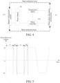
- the heating process includes a plurality of heating periods, each heating period includes two preset heating durations t1 and t2, and two preset switching durations t3 and t4, the preset direct-axis current id is in a positive direction and has a constant amplitude value within the first preset heating duration 11, the preset direct-axis current id is in a negative direction and has a constant amplitude value within the second preset heating duration t2, the preset direct-axis current id changes from the positive direction to the negative direction and has a changing amplitude value within the first preset switching duration t3, and the preset direct-axis current id changes from the negative direction to the positive direction and has a changing amplitude value within the second preset switching duration t4.
- the first preset heating duration t1 is equal to the second preset heating duration t2, the first preset switching duration t3 is equal to the second preset switching duration t4, and the preset heating duration is greater than the preset switching duration.
- the preset heating duration is far greater than the preset switching duration, and a minimum preset switching duration needs to ensure that the vehicle has no obvious jitter.
- a current three-phase current value and position and angle information of a motor rotor of the three-phase alternating current motor need to be obtained before the power battery is heated, and the current three-phase current value is converted into a direct-axis current and a quadrature-axis current according to the position and angle information of the motor rotor, so as to control the three-phase inverter according to the direct-axis current, the quadrature-axis current, the preset direct-axis current, and the preset quadrature-axis current to adjust the phase current of the three-phase alternating current motor in the heating process, thereby heating the power battery, and ensuring that a relatively small torque value is outputted at a motor shaft.
- parameters such as a three-phase current value and position and angle information of a motor rotor of the three-phase alternating current motor before the heating are obtained, to obtain a direct-axis current and a quadrature-axis current according to the obtained parameters, facilitating in controlling the three-phase inverter according to the direct-axis current, the quadrature-axis current, the preset direct-axis current, and the preset quadrature-axis current to adjust the phase current of the three-phase alternating current motor in the heating process, thereby adjusting the heating power.
- a specific process of obtaining the direct-axis current and the quadrature-axis current according to the position and angle information of the motor rotor and the current three-phase current value is: after the current three-phase current value and the position and angle information of the motor rotor of the three-phase alternating current motor are obtained before the power battery is heated, transforming the current three-phase current value from a natural coordinate system to a static coordinate system, and converting the current three-phase current value in the static coordinate system into a direct-axis current and a quadrature-axis current in a synchronous rotating coordinate system according to the position and angle information of the motor rotor.
- the current three-phase current value is transformed from a natural coordinate system to a static coordinate system, and the current three-phase alternating current value in the static coordinate system is converted into a direct-axis current and a quadrature-axis current in a synchronous rotating coordinate system according to the position and angle information of the motor rotor, so that the three-phase inverter may be controlled according to the obtained direct-axis current and quadrature-axis current to adjust the phase current of the three-phase alternating current motor based on the standard of the same coordinate system, thereby improving the accuracy of the adjustment process.
- the direct-axis current and the quadrature-axis current are respectively compared with the preset direct-axis current id and the preset quadrature-axis current iq, to adjust the direct-axis current and the quadrature-axis current according to the preset direct-axis current id and the preset quadrature-axis current iq, thereby controlling the three-phase inverter according to the preset direct-axis current id and the preset quadrature-axis current iq.
- a direct-axis voltage Ud and a quadrature-axis voltage Uq may be obtained according to data obtained by decoupling an adjustment result.
- coordinate transformation is performed on the direct-axis voltage Ud and the quadrature-axis voltage Uq to obtain a first voltage U ⁇ and a second voltage U ⁇ , so as to obtain a switching signal according to the first voltage U ⁇ and the second voltage U ⁇ , thereby controlling the three-phase inverter according to the switching signal to adjust the phase current of the three-phase alternating current motor.
- the obtained direct-axis current and quadrature-axis current are adjusted according to the preset direct-axis current and the preset quadrature-axis current, to obtain a corresponding adjustment result, and a series of changes are performed on the adjustment result, to obtain a switching signal of the three-phase inverter, that is, an on/off time of the power device in the three-phase inverter, so that the three-phase inverter is controlled according to the switching signal to adjust the phase current of the three-phase alternating current motor, thereby implementing closed-loop control of the three-phase alternating current motor, and adjusting the heating power, which improves the effectiveness in the heating process of the power battery, and reduces a loss in parts and components such as the motor.
- Step S15 Monitor temperatures of the three-phase inverter and the three-phase alternating current motor in the heating process of the power battery, and if a temperature of either of the three-phase inverter and the three-phase alternating current motor exceeds a temperature limit value, reduce the preset direct-axis current, or set the preset direct-axis current to zero.
- any device in the heating process of the power battery, any device may be damaged in a case of an excessively high temperature. Therefore, temperatures of the three-phase alternating current motor and the power device in the three-phase inverter need to be monitored in real time. If it is detected that a temperature of either of the three-phase inverter and the three-phase alternating current motor exceeds a temperature threshold, a current amplitude value of the preset direct-axis current id is reduced or the preset direct-axis current id is set to zero.
- the power battery heating method further includes: setting the preset quadrature-axis current to zero.
- temperatures of the three-phase inverter and the three-phase alternating current motor are monitored in real time, so that when a temperature of either of the three-phase inverter and the three-phase alternating current motor exceeds a temperature threshold, the preset direct-axis current id is reduced, or the preset direct-axis current id and the preset quadrature-axis current iq are set to zero, and values of phase currents flowing through three phase windings of the three-phase alternating current motor are also reduced or become zero.
- the heating power of the motor is reduced, and thus a temperature of a power unit in the three-phase inverter and temperatures of the three phase windings of the three-phase alternating current motor are reduced, so that all the parts and components of the vehicle are not damaged while ensuring the heating effect.
- Step S 16 Monitor a temperature of the power battery in the heating process of the power battery, and reduce the preset direct-axis current if the temperature of the power battery reaches a specified heating temperature.
- a temperature of the power battery when a temperature of the power battery reaches a specified heating temperature, it indicates that there is no need to heat the power battery. In this case, it needs to stop heating the power battery, that is, reduce the preset direct-axis current id, until the preset direct-axis current id is reduced to zero.
- a temperature of the power battery is monitored in real time in the heating process, and when the temperature of the power battery reaches a specified heating temperature, the preset direct-axis current id is reduced, to effectively avoid overheating of the power battery, and avoid a damage to the power battery, thereby prolonging the service life of the power battery.
- the power battery heating method further includes: obtaining required heating power of the power battery in real time in the heating process of the power battery, and adjusting a value of the preset direct-axis current according to the required heating power.
- the adjusting a value of the preset direct-axis current according to the required heating power refers to adjusting heating power according to a difference between a preset target heating temperature and a current temperature of the power battery, where a larger difference indicates larger heating power, and larger power indicates a larger amplitude value of the preset direct-axis current.
- relatively large power that is, a current battery temperature of the power battery is relatively low, for example, when a difference between the current temperature and a target temperature that needs to be reached during heating exceeds 10°C, heating is performed by using relatively large power. In this case, an amplitude value of the preset direct-axis current id is increased.
- a current battery temperature of the power battery is relatively large, for example, when a difference between the current temperature and a target temperature that needs to be reached during heating is less than 10°C, heating is performed by using relatively low power. In this case, an amplitude value of the preset direct-axis current id is reduced.
- required heating power of the power battery is obtained in real time in the heating process, and the preset direct-axis current id and the preset quadrature-axis current iq are adjusted according to the required heating power, to effectively avoid overheating of the power battery, and avoid a damage to the power battery, thereby prolonging the service life of the power battery.
- the power battery heating method further includes: setting the preset direct-axis current to zero in a case of determining that any fault status in the fault status of the power battery, the fault status of the three-phase alternating current motor, the fault status of the motor controller, and the fault status of the heat conduction loop indicates that there is a fault.
- the fault status of the three-phase alternating current motor, the fault status of the motor controller, and the fault status of the heat conduction loop indicates that there is a fault, it indicates that the power battery cannot be heated, and heating of the power battery should be stopped, that is, the preset direct-axis current and the preset quadrature-axis current are set to zero.
- the power battery heating method further includes: setting the preset quadrature-axis current to zero.
- the fault status of the three-phase alternating current motor, the fault status of the motor controller, and the fault status of the heat conduction loop indicates that there is a fault
- heating of the power battery is stopped, to effectively avoid a damage to the power battery, thereby prolonging the service life of the power battery.
- An embodiment of this application provides a power battery heating apparatus, configured to heat a power battery of a vehicle.
- the power battery heating apparatus includes:
- the heating energy source 10 is implemented by using an external power supply device such as a charging pile.
- the heating energy may be the power battery itself. That is, the heating energy provided by the heating energy source 10 may be outputted by the power battery, or may be outputted by a direct current charger, or may be outputted by an alternating current charger after rectifying, which is not specifically limited herein.
- the three-phase inverter 11 has four working modes, which is determined by the control module 13.
- the three-phase inverter 11 When configured to drive the vehicle, the three-phase inverter 11 works in an inverter mode; when configured to boost for charging, the three-phase inverter 11 works in a boost mode; when configured to heat a battery, the three-phase inverter 11 works in a heating mode; when needing to supply power to the outside, the three-phase inverter 11 works in a changing voltage mode. Only a case in which the three-phase inverter 11 works in the heating mode is described in detail in the embodiments of this application.
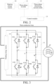
- the three-phase inverter 11 includes six power switching units.
- the power switch may be a transistor, an IGBT, or a MOS transistor, or other device types. Two power switching units form a phase leg, and a total of three phase legs are formed.
- a connecting point between two power switching units on each phase leg is connected to a phase coil in the three-phase alternating current motor 12.
- the three-phase alternating current motor 12 includes three phase coils, and the three phase coils are connected to one midpoint.
- the three-phase alternating current motor 12 may be a permanent magnet synchronizing motor, an asynchronous motor, or the like.
- a type of the three-phase alternating current motor is not specifically limited in this application.
- the three-phase inverter 11 includes a first power switching unit, a second power switching unit, a third power switching unit, a fourth power switching unit, a fifth power switching unit, and a sixth power switching unit.
- a control terminal of each power switching unit is connected to the control module 13 (not shown in the figure), first terminals of the first power switching unit, the third power switching unit, and the fifth power switching unit are connected together, and second terminals of the second power switching unit, the fourth power switching unit, and the sixth power switching unit are connected together.
- a first phase coil of the three-phase alternating current motor 12 is connected to a second terminal of the first power switching unit and a first terminal of the second power switching unit, a second phase coil of the three-phase alternating current motor 12 is connected to a second terminal of the third power switching unit and a first terminal of the fourth power switching unit, and a third phase coil of the three-phase alternating current motor 12 is connected to a second terminal of the fifth power switching unit and a first terminal of the sixth power switching unit.
- first power switching unit and the second power switching unit in the three-phase inverter 11 form a first phase leg (U-phase leg)
- third power switching unit and the fourth power switching unit form a second phase leg (V-phase leg)
- fifth power switching unit and the sixth power switching unit form a third phase leg (W-phase leg).
- the first power switching unit includes a first upper leg VT1 and a first upper diode VD1
- the second power switching unit includes a second lower leg VT2 and a second lower diode VD2
- the third power switching unit includes a third upper leg VT3 and a third upper diode VD3
- the fourth power switching unit includes a fourth lower leg VT4 and a fourth lower diode VD4
- the fifth power switching unit includes a fifth upper leg VT5 and a fifth upper diode VD5
- the sixth power switching unit includes a sixth lower leg VT6 and a sixth lower diode VD6.
- the three-phase alternating current motor 12 may be a permanent magnet synchronizing motor or an asynchronous motor, and the three phase coils of the motor are respectively connected to upper legs and lower legs of the U, V, and W phases in the three-phase inverter.
- control module 13 may include a vehicle control unit, a control circuit of a motor controller, and a battery management system (BMS) circuit, which are connected by using a CAN bus.
- BMS battery management system
- Different modules in the control module 13 control, according to obtained information, switching-on and switching-off of switching units in the three-phase inverter 11, to implement conduction of different current loops.
- the heating energy source 10, the three-phase inverter 11, and the three-phase alternating current motor 12 are provided with an interworking coolant tube. A coolant flows through the coolant tube, and a temperature of the power battery may be adjusted by adjusting a temperature of the coolant in the coolant tube.
- the control module 13 includes a battery management system 131 and a motor controller 132.
- the battery management system 131 is connected to the power battery 20, and the motor controller 132 is connected to the power battery and the three-phase alternating current motor 12.
- the battery management system 131 obtains a temperature of the power battery, and compares the temperature of the power battery with a preset temperature value, to determine whether the power battery is in a low temperature state. When it is detected that the temperature of the power battery is lower than the preset temperature value, the temperature of the power battery may be raised by raising a temperature of a coolant flowing through the power battery.
- the motor controller 132 may control the three-phase inverter 11 and the three-phase alternating current motor 12 to heat the coolant flowing through the power battery, and stop heating until it is detected that the temperature of the power battery reaches the preset temperature value.
- the motor controller 132 obtains a current working status of the motor of the vehicle, a fault status of the power battery, a fault status of the three-phase alternating current motor 12, a fault status of the motor controller 132, and a fault status of a heat conduction loop, and determines, according to the fault statuses and the current working status of the motor, whether a heating condition of the power battery is met.
- the heating condition of the power battery meets the preset condition, in a case of determining that the current working status of the motor is a non-driving state, and determining that the fault status of the power battery, the fault status of the three-phase alternating current motor, the fault status of the motor controller, and the fault status of the heat conduction loop all indicate that no fault exists; it is identified that the heating condition of the power battery does not meet the preset condition, in a case of determining that the current working status of the motor is a driving state, or determining that any fault status in the fault status of the power battery, the fault status of the three-phase alternating current motor, the fault status of the motor controller, and the fault status of the heat conduction loop indicates that there is a fault.
- the motor controller 132 in a case of determining that any fault status in the fault status of the power battery, the fault status of the three-phase alternating current motor, the fault status of the motor controller, and the fault status of the heat conduction loop indicates that there is a fault, the motor controller 132 is further configured to set the preset direct-axis current id to zero.
- the motor controller 132 is further configured to set the preset quadrature-axis current iq to zero.
- the motor controller 132 may first obtain gear position information and motor speed information, and obtain the current working status of the motor according to the gear position information and the motor speed information.
- the motor controller 132 determines that a current gear position is a P gear position, and a motor speed is zero, it indicates that the current working status of the motor is a non-driving state; and when the motor controller 132 determines that the current gear position is not the P gear position, or the motor speed is not zero, it indicates that the current working status of the motor is a driving state. It should be noted that in the embodiments of the present invention, there is no sequence between two determining conditions of the working status of the motor and the temperature of the power battery.
- the three-phase inverter 11 when it is detected, in a parking state, that gear position information, motor speed information, and temperature information of the power battery meet a preset condition, the three-phase inverter 11 is controlled to cause the three-phase alternating current motor 12 to heat a coolant flowing through the power battery according to heating energy, to heat the power battery when the vehicle is in the parking state, facilitating that the vehicle may be normally started in a low temperature, and avoiding that the performance of the vehicle is affected because the power battery is heated when the vehicle is in a normal traveling state.
- the motor controller 132 controls the three-phase inverter 11 and the three-phase alternating current motor 12 to heat the coolant flowing through the power battery
- the motor controller 132 mainly controls an on/off time and a switching frequency of each power unit in the three-phase inverter 11, to cause the three-phase alternating current motor 12 to generate heat according to heating energy provided by the heating energy source 10 (in this embodiment, for example, the heating energy source is the power battery), to heat a coolant flowing through the power battery.
- the motor controller 132 controls, according to the preset direct-axis current id and the preset quadrature-axis current iq, the three-phase inverter 11 to adjust a phase current of the three-phase alternating current motor 12 in the heating process.
- the power battery is connected to and in communication with the heat conduction loop of the three-phase alternating current motor 12, and a cooling medium flows through a vehicle-used power battery (the power battery) and a vehicle-used power motor (the three-phase alternating current motor 12) by using a pump (not shown in the figure) and a communication valve (not shown in the figure).
- the preset direct-axis current id is a direct-axis current that is preset according to heating power, and the preset direct-axis current id may control the heating power, and has a periodically changing direction in the process of controlling the heating power. Specifically, as shown in FIG.
- the heating process includes a plurality of heating periods, each heating period includes two preset heating durations t1 and t2, and two preset switching durations t3 and t4, the preset direct-axis current id is in a positive direction and has a constant amplitude value within the first preset heating duration 11, the preset direct-axis current id is in a negative direction and has a constant amplitude value within the second preset heating duration t2, the preset direct-axis current id changes from the positive direction to the negative direction and has a linearly changing amplitude value within the first preset switching duration t3, and the preset direct-axis current id changes from the negative direction to the positive direction and has a linearly changing amplitude value within the second preset switching duration t4.
- the first preset heating duration t1 is equal to the second preset heating duration t2, the first preset switching duration t3 is equal to the second preset switching duration t4, and the preset heating duration is greater than the preset switching duration.
- the preset heating duration is far greater than the preset switching duration, so that a direction of the preset direct-axis current id changes quickly during changing, to avoid an excessively large change in an amplitude value of the preset direct-axis current id, and a minimum preset switching duration needs to ensure that the vehicle has no obvious jitter.
- the preset heating duration is preset according to power required for heating a battery
- the preset switching duration is preset according to a case that it is ensured that the vehicle has no obvious jitter in the heating process of the battery, both of which are not specifically limited herein.
- the motor controller 132 controls the preset direct-axis current to have a constant current amplitude value and to alternately change between the positive direction and the negative direction within a preset heating duration, thereby making quantities of times of switching-on and switching-off of an upper leg and a lower leg of power switching devices of the same phase in the three-phase inverter 11 equal, and service life of devices balanced.
- the preset heating duration is far greater than the preset switching duration, which can effectively reduce a switching time during changing of a current direction, and effectively avoid a jitter of the vehicle while ensuring a heating effect.
- the preset quadrature-axis current iq is a quadrature-axis current with a constant amplitude value, and the amplitude value is obtained through a large amount of experiments, so that electromagnetic torque with a relatively small torque value may be outputted at a motor shaft.
- the electromagnetic torque cannot cause the vehicle to move, and also cannot cause a damage to parts and components of a transmission mechanism of the vehicle.
- the electromagnetic torque only provides relatively small output torque to complete gap engagement of gears of the transmission mechanism of the vehicle or generate a pre-tightening force.
- the three-phase inverter 11 and the three-phase alternating current motor 12 are controlled to heat the coolant flowing through the power battery, and the preset direct-axis current is controlled according to required heating power in the heating process, so that the preset direct-axis current changes periodically in a process of adjusting the phase current of the three-phase alternating current motor, thereby making quantities of times of switching-on and switching-off of an upper leg and a lower leg of power switching devices of the same phase equal, and service life of devices balanced.
- the control module 13 when the control module 13 controls the three-phase inverter 11 according to the preset direct-axis current id and the preset quadrature-axis current iq to adjust the phase current of the three-phase alternating current motor 12, the control module 13 needs to obtain a current three-phase current value and position and angle information of a motor rotor of the three-phase alternating current motor 12 before the power battery is heated, and convert the current three-phase current value into a direct-axis current and a quadrature-axis current according to the position and angle information of the motor rotor, so as to control the three-phase inverter 11 according to the direct-axis current, the quadrature-axis current, the preset direct-axis current, and the preset quadrature-axis current to adjust the phase current of the three-phase alternating current motor 12 in the heating process.
- parameters such as a three-phase current value and position and angle information of a motor rotor of the three-phase alternating current motor before the heating are obtained, to obtain a direct-axis current and a quadrature-axis current according to the obtained parameters, facilitating in controlling the three-phase inverter according to the direct-axis current, the quadrature-axis current, the preset direct-axis current, and the preset quadrature-axis current to adjust the phase current of the three-phase alternating current motor in the heating process, making an amount of heat generated by windings of the three-phase alternating current motor constant.
- the control module 13 further includes a feedforward decoupling unit 133, a coordinate transformation unit 134, and a switching signal obtaining unit 135.
- the feedforward decoupling unit 133 is connected to the coordinate transformation unit 134
- the coordinate transformation unit 134 is connected to the switching signal obtaining unit 135 and the three-phase alternating current motor 12
- the switching signal obtaining unit 135 is connected to the motor controller 132
- the motor controller 132 is connected to the three-phase alternating current motor 12.
- the control module 13 respectively compares the direct-axis current and the quadrature-axis current with the preset direct-axis current id and the preset quadrature-axis current iq, to adjust the direct-axis current and the quadrature-axis current according to the preset direct-axis current id and the preset quadrature-axis current iq, thereby controlling the three-phase inverter according to the preset direct-axis current id and the preset quadrature-axis current iq.
- the feedforward decoupling unit 133 decouples the comparison result to obtain a direct-axis voltage Ud and a quadrature-axis voltage Uq.
- the coordinate transformation unit 134 performs coordinate transformation on the direct-axis voltage Ud and the quadrature-axis voltage Uq to obtain a first voltage U ⁇ and a second voltage U ⁇ .
- the switching signal obtaining unit 135 obtains a switching signal according to the first voltage U ⁇ and the second voltage U ⁇ .
- the motor controller 132 controls the three-phase inverter 11 according to the switching signal to adjust the phase current of the three-phase alternating current motor 12.
- the obtained direct-axis current and quadrature-axis current are adjusted according to the preset direct-axis current and the preset quadrature-axis current, to obtain a corresponding adjustment result, and a series of changes are performed on the adjustment result, to obtain a switching signal of the three-phase inverter, so that the motor controller controls the three-phase inverter according to the switching signal to adjust the phase current of the three-phase alternating current motor, thereby implementing closed-loop controlling of the three-phase alternating current motor, and adjusting the heating power, which improves the effectiveness in the heating process of the power battery, and reduces a loss in parts and components such as the motor.
- a specific process in which the control module 13 obtains the direct-axis current and the quadrature-axis current according to the position and angle information of the motor rotor and the current three-phase current value is: before the power battery is heated, obtaining ,by the control module 13, the current three-phase current value and the position and angle information of the motor rotor of the three-phase alternating current motor, then, transforming, by the coordinate transformation unit 134, the current three-phase current value from a natural coordinate system to a static coordinate system, and converting the current three-phase alternating current value in the static coordinate system into a direct-axis current and a quadrature-axis current in a synchronous rotating coordinate system according to the position and angle information of the motor rotor (as shown in FIG. 7 ).
- the current three-phase current value is transformed from a natural coordinate system to a static coordinate system, and the current three-phase alternating current value in the static coordinate system is converted into a direct-axis current and a quadrature-axis current in a synchronous rotating coordinate system according to the position and angle information of the motor rotor, so that the control module controls the three-phase inverter according to the obtained direct-axis current and quadrature-axis current to adjust the phase current of the three-phase alternating current motor based on the standard of the same coordinate system, thereby improving the accuracy of the adjustment process.
- the power battery heating apparatus is further provided with a temperature monitoring unit.
- the temperature monitoring unit is connected to the motor controller 132 in the control module and the three-phase alternating current motor 12.
- the temperature monitoring unit is configured to monitor temperatures of the three-phase inverter 11 and the three-phase alternating current motor 12 in real time in the heating process of the power battery, and feed back a result of monitoring to the control module 13. If a temperature of either of the three-phase inverter 11 and the three-phase alternating current motor 12 exceeds a temperature limit value, the control module 13 reduces the preset direct-axis current id, or sets the preset direct-axis current id to zero.
- control module 13 is further configured to set the preset quadrature-axis current iq to zero.
- the temperature monitoring unit is implemented by using a temperature sensor.
- the temperature sensor may be implemented by using a negative temperature coefficient thermistor, or may be implemented by using a positive temperature coefficient thermistor, which is not specifically limited herein.
- any device in the heating process of the power battery, any device may be damaged in a case of an excessively high temperature. Therefore, temperatures of the three-phase alternating current motor and the power device in the three-phase inverter need to be monitored in real time. If it is detected that a temperature of either of the three-phase inverter and the three-phase alternating current motor exceeds a temperature threshold, a current amplitude value of the preset direct-axis current id is reduced or the preset direct-axis current id and the preset quadrature-axis current iq are set to zero.
- temperatures of the three-phase inverter and the three-phase alternating current motor are monitored in real time, so that when a temperature of either of the three-phase inverter and the three-phase alternating current motor exceeds a temperature threshold, the preset direct-axis current id is reduced, or the preset direct-axis current id and the preset quadrature-axis current iq are set to zero, and values of phase currents flowing through three phase windings of the three-phase alternating current motor are also reduced or become zero.
- the heating power of the motor is reduced, and thus a temperature of a power unit in the three-phase inverter and temperatures of the three phase windings of the three-phase alternating current motor are reduced, so that all the parts and components of the vehicle are not damaged while ensuring the heating effect.
- control module is further configured to monitor a temperature of the power battery in real time in the heating process of the power battery, and stop heating the power battery if the temperature of the power battery reaches a specified heating temperature.
- a temperature of the power battery when a temperature of the power battery reaches a specified heating temperature, it indicates that there is no need to heat the power battery. In this case, it needs to stop heating the power battery, that is, reduce a direct-axis current and a quadrature-axis current.
- a temperature of the power battery is monitored in real time in the heating process, and when the temperature of the power battery reaches a specified heating temperature, the preset direct-axis current and the preset quadrature-axis current are reduced, to effectively avoid overheating of the power battery, and avoid a damage to the power battery, thereby prolonging the service life of the power battery.
- control module 13 is further configured to obtain required heating power of the power battery in real time in the heating process of the power battery, and adjust a value of the preset direct-axis current id according to the required heating power.
- the heating process goes on, the temperature of the power battery constantly rises, and the rising of the temperature causes heating power required by the power battery to change constantly. Therefore, in the heating process of the power battery, required heating power of the power battery needs to be obtained in real time, and a value of the preset direct-axis current id needs to be adjusted according to the required heating power.
- required heating power of the power battery is obtained in real time in the heating process, and the preset direct-axis current id is adjusted according to the required heating power, to effectively avoid overheating of the power battery, and avoid a damage to the power battery, thereby prolonging the service life of the power battery.
- a standby state at which the three-phase alternating current motor 12 heats the power battery is entered.
- the control module 13 needs to determine a heating condition, that is, determines whether the temperature of the power battery is excessively low, whether a motor speed is zero, and whether a gear position is a P gear position. If all determination results of the heating condition are true, a process of generating heat by using the three-phase alternating current motor 12 to heat the power battery may be performed.
- a sensor During heating, a sensor first performs signal sampling on each current variable of the motor, and transmits a sampling result to the control module 13.
- Sampled variables are mainly a three-phase current value that currently flows through windings of the three-phase alternating current motor 12 and position and angle information of a motor rotor (a current rotor position of the motor).
- the coordinate transformation unit 134 converts variables in a natural coordinate system ABC into variables in a static coordinate system ⁇ - ⁇ through clark transformation, and then converts the variables in the static coordinate system ⁇ - ⁇ into variables in a synchronous rotating coordinate system d-q through park transformation.
- a condition that an amplitude value is constant is followed in the entire coordinate transformation, and a transformation coefficient 2/3 is added in front of a transformation matrix.
- the coordinate transformation unit 134 converts the variables in the natural coordinate system ABC into the variables in the static coordinate system ⁇ - ⁇
- the coordinate transformation unit 134 converts the variables in the static coordinate system ⁇ - ⁇ into the variables in the synchronous rotating coordinate system d-q
- ⁇ in the formula is an angle (the position and angle information of the motor rotor) between a direct rotor axis of the three-phase alternating current motor 12 and an A-phase winding of the three-phase alternating current motor 12.
- a three-phase current in the natural coordinate system ABC may be converted into a quadrature-axis current and a direct-axis current through the transformation matrix T 3 s /2 r .
- the direct-axis current is an exciting current
- the quadrature-axis current is a torque current, that is, only the quadrature-axis current is related to torque outputted at a motor shaft. Therefore, in the process of heating the power battery by using the three-phase alternating current motor 12, output of torque at the motor shaft may be controlled by controlling the quadrature-axis current.
- a control algorithm cannot control the quadrature-axis current to be always zero, and thus a quadrature-axis current value fluctuates around zero, making the entire vehicle jitter. In different working conditions, jitter strength is also different. If there is an occupant in the vehicle at this time, a bad driving feeling is generated.
- an amplitude value of the preset direct-axis current id is controlled in real time to be a value corresponding to required heating power, and a direction of the current is periodically changed.
- an amplitude value of the preset quadrature-axis current iq is controlled to be an appropriate constant value. The value cannot make the occupant feel that the vehicle is moving or jittering, nor cause a potential damage to the transmission mechanism of the vehicle, but only torque with a relatively small amplitude value is outputted at a motor shaft, which falls within an acceptable range of the mechanical strength of the transmission mechanism. In this way, an effect similar to a pre-tightening force is to be generated, eliminating an engagement gap between transmission mechanisms.
- T e indicates torque outputted at the motor shaft
- p indicates a quantity of pole pairs
- ⁇ f indicates a permanent magnet flux linkage of the motor
- L d indicates a direct-axis inductance
- L q indicates a quadrature-axis inductance
- i d indicates a direct-axis current
- i q indicates a quadrature-axis current.
- the power battery heating apparatus provided in the embodiments of this application provides a preset direct-axis current having a periodically changing direction.
- the current is in a positive direction within a first half period, and the current is in a negative direction within a second half period (it should be noted that switching times of the direction of the current within the first half period and the second half period are negligible herein), thereby making quantities of times of switching-on and switching-off of an upper leg and a lower leg of power switching devices of the same phase in the three-phase inverter 11 equal, and service life of devices balanced.
- the direct-axis current and the quadrature-axis current may be respectively compared with the preset direct-axis current id and the preset quadrature-axis current iq, and a comparison result is fed back to the feedforward decoupling unit 133.
- the feedforward decoupling unit 133 performs complete decoupling on the variables in a feedforward compensation manner.
- U ⁇ and U ⁇ are transmitted to the switching signal obtaining unit 135, and the switching signal obtaining unit 134 obtains, by using a space vector pulse width modulation (SVPWM) algorithm, six switching signals for controlling the three-phase inverter 11.
- the motor controller 132 controls, by using the six switching signals, power switching devices in the three-phase inverter 11 to perform on/off actions, so as to control a three-phase current value flowing through the three-phase alternating current motor.
- SVPWM space vector pulse width modulation
- a temperature sensor constantly monitors temperatures of windings of the three-phase alternating current motor and power switches of the three-phase inverter. If any of them exceeds a temperature limit value, or a current temperature of the power battery gradually approaches a pre-determined target heating temperature, or the current temperature of the power battery has reached or exceeds the pre-determined target heating temperature, the motor controller reduces the given id value or sets id or iq to zero. Therefore, values of phase currents flowing through three phase windings of the three-phase alternating current motor are also reduced or become zero, and heating power of the motor is also reduced, so that temperatures of the power switches of the three-phase inverter and temperatures of the windings of the three-phase alternating current motor are also reduced.
- the battery management system transmits a heating stop instruction when monitoring that the temperature of the battery has reached the pre-determined heating temperature. In this case, the process in which the three-phase alternating current motor generates heat to heat the vehicle-used power battery ends.
- the vehicle 1000 includes the power battery heating apparatus 100 in the foregoing embodiment, and further includes a power battery, a coolant tank, a pump, and a water pipeline, the pump inputs a coolant in the coolant tank into the water pipeline according to a control signal, and the water pipeline passes through the power battery and the power battery heating apparatus 100.
- a three-phase inverter is controlled to cause a three-phase alternating current motor to generate heat according to heating energy, to heat a coolant flowing through the power battery, a preset quadrature-axis current that causes a torque value outputted by the motor to be an appropriate value is obtained, and a corresponding preset direct-axis current is obtained according to heating power of the power battery, so as to control, according to the preset direct-axis current and the preset quadrature-axis current, the three-phase inverter to adjust a phase current of the three-phase alternating current motor in the heating process, where a direction of the preset direct-axis current changes periodically in the heating process, thereby making quantities of times of switching-on and switching-off of an upper leg and a lower leg of power switching devices of the same phase equal, and service life of devices balanced.
Landscapes
- Engineering & Computer Science (AREA)
- Chemical & Material Sciences (AREA)
- Manufacturing & Machinery (AREA)
- Chemical Kinetics & Catalysis (AREA)
- Electrochemistry (AREA)
- General Chemical & Material Sciences (AREA)
- Power Engineering (AREA)
- Mechanical Engineering (AREA)
- Transportation (AREA)
- Automation & Control Theory (AREA)
- Life Sciences & Earth Sciences (AREA)
- Sustainable Development (AREA)
- Sustainable Energy (AREA)
- Physics & Mathematics (AREA)
- Thermal Sciences (AREA)
- Combustion & Propulsion (AREA)
- Electric Propulsion And Braking For Vehicles (AREA)
- Inverter Devices (AREA)
- Control Of Electric Motors In General (AREA)
- Control Of Ac Motors In General (AREA)
Claims (11)
- Verfahren zum Heizen einer Leistungsbatterie (20), das zum Heizen einer Leistungsbatterie (20) eines Fahrzeugs konfiguriert ist, wobei das Verfahren zum Heizen der Leistungsbatterie umfasst:Ermitteln eines aktuellen Temperaturwerts der Leistungsbatterie (20) und Feststellen, dass der aktuelle Temperaturwert der Leistungsbatterie (20) niedriger ist als ein voreingestellter Temperaturwert (S11);Erhalten einer Heizleistung der Leistungsbatterie (20) (S12);Erhalten eines voreingestellten Quadraturachsenstroms und Erhalten eines entsprechenden voreingestellten Gleichachsenstroms gemäß der Heizleistung der Leistungsbatterie (20), wobei ein Wert des erhaltenen voreingestellten Quadraturachsenstroms ein Quadraturachsenstromwert ist, der bewirkt, dass ein von einem Dreiphasen-Wechselstrommotor (12) ausgegebener Drehmomentwert in einen Zielbereich fällt, wobei Null nicht in dem Zielbereich enthalten ist (S13);Steuern eines Ein/Aus-Status einer Leistungsvorrichtung in einem Dreiphasen-Wechselrichter (11), so dass der Dreiphasen-Wechselstrommotor (12) entsprechend der von einer Heizenergiequelle gelieferten Heizenergie Wärme erzeugt, um ein durch die Leistungsbatterie (20) fließendes Kühlmittel zu erhitzen, und Steuern, gemäß dem voreingestellten Gleichachsenstrom und dem voreingestellten Quadraturachsenstrom den Dreiphasen-Wechselrichter (11), um einen Phasenstrom des Dreiphasen-Wechselstrommotors (12) in dem Heizprozess einzustellen,dadurch gekennzeichnet, dass sich eine Richtung des voreingestellten Gleichachsenstroms in dem Heizprozess periodisch ändert (S14);wobei die Heizenergiequelle eine externe Ladevorrichtung ist; undwobei der Heizprozess eine Vielzahl von Heizperioden umfasst, jede Heizperiode zwei voreingestellte Heizdauern und zwei voreingestellte Schaltdauern umfasst, der voreingestellte Gleichachsenstrom in einer positiven Richtung ist und einen konstanten Amplitudenwert innerhalb der ersten voreingestellten Heizdauer hat, der voreingestellte Gleichachsenstrom in einer negativen Richtung ist und einen konstanten Amplitudenwert innerhalb der zweiten voreingestellten Heizdauer hat, der voreingestellte Gleichachsenstrom von der positiven Richtung in die negative Richtung wechselt und innerhalb der ersten voreingestellten Schaltdauer einen sich ständig ändernden Amplitudenwert aufweist, und der voreingestellte Gleichachsenstrom von der negativen Richtung in die positive Richtung wechselt und innerhalb der zweiten voreingestellten Schaltdauer einen sich ständig ändernden Amplitudenwert aufweist; und die voreingestellte Heizdauer größer ist als die voreingestellte Schaltdauer.
- Verfahren zum Heizen einer Leistungsbatterie nach Anspruch 1, wobei das Verfahren vor dem Erhalten der Heizleistung der Leistungsbatterie (20) ferner umfasst: Bestimmen, ob ein Heizzustand der Leistungsbatterie (20) eine voreingestellte Bedingung erfüllt; und das Bestimmen, ob ein Heizzustand der Leistungsbatterie (20) eine voreingestellte Bedingung erfüllt, umfasst:Identifizieren, dass der Heizzustand der Leistungsbatterie (20) die voreingestellte Bedingung erfüllt, wenn festgestellt wird, dass ein aktueller Arbeitszustand des Motors ein Nicht-Antriebszustand ist, und Feststellen, dass ein Fehlerzustand bzw- -status der Leistungsbatterie (20), ein Fehlerzustand des Drehstrommotors (12), ein Fehlerzustand einer Motorsteuerung und ein Fehlerzustand einer Wärmeleitschleife alle anzeigen, dass kein Fehler vorliegt; undErkennen, dass der Heizzustand der Leistungsbatterie (20) nicht der voreingestellten Bedingung entspricht, wenn festgestellt wird, dass der aktuelle Arbeitszustand des Motors ein Antriebszustand ist, oder wenn festgestellt wird, dass irgendein Fehlerstatus von dem Fehlerstatus der Leistungsbatterie (20), dem Fehlerstatus des Drehstrommotors (12), dem Fehlerstatus der Motorsteuerung und dem Fehlerstatus der Wärmeleitschleife auf einen Fehler hinweist.
- Verfahren zum Heizen einer Leistungsbatterie nach Anspruch 2, das außerdem Folgendes umfasst:
Erhalten von Informationen über die Getriebeposition und die Motordrehzahl, und das Erhalten des aktuellen Arbeitsstatus des Motors gemäß den Informationen über die Getriebeposition und die Motordrehzahl, oder weiterhin umfassend:
Setzen des voreingestellten Gleichachsenstroms auf Null, wenn festgestellt wird, dass irgendein Fehlerstatus von dem Fehlerstatus der Leistungsbatterie (20), dem Fehlerstatus des Drehstrommotors (12), dem Fehlerstatus des Motorreglers und dem Fehlerstatus der Wärmeleitschleife auf einen Fehler hinweist, wobei das Heizverfahren für die Leistungsbatterie (20) in dem Fall, in dem festgestellt wird, dass irgendein Fehlerstatus von dem Fehlerstatus der Leistungsbatterie (20), dem Fehlerstatus des Drehstrommotors (12), dem Fehlerstatus des Motorreglers und dem Fehlerstatus der Wärmeleitschleife anzeigt, dass ein Fehler vorliegt, vorzugsweise umfasst:
Setzen des voreingestellten Quadraturachsenstroms auf Null. - Verfahren zum Heizen einer Leistungsbatterie nach einem der Ansprüche 1 bis 3, das außerdem Folgendes umfasst:
Überwachen der Temperaturen des dreiphasigen Wechselrichters (11) und des dreiphasigen Wechselstrommotors (12) beim Aufheizen der Energiebatterie (20), und wenn eine Temperatur des dreiphasigen Wechselrichters (11) oder des dreiphasigen Wechselstrommotors (12) einen Temperaturgrenzwert überschreitet, Reduzieren des voreingestellten Gleichachsenstroms oder Setzen des voreingestellten Gleichachsenstroms auf Null (S15). - Verfahren zum Heizen einer Leistungsbatterie nach Anspruch 4, wobei das Verfahren zum Heizen der Leistungsbatterie (20) weiterhin umfasst, wenn die Temperatur des Drehstromwechselrichters (11) oder des Drehstrommotors (12) den Temperaturgrenzwert überschreitet:
Setzen des voreingestellten Quadraturachsenstroms auf Null. - Verfahren zum Heizen einer Leistungsbatterie nach einem der Ansprüche 1 bis 3, das außerdem Folgendes umfasst:
Überwachen einer Temperatur der Leistungsbatterie (20) während des Heizvorgangs der Leistungsbatterie (20) und Reduzieren des voreingestellten Gleichachsenstroms, wenn die Temperatur der Leistungsbatterie (20) eine bestimmte Heiztemperatur (S16) erreicht, und/oder weiter umfassend:
Erhalten eines aktuellen Drehstromwerts und von Positions- und Winkelinformationen eines Motorrotors des Drehstrommotors (12), bevor die Leistungsbatterie (20) geheizt wird, und Umwandeln des aktuellen Drehstromwerts in einen Gleichachsenstrom und einen Quadraturachsenstrom gemäß den Positions- und Winkelinformationen des Motorrotors. - Heizvorrichtung für eine Leistungsbatterie, die so konfiguriert ist, dass sie eine Leistungsbatterie (20) eines Fahrzeugs erwärmt, wobei die Heizvorrichtung für die Leistungsbatterie umfasst:einen dreiphasigen Wechselrichter (11), der mit einer positiven Elektrode und einer negativen Elektrode einer Heizenergiequelle verbunden ist, die zur Bereitstellung von Heizenergie konfiguriert ist;einen Dreiphasen-Wechselstrommotor (12), wobei drei Phasenspulen des Dreiphasen-Wechselstrommotors (12) mit drei Phasenbeinen des Dreiphasen-Wechselrichters (11) verbunden sind; undein Steuermodul (13), wobei das Steuermodul (13) mit dem dreiphasigen Wechselrichter (11) bzw. dem dreiphasigen Wechselstrommotor (12) verbunden ist und so konfiguriert ist, dass es einen aktuellen Temperaturwert der Leistungsbatterie (20) ermittelt und feststellt, dass der aktuelle Temperaturwert der Leistungsbatterie (20) niedriger als ein voreingestellter Temperaturwert ist, und eine Heizleistung der Leistungsbatterie (20) ermittelt; das Steuermodul (13) ferner so konfiguriert ist, dass es einen voreingestellten Quadraturachsenstrom erhält und einen entsprechenden voreingestellten Gleichachsenstrom entsprechend der Heizleistung der Leistungsbatterie (20) erhält, wobei ein Wert des erhaltenen voreingestellten Quadraturachsenstroms ein Quadraturachsenstromwert ist, der bewirkt, dass ein von dem Dreiphasen-Wechselstrommotor (12) ausgegebener Drehmomentwert in einen Zielbereich fällt, wobei Null nicht in dem Zielbereich enthalten ist; unddas Steuermodul (13) ferner so konfiguriert ist, dass es einen Ein/Aus-Status einer Leistungsvorrichtung in dem Dreiphasen-Wechselrichter (11) steuert, so dass der Drehstrommotor (12) entsprechend der von der Heizenergiequelle bereitgestellten Heizenergie Wärme erzeugt, um ein durch die Leistungsbatterie (20) fließendes Kühlmittel zu erwärmen, und steuert, entsprechend dem voreingestellten Gleichachsenstrom und dem voreingestellten Quadraturstrom den Dreiphasenwechselrichter (11), um einen Phasenstrom des Drehstrommotors (12) im Heizprozess einzustellen, dadurch gekennzeichnet, dass sich eine Richtung des voreingestellten Gleichachsenstroms im Heizprozess periodisch ändert,wobei die Heizenergiequelle eine externe Ladevorrichtung ist; undwobei der Heizprozess eine Vielzahl von Heizperioden umfasst, jede Heizperiode zwei voreingestellte Heizdauern und zwei voreingestellte Schaltdauern umfasst, der voreingestellte Gleichachsenstrom in einer positiven Richtung ist und einen konstanten Amplitudenwert innerhalb der ersten voreingestellten Heizdauer hat, der voreingestellte Gleichachsenstrom in einer negativen Richtung ist und einen konstanten Amplitudenwert innerhalb der zweiten voreingestellten Heizdauer hat, der voreingestellte Gleichachsenstrom von der positiven Richtung in die negative Richtung wechselt und innerhalb der ersten voreingestellten Schaltdauer einen sich ständig ändernden Amplitudenwert aufweist, und der voreingestellte Gleichachsenstrom von der negativen Richtung in die positive Richtung wechselt und innerhalb der zweiten voreingestellten Schaltdauer einen sich ständig ändernden Amplitudenwert aufweist; und die voreingestellte Heizdauer größer ist als die voreingestellte Schaltdauer.
- Heizvorrichtung für eine Leistungsbatterie nach Anspruch 7, wobei das Steuermodul (13) ferner so konfiguriert ist, dass es feststellt, ob ein Heizzustand der Batterie (20) eine vorgegebene Bedingung erfüllt;feststellt, dass der Heizzustand der Leistungsbatterie (20) die voreingestellte Bedingung erfüllt, wenn festgestellt wird, dass ein aktueller Arbeitszustand des Motors ein Nicht-Antriebszustand ist, und feststellt, dass ein Fehlerzustand bzw. -status der Leistungsbatterie (20), ein Fehlerzustand des Drehstrommotors (12), ein Fehlerzustand einer Motorsteuerung und ein Fehlerzustand einer Wärmeleitschleife alle anzeigen, dass kein Fehler vorliegt; undfeststellt, dass der Heizzustand der Leistungsbatterie (20) nicht der voreingestellten Bedingung entspricht, wenn festgestellt wird, dass der aktuelle Arbeitszustand des Motors ein Antriebszustand ist, oder wenn festgestellt wird, dass irgendein Fehlerstatus von dem Fehlerstatus der Leistungsbatterie (20), dem Fehlerstatus des Drehstrommotors (12), dem Fehlerstatus der Motorsteuerung und dem Fehlerstatus der Wärmeleitschleife auf einen Fehler hinweist.
- Heizvorrichtung für eine Leistungsbatterie nach Anspruch 8, wobei das Steuermodul (13) speziell dafür konfiguriert ist:
Informationen über die Getriebestellung und die Motordrehzahl zu erhalten, und den aktuellen Arbeitsstatus des Motors gemäß den Informationen über die Getriebestellung und die Motordrehzahl zu erhalten, wobei das Steuermodul (13) vorzugsweise speziell dafür konfiguriert ist:
den voreingestellten Gleichachsenstrom auf Null setzen, wenn festgestellt wird, dass ein Fehlerstatus von dem Fehlerstatus der Leistungsbatterie (20), dem Fehlerstatus des Drehstrommotors (12), dem Fehlerstatus der Motorsteuerung und dem Fehlerstatus der Wärmeleitschleife auf einen Fehler hinweist. - Heizvorrichtung für eine Leistungsbatterie nach einem der Ansprüche 7 bis 9, die außerdem Folgendes umfasst:
eine Temperaturüberwachungseinheit, wobei die Temperaturüberwachungseinheit mit dem Steuermodul (13) und dem Drehstrommotor (12) verbunden ist und so konfiguriert ist, dass sie die Temperaturen des Drehstromwechselrichters (11) und des Drehstrommotors (12) beim Heizen der Leistungsbatterie (20) überwacht, und ein Ergebnis der Überwachung an das Steuermodul (13) zurückzumelden, und wenn eine Temperatur des Dreiphasen-Wechselrichters (11) oder des Dreiphasen-Wechselstrommotors (12) einen Temperaturgrenzwert überschreitet, reduziert das Steuermodul (13) den voreingestellten Gleichachsenstrom oder setzt den voreingestellten Gleichachsenstrom auf Null, und/oder wobei das Steuermodul (13) ferner dazu konfiguriert ist:
eine Temperatur der Leistungsbatterie (20) während des Heizvorgangs der Leistungsbatterie (20) zu überwachen und den voreingestellten Gleichachsenstrom zu reduzieren, wenn die Temperatur der Leistungsbatterie (20) eine bestimmte Heiztemperatur erreicht, und/oder wobei das Steuermodul (13) ferner dazu konfiguriert ist:
einen aktuellen Drehstromwert und Positions- und Winkelinformationen eines Motorrotors des Drehstrommotors (12) zu erhalten, bevor die Leistungsbatterie (20) aufgeheizt wird, und den aktuellen Drehstromwert in einen Gleichachsenstrom und einen Quadraturstrom entsprechend den Positions- und Winkelinformationen des Motorrotors umzuwandeln. - Fahrzeug, wobei das Fahrzeug die Heizvorrichtung für eine Leistungsbatterie nach einem der Ansprüche 7 bis 10 umfasst und ferner eine Leistungsbatterie (20), einen Kühlmittelbehälter, eine Pumpe und eine Wasserleitung umfasst, wobei die Pumpe ein Kühlmittel im Kühlmittelbehälter entsprechend einem Steuersignal in die Wasserleitung einspeist und die Wasserleitung durch die Energiebatterie (20) und die Energiebatterie-Heizvorrichtung verläuft.
Priority Applications (1)
| Application Number | Priority Date | Filing Date | Title |
|---|---|---|---|
| EP24185479.3A EP4415255A3 (de) | 2018-12-21 | 2019-12-20 | Fahrzeug und leistungsbatterieheizvorrichtung und verfahren dafür |
Applications Claiming Priority (2)
| Application Number | Priority Date | Filing Date | Title |
|---|---|---|---|
| CN201811574198.9A CN111354999B (zh) | 2018-12-21 | 2018-12-21 | 一种车辆及其动力电池加热装置与方法 |
| PCT/CN2019/127111 WO2020125770A1 (zh) | 2018-12-21 | 2019-12-20 | 车辆及其动力电池加热装置与方法 |
Related Child Applications (2)
| Application Number | Title | Priority Date | Filing Date |
|---|---|---|---|
| EP24185479.3A Division-Into EP4415255A3 (de) | 2018-12-21 | 2019-12-20 | Fahrzeug und leistungsbatterieheizvorrichtung und verfahren dafür |
| EP24185479.3A Division EP4415255A3 (de) | 2018-12-21 | 2019-12-20 | Fahrzeug und leistungsbatterieheizvorrichtung und verfahren dafür |
Publications (4)
| Publication Number | Publication Date |
|---|---|
| EP3900977A1 EP3900977A1 (de) | 2021-10-27 |
| EP3900977A4 EP3900977A4 (de) | 2022-02-23 |
| EP3900977B1 true EP3900977B1 (de) | 2024-10-09 |
| EP3900977C0 EP3900977C0 (de) | 2024-10-09 |
Family
ID=71102530
Family Applications (2)
| Application Number | Title | Priority Date | Filing Date |
|---|---|---|---|
| EP19899570.6A Active EP3900977B1 (de) | 2018-12-21 | 2019-12-20 | Fahrzeug und powerakku-heizvorrichtung und verfahren dafür |
| EP24185479.3A Pending EP4415255A3 (de) | 2018-12-21 | 2019-12-20 | Fahrzeug und leistungsbatterieheizvorrichtung und verfahren dafür |
Family Applications After (1)
| Application Number | Title | Priority Date | Filing Date |
|---|---|---|---|
| EP24185479.3A Pending EP4415255A3 (de) | 2018-12-21 | 2019-12-20 | Fahrzeug und leistungsbatterieheizvorrichtung und verfahren dafür |
Country Status (5)
| Country | Link |
|---|---|
| US (1) | US11876197B2 (de) |
| EP (2) | EP3900977B1 (de) |
| JP (1) | JP7232913B2 (de) |
| CN (1) | CN111354999B (de) |
| WO (1) | WO2020125770A1 (de) |
Families Citing this family (47)
| Publication number | Priority date | Publication date | Assignee | Title |
|---|---|---|---|---|
| JP6989539B2 (ja) * | 2019-01-21 | 2022-01-05 | 本田技研工業株式会社 | 車両 |
| KR20220006271A (ko) * | 2020-07-08 | 2022-01-17 | 현대자동차주식회사 | 모터 구동 시스템을 이용한 배터리 승온 시스템 및 방법 |
| JP7519831B2 (ja) * | 2020-07-17 | 2024-07-22 | 本田技研工業株式会社 | 昇温装置 |
| KR20220026970A (ko) * | 2020-08-26 | 2022-03-07 | 현대자동차주식회사 | 모터 구동 시스템을 이용한 배터리 승온 시스템 및 방법 |
| JP7563685B2 (ja) * | 2020-10-23 | 2024-10-08 | ファーウェイ デジタル パワー テクノロジーズ カンパニー リミテッド | モーター、モーター・コントローラ、熱交換システム、及び制御方法 |
| CN112467829B (zh) * | 2020-11-16 | 2023-05-30 | Oppo广东移动通信有限公司 | 充电方法、电子设备及适配器 |
| CN114670656B (zh) | 2020-12-24 | 2024-10-18 | 宁德时代新能源科技股份有限公司 | 控制方法、装置、动力系统及电动汽车 |
| US20220234472A1 (en) * | 2021-01-26 | 2022-07-28 | Rivian Ip Holdings, Llc | Systems and methods for pre-heating batteries |
| JP7394888B2 (ja) * | 2021-01-28 | 2023-12-08 | 寧徳時代新能源科技股▲分▼有限公司 | 充電方法及び電力変換装置 |
| CN114514694B (zh) * | 2021-01-29 | 2024-04-09 | 华为数字能源技术有限公司 | 一种电机控制器、动力总成、控制方法及电动车辆 |
| DE102021107091A1 (de) * | 2021-03-23 | 2022-09-29 | Dr. Ing. H.C. F. Porsche Aktiengesellschaft | Verfahren zum Beheizen eines Kraftfahrzeugs |
| CN113022326B (zh) * | 2021-03-31 | 2022-03-18 | 比亚迪股份有限公司 | 车辆电驱动系统控制方法、电驱动系统和车辆 |
| CN113002366B (zh) * | 2021-04-30 | 2022-05-03 | 重庆长安新能源汽车科技有限公司 | 一种电动汽车及其动力电池加热系统和加热方法 |
| CN112977173B (zh) * | 2021-04-30 | 2022-05-03 | 重庆长安新能源汽车科技有限公司 | 一种电动汽车及其动力电池脉冲加热系统和加热方法 |
| DE102021205863A1 (de) * | 2021-06-10 | 2022-12-15 | Zf Friedrichshafen Ag | Verfahren zum Betreiben eines Leistungsstrangs |
| JP7522138B2 (ja) | 2021-08-05 | 2024-07-24 | 寧徳時代新能源科技股▲分▼有限公司 | 動力電池加熱システム、その制御方法及び制御回路 |
| CN113948797B (zh) * | 2021-08-30 | 2024-01-09 | 岚图汽车科技有限公司 | 一种利用电机加热电池包的控制方法及系统 |
| CN113794416A (zh) * | 2021-09-17 | 2021-12-14 | 蔚来动力科技(合肥)有限公司 | 电机控制方法、设备、动力系统、车辆以及存储介质 |
| CN115871471B (zh) * | 2021-09-29 | 2024-12-10 | 比亚迪股份有限公司 | 控制车辆电驱系统加热的方法、装置和加热系统以及车辆 |
| EP4423904A4 (de) * | 2021-10-28 | 2025-08-27 | Atieva Inc | Rotorwinkelbegrenzung für eine statische erwärmung eines elektromotors |
| CN114114036B (zh) * | 2021-11-30 | 2023-08-15 | 深蓝汽车科技有限公司 | 验证动力系统的脉冲加热参数工作范围是否正确的方法 |
| CN114094901B (zh) * | 2021-11-30 | 2023-05-02 | 重庆长安新能源汽车科技有限公司 | 一种动力电池脉冲加热过程中的电机转子位置控制方法 |
| JP7816377B2 (ja) * | 2021-12-17 | 2026-02-18 | 日産自動車株式会社 | 流量制御方法、流量制御装置、及び冷却システム |
| CN114290961A (zh) * | 2021-12-29 | 2022-04-08 | 臻驱科技(上海)有限公司 | 一种用于电机的动力电池的加热控制方法、系统及电动车 |
| CN114274844B (zh) * | 2021-12-29 | 2023-10-24 | 臻驱科技(上海)有限公司 | 一种用于电机的动力电池的加热控制方法、系统及电动车 |
| CN116080422A (zh) * | 2022-02-17 | 2023-05-09 | 华为电动技术有限公司 | 一种动力电池组装置、加热控制系统及电动汽车 |
| CN114523854A (zh) * | 2022-03-17 | 2022-05-24 | 上海小至科技有限公司 | 用于电池低温加热的车用电机系统、电动汽车、存储介质 |
| CN114834260B (zh) * | 2022-03-17 | 2024-10-22 | 极氪汽车(宁波杭州湾新区)有限公司 | 电驱主动发热控制方法及设备 |
| CN114604103B (zh) * | 2022-03-17 | 2024-02-02 | 威睿电动汽车技术(宁波)有限公司 | 电机的主动加热方法、装置、设备、存储介质及程序产品 |
| WO2023206410A1 (zh) * | 2022-04-29 | 2023-11-02 | 宁德时代新能源科技股份有限公司 | 电池的加热系统的控制方法和加热系统 |
| CN114828303B (zh) * | 2022-05-24 | 2025-12-16 | 广汽埃安新能源汽车股份有限公司 | 一种电机加热方法、装置、电子设备和存储介质 |
| CN114789679B (zh) * | 2022-06-23 | 2022-09-02 | 长安新能源南京研究院有限公司 | 一种动力电池的脉冲加热电流控制方法、系统及电动汽车 |
| CN115207523B (zh) * | 2022-08-03 | 2025-11-28 | 广汽埃安新能源汽车股份有限公司 | 一种汽车电池的加热方法、装置、汽车及电子设备 |
| CN115580199B (zh) * | 2022-09-30 | 2026-02-13 | 广汽埃安新能源汽车股份有限公司 | 一种旋变零位标定方法、装置、电子设备和存储介质 |
| CN115534763A (zh) * | 2022-10-26 | 2022-12-30 | 臻驱科技(上海)有限公司 | 一种自调节的电池加热方法、系统以及电动汽车 |
| CN115923597B (zh) * | 2022-11-02 | 2025-07-25 | 臻驱科技(上海)股份有限公司 | 动力电池加热方法、装置及动力电池 |
| CN115882118B (zh) * | 2022-11-24 | 2025-06-24 | 北京理工大学 | 一种适用于极寒环境快速冷起动的电池加热系统 |
| CN115939599A (zh) * | 2022-11-24 | 2023-04-07 | 北京理工大学 | 一种适用于极寒环境快速冷起动的电池加热控制方法 |
| CN115939595B (zh) * | 2022-12-01 | 2024-05-07 | 广东力科新能源有限公司 | 一种电池加热的方法及装置 |
| US12447864B2 (en) * | 2023-02-02 | 2025-10-21 | Ford Global Technologies, Llc | Electrified vehicle with wound rotor synchronous electric machine controlled to heat battery |
| CN116865616A (zh) * | 2023-06-27 | 2023-10-10 | 浙江吉利控股集团有限公司 | 车辆控制方法及车辆 |
| JP2025014486A (ja) * | 2023-07-18 | 2025-01-30 | 日立Astemo株式会社 | 電動駆動システムの制御装置 |
| DE102024202462A1 (de) * | 2024-03-15 | 2025-09-18 | Zf Friedrichshafen Ag | Verfahren zum Steuern einer Synchronmaschine in einem zumindest teilweise elektrifizierten Fahrzeug im Stillstand des Fahrzeugs |
| DE102024202438A1 (de) * | 2024-03-15 | 2025-09-18 | Zf Friedrichshafen Ag | Verfahren zum Steuern einer elektrischen Maschine in einem zumindest teilweise elektrifizierten Fahrzeug im Stillstand des Fahrzeugs |
| JP2025149373A (ja) * | 2024-03-26 | 2025-10-08 | 株式会社Soken | インバータ制御装置、プログラム、インバータ制御方法 |
| WO2026018375A1 (ja) * | 2024-07-18 | 2026-01-22 | 日産自動車株式会社 | 暖機制御方法、及び、暖機制御装置 |
| CN119749274B (zh) * | 2024-12-25 | 2026-02-27 | 浙江吉利控股集团有限公司 | 车辆的加热控制方法、装置、车辆及介质 |
Family Cites Families (32)
| Publication number | Priority date | Publication date | Assignee | Title |
|---|---|---|---|---|
| JP2007028702A (ja) | 2005-07-12 | 2007-02-01 | Toyota Motor Corp | 二次電池の制御装置 |
| JP4665911B2 (ja) | 2007-02-07 | 2011-04-06 | トヨタ自動車株式会社 | 冷却システム |
| JP2010272395A (ja) | 2009-05-22 | 2010-12-02 | Nissan Motor Co Ltd | 電動車両のモータ制御装置 |
| JP2012007521A (ja) | 2010-06-23 | 2012-01-12 | Toyota Motor Corp | 車両の制御装置 |
| JP5259752B2 (ja) | 2011-02-04 | 2013-08-07 | 株式会社日立製作所 | 車両走行用モータの制御装置及びそれを搭載した車両 |
| JP2012166722A (ja) | 2011-02-15 | 2012-09-06 | Toyota Motor Corp | ハイブリッド車およびその制御方法 |
| DE102011004624A1 (de) * | 2011-02-24 | 2012-08-30 | Zf Friedrichshafen Ag | Verfahren und Vorrichtung zum Erwärmen einer Fahrbatterie eines Fahrzeugs |
| JP2013095409A (ja) * | 2011-11-07 | 2013-05-20 | Aisin Seiki Co Ltd | バッテリ暖機装置およびバッテリ暖機方法 |
| CN202455130U (zh) * | 2011-12-31 | 2012-09-26 | 比亚迪股份有限公司 | 电动车辆的充放电控制系统及电动车 |
| CN103419665B (zh) | 2012-05-22 | 2016-02-03 | 比亚迪股份有限公司 | 电动汽车、电动汽车的动力系统及电池加热方法 |
| US20140012447A1 (en) * | 2012-07-03 | 2014-01-09 | Magna E-Car Systems Of America, Inc. | Thermal management of vehicle battery pack during charging |
| US9705353B2 (en) * | 2012-07-11 | 2017-07-11 | Ford Global Technologies, Llc | Method and system for heating traction battery of electric vehicle |
| JP6131715B2 (ja) | 2013-05-24 | 2017-05-24 | 日産自動車株式会社 | モータ制御装置 |
| CN104249629B (zh) * | 2013-06-28 | 2016-09-07 | 比亚迪股份有限公司 | 电动汽车、电动汽车的动力系统和动力电池的充电方法 |
| CN103427137B (zh) * | 2013-08-20 | 2015-10-07 | 重庆长安汽车股份有限公司 | 纯电动汽车动力电池的低温充电加热系统及加热方法 |
| JP2015080308A (ja) | 2013-10-16 | 2015-04-23 | 株式会社神戸製鋼所 | 動力制御装置及びこれを備えた建設機械 |
| CN103560304B (zh) * | 2013-11-19 | 2016-05-04 | 东风汽车公司 | 一种电动汽车动力电池组加热控制方法 |
| DE102014011828A1 (de) * | 2014-08-08 | 2016-02-11 | Daimler Ag | Verfahren und Vorrichtung zur Erwärmung einer Traktionsbatterie in einem Kraftfahrzeug |
| DE102014217959A1 (de) | 2014-09-09 | 2016-03-10 | Bayerische Motoren Werke Aktiengesellschaft | Verfahren und Klimatisierungseinrichtung zum Klimatisieren eines Innenraums eines elektrisch angetriebenen Fahrzeugs |
| US9455659B2 (en) * | 2014-09-29 | 2016-09-27 | Hamilton Sundstrand Space Systems International, Inc. | Systems and methods for controlling high speed motor |
| EP3709389B1 (de) * | 2015-04-03 | 2024-06-05 | ConMed Corporation | Motorsteuerungsverfahren eines autoklavtoleranten batteriebetriebenen motorisierten chirurgischen handstückwerkzeugs |
| CN105762434B (zh) * | 2016-05-16 | 2018-12-07 | 北京理工大学 | 一种具有自加热功能的电源系统和车辆 |
| CN106347067B (zh) | 2016-07-29 | 2018-09-11 | 北京新能源汽车股份有限公司 | 电动汽车及用于电动汽车的ptc电加热器的控制方法、系统 |
| CN106160615A (zh) | 2016-08-03 | 2016-11-23 | 珠海格力节能环保制冷技术研究中心有限公司 | 电机控制系统、压缩机及电机加热启动方法 |
| CN207021363U (zh) | 2017-07-31 | 2018-02-16 | 厦门金龙旅行车有限公司 | 一种应用于混合动力汽车的动力电池加热系统 |
| CN108306078A (zh) * | 2018-03-07 | 2018-07-20 | 苏州汇川联合动力系统有限公司 | 动力电池加热系统及方法 |
| CN108736108B (zh) * | 2018-05-22 | 2020-03-10 | 宁德时代新能源科技股份有限公司 | 加热控制方法和加热控制装置 |
| CN111347935B (zh) * | 2018-12-21 | 2021-10-22 | 比亚迪股份有限公司 | 一种车辆及其动力电池加热装置与方法 |
| CN112133987A (zh) * | 2019-06-25 | 2020-12-25 | 北京新能源汽车股份有限公司 | 一种动力电池的加热控制方法及装置 |
| CN112644339B (zh) * | 2019-09-25 | 2022-01-07 | 比亚迪股份有限公司 | 能量转换装置的协同控制方法、装置、存储介质及车辆 |
| US11290045B2 (en) * | 2020-05-05 | 2022-03-29 | Nio Usa, Inc. | Devices, systems, and methods for self-heating batteries |
| US11757147B2 (en) * | 2021-01-12 | 2023-09-12 | Ford Global Technologies, Llc | System and method for resonant heating battery |
-
2018
- 2018-12-21 CN CN201811574198.9A patent/CN111354999B/zh active Active
-
2019
- 2019-12-20 EP EP19899570.6A patent/EP3900977B1/de active Active
- 2019-12-20 EP EP24185479.3A patent/EP4415255A3/de active Pending
- 2019-12-20 WO PCT/CN2019/127111 patent/WO2020125770A1/zh not_active Ceased
- 2019-12-20 JP JP2021536216A patent/JP7232913B2/ja active Active
- 2019-12-20 US US17/416,781 patent/US11876197B2/en active Active
Also Published As
| Publication number | Publication date |
|---|---|
| EP3900977A4 (de) | 2022-02-23 |
| US11876197B2 (en) | 2024-01-16 |
| CN111354999A (zh) | 2020-06-30 |
| JP7232913B2 (ja) | 2023-03-03 |
| JP2022515408A (ja) | 2022-02-18 |
| EP4415255A2 (de) | 2024-08-14 |
| EP3900977A1 (de) | 2021-10-27 |
| US20220077518A1 (en) | 2022-03-10 |
| EP4415255A3 (de) | 2024-11-20 |
| EP3900977C0 (de) | 2024-10-09 |
| WO2020125770A1 (zh) | 2020-06-25 |
| CN111354999B (zh) | 2021-07-09 |
Similar Documents
| Publication | Publication Date | Title |
|---|---|---|
| EP3900977B1 (de) | Fahrzeug und powerakku-heizvorrichtung und verfahren dafür | |
| US12080863B2 (en) | Vehicle and power battery heating apparatus and method therefor | |
| CN115868065B (zh) | 加热电池的方法、电池加热系统及用电装置 | |
| CN111347938A (zh) | 一种车辆及其动力电池加热装置与方法 | |
| US6388419B1 (en) | Motor control system | |
| CN101540581B (zh) | 用于改善旋转机械控制的装置 | |
| US9950627B2 (en) | Power conversion device | |
| JP7361953B2 (ja) | 電気自動車の動力電池の加熱方法、装置及び自動車 | |
| JP2011217589A (ja) | 永久磁石同期モータの制御方法 | |
| CN112744123A (zh) | 一种动力电池自加热控制方法、装置及电动汽车 | |
| WO2009126291A2 (en) | Voltage estimation feedback of overmodulated signal | |
| EP3805038A1 (de) | Wechselrichtersteuerungsverfahren und wechselrichtersteuersystem | |
| JP2006353091A (ja) | 車両用の埋め込み永久磁石同期機のオンライン最小銅損制御 | |
| CN110089022B (zh) | 马达控制装置以及电动车辆 | |
| JP2010279113A (ja) | 電動機駆動装置の制御装置 | |
| JPH08289405A (ja) | 電気自動車の制御装置 | |
| CN101090251B (zh) | 用于汽车应用的内部永磁同步电机的联机最小化铜耗控制 | |
| EP4704331A1 (de) | Steuerungsvorrichtung für stromwandler und programm | |
| JP2025071619A (ja) | モータ制御方法及びモータ制御装置 | |
| CN121608656A (zh) | 动力电池的加热方法、电子设备和车辆 | |
| CN110816513A (zh) | 混合动力零力矩控制方法、装置及混合动力设备 |
Legal Events
| Date | Code | Title | Description |
|---|---|---|---|
| STAA | Information on the status of an ep patent application or granted ep patent |
Free format text: STATUS: THE INTERNATIONAL PUBLICATION HAS BEEN MADE |
|
| PUAI | Public reference made under article 153(3) epc to a published international application that has entered the european phase |
Free format text: ORIGINAL CODE: 0009012 |
|
| STAA | Information on the status of an ep patent application or granted ep patent |
Free format text: STATUS: REQUEST FOR EXAMINATION WAS MADE |
|
| 17P | Request for examination filed |
Effective date: 20210721 |
|
| AK | Designated contracting states |
Kind code of ref document: A1 Designated state(s): AL AT BE BG CH CY CZ DE DK EE ES FI FR GB GR HR HU IE IS IT LI LT LU LV MC MK MT NL NO PL PT RO RS SE SI SK SM TR |
|
| A4 | Supplementary search report drawn up and despatched |
Effective date: 20220120 |
|
| RIC1 | Information provided on ipc code assigned before grant |
Ipc: H01M 10/667 20140101ALI20220114BHEP Ipc: H01M 10/6568 20140101ALI20220114BHEP Ipc: H01M 10/633 20140101ALI20220114BHEP Ipc: H01M 10/625 20140101ALI20220114BHEP Ipc: B60L 58/34 20190101ALI20220114BHEP Ipc: H01M 10/615 20140101ALI20220114BHEP Ipc: H02P 21/00 20160101ALI20220114BHEP Ipc: B60L 15/20 20060101ALI20220114BHEP Ipc: B60L 15/02 20060101ALI20220114BHEP Ipc: B60L 58/27 20190101AFI20220114BHEP |
|
| DAV | Request for validation of the european patent (deleted) | ||
| DAX | Request for extension of the european patent (deleted) | ||
| GRAP | Despatch of communication of intention to grant a patent |
Free format text: ORIGINAL CODE: EPIDOSNIGR1 |
|
| STAA | Information on the status of an ep patent application or granted ep patent |
Free format text: STATUS: GRANT OF PATENT IS INTENDED |
|
| RIC1 | Information provided on ipc code assigned before grant |
Ipc: H02P 29/66 20160101ALI20240506BHEP Ipc: H02P 29/62 20160101ALI20240506BHEP Ipc: H02P 29/024 20160101ALI20240506BHEP Ipc: H02P 25/20 20060101ALI20240506BHEP Ipc: H01M 10/48 20060101ALI20240506BHEP Ipc: H01M 10/667 20140101ALI20240506BHEP Ipc: H01M 10/6568 20140101ALI20240506BHEP Ipc: H01M 10/633 20140101ALI20240506BHEP Ipc: H01M 10/625 20140101ALI20240506BHEP Ipc: B60L 58/34 20190101ALI20240506BHEP Ipc: H01M 10/615 20140101ALI20240506BHEP Ipc: H02P 21/00 20160101ALI20240506BHEP Ipc: B60L 15/20 20060101ALI20240506BHEP Ipc: B60L 15/02 20060101ALI20240506BHEP Ipc: B60L 58/27 20190101AFI20240506BHEP |
|
| INTG | Intention to grant announced |
Effective date: 20240523 |
|
| GRAS | Grant fee paid |
Free format text: ORIGINAL CODE: EPIDOSNIGR3 |
|
| GRAA | (expected) grant |
Free format text: ORIGINAL CODE: 0009210 |
|
| STAA | Information on the status of an ep patent application or granted ep patent |
Free format text: STATUS: THE PATENT HAS BEEN GRANTED |
|
| AK | Designated contracting states |
Kind code of ref document: B1 Designated state(s): AL AT BE BG CH CY CZ DE DK EE ES FI FR GB GR HR HU IE IS IT LI LT LU LV MC MK MT NL NO PL PT RO RS SE SI SK SM TR |
|
| REG | Reference to a national code |
Ref country code: CH Ref legal event code: EP |
|
| REG | Reference to a national code |
Ref country code: DE Ref legal event code: R096 Ref document number: 602019060308 Country of ref document: DE |
|
| REG | Reference to a national code |
Ref country code: IE Ref legal event code: FG4D |
|
| U01 | Request for unitary effect filed |
Effective date: 20241105 |
|
| U07 | Unitary effect registered |
Designated state(s): AT BE BG DE DK EE FI FR IT LT LU LV MT NL PT RO SE SI Effective date: 20241113 |
|
| PGFP | Annual fee paid to national office [announced via postgrant information from national office to epo] |
Ref country code: NO Payment date: 20241227 Year of fee payment: 6 |
|
| U20 | Renewal fee for the european patent with unitary effect paid |
Year of fee payment: 6 Effective date: 20241227 |
|
| PG25 | Lapsed in a contracting state [announced via postgrant information from national office to epo] |
Ref country code: HR Free format text: LAPSE BECAUSE OF FAILURE TO SUBMIT A TRANSLATION OF THE DESCRIPTION OR TO PAY THE FEE WITHIN THE PRESCRIBED TIME-LIMIT Effective date: 20241009 Ref country code: IS Free format text: LAPSE BECAUSE OF FAILURE TO SUBMIT A TRANSLATION OF THE DESCRIPTION OR TO PAY THE FEE WITHIN THE PRESCRIBED TIME-LIMIT Effective date: 20250209 |
|
| PG25 | Lapsed in a contracting state [announced via postgrant information from national office to epo] |
Ref country code: ES Free format text: LAPSE BECAUSE OF FAILURE TO SUBMIT A TRANSLATION OF THE DESCRIPTION OR TO PAY THE FEE WITHIN THE PRESCRIBED TIME-LIMIT Effective date: 20241009 |
|
| PG25 | Lapsed in a contracting state [announced via postgrant information from national office to epo] |
Ref country code: GR Free format text: LAPSE BECAUSE OF FAILURE TO SUBMIT A TRANSLATION OF THE DESCRIPTION OR TO PAY THE FEE WITHIN THE PRESCRIBED TIME-LIMIT Effective date: 20250110 |
|
| PG25 | Lapsed in a contracting state [announced via postgrant information from national office to epo] |
Ref country code: PL Free format text: LAPSE BECAUSE OF FAILURE TO SUBMIT A TRANSLATION OF THE DESCRIPTION OR TO PAY THE FEE WITHIN THE PRESCRIBED TIME-LIMIT Effective date: 20241009 |
|
| PG25 | Lapsed in a contracting state [announced via postgrant information from national office to epo] |
Ref country code: RS Free format text: LAPSE BECAUSE OF FAILURE TO SUBMIT A TRANSLATION OF THE DESCRIPTION OR TO PAY THE FEE WITHIN THE PRESCRIBED TIME-LIMIT Effective date: 20250109 |
|
| PG25 | Lapsed in a contracting state [announced via postgrant information from national office to epo] |
Ref country code: SM Free format text: LAPSE BECAUSE OF FAILURE TO SUBMIT A TRANSLATION OF THE DESCRIPTION OR TO PAY THE FEE WITHIN THE PRESCRIBED TIME-LIMIT Effective date: 20241009 |
|
| PG25 | Lapsed in a contracting state [announced via postgrant information from national office to epo] |
Ref country code: MC Free format text: LAPSE BECAUSE OF FAILURE TO SUBMIT A TRANSLATION OF THE DESCRIPTION OR TO PAY THE FEE WITHIN THE PRESCRIBED TIME-LIMIT Effective date: 20241009 |
|
| PG25 | Lapsed in a contracting state [announced via postgrant information from national office to epo] |
Ref country code: SK Free format text: LAPSE BECAUSE OF FAILURE TO SUBMIT A TRANSLATION OF THE DESCRIPTION OR TO PAY THE FEE WITHIN THE PRESCRIBED TIME-LIMIT Effective date: 20241009 |
|
| PG25 | Lapsed in a contracting state [announced via postgrant information from national office to epo] |
Ref country code: CZ Free format text: LAPSE BECAUSE OF FAILURE TO SUBMIT A TRANSLATION OF THE DESCRIPTION OR TO PAY THE FEE WITHIN THE PRESCRIBED TIME-LIMIT Effective date: 20241009 |
|
| REG | Reference to a national code |
Ref country code: CH Ref legal event code: PL |
|
| PLBE | No opposition filed within time limit |
Free format text: ORIGINAL CODE: 0009261 |
|
| STAA | Information on the status of an ep patent application or granted ep patent |
Free format text: STATUS: NO OPPOSITION FILED WITHIN TIME LIMIT |
|
| 26N | No opposition filed |
Effective date: 20250710 |
|
| PG25 | Lapsed in a contracting state [announced via postgrant information from national office to epo] |
Ref country code: CH Free format text: LAPSE BECAUSE OF NON-PAYMENT OF DUE FEES Effective date: 20241231 |
|
| PG25 | Lapsed in a contracting state [announced via postgrant information from national office to epo] |
Ref country code: IE Free format text: LAPSE BECAUSE OF NON-PAYMENT OF DUE FEES Effective date: 20241220 |
|
| PGFP | Annual fee paid to national office [announced via postgrant information from national office to epo] |
Ref country code: GB Payment date: 20251218 Year of fee payment: 7 |
|
| U20 | Renewal fee for the european patent with unitary effect paid |
Year of fee payment: 7 Effective date: 20251230 |