EP3897441B1 - Fingersegment für einen handschuh - Google Patents
Fingersegment für einen handschuh Download PDFInfo
- Publication number
- EP3897441B1 EP3897441B1 EP19832385.9A EP19832385A EP3897441B1 EP 3897441 B1 EP3897441 B1 EP 3897441B1 EP 19832385 A EP19832385 A EP 19832385A EP 3897441 B1 EP3897441 B1 EP 3897441B1
- Authority
- EP
- European Patent Office
- Prior art keywords
- sensor material
- finger segment
- finger
- segment according
- sensor
- Prior art date
- Legal status (The legal status is an assumption and is not a legal conclusion. Google has not performed a legal analysis and makes no representation as to the accuracy of the status listed.)
- Active
Links
Images
Classifications
-
- A—HUMAN NECESSITIES
- A61—MEDICAL OR VETERINARY SCIENCE; HYGIENE
- A61B—DIAGNOSIS; SURGERY; IDENTIFICATION
- A61B42/00—Surgical gloves; Finger-stalls specially adapted for surgery; Devices for handling or treatment thereof
- A61B42/10—Surgical gloves
-
- A—HUMAN NECESSITIES
- A61—MEDICAL OR VETERINARY SCIENCE; HYGIENE
- A61B—DIAGNOSIS; SURGERY; IDENTIFICATION
- A61B42/00—Surgical gloves; Finger-stalls specially adapted for surgery; Devices for handling or treatment thereof
- A61B42/20—Finger-stalls specially adapted for surgery
-
- G—PHYSICS
- G01—MEASURING; TESTING
- G01L—MEASURING FORCE, STRESS, TORQUE, WORK, MECHANICAL POWER, MECHANICAL EFFICIENCY, OR FLUID PRESSURE
- G01L1/00—Measuring force or stress, in general
- G01L1/24—Measuring force or stress, in general by measuring variations of optical properties of material when it is stressed, e.g. by photoelastic stress analysis using infrared, visible light, ultraviolet
- G01L1/247—Measuring force or stress, in general by measuring variations of optical properties of material when it is stressed, e.g. by photoelastic stress analysis using infrared, visible light, ultraviolet using distributed sensing elements, e.g. microcapsules
-
- A—HUMAN NECESSITIES
- A61—MEDICAL OR VETERINARY SCIENCE; HYGIENE
- A61B—DIAGNOSIS; SURGERY; IDENTIFICATION
- A61B90/00—Instruments, implements or accessories specially adapted for surgery or diagnosis and not covered by any of the groups A61B1/00 - A61B50/00, e.g. for luxation treatment or for protecting wound edges
- A61B90/06—Measuring instruments not otherwise provided for
- A61B2090/064—Measuring instruments not otherwise provided for for measuring force, pressure or mechanical tension
- A61B2090/065—Measuring instruments not otherwise provided for for measuring force, pressure or mechanical tension for measuring contact or contact pressure
Definitions
- the present invention relates to a finger segment for a glove for medical and diagnostic purposes, which contains a sensor material which, when subjected to a mechanical force, undergoes a characteristic change which can be recognized by the user without technical aids. Furthermore, the present invention relates to a glove that has this finger segment and uses of the finger segment or the glove.
- Medical gloves or finger segments for these gloves are used in almost all medical care situations and serve to avoid direct contact between the patient and the user. They are made of a polymer material and are intended for single use. These gloves are manufactured in sterile and non-sterile versions and are part of the personal protective equipment for medical and nursing staff. A snug fit ensures high wearing comfort but also an unimpaired haptic perception guaranteed. Diagnostic and therapeutic tasks can be easily performed with these gloves.
- the integration of additional functions is advantageous for special medical tasks.
- the integration of additional functions in a medical glove for the production of a surgical seam is particularly important.
- the surgeon creates a surgical suture.
- the edges of the wound are first connected to one another with the suture material.
- direct contact is made between the edges without damaging adjacent tissue.
- the suture is then secured with a surgical knot.
- the process requires a precise use of force by the surgeon.
- the suture material is guided over a finger, which transmits the tensile force to the suture and knot.
- the thread exerts pressure on its contact surface. This pressure is therefore a measure of the tensile force that is exerted.
- the required tensile forces and resulting contact pressures vary with the type of fabric to be sewn. When dosing the force, the surgeon relies purely on empirical values. Especially beginners find it very difficult to estimate the required force. There are currently no technical tools that can be used appropriately to provide support.
- the present invention is aimed at application scenarios, in particular in the medical field, in which it is necessary to meter forces exerted by hand or fingers precisely.
- fields of application are, for example, in the training and further education of physicians and therapeutic staff.
- WO 2018/138095 A1 discloses a double layer glove which can visually indicate a defect in the material (according to the preamble of claim 1).
- DE 10 2005 009 826 A1 relates to a glove for medical purposes, in particular a protective glove for use in medical diagnostic examinations of/in body cavities of a patient, consisting of a thin elastic layer, in particular rubber, plastic or latex layer, tightly enclosing the examiner's hand receiving areas formed thereon for the fingers, wherein at least the layer thickness of the receiving area for the middle finger is either reinforced or double-walled at least in some areas compared to the palm receiving area.
- WO 2008/135213 A1 describes a disposable multilayer medical glove made of polymeric material with a finger area, a palm area and a cuff area, with a front section with a closed end and a rear section with an open end, wherein the front section contains the finger area completely and the palm area at least partially and wherein a first inner polymeric layer comprising the front section and the rear section and wherein the inner layer is coated in the front section with a second outer polymeric layer to form a reinforcement area and the reinforcement area defines and defines the front section.
- WO 2016/070078 A1 discloses sensor systems designed to be integrated into human hand gloves.
- An array of sensors detects forces associated with the action of a hand in the glove, and associated circuitry generates corresponding control information that can be used to control a wide variety of processes and devices.
- DE 10 2010 019 573 A1 describes a protective glove that consists of an acid/base-resistant material, on the surface of which there is a coating that contains pH indicators that change color at pH values that are dangerous for the skin, and that the coating consists of a solution of 3-methacryloxypropyltrimethoxysilane, SiO 2 nanoparticles, phenyltrimethoxysilane, isopropanol, methacrylic acid, a radical photostarter solution and sulfonated tetrafluoroethylene polymers, phenolphthalein and bromocresol green sodium salt is applied to the glove by spraying or flooding and curing takes place using a UV lamp .
- the object of the present invention was to provide a finger segment for a glove which allows the user to meter the force exerted as precisely as possible without requiring technical aids for this purpose.
- This object is solved by the finger segment for a glove for diagnostic and medical purposes with the features of claim 1.
- This finger segment contains an elastic material enclosing the user's finger and a sensor material enclosed by the elastic material, the sensor material being suitable for displaying an acting mechanical force and the sensor material undergoing a change that is characteristic of the acting mechanical force and which the user does not notice without technical aids can be identified.
- the finger segment is characterized in that the sensor material is suitable for visualizing mechanical forces in the range from 1 to 25 N, which act on the sensor material at different impact angles.
- Claim 14 relates to a glove which has at least one finger segment according to one of claims 1 to 13.
- claim 15 relates to uses of the finger segment according to one of claims 1 to 13 or of the glove according to claim 14.
- a “finger segment” of a glove means the finger area of a glove that is suitable for completely enclosing the user's finger.
- the term “enclose” here means a complete and tight-fitting enveloping of the finger, with the finger being imaged without the wearer being adversely affected.
- the elastic material is selected from the group consisting of translucent latex materials, in particular nitrile rubbers, rubber materials, plastic materials, in particular polyvinyl chloride, polyethylene, neoprene, styrene-butadiene polymers and mixtures thereof.
- the finger segment at least partially and preferably completely has a multi-layer structure, with a three-layer structure being particularly preferred and particularly preferred an inner layer containing the sensor material and two outer layers containing the elastic material. is included.
- the layer thickness of the layer with the sensor material is preferably from 50 to 100 ⁇ m and particularly preferably from 50 to 60 ⁇ m and the total thickness of the multilayer structure is preferably from 150 to 1000 ⁇ m and particularly preferably from 150 to 500 ⁇ m.
- Another preferred embodiment of the finger segment according to the invention provides that the elastic material completely encloses the user's finger.
- the finger segment consists of the elastic material and the sensor material.
- the sensor material is fixed by a method selected from the group consisting of squeegeeing, dipping, spraying, printing and gluing on the elastic material as a layer on a layer of the elastic material, with squeegeeing, dipping, spraying and printing it is preferred that the sensor material is completely encased by the elastic material.
- Another preferred embodiment of the present invention provides that the sensor material is identical in all areas of the finger element has sensitivity.
- the sensor material is attached in different areas of the finger element and has different sensitivities in each case, the difference in sensitivity being at least 5N, preferably at least 8N.
- the sensitivity of the sensor material is adjusted during the production process; the sensitivity is particularly preferably adjusted by selecting the material for the sensor material and/or by adjusting the layer thickness.
- the characteristic change in the sensor material due to the action of mechanical force is a color change in the visible range of the electromagnetic spectrum and can be reversible or irreversible, with a reversible color change being preferred. It is preferred that the color change in the visible range of the electromagnetic spectrum is only triggered by an additional stimulus, preferably this additional stimulus is the effect of light with a wavelength of ⁇ 400 nm, preferably ⁇ 360 nm, in particular in the range from 280 to 400 nm and particularly preferably in the range from 280 to 360 nm.
- the sensor material is a material that can be produced from a mixture of a liquid crystal, an optically active substance, a photoinitiator, a network monomer and a crosslinker.
- the liquid crystal is preferably selected from the group consisting of cholesteryl benzoate, cholesterol, tolan, alkanoic acids, stilbene, azobenzenes, N-(p-ethoxy-benzylidene)-pn-butylaniline, N-(p-methoxy-benzylidene)-pn-butylaniline , derivatives of 4-n-alkylbenzoic acid (4-alkyl-phenyl ester), 4-phenylcinnamic acid, p-terphenyl, 1,2-bis-benzoylethene, liquid crystal mixtures of alkylcyanobiphenyl and alkoxycyanobiphenyl derivatives and mixtures thereof.
- the optically active substance is preferably a 4-(4-hexyloxybenzoyloxy)benzoate or a cholesteryl derivative.
- the network-forming monomers are preferably compounds selected from the group consisting of benzyl methacrylate, 2-ethylhexyl acrylate, 2-methoxyethyl acrylate, octadecyl acrylate, reactive mesogens and mixtures thereof.
- the crosslinker is preferably selected from the group consisting of 1,4-butanediol diacrylate, polyethylene glycol diacrylate, 1,10-decanediol diacrylate and mixtures thereof.
- the photoinitiator is preferably selected from the group consisting of benzil ketals, ⁇ -dialkoxyacetophenones, ⁇ -hydroxyalkyl phenols, ⁇ -aminoalkyl phenones, acylphosphine oxides, benzophenones, photoacids and mixtures thereof.
- Preferred photoinitiators are Irgacure 250 (BASF), Genocure LTM (Rahn) and Irgacure 2959 (Sigma Aldrich).
- a mixture which contains the crosslinker with up to 20% by weight; the network-forming monomer and the liquid crystal up to 90% by weight, the photoinitiator up to 2% by weight and the optically active substance up to 30% by weight.
- the characteristic change which the sensor material undergoes can be read and/or evaluated by machines.
- a particularly preferred characteristic change here is a color change.
- the sensor material can visualize mechanical forces in the range from 1 to 25 N and preferably from 5 to 10 N, which act on the sensor material or the layer containing the sensor material at different angles of incidence.
- the forces acting vertically on the sensor layer are derived from the sum of all acting forces.
- visualization of forces in the range from 3 to 10 N is preferred and particularly preferably 4 N.
- Visualization of forces in the range from 10 to 21 N is preferred and particularly preferred for muscle tissue preferably from 10 to 12 N.
- the sensor material can visualize pressures in the range from 0.1 to 5 bar and preferably from 0.5 to 2.5 bar, which act perpendicular to the surface normal of the sensor material or the layer containing the sensor material.
- the intensity of the mechanical force effect is visualized by different colors, it being particularly preferred that an increasing mechanical force effect is indicated by a blue shift.
- a further embodiment according to the invention provides that the characteristic change of the sensor material is also displayed in the areas directly adjacent to the areas in which mechanical force was applied, particularly preferably by a color change.
- the finger segment meets the requirements of European Directive 93/42/EEC and/or European Standard EN 455-1 to 4.
- the finger segment is designed as a fingerstall.
- the present invention also relates to a glove which comprises at least one finger segment according to the invention.
- the remaining parts of the glove are preferably also sterile and particularly preferably meet the requirements of European Directive 93/42/EEC and/or European Standard EN 455-1 to 4.
- the present invention also relates to the use of the finger segment according to the invention or the glove according to the invention in the training of medical professionals, in the field of surgery, in particular thoracic, vascular, visceral and neurosurgery, orthopaedics, gynecology, dentistry, physiotherapy, precision engineering and in CD production.
- a medical glove which has the finger segments according to the invention.
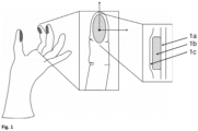
- the shaded area contains the sensor material.
- an enlargement of a finger segment according to the invention is shown, the viewing angle being along the surface normal.
- the right part of figure 1 depicts a multilayer structure of the finger segment according to the invention in cross section. This multilayer structure has a base layer (1a), a piezochromic sensor layer (1b) and a cover layer (1c).
- An anatomically shaped mold with at least one finger area can be used to manufacture the finger segment of a glove according to the invention.
- This molding tool can be supplemented with a palm area and a cuff area for manufacture as a glove.
- the mold can be designed to be variable in size.
- the mold can be made of a material suitable for dip coating and is preferably made of technical porcelain. The mold can be lowered into the respective immersion baths down to the preferred area of the mold and lifted out again after the respective dwell time.
- Salt solutions can be used as coagulation aids for separating polymers from a corresponding dispersion.
- the Layer thickness of the coating can be controlled on the one hand by the concentration of the salt solution in which the mold is first immersed, but also by the residence time in the polymer dispersion and its concentration in the subsequent immersion process step.
- the polymeric precursor in the dispersion is, for example, in the form of natural rubber or synthetic polyisoprenes and acrylonitrile-butadiene materials and combinations thereof. After being lifted out of the polymer dispersion, a polymer film of defined layer thickness has been deposited on the mold.
- the sensor material can be produced, for example, from a mixture of liquid crystal, optically active substance, network monomer, crosslinking agent and photoinitiator. This mixture independently forms a left-handed or right-handed helically ordered structure, which can also be controlled by thermal treatment.
- a preferred mixture contains the crosslinker at up to 20% by weight; Network monomer and liquid crystal up to 90% by weight, the photoinitiator up to 2% by weight and the optically active substance up to 30% by weight.
- Preferred liquid crystals are selected from the group consisting of cholesteryl benzoate, cholesterol, tolan, alkanoic acids, stilbene, azobenzenes, N-(p-ethoxy-benzylidene)-p-n-butylaniline, N-(p-methoxy-benzylidene)-p-n-butylaniline, derivatives of 4-n-alkylbenzoic acid (4-alkyl-phenyl ester), 4-phenylcinnamic acid, p-terphenyl, 1,2-bis-benzoylethene, liquid crystal mixtures of alkyl-cyanobiphenyl and alkoxycyanobiphenyl derivatives and mixtures thereof.
- optical activity can be achieved, for example, by adding 4-(4-hexyloxybenzoyloxy)benzoates or cholesteryl derivatives.
- Substances with an optically controlled radical formation mechanism are preferred as polymerization initiators over substances with a thermal radical formation behavior.
- These substances from the field of photoinitiators include, for example, benzil ketals, ⁇ -dialkoxyacetophenones, ⁇ -hydroxyalkylphenones, ⁇ -aminoalkylphenones, acylphosphine oxides or benzophenones, Irgacure 250 (BASF), Genocure LTM (Rahn) or Irgacure 2959 (SIGMA ALDRICH) .
- a preferred chiral liquid crystal phase can be obtained by mixing the components p-ethoxy(benzylidene)-p-n-butylaniline and N-(4-methoxybenzylidene)-4-butylaniline in a ratio of 3:1 if the total mixture contains the optically active substance (4- [[4-(hexyloxy)benzoyl]oxy]benzoic acid 2-octyl ester) at 30 percent by weight and is heated to over 50 °C for several minutes and then cooled.
- a preferred network-forming phase can be created by mixing methyl methacrylate with a 30% by weight mixture of 1,4-butanediol diacrylate and 1,10-decanediol diacrylate in a 1:2 ratio. 0.5% by weight of the photoinitiator Genocure LTM is added to this mixture and the mixture is then used further with the exclusion of light.
- the liquid crystalline phase and the network-forming phase are then combined and homogenized at over 50 °C for the coating processing.
- an orientation layer is first produced, which faces the sensor material.
- this layer can be produced by mechanical structuring by means of rubbing over a polyamide fiber web.
- the sensor material mixture is suitably applied to the prepared area of the overlay.
- a homogeneous layer with a uniform layer thickness can be produced in the desired area with the pad printing given here as an example.
- the phase behavior of the liquid-crystalline components can be adapted in this way by thermal treatment that a high degree of orientation is obtained in the output components of the sensor.
- the helical superstructure is stabilized by temperature and/or by chemical initiation, but ideally by light and thus by photochemical crosslinking of the reactive components.
- the mixture is irradiated with light of a wavelength distribution suitable for the photoinitiator, so that the radical formation takes place extensively. In this way, the mechanochromic sensor material is obtained.
- elastic photonic gratings can be used as sensor material. These can be produced, for example, by a process in which a lattice formed by depositing spherical silica particles on a carrier is used as a template phase. The thickness of the layer produced in this way is controlled via the process conditions of the deposition from the silica dispersion. The auxiliary grid thus obtained is dried and mechanically stabilized in a tetramethoxysilane atmosphere. The cavities between the lattice points are then filled with the monomeric components of the elastic network and photochemically polymerized to form the elastomeric network.
- ethylhexyl methacrylate is mixed with the crosslinking agent ethylene glycol dimethacrylate using the photoinitiator BAPO and reacted by irradiation with light in the range of 300 nm.
- the monofunctional monomer unit used can be replaced by lauryl, butyl and methyl derivatives, but also by butyl and hexyl acrylates, as well as mixtures of these components to adjust the mechanical responsiveness of the network.
- the composite produced in this way consisting of polymer network and auxiliary lattice, can now be brought into a desired shape.
- a washing process with a 2% strength aqueous hydrogen fluoride solution, which releases the inverse elastomer network, is preferably used to remove the silica template phase. This can be used dry and integrated in the desired area of the finger segment.
- the sensor material is preferably fully enclosed by renewed immersion in the coagulant solution and subsequent immersion in the polymer dispersion.
- the coating is then pulled off the mold so that the polymer layer previously lying on the mold points outwards and the last polymer layer produced faces the user - i.e. the finger or hand.
Landscapes
- Health & Medical Sciences (AREA)
- Surgery (AREA)
- Life Sciences & Earth Sciences (AREA)
- Engineering & Computer Science (AREA)
- Biomedical Technology (AREA)
- Heart & Thoracic Surgery (AREA)
- Medical Informatics (AREA)
- Molecular Biology (AREA)
- Animal Behavior & Ethology (AREA)
- General Health & Medical Sciences (AREA)
- Public Health (AREA)
- Veterinary Medicine (AREA)
- Physics & Mathematics (AREA)
- General Physics & Mathematics (AREA)
- Materials For Medical Uses (AREA)
Applications Claiming Priority (2)
| Application Number | Priority Date | Filing Date | Title |
|---|---|---|---|
| DE102018222633.4A DE102018222633A1 (de) | 2018-12-20 | 2018-12-20 | Fingersegment für einen Handschuh |
| PCT/EP2019/086699 WO2020127986A1 (de) | 2018-12-20 | 2019-12-20 | Fingersegment für einen handschuh |
Publications (2)
| Publication Number | Publication Date |
|---|---|
| EP3897441A1 EP3897441A1 (de) | 2021-10-27 |
| EP3897441B1 true EP3897441B1 (de) | 2023-05-03 |
Family
ID=69137888
Family Applications (1)
| Application Number | Title | Priority Date | Filing Date |
|---|---|---|---|
| EP19832385.9A Active EP3897441B1 (de) | 2018-12-20 | 2019-12-20 | Fingersegment für einen handschuh |
Country Status (4)
| Country | Link |
|---|---|
| EP (1) | EP3897441B1 (pl) |
| DE (1) | DE102018222633A1 (pl) |
| PL (1) | PL3897441T3 (pl) |
| WO (1) | WO2020127986A1 (pl) |
Family Cites Families (8)
| Publication number | Priority date | Publication date | Assignee | Title |
|---|---|---|---|---|
| DE102005009826A1 (de) | 2005-03-01 | 2006-09-07 | Krh-Kart Reifen Handel Dr. Peter Keller E.K. | Handschuh für medizinische Zwecke |
| US20070252115A1 (en) * | 2006-04-28 | 2007-11-01 | Arehart Kelly D | Thermochromic elastic articles |
| DE102007021014A1 (de) | 2007-05-04 | 2008-11-06 | Paul Hartmann Ag | Bereichsweise mehrlagiger medizinischer Handschuh |
| DE202009007671U1 (de) | 2009-05-29 | 2009-09-03 | Herms, Alexander | Schutzhandschuh mit Säure-/Base-Warnfunktion durch pH-Indikatoren |
| DE102009035363A1 (de) | 2009-07-30 | 2011-02-03 | Fraunhofer-Gesellschaft zur Förderung der angewandten Forschung e.V. | Piezochromes Material, piezochromer Verbundwerkstoff und piezochromer Sensor |
| JP4852167B1 (ja) * | 2010-09-01 | 2012-01-11 | 株式会社Icst | 触感鋭敏化グローブ |
| WO2016070078A1 (en) | 2014-10-30 | 2016-05-06 | Bebop Sensors, Inc. | Sensor system integrated with a glove |
| CA3048374A1 (en) * | 2017-01-24 | 2018-08-02 | Smarterials Technology Gmbh | Damage-resistant gloves with breach-indicator function |
-
2018
- 2018-12-20 DE DE102018222633.4A patent/DE102018222633A1/de not_active Ceased
-
2019
- 2019-12-20 PL PL19832385.9T patent/PL3897441T3/pl unknown
- 2019-12-20 EP EP19832385.9A patent/EP3897441B1/de active Active
- 2019-12-20 WO PCT/EP2019/086699 patent/WO2020127986A1/de not_active Ceased
Non-Patent Citations (1)
| Title |
|---|
| ARNO SEEBOTH ET AL: "Piezochromic Polymer Materials Displaying Pressure Changes in Bar-Ranges", AMERICAN JOURNAL OF MATERIALS SCIENCE, vol. 1, no. 2, 31 August 2012 (2012-08-31), pages 139 - 142, XP055200213, ISSN: 2162-9382, DOI: 10.5923/j.materials.20110102.23 * |
Also Published As
| Publication number | Publication date |
|---|---|
| DE102018222633A1 (de) | 2020-06-25 |
| PL3897441T3 (pl) | 2023-11-13 |
| EP3897441A1 (de) | 2021-10-27 |
| WO2020127986A1 (de) | 2020-06-25 |
Similar Documents
| Publication | Publication Date | Title |
|---|---|---|
| DE60011403T2 (de) | Bioadhesive zusammensetzungen | |
| EP2013311A1 (en) | Thermochromic elastic articles | |
| EP1966782A1 (de) | Simulationsvorrichtung zum simulieren von eindringvorgängen | |
| EP2152187B1 (de) | Bereichsweise mehrlagiger medizinischer handschuh | |
| DE68906352T2 (de) | Selbstklebende Bandage mit Rahmen. | |
| EP3897441B1 (de) | Fingersegment für einen handschuh | |
| DE69211594T2 (de) | Medizinische Barrierestoffe und Methode zur Herstellung | |
| Richter et al. | Shear bond strength of different adhesives tested in accordance with DIN 13990-1/-2 and using various methods of enamel conditioning | |
| EP2934348B1 (de) | Gefässverschlusssystem | |
| DE10226708A1 (de) | Pneumatisches Hautelastomer | |
| DE102013001732A1 (de) | Trägermittel zum Ankoppeln von zumindest einer Leit-Stütz-Struktur an einem Lebewesen | |
| WO2020020741A1 (de) | Lichthärtende polymerelektrode zur ableitung von biosignalen | |
| EP1274994B1 (de) | Verfahren zur herstellung eines pflasters für die bestimmung einer abnormalen hauttrockenheit | |
| EP4076314B1 (de) | Medizinischer artikel zur prophylaxe von dekubitalulcera | |
| DE102014105240A1 (de) | Modell und Verfahren zur Simulation einer perkutanen Nephrolitholapaxie sowie Verfahren zur Herstellung eines Gewebeimitationsmittels | |
| DE102009047886A1 (de) | Anatomisches Trainingsmodell für chirurgische Behandlungsverfahren | |
| DE102010022067A1 (de) | Aktuator- und/oder Sensorelement sowie Struktur und Manschette diese aufweisend | |
| WO1994028948A1 (de) | Kunststoffmischung enthaltend bariumsulfat zur absorption von röntgenstrahlen | |
| WO2005113232A1 (de) | Vlies-/folienlaminat | |
| DE10226532B3 (de) | In-vitro Messapparatur zur Druckermittlung bei Narbenreduktionspflastern | |
| DE102004037440A1 (de) | Vorrichtung zur Ermittlung von Funktionswerten | |
| Gallab et al. | A novel eye-surgery simulator of glaucoma surgery with a bionic eye model | |
| DE102021214743A1 (de) | Handschuh mit Indikator | |
| DE112023005436T5 (de) | Mehrschichtiges polymerprodukt mit einzeldonfunktion | |
| DE10203049B4 (de) | Gerät zur Messung sensibler Störungen bei Neuropathien |
Legal Events
| Date | Code | Title | Description |
|---|---|---|---|
| STAA | Information on the status of an ep patent application or granted ep patent |
Free format text: STATUS: UNKNOWN |
|
| STAA | Information on the status of an ep patent application or granted ep patent |
Free format text: STATUS: THE INTERNATIONAL PUBLICATION HAS BEEN MADE |
|
| PUAI | Public reference made under article 153(3) epc to a published international application that has entered the european phase |
Free format text: ORIGINAL CODE: 0009012 |
|
| STAA | Information on the status of an ep patent application or granted ep patent |
Free format text: STATUS: REQUEST FOR EXAMINATION WAS MADE |
|
| 17P | Request for examination filed |
Effective date: 20210720 |
|
| AK | Designated contracting states |
Kind code of ref document: A1 Designated state(s): AL AT BE BG CH CY CZ DE DK EE ES FI FR GB GR HR HU IE IS IT LI LT LU LV MC MK MT NL NO PL PT RO RS SE SI SK SM TR |
|
| DAV | Request for validation of the european patent (deleted) | ||
| DAX | Request for extension of the european patent (deleted) | ||
| STAA | Information on the status of an ep patent application or granted ep patent |
Free format text: STATUS: EXAMINATION IS IN PROGRESS |
|
| RAP3 | Party data changed (applicant data changed or rights of an application transferred) |
Owner name: WINDE, GUENTHER Owner name: FRAUNHOFER-GESELLSCHAFT ZUR FOERDERUNG DER ANGEWANDTEN FORSCHUNG E.V. |
|
| 17Q | First examination report despatched |
Effective date: 20220419 |
|
| RIC1 | Information provided on ipc code assigned before grant |
Ipc: G01L 1/24 20060101ALI20221012BHEP Ipc: A61B 90/00 20160101ALI20221012BHEP Ipc: A61B 34/00 20160101ALI20221012BHEP Ipc: G01L 5/00 20060101ALI20221012BHEP Ipc: A61B 42/20 20160101ALI20221012BHEP Ipc: A61B 42/10 20160101AFI20221012BHEP |
|
| GRAP | Despatch of communication of intention to grant a patent |
Free format text: ORIGINAL CODE: EPIDOSNIGR1 |
|
| STAA | Information on the status of an ep patent application or granted ep patent |
Free format text: STATUS: GRANT OF PATENT IS INTENDED |
|
| INTG | Intention to grant announced |
Effective date: 20221124 |
|
| GRAS | Grant fee paid |
Free format text: ORIGINAL CODE: EPIDOSNIGR3 |
|
| GRAA | (expected) grant |
Free format text: ORIGINAL CODE: 0009210 |
|
| STAA | Information on the status of an ep patent application or granted ep patent |
Free format text: STATUS: THE PATENT HAS BEEN GRANTED |
|
| AK | Designated contracting states |
Kind code of ref document: B1 Designated state(s): AL AT BE BG CH CY CZ DE DK EE ES FI FR GB GR HR HU IE IS IT LI LT LU LV MC MK MT NL NO PL PT RO RS SE SI SK SM TR |
|
| REG | Reference to a national code |
Ref country code: GB Ref legal event code: FG4D Free format text: NOT ENGLISH |
|
| REG | Reference to a national code |
Ref country code: AT Ref legal event code: REF Ref document number: 1563945 Country of ref document: AT Kind code of ref document: T Effective date: 20230515 Ref country code: CH Ref legal event code: EP |
|
| REG | Reference to a national code |
Ref country code: DE Ref legal event code: R096 Ref document number: 502019007654 Country of ref document: DE |
|
| REG | Reference to a national code |
Ref country code: IE Ref legal event code: FG4D Free format text: LANGUAGE OF EP DOCUMENT: GERMAN |
|
| REG | Reference to a national code |
Ref country code: LT Ref legal event code: MG9D |
|
| REG | Reference to a national code |
Ref country code: NL Ref legal event code: MP Effective date: 20230503 |
|
| PG25 | Lapsed in a contracting state [announced via postgrant information from national office to epo] |
Ref country code: SE Free format text: LAPSE BECAUSE OF FAILURE TO SUBMIT A TRANSLATION OF THE DESCRIPTION OR TO PAY THE FEE WITHIN THE PRESCRIBED TIME-LIMIT Effective date: 20230503 Ref country code: PT Free format text: LAPSE BECAUSE OF FAILURE TO SUBMIT A TRANSLATION OF THE DESCRIPTION OR TO PAY THE FEE WITHIN THE PRESCRIBED TIME-LIMIT Effective date: 20230904 Ref country code: NO Free format text: LAPSE BECAUSE OF FAILURE TO SUBMIT A TRANSLATION OF THE DESCRIPTION OR TO PAY THE FEE WITHIN THE PRESCRIBED TIME-LIMIT Effective date: 20230803 Ref country code: NL Free format text: LAPSE BECAUSE OF FAILURE TO SUBMIT A TRANSLATION OF THE DESCRIPTION OR TO PAY THE FEE WITHIN THE PRESCRIBED TIME-LIMIT Effective date: 20230503 Ref country code: ES Free format text: LAPSE BECAUSE OF FAILURE TO SUBMIT A TRANSLATION OF THE DESCRIPTION OR TO PAY THE FEE WITHIN THE PRESCRIBED TIME-LIMIT Effective date: 20230503 |
|
| PG25 | Lapsed in a contracting state [announced via postgrant information from national office to epo] |
Ref country code: RS Free format text: LAPSE BECAUSE OF FAILURE TO SUBMIT A TRANSLATION OF THE DESCRIPTION OR TO PAY THE FEE WITHIN THE PRESCRIBED TIME-LIMIT Effective date: 20230503 Ref country code: LV Free format text: LAPSE BECAUSE OF FAILURE TO SUBMIT A TRANSLATION OF THE DESCRIPTION OR TO PAY THE FEE WITHIN THE PRESCRIBED TIME-LIMIT Effective date: 20230503 Ref country code: LT Free format text: LAPSE BECAUSE OF FAILURE TO SUBMIT A TRANSLATION OF THE DESCRIPTION OR TO PAY THE FEE WITHIN THE PRESCRIBED TIME-LIMIT Effective date: 20230503 Ref country code: IS Free format text: LAPSE BECAUSE OF FAILURE TO SUBMIT A TRANSLATION OF THE DESCRIPTION OR TO PAY THE FEE WITHIN THE PRESCRIBED TIME-LIMIT Effective date: 20230903 Ref country code: HR Free format text: LAPSE BECAUSE OF FAILURE TO SUBMIT A TRANSLATION OF THE DESCRIPTION OR TO PAY THE FEE WITHIN THE PRESCRIBED TIME-LIMIT Effective date: 20230503 Ref country code: GR Free format text: LAPSE BECAUSE OF FAILURE TO SUBMIT A TRANSLATION OF THE DESCRIPTION OR TO PAY THE FEE WITHIN THE PRESCRIBED TIME-LIMIT Effective date: 20230804 |
|
| PG25 | Lapsed in a contracting state [announced via postgrant information from national office to epo] |
Ref country code: FI Free format text: LAPSE BECAUSE OF FAILURE TO SUBMIT A TRANSLATION OF THE DESCRIPTION OR TO PAY THE FEE WITHIN THE PRESCRIBED TIME-LIMIT Effective date: 20230503 |
|
| PG25 | Lapsed in a contracting state [announced via postgrant information from national office to epo] |
Ref country code: SK Free format text: LAPSE BECAUSE OF FAILURE TO SUBMIT A TRANSLATION OF THE DESCRIPTION OR TO PAY THE FEE WITHIN THE PRESCRIBED TIME-LIMIT Effective date: 20230503 |
|
| PG25 | Lapsed in a contracting state [announced via postgrant information from national office to epo] |
Ref country code: SM Free format text: LAPSE BECAUSE OF FAILURE TO SUBMIT A TRANSLATION OF THE DESCRIPTION OR TO PAY THE FEE WITHIN THE PRESCRIBED TIME-LIMIT Effective date: 20230503 Ref country code: SK Free format text: LAPSE BECAUSE OF FAILURE TO SUBMIT A TRANSLATION OF THE DESCRIPTION OR TO PAY THE FEE WITHIN THE PRESCRIBED TIME-LIMIT Effective date: 20230503 Ref country code: RO Free format text: LAPSE BECAUSE OF FAILURE TO SUBMIT A TRANSLATION OF THE DESCRIPTION OR TO PAY THE FEE WITHIN THE PRESCRIBED TIME-LIMIT Effective date: 20230503 Ref country code: EE Free format text: LAPSE BECAUSE OF FAILURE TO SUBMIT A TRANSLATION OF THE DESCRIPTION OR TO PAY THE FEE WITHIN THE PRESCRIBED TIME-LIMIT Effective date: 20230503 Ref country code: DK Free format text: LAPSE BECAUSE OF FAILURE TO SUBMIT A TRANSLATION OF THE DESCRIPTION OR TO PAY THE FEE WITHIN THE PRESCRIBED TIME-LIMIT Effective date: 20230503 Ref country code: CZ Free format text: LAPSE BECAUSE OF FAILURE TO SUBMIT A TRANSLATION OF THE DESCRIPTION OR TO PAY THE FEE WITHIN THE PRESCRIBED TIME-LIMIT Effective date: 20230503 |
|
| REG | Reference to a national code |
Ref country code: DE Ref legal event code: R097 Ref document number: 502019007654 Country of ref document: DE |
|
| PLBE | No opposition filed within time limit |
Free format text: ORIGINAL CODE: 0009261 |
|
| STAA | Information on the status of an ep patent application or granted ep patent |
Free format text: STATUS: NO OPPOSITION FILED WITHIN TIME LIMIT |
|
| 26N | No opposition filed |
Effective date: 20240206 |
|
| PG25 | Lapsed in a contracting state [announced via postgrant information from national office to epo] |
Ref country code: SI Free format text: LAPSE BECAUSE OF FAILURE TO SUBMIT A TRANSLATION OF THE DESCRIPTION OR TO PAY THE FEE WITHIN THE PRESCRIBED TIME-LIMIT Effective date: 20230503 |
|
| PG25 | Lapsed in a contracting state [announced via postgrant information from national office to epo] |
Ref country code: SI Free format text: LAPSE BECAUSE OF FAILURE TO SUBMIT A TRANSLATION OF THE DESCRIPTION OR TO PAY THE FEE WITHIN THE PRESCRIBED TIME-LIMIT Effective date: 20230503 Ref country code: IT Free format text: LAPSE BECAUSE OF FAILURE TO SUBMIT A TRANSLATION OF THE DESCRIPTION OR TO PAY THE FEE WITHIN THE PRESCRIBED TIME-LIMIT Effective date: 20230503 |
|
| PGFP | Annual fee paid to national office [announced via postgrant information from national office to epo] |
Ref country code: IE Payment date: 20240530 Year of fee payment: 5 |
|
| REG | Reference to a national code |
Ref country code: CH Ref legal event code: PL |
|
| PG25 | Lapsed in a contracting state [announced via postgrant information from national office to epo] |
Ref country code: LU Free format text: LAPSE BECAUSE OF NON-PAYMENT OF DUE FEES Effective date: 20231220 |
|
| PG25 | Lapsed in a contracting state [announced via postgrant information from national office to epo] |
Ref country code: MC Free format text: LAPSE BECAUSE OF FAILURE TO SUBMIT A TRANSLATION OF THE DESCRIPTION OR TO PAY THE FEE WITHIN THE PRESCRIBED TIME-LIMIT Effective date: 20230503 |
|
| GBPC | Gb: european patent ceased through non-payment of renewal fee |
Effective date: 20231220 |
|
| REG | Reference to a national code |
Ref country code: BE Ref legal event code: MM Effective date: 20231231 |
|
| PG25 | Lapsed in a contracting state [announced via postgrant information from national office to epo] |
Ref country code: MC Free format text: LAPSE BECAUSE OF FAILURE TO SUBMIT A TRANSLATION OF THE DESCRIPTION OR TO PAY THE FEE WITHIN THE PRESCRIBED TIME-LIMIT Effective date: 20230503 Ref country code: LU Free format text: LAPSE BECAUSE OF NON-PAYMENT OF DUE FEES Effective date: 20231220 |
|
| PG25 | Lapsed in a contracting state [announced via postgrant information from national office to epo] |
Ref country code: GB Free format text: LAPSE BECAUSE OF NON-PAYMENT OF DUE FEES Effective date: 20231220 |
|
| PG25 | Lapsed in a contracting state [announced via postgrant information from national office to epo] |
Ref country code: BE Free format text: LAPSE BECAUSE OF NON-PAYMENT OF DUE FEES Effective date: 20231231 |
|
| PG25 | Lapsed in a contracting state [announced via postgrant information from national office to epo] |
Ref country code: CH Free format text: LAPSE BECAUSE OF NON-PAYMENT OF DUE FEES Effective date: 20231231 |
|
| PG25 | Lapsed in a contracting state [announced via postgrant information from national office to epo] |
Ref country code: GB Free format text: LAPSE BECAUSE OF NON-PAYMENT OF DUE FEES Effective date: 20231220 Ref country code: CH Free format text: LAPSE BECAUSE OF NON-PAYMENT OF DUE FEES Effective date: 20231231 Ref country code: BE Free format text: LAPSE BECAUSE OF NON-PAYMENT OF DUE FEES Effective date: 20231231 |
|
| PG25 | Lapsed in a contracting state [announced via postgrant information from national office to epo] |
Ref country code: BG Free format text: LAPSE BECAUSE OF FAILURE TO SUBMIT A TRANSLATION OF THE DESCRIPTION OR TO PAY THE FEE WITHIN THE PRESCRIBED TIME-LIMIT Effective date: 20230503 |
|
| PG25 | Lapsed in a contracting state [announced via postgrant information from national office to epo] |
Ref country code: BG Free format text: LAPSE BECAUSE OF FAILURE TO SUBMIT A TRANSLATION OF THE DESCRIPTION OR TO PAY THE FEE WITHIN THE PRESCRIBED TIME-LIMIT Effective date: 20230503 |
|
| PGFP | Annual fee paid to national office [announced via postgrant information from national office to epo] |
Ref country code: TR Payment date: 20241217 Year of fee payment: 6 |
|
| PG25 | Lapsed in a contracting state [announced via postgrant information from national office to epo] |
Ref country code: CY Free format text: LAPSE BECAUSE OF FAILURE TO SUBMIT A TRANSLATION OF THE DESCRIPTION OR TO PAY THE FEE WITHIN THE PRESCRIBED TIME-LIMIT; INVALID AB INITIO Effective date: 20191220 |
|
| PG25 | Lapsed in a contracting state [announced via postgrant information from national office to epo] |
Ref country code: HU Free format text: LAPSE BECAUSE OF FAILURE TO SUBMIT A TRANSLATION OF THE DESCRIPTION OR TO PAY THE FEE WITHIN THE PRESCRIBED TIME-LIMIT; INVALID AB INITIO Effective date: 20191220 |
|
| PG25 | Lapsed in a contracting state [announced via postgrant information from national office to epo] |
Ref country code: IE Free format text: LAPSE BECAUSE OF NON-PAYMENT OF DUE FEES Effective date: 20241220 |
|
| PGFP | Annual fee paid to national office [announced via postgrant information from national office to epo] |
Ref country code: DE Payment date: 20251216 Year of fee payment: 7 |
|
| PGFP | Annual fee paid to national office [announced via postgrant information from national office to epo] |
Ref country code: AT Payment date: 20251222 Year of fee payment: 7 |
|
| PGFP | Annual fee paid to national office [announced via postgrant information from national office to epo] |
Ref country code: FR Payment date: 20251229 Year of fee payment: 7 |
|
| PGFP | Annual fee paid to national office [announced via postgrant information from national office to epo] |
Ref country code: PL Payment date: 20251215 Year of fee payment: 7 |