EP3897441B1 - Finger segment for a glove - Google Patents
Finger segment for a glove Download PDFInfo
- Publication number
- EP3897441B1 EP3897441B1 EP19832385.9A EP19832385A EP3897441B1 EP 3897441 B1 EP3897441 B1 EP 3897441B1 EP 19832385 A EP19832385 A EP 19832385A EP 3897441 B1 EP3897441 B1 EP 3897441B1
- Authority
- EP
- European Patent Office
- Prior art keywords
- sensor material
- finger segment
- finger
- segment according
- sensor
- Prior art date
- Legal status (The legal status is an assumption and is not a legal conclusion. Google has not performed a legal analysis and makes no representation as to the accuracy of the status listed.)
- Active
Links
- 239000000463 material Substances 0.000 claims description 67
- 239000000203 mixture Substances 0.000 claims description 30
- 230000008859 change Effects 0.000 claims description 21
- 239000004973 liquid crystal related substance Substances 0.000 claims description 13
- 230000000694 effects Effects 0.000 claims description 11
- 238000004519 manufacturing process Methods 0.000 claims description 10
- 239000000178 monomer Substances 0.000 claims description 10
- 239000013543 active substance Substances 0.000 claims description 9
- HVYWMOMLDIMFJA-DPAQBDIFSA-N cholesterol Chemical compound C1C=C2C[C@@H](O)CC[C@]2(C)[C@@H]2[C@@H]1[C@@H]1CC[C@H]([C@H](C)CCCC(C)C)[C@@]1(C)CC2 HVYWMOMLDIMFJA-DPAQBDIFSA-N 0.000 claims description 9
- 230000035945 sensitivity Effects 0.000 claims description 9
- 239000004971 Cross linker Substances 0.000 claims description 8
- 229920000642 polymer Polymers 0.000 claims description 8
- 238000000034 method Methods 0.000 claims description 7
- 239000002253 acid Substances 0.000 claims description 6
- -1 polyethylene Polymers 0.000 claims description 5
- 238000005507 spraying Methods 0.000 claims description 5
- RHNJVKIVSXGYBD-UHFFFAOYSA-N 10-prop-2-enoyloxydecyl prop-2-enoate Chemical compound C=CC(=O)OCCCCCCCCCCOC(=O)C=C RHNJVKIVSXGYBD-UHFFFAOYSA-N 0.000 claims description 4
- JHWGFJBTMHEZME-UHFFFAOYSA-N 4-prop-2-enoyloxybutyl prop-2-enoate Chemical group C=CC(=O)OCCCCOC(=O)C=C JHWGFJBTMHEZME-UHFFFAOYSA-N 0.000 claims description 4
- 150000001875 compounds Chemical class 0.000 claims description 4
- 238000007598 dipping method Methods 0.000 claims description 4
- 238000007639 printing Methods 0.000 claims description 4
- 238000001228 spectrum Methods 0.000 claims description 4
- DMJDEZUEYXVYNO-DHZHZOJOSA-N (e)-3-(4-phenylphenyl)prop-2-enoic acid Chemical compound C1=CC(/C=C/C(=O)O)=CC=C1C1=CC=CC=C1 DMJDEZUEYXVYNO-DHZHZOJOSA-N 0.000 claims description 3
- XJKSTNDFUHDPQJ-UHFFFAOYSA-N 1,4-diphenylbenzene Chemical group C1=CC=CC=C1C1=CC=C(C=2C=CC=CC=2)C=C1 XJKSTNDFUHDPQJ-UHFFFAOYSA-N 0.000 claims description 3
- WYCXGQSQHAXLPK-UHFFFAOYSA-N 1,4-diphenylbut-2-ene-1,4-dione Chemical compound C=1C=CC=CC=1C(=O)C=CC(=O)C1=CC=CC=C1 WYCXGQSQHAXLPK-UHFFFAOYSA-N 0.000 claims description 3
- GOXQRTZXKQZDDN-UHFFFAOYSA-N 2-Ethylhexyl acrylate Chemical compound CCCCC(CC)COC(=O)C=C GOXQRTZXKQZDDN-UHFFFAOYSA-N 0.000 claims description 3
- HFCUBKYHMMPGBY-UHFFFAOYSA-N 2-methoxyethyl prop-2-enoate Chemical compound COCCOC(=O)C=C HFCUBKYHMMPGBY-UHFFFAOYSA-N 0.000 claims description 3
- VQLWORYWCJWAAP-UHFFFAOYSA-N 4-(4-hexoxybenzoyl)oxybenzoic acid Chemical compound C1=CC(OCCCCCC)=CC=C1C(=O)OC1=CC=C(C(O)=O)C=C1 VQLWORYWCJWAAP-UHFFFAOYSA-N 0.000 claims description 3
- 239000002202 Polyethylene glycol Substances 0.000 claims description 3
- PJANXHGTPQOBST-VAWYXSNFSA-N Stilbene Natural products C=1C=CC=CC=1/C=C/C1=CC=CC=C1 PJANXHGTPQOBST-VAWYXSNFSA-N 0.000 claims description 3
- 239000012965 benzophenone Substances 0.000 claims description 3
- 150000008366 benzophenones Chemical class 0.000 claims description 3
- AOJOEFVRHOZDFN-UHFFFAOYSA-N benzyl 2-methylprop-2-enoate Chemical compound CC(=C)C(=O)OCC1=CC=CC=C1 AOJOEFVRHOZDFN-UHFFFAOYSA-N 0.000 claims description 3
- JRXXLCKWQFKACW-UHFFFAOYSA-N biphenylacetylene Chemical compound C1=CC=CC=C1C#CC1=CC=CC=C1 JRXXLCKWQFKACW-UHFFFAOYSA-N 0.000 claims description 3
- 235000012000 cholesterol Nutrition 0.000 claims description 3
- 125000004386 diacrylate group Chemical group 0.000 claims description 3
- 239000004816 latex Substances 0.000 claims description 3
- 229920000126 latex Polymers 0.000 claims description 3
- FEIWNULTQYHCDN-UHFFFAOYSA-N mbba Chemical compound C1=CC(CCCC)=CC=C1N=CC1=CC=C(OC)C=C1 FEIWNULTQYHCDN-UHFFFAOYSA-N 0.000 claims description 3
- FSAJWMJJORKPKS-UHFFFAOYSA-N octadecyl prop-2-enoate Chemical compound CCCCCCCCCCCCCCCCCCOC(=O)C=C FSAJWMJJORKPKS-UHFFFAOYSA-N 0.000 claims description 3
- 229930184652 p-Terphenyl Natural products 0.000 claims description 3
- 229920001223 polyethylene glycol Polymers 0.000 claims description 3
- 230000002441 reversible effect Effects 0.000 claims description 3
- PJANXHGTPQOBST-UHFFFAOYSA-N stilbene Chemical compound C=1C=CC=CC=1C=CC1=CC=CC=C1 PJANXHGTPQOBST-UHFFFAOYSA-N 0.000 claims description 3
- 235000021286 stilbenes Nutrition 0.000 claims description 3
- 230000001960 triggered effect Effects 0.000 claims description 3
- 239000004698 Polyethylene Substances 0.000 claims description 2
- 239000002174 Styrene-butadiene Substances 0.000 claims description 2
- MTAZNLWOLGHBHU-UHFFFAOYSA-N butadiene-styrene rubber Chemical compound C=CC=C.C=CC1=CC=CC=C1 MTAZNLWOLGHBHU-UHFFFAOYSA-N 0.000 claims description 2
- 239000003086 colorant Substances 0.000 claims description 2
- 230000001965 increasing effect Effects 0.000 claims description 2
- 230000002427 irreversible effect Effects 0.000 claims description 2
- DBOAVDSSZWDGTH-UHFFFAOYSA-N n-(4-butylphenyl)-1-(4-ethoxyphenyl)methanimine Chemical compound C1=CC(CCCC)=CC=C1N=CC1=CC=C(OCC)C=C1 DBOAVDSSZWDGTH-UHFFFAOYSA-N 0.000 claims description 2
- 230000003287 optical effect Effects 0.000 claims description 2
- 229920001084 poly(chloroprene) Polymers 0.000 claims description 2
- 229920000573 polyethylene Polymers 0.000 claims description 2
- 239000011115 styrene butadiene Substances 0.000 claims description 2
- 229920003048 styrene butadiene rubber Polymers 0.000 claims description 2
- 239000012858 resilient material Substances 0.000 claims 9
- WPYMKLBDIGXBTP-UHFFFAOYSA-N Benzoic acid Natural products OC(=O)C1=CC=CC=C1 WPYMKLBDIGXBTP-UHFFFAOYSA-N 0.000 claims 1
- 239000005711 Benzoic acid Substances 0.000 claims 1
- 150000008062 acetophenones Chemical class 0.000 claims 1
- 235000010233 benzoic acid Nutrition 0.000 claims 1
- 239000010410 layer Substances 0.000 description 29
- 239000013013 elastic material Substances 0.000 description 9
- 238000000576 coating method Methods 0.000 description 7
- 239000011248 coating agent Substances 0.000 description 6
- 230000006870 function Effects 0.000 description 5
- 239000000126 substance Substances 0.000 description 5
- VYPSYNLAJGMNEJ-UHFFFAOYSA-N Silicium dioxide Chemical compound O=[Si]=O VYPSYNLAJGMNEJ-UHFFFAOYSA-N 0.000 description 4
- 238000007654 immersion Methods 0.000 description 4
- 230000008569 process Effects 0.000 description 4
- 239000000243 solution Substances 0.000 description 4
- 230000015572 biosynthetic process Effects 0.000 description 3
- 239000004815 dispersion polymer Substances 0.000 description 3
- 229920001971 elastomer Polymers 0.000 description 3
- 230000010354 integration Effects 0.000 description 3
- 230000001681 protective effect Effects 0.000 description 3
- 239000003356 suture material Substances 0.000 description 3
- 210000001519 tissue Anatomy 0.000 description 3
- GJKGAPPUXSSCFI-UHFFFAOYSA-N 2-Hydroxy-4'-(2-hydroxyethoxy)-2-methylpropiophenone Chemical compound CC(C)(O)C(=O)C1=CC=C(OCCO)C=C1 GJKGAPPUXSSCFI-UHFFFAOYSA-N 0.000 description 2
- KFZMGEQAYNKOFK-UHFFFAOYSA-N Isopropanol Chemical compound CC(C)O KFZMGEQAYNKOFK-UHFFFAOYSA-N 0.000 description 2
- 150000007513 acids Chemical class 0.000 description 2
- 230000009471 action Effects 0.000 description 2
- WURBFLDFSFBTLW-UHFFFAOYSA-N benzil Chemical compound C=1C=CC=CC=1C(=O)C(=O)C1=CC=CC=C1 WURBFLDFSFBTLW-UHFFFAOYSA-N 0.000 description 2
- 125000000484 butyl group Chemical group [H]C([*])([H])C([H])([H])C([H])([H])C([H])([H])[H] 0.000 description 2
- UVZUFUGNHDDLRQ-LLHZKFLPSA-N cholesteryl benzoate Chemical compound O([C@@H]1CC2=CC[C@H]3[C@@H]4CC[C@@H]([C@]4(CC[C@@H]3[C@@]2(C)CC1)C)[C@H](C)CCCC(C)C)C(=O)C1=CC=CC=C1 UVZUFUGNHDDLRQ-LLHZKFLPSA-N 0.000 description 2
- 239000003431 cross linking reagent Substances 0.000 description 2
- 230000001419 dependent effect Effects 0.000 description 2
- 238000000151 deposition Methods 0.000 description 2
- 239000006185 dispersion Substances 0.000 description 2
- 238000002156 mixing Methods 0.000 description 2
- KJFMBFZCATUALV-UHFFFAOYSA-N phenolphthalein Chemical compound C1=CC(O)=CC=C1C1(C=2C=CC(O)=CC=2)C2=CC=CC=C2C(=O)O1 KJFMBFZCATUALV-UHFFFAOYSA-N 0.000 description 2
- 239000004033 plastic Substances 0.000 description 2
- 229920003023 plastic Polymers 0.000 description 2
- 239000002861 polymer material Substances 0.000 description 2
- 239000013047 polymeric layer Substances 0.000 description 2
- 230000002787 reinforcement Effects 0.000 description 2
- 239000005060 rubber Substances 0.000 description 2
- 239000012266 salt solution Substances 0.000 description 2
- 238000001356 surgical procedure Methods 0.000 description 2
- 230000001225 therapeutic effect Effects 0.000 description 2
- 238000007669 thermal treatment Methods 0.000 description 2
- 238000012549 training Methods 0.000 description 2
- 238000012800 visualization Methods 0.000 description 2
- PLGPDUBTEHIWRH-UHFFFAOYSA-N (4-octan-2-yloxycarbonylphenyl) 4-hexoxybenzoate Chemical compound C1=CC(OCCCCCC)=CC=C1C(=O)OC1=CC=C(C(=O)OC(C)CCCCCC)C=C1 PLGPDUBTEHIWRH-UHFFFAOYSA-N 0.000 description 1
- MBXSHBIQMDKTEW-UHFFFAOYSA-N 3-bromobutanenitrile Chemical compound CC(Br)CC#N MBXSHBIQMDKTEW-UHFFFAOYSA-N 0.000 description 1
- XDLMVUHYZWKMMD-UHFFFAOYSA-N 3-trimethoxysilylpropyl 2-methylprop-2-enoate Chemical compound CO[Si](OC)(OC)CCCOC(=O)C(C)=C XDLMVUHYZWKMMD-UHFFFAOYSA-N 0.000 description 1
- DBCAQXHNJOFNGC-UHFFFAOYSA-N 4-bromo-1,1,1-trifluorobutane Chemical compound FC(F)(F)CCCBr DBCAQXHNJOFNGC-UHFFFAOYSA-N 0.000 description 1
- KRHYYFGTRYWZRS-UHFFFAOYSA-N Fluorane Chemical compound F KRHYYFGTRYWZRS-UHFFFAOYSA-N 0.000 description 1
- 244000043261 Hevea brasiliensis Species 0.000 description 1
- CERQOIWHTDAKMF-UHFFFAOYSA-N Methacrylic acid Chemical compound CC(=C)C(O)=O CERQOIWHTDAKMF-UHFFFAOYSA-N 0.000 description 1
- VVQNEPGJFQJSBK-UHFFFAOYSA-N Methyl methacrylate Chemical compound COC(=O)C(C)=C VVQNEPGJFQJSBK-UHFFFAOYSA-N 0.000 description 1
- 239000005183 N-(4-Methoxybenzylidene)-4-butylaniline Substances 0.000 description 1
- 229920000459 Nitrile rubber Polymers 0.000 description 1
- 239000004952 Polyamide Substances 0.000 description 1
- 229910004298 SiO 2 Inorganic materials 0.000 description 1
- 208000002847 Surgical Wound Diseases 0.000 description 1
- 206010052428 Wound Diseases 0.000 description 1
- 208000027418 Wounds and injury Diseases 0.000 description 1
- 238000004026 adhesive bonding Methods 0.000 description 1
- 230000002411 adverse Effects 0.000 description 1
- NTXGQCSETZTARF-UHFFFAOYSA-N buta-1,3-diene;prop-2-enenitrile Chemical compound C=CC=C.C=CC#N NTXGQCSETZTARF-UHFFFAOYSA-N 0.000 description 1
- 239000000701 coagulant Substances 0.000 description 1
- 230000015271 coagulation Effects 0.000 description 1
- 238000005345 coagulation Methods 0.000 description 1
- 239000002131 composite material Substances 0.000 description 1
- 238000004132 cross linking Methods 0.000 description 1
- 230000007547 defect Effects 0.000 description 1
- 230000008021 deposition Effects 0.000 description 1
- 238000013461 design Methods 0.000 description 1
- 238000003618 dip coating Methods 0.000 description 1
- 238000009826 distribution Methods 0.000 description 1
- 125000003438 dodecyl group Chemical group [H]C([H])([H])C([H])([H])C([H])([H])C([H])([H])C([H])([H])C([H])([H])C([H])([H])C([H])([H])C([H])([H])C([H])([H])C([H])([H])C([H])([H])* 0.000 description 1
- 239000000806 elastomer Substances 0.000 description 1
- STVZJERGLQHEKB-UHFFFAOYSA-N ethylene glycol dimethacrylate Substances CC(=C)C(=O)OCCOC(=O)C(C)=C STVZJERGLQHEKB-UHFFFAOYSA-N 0.000 description 1
- 230000007717 exclusion Effects 0.000 description 1
- 239000004744 fabric Substances 0.000 description 1
- 239000000835 fiber Substances 0.000 description 1
- 238000007306 functionalization reaction Methods 0.000 description 1
- LNMQRPPRQDGUDR-UHFFFAOYSA-N hexyl prop-2-enoate Chemical class CCCCCCOC(=O)C=C LNMQRPPRQDGUDR-UHFFFAOYSA-N 0.000 description 1
- 229910000040 hydrogen fluoride Inorganic materials 0.000 description 1
- 230000000977 initiatory effect Effects 0.000 description 1
- 230000000968 intestinal effect Effects 0.000 description 1
- 239000007788 liquid Substances 0.000 description 1
- 210000004185 liver Anatomy 0.000 description 1
- 230000007246 mechanism Effects 0.000 description 1
- 125000002496 methyl group Chemical group [H]C([H])([H])* 0.000 description 1
- 238000000465 moulding Methods 0.000 description 1
- 210000003205 muscle Anatomy 0.000 description 1
- LTZQZQSGQBNBFB-UHFFFAOYSA-N n-(4-butyl-4-ethoxycyclohexa-1,5-dien-1-yl)-1-phenylmethanimine Chemical compound C1=CC(CCCC)(OCC)CC=C1N=CC1=CC=CC=C1 LTZQZQSGQBNBFB-UHFFFAOYSA-N 0.000 description 1
- 239000002105 nanoparticle Substances 0.000 description 1
- 229920003052 natural elastomer Polymers 0.000 description 1
- 229920001194 natural rubber Polymers 0.000 description 1
- 230000000474 nursing effect Effects 0.000 description 1
- KCAMXZBMXVIIQN-UHFFFAOYSA-N octan-3-yl 2-methylprop-2-enoate Chemical compound CCCCCC(CC)OC(=O)C(C)=C KCAMXZBMXVIIQN-UHFFFAOYSA-N 0.000 description 1
- 238000007649 pad printing Methods 0.000 description 1
- 230000008447 perception Effects 0.000 description 1
- 239000007793 ph indicator Substances 0.000 description 1
- 238000000554 physical therapy Methods 0.000 description 1
- 229920002647 polyamide Polymers 0.000 description 1
- 229920006254 polymer film Polymers 0.000 description 1
- 239000012704 polymeric precursor Substances 0.000 description 1
- 239000003505 polymerization initiator Substances 0.000 description 1
- 229920000915 polyvinyl chloride Polymers 0.000 description 1
- 239000004800 polyvinyl chloride Substances 0.000 description 1
- 229910052573 porcelain Inorganic materials 0.000 description 1
- 238000012545 processing Methods 0.000 description 1
- 230000004043 responsiveness Effects 0.000 description 1
- 239000000377 silicon dioxide Substances 0.000 description 1
- 229920003051 synthetic elastomer Polymers 0.000 description 1
- BFKJFAAPBSQJPD-UHFFFAOYSA-N tetrafluoroethene Chemical group FC(F)=C(F)F BFKJFAAPBSQJPD-UHFFFAOYSA-N 0.000 description 1
- LFQCEHFDDXELDD-UHFFFAOYSA-N tetramethyl orthosilicate Chemical compound CO[Si](OC)(OC)OC LFQCEHFDDXELDD-UHFFFAOYSA-N 0.000 description 1
- 210000000115 thoracic cavity Anatomy 0.000 description 1
- ZNOCGWVLWPVKAO-UHFFFAOYSA-N trimethoxy(phenyl)silane Chemical compound CO[Si](OC)(OC)C1=CC=CC=C1 ZNOCGWVLWPVKAO-UHFFFAOYSA-N 0.000 description 1
- 230000002792 vascular Effects 0.000 description 1
- 230000009278 visceral effect Effects 0.000 description 1
- 238000005406 washing Methods 0.000 description 1
Images
Classifications
-
- A—HUMAN NECESSITIES
- A61—MEDICAL OR VETERINARY SCIENCE; HYGIENE
- A61B—DIAGNOSIS; SURGERY; IDENTIFICATION
- A61B42/00—Surgical gloves; Finger-stalls specially adapted for surgery; Devices for handling or treatment thereof
- A61B42/10—Surgical gloves
-
- A—HUMAN NECESSITIES
- A61—MEDICAL OR VETERINARY SCIENCE; HYGIENE
- A61B—DIAGNOSIS; SURGERY; IDENTIFICATION
- A61B42/00—Surgical gloves; Finger-stalls specially adapted for surgery; Devices for handling or treatment thereof
- A61B42/20—Finger-stalls specially adapted for surgery
-
- G—PHYSICS
- G01—MEASURING; TESTING
- G01L—MEASURING FORCE, STRESS, TORQUE, WORK, MECHANICAL POWER, MECHANICAL EFFICIENCY, OR FLUID PRESSURE
- G01L1/00—Measuring force or stress, in general
- G01L1/24—Measuring force or stress, in general by measuring variations of optical properties of material when it is stressed, e.g. by photoelastic stress analysis using infrared, visible light, ultraviolet
- G01L1/247—Measuring force or stress, in general by measuring variations of optical properties of material when it is stressed, e.g. by photoelastic stress analysis using infrared, visible light, ultraviolet using distributed sensing elements, e.g. microcapsules
-
- A—HUMAN NECESSITIES
- A61—MEDICAL OR VETERINARY SCIENCE; HYGIENE
- A61B—DIAGNOSIS; SURGERY; IDENTIFICATION
- A61B90/00—Instruments, implements or accessories specially adapted for surgery or diagnosis and not covered by any of the groups A61B1/00 - A61B50/00, e.g. for luxation treatment or for protecting wound edges
- A61B90/06—Measuring instruments not otherwise provided for
- A61B2090/064—Measuring instruments not otherwise provided for for measuring force, pressure or mechanical tension
- A61B2090/065—Measuring instruments not otherwise provided for for measuring force, pressure or mechanical tension for measuring contact or contact pressure
Definitions
- the present invention relates to a finger segment for a glove for medical and diagnostic purposes, which contains a sensor material which, when subjected to a mechanical force, undergoes a characteristic change which can be recognized by the user without technical aids. Furthermore, the present invention relates to a glove that has this finger segment and uses of the finger segment or the glove.
- Medical gloves or finger segments for these gloves are used in almost all medical care situations and serve to avoid direct contact between the patient and the user. They are made of a polymer material and are intended for single use. These gloves are manufactured in sterile and non-sterile versions and are part of the personal protective equipment for medical and nursing staff. A snug fit ensures high wearing comfort but also an unimpaired haptic perception guaranteed. Diagnostic and therapeutic tasks can be easily performed with these gloves.
- the integration of additional functions is advantageous for special medical tasks.
- the integration of additional functions in a medical glove for the production of a surgical seam is particularly important.
- the surgeon creates a surgical suture.
- the edges of the wound are first connected to one another with the suture material.
- direct contact is made between the edges without damaging adjacent tissue.
- the suture is then secured with a surgical knot.
- the process requires a precise use of force by the surgeon.
- the suture material is guided over a finger, which transmits the tensile force to the suture and knot.
- the thread exerts pressure on its contact surface. This pressure is therefore a measure of the tensile force that is exerted.
- the required tensile forces and resulting contact pressures vary with the type of fabric to be sewn. When dosing the force, the surgeon relies purely on empirical values. Especially beginners find it very difficult to estimate the required force. There are currently no technical tools that can be used appropriately to provide support.
- the present invention is aimed at application scenarios, in particular in the medical field, in which it is necessary to meter forces exerted by hand or fingers precisely.
- fields of application are, for example, in the training and further education of physicians and therapeutic staff.
- WO 2018/138095 A1 discloses a double layer glove which can visually indicate a defect in the material (according to the preamble of claim 1).
- DE 10 2005 009 826 A1 relates to a glove for medical purposes, in particular a protective glove for use in medical diagnostic examinations of/in body cavities of a patient, consisting of a thin elastic layer, in particular rubber, plastic or latex layer, tightly enclosing the examiner's hand receiving areas formed thereon for the fingers, wherein at least the layer thickness of the receiving area for the middle finger is either reinforced or double-walled at least in some areas compared to the palm receiving area.
- WO 2008/135213 A1 describes a disposable multilayer medical glove made of polymeric material with a finger area, a palm area and a cuff area, with a front section with a closed end and a rear section with an open end, wherein the front section contains the finger area completely and the palm area at least partially and wherein a first inner polymeric layer comprising the front section and the rear section and wherein the inner layer is coated in the front section with a second outer polymeric layer to form a reinforcement area and the reinforcement area defines and defines the front section.
- WO 2016/070078 A1 discloses sensor systems designed to be integrated into human hand gloves.
- An array of sensors detects forces associated with the action of a hand in the glove, and associated circuitry generates corresponding control information that can be used to control a wide variety of processes and devices.
- DE 10 2010 019 573 A1 describes a protective glove that consists of an acid/base-resistant material, on the surface of which there is a coating that contains pH indicators that change color at pH values that are dangerous for the skin, and that the coating consists of a solution of 3-methacryloxypropyltrimethoxysilane, SiO 2 nanoparticles, phenyltrimethoxysilane, isopropanol, methacrylic acid, a radical photostarter solution and sulfonated tetrafluoroethylene polymers, phenolphthalein and bromocresol green sodium salt is applied to the glove by spraying or flooding and curing takes place using a UV lamp .
- the object of the present invention was to provide a finger segment for a glove which allows the user to meter the force exerted as precisely as possible without requiring technical aids for this purpose.
- This object is solved by the finger segment for a glove for diagnostic and medical purposes with the features of claim 1.
- This finger segment contains an elastic material enclosing the user's finger and a sensor material enclosed by the elastic material, the sensor material being suitable for displaying an acting mechanical force and the sensor material undergoing a change that is characteristic of the acting mechanical force and which the user does not notice without technical aids can be identified.
- the finger segment is characterized in that the sensor material is suitable for visualizing mechanical forces in the range from 1 to 25 N, which act on the sensor material at different impact angles.
- Claim 14 relates to a glove which has at least one finger segment according to one of claims 1 to 13.
- claim 15 relates to uses of the finger segment according to one of claims 1 to 13 or of the glove according to claim 14.
- a “finger segment” of a glove means the finger area of a glove that is suitable for completely enclosing the user's finger.
- the term “enclose” here means a complete and tight-fitting enveloping of the finger, with the finger being imaged without the wearer being adversely affected.
- the elastic material is selected from the group consisting of translucent latex materials, in particular nitrile rubbers, rubber materials, plastic materials, in particular polyvinyl chloride, polyethylene, neoprene, styrene-butadiene polymers and mixtures thereof.
- the finger segment at least partially and preferably completely has a multi-layer structure, with a three-layer structure being particularly preferred and particularly preferred an inner layer containing the sensor material and two outer layers containing the elastic material. is included.
- the layer thickness of the layer with the sensor material is preferably from 50 to 100 ⁇ m and particularly preferably from 50 to 60 ⁇ m and the total thickness of the multilayer structure is preferably from 150 to 1000 ⁇ m and particularly preferably from 150 to 500 ⁇ m.
- Another preferred embodiment of the finger segment according to the invention provides that the elastic material completely encloses the user's finger.
- the finger segment consists of the elastic material and the sensor material.
- the sensor material is fixed by a method selected from the group consisting of squeegeeing, dipping, spraying, printing and gluing on the elastic material as a layer on a layer of the elastic material, with squeegeeing, dipping, spraying and printing it is preferred that the sensor material is completely encased by the elastic material.
- Another preferred embodiment of the present invention provides that the sensor material is identical in all areas of the finger element has sensitivity.
- the sensor material is attached in different areas of the finger element and has different sensitivities in each case, the difference in sensitivity being at least 5N, preferably at least 8N.
- the sensitivity of the sensor material is adjusted during the production process; the sensitivity is particularly preferably adjusted by selecting the material for the sensor material and/or by adjusting the layer thickness.
- the characteristic change in the sensor material due to the action of mechanical force is a color change in the visible range of the electromagnetic spectrum and can be reversible or irreversible, with a reversible color change being preferred. It is preferred that the color change in the visible range of the electromagnetic spectrum is only triggered by an additional stimulus, preferably this additional stimulus is the effect of light with a wavelength of ⁇ 400 nm, preferably ⁇ 360 nm, in particular in the range from 280 to 400 nm and particularly preferably in the range from 280 to 360 nm.
- the sensor material is a material that can be produced from a mixture of a liquid crystal, an optically active substance, a photoinitiator, a network monomer and a crosslinker.
- the liquid crystal is preferably selected from the group consisting of cholesteryl benzoate, cholesterol, tolan, alkanoic acids, stilbene, azobenzenes, N-(p-ethoxy-benzylidene)-pn-butylaniline, N-(p-methoxy-benzylidene)-pn-butylaniline , derivatives of 4-n-alkylbenzoic acid (4-alkyl-phenyl ester), 4-phenylcinnamic acid, p-terphenyl, 1,2-bis-benzoylethene, liquid crystal mixtures of alkylcyanobiphenyl and alkoxycyanobiphenyl derivatives and mixtures thereof.
- the optically active substance is preferably a 4-(4-hexyloxybenzoyloxy)benzoate or a cholesteryl derivative.
- the network-forming monomers are preferably compounds selected from the group consisting of benzyl methacrylate, 2-ethylhexyl acrylate, 2-methoxyethyl acrylate, octadecyl acrylate, reactive mesogens and mixtures thereof.
- the crosslinker is preferably selected from the group consisting of 1,4-butanediol diacrylate, polyethylene glycol diacrylate, 1,10-decanediol diacrylate and mixtures thereof.
- the photoinitiator is preferably selected from the group consisting of benzil ketals, ⁇ -dialkoxyacetophenones, ⁇ -hydroxyalkyl phenols, ⁇ -aminoalkyl phenones, acylphosphine oxides, benzophenones, photoacids and mixtures thereof.
- Preferred photoinitiators are Irgacure 250 (BASF), Genocure LTM (Rahn) and Irgacure 2959 (Sigma Aldrich).
- a mixture which contains the crosslinker with up to 20% by weight; the network-forming monomer and the liquid crystal up to 90% by weight, the photoinitiator up to 2% by weight and the optically active substance up to 30% by weight.
- the characteristic change which the sensor material undergoes can be read and/or evaluated by machines.
- a particularly preferred characteristic change here is a color change.
- the sensor material can visualize mechanical forces in the range from 1 to 25 N and preferably from 5 to 10 N, which act on the sensor material or the layer containing the sensor material at different angles of incidence.
- the forces acting vertically on the sensor layer are derived from the sum of all acting forces.
- visualization of forces in the range from 3 to 10 N is preferred and particularly preferably 4 N.
- Visualization of forces in the range from 10 to 21 N is preferred and particularly preferred for muscle tissue preferably from 10 to 12 N.
- the sensor material can visualize pressures in the range from 0.1 to 5 bar and preferably from 0.5 to 2.5 bar, which act perpendicular to the surface normal of the sensor material or the layer containing the sensor material.
- the intensity of the mechanical force effect is visualized by different colors, it being particularly preferred that an increasing mechanical force effect is indicated by a blue shift.
- a further embodiment according to the invention provides that the characteristic change of the sensor material is also displayed in the areas directly adjacent to the areas in which mechanical force was applied, particularly preferably by a color change.
- the finger segment meets the requirements of European Directive 93/42/EEC and/or European Standard EN 455-1 to 4.
- the finger segment is designed as a fingerstall.
- the present invention also relates to a glove which comprises at least one finger segment according to the invention.
- the remaining parts of the glove are preferably also sterile and particularly preferably meet the requirements of European Directive 93/42/EEC and/or European Standard EN 455-1 to 4.
- the present invention also relates to the use of the finger segment according to the invention or the glove according to the invention in the training of medical professionals, in the field of surgery, in particular thoracic, vascular, visceral and neurosurgery, orthopaedics, gynecology, dentistry, physiotherapy, precision engineering and in CD production.
- a medical glove which has the finger segments according to the invention.
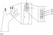
- the shaded area contains the sensor material.
- an enlargement of a finger segment according to the invention is shown, the viewing angle being along the surface normal.
- the right part of figure 1 depicts a multilayer structure of the finger segment according to the invention in cross section. This multilayer structure has a base layer (1a), a piezochromic sensor layer (1b) and a cover layer (1c).
- An anatomically shaped mold with at least one finger area can be used to manufacture the finger segment of a glove according to the invention.
- This molding tool can be supplemented with a palm area and a cuff area for manufacture as a glove.
- the mold can be designed to be variable in size.
- the mold can be made of a material suitable for dip coating and is preferably made of technical porcelain. The mold can be lowered into the respective immersion baths down to the preferred area of the mold and lifted out again after the respective dwell time.
- Salt solutions can be used as coagulation aids for separating polymers from a corresponding dispersion.
- the Layer thickness of the coating can be controlled on the one hand by the concentration of the salt solution in which the mold is first immersed, but also by the residence time in the polymer dispersion and its concentration in the subsequent immersion process step.
- the polymeric precursor in the dispersion is, for example, in the form of natural rubber or synthetic polyisoprenes and acrylonitrile-butadiene materials and combinations thereof. After being lifted out of the polymer dispersion, a polymer film of defined layer thickness has been deposited on the mold.
- the sensor material can be produced, for example, from a mixture of liquid crystal, optically active substance, network monomer, crosslinking agent and photoinitiator. This mixture independently forms a left-handed or right-handed helically ordered structure, which can also be controlled by thermal treatment.
- a preferred mixture contains the crosslinker at up to 20% by weight; Network monomer and liquid crystal up to 90% by weight, the photoinitiator up to 2% by weight and the optically active substance up to 30% by weight.
- Preferred liquid crystals are selected from the group consisting of cholesteryl benzoate, cholesterol, tolan, alkanoic acids, stilbene, azobenzenes, N-(p-ethoxy-benzylidene)-p-n-butylaniline, N-(p-methoxy-benzylidene)-p-n-butylaniline, derivatives of 4-n-alkylbenzoic acid (4-alkyl-phenyl ester), 4-phenylcinnamic acid, p-terphenyl, 1,2-bis-benzoylethene, liquid crystal mixtures of alkyl-cyanobiphenyl and alkoxycyanobiphenyl derivatives and mixtures thereof.
- optical activity can be achieved, for example, by adding 4-(4-hexyloxybenzoyloxy)benzoates or cholesteryl derivatives.
- Substances with an optically controlled radical formation mechanism are preferred as polymerization initiators over substances with a thermal radical formation behavior.
- These substances from the field of photoinitiators include, for example, benzil ketals, ⁇ -dialkoxyacetophenones, ⁇ -hydroxyalkylphenones, ⁇ -aminoalkylphenones, acylphosphine oxides or benzophenones, Irgacure 250 (BASF), Genocure LTM (Rahn) or Irgacure 2959 (SIGMA ALDRICH) .
- a preferred chiral liquid crystal phase can be obtained by mixing the components p-ethoxy(benzylidene)-p-n-butylaniline and N-(4-methoxybenzylidene)-4-butylaniline in a ratio of 3:1 if the total mixture contains the optically active substance (4- [[4-(hexyloxy)benzoyl]oxy]benzoic acid 2-octyl ester) at 30 percent by weight and is heated to over 50 °C for several minutes and then cooled.
- a preferred network-forming phase can be created by mixing methyl methacrylate with a 30% by weight mixture of 1,4-butanediol diacrylate and 1,10-decanediol diacrylate in a 1:2 ratio. 0.5% by weight of the photoinitiator Genocure LTM is added to this mixture and the mixture is then used further with the exclusion of light.
- the liquid crystalline phase and the network-forming phase are then combined and homogenized at over 50 °C for the coating processing.
- an orientation layer is first produced, which faces the sensor material.
- this layer can be produced by mechanical structuring by means of rubbing over a polyamide fiber web.
- the sensor material mixture is suitably applied to the prepared area of the overlay.
- a homogeneous layer with a uniform layer thickness can be produced in the desired area with the pad printing given here as an example.
- the phase behavior of the liquid-crystalline components can be adapted in this way by thermal treatment that a high degree of orientation is obtained in the output components of the sensor.
- the helical superstructure is stabilized by temperature and/or by chemical initiation, but ideally by light and thus by photochemical crosslinking of the reactive components.
- the mixture is irradiated with light of a wavelength distribution suitable for the photoinitiator, so that the radical formation takes place extensively. In this way, the mechanochromic sensor material is obtained.
- elastic photonic gratings can be used as sensor material. These can be produced, for example, by a process in which a lattice formed by depositing spherical silica particles on a carrier is used as a template phase. The thickness of the layer produced in this way is controlled via the process conditions of the deposition from the silica dispersion. The auxiliary grid thus obtained is dried and mechanically stabilized in a tetramethoxysilane atmosphere. The cavities between the lattice points are then filled with the monomeric components of the elastic network and photochemically polymerized to form the elastomeric network.
- ethylhexyl methacrylate is mixed with the crosslinking agent ethylene glycol dimethacrylate using the photoinitiator BAPO and reacted by irradiation with light in the range of 300 nm.
- the monofunctional monomer unit used can be replaced by lauryl, butyl and methyl derivatives, but also by butyl and hexyl acrylates, as well as mixtures of these components to adjust the mechanical responsiveness of the network.
- the composite produced in this way consisting of polymer network and auxiliary lattice, can now be brought into a desired shape.
- a washing process with a 2% strength aqueous hydrogen fluoride solution, which releases the inverse elastomer network, is preferably used to remove the silica template phase. This can be used dry and integrated in the desired area of the finger segment.
- the sensor material is preferably fully enclosed by renewed immersion in the coagulant solution and subsequent immersion in the polymer dispersion.
- the coating is then pulled off the mold so that the polymer layer previously lying on the mold points outwards and the last polymer layer produced faces the user - i.e. the finger or hand.
Description
Die vorliegende Erfindung betrifft ein Fingersegment für einen Handschuh für medizinische und diagnostische Zwecke, welches ein Sensormaterial enthält, das beim Einwirken einer mechanischen Kraft eine charakteristische Änderung erfährt, die für den Nutzer ohne technische Hilfsmittel erkennbar ist. Weiterhin betrifft die vorliegende Erfindung einen Handschuh, der dieses Fingersegment aufweist und Verwendungen des Fingersegments oder des Handschuhs.The present invention relates to a finger segment for a glove for medical and diagnostic purposes, which contains a sensor material which, when subjected to a mechanical force, undergoes a characteristic change which can be recognized by the user without technical aids. Furthermore, the present invention relates to a glove that has this finger segment and uses of the finger segment or the glove.
Medizinische Handschuhe bzw. Fingersegmente für diese Handschuhe kommen in nahezu allen medizinischen Versorgungssituationen zum Einsatz und dienen der Vermeidung eines direkten Kontakts zwischen Patient und Anwender. Sie bestehen aus einem Polymermaterial und sind für den einmaligen Gebrauch vorgesehen. Diese Handschuhe werden in sterilen und nichtsterilen Varianten hergestellt und gehören zur persönlichen Schutzausrüstung von Medizinern und Pflegepersonal. Durch eine anschmiegsame Passform wird ein hoher Tragekomfort aber auch eine unbeeinträchtigte haptische Wahrnehmung gewährleistet. Diagnostische und therapeutische Aufgaben können mit diesen Handschuhen leicht durchgeführt werden.Medical gloves or finger segments for these gloves are used in almost all medical care situations and serve to avoid direct contact between the patient and the user. They are made of a polymer material and are intended for single use. These gloves are manufactured in sterile and non-sterile versions and are part of the personal protective equipment for medical and nursing staff. A snug fit ensures high wearing comfort but also an unimpaired haptic perception guaranteed. Diagnostic and therapeutic tasks can be easily performed with these gloves.
Neben den Grundanforderungen an einen medizinischen Handschuh ist für besondere medizinische Aufgaben die Integration zusätzlicher Funktionen vorteilhaft. Insbesondere bedeutsam ist die Integration von zusätzlichen Funktionen in einen medizinischen Handschuh für die Herstellung einer chirurgischen Naht.In addition to the basic requirements for a medical glove, the integration of additional functions is advantageous for special medical tasks. The integration of additional functions in a medical glove for the production of a surgical seam is particularly important.
Zum Verschließen und Fixieren einer Operationswunde erstellt der Operateur eine chirurgische Naht. Dabei werden zunächst die Wundränder durch das Nahtmaterial miteinander verbunden. Durch einen Zug am Nahtmaterial wird ein direkter Kontakt der Ränder hergestellt, ohne dass angrenzendes Gewebe geschädigt wird. Anschließend wird die Naht mit einem chirurgischen Knoten fixiert. Der Vorgang erfordert einen präzisen Krafteinsatz durch den Operateur. Hierbei wird das Nahmaterial über einen Finger geleitet, der die Zugkraft auf Naht und Knoten überträgt. Dabei übt der Faden einen Druck auf seine Auflagefläche aus. Dieser Druck ist somit ein Maß für die geleistete Zugkraft. Die erforderlichen Zugkräfte und resultierenden Auflagedrücke variieren mit den zu vernähenden Gewebearten. Der Operateur ist bei der Dosierung der Kraft rein auf Erfahrungswerte angewiesen. Insbesondere Anfängern fällt es sehr schwer die benötigte Kraft abzuschätzen. Derzeit gibt es keine technischen Hilfsmittel, die für die Unterstützung in geeigneter Weise eingesetzt werden können.To close and fix a surgical wound, the surgeon creates a surgical suture. The edges of the wound are first connected to one another with the suture material. By pulling on the suture material, direct contact is made between the edges without damaging adjacent tissue. The suture is then secured with a surgical knot. The process requires a precise use of force by the surgeon. The suture material is guided over a finger, which transmits the tensile force to the suture and knot. The thread exerts pressure on its contact surface. This pressure is therefore a measure of the tensile force that is exerted. The required tensile forces and resulting contact pressures vary with the type of fabric to be sewn. When dosing the force, the surgeon relies purely on empirical values. Especially beginners find it very difficult to estimate the required force. There are currently no technical tools that can be used appropriately to provide support.
Die vorliegende Erfindung zielt auf Anwendungsszenarien, insbesondere im Medizinbereich, ab, bei denen es erforderlich ist, mit der Hand oder mit den Fingern ausgeübte Kräfte genau zu dosieren. Anwendungsfelder liegen neben der Chirurgie beispielsweise in der Aus- und Fortbildung von Medizinern und therapeutischem Personal.The present invention is aimed at application scenarios, in particular in the medical field, in which it is necessary to meter forces exerted by hand or fingers precisely. In addition to surgery, fields of application are, for example, in the training and further education of physicians and therapeutic staff.
Medizinische Handschuhe ohne zusätzliche Funktionen sind im Stand der Technik beschrieben.Medical gloves without additional functions are described in the prior art.
Die Integration zusätzlicher Funktionen in ein Handschuhsystem ist ebenso bekannt.The integration of additional functions into a glove system is also known.
Eine Funktionalisierung von Handschuhen bzw. Fingersegmenten, die es dem Nutzer erlaubt, die mit der Hand bzw. den Fingern ausgeübte mechanische Kraft zu dosieren, ist bislang nicht beschrieben worden.A functionalization of gloves or finger segments that allows the user to use the mechanical force exerted with the hand or fingers Dosing force has not yet been described.
Ausgehend davon bestand die Aufgabe der vorliegenden Erfindung darin, ein Fingersegment für einen Handschuh bereitzustellen, welches es dem Nutzer ermöglicht die ausgeübte Kraft möglichst exakt zu dosieren, ohne dass er hierzu technische Hilfsmittel benötigt.Proceeding from this, the object of the present invention was to provide a finger segment for a glove which allows the user to meter the force exerted as precisely as possible without requiring technical aids for this purpose.
Diese Aufgabe wird durch das Fingersegment für einen Handschuh für diagnostische und medizinische Zwecke mit den Merkmalen von Anspruch 1 gelöst. Dieses Fingersegment enthält ein den Finger des Nutzers umschließendes, elastisches Material und ein vom elastischen Material eingeschlossenes Sensormaterial, wobei das Sensormaterial geeignet ist, eine einwirkende mechanische Kraft anzuzeigen und wobei das Sensormaterial eine für die einwirkende mechanische Kraft charakteristische Änderung erfährt, die für den Nutzer ohne technische Hilfsmittel erkennbar ist. Das Fingersegment ist dadurch gekennzeichnet, dass das Sensormaterial dazu geeignet ist, mechanische Kräfte im Bereich von 1 bis 25 N, die auf das Sensormaterial in unterschiedlichen Auftreffwinkeln wirken, zu visualisieren.This object is solved by the finger segment for a glove for diagnostic and medical purposes with the features of claim 1. This finger segment contains an elastic material enclosing the user's finger and a sensor material enclosed by the elastic material, the sensor material being suitable for displaying an acting mechanical force and the sensor material undergoing a change that is characteristic of the acting mechanical force and which the user does not notice without technical aids can be identified. The finger segment is characterized in that the sensor material is suitable for visualizing mechanical forces in the range from 1 to 25 N, which act on the sensor material at different impact angles.
Vorteilhafte Eigenschaften des erfindungsgemäßen Fingersegments werden in den abhängigen Ansprüchen 2 bis 13 angegeben.Advantageous properties of the finger segment according to the invention are specified in the dependent claims 2-13.
Anspruch 14 betrifft einen Handschuh der mindestens ein Fingersegment gemäß einem der Ansprüche 1 bis 13 aufweist.Claim 14 relates to a glove which has at least one finger segment according to one of claims 1 to 13.
Weiterhin betrifft Anspruch 15 Verwendungen des Fingersegments nach einem der Ansprüche 1 bis 13 oder des Handschuhs gemäß Anspruch 14.Furthermore, claim 15 relates to uses of the finger segment according to one of claims 1 to 13 or of the glove according to claim 14.
Ein "Fingersegment" eines Handschuhs meint im Sinne der vorliegenden Erfindung den Fingerbereich eines Handschuhs, der geeignet ist den Finger des Nutzers vollständig zu umschließen. Der Begriff "umschließen" meint dabei, ein vollständiges und enganliegendes umhüllen des Fingers, wobei der Finger abgebildet wird, ohne dass es zu einer Beeinträchtigung des Trägers kommt.In the context of the present invention, a “finger segment” of a glove means the finger area of a glove that is suitable for completely enclosing the user's finger. The term “enclose” here means a complete and tight-fitting enveloping of the finger, with the finger being imaged without the wearer being adversely affected.
Im Folgenden werden bevorzugte Ausführungsformen des erfindungsgemä-ßen Fingersegments angegeben. Die vorliegende Erfindung eines Fingersegments wird im Hauptanspruch 1 definiert. Hauptanspruch 16 definiert die Verwendung dieses Fingersegments. Die weiteren Ausführungsformen werden in den Nebenansprüchen definiert.Preferred embodiments of the finger segment according to the invention are specified below. The present invention of a finger segment is defined in independent claim 1. Main claim 16 defines the use of this finger segment. The further embodiments are defined in the dependent claims.
Gemäß einer bevorzugten Ausführungsform des erfindungsgemäßen Fingersegments ist das elastische Material ausgewählt aus der Gruppe bestehend aus transluzenten Latexmaterialien, insbesondere Nitrilkautschuken, Gummimaterialien, Kunststoffmaterialien, insbesondere Polyvinylchlorid, Polyethylen, Neopren, Styren-Butadien-Polymeren und Mischungen hiervon.According to a preferred embodiment of the finger segment according to the invention, the elastic material is selected from the group consisting of translucent latex materials, in particular nitrile rubbers, rubber materials, plastic materials, in particular polyvinyl chloride, polyethylene, neoprene, styrene-butadiene polymers and mixtures thereof.
Eine andere erfindungsgemäße bevorzugte Ausführungsform sieht vor, dass das Fingersegment zumindest teilweise und bevorzugt vollständig einen mehrschichtigen Aufbau aufweist, wobei ein dreischichtiger Aufbau besonders bevorzugt ist und insbesondere bevorzugt eine innere Schicht, die das Sensormaterial enthält von zwei äußeren Schichten, die das elastische Material enthalten, eingeschlossen ist. Dabei beträgt die Schichtdicke der Schicht mit dem Sensormaterial bevorzugt von 50 bis 100 µm und besonders bevorzugt von 50 bis 60 µm und die Gesamtdicke des Mehrschichtaufbaus bevorzugt von 150 bis 1000 µm und besonders bevorzugt von 150 bis 500 µm.Another preferred embodiment according to the invention provides that the finger segment at least partially and preferably completely has a multi-layer structure, with a three-layer structure being particularly preferred and particularly preferred an inner layer containing the sensor material and two outer layers containing the elastic material. is included. The layer thickness of the layer with the sensor material is preferably from 50 to 100 μm and particularly preferably from 50 to 60 μm and the total thickness of the multilayer structure is preferably from 150 to 1000 μm and particularly preferably from 150 to 500 μm.
Eine andere bevorzugte Ausführungsform des erfindungsgemäßen Fingersegments sieht vor, dass das elastische Material den Finger des Nutzers vollständig umschließt.Another preferred embodiment of the finger segment according to the invention provides that the elastic material completely encloses the user's finger.
Gemäß einer weiteren bevorzugten Ausführungsform der vorliegenden Erfindung besteht das Fingersegment aus dem elastischen Material und dem Sensormaterial.According to a further preferred embodiment of the present invention, the finger segment consists of the elastic material and the sensor material.
Nach einer anderen bevorzugten Ausführungsform vorliegender Erfindung wird das Sensormaterial durch ein Verfahren ausgewählt aus der Gruppe bestehend aus Rakeln, Tauchen, Sprühen, Drucken und Kleben auf dem elastischen Material als Schicht auf einer Schicht des elastischen Materials fixiert, wobei es bei Rakeln, Tauchen, Sprühen und Drucken bevorzugt ist, dass das Sensormaterial vollständig vom elastischen Material umhüllt wird.According to another preferred embodiment of the present invention, the sensor material is fixed by a method selected from the group consisting of squeegeeing, dipping, spraying, printing and gluing on the elastic material as a layer on a layer of the elastic material, with squeegeeing, dipping, spraying and printing it is preferred that the sensor material is completely encased by the elastic material.
Eine andere bevorzugte Ausführungsform der vorliegenden Erfindung sieht vor, dass das Sensormaterial in allen Bereichen des Fingerelements eine identische Empfindlichkeit aufweist.Another preferred embodiment of the present invention provides that the sensor material is identical in all areas of the finger element has sensitivity.
Gemäß einer weiteren bevorzugten Ausführungsform vorliegender Erfindung ist das Sensormaterial in verschiedenen Bereichen des Fingerelements angebracht und weist jeweils unterschiedliche Empfindlichkeiten auf, wobei die Differenz in der Empfindlichkeit mindestens 5 N, bevorzugt mindestens 8 N beträgt. Dabei ist es bevorzugt, dass die Einstellung der Empfindlichkeit des Sensormaterials während des Herstellprozesses erfolgt, besonders bevorzugt erfolgt die Einstellung der Empfindlichkeit durch Materialwahl des Sensormaterials und/oder durch die Einstellung der Schichtdicke.According to a further preferred embodiment of the present invention, the sensor material is attached in different areas of the finger element and has different sensitivities in each case, the difference in sensitivity being at least 5N, preferably at least 8N. In this case, it is preferred that the sensitivity of the sensor material is adjusted during the production process; the sensitivity is particularly preferably adjusted by selecting the material for the sensor material and/or by adjusting the layer thickness.
Nach einer weiteren bevorzugten Ausführungsform der vorliegenden Erfindung ist die charakteristische Änderung des Sensormaterials durch die Einwirkung von mechanischer Kraft eine Farbänderung im sichtbaren Bereich des elektromagnetischen Spektrums und kann reversibel oder irreversibel erfolgen, wobei ein reversibler Farbwechsel bevorzugt ist. Dabei ist es bevorzugt, dass die Farbänderung im sichtbaren Bereich des elektromagnetischen Spektrums nur durch einen zusätzlichen Stimulus ausgelöst wird, bevorzugt ist dieser zusätzliche Stimulus die Einwirkung von Licht einer Wellenlänger von < 400 nm, bevorzugt < 360 nm, insbesondere im Bereich von 280 bis 400 nm und besonders bevorzugt im Bereich von 280 bis 360 nm.According to a further preferred embodiment of the present invention, the characteristic change in the sensor material due to the action of mechanical force is a color change in the visible range of the electromagnetic spectrum and can be reversible or irreversible, with a reversible color change being preferred. It is preferred that the color change in the visible range of the electromagnetic spectrum is only triggered by an additional stimulus, preferably this additional stimulus is the effect of light with a wavelength of <400 nm, preferably <360 nm, in particular in the range from 280 to 400 nm and particularly preferably in the range from 280 to 360 nm.
Nach einer anderen bevorzugten Ausführungsform der vorliegenden Erfindung ist das Sensormaterial ein Material, welches herstellbar aus einem Gemisch aus einem Flüssigkristall, einer optisch aktiven Substanz, einem Photoinitiator einem Netzwerkmonomer und einem Vernetzer ist. Dabei ist der Flüssigkristall bevorzugt ausgewählt aus der Gruppe bestehend aus Benzoesäurecholesterylester, Cholesterin, Tolan, Alkansäuren, Stilben, Azobenzolen, N-(p-Ethoxy-benzyliden)-p-n-butylanilin, N-(p-Methoxy-benzyliden)-p-n-butylanilin, Derivaten des 4-n-Alkylbenzoesäure-(4-alkyl-phenylesters), 4-Phenylzimtsäure, p-Terphenyl, 1,2-Bis-benzoylethen, Flüssigkristallmischungen von Alkylcyanobiphenyl- und Alkoxycyanobiphenyl-derivaten und Mischungen hiervon. Die optische aktive Substanz ist bevorzugt ein 4-(4-Hexyloxybenzoyloxy)benzoat oder ein Cholesterylderivate. Die netzwerkbildenden Monomere sind bevorzugt Verbindungen ausgewählt aus der Gruppe bestehend aus Benzylmethacrylat, 2-Ethylhexylacrylat, 2-Methoxyethylacrylat, Octadecylacrylat, Reaktivmesogenen und Mischungen hiervon.According to another preferred embodiment of the present invention, the sensor material is a material that can be produced from a mixture of a liquid crystal, an optically active substance, a photoinitiator, a network monomer and a crosslinker. The liquid crystal is preferably selected from the group consisting of cholesteryl benzoate, cholesterol, tolan, alkanoic acids, stilbene, azobenzenes, N-(p-ethoxy-benzylidene)-pn-butylaniline, N-(p-methoxy-benzylidene)-pn-butylaniline , derivatives of 4-n-alkylbenzoic acid (4-alkyl-phenyl ester), 4-phenylcinnamic acid, p-terphenyl, 1,2-bis-benzoylethene, liquid crystal mixtures of alkylcyanobiphenyl and alkoxycyanobiphenyl derivatives and mixtures thereof. The optically active substance is preferably a 4-(4-hexyloxybenzoyloxy)benzoate or a cholesteryl derivative. The network-forming monomers are preferably compounds selected from the group consisting of benzyl methacrylate, 2-ethylhexyl acrylate, 2-methoxyethyl acrylate, octadecyl acrylate, reactive mesogens and mixtures thereof.
Der Vernetzer ist bevorzugt ausgewählt aus der Gruppe bestehend aus 1,4-Butandiol-diacrylat, Polyethylenglycol-diacrylat, 1,10-Decandioldiacrylat und Mischungen hiervon. Der Photoinitator ist bevorzugt ausgewählt aus der Gruppe bestehend aus Benzilketalen, α-Dialkoxyacetophenonen, α-Hydroxyalkylphenolen, α-Aminoalkylphenonen, Acylphosphinoxiden, Benzophenonen, Photosäuren und Mischungen hiervon.The crosslinker is preferably selected from the group consisting of 1,4-butanediol diacrylate, polyethylene glycol diacrylate, 1,10-decanediol diacrylate and mixtures thereof. The photoinitiator is preferably selected from the group consisting of benzil ketals, α-dialkoxyacetophenones, α-hydroxyalkyl phenols, α-aminoalkyl phenones, acylphosphine oxides, benzophenones, photoacids and mixtures thereof.
Bevorzugte Photoinitatoren sind Irgacure 250 (BASF), Genocure LTM (Rahn) und Irgacure 2959 (Sigma Aldrich).Preferred photoinitiators are Irgacure 250 (BASF), Genocure LTM (Rahn) and Irgacure 2959 (Sigma Aldrich).
Die Herstellung geeigneter Photomaterialien wurde in der Literatur beschrieben. So beispielsweise von
Dabei ist es besonders bevorzugt, dass ein Gemisch verwendet wird, welches den Vernetzer mit bis zu 20 Gew.-%; das netzwerkbildende Monomer und den Flüssigkristall mit bis zu 90 Gew.-%, den Photoinitiator mit bis zu 2 Gew.-% und die optisch aktive Substanz mit bis zu 30 Gew.-% enthält.It is particularly preferred that a mixture is used which contains the crosslinker with up to 20% by weight; the network-forming monomer and the liquid crystal up to 90% by weight, the photoinitiator up to 2% by weight and the optically active substance up to 30% by weight.
Gemäß einer weiteren bevorzugten Ausführung vorliegender Erfindung ist die charakteristische Änderung die das Sensormaterial erfährt für Maschinen lesbar und/oder auswertbar. Eine besonders bevorzugte charakteristische Änderung ist hierbei ein Farbwechsel.According to a further preferred embodiment of the present invention, the characteristic change which the sensor material undergoes can be read and/or evaluated by machines. A particularly preferred characteristic change here is a color change.
Erfindungsgemäß kann das Sensormaterial mechanische Kräfte im Bereich von 1 bis 25 N und bevorzugt von 5 bis 10 N visualisieren, die auf das Sensormaterial oder die das Sensormaterial enthaltende Schicht in unterschiedlichen Auftreffwinkeln wirken. Die dabei senkrecht auf die Sensorschicht wirkenden Kräfte leiten sich aus der Summe aller wirkenden Kräfte ab. Für den Einsatz an parenchymatösem Gewebe, insbesondere an Leber- und Darmgewebe ist eine Visualisierung von Kräften im Bereich von 3 bis 10 N bevorzugt und besonders bevorzugt 4 N. Für Muskelgewebe ist eine Visualisierung von Kräften im Bereich von 10 bis 21 N bevorzugt und besonders bevorzugt von 10 bis 12 N.According to the invention, the sensor material can visualize mechanical forces in the range from 1 to 25 N and preferably from 5 to 10 N, which act on the sensor material or the layer containing the sensor material at different angles of incidence. The forces acting vertically on the sensor layer are derived from the sum of all acting forces. For use on parenchymatous tissue, in particular on liver and intestinal tissue, visualization of forces in the range from 3 to 10 N is preferred and particularly preferably 4 N. Visualization of forces in the range from 10 to 21 N is preferred and particularly preferred for muscle tissue preferably from 10 to 12 N.
Nach einer anderen bevorzugten Ausführungsform der vorliegenden Erfindung kann das Sensormaterial Drücke im Bereich von 0,1 bis 5 bar und bevorzugt von 0,5 bis 2,5 bar visualisieren, die senkrecht zur Flächennormalen des Sensormaterials oder der das Sensormaterial enthaltenden Schicht wirken.According to another preferred embodiment of the present invention, the sensor material can visualize pressures in the range from 0.1 to 5 bar and preferably from 0.5 to 2.5 bar, which act perpendicular to the surface normal of the sensor material or the layer containing the sensor material.
Eine weitere bevorzugte erfindungsgemäße Ausführungsform sieht vor, dass das Fingersegment geeignet ist
- a) anzuzeigen ob eine mechanische Krafteinwirkung erfolgte; und
- b) diese Krafteinwirkung zu quantifizieren.
- a) indicate whether a mechanical force was applied; and
- b) to quantify this force effect.
Nach einer anderen bevorzugten Ausführungsform der vorliegenden Erfindung wird die Intensität der mechanischen Krafteinwirkung durch unterschiedliche Farben visualisiert, wobei es besonders bevorzugt ist, dass eine zunehmende Einwirkung der mechanischen Kraft durch eine Blauverschiebung angezeigt wird.According to another preferred embodiment of the present invention, the intensity of the mechanical force effect is visualized by different colors, it being particularly preferred that an increasing mechanical force effect is indicated by a blue shift.
Eine weitere erfindungsgemäße Ausführungsform sieht vor, dass die charakteristische Änderung des Sensormaterials auch in den an die Bereiche in denen mechanische Krafteinwirkung erfolgte direkt benachbarten Bereichen angezeigt wird, besonders bevorzugt durch einen Farbumschlag.A further embodiment according to the invention provides that the characteristic change of the sensor material is also displayed in the areas directly adjacent to the areas in which mechanical force was applied, particularly preferably by a color change.
Nach einer anderen erfindungsgemäßen Ausführungsform erfüllt das Fingersegment die Erfordernisse der Europäischen Richtlinie 93/42/EWG und/oder der Europäischen Norm EN 455-1 bis 4.According to another embodiment of the invention, the finger segment meets the requirements of European Directive 93/42/EEC and/or European Standard EN 455-1 to 4.
Gemäß einer weiteren Ausführungsform der vorliegenden Erfindung ist das Fingersegment als Fingerling ausgebildet.According to a further embodiment of the present invention, the finger segment is designed as a fingerstall.
Die vorliegende Erfindung betrifft auch einen Handschuh der zumindest ein erfindungsgemäßes Fingersegment umfasst.The present invention also relates to a glove which comprises at least one finger segment according to the invention.
Dabei sind bevorzugtermaßen auch die übrigen Teile des Handschuhs steril und erfüllen besonders bevorzugt die Erfordernisse der Europäischen Richtlinie 93/42/EWG und/oder der Europäischen Norm EN 455-1 bis 4.The remaining parts of the glove are preferably also sterile and particularly preferably meet the requirements of European Directive 93/42/EEC and/or European Standard EN 455-1 to 4.
Die vorliegende Erfindung betrifft auch die Verwendung des erfindungsgemä-ßen Fingersegments oder des erfindungsgemäßen Handschuhs in der Ausbildung von Medizinern, im Bereich der Chirurgie, insbesondere der Thorax-, Gefäß-, Viszeral- und Neurochirurgie, Orthopädie, Frauenheilkunde, Zahnheilkunde, Physiotherapie, Feinmechanik und bei der CD-Herstellung.The present invention also relates to the use of the finger segment according to the invention or the glove according to the invention in the training of medical professionals, in the field of surgery, in particular thoracic, vascular, visceral and neurosurgery, orthopaedics, gynecology, dentistry, physiotherapy, precision engineering and in CD production.
Im linken Teil von
Anhand der nachfolgenden allgemeinen Herstellvorschrift soll der erfindungsgemäße Gegenstand näher erläutert werden, ohne diesen auf die hier gezeigten spezifischen Ausführungsformen einschränken zu wollen.The subject according to the invention is to be explained in more detail on the basis of the following general production specification, without wishing to restrict it to the specific embodiments shown here.
Für die Fertigung des erfindungsgemäßen Fingersegments eines Handschuhs kann ein anatomisch geformtes Formwerkzeug mit zumindest einem Fingerbereich genutzt werden. Für die Ausfertigung als Handschuh kann dieses Formwerkzeug um einen Handflächenbereich und einen Stulpenbereich ergänzt werden. Zur Erzeugung unterschiedlicher Passgrößen ist es möglich das Formwerkzeug in seiner Größe variabel auszuführen. Das Formwerkzeug kann aus einem für Tauchbeschichtungen geeigneten Material gefertigt werden und besteht bevorzugt aus technischem Porzellan. Die Form kann bis in den bevorzugten Bereich des Formwerkzeugs in die jeweiligen Tauchbäder abgesenkt werden und nach der jeweiligen Verweildauer wieder herausgehoben werden.An anatomically shaped mold with at least one finger area can be used to manufacture the finger segment of a glove according to the invention. This molding tool can be supplemented with a palm area and a cuff area for manufacture as a glove. In order to produce different fitting sizes, it is possible to design the mold to be variable in size. The mold can be made of a material suitable for dip coating and is preferably made of technical porcelain. The mold can be lowered into the respective immersion baths down to the preferred area of the mold and lifted out again after the respective dwell time.
Als Koagulationshilfsmittel zur Abscheidung von Polymeren aus einer entsprechenden Dispersion können Salzlösungen eingesetzt werden. Die Schichtdicke des Überzuges kann einerseits durch die Konzentration der Salzlösung, in die das Formwerkzeug zunächst getaucht wird, gesteuert werden, aber auch durch die Verweildauer in der Polymerdispersion und deren Konzentration im sich anschließenden Tauchprozessschritt. Der polymere Vorläufer in der Dispersion liegt beispielsweise in Form von natürlichem Kautschuk oder von synthetischen Polyisoprenen und Acrylonitril-Butadienmaterialien und deren Kombinationen vor. Nach Herausheben aus der Polymerdispersion hat sich ein Polymerfilm definierter Schichtdicke auf dem Formwerkzeug abgeschieden.Salt solutions can be used as coagulation aids for separating polymers from a corresponding dispersion. The Layer thickness of the coating can be controlled on the one hand by the concentration of the salt solution in which the mold is first immersed, but also by the residence time in the polymer dispersion and its concentration in the subsequent immersion process step. The polymeric precursor in the dispersion is, for example, in the form of natural rubber or synthetic polyisoprenes and acrylonitrile-butadiene materials and combinations thereof. After being lifted out of the polymer dispersion, a polymer film of defined layer thickness has been deposited on the mold.
Das Sensormaterial kann beispielsweise aus einem Gemisch aus Flüssigkristall, optisch aktiver Substanz, Netzwerkmonomer, Vernetzer und Photoinitiator hergestellt werden. Dieses Gemisch bildet eigenständig eine linksgängig oder rechtsgängig helikal geordnete Struktur aus, die durch thermische Behandlung zusätzlich gesteuert werden kann.The sensor material can be produced, for example, from a mixture of liquid crystal, optically active substance, network monomer, crosslinking agent and photoinitiator. This mixture independently forms a left-handed or right-handed helically ordered structure, which can also be controlled by thermal treatment.
Die nachfolgende Aufstellung ist nur als Auswahl an Substanzen zu verstehen. Dabei ist für die Sensorfunktion maßgeblich das molekulare Verhältnis der Komponenten zueinander von Bedeutung. Ein bevorzugtes Gemisch enthält den Vernetzer mit bis zu 20 Gew.-%; Netzwerkmonomer und Flüssigkristall mit bis zu 90 Gew.-%, den Photoinitiator mit bis zu 2 Gew.-% und die optisch aktive Substanz mit bis zu 30 Gew.-%.The following list is only to be understood as a selection of substances. The molecular ratio of the components to one another is decisive for the sensor function. A preferred mixture contains the crosslinker at up to 20% by weight; Network monomer and liquid crystal up to 90% by weight, the photoinitiator up to 2% by weight and the optically active substance up to 30% by weight.
Bevorzugte Flüssigkristalle sind ausgewählt aus der Gruppe bestehend aus Benzoesäurecholesterylester, Cholesterin, Tolan, Alkansäuren, Stilben, Azobenzolen, N-(p-Ethoxy-benzyliden)-p-n-butylanilin, N-(p-Methoxy-benzyliden)-p-n-butylanilin, Derivaten des 4-n-Alkylbenzoesäure-(4-alkyl-phenylesters), 4-Phenylzimtsäure, p-Terphenyl, 1,2-Bis-benzoylethen, Flüssigkristallmischungen von Alkyl-cyanobiphenyl- und Alkoxycyanobiphenylderivaten und Mischungen hiervon.Preferred liquid crystals are selected from the group consisting of cholesteryl benzoate, cholesterol, tolan, alkanoic acids, stilbene, azobenzenes, N-(p-ethoxy-benzylidene)-p-n-butylaniline, N-(p-methoxy-benzylidene)-p-n-butylaniline, derivatives of 4-n-alkylbenzoic acid (4-alkyl-phenyl ester), 4-phenylcinnamic acid, p-terphenyl, 1,2-bis-benzoylethene, liquid crystal mixtures of alkyl-cyanobiphenyl and alkoxycyanobiphenyl derivatives and mixtures thereof.
Die optische Aktivität kann beispielsweise durch den Zusatz von 4-(4-Hexyloxybenzoyloxy)benzoaten oder Cholesterylderivaten erzielt werden.The optical activity can be achieved, for example, by adding 4-(4-hexyloxybenzoyloxy)benzoates or cholesteryl derivatives.
Als netzwerkbildende Monomere werden bevorzugt Verbindungen ausgewählt aus der Gruppe bestehend aus Benzylmethacrylat, 2-Ethylhexylacrylat, 2-Methoxyethylacrylat, Octadecylacrylat, Reaktivmesogenen und Mischungen hiervon eingesetzt.Compounds selected from the group consisting of benzyl methacrylate, 2-ethylhexyl acrylate, 2-methoxyethyl acrylate, octadecyl acrylate, reactive mesogens and mixtures thereof are preferably used as network-forming monomers.
Als Vernetzer kommen bevorzugt Verbindungen ausgewählt aus der Gruppe bestehend aus 1,4-Butandiol-diacrylat, Polyethylenglycol-diacrylat, 1,10-Decandioldiacrylat und Mischungen hiervon zum Einsatz.Compounds selected from the group consisting of 1,4-butanediol diacrylate, polyethylene glycol diacrylate, 1,10-decanediol diacrylate and mixtures thereof are preferably used as crosslinkers.
Als Polymerisationsinitiatoren sind Substanzen mit einem optischen gesteuerten Radikalbildungsmechanismus gegenüber den Substanzen mit einem thermischen Radikalbildungsverhalten bevorzugt. Diese Substanzen aus dem Bereich der Photoinitiatoren umfassen beispielsweise Benzil Ketale, α-Dialkoxyacetophenone, α-Hydroxy-alkylphenone, α-Amino-alkylphenone, Acylphosphinoxide oder Benzophenone, Irgacure 250 (BASF), Genocure LTM (Rahn) oder Irgacure 2959 (SIGMA ALDRICH).Substances with an optically controlled radical formation mechanism are preferred as polymerization initiators over substances with a thermal radical formation behavior. These substances from the field of photoinitiators include, for example, benzil ketals, α-dialkoxyacetophenones, α-hydroxyalkylphenones, α-aminoalkylphenones, acylphosphine oxides or benzophenones, Irgacure 250 (BASF), Genocure LTM (Rahn) or Irgacure 2959 (SIGMA ALDRICH) .
Eine bevorzugte chirale Flüssigkristallphase kann durch das Mischen der Komponenten p-Ethoxy(benzyliden)-p-n-butylanilin und N-(4-Methoxybenzyliden)-4-butylanilin im Verhältnis 3 : 1 erhalten werden, wenn die Gesamtmischung die optisch aktive Substanz (4-[[4-(Hexyloxy)benzoyl]oxy]benzoesäure-2-octylester) mit 30 Gewichtsprozent enthält und für mehrere Minuten auf über 50 °C erhitzt und anschließend abgekühlt wird.A preferred chiral liquid crystal phase can be obtained by mixing the components p-ethoxy(benzylidene)-p-n-butylaniline and N-(4-methoxybenzylidene)-4-butylaniline in a ratio of 3:1 if the total mixture contains the optically active substance (4- [[4-(hexyloxy)benzoyl]oxy]benzoic acid 2-octyl ester) at 30 percent by weight and is heated to over 50 °C for several minutes and then cooled.
Eine bevorzugte netzwerkbildende Phase kann durch Mischen von Methylmethacrylat mit einer 30 Gew.-%igen Mischung von 1,4-Butandiol-diacrylat und 1,10-Decandioldiacrylat im Verhältnis 1 : 2 erzeugt werden. Dieser Mischung werden 0,5 Gew.-% des Photoinitiators Genocure LTM beigemischt und anschließend wird die Mischung unter Lichtausschluss weiterverwendet. Die flüssigkristalline Phase und die netzwerkbildende Phase werden daraufhin vereinigt und für das Beschichtungsprocessing bei über 50 °C homogenisiert.A preferred network-forming phase can be created by mixing methyl methacrylate with a 30% by weight mixture of 1,4-butanediol diacrylate and 1,10-decanediol diacrylate in a 1:2 ratio. 0.5% by weight of the photoinitiator Genocure LTM is added to this mixture and the mixture is then used further with the exclusion of light. The liquid crystalline phase and the network-forming phase are then combined and homogenized at over 50 °C for the coating processing.
Im dafür vorgesehen Bereich des Überzugs wird zunächst eine Orientierungsschicht hergestellt, die dem Sensormaterial zugewandt ist. Die Herstellung dieser Schicht kann im einfachsten Fall durch mechanische Strukturierung mittels Reiben über einen Polyamidfaserflor erfolgen.In the area of the coating provided for this purpose, an orientation layer is first produced, which faces the sensor material. In the simplest case, this layer can be produced by mechanical structuring by means of rubbing over a polyamide fiber web.
Die Sensormaterialmischung wird in geeigneter Weise auf den vorbereiteten Bereich des Überzugs aufgetragen. Durch den hier exemplarisch angeführten Tampondruck kann eine homogene Schicht mit einheitlicher Schichtdicke im gewünschten Bereich erzeugt werden. Durch thermische Behandlung kann das Phasenverhalten der flüssigkristallinen Komponenten derart angepasst werden, dass ein hoher Grad an Orientierung in den Ausgangskomponenten des Sensors erhalten wird.The sensor material mixture is suitably applied to the prepared area of the overlay. A homogeneous layer with a uniform layer thickness can be produced in the desired area with the pad printing given here as an example. The phase behavior of the liquid-crystalline components can be adapted in this way by thermal treatment that a high degree of orientation is obtained in the output components of the sensor.
Durch Temperatur und/oder durch chemische Initiierung, jedoch idealerweise durch Licht und damit durch photochemische Vernetzung der reaktiven Komponenten, erfolgt die Stabilisierung der helikalen Überstruktur. Hierfür wird das Gemisch mit Licht einer für den Photoinitiator geeigneten Wellenlängenverteilung bestrahlt, sodass die Radikalbildung umfänglich stattfindet. Hierdurch wird das mechanochrome Sensormaterial erhalten.The helical superstructure is stabilized by temperature and/or by chemical initiation, but ideally by light and thus by photochemical crosslinking of the reactive components. For this purpose, the mixture is irradiated with light of a wavelength distribution suitable for the photoinitiator, so that the radical formation takes place extensively. In this way, the mechanochromic sensor material is obtained.
Alternativ können elastische photonische Gitter als Sensormaterial eingesetzt werden. Diese lassen sich beispielsweise durch einen Prozess erzeugen, bei dem ein durch Abscheidung von sphärischen Silikapartikeln auf einem Träger gebildete Gitter als Templatphase genutzt werden. Die Dicke der auf diesem Wege erzeugten Schicht ist über die Prozessbedingungen der Abscheidung aus der Silikadispersion gesteuert. Das auf diese Weise erhaltene Hilfsgitter wird getrocknet und in einer Tetramethoxysilanatmosphäre mechanisch stabilisiert. Im Anschluss werden die Hohlräume zwischen den Gitterpunkten mit den monomeren Bestandteilen des elastischen Netzwerkes gefüllt und photochemisch zum elastomeren Netzwerk polymerisiert. Dabei werden bevorzugt im Verhältnis von 10 : 1 : 0,05 Ethylhexylmethacrylat mit dem Vernetzer Ethylenglykoldimethacrylat unter Verwendung des Photoinitiators BAPO gemischt und durch Bestrahlung mit Licht im Bereich von 300 nm zur Reaktion gebracht. Die genutzte monofunktionale Monomereinheit kann durch Lauryl-, Butyl- und Methylderivate, aber auch durch Butyl- und Hexylacrylate, sowie Mischungen dieser Komponenten zur Einstellung der mechanischen Responsivität des Netzwerkes ersetzt werden. Das auf diese Weise erzeugte Komposit bestehend aus Polymernetzwerk und Hilfsgitter kann nun in eine gewünschte Form gebracht werden.Alternatively, elastic photonic gratings can be used as sensor material. These can be produced, for example, by a process in which a lattice formed by depositing spherical silica particles on a carrier is used as a template phase. The thickness of the layer produced in this way is controlled via the process conditions of the deposition from the silica dispersion. The auxiliary grid thus obtained is dried and mechanically stabilized in a tetramethoxysilane atmosphere. The cavities between the lattice points are then filled with the monomeric components of the elastic network and photochemically polymerized to form the elastomeric network. Here, preferably in a ratio of 10:1:0.05, ethylhexyl methacrylate is mixed with the crosslinking agent ethylene glycol dimethacrylate using the photoinitiator BAPO and reacted by irradiation with light in the range of 300 nm. The monofunctional monomer unit used can be replaced by lauryl, butyl and methyl derivatives, but also by butyl and hexyl acrylates, as well as mixtures of these components to adjust the mechanical responsiveness of the network. The composite produced in this way, consisting of polymer network and auxiliary lattice, can now be brought into a desired shape.
Zur Entfernung der Silika-Templathase dient bevorzugt ein Waschprozeß mit einer 2%-igen wässrigen Fluorwasserstofflösung, welcher das inverse Elastomernetzwerk freigibt. Dieses kann getrocknet weiterverwendet werden und im gewünschten Bereich des Fingersegments integriert werden.A washing process with a 2% strength aqueous hydrogen fluoride solution, which releases the inverse elastomer network, is preferably used to remove the silica template phase. This can be used dry and integrated in the desired area of the finger segment.
Das Sensormaterial wird bevorzugt durch erneutes Tauchen in die Koagulationshilfsmittellösung und anschließendes Tauchen in die Polymerdispersion vollständig eingeschlossen. Danach wird der Überzug vom Formwerkzeug abgezogen, sodass die zuvor am Formwerkzeug anliegende Polymerschicht nach außen zeigt und die zuletzt erzeugte Polymerschicht dem Nutzer - also dem Finger respektive dessen Hand - zugewandt ist.The sensor material is preferably fully enclosed by renewed immersion in the coagulant solution and subsequent immersion in the polymer dispersion. The coating is then pulled off the mold so that the polymer layer previously lying on the mold points outwards and the last polymer layer produced faces the user - i.e. the finger or hand.
Claims (14)
- Finger segment for a glove for diagnostic and medical purposes, containinga resilient material which surrounds the user's finger anda sensor material which is enclosed by the resilient material,the sensor material being suitable for indicating an effective mechanical force, andthe sensor material undergoing a change which is characteristic of the effective mechanical force and can be perceived by the user without technical aids,the sensor material is a material that can be produced from a mixture of a liquid crystal, an optically active substance, a photoinitiator, a network monomer, and a cross-linker,characterized in that the sensor material is suitable for visualizing mechanical forces in the range of from 1 to 25 N which act on the sensor material at different angles of incidence,the resilient material being selected from the group consisting of translucent latex materials, translucent polyethylene, translucent neoprene, translucent styrene-butadiene polymers, and mixtures thereof, andthe characteristic change in the sensor material due to the effect of mechanical force being a change in color in the visible range of the electromagnetic spectrum which is only triggered by an additional stimulus and is reversible or irreversible.
- Finger segment according to claim 1, characterized in thatthe finger segment has a multi-layered structure at least in part and preferably completely, a three-layered structure being particularly preferred and, particularly preferably, an inner layer containing the sensor material being enclosed by two outer layers containing the resilient material;hereby the layer thickness of the layer containing the sensor material is preferably from 50 to 100 µm and particularly preferably from 50 to 60 µm and the total thickness of the multi-layered structure is preferably from 150 to 1000 µm and particularly preferably from 150 to 500 µm; and/orthe resilient material completely surrounds the user's finger; and/orthe finger segment consists of resilient material and the sensor material.
- Finger segment according to any one of claims 1 or 2, characterized in that
the sensor material is fixed in place on a layer of the resilient material by methods selected from the group consisting of doctoring, dipping, spraying, printing, and bonding to the resilient material as a layer, and during the doctoring, dipping, spraying, and printing, it is preferable for the sensor material to be completely enveloped by the resilient material. - Finger segment according to any one of the preceding claims, characterized in thatthe sensor material has identical sensitivity in all the regions of the finger segment; orthe sensor material is affixed in different regions of the finger segment and has different sensitivities in each of these regions, the difference in the sensitivity being at least 5 N, preferably at least 8 N,it being preferable for the sensitivity of the sensor material to be set during the production process, particularly preferably by selecting the material for the sensor material and/or by setting the layer thickness.
- Finger segment according to any one of the preceding claims, characterized in that
the additional stimulus triggered by the change in color in the visible range of the electromagnetic spectrum is the effect of light of a wavelength of <400 nm, preferably <360 nm, in particular in the range of 280 to 400 nm and particularly preferably in the range of 280 to 360 nm. - Finger segment according to any one of the preceding claims, characterized in thatthe liquid crystal is selected from the group consisting of benzoic acid cholesteryl esters, cholesterol, tolane, alkane acids, stilbene, azobenzenes, N-(p-ethoxy-benzylidene)-p-n-butylaniline, N-(p-methoxy- benzylidene)-p-n-butylaniline, derivatives of 4-n-alkyl benzoic acid-(4-alkyl-phenylesters), 4-phenyl cinnamic acid, p-terphenyl, 1,2-bis-benzoyl ethene, liquid crystal mixtures of alkyl-cyanobiphenyl and alkoxy-cyanobiphenyl derivatives, and mixtures thereof; and/orthe optical active substance is a 4-(4-hexyloxy benzoyloxy)benzoate or a cholesteryl derivative; and/orthe network-forming monomers are compounds selected from the group consisting of benzyl methacrylate, 2-ethylhexyl acrylate, 2-methoxyethyl acrylate, octadecyl acrylate, and reactive mesogens, and mixtures thereof; and/orthe cross-linker is selected from the group consisting of 1,4-butanediol diacrylate, polyethylene glycol diacrylate, 1,10-decanediol diacrylate, and mixtures thereof; and/orthe photoinitiator is selected from the group consisting of benzilketales, α-dialkoxy acetophenones, α-hydroxyalkyl phenols, α-aminoalkyl phenones, acylphosphine oxides, benzophenones, photoacids, and mixtures thereof;it being particularly preferable for a mixture to be used which contains the cross-linker at up to 20 wt.%, the network-forming monomer and the liquid crystal at up to 90 wt.%, the photoinitiator at up to 2 wt.%, and the optically active substance at up to 30 wt.%.
- Finger segment according to any one of the preceding claims, characterized in that
the characteristic change that the sensor material undergoes can be read and/or evaluated by machines, and the characteristic change is preferably a change in color in this case. - Finger segment according to any one of the preceding claims, characterized in that the sensor material can visualize pressures in the range of from 0.1 to 5 bar, preferably 0.5 to 2.5 bar, which take effect perpendicularly to the surface normal of the sensor material or the layer containing the sensor material.
- Finger segment according to any one of the preceding claims, characterized in that
the finger segment is suitablea) for indicating whether there was a mechanical force effect; andb) for quantifying this force effect. - Finger segment according to any one of the preceding claims, characterized in that
the intensity of the mechanical force effect is visualized by different colors, it being preferable for an increasing effect of the mechanical force to be indicated by a blue shift. - Finger segment according to any one of the preceding claims, characterized in that
the characteristic change in the sensor material is also indicated in the regions directly adjacent to the regions in which there was a mechanical force effect, preferably by a color change. - Finger segment according to any one of the preceding claims, characterized in that
it meets the requirements of European Directive 93/42/EEC and/or European standard EN 455-1 to 4; and/or it is configured as a finger cot. - Glove which comprises at least one finger segment according to any one of claims 1 to 12.
- Use of the finger segment according to any one of claims 1 to 12 or of the glove according to claim 13 in precision mechanics and CD production.
Applications Claiming Priority (2)
| Application Number | Priority Date | Filing Date | Title |
|---|---|---|---|
| DE102018222633.4A DE102018222633A1 (en) | 2018-12-20 | 2018-12-20 | Finger segment for a glove |
| PCT/EP2019/086699 WO2020127986A1 (en) | 2018-12-20 | 2019-12-20 | Finger segment for a glove |
Publications (2)
| Publication Number | Publication Date |
|---|---|
| EP3897441A1 EP3897441A1 (en) | 2021-10-27 |
| EP3897441B1 true EP3897441B1 (en) | 2023-05-03 |
Family
ID=69137888
Family Applications (1)
| Application Number | Title | Priority Date | Filing Date |
|---|---|---|---|
| EP19832385.9A Active EP3897441B1 (en) | 2018-12-20 | 2019-12-20 | Finger segment for a glove |
Country Status (4)
| Country | Link |
|---|---|
| EP (1) | EP3897441B1 (en) |
| DE (1) | DE102018222633A1 (en) |
| PL (1) | PL3897441T3 (en) |
| WO (1) | WO2020127986A1 (en) |
Family Cites Families (8)
| Publication number | Priority date | Publication date | Assignee | Title |
|---|---|---|---|---|
| DE102005009826A1 (en) | 2005-03-01 | 2006-09-07 | Krh-Kart Reifen Handel Dr. Peter Keller E.K. | Glove for medical purposes |
| US20070252115A1 (en) * | 2006-04-28 | 2007-11-01 | Arehart Kelly D | Thermochromic elastic articles |
| DE102007021014A1 (en) | 2007-05-04 | 2008-11-06 | Paul Hartmann Ag | Partial multi-layered medical glove |
| DE202009007671U1 (en) | 2009-05-29 | 2009-09-03 | Herms, Alexander | Protective glove with acid / base warning function by pH indicators |
| DE102009035363A1 (en) | 2009-07-30 | 2011-02-03 | Fraunhofer-Gesellschaft zur Förderung der angewandten Forschung e.V. | Piezochromic material, piezochromic composite and piezochromic sensor |
| JP4852167B1 (en) * | 2010-09-01 | 2012-01-11 | 株式会社Icst | Tactile sensitized glove |
| JP6880412B2 (en) | 2014-10-30 | 2021-06-02 | ビーボップ センサーズ、インコーポレイテッド | Sensor system integrated with the glove |
| CN110234483B (en) * | 2017-01-24 | 2022-01-28 | 智能材料科技有限公司 | Damage-resistant glove with notch indication function |
-
2018
- 2018-12-20 DE DE102018222633.4A patent/DE102018222633A1/en active Pending
-
2019
- 2019-12-20 PL PL19832385.9T patent/PL3897441T3/en unknown
- 2019-12-20 EP EP19832385.9A patent/EP3897441B1/en active Active
- 2019-12-20 WO PCT/EP2019/086699 patent/WO2020127986A1/en unknown
Non-Patent Citations (1)
| Title |
|---|
| ARNO SEEBOTH ET AL: "Piezochromic Polymer Materials Displaying Pressure Changes in Bar-Ranges", AMERICAN JOURNAL OF MATERIALS SCIENCE, vol. 1, no. 2, 31 August 2012 (2012-08-31), pages 139 - 142, XP055200213, ISSN: 2162-9382, DOI: 10.5923/j.materials.20110102.23 * |
Also Published As
| Publication number | Publication date |
|---|---|
| DE102018222633A1 (en) | 2020-06-25 |
| PL3897441T3 (en) | 2023-11-13 |
| EP3897441A1 (en) | 2021-10-27 |
| WO2020127986A1 (en) | 2020-06-25 |
Similar Documents
| Publication | Publication Date | Title |
|---|---|---|
| DE60011403T2 (en) | BIOADHESIVE COMPOSITIONS | |
| DE69915831T2 (en) | FILM COATINGS WITH TARGETED WETTABILITY OPENINGS AND METHOD AND PRODUCTION THEREOF | |
| DE69914522T2 (en) | Patch with an adhesive matrix | |
| DE69819755T2 (en) | EASY TO OPEN PACKING AND METHOD FOR PRODUCING THE SAME | |
| EP2013311A1 (en) | Thermochromic elastic articles | |
| DE102008044982A1 (en) | Layer structure with a barrier layer, garment with such a layer structure and method for producing such a layer structure | |
| EP1966782A1 (en) | Simulation device for simulating penetration processes | |
| Wurmb et al. | Polytrauma management in a period of change: time analysis of new strategies for emergency room treatment | |
| EP3897441B1 (en) | Finger segment for a glove | |
| DE69930087T2 (en) | Elastomeric article | |
| EP2152187B1 (en) | Partially multilayer medical glove | |
| DE602004005196T2 (en) | DISPOSABLE GLOVES | |
| DE102013001732A1 (en) | Carrier means for coupling at least one guide support structure to a living being | |
| DE10226708A1 (en) | Pneumatic skin elastomer | |
| EP1274994B1 (en) | Method of preparation of a band aid for determining an abnormal skin dryness | |
| DE102009047886A1 (en) | Anatomical training model for training otoplasty in e.g. head area, of patient who has undergone tumor surgery, has barrier layer detachably adhered to soft tissue simulating layer and fixedly adhered to hard tissue simulating layer | |
| DE102010022067A1 (en) | Actuator- and/or sensor element for sleeve in medical field e.g. limb or joint fracture treatment, has nano-wires comprising nano-fibers, where element deforms and acquires dimensional change of nano-fibers via electrical signal | |
| DE60035610T2 (en) | METHOD AND DEVICE FOR MEASURING FLOW RATE | |
| WO1994028948A1 (en) | Plastic mixture containing barium sulphate for the absorption of x-rays | |
| EP3824016A1 (en) | Light-curing polymer electrode for deriving biosignals | |
| Gallab et al. | A novel eye-surgery simulator of glaucoma surgery with a bionic eye model | |
| WO2023116994A1 (en) | Glove with indicator | |
| DE3045186A1 (en) | Improving X=ray contrast of profiles and surfaces - comprises adhesive carrier contg. X=ray contrast agent that can be stuck on profile or surface | |
| DE102004037440A1 (en) | Device for determining functional values | |
| DE102018201007B3 (en) | Implantable medical device |
Legal Events
| Date | Code | Title | Description |
|---|---|---|---|
| STAA | Information on the status of an ep patent application or granted ep patent |
Free format text: STATUS: UNKNOWN |
|
| STAA | Information on the status of an ep patent application or granted ep patent |
Free format text: STATUS: THE INTERNATIONAL PUBLICATION HAS BEEN MADE |
|
| PUAI | Public reference made under article 153(3) epc to a published international application that has entered the european phase |
Free format text: ORIGINAL CODE: 0009012 |
|
| STAA | Information on the status of an ep patent application or granted ep patent |
Free format text: STATUS: REQUEST FOR EXAMINATION WAS MADE |
|
| 17P | Request for examination filed |
Effective date: 20210720 |
|
| AK | Designated contracting states |
Kind code of ref document: A1 Designated state(s): AL AT BE BG CH CY CZ DE DK EE ES FI FR GB GR HR HU IE IS IT LI LT LU LV MC MK MT NL NO PL PT RO RS SE SI SK SM TR |
|
| DAV | Request for validation of the european patent (deleted) | ||
| DAX | Request for extension of the european patent (deleted) | ||
| STAA | Information on the status of an ep patent application or granted ep patent |
Free format text: STATUS: EXAMINATION IS IN PROGRESS |
|
| RAP3 | Party data changed (applicant data changed or rights of an application transferred) |
Owner name: WINDE, GUENTHER Owner name: FRAUNHOFER-GESELLSCHAFT ZUR FOERDERUNG DER ANGEWANDTEN FORSCHUNG E.V. |
|
| 17Q | First examination report despatched |
Effective date: 20220419 |
|
| RIC1 | Information provided on ipc code assigned before grant |
Ipc: G01L 1/24 20060101ALI20221012BHEP Ipc: A61B 90/00 20160101ALI20221012BHEP Ipc: A61B 34/00 20160101ALI20221012BHEP Ipc: G01L 5/00 20060101ALI20221012BHEP Ipc: A61B 42/20 20160101ALI20221012BHEP Ipc: A61B 42/10 20160101AFI20221012BHEP |
|
| GRAP | Despatch of communication of intention to grant a patent |
Free format text: ORIGINAL CODE: EPIDOSNIGR1 |
|
| STAA | Information on the status of an ep patent application or granted ep patent |
Free format text: STATUS: GRANT OF PATENT IS INTENDED |
|
| INTG | Intention to grant announced |
Effective date: 20221124 |
|
| GRAS | Grant fee paid |
Free format text: ORIGINAL CODE: EPIDOSNIGR3 |
|
| GRAA | (expected) grant |
Free format text: ORIGINAL CODE: 0009210 |
|
| STAA | Information on the status of an ep patent application or granted ep patent |
Free format text: STATUS: THE PATENT HAS BEEN GRANTED |
|
| AK | Designated contracting states |
Kind code of ref document: B1 Designated state(s): AL AT BE BG CH CY CZ DE DK EE ES FI FR GB GR HR HU IE IS IT LI LT LU LV MC MK MT NL NO PL PT RO RS SE SI SK SM TR |
|
| REG | Reference to a national code |
Ref country code: GB Ref legal event code: FG4D Free format text: NOT ENGLISH |
|
| REG | Reference to a national code |
Ref country code: AT Ref legal event code: REF Ref document number: 1563945 Country of ref document: AT Kind code of ref document: T Effective date: 20230515 Ref country code: CH Ref legal event code: EP |
|
| REG | Reference to a national code |
Ref country code: DE Ref legal event code: R096 Ref document number: 502019007654 Country of ref document: DE |
|
| REG | Reference to a national code |
Ref country code: IE Ref legal event code: FG4D Free format text: LANGUAGE OF EP DOCUMENT: GERMAN |
|
| REG | Reference to a national code |
Ref country code: LT Ref legal event code: MG9D |
|
| REG | Reference to a national code |
Ref country code: NL Ref legal event code: MP Effective date: 20230503 |
|
| PG25 | Lapsed in a contracting state [announced via postgrant information from national office to epo] |
Ref country code: SE Free format text: LAPSE BECAUSE OF FAILURE TO SUBMIT A TRANSLATION OF THE DESCRIPTION OR TO PAY THE FEE WITHIN THE PRESCRIBED TIME-LIMIT Effective date: 20230503 Ref country code: PT Free format text: LAPSE BECAUSE OF FAILURE TO SUBMIT A TRANSLATION OF THE DESCRIPTION OR TO PAY THE FEE WITHIN THE PRESCRIBED TIME-LIMIT Effective date: 20230904 Ref country code: NO Free format text: LAPSE BECAUSE OF FAILURE TO SUBMIT A TRANSLATION OF THE DESCRIPTION OR TO PAY THE FEE WITHIN THE PRESCRIBED TIME-LIMIT Effective date: 20230803 Ref country code: NL Free format text: LAPSE BECAUSE OF FAILURE TO SUBMIT A TRANSLATION OF THE DESCRIPTION OR TO PAY THE FEE WITHIN THE PRESCRIBED TIME-LIMIT Effective date: 20230503 Ref country code: ES Free format text: LAPSE BECAUSE OF FAILURE TO SUBMIT A TRANSLATION OF THE DESCRIPTION OR TO PAY THE FEE WITHIN THE PRESCRIBED TIME-LIMIT Effective date: 20230503 |
|
| PG25 | Lapsed in a contracting state [announced via postgrant information from national office to epo] |
Ref country code: RS Free format text: LAPSE BECAUSE OF FAILURE TO SUBMIT A TRANSLATION OF THE DESCRIPTION OR TO PAY THE FEE WITHIN THE PRESCRIBED TIME-LIMIT Effective date: 20230503 Ref country code: LV Free format text: LAPSE BECAUSE OF FAILURE TO SUBMIT A TRANSLATION OF THE DESCRIPTION OR TO PAY THE FEE WITHIN THE PRESCRIBED TIME-LIMIT Effective date: 20230503 Ref country code: LT Free format text: LAPSE BECAUSE OF FAILURE TO SUBMIT A TRANSLATION OF THE DESCRIPTION OR TO PAY THE FEE WITHIN THE PRESCRIBED TIME-LIMIT Effective date: 20230503 Ref country code: IS Free format text: LAPSE BECAUSE OF FAILURE TO SUBMIT A TRANSLATION OF THE DESCRIPTION OR TO PAY THE FEE WITHIN THE PRESCRIBED TIME-LIMIT Effective date: 20230903 Ref country code: HR Free format text: LAPSE BECAUSE OF FAILURE TO SUBMIT A TRANSLATION OF THE DESCRIPTION OR TO PAY THE FEE WITHIN THE PRESCRIBED TIME-LIMIT Effective date: 20230503 Ref country code: GR Free format text: LAPSE BECAUSE OF FAILURE TO SUBMIT A TRANSLATION OF THE DESCRIPTION OR TO PAY THE FEE WITHIN THE PRESCRIBED TIME-LIMIT Effective date: 20230804 |
|
| PG25 | Lapsed in a contracting state [announced via postgrant information from national office to epo] |
Ref country code: FI Free format text: LAPSE BECAUSE OF FAILURE TO SUBMIT A TRANSLATION OF THE DESCRIPTION OR TO PAY THE FEE WITHIN THE PRESCRIBED TIME-LIMIT Effective date: 20230503 |
|
| PG25 | Lapsed in a contracting state [announced via postgrant information from national office to epo] |
Ref country code: SK Free format text: LAPSE BECAUSE OF FAILURE TO SUBMIT A TRANSLATION OF THE DESCRIPTION OR TO PAY THE FEE WITHIN THE PRESCRIBED TIME-LIMIT Effective date: 20230503 |
|
| PG25 | Lapsed in a contracting state [announced via postgrant information from national office to epo] |
Ref country code: SM Free format text: LAPSE BECAUSE OF FAILURE TO SUBMIT A TRANSLATION OF THE DESCRIPTION OR TO PAY THE FEE WITHIN THE PRESCRIBED TIME-LIMIT Effective date: 20230503 Ref country code: SK Free format text: LAPSE BECAUSE OF FAILURE TO SUBMIT A TRANSLATION OF THE DESCRIPTION OR TO PAY THE FEE WITHIN THE PRESCRIBED TIME-LIMIT Effective date: 20230503 Ref country code: RO Free format text: LAPSE BECAUSE OF FAILURE TO SUBMIT A TRANSLATION OF THE DESCRIPTION OR TO PAY THE FEE WITHIN THE PRESCRIBED TIME-LIMIT Effective date: 20230503 Ref country code: EE Free format text: LAPSE BECAUSE OF FAILURE TO SUBMIT A TRANSLATION OF THE DESCRIPTION OR TO PAY THE FEE WITHIN THE PRESCRIBED TIME-LIMIT Effective date: 20230503 Ref country code: DK Free format text: LAPSE BECAUSE OF FAILURE TO SUBMIT A TRANSLATION OF THE DESCRIPTION OR TO PAY THE FEE WITHIN THE PRESCRIBED TIME-LIMIT Effective date: 20230503 Ref country code: CZ Free format text: LAPSE BECAUSE OF FAILURE TO SUBMIT A TRANSLATION OF THE DESCRIPTION OR TO PAY THE FEE WITHIN THE PRESCRIBED TIME-LIMIT Effective date: 20230503 |
|
| PGFP | Annual fee paid to national office [announced via postgrant information from national office to epo] |
Ref country code: FR Payment date: 20231222 Year of fee payment: 5 |
|
| REG | Reference to a national code |
Ref country code: DE Ref legal event code: R097 Ref document number: 502019007654 Country of ref document: DE |
|
| PGFP | Annual fee paid to national office [announced via postgrant information from national office to epo] |
Ref country code: PL Payment date: 20231207 Year of fee payment: 5 |
|
| PLBE | No opposition filed within time limit |
Free format text: ORIGINAL CODE: 0009261 |
|
| STAA | Information on the status of an ep patent application or granted ep patent |
Free format text: STATUS: NO OPPOSITION FILED WITHIN TIME LIMIT |
|
| 26N | No opposition filed |
Effective date: 20240206 |