EP3889481A1 - Elektromagnetische spule, giessform und herstellungsverfahren für elektromagnetische spule - Google Patents
Elektromagnetische spule, giessform und herstellungsverfahren für elektromagnetische spule Download PDFInfo
- Publication number
- EP3889481A1 EP3889481A1 EP19888896.8A EP19888896A EP3889481A1 EP 3889481 A1 EP3889481 A1 EP 3889481A1 EP 19888896 A EP19888896 A EP 19888896A EP 3889481 A1 EP3889481 A1 EP 3889481A1
- Authority
- EP
- European Patent Office
- Prior art keywords
- mold
- annular body
- wall
- annular
- abutting part
- Prior art date
- Legal status (The legal status is an assumption and is not a legal conclusion. Google has not performed a legal analysis and makes no representation as to the accuracy of the status listed.)
- Pending
Links
Images


Classifications
-
- B—PERFORMING OPERATIONS; TRANSPORTING
- B29—WORKING OF PLASTICS; WORKING OF SUBSTANCES IN A PLASTIC STATE IN GENERAL
- B29C—SHAPING OR JOINING OF PLASTICS; SHAPING OF MATERIAL IN A PLASTIC STATE, NOT OTHERWISE PROVIDED FOR; AFTER-TREATMENT OF THE SHAPED PRODUCTS, e.g. REPAIRING
- B29C45/00—Injection moulding, i.e. forcing the required volume of moulding material through a nozzle into a closed mould; Apparatus therefor
- B29C45/14—Injection moulding, i.e. forcing the required volume of moulding material through a nozzle into a closed mould; Apparatus therefor incorporating preformed parts or layers, e.g. injection moulding around inserts or for coating articles
- B29C45/14065—Positioning or centering articles in the mould
-
- H—ELECTRICITY
- H01—ELECTRIC ELEMENTS
- H01F—MAGNETS; INDUCTANCES; TRANSFORMERS; SELECTION OF MATERIALS FOR THEIR MAGNETIC PROPERTIES
- H01F27/00—Details of transformers or inductances, in general
- H01F27/02—Casings
- H01F27/022—Encapsulation
-
- B—PERFORMING OPERATIONS; TRANSPORTING
- B29—WORKING OF PLASTICS; WORKING OF SUBSTANCES IN A PLASTIC STATE IN GENERAL
- B29C—SHAPING OR JOINING OF PLASTICS; SHAPING OF MATERIAL IN A PLASTIC STATE, NOT OTHERWISE PROVIDED FOR; AFTER-TREATMENT OF THE SHAPED PRODUCTS, e.g. REPAIRING
- B29C45/00—Injection moulding, i.e. forcing the required volume of moulding material through a nozzle into a closed mould; Apparatus therefor
- B29C45/0053—Injection moulding, i.e. forcing the required volume of moulding material through a nozzle into a closed mould; Apparatus therefor combined with a final operation, e.g. shaping
-
- B—PERFORMING OPERATIONS; TRANSPORTING
- B29—WORKING OF PLASTICS; WORKING OF SUBSTANCES IN A PLASTIC STATE IN GENERAL
- B29C—SHAPING OR JOINING OF PLASTICS; SHAPING OF MATERIAL IN A PLASTIC STATE, NOT OTHERWISE PROVIDED FOR; AFTER-TREATMENT OF THE SHAPED PRODUCTS, e.g. REPAIRING
- B29C45/00—Injection moulding, i.e. forcing the required volume of moulding material through a nozzle into a closed mould; Apparatus therefor
- B29C45/14—Injection moulding, i.e. forcing the required volume of moulding material through a nozzle into a closed mould; Apparatus therefor incorporating preformed parts or layers, e.g. injection moulding around inserts or for coating articles
- B29C45/1459—Coating annular articles
-
- B—PERFORMING OPERATIONS; TRANSPORTING
- B29—WORKING OF PLASTICS; WORKING OF SUBSTANCES IN A PLASTIC STATE IN GENERAL
- B29C—SHAPING OR JOINING OF PLASTICS; SHAPING OF MATERIAL IN A PLASTIC STATE, NOT OTHERWISE PROVIDED FOR; AFTER-TREATMENT OF THE SHAPED PRODUCTS, e.g. REPAIRING
- B29C45/00—Injection moulding, i.e. forcing the required volume of moulding material through a nozzle into a closed mould; Apparatus therefor
- B29C45/14—Injection moulding, i.e. forcing the required volume of moulding material through a nozzle into a closed mould; Apparatus therefor incorporating preformed parts or layers, e.g. injection moulding around inserts or for coating articles
- B29C45/14639—Injection moulding, i.e. forcing the required volume of moulding material through a nozzle into a closed mould; Apparatus therefor incorporating preformed parts or layers, e.g. injection moulding around inserts or for coating articles for obtaining an insulating effect, e.g. for electrical components
-
- B—PERFORMING OPERATIONS; TRANSPORTING
- B29—WORKING OF PLASTICS; WORKING OF SUBSTANCES IN A PLASTIC STATE IN GENERAL
- B29C—SHAPING OR JOINING OF PLASTICS; SHAPING OF MATERIAL IN A PLASTIC STATE, NOT OTHERWISE PROVIDED FOR; AFTER-TREATMENT OF THE SHAPED PRODUCTS, e.g. REPAIRING
- B29C45/00—Injection moulding, i.e. forcing the required volume of moulding material through a nozzle into a closed mould; Apparatus therefor
- B29C45/14—Injection moulding, i.e. forcing the required volume of moulding material through a nozzle into a closed mould; Apparatus therefor incorporating preformed parts or layers, e.g. injection moulding around inserts or for coating articles
- B29C45/14819—Injection moulding, i.e. forcing the required volume of moulding material through a nozzle into a closed mould; Apparatus therefor incorporating preformed parts or layers, e.g. injection moulding around inserts or for coating articles the inserts being completely encapsulated
-
- B—PERFORMING OPERATIONS; TRANSPORTING
- B29—WORKING OF PLASTICS; WORKING OF SUBSTANCES IN A PLASTIC STATE IN GENERAL
- B29C—SHAPING OR JOINING OF PLASTICS; SHAPING OF MATERIAL IN A PLASTIC STATE, NOT OTHERWISE PROVIDED FOR; AFTER-TREATMENT OF THE SHAPED PRODUCTS, e.g. REPAIRING
- B29C45/00—Injection moulding, i.e. forcing the required volume of moulding material through a nozzle into a closed mould; Apparatus therefor
- B29C45/17—Component parts, details or accessories; Auxiliary operations
- B29C45/26—Moulds
- B29C45/2616—Moulds having annular mould cavities
-
- F—MECHANICAL ENGINEERING; LIGHTING; HEATING; WEAPONS; BLASTING
- F16—ENGINEERING ELEMENTS AND UNITS; GENERAL MEASURES FOR PRODUCING AND MAINTAINING EFFECTIVE FUNCTIONING OF MACHINES OR INSTALLATIONS; THERMAL INSULATION IN GENERAL
- F16K—VALVES; TAPS; COCKS; ACTUATING-FLOATS; DEVICES FOR VENTING OR AERATING
- F16K31/00—Actuating devices; Operating means; Releasing devices
- F16K31/02—Actuating devices; Operating means; Releasing devices electric; magnetic
- F16K31/06—Actuating devices; Operating means; Releasing devices electric; magnetic using a magnet, e.g. diaphragm valves, cutting off by means of a liquid
-
- H—ELECTRICITY
- H01—ELECTRIC ELEMENTS
- H01F—MAGNETS; INDUCTANCES; TRANSFORMERS; SELECTION OF MATERIALS FOR THEIR MAGNETIC PROPERTIES
- H01F41/00—Apparatus or processes specially adapted for manufacturing or assembling magnets, inductances or transformers; Apparatus or processes specially adapted for manufacturing materials characterised by their magnetic properties
- H01F41/02—Apparatus or processes specially adapted for manufacturing or assembling magnets, inductances or transformers; Apparatus or processes specially adapted for manufacturing materials characterised by their magnetic properties for manufacturing cores, coils, or magnets
- H01F41/04—Apparatus or processes specially adapted for manufacturing or assembling magnets, inductances or transformers; Apparatus or processes specially adapted for manufacturing materials characterised by their magnetic properties for manufacturing cores, coils, or magnets for manufacturing coils
-
- H—ELECTRICITY
- H02—GENERATION; CONVERSION OR DISTRIBUTION OF ELECTRIC POWER
- H02K—DYNAMO-ELECTRIC MACHINES
- H02K1/00—Details of the magnetic circuit
- H02K1/06—Details of the magnetic circuit characterised by the shape, form or construction
- H02K1/12—Stationary parts of the magnetic circuit
- H02K1/14—Stator cores with salient poles
- H02K1/145—Stator cores with salient poles having an annular coil, e.g. of the claw-pole type
-
- H—ELECTRICITY
- H02—GENERATION; CONVERSION OR DISTRIBUTION OF ELECTRIC POWER
- H02K—DYNAMO-ELECTRIC MACHINES
- H02K15/00—Processes or apparatus specially adapted for manufacturing, assembling, maintaining or repairing of dynamo-electric machines
- H02K15/08—Forming windings by laying conductors into or around core parts
- H02K15/095—Forming windings by laying conductors into or around core parts by laying conductors around salient poles
-
- H—ELECTRICITY
- H02—GENERATION; CONVERSION OR DISTRIBUTION OF ELECTRIC POWER
- H02K—DYNAMO-ELECTRIC MACHINES
- H02K15/00—Processes or apparatus specially adapted for manufacturing, assembling, maintaining or repairing of dynamo-electric machines
- H02K15/12—Impregnating, moulding insulation, heating or drying of windings, stators, rotors or machines
-
- H—ELECTRICITY
- H02—GENERATION; CONVERSION OR DISTRIBUTION OF ELECTRIC POWER
- H02K—DYNAMO-ELECTRIC MACHINES
- H02K3/00—Details of windings
- H02K3/04—Windings characterised by the conductor shape, form or construction, e.g. with bar conductors
- H02K3/18—Windings for salient poles
-
- H—ELECTRICITY
- H02—GENERATION; CONVERSION OR DISTRIBUTION OF ELECTRIC POWER
- H02K—DYNAMO-ELECTRIC MACHINES
- H02K37/00—Motors with rotor rotating step by step and without interrupter or commutator driven by the rotor, e.g. stepping motors
-
- H—ELECTRICITY
- H02—GENERATION; CONVERSION OR DISTRIBUTION OF ELECTRIC POWER
- H02K—DYNAMO-ELECTRIC MACHINES
- H02K5/00—Casings; Enclosures; Supports
- H02K5/04—Casings or enclosures characterised by the shape, form or construction thereof
- H02K5/08—Insulating casings
-
- B—PERFORMING OPERATIONS; TRANSPORTING
- B29—WORKING OF PLASTICS; WORKING OF SUBSTANCES IN A PLASTIC STATE IN GENERAL
- B29C—SHAPING OR JOINING OF PLASTICS; SHAPING OF MATERIAL IN A PLASTIC STATE, NOT OTHERWISE PROVIDED FOR; AFTER-TREATMENT OF THE SHAPED PRODUCTS, e.g. REPAIRING
- B29C45/00—Injection moulding, i.e. forcing the required volume of moulding material through a nozzle into a closed mould; Apparatus therefor
- B29C45/14—Injection moulding, i.e. forcing the required volume of moulding material through a nozzle into a closed mould; Apparatus therefor incorporating preformed parts or layers, e.g. injection moulding around inserts or for coating articles
- B29C45/14065—Positioning or centering articles in the mould
- B29C2045/14122—Positioning or centering articles in the mould using fixed mould wall projections for centering the insert
-
- B—PERFORMING OPERATIONS; TRANSPORTING
- B29—WORKING OF PLASTICS; WORKING OF SUBSTANCES IN A PLASTIC STATE IN GENERAL
- B29L—INDEXING SCHEME ASSOCIATED WITH SUBCLASS B29C, RELATING TO PARTICULAR ARTICLES
- B29L2031/00—Other particular articles
- B29L2031/34—Electrical apparatus, e.g. sparking plugs or parts thereof
- B29L2031/3481—Housings or casings incorporating or embedding electric or electronic elements
-
- B—PERFORMING OPERATIONS; TRANSPORTING
- B29—WORKING OF PLASTICS; WORKING OF SUBSTANCES IN A PLASTIC STATE IN GENERAL
- B29L—INDEXING SCHEME ASSOCIATED WITH SUBCLASS B29C, RELATING TO PARTICULAR ARTICLES
- B29L2031/00—Other particular articles
- B29L2031/711—Coils
-
- F—MECHANICAL ENGINEERING; LIGHTING; HEATING; WEAPONS; BLASTING
- F25—REFRIGERATION OR COOLING; COMBINED HEATING AND REFRIGERATION SYSTEMS; HEAT PUMP SYSTEMS; MANUFACTURE OR STORAGE OF ICE; LIQUEFACTION SOLIDIFICATION OF GASES
- F25B—REFRIGERATION MACHINES, PLANTS OR SYSTEMS; COMBINED HEATING AND REFRIGERATION SYSTEMS; HEAT PUMP SYSTEMS
- F25B41/00—Fluid-circulation arrangements
- F25B41/30—Expansion means; Dispositions thereof
- F25B41/31—Expansion valves
- F25B41/34—Expansion valves with the valve member being actuated by electric means, e.g. by piezoelectric actuators
- F25B41/35—Expansion valves with the valve member being actuated by electric means, e.g. by piezoelectric actuators by rotary motors, e.g. by stepping motors
-
- Y—GENERAL TAGGING OF NEW TECHNOLOGICAL DEVELOPMENTS; GENERAL TAGGING OF CROSS-SECTIONAL TECHNOLOGIES SPANNING OVER SEVERAL SECTIONS OF THE IPC; TECHNICAL SUBJECTS COVERED BY FORMER USPC CROSS-REFERENCE ART COLLECTIONS [XRACs] AND DIGESTS
- Y02—TECHNOLOGIES OR APPLICATIONS FOR MITIGATION OR ADAPTATION AGAINST CLIMATE CHANGE
- Y02B—CLIMATE CHANGE MITIGATION TECHNOLOGIES RELATED TO BUILDINGS, e.g. HOUSING, HOUSE APPLIANCES OR RELATED END-USER APPLICATIONS
- Y02B30/00—Energy efficient heating, ventilation or air conditioning [HVAC]
- Y02B30/70—Efficient control or regulation technologies, e.g. for control of refrigerant flow, motor or heating
Definitions
- the present application relates to the technical field of refrigeration control, and in particular to an electromagnetic coil, a mold, and a method for manufacturing the electromagnetic coil.
- An electromagnetic coil is generally included in a refrigeration system.
- an electromagnetic coil is used as a stator, and a rotor is driven to rotate in the electronic expansion valve when the electromagnetic coil is energized, which achieves the purpose of controlling the flow of refrigerant.
- the electromagnetic coil generally includes a stator shell, an electromagnetic pole plate and an encapsulation body.
- the encapsulation body there is a common structure in the form of outer encapsulation, that is, the encapsulation material encapsulates the stator shell as a whole, and further fills the gap between the stator shell and a claw pole of the electromagnetic pole plate.
- the moisture may enter between the claw pole and the encapsulation layer by means of infiltration, and it may exist at the joint between the stator shell and the encapsulation layer for a relatively long time. Since the moisture is not easy to be discharged from the coil interior, the electromagnetic coil is adversely affected.
- an electromagnetic coil including an annular body, and an inner peripheral wall of the annular body includes multiple claw poles and frames spaced apart in a circumferential direction.
- the electromagnetic coil further includes an encapsulation layer, and the encapsulation layer encapsulates an upper annular wall, a lower annular wall, and an outer peripheral wall of the annular body.
- the encapsulation layer is not provided between each of the claw poles, the encapsulation layer is formed of a resin material by injection molding, the frame includes a sealing part, and the frame is made of a thermoplastic material.
- the encapsulation layer is only arranged on the upper annular wall, the lower annular wall and the outer peripheral wall of the annular body, and the inner peripheral wall including multiple claw poles is not provided with the encapsulation layer, so that moisture may be discharged from the coil in a relatively short time after entering the coil.
- a mold is further provided by the present application.
- the first abutting part axially abuts against the upper annular wall of the annular body of the coil, and the second abutting part axially abuts against the lower annular wall of the annular body, so that the encapsulation layer is only arranged on the upper annular wall, the lower annular wall and the outer peripheral wall of the annular body; however, there is no encapsulation layer between the claw poles, so the injection molding pressure required for processing the encapsulation layer is small, and the moisture may be discharged from the coil in a relatively short time after entering the coil.
- a method for manufacturing the electromagnetic coil is further provided by the present application. Since the above-mentioned mold has the above technical effect, the method for manufacturing the electromagnetic coil by using the mold should also have similar technical effect, so it is not repeated here.
- multiple refers to a number of uncertain, usually more than two. When “multiple” is used for indicating the number of certain components, it does not mean the relationship between these components in number.
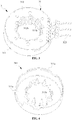
- FIG. 1 is a schematic diagram of the structure of an electromagnetic coil provided by the present application
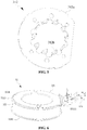
- FIG. 2 is a schematic diagram of the structure of an annular body in FIG. 1
- FIG. 3 is a schematic diagram of the structure of an assembly in FIG. 1
- FIG. 4 is a schematic diagram of the structure of a stator shell in FIG. 1
- FIG. 5 is a schematic diagram of the structure of an electromagnetic pole plate in FIG. 1
- FIG. 6 is a schematic diagram of the structure of a winding in FIG. 1
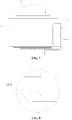
- FIG. 7 is a schematic diagram of the structure of the electromagnetic coil provided with a cap provided by the present application
- FIG. 8 is a partial schematic diagram of an electromagnetic coil sealing part in FIG. 1 .
- an electromagnetic coil including an annular body 1, and an inner peripheral wall of the annular body 1 includes multiple claw poles spaced apart in a circumferential direction; the electromagnetic coil further includes an encapsulation layer 2, and the encapsulation layer 2 is capable of encapsulating an upper annular wall, a lower annular wall, and an outer peripheral wall of the annular body 1, but the encapsulation layer 2 is not disposed between the claw poles.
- the annular body 1 may include two assemblies 3 that abut against in an axial direction.
- the two assemblies 3 may each include a ring-shaped shell 31 and a winding 32 arranged in the shell 31, and an inner peripheral wall of each shell 31 may include multiple claw poles spaced apart in the circumferential direction.
- the encapsulation layer 2 may encapsulate the outer peripheral walls of the two assemblies 3 and the two annular walls, which are opposite to each other in the axial direction, of the two assemblies 3, as is reflected in FIG. 2 . That is, the upper and lower annular walls of the annular body 1 formed by the combination of the two assemblies 3 are encapsulated.
- the shell 31 may include a stator shell 311 and an electromagnetic pole plate 312 that are buckled with each other.
- the stator shell 311 may include a first annular wall 311a, and an inner periphery of the first annular wall 311 a may be provided with multiple first claw poles 311b spaced apart in the circumferential direction and extending in the axial direction.
- Each of the first claw poles 311b may be located on a side of the axial direction of the first annular wall 311a, and each of the first claw poles 311b may be substantially located on the same cylindrical surface, the outer periphery of the first annular wall 311a may be provided with a cylinder wall 311c extending in the same direction with the first claw poles 311b, the cylinder wall 311c may be located axially on the same side of the first annular wall 311a with each first claw pole 311b, the cylinder wall 311c is equivalent to the outer peripheral wall of the assembly 3, and the cylinder wall 311c may be parallel to the cylindrical surface where the first claw poles 311b are located.
- first annular wall 311a, each of the first claw poles 311b, and the cylinder wall 311c may enclose to form an annular concave cavity, and the aforementioned winding 32 may be mounted in the concave cavity.
- the electromagnetic pole plate 312 may include a second annular wall 312a, and an inner periphery of the second annular wall 312a may be provided with multiple second claw poles 312b spaced apart in the circumferential direction and extending in the axial direction.
- Each of the second claw poles 312b may be located on a side of the axial direction of the second annular wall 312a, and each of the second claw poles 312b may be substantially located on the same cylindrical surface.
- the electromagnetic pole plate 312 may be buckled with the stator shell 311 to restrict the winding 32 in the cavity.
- Any one of the second claw poles 312b may be inserted between two adjacent first claw poles 311b, and any one of the first claw poles 311b may be inserted between two adjacent second claw poles 312b, that is, it makes the first claw poles 311b and the second claw poles 312b be inserted alternately with each other, and the alternately inserted first claw poles 311b and second claw poles 312b may form the inner periphery wall of the assembly 3.
- the winding 32 may include a frame 321 and a wire 322 wound around the frame 321, and the frame 321 includes a first collar portion 3211 and a second collar portion 3212.
- the first collar portion 3211 and the second collar portion 3212 are formed by extending radially from both sides of the frame 321.
- the winding 32 wound around the frame 321 is restricted between the first collar portion 3211 and second collar portion 3212 under the action of the first collar portion 3211 and the second collar portion 3212, so that the wire 322 is not easy to fall off the frame 321.
- the frame 321 is made of a thermoplastic material, and the first collar portion 3211 has a pin holding part 32111 protruding from the circumferential surface, a pin 323 may be mounted on the pin holding part 32111, and the pin 323 is electrically connected with the wire 322. In the assembled state, the pin 323 may protrude from the shell 31, and the pins 323 of the two assemblies 3 may be fixed by an insulating sleeve 5.
- a sealing part 3213 is further provided on the frame 321.
- the sealing part 3213 may be a flange structure formed by protruding from the surface of the frame 321, or a flange structure formed by defining a groove on the frame 321.
- a groove is defined at an outer periphery of the first collar portion 3211.
- the groove is similar to a groove-shaped structure formed by shrinking inwardly along the outer periphery of the first collar portion 3211.
- upper and lower ends of the groove form a sealing part 3213.
- the pin holding part 32111 is also provided with a sealing part 3213, the sealing part 3213 protrudes along an axial direction of the pin holding part.
- the sealing part 3213 located at the outer periphery of the first collar portion 3211 may form a closed loop with the sealing part located at the pin holding part 32111.
- a groove is also provided at the outer periphery of the second collar portion 3212. The groove is similar to a groove-shaped structure formed by shrinking inwardly along the outer periphery of the second collar portion 3212. Correspondingly, upper and lower ends of the groove form a sealing part 3213.
- the sealing part 3213 may also be arranged in other forms.
- the cross-sectional shape of the sealing part 3213 is a hook shape, a rectangular shape, a trapezoid shape, or various geometric shapes of a combination thereof.
- the temperature of the molten resin material is relatively high during injection molding, and when the molten resin material flows into the cavity to encapsulate the windings, it may come into contact with the surface of the sealing part provided on the frame, further, the frame 321 is made of a thermoplastic material, it melts when the temperature reaches the melting point of the material, thus the melted sealing part is fused with the melted resin material. After the temperature is cooled, the fused sealing part and the resin material are solidified, so that the frame and the encapsulation layer may be better combined together, and have a better sealing effect.
- the encapsulation layer 2 is provided on the upper annular wall, the lower annular wall and the outer periphery wall of the annular body 1.
- the inner periphery wall including multiple claw poles is not provided with the encapsulation layer 2, so that the injection pressure required in the process of processing the encapsulation layer 2 is small, and the molding difficulty of the encapsulation layer 2 is greatly reduced, which is more conducive to ensuring product quality; at the same time, the required encapsulation materials may also be reduced to lower product manufacturing costs.
- the frame and the encapsulation layer have a good sealing effect after fusion and curing, the moisture entering the annular body 1 through infiltration is not easy to enter the coil winding through the gap between the sealing part 3213 and the encapsulation layer, so that the coil may maintain good water resistance and insulation performance.
- the moisture that enters the annular body 1 through penetration or the like may be easily evaporated and discharged through the gaps between the claw poles and the two assemblies 3, so as to prevent a long-term existence of moisture in the annular body 1 from continuously eroding the joint between the encapsulation layer 2 and the annular body 1, and finally, the encapsulation structure is damaged, which may ensure the insulation and withstand voltage performance of the electromagnetic coil under the condition that high voltage is applied thermally.
- a sealing cap 6 may further be provided on the electromagnetic coil, and the sealing cap 6 may be sealed and fixed with the encapsulation layer 2, so as to seal and isolate the inner peripheral wall of the annular body 1. It may prevent the condensation water above the electromagnetic coil from dripping into the inner peripheral wall of the annular body 1 during use, and thus the rust and corrosion of the claw poles, thereby prolonging the service life of the electromagnetic coil.
- the material of the sealing cap 6 may be plastic, stainless steel and other materials that are not easy to rust, preferably plastic, to improve the bonding ability with the encapsulation layer 2. Specifically, the sealing cap 6 may be fixed to the encapsulation layer 2 by ultrasonic welding or the like.
- a mold is provided by the present application, which is used in the time of injecting the encapsulation layer 2.
- the mold 4 includes an upper mold 41 and a lower mold 42.
- the mold 4 defines a mold cavity A, the mold cavity A is a space inside the mold 4.
- the mold 4 includes an injection port, and the injection port communicates with the mold cavity A for allowing the resin material to flow into the mold cavity A during subsequent injection molding.
- the upper mold 41 includes a first core part 411 and an upper mold body part 412
- the lower mold 42 includes a second core part 421 and a lower mold body part 422.
- the upper mold body part 412 may be matched with the first core part 411. That is, the upper mold body part 412 is provided with a groove structure, and the shape of the groove structure matches the shape of the first core part 411.
- the first core part 411 may be mounted into the groove structure to realize a fixed connection between the first core part 411 and the upper mold body part 412. After the first core part 411 and the upper mold body part 412 are fixedly connected, the first core part 411 protrudes from a lower surface of the upper mold body part 412. In this way, a lower end surface of the first core part 411 forms a first abutting part 4111.
- the first core part 411 protrudes from an axial outer surface of the upper mold body part 412 and forms a first groove part 4112 with the upper mold body part 412.
- the first groove part 4112 is located outside the circumference of the first abutting part 4111.
- the lower mold body part 422 may be matched with the second core part 421. That is, the lower mold body part 422 is provided with a groove structure, and the shape of the groove structure matches the shape of the second core part 421.
- the second core part 421 may be mounted into the groove structure to realize the fixed connection between the second core part 421 and the lower mold body part 422. After the second core part 421 and the lower mold body part 422 are fixedly connected, the second core part 421 protrudes from an upper surface of the lower mold body part 422. In this way, an upper end surface of the second core part 421 forms the second abutting part 4211.
- the second core part 421 protrudes from an axial outer surface of the lower mold body part 422 and forms a second groove part 4212 with the lower mold body part 422.
- the second groove part 4212 is located outside the circumference of the second abutting part 4211.
- a lower annular wall of the annular body 1 may axially abut against the second abutting part 4211, and an upper annular wall of the annular body 1 may axially abut against the first abutting part 4111.
- the molten resin material cannot penetrate the gap between the annular body 1 and the first abutting part 4111 and the second abutting part 4112 to enter between the claw poles, so that no encapsulation layer is present between the claw poles.
- the space between the first groove part 4112 and the upper annular wall of the annular body 1 may be used for accommodating the resin material that encapsulates the upper annular wall.
- the space between the second groove part 4212 and the lower annular wall of the annular body 1 may also be used for accommodating the resin material that encapsulates the lower annular wall.
- the upper annular wall, the lower annular wall and the outer periphery wall of the annular body 1 are provided therein with an encapsulation layer.
- the second core part 421 may further include a second protrusion part 4213, the second protrusion part 4213 protrudes axially along the second abutting part 4211, and a radial size of the second protrusion part 4213 is smaller than a radial size of the second abutting part 4211.
- the second protrusion part 4213 matches with the annular body 1. That is, the second protrusion part 4213 may be inserted into a center hole of the annular body 1 from bottom to top, and its outer wall fits the inner peripheral wall of the annular body 1 to restrict the radial position of the annular body 1.
- the first core part 411 may further include a first protrusion part 4113.
- the first protrusion part 4113 protrudes axially along the first abutting part 4111, and a radial size of the first protrusion part 4113 is smaller than a radial size of the first abutting part 4111.
- the first protrusion part 4113 matches with the annular body 1. That is, the first protrusion part 4113 may be inserted into the center hole of the annular body 1 from top to bottom, and the outer wall of the first protrusion part 4113 fits the inner wall of the annular body 1 to determine the radial position of the annular body 1.
- a second mold is further provided by the present application, which is used in the time of injecting the encapsulation layer 2.
- the mold 4 includes an upper mold 41 and a lower mold 42.
- the mold 4 defines a mold cavity A, the mold cavity A is a space inside the mold 4.
- the mold 4 includes an injection port, and the injection port communicates with the mold cavity A for allowing the resin material to flow into the mold cavity A during subsequent injection molding.
- the lower mold body part 422 may be matched with the second core part 421. That is, the lower mold body part 422 is provided with a groove structure, and the shape of the groove structure matches the shape of the second core part 421.
- the second core part 421 may be fitted into the groove structure to realize the fixed connection between the second core part 421 and the lower mold body part 422. After the second core part 421 and the lower mold body part 422 are fixedly connected, the second core part 421 protrudes from the upper surface of the lower mold body part 422. In this way, the upper end surface of the second core part 421 forms the second abutting part 4211.
- the second core part 421 protrudes from the axial outer surface of the lower mold body part 422 and forms a second groove part 4212 with the lower mold body part 422.
- the second groove part 4212 is located outside the circumference of the second abutting part 4211.
- the lower annular wall of the annular body 1 may axially abut against the second abutting part 4211, and the upper annular wall of the annular body 1 may axially abut against the first abutting part 4111.
- the molten resin material cannot penetrate the gap between the annular body 1 and the first abutting part 4111 and the second abutting part 4112 to enter between the claw poles, so that no encapsulation layer is provided between the claw poles.
- the space between the first groove part 4112 and the upper annular wall of the annular body 1 may be used to accommodate the resin material that encapsulates the upper annular wall.
- the space between the second groove part 4212 and the lower annular wall of the annular body 1 may also be used to accommodate the resin material that encapsulates the lower annular wall.
- the upper annular wall, the lower annular wall and the outer periphery wall of the annular body 1 are provided with an encapsulation layer.
- the second core part 421 may further include a second protrusion part 4213, the second protrusion part 4213 protrudes axially along the second abutting part 4211, and the radial size of the second protrusion part 4213 is smaller than the radial size of the second abutting part 4211.
- the second protrusion part 4213 matches with the annular body 1. That is, the second protrusion part 4213 may be inserted into the center hole of the annular body 1 from bottom to top, and its outer wall fits the inner peripheral wall of the annular body 1 to restrict the radial position of the annular body 1.
- the first core part 411 may further include a first recess part 4114.
- the first recess part 4114 is matched with the second protrusion part 4213.
- the first recess part 4114 is formed by the first abutting part 4111, and the first recess part 4114 is matched with the second protrusion part 4213. That is, the second protrusion part 4213 may be inserted into the first recess part 4114 from bottom to top, and its outer wall fits the inner peripheral wall of the first recess part 4114 to further restrict the position where the first core part 411 abuts against the annular body 1.
- the configuration process of the annular body 1 is an assembling process of the annular body 1.
- the pin 323 is inserted into the frame 321, and the wire 322 on the frame 321 is wound to form the winding 32;
- the winding 32 is mounted into the shell 31 formed by the electromagnetic pole plate 312 and the stator shell 311 to form a single assembly 3; specifically, the electromagnetic pole plate 312 may be used as the base, the winding 32 is mounted on the electromagnetic pole plate 312, and then the stator shell 311 is mounted outside the electromagnetic pole plate 312 to form the assembly 3;
- two assemblies 3 are butted along the axial direction, two electromagnetic pole plates 312 abut against each other, and the first annular walls 311a of the two stator shells are located at the two end faces of the assemblies 3;
- the insulating sleeve 5 is used to fix the pins 323 of the two assemblies 3.
- the formed annular body 1 may enter the next step to process the encapsulation
- the mold 4 may include the upper mold 41 and the lower mold 42.
- the mold 4 defines a mold cavity A, and the mold 4 has an injection port, the injection port communicates with the mold cavity A.
- the upper mold 41 includes the first abutting part 4111 and the first groove part 4112
- the lower mold 42 may include the second abutting part 4211 and the second groove part 4212.
- the annular body 1 is located in the mold cavity A, and the first abutting part 4111 and the upper annular wall are axially closely abutted and matched, and the second abutting part 4211 and the lower annular wall are axially tightly abutted and matched, so that the injection molding material cannot penetrate into the inner hole of the annular body 1 through the matching part.
- an encapsulation layer 2 that only encapsulates the outer periphery wall and the upper and lower annular walls of the annular body 1 may be formed after the injection molding is completed, thereby completing the encapsulation process of the electromagnetic coil.
- S4 may be further implemented after S3.
- the sealing cap 6 is mounted on the encapsulation layer 2 by welding for sealing and isolating the inner peripheral wall of the annular body 1.
- the material of the sealing cap 6 may be plastic, stainless steel and other non-corrosive materials, preferably plastic, so as to improve the bonding ability with the encapsulation layer 2.
- the sealing cap 6 may be fixed to the encapsulation layer 2 by ultrasonic welding, etc., which may prevent the condensed water above the electromagnetic coil from dripping into the inner peripheral wall of the annular body 1 during use, and prevent the claw pole from rusting and corroding, thereby ensuring the service life of the electromagnetic coil.
- the configuration process of the annular body 1 is the assembling process of the annular body 1.
- the pin 323 is inserted into the frame 321, and the wire 322 is wound on the frame 321 to form the winding 32;
- the winding 32 is mounted into the shell 31 formed by the electromagnetic pole plate 312 and the stator shell 311 to form a single assembly 3; specifically, the electromagnetic pole plate 312 may be used as the base, the winding 32 is mounted on the electromagnetic pole plate 312, and then the stator shell 311 is mounted outside the electromagnetic pole plate 312 to form the assembly 3;
- the two assemblies 3 are butted along the axial direction, the two electromagnetic pole plates 312 abut against each other, and the first annular walls 311a of the two stator shells are located at the two end faces of the assemblies 3;
- the insulating sleeve 5 is used to fix the pins 323 of the two assemblies 3.
- the formed annular body 1 may enter the next step to process the en
- the mold 4 may include the upper mold 41 and the lower mold 42.
- the mold 4 defines the mold cavity A, and the mold 4 has the injection port, the injection port communicates with the mold cavity A.
- the upper mold 41 may include the first abutting part 4111, the first groove part 4112 and the first recess part 4114.
- the lower mold 42 may include the second abutting part 4211, the second groove part 4212, and the second protrusion part 4213.
- the annular body 1 is located in the mold cavity A, and the first abutting part 4111 and the upper annular wall are axially closely abutted and matched, and the second abutting part 4211 and the lower annular wall are axially tightly abutted and matched,
- the second protrusion part 4213 is located at the central hole of the annular body 1, and its outer wall fits the inner peripheral wall of the annular body 1, while the first protrusion part 4113 is located at the central hole of the annular body 1, and its outer wall fits the inner wall of the annular body 1.
- an encapsulation layer 2 that only encapsulates the outer periphery wall and the upper and lower annular walls of the annular body 1 may be formed after the injection molding is completed, thereby completing the encapsulation process of the electromagnetic coil.
- S4 may be further implemented after S3.
- the sealing cap 6 is mounted on the encapsulation layer 2 by welding for sealing and isolating the inner peripheral wall of the annular body 1.
- the material of the sealing cap 6 may be plastic, stainless steel and other non-corrosive materials, preferably plastic, to improve the bonding ability with the encapsulation layer 2.
- the sealing cap 6 may be fixed to the encapsulation layer 2 by ultrasonic welding, etc., which may prevent the condensed water above the electromagnetic coil from dripping into the inner peripheral wall of the annular body 1 during use, and prevent the claw pole from rusting and corroding, thereby ensuring the service life of the electromagnetic coil.
- the configuration process of the annular body 1 is the assembling process of the annular body 1.
- the pin 323 is inserted into the frame 321, and the wire 322 is wound on the frame 321 to form the winding 32;
- the winding 32 is mounted into the shell 31 formed by the electromagnetic pole plate 312 and the stator shell 311 to form a single assembly 3; specifically, the electromagnetic pole plate 312 may be used as the base, the winding 32 is mounted on the electromagnetic pole plate 312, and then the stator shell 311 is mounted outside the electromagnetic pole plate 312 to form the assembly 3;
- the two assemblies 3 are butted along the axial direction, the two electromagnetic pole plates 312 abut against each other, and the first annular walls 311a of the two stator shells are located at the two end faces of the assemblies 3;
- the insulating sleeve 5 is used to fix the pins 323 of the two assemblies 3.
- the formed annular body 1 may enter the next step to process the en
- the mold 4 may include the upper mold 41 and the lower mold 42.
- the mold 4 defines a mold cavity A, and the mold 4 has an injection port, the injection port communicates with the mold cavity A.
- the upper mold 41 may include the first abutting part 4111, the first groove part 4112 and the first recess part 4114.
- the lower mold 42 may include the second abutting part 4211, the second groove part 4212, and the second protrusion part 4213.
- the annular body 1 is located in the mold cavity A, and the first abutting part 4111 and the upper annular wall are axially closely abutted and matched, and the second abutting part 4211 and the lower annular wall are axially tightly abutted and matched.
- the second protrusion part 4213 is located at the central hole of the annular body 1, and its outer wall fits the inner peripheral wall of the annular body 1, the second protrusion part 4213 is matched with the first recess part.
- an encapsulation layer 2 that only encapsulates the outer periphery wall and the upper and lower annular walls of the annular body 1 may be formed after the injection molding is completed, thereby completing the encapsulation process of the electromagnetic coil.
- S4 may be further implemented after S3.
- the sealing cap 6 is mounted on the encapsulation layer 2 by welding for sealing and isolating the inner peripheral wall of the annular body 1.
- the material of the sealing cap 6 may be plastic, stainless steel and other non-corrosive materials, preferably plastic, to improve the bonding ability with the encapsulation layer 2.
- the sealing cap 6 may be fixed to the encapsulation layer 2 by ultrasonic welding, etc., which may prevent the condensed water above the electromagnetic coil from dripping into the inner peripheral wall of the annular body 1 during use, and prevent the claw pole from rusting and corroding, thereby ensuring the service life of the electromagnetic coil.
- the present application does not limit the relationship between the first abutting part 4111 and the first core part 411, and the relationship between the first groove part 4112 and the upper mold body part 412. It also does not limit the relationship between the second abutting part 4211 and the second core part 421, and the relationship between the second groove part 4212 and the lower mold body part 422. In the technical solution of the present application, it is only necessary to have the first abutting part 4111, the first groove part 4112, the second abutting part 4211, and the second groove part 4212 in the mold 4.
- first core part 411 and the upper mold body part 412 are fixedly connected, and the second core part 421 and the lower mold body part 422 are fixedly connected.
- first core part 411 and the upper mold body part 412 form the first groove part 4112
- second core part 421 and the lower mold body part 422 form the second groove part 4212.
- first core part 411 and the upper mold body part 412, the second core part 421 and the lower mold body part 422 may be selected or all formed integrally.
- first core part 411 and the upper mold body part 412 are fixedly connected, the shapes of the first core part 411 and the upper mold body part 412 may be appropriately changed.
- first groove part 4112 is formed or partially formed on the first core part 411, and the second core part 421 and the lower mold body part 422 may also adopt similar structures, which is not repeated here.
Landscapes
- Engineering & Computer Science (AREA)
- Power Engineering (AREA)
- Manufacturing & Machinery (AREA)
- Mechanical Engineering (AREA)
- General Engineering & Computer Science (AREA)
- Electromagnets (AREA)
- Moulds For Moulding Plastics Or The Like (AREA)
- Injection Moulding Of Plastics Or The Like (AREA)
- Insulating Of Coils (AREA)
- Housings And Mounting Of Transformers (AREA)
- Manufacturing Cores, Coils, And Magnets (AREA)
- Manufacture Of Motors, Generators (AREA)
Applications Claiming Priority (3)
| Application Number | Priority Date | Filing Date | Title |
|---|---|---|---|
| CN201811458385.0A CN111251539A (zh) | 2018-11-30 | 2018-11-30 | 模具及电磁线圈的制造方法 |
| CN201811453683.0A CN111255939A (zh) | 2018-11-30 | 2018-11-30 | 一种电磁线圈 |
| PCT/CN2019/121971 WO2020108617A1 (zh) | 2018-11-30 | 2019-11-29 | 一种电磁线圈、模具及电磁线圈的制造方法 |
Publications (2)
| Publication Number | Publication Date |
|---|---|
| EP3889481A1 true EP3889481A1 (de) | 2021-10-06 |
| EP3889481A4 EP3889481A4 (de) | 2022-09-14 |
Family
ID=70854696
Family Applications (1)
| Application Number | Title | Priority Date | Filing Date |
|---|---|---|---|
| EP19888896.8A Pending EP3889481A4 (de) | 2018-11-30 | 2019-11-29 | Elektromagnetische spule, giessform und herstellungsverfahren für elektromagnetische spule |
Country Status (5)
| Country | Link |
|---|---|
| US (2) | US20240269906A1 (de) |
| EP (1) | EP3889481A4 (de) |
| JP (2) | JP7285926B2 (de) |
| KR (1) | KR102587074B1 (de) |
| WO (1) | WO2020108617A1 (de) |
Cited By (1)
| Publication number | Priority date | Publication date | Assignee | Title |
|---|---|---|---|---|
| EP4686580A1 (de) * | 2024-08-02 | 2026-02-04 | STAMP Systems Europe Sp. z o.o. | Positionselement für eine patrix, eine matrix und verfahren zur einbettung des positionselements in die patrix |
Families Citing this family (2)
| Publication number | Priority date | Publication date | Assignee | Title |
|---|---|---|---|---|
| CN115704638B (zh) * | 2021-08-11 | 2025-01-10 | 青岛海尔电冰箱有限公司 | 磁场保鲜装置和风冷式制冷设备 |
| CN114102971A (zh) * | 2021-10-09 | 2022-03-01 | 宁波万盛实业有限公司 | 一种导磁环组件的注塑模具 |
Family Cites Families (22)
| Publication number | Priority date | Publication date | Assignee | Title |
|---|---|---|---|---|
| JPH06155506A (ja) * | 1992-11-25 | 1994-06-03 | Kinugawa Rubber Ind Co Ltd | 樹脂成形品の中空射出成形法 |
| JPH06335226A (ja) * | 1993-05-18 | 1994-12-02 | Asmo Co Ltd | Pm型ステッピングモータ |
| JPH0737718A (ja) * | 1993-06-28 | 1995-02-07 | Du Pont Kk | ボビン内包の封止成形部品および内包ボビンの封止方法 |
| JPH0963835A (ja) * | 1995-08-24 | 1997-03-07 | Tokimec Inc | モールドコイル |
| JP2001095193A (ja) | 1999-09-24 | 2001-04-06 | Honda Motor Co Ltd | ステータアセンブリ、その射出成形方法および装置 |
| JP2001267121A (ja) * | 2000-03-15 | 2001-09-28 | Saginomiya Seisakusho Inc | モールドコイルとその製造方法 |
| JP4519258B2 (ja) * | 2000-03-31 | 2010-08-04 | 株式会社鷺宮製作所 | 電動弁用防水コイル |
| JP2002013659A (ja) * | 2000-06-29 | 2002-01-18 | Denso Corp | 電磁弁 |
| CN1220320C (zh) | 2000-12-26 | 2005-09-21 | 太平洋工业株式会社 | 步进马达的定子 |
| CN101901662B (zh) * | 2010-08-13 | 2016-04-13 | 浙江三花制冷集团有限公司 | 一种电磁线圈 |
| CN102758947A (zh) * | 2011-04-27 | 2012-10-31 | 浙江三花股份有限公司 | 一种电子膨胀阀及其线圈 |
| CN102380931B (zh) * | 2011-12-06 | 2014-06-18 | 爱普科斯科技(无锡)有限公司 | 一种注塑封装工艺模具 |
| JP5965712B2 (ja) | 2012-04-25 | 2016-08-10 | 株式会社不二工機 | 電動弁用駆動モータのステータ |
| JP5786846B2 (ja) * | 2012-12-19 | 2015-09-30 | 株式会社デンソー | ソレノイド |
| CN104283397B (zh) | 2013-07-10 | 2018-05-29 | 浙江三花汽车零部件有限公司 | 一种步进电机线圈 |
| JP6427333B2 (ja) | 2014-04-16 | 2018-11-21 | 株式会社不二工機 | 電磁的駆動コイル装置の成形方法 |
| JP6434236B2 (ja) * | 2014-07-03 | 2018-12-05 | 株式会社不二工機 | 電動弁 |
| JP6678322B2 (ja) * | 2015-11-04 | 2020-04-08 | パナソニックIpマネジメント株式会社 | 電磁石装置およびそれを備えた移動体 |
| CN109792186B (zh) | 2016-09-16 | 2021-11-02 | 日本电产株式会社 | 马达 |
| CN108119699B (zh) | 2016-11-30 | 2021-12-07 | 盾安环境技术有限公司 | 一种导阀和主阀体连接结构及车用空调系统电子膨胀阀 |
| JP2018143049A (ja) | 2017-02-28 | 2018-09-13 | 日本電産テクノモータ株式会社 | モータの製造方法およびモータ |
| CN207206962U (zh) * | 2017-09-09 | 2018-04-10 | 台州市三鼎模塑有限公司 | 一种定子骨架的注塑模具 |
-
2019
- 2019-11-29 WO PCT/CN2019/121971 patent/WO2020108617A1/zh not_active Ceased
- 2019-11-29 EP EP19888896.8A patent/EP3889481A4/de active Pending
- 2019-11-29 KR KR1020217018830A patent/KR102587074B1/ko active Active
- 2019-11-29 JP JP2021529837A patent/JP7285926B2/ja active Active
- 2019-11-29 US US17/296,040 patent/US20240269906A1/en not_active Abandoned
-
2022
- 2022-08-15 JP JP2022129289A patent/JP7454613B2/ja active Active
-
2024
- 2024-12-20 US US18/990,359 patent/US20250144856A1/en active Pending
Cited By (1)
| Publication number | Priority date | Publication date | Assignee | Title |
|---|---|---|---|---|
| EP4686580A1 (de) * | 2024-08-02 | 2026-02-04 | STAMP Systems Europe Sp. z o.o. | Positionselement für eine patrix, eine matrix und verfahren zur einbettung des positionselements in die patrix |
Also Published As
| Publication number | Publication date |
|---|---|
| US20240269906A1 (en) | 2024-08-15 |
| KR20210093987A (ko) | 2021-07-28 |
| JP2022510185A (ja) | 2022-01-26 |
| JP2022173161A (ja) | 2022-11-17 |
| EP3889481A4 (de) | 2022-09-14 |
| WO2020108617A1 (zh) | 2020-06-04 |
| KR102587074B1 (ko) | 2023-10-10 |
| US20250144856A1 (en) | 2025-05-08 |
| JP7454613B2 (ja) | 2024-03-22 |
| JP7285926B2 (ja) | 2023-06-02 |
Similar Documents
| Publication | Publication Date | Title |
|---|---|---|
| US20250144856A1 (en) | Electromagnetic coil, mold, and electromagnetic coil manufacturing method | |
| US6787950B2 (en) | Stator for an electric drive with a tubular insulator as lost casting mold | |
| EP0967707B1 (de) | Bürstenloser Pumpenmotor aus trennbarem Blechpaket mit flüssigem Kühlsystem | |
| US9793038B2 (en) | Electromagnetic drive coil unit and molding method thereof | |
| WO2013042342A1 (en) | Motor and method of manufacturing motor | |
| US20080042498A1 (en) | Method for manufacturing an electric machine and electric machine manufactured according to said method | |
| CN204118908U (zh) | 马达 | |
| US20170117781A1 (en) | Method of manufacturing laminated core | |
| JPS62166755A (ja) | 永久磁石付回転子 | |
| US9787150B2 (en) | Rotor of brushless motor | |
| CN111255939A (zh) | 一种电磁线圈 | |
| EP3301692A1 (de) | Spule zur formung eines solenoids für ein einspritzventil, leistungsgruppenanordnung, einspritzventil und verfahren zur herstellung einer leistungsgruppenanordnung | |
| JP2002010545A (ja) | 永久磁石回転子 | |
| US12027928B2 (en) | Insulator and motor | |
| KR100585682B1 (ko) | 왕복동식 모터의 고정자 및 그 제조 방법 | |
| CN111251539A (zh) | 模具及电磁线圈的制造方法 | |
| CN117438209A (zh) | 一种电磁线圈的制备方法 | |
| CN104756367A (zh) | 用于电动机的转子 | |
| JP7072427B2 (ja) | モータ | |
| JP2003142325A (ja) | 点火コイル | |
| JP4563088B2 (ja) | 電磁アクチュエータ | |
| CN222052712U (zh) | 一种外转子电机的定子结构 | |
| CN214505180U (zh) | 一种电磁线圈 | |
| KR100677262B1 (ko) | 왕복동식 모터의 고정자 및 그 제조 방법 | |
| JP3596488B2 (ja) | 内燃機関用点火コイル |
Legal Events
| Date | Code | Title | Description |
|---|---|---|---|
| STAA | Information on the status of an ep patent application or granted ep patent |
Free format text: STATUS: THE INTERNATIONAL PUBLICATION HAS BEEN MADE |
|
| PUAI | Public reference made under article 153(3) epc to a published international application that has entered the european phase |
Free format text: ORIGINAL CODE: 0009012 |
|
| STAA | Information on the status of an ep patent application or granted ep patent |
Free format text: STATUS: REQUEST FOR EXAMINATION WAS MADE |
|
| 17P | Request for examination filed |
Effective date: 20210528 |
|
| AK | Designated contracting states |
Kind code of ref document: A1 Designated state(s): AL AT BE BG CH CY CZ DE DK EE ES FI FR GB GR HR HU IE IS IT LI LT LU LV MC MK MT NL NO PL PT RO RS SE SI SK SM TR |
|
| DAV | Request for validation of the european patent (deleted) | ||
| DAX | Request for extension of the european patent (deleted) | ||
| REG | Reference to a national code |
Ref country code: DE Ref legal event code: R079 Free format text: PREVIOUS MAIN CLASS: F16K0031060000 Ipc: F16K0031040000 |
|
| A4 | Supplementary search report drawn up and despatched |
Effective date: 20220811 |
|
| RIC1 | Information provided on ipc code assigned before grant |
Ipc: B29C 45/26 20060101ALI20220805BHEP Ipc: H02K 15/12 20060101ALI20220805BHEP Ipc: H02K 1/14 20060101ALI20220805BHEP Ipc: H02K 5/08 20060101ALI20220805BHEP Ipc: H02K 37/00 20060101ALI20220805BHEP Ipc: F16K 31/04 20060101AFI20220805BHEP |
|
| STAA | Information on the status of an ep patent application or granted ep patent |
Free format text: STATUS: EXAMINATION IS IN PROGRESS |