EP3889366B1 - Dispositif de fixation pour une installation technique sanitaire et procédé d'installation - Google Patents
Dispositif de fixation pour une installation technique sanitaire et procédé d'installation Download PDFInfo
- Publication number
- EP3889366B1 EP3889366B1 EP21164049.5A EP21164049A EP3889366B1 EP 3889366 B1 EP3889366 B1 EP 3889366B1 EP 21164049 A EP21164049 A EP 21164049A EP 3889366 B1 EP3889366 B1 EP 3889366B1
- Authority
- EP
- European Patent Office
- Prior art keywords
- fastening device
- sanitary
- fastening
- clamping
- mounting
- Prior art date
- Legal status (The legal status is an assumption and is not a legal conclusion. Google has not performed a legal analysis and makes no representation as to the accuracy of the status listed.)
- Active
Links
- 238000009434 installation Methods 0.000 title claims description 14
- 238000000034 method Methods 0.000 title claims description 5
- 230000007246 mechanism Effects 0.000 claims description 30
- 238000006073 displacement reaction Methods 0.000 claims description 18
- 230000000087 stabilizing effect Effects 0.000 claims description 6
- 230000000712 assembly Effects 0.000 description 10
- 238000000429 assembly Methods 0.000 description 10
- 238000010276 construction Methods 0.000 description 8
- 239000012530 fluid Substances 0.000 description 7
- XLYOFNOQVPJJNP-UHFFFAOYSA-N water Substances O XLYOFNOQVPJJNP-UHFFFAOYSA-N 0.000 description 5
- 238000012986 modification Methods 0.000 description 4
- 230000004048 modification Effects 0.000 description 4
- 239000002351 wastewater Substances 0.000 description 3
- 239000003570 air Substances 0.000 description 2
- 229910052782 aluminium Inorganic materials 0.000 description 2
- XAGFODPZIPBFFR-UHFFFAOYSA-N aluminium Chemical compound [Al] XAGFODPZIPBFFR-UHFFFAOYSA-N 0.000 description 2
- 238000005452 bending Methods 0.000 description 2
- 230000000694 effects Effects 0.000 description 2
- 239000013505 freshwater Substances 0.000 description 2
- 230000006978 adaptation Effects 0.000 description 1
- 230000000903 blocking effect Effects 0.000 description 1
- 230000008859 change Effects 0.000 description 1
- 230000001934 delay Effects 0.000 description 1
- 230000001066 destructive effect Effects 0.000 description 1
- 239000007788 liquid Substances 0.000 description 1
- 239000000463 material Substances 0.000 description 1
- 229910052751 metal Inorganic materials 0.000 description 1
- 239000002184 metal Substances 0.000 description 1
- 230000002441 reversible effect Effects 0.000 description 1
- 230000007704 transition Effects 0.000 description 1
Images


Classifications
-
- E—FIXED CONSTRUCTIONS
- E03—WATER SUPPLY; SEWERAGE
- E03D—WATER-CLOSETS OR URINALS WITH FLUSHING DEVICES; FLUSHING VALVES THEREFOR
- E03D11/00—Other component parts of water-closets, e.g. noise-reducing means in the flushing system, flushing pipes mounted in the bowl, seals for the bowl outlet, devices preventing overflow of the bowl contents; devices forming a water seal in the bowl after flushing, devices eliminating obstructions in the bowl outlet or preventing backflow of water and excrements from the waterpipe
- E03D11/13—Parts or details of bowls; Special adaptations of pipe joints or couplings for use with bowls, e.g. provisions in bowl construction preventing backflow of waste-water from the bowl in the flushing pipe or cistern, provisions for a secondary flushing, for noise-reducing
- E03D11/14—Means for connecting the bowl to the wall, e.g. to a wall outlet
- E03D11/143—Mounting frames for toilets and urinals
-
- E—FIXED CONSTRUCTIONS
- E03—WATER SUPPLY; SEWERAGE
- E03C—DOMESTIC PLUMBING INSTALLATIONS FOR FRESH WATER OR WASTE WATER; SINKS
- E03C1/00—Domestic plumbing installations for fresh water or waste water; Sinks
- E03C1/12—Plumbing installations for waste water; Basins or fountains connected thereto; Sinks
- E03C1/32—Holders or supports for basins
- E03C1/322—Holders or supports for basins connected to the wall only
- E03C1/324—Holders or supports for basins connected to the wall only adjustable
-
- E—FIXED CONSTRUCTIONS
- E03—WATER SUPPLY; SEWERAGE
- E03C—DOMESTIC PLUMBING INSTALLATIONS FOR FRESH WATER OR WASTE WATER; SINKS
- E03C1/00—Domestic plumbing installations for fresh water or waste water; Sinks
- E03C1/02—Plumbing installations for fresh water
- E03C2001/028—Alignment aids for plumbing installations
Definitions
- the invention relates to a fastening device for a sanitary system, with a carrier body, to which at least one sanitary engineering component or at least one sanitary engineering assembly can be fastened, a first assembly body and a second assembly body spaced apart from the first assembly body, the first assembly body being connected to the carrier body and is designed to be attached to a first drywall profile of a stud frame, and the second assembly body is connected to the carrier body and set up to be attached to a second drywall profile of the stud frame spaced apart from the first drywall profile, and an adjustment mechanism by means of which the distance between the carrier body and the first and second mounting body and the distance between the first mounting body and the second mounting body is variable.
- the invention relates to a fastening system for a sanitary installation, with a fastening device and at least one sanitary technical component fastened to the fastening device or at least one sanitary technical subassembly fastened to the fastening device.
- the invention relates to a method for fastening a mounting body of a fastening device for a sanitary installation to a dry construction profile of a stud frame.
- sanitary components or sanitary assemblies such as for example, fluid connections to be attached to an existing drywall stud frame.
- Corresponding stud frames regularly consist of a plurality of drywall profiles spaced apart from one another, with the drywall profiles usually being used to fix the fastening device.
- wooden panels are used as fastening devices, to which the sanitary engineering components or sanitary engineering assemblies to be fastened are screwed.
- the wooden panels are to be equipped with mounting bodies, which are then to be attached to the drywall profiles of the stud frame.
- the object on which the invention is based is therefore to improve the adaptability of fastening devices to different drywall posts.
- the carrier body being designed as a grooved plate with a number of grooves and the adjustment mechanism being a rail system with two comprises adjustment clamping bodies, wherein the first mounting body is connected to a first adjustment clamping body and the first adjustment clamping body can be displaced and clamped in a first groove of the carrier body, and the second mounting body is connected to a second adjustment clamping body and the second adjustment clamping body can be displaced in a second groove of the carrier body and can be jammed.
- the fastening device can be adapted to the installation dimensions specified by the stud frame. Furthermore, the fastening device according to the invention enables positioning of the sanitary engineering component or the sanitary engineering assembly group relative to the stud frame, so that an intended component position or assembly group position can be realized with an extremely low expenditure of time and thus also cost.
- sanitary engineering components or sanitary engineering assemblies can also be fastened to the carrier body.
- the sanitary engineering components or the sanitary engineering assemblies can be attached to the carrier body either directly or via one or more intermediate members, such as wall plates, housing parts or additional carrier elements.
- the sanitary components can be connected to an exposed fitting, for example.
- the sanitary engineering components or the sanitary engineering assemblies can be or include, for example, fluid connections or fluid lines.
- the sanitary engineering components or the sanitary engineering assemblies can be or include supply or disposal connections.
- the sanitary engineering components or the sanitary engineering assemblies are or include fresh water, waste water or air connections.
- the sanitary engineering components or the sanitary engineering assemblies can be or include fresh water, waste water or air lines.
- the sanitary engineering component or the sanitary engineering assembly can also be or include a fan housing.
- the carrier body can be a carrier plate.
- the support plate can be made of metal, for example, in particular aluminum.
- the at least one mounting body can be set up with a Drywall profile of a stud frame to be crimped, screwed and/or riveted.
- the at least one assembly body can have a Z-profile or an L-profile.
- the sanitary installation in which the fastening device according to the invention can be used, can be used, for example, to supply materials, such as water, air or gas, and/or to dispose of waste water.
- the fastening device has a first mounting body and a second mounting body spaced apart from the first mounting body.
- the first assembly body is connected to the carrier body and set up to be attached to a first dry construction profile of a stud frame.
- the second assembly body is connected to the carrier body and set up to be fastened to a second dry construction profile of the stud frame spaced apart from the first dry construction profile.
- the distance between the first mounting body and the second mounting body can preferably be changed by means of the adjustment mechanism.
- the first and the second assembly body are preferably arranged opposite one another and/or on opposite sides of the carrier body.
- the distance between the first and the second mounting body can be adjusted to the distance between the first and the second drywall profile of the stud frame to which the mounting body is to be attached.
- the distance between the first assembly body and the carrier body can preferably be changed by means of the adjustment mechanism.
- the distance between the second assembly body and the carrier body can preferably be changed by means of the adjustment mechanism.
- the distance between the first mounting body and the second mounting body can be changed in one or more spatial directions by means of the adjustment mechanism.
- the distance between the first mounting body and the second mounting body can be changed, for example, in the transverse direction, so that the width of the change in distance Fastening device is adjustable.
- the distance between the first mounting body and the second mounting body can be changed perpendicularly to the transverse direction, so that a depth offset of the drywall profiles of the stud frame used for fastening can be compensated for by changing the distance.
- the vertical distance between the first assembly body and the second assembly body can be variable, so that a height offset of the assembly points on the drywall profiles to which the assembly body is to be attached can be compensated.
- the distance between the first assembly body and the carrier plate and/or the distance between the second assembly body and/or the carrier plate can also be variable in one or more spatial directions by means of the adjustment mechanism.
- the distance between the first mounting body and the support plate and/or between the second mounting body and the support plate can be changeable perpendicularly to the transverse direction, so that the installation depth of the at least one sanitary engineering component or the at least one sanitary engineering assembly group can be adjusted via the fastening device.
- the adjustment mechanism of the fastening device is preferably designed to be reversible and detachable without destroying it, so that distances set via the adjustment mechanism can be subsequently corrected.
- this allows a practical and quick subsequent adjustment of the configuration of the fastening device.
- the at least one sanitary engineering component or the at least one sanitary engineering assembly group can be fastened at different positions on the carrier body.
- the carrier body can, for example, specify fastening positions for one or more sanitary engineering components or sanitary engineering assemblies.
- the carrier body has a displacement system, via which the at least one sanitary engineering component or the at least one sanitary engineering assembly group can be displaced on the carrier body.
- the sanitary engineering component or the sanitary engineering assembly can preferably be displaced in the transverse direction via the displacement system.
- the displacement system can also be used to adjust the height. The distance between the one or more sanitary engineering components or sanitary engineering assemblies and the mounting bodies used for attachment can be adjusted via the displacement system.
- the displacement system is designed as a rail system with at least one fastening clamp body and at least one groove.
- the at least one sanitary engineering component or the at least one sanitary engineering assembly can be fastened to the fastening clamp body and the fastening clamp body can be displaced and/or clamped in the groove.
- the fastening clamp body can have, for example, one or more threaded holes for screwing on the sanitary engineering component or the sanitary engineering assembly.
- the groove of the sliding system designed as a rail system can be a T-groove.
- the fastening clamp body can be a sliding nut, in particular an elongated nut or an elongated sliding block for a T-slot.
- the displacement system designed as a rail system can also have a plurality of grooves, with the plurality of grooves being arranged at a distance from one another and/or running parallel to one another.
- a fastening device is also advantageous in which the adjustment mechanism comprises a rail system with at least one adjustment clamping body and at least one groove.
- the at least one assembly body is connected to the adjustment clamping body and the adjustment clamping body can be displaced and/or clamped in the groove.
- the fastening device has two mounting bodies, the two mounting bodies can preferably each be slid over the rail system.
- the groove of the rail system Adjustment mechanism can be a T-slot.
- the adjustable clamping body can be a slide nut, in particular an elongated nut or an elongated sliding block for a T-slot.
- the rail system of the adjusting mechanism can also have a number of grooves, with the number of grooves being arranged at a distance from one another and/or being able to run parallel to one another.
- a fastening device is also preferred in which the at least one assembly body is fastened to a clamping body receiving member and the adjustment clamping body is fixed, in particular clamped, to the clamping body receiving member.
- the clamping body receiving member can have a groove, for example a T-groove, in which the adjustment clamping body is clamped.
- the sprag receiving member may be a grooved plate.
- the mounting body can be connected to the clamping body receiving member in a materially bonded, form-fitting and/or non-positive manner. In particular, the assembly body is screwed and/or glued to the clamping body receiving member.
- a first mounting body is pressed flat against the first clamping body receiving member by means of a first stabilizing plate for fixing to a first clamping body receiving member.
- a second mounting body is pressed flat against the second clamping body receiving member by means of a second stabilizing plate for fixing to a second clamping body receiving member.
- the carrier body comprises at least one groove of the displacement system.
- the displacement system and the adjustment mechanism can also use the same grooves.
- both a fastening clamp body and an adjustment clamp body can be fastened, in particular clamped, in a groove.
- a fastening device is also advantageous in which the grooves of the grooved plate run parallel to one another.
- the carrier body can be a T-slot rail.
- the adjustment mechanism comprises a rail system with two adjustment clamping bodies, a first mounting body being connected to a first adjustment clamping body and the first adjustment clamping body being displaceable and/or clampable in a first groove of the carrier body.
- a second mounting body is connected to a second adjustment clamping body and the second adjustment clamping body can be displaced and/or clamped in a second groove of the carrier body.
- the fastening clamping body of the displacement system can be displaced and/or clamped in a third groove of the carrier body.
- the first and second grooves of the carrier body assigned to the adjustment mechanism and the third groove of the carrier body assigned to the displacement system can run on the same side or on different sides of the carrier body.
- the first and second grooves assigned to the adjustment mechanism run on the rear side of the carrier body and the third groove assigned to the displacement system runs on the front side of the carrier body.
- the carrier body and the at least one Assembly body non-destructively and reversibly detachably connected to each other.
- the non-destructive and reversibly detachable connection between the carrier body and the at least one assembly body allows subsequent correction of the configuration of the fastening device.
- the at least one sanitary component is designed as a fluid connection or the at least one sanitary component includes a fluid connection.
- the fluid connection can, for example, be a liquid connection, in particular a water connection.
- the object on which the invention is based is also achieved by a method of the type mentioned at the outset, in which the assembly body is crimped to the drywall profile at a fastening point.
- the fastening device is designed according to one of the above embodiments.
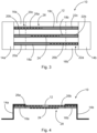
- the 1 shows a fastening system 100 for a sanitary installation.
- the fastening system 100 comprises a fastening device 10 and two sanitary engineering components 102a, 102b fastened to the fastening device 10.
- the sanitary engineering components 102a, 102b are designed as fluid connections, namely as water connections.
- the sanitary engineering component 102a is a hot water connection.
- Sanitary component 102b is a cold water connection.
- the fastening device 10 has a carrier body 12 to which the sanitary engineering components 102a, 102b are fastened.
- the carrier body 12 is a carrier plate made of aluminum.
- the carrier plate 12 is designed as a grooved plate with a plurality, namely three, spaced apart and parallel grooves 18a-18c.
- Adjusting clamping bodies 26a, 26b of an adjusting mechanism 28 are arranged in the grooves 18a, 18c.
- the grooves 18a-18c of the carrier body 12 are designed as T-grooves.
- the adjustment clamping bodies 26a, 26b are elongated T-nuts.
- the sanitary engineering components 102a, 102b are fastened to a fastening clamp body 24.
- the mounting clip body 24 is also an elongated T-nut.
- the sanitary engineering components 102a, 102b can also be fastened to different fastening clamp bodies.
- the adjustment clamping body 26a is connected to a mounting body 14a via a clamping body receiving member 16a.
- the adjustment clamping body 26b is connected to the mounting body 14b via a clamping body receiving member 16b.
- the adjustment clamping bodies 26a, 26b are clamped to the clamping body receiving members 16a, 16b.
- the sprag receiving members 16a, 16b also have three grooves 20a-20c, 22a-22c running parallel to one another and spaced apart from one another, with the grooves 20a-20c, 22a-22c being designed as T-grooves. Accordingly, the clamping body receiving members 16a, 16b are also designed as grooved plates.
- the mounting bodies 14a, 14b are each set up to be attached to a drywall profile 104a, 104b of a stud frame.
- the 2 shows that the distance between the mounting bodies 14a, 14b can be changed by the adjustment mechanism 28, which includes the grooves 18a, 18c and the adjustment clamping bodies 26a, 26b. Furthermore, the distance between the mounting body 14a and the carrier body 12 and the distance between the mounting body 14b and the carrier body 12 can also be changed via the adjusting mechanism.
- the fastening device 10 can thus be adapted to the installation dimensions specified by the stud frame. Furthermore, the fastening device 10 allows the sanitary engineering components 102a, 102b to be positioned relative to the framework.
- the mounting bodies 14a, 14b are arranged opposite one another and on opposite sides of the carrier body 12.
- the drywall profiles 104a, 104b of the stud frame are transversely spaced from each other. The distance in the transverse direction between the drywall profiles 104a, 104b can be set on the fastening device 10 by means of the adjustment mechanism 28 without great effort.
- the distance between the assembly bodies 14a, 14b can be changed in the transverse direction by means of the adjustment mechanism 28.
- the distance between the mounting bodies can also be changed in one or more other spatial directions.
- a depth offset of the drywall profiles 104a, 104b can also be compensated for, for example.
- a height distance between assembly points of the dry construction profiles 104a, 104b can also be compensated for by a corresponding adjustability.
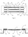
- FIGS 3 and 4 show a fastening device 10 in which the minimum distance between the mounting bodies 14a, 14b is set.
- FIGS 5 and 6 show the same fastening device 10, wherein the distance between the mounting bodies 14a, 14b has been increased by the adjustment mechanism 28.
- the adjustment mechanism 28 includes a rail system with two adjustment clamping bodies 26a, 26b and grooves 18a-18c, 20a-20c, 22a-22c.
- the adjustment clamping bodies 26a, 26b are elongated T-nuts.
- the grooves 18a-18c, 20a-20c, 22a-22c are T-grooves.
- the adjusting clamping body 26a can be displaced and clamped in the grooves 18c, 20c, 22c.
- the adjustment clamping body 26b can be displaced and clamped in the grooves 18a, 20a, 22a.
- the adjustment clamping bodies 26a, 26b could also be inserted into the grooves 18b, 20b, 22b.
- the adjustment clamping bodies 26a, 26b each have at least two clamping members, via which a clamping effect can be generated in the respective grooves 18a-18c, 20a-20c, 22a-22c.
- the clamping members can be screws, for example, which are screwed into threaded holes in the adjustment clamping bodies 26a, 26b.
- the Figures 7 and 8 show that the sanitary engineering components 102a, 102b can be fastened at different positions on the carrier body 12 or even at a distance from the carrier body.
- the support body 12 has a displacement system, via which the technical sanitary components 102a, 102b can be displaced on the support body 12.
- the displacement system is designed as a rail system with at least one fastening clamp body 24 and a groove 18b.
- the sanitary engineering components 102a, 102b are attached to the fastening clamp body 24, the fastening clamp body 24 being displaceable and clampable in the groove 18b.
- the fastening clamp body 24 has at least one clamping member, by means of which a clamping effect can be generated.
- the clamping member can be a screw which is screwed into a threaded hole of the fastening clamp body 24 .
- the attachment clamp body 24 is designed as a T-nut in this embodiment, with the groove 18b being a T-groove.
- the carrier body 12 thus includes grooves 18a, 18c, which are used by the adjustment mechanism 28 and a groove 18b, which is used by the displacement system for the sanitary components 102a, 102b.
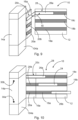
- the 9 shows a fastening device 10 in which the distance between the mounting body 14a and the carrier body 12 can be changed in two spatial directions.
- the adjustment mechanism 28 has an adjustment clamping body 26a, which is angled.
- the angled adjustment clamping body 26 has a bending angle ⁇ of 90 degrees.
- the bending angle ⁇ can also have a different value.
- the sprag receiving member 16a can be moved along a first leg of the adjustment sprag 26a.
- the carrier body 12 can be adjusted along a second leg of the adjustment clamping body 26a.
- the distance between the mounting body 14a and the carrier body 12 in the transverse direction and perpendicular to the transverse direction can be adjusted by moving the clamping body receiving element 16a and the carrier body 12 along the legs of the adjustment clamping body 26a. In this way, in addition to adjusting the width of the fastening device 10, the installation depth of the one or more sanitary components 102a, 102b attached to the support body 12 can be adjusted at the same time.
- the 10 shows that the assembly body 14a is attached to the attachment points 30a, 30b on the drywall profile 104a.
- the dry construction profile 104a is a CW profile.
- the mounting body 14a is crimped at the attachment points 30a, 30b with the drywall profile 104a.
- the 11 shows that the attachment can also take place at the illustrated attachment points 30a, 30b.
- the drywall profile 104b is a UA profile and the mounting body 14a is screwed or riveted to the drywall profile 104b.
- the 12 and 13 12 show that sprag receiving member 16a may be connected to mounting body 14a at attachment points 32a, 32b.
- the mounting body 14a and the Clamp body receiving member 16a screwed together, riveted or glued.
Claims (11)
- Dispositif de fixation (10) pour une installation sanitaire, avec- un corps de support (12) sur lequel peut être fixé au moins une pièce sanitaire (102a, 102b) ou au moins un module sanitaire,- un premier corps de montage (14a) et un deuxième corps de montage (14b) espacé dudit premier corps de montage (14a), ledit premier corps de montage (14a) étant relié au corps de support (12) et destiné à être fixé à un premier profilé de pose à sec (104a) d'une première ossature de coffrage, et ledit deuxième corps de montage (14b) étant relié au corps de support (12) et destiné à être fixé à un deuxième profilé de pose à sec (104b) de l'ossature de coffrage, espacé du premier profilé de pose à sec (104a), et- un mécanisme de réglage (28) au moyen duquel la distance entre le corps de support (12) et les premier et deuxième corps de montage (14a, 14b) et la distance entre le premier corps de montage (14a) et le deuxième corps de montage (14b) peuvent être modifiées ;caractérisé en ce que le corps de support (12) est conçu comme une plaque à rainures avec plusieurs rainures (18a-18c), le mécanisme de réglage (28) comprenant un système de rails avec deux corps de serrage de réglage (26a, 26b),- le premier corps de montage (14a) étant relié à un premier corps de serrage de réglage (26a), et ledit premier corps de serrage de réglage (26a) pouvant coulisser et être serré dans une première rainure (18a, 18c) du corps de support (12), et- le deuxième corps de montage (14b) étant relié à un deuxième corps de serrage de réglage (26b), et le deuxième corps de serrage de réglage (26a) pouvant coulisser et être serré dans une deuxième rainure (18a, 18c) du corps de support (12).
- Dispositif de fixation (10) selon la revendication 1,
caractérisé en ce que la distance entre le premier corps de montage (14a) et le deuxième corps de montage (14b) peut être modifiée dans une ou plusieurs directions spatiales au moyen du mécanisme de réglage (28). - Dispositif de fixation (10) selon l'une quelconque des revendications précédentes, caractérisé en ce que ladite au moins une pièce sanitaire (102a, 102b) ou ledit au moins un module sanitaire peut être fixé sur le corps de support (12) à des positions différentes.
- Dispositif de fixation (10) selon l'une quelconque des revendications précédentes, caractérisé en ce que le corps de support (12) présente un système coulissant permettant de faire coulisser ladite au moins une pièce sanitaire (102a, 102b) ou ledit au moins un module sanitaire sur ledit corps de support (12).
- Dispositif de fixation (10) selon la revendication 4,
caractérisé en ce que le système coulissant est conçu comme système de rails doté d'au moins un corps de serrage de fixation (24) et d'au moins une rainure (18a-18c), ladite au moins une pièce sanitaire (102a, 102b) ou ledit au moins un module sanitaire pouvant être fixés sur le corps de serrage de fixation (24), et ledit corps de serrage de fixation (24) pouvant coulisser dans la rainure (18a-18c) et/ou y être serré. - Dispositif de fixation (10) selon l'une quelconque des revendications précédentes, caractérisé en ce qu'il présente un premier et un deuxième élément de réception de corps de serrage (16a, 16b), et une première et une deuxième plaque de stabilisation, et en ce que le premier corps de montage (14a) est pressé à plat contre le premier élément de réception de corps de serrage (16a) au moyen de la première plaque de stabilisation pour la fixation sur le premier élément de réception de corps de serrage (16a), et le deuxième corps de montage (14b) est pressé à plat contre le deuxième élément de réception de corps de serrage (16b) au moyen de la deuxième plaque de stabilisation pour la fixation sur le deuxième élément de réception de corps de serrage (16b), les corps de serrage de réglage (26a, 26b) étant serrés sur les éléments de réception de corps de serrage (16a, 16b).
- Dispositif de fixation (10) selon l'une quelconque des revendications 4 à 6,
caractérisé en ce que le corps de support (12) comprend au moins une rainure (18a-18c) du système coulissant. - Dispositif de fixation (10) selon l'une quelconque des revendications précédentes, caractérisé en ce que les rainures (18a-18c) du corps de support (12) sont parallèles les unes aux autres.
- Dispositif de fixation (10) selon la revendication 5,
caractérisé en ce que le corps de serrage de fixation (24) du système coulissant peut coulisser et/ou être serré dans une troisième rainure (18b) du corps de support (12). - Système de fixation (100) pour une installation sanitaire, avec- un dispositif de fixation (10) ; et- au moins une pièce sanitaire (102a, 102b) fixée sur le dispositif de fixation (10) ou au moins un module sanitaire fixé sur le dispositif de fixation (10) ;caractérisé en ce que le dispositif de fixation (10) est réalisé selon l'une quelconque des revendications précédentes.
- Procédé de fixation d'un corps de montage (14a, 14b) d'un dispositif de fixation (10) selon l'une quelconque des revendications 1 à 9 sur un profilé de pose à sec (104a, 104b) d'une ossature de coffrage ;
caractérisé en ce que le dispositif de fixation (10) est fourni et le corps de montage (14a, 14b) est serti sur le profilé de pose à sec (104a, 104b) en un point de fixation (30a, 30b).
Applications Claiming Priority (1)
| Application Number | Priority Date | Filing Date | Title |
|---|---|---|---|
| DE202020101801.9U DE202020101801U1 (de) | 2020-04-02 | 2020-04-02 | Befestigungsvorrichtung für eine sanitärtechnische Anlage |
Publications (2)
| Publication Number | Publication Date |
|---|---|
| EP3889366A1 EP3889366A1 (fr) | 2021-10-06 |
| EP3889366B1 true EP3889366B1 (fr) | 2023-07-12 |
Family
ID=75143568
Family Applications (1)
| Application Number | Title | Priority Date | Filing Date |
|---|---|---|---|
| EP21164049.5A Active EP3889366B1 (fr) | 2020-04-02 | 2021-03-22 | Dispositif de fixation pour une installation technique sanitaire et procédé d'installation |
Country Status (2)
| Country | Link |
|---|---|
| EP (1) | EP3889366B1 (fr) |
| DE (1) | DE202020101801U1 (fr) |
Family Cites Families (7)
| Publication number | Priority date | Publication date | Assignee | Title |
|---|---|---|---|---|
| CH667121A5 (de) | 1985-03-08 | 1988-09-15 | Geberit Ag | Haltevorrichtung fuer die vorwandmontage von sanitaerapparaten, armaturen, rohrteilen und leitungen. |
| EP0404726B1 (fr) | 1989-06-20 | 1993-08-11 | Geberit AG | Dispositif pour la connexion de rails en forme de C, en particulier rails de montage |
| DE19738600A1 (de) | 1997-09-04 | 1999-03-11 | Gotra Kreislaufwirtschafts Gmb | Vorwandinstallation |
| AU2002100437A4 (en) * | 2002-05-31 | 2002-06-27 | Raymond John Love | Sheet metal nogging |
| US9022326B2 (en) * | 2013-03-15 | 2015-05-05 | Securus, Inc. | Pipe holder and support |
| DE102017203509A1 (de) * | 2016-03-03 | 2017-09-07 | Jürgen Höfler | Montageblock mit Klemmsitz-Verbinder |
| KR200484998Y1 (ko) * | 2016-04-18 | 2017-11-16 | 박길승 | 배관 커플러 고정용 브라켓 |
-
2020
- 2020-04-02 DE DE202020101801.9U patent/DE202020101801U1/de active Active
-
2021
- 2021-03-22 EP EP21164049.5A patent/EP3889366B1/fr active Active
Also Published As
| Publication number | Publication date |
|---|---|
| EP3889366A1 (fr) | 2021-10-06 |
| DE202020101801U1 (de) | 2021-07-05 |
Similar Documents
| Publication | Publication Date | Title |
|---|---|---|
| EP0531869A2 (fr) | Pince de montage | |
| EP0180837B1 (fr) | Jeu de pièces séparées pour un dispositif de fixation de murs rideaux | |
| DE4412505C1 (de) | Vorrichtung zur Befestigung von Fassadenelementen | |
| EP0806575B1 (fr) | Dispositif de fixation | |
| DE19831453C2 (de) | Einstellbare Befestigung für Gegenstände, insbesondere Glasplatten auf einer Unterkonstruktion | |
| EP3889366B1 (fr) | Dispositif de fixation pour une installation technique sanitaire et procédé d'installation | |
| DE3127736A1 (de) | "vorrichtung zum befestigen einer fassadenverkleidungs-unterkonstruktion an einer gebaeudewand" | |
| EP1439269B1 (fr) | Etrier d'ancrage pour profilés pour installations sanitaires et chassis avec un tel étrier | |
| EP1388620B1 (fr) | Elément de connection pour un système de montage | |
| EP2458302B1 (fr) | Elément de liaison et dispositif de fixation de modules solaires | |
| DE3209746A1 (de) | Hinterlueftete aussenwandbekleidung | |
| DE4209516C1 (fr) | ||
| DE3611136A1 (de) | Klemmhalterung | |
| EP2476843B1 (fr) | Elément de fixation pour la fixation frontale d'un rail de guidage | |
| EP0814215B1 (fr) | Système de façades et de système de fixation | |
| EP0979158B1 (fr) | Dispositif pour fixer des elements constitutifs | |
| CH532726A (de) | Befestigungsvorrichtung | |
| DE1185791B (de) | Haltevorrichtung an Geschossdecken fuer die Pfosten einer Vorhaengewand | |
| DE4000951A1 (de) | Aluminium-schienensystem zur montage von natursteinfassadenplatten | |
| DE102014110342B4 (de) | Positionierorgan für die vertikale Positionierung und Verankerung von abgehängten Konstruktionsbauteilen an einer Gebäudedecke | |
| AT406174B (de) | Befestigungsteil für profile | |
| DE4423880C1 (de) | Vorrichtung zum Begrenzen und Abziehen eines zu vergießenden Estrichs | |
| DE202020107189U1 (de) | Vorrichtung zur Befestigung eines Schildes | |
| EP1217705A2 (fr) | Dispositif de fixation d'une conduite de câbles sur une paroi | |
| EP2700479B1 (fr) | Cadre pour une table de travail et table de travail modulaire dotée d'un tel cadre |
Legal Events
| Date | Code | Title | Description |
|---|---|---|---|
| PUAI | Public reference made under article 153(3) epc to a published international application that has entered the european phase |
Free format text: ORIGINAL CODE: 0009012 |
|
| STAA | Information on the status of an ep patent application or granted ep patent |
Free format text: STATUS: THE APPLICATION HAS BEEN PUBLISHED |
|
| AK | Designated contracting states |
Kind code of ref document: A1 Designated state(s): AL AT BE BG CH CY CZ DE DK EE ES FI FR GB GR HR HU IE IS IT LI LT LU LV MC MK MT NL NO PL PT RO RS SE SI SK SM TR |
|
| STAA | Information on the status of an ep patent application or granted ep patent |
Free format text: STATUS: REQUEST FOR EXAMINATION WAS MADE |
|
| 17P | Request for examination filed |
Effective date: 20211111 |
|
| RBV | Designated contracting states (corrected) |
Designated state(s): AL AT BE BG CH CY CZ DE DK EE ES FI FR GB GR HR HU IE IS IT LI LT LU LV MC MK MT NL NO PL PT RO RS SE SI SK SM TR |
|
| GRAP | Despatch of communication of intention to grant a patent |
Free format text: ORIGINAL CODE: EPIDOSNIGR1 |
|
| STAA | Information on the status of an ep patent application or granted ep patent |
Free format text: STATUS: GRANT OF PATENT IS INTENDED |
|
| RIC1 | Information provided on ipc code assigned before grant |
Ipc: E03D 11/14 20060101ALI20230309BHEP Ipc: E03C 1/324 20060101AFI20230309BHEP |
|
| INTG | Intention to grant announced |
Effective date: 20230327 |
|
| GRAS | Grant fee paid |
Free format text: ORIGINAL CODE: EPIDOSNIGR3 |
|
| GRAA | (expected) grant |
Free format text: ORIGINAL CODE: 0009210 |
|
| STAA | Information on the status of an ep patent application or granted ep patent |
Free format text: STATUS: THE PATENT HAS BEEN GRANTED |
|
| AK | Designated contracting states |
Kind code of ref document: B1 Designated state(s): AL AT BE BG CH CY CZ DE DK EE ES FI FR GB GR HR HU IE IS IT LI LT LU LV MC MK MT NL NO PL PT RO RS SE SI SK SM TR |
|
| REG | Reference to a national code |
Ref country code: CH Ref legal event code: EP |
|
| REG | Reference to a national code |
Ref country code: DE Ref legal event code: R096 Ref document number: 502021000983 Country of ref document: DE |
|
| REG | Reference to a national code |
Ref country code: IE Ref legal event code: FG4D Free format text: LANGUAGE OF EP DOCUMENT: GERMAN |
|
| REG | Reference to a national code |
Ref country code: LT Ref legal event code: MG9D |
|
| REG | Reference to a national code |
Ref country code: NL Ref legal event code: MP Effective date: 20230712 |
|
| PG25 | Lapsed in a contracting state [announced via postgrant information from national office to epo] |
Ref country code: NL Free format text: LAPSE BECAUSE OF FAILURE TO SUBMIT A TRANSLATION OF THE DESCRIPTION OR TO PAY THE FEE WITHIN THE PRESCRIBED TIME-LIMIT Effective date: 20230712 |
|
| PG25 | Lapsed in a contracting state [announced via postgrant information from national office to epo] |
Ref country code: GR Free format text: LAPSE BECAUSE OF FAILURE TO SUBMIT A TRANSLATION OF THE DESCRIPTION OR TO PAY THE FEE WITHIN THE PRESCRIBED TIME-LIMIT Effective date: 20231013 |
|
| PG25 | Lapsed in a contracting state [announced via postgrant information from national office to epo] |
Ref country code: ES Free format text: LAPSE BECAUSE OF FAILURE TO SUBMIT A TRANSLATION OF THE DESCRIPTION OR TO PAY THE FEE WITHIN THE PRESCRIBED TIME-LIMIT Effective date: 20230712 |
|
| PG25 | Lapsed in a contracting state [announced via postgrant information from national office to epo] |
Ref country code: IS Free format text: LAPSE BECAUSE OF FAILURE TO SUBMIT A TRANSLATION OF THE DESCRIPTION OR TO PAY THE FEE WITHIN THE PRESCRIBED TIME-LIMIT Effective date: 20231112 |
|
| PG25 | Lapsed in a contracting state [announced via postgrant information from national office to epo] |
Ref country code: SE Free format text: LAPSE BECAUSE OF FAILURE TO SUBMIT A TRANSLATION OF THE DESCRIPTION OR TO PAY THE FEE WITHIN THE PRESCRIBED TIME-LIMIT Effective date: 20230712 Ref country code: RS Free format text: LAPSE BECAUSE OF FAILURE TO SUBMIT A TRANSLATION OF THE DESCRIPTION OR TO PAY THE FEE WITHIN THE PRESCRIBED TIME-LIMIT Effective date: 20230712 Ref country code: PT Free format text: LAPSE BECAUSE OF FAILURE TO SUBMIT A TRANSLATION OF THE DESCRIPTION OR TO PAY THE FEE WITHIN THE PRESCRIBED TIME-LIMIT Effective date: 20231113 Ref country code: NO Free format text: LAPSE BECAUSE OF FAILURE TO SUBMIT A TRANSLATION OF THE DESCRIPTION OR TO PAY THE FEE WITHIN THE PRESCRIBED TIME-LIMIT Effective date: 20231012 Ref country code: LV Free format text: LAPSE BECAUSE OF FAILURE TO SUBMIT A TRANSLATION OF THE DESCRIPTION OR TO PAY THE FEE WITHIN THE PRESCRIBED TIME-LIMIT Effective date: 20230712 Ref country code: LT Free format text: LAPSE BECAUSE OF FAILURE TO SUBMIT A TRANSLATION OF THE DESCRIPTION OR TO PAY THE FEE WITHIN THE PRESCRIBED TIME-LIMIT Effective date: 20230712 Ref country code: IS Free format text: LAPSE BECAUSE OF FAILURE TO SUBMIT A TRANSLATION OF THE DESCRIPTION OR TO PAY THE FEE WITHIN THE PRESCRIBED TIME-LIMIT Effective date: 20231112 Ref country code: HR Free format text: LAPSE BECAUSE OF FAILURE TO SUBMIT A TRANSLATION OF THE DESCRIPTION OR TO PAY THE FEE WITHIN THE PRESCRIBED TIME-LIMIT Effective date: 20230712 Ref country code: GR Free format text: LAPSE BECAUSE OF FAILURE TO SUBMIT A TRANSLATION OF THE DESCRIPTION OR TO PAY THE FEE WITHIN THE PRESCRIBED TIME-LIMIT Effective date: 20231013 Ref country code: FI Free format text: LAPSE BECAUSE OF FAILURE TO SUBMIT A TRANSLATION OF THE DESCRIPTION OR TO PAY THE FEE WITHIN THE PRESCRIBED TIME-LIMIT Effective date: 20230712 Ref country code: ES Free format text: LAPSE BECAUSE OF FAILURE TO SUBMIT A TRANSLATION OF THE DESCRIPTION OR TO PAY THE FEE WITHIN THE PRESCRIBED TIME-LIMIT Effective date: 20230712 |
|
| PG25 | Lapsed in a contracting state [announced via postgrant information from national office to epo] |
Ref country code: PL Free format text: LAPSE BECAUSE OF FAILURE TO SUBMIT A TRANSLATION OF THE DESCRIPTION OR TO PAY THE FEE WITHIN THE PRESCRIBED TIME-LIMIT Effective date: 20230712 |
|
| PG25 | Lapsed in a contracting state [announced via postgrant information from national office to epo] |
Ref country code: SM Free format text: LAPSE BECAUSE OF FAILURE TO SUBMIT A TRANSLATION OF THE DESCRIPTION OR TO PAY THE FEE WITHIN THE PRESCRIBED TIME-LIMIT Effective date: 20230712 Ref country code: RO Free format text: LAPSE BECAUSE OF FAILURE TO SUBMIT A TRANSLATION OF THE DESCRIPTION OR TO PAY THE FEE WITHIN THE PRESCRIBED TIME-LIMIT Effective date: 20230712 Ref country code: EE Free format text: LAPSE BECAUSE OF FAILURE TO SUBMIT A TRANSLATION OF THE DESCRIPTION OR TO PAY THE FEE WITHIN THE PRESCRIBED TIME-LIMIT Effective date: 20230712 Ref country code: DK Free format text: LAPSE BECAUSE OF FAILURE TO SUBMIT A TRANSLATION OF THE DESCRIPTION OR TO PAY THE FEE WITHIN THE PRESCRIBED TIME-LIMIT Effective date: 20230712 Ref country code: CZ Free format text: LAPSE BECAUSE OF FAILURE TO SUBMIT A TRANSLATION OF THE DESCRIPTION OR TO PAY THE FEE WITHIN THE PRESCRIBED TIME-LIMIT Effective date: 20230712 Ref country code: SK Free format text: LAPSE BECAUSE OF FAILURE TO SUBMIT A TRANSLATION OF THE DESCRIPTION OR TO PAY THE FEE WITHIN THE PRESCRIBED TIME-LIMIT Effective date: 20230712 |
|
| PGFP | Annual fee paid to national office [announced via postgrant information from national office to epo] |
Ref country code: DE Payment date: 20240321 Year of fee payment: 4 |