EP3889366B1 - Fastening device for a sanitary installation and installation method - Google Patents
Fastening device for a sanitary installation and installation method Download PDFInfo
- Publication number
- EP3889366B1 EP3889366B1 EP21164049.5A EP21164049A EP3889366B1 EP 3889366 B1 EP3889366 B1 EP 3889366B1 EP 21164049 A EP21164049 A EP 21164049A EP 3889366 B1 EP3889366 B1 EP 3889366B1
- Authority
- EP
- European Patent Office
- Prior art keywords
- fastening device
- sanitary
- fastening
- clamping
- mounting
- Prior art date
- Legal status (The legal status is an assumption and is not a legal conclusion. Google has not performed a legal analysis and makes no representation as to the accuracy of the status listed.)
- Active
Links
- 238000009434 installation Methods 0.000 title claims description 14
- 238000000034 method Methods 0.000 title claims description 5
- 230000007246 mechanism Effects 0.000 claims description 30
- 238000006073 displacement reaction Methods 0.000 claims description 18
- 230000000087 stabilizing effect Effects 0.000 claims description 6
- 230000000712 assembly Effects 0.000 description 10
- 238000000429 assembly Methods 0.000 description 10
- 238000010276 construction Methods 0.000 description 8
- 239000012530 fluid Substances 0.000 description 7
- XLYOFNOQVPJJNP-UHFFFAOYSA-N water Substances O XLYOFNOQVPJJNP-UHFFFAOYSA-N 0.000 description 5
- 238000012986 modification Methods 0.000 description 4
- 230000004048 modification Effects 0.000 description 4
- 239000002351 wastewater Substances 0.000 description 3
- 239000003570 air Substances 0.000 description 2
- 229910052782 aluminium Inorganic materials 0.000 description 2
- XAGFODPZIPBFFR-UHFFFAOYSA-N aluminium Chemical compound [Al] XAGFODPZIPBFFR-UHFFFAOYSA-N 0.000 description 2
- 238000005452 bending Methods 0.000 description 2
- 230000000694 effects Effects 0.000 description 2
- 239000013505 freshwater Substances 0.000 description 2
- 230000006978 adaptation Effects 0.000 description 1
- 230000000903 blocking effect Effects 0.000 description 1
- 230000008859 change Effects 0.000 description 1
- 230000001934 delay Effects 0.000 description 1
- 230000001066 destructive effect Effects 0.000 description 1
- 239000007788 liquid Substances 0.000 description 1
- 239000000463 material Substances 0.000 description 1
- 229910052751 metal Inorganic materials 0.000 description 1
- 239000002184 metal Substances 0.000 description 1
- 230000002441 reversible effect Effects 0.000 description 1
- 230000007704 transition Effects 0.000 description 1
Images


Classifications
-
- E—FIXED CONSTRUCTIONS
- E03—WATER SUPPLY; SEWERAGE
- E03D—WATER-CLOSETS OR URINALS WITH FLUSHING DEVICES; FLUSHING VALVES THEREFOR
- E03D11/00—Other component parts of water-closets, e.g. noise-reducing means in the flushing system, flushing pipes mounted in the bowl, seals for the bowl outlet, devices preventing overflow of the bowl contents; devices forming a water seal in the bowl after flushing, devices eliminating obstructions in the bowl outlet or preventing backflow of water and excrements from the waterpipe
- E03D11/13—Parts or details of bowls; Special adaptations of pipe joints or couplings for use with bowls, e.g. provisions in bowl construction preventing backflow of waste-water from the bowl in the flushing pipe or cistern, provisions for a secondary flushing, for noise-reducing
- E03D11/14—Means for connecting the bowl to the wall, e.g. to a wall outlet
- E03D11/143—Mounting frames for toilets and urinals
-
- E—FIXED CONSTRUCTIONS
- E03—WATER SUPPLY; SEWERAGE
- E03C—DOMESTIC PLUMBING INSTALLATIONS FOR FRESH WATER OR WASTE WATER; SINKS
- E03C1/00—Domestic plumbing installations for fresh water or waste water; Sinks
- E03C1/12—Plumbing installations for waste water; Basins or fountains connected thereto; Sinks
- E03C1/32—Holders or supports for basins
- E03C1/322—Holders or supports for basins connected to the wall only
- E03C1/324—Holders or supports for basins connected to the wall only adjustable
-
- E—FIXED CONSTRUCTIONS
- E03—WATER SUPPLY; SEWERAGE
- E03C—DOMESTIC PLUMBING INSTALLATIONS FOR FRESH WATER OR WASTE WATER; SINKS
- E03C1/00—Domestic plumbing installations for fresh water or waste water; Sinks
- E03C1/02—Plumbing installations for fresh water
- E03C2001/028—Alignment aids for plumbing installations
Definitions
- the invention relates to a fastening device for a sanitary system, with a carrier body, to which at least one sanitary engineering component or at least one sanitary engineering assembly can be fastened, a first assembly body and a second assembly body spaced apart from the first assembly body, the first assembly body being connected to the carrier body and is designed to be attached to a first drywall profile of a stud frame, and the second assembly body is connected to the carrier body and set up to be attached to a second drywall profile of the stud frame spaced apart from the first drywall profile, and an adjustment mechanism by means of which the distance between the carrier body and the first and second mounting body and the distance between the first mounting body and the second mounting body is variable.
- the invention relates to a fastening system for a sanitary installation, with a fastening device and at least one sanitary technical component fastened to the fastening device or at least one sanitary technical subassembly fastened to the fastening device.
- the invention relates to a method for fastening a mounting body of a fastening device for a sanitary installation to a dry construction profile of a stud frame.
- sanitary components or sanitary assemblies such as for example, fluid connections to be attached to an existing drywall stud frame.
- Corresponding stud frames regularly consist of a plurality of drywall profiles spaced apart from one another, with the drywall profiles usually being used to fix the fastening device.
- wooden panels are used as fastening devices, to which the sanitary engineering components or sanitary engineering assemblies to be fastened are screwed.
- the wooden panels are to be equipped with mounting bodies, which are then to be attached to the drywall profiles of the stud frame.
- the object on which the invention is based is therefore to improve the adaptability of fastening devices to different drywall posts.
- the carrier body being designed as a grooved plate with a number of grooves and the adjustment mechanism being a rail system with two comprises adjustment clamping bodies, wherein the first mounting body is connected to a first adjustment clamping body and the first adjustment clamping body can be displaced and clamped in a first groove of the carrier body, and the second mounting body is connected to a second adjustment clamping body and the second adjustment clamping body can be displaced in a second groove of the carrier body and can be jammed.
- the fastening device can be adapted to the installation dimensions specified by the stud frame. Furthermore, the fastening device according to the invention enables positioning of the sanitary engineering component or the sanitary engineering assembly group relative to the stud frame, so that an intended component position or assembly group position can be realized with an extremely low expenditure of time and thus also cost.
- sanitary engineering components or sanitary engineering assemblies can also be fastened to the carrier body.
- the sanitary engineering components or the sanitary engineering assemblies can be attached to the carrier body either directly or via one or more intermediate members, such as wall plates, housing parts or additional carrier elements.
- the sanitary components can be connected to an exposed fitting, for example.
- the sanitary engineering components or the sanitary engineering assemblies can be or include, for example, fluid connections or fluid lines.
- the sanitary engineering components or the sanitary engineering assemblies can be or include supply or disposal connections.
- the sanitary engineering components or the sanitary engineering assemblies are or include fresh water, waste water or air connections.
- the sanitary engineering components or the sanitary engineering assemblies can be or include fresh water, waste water or air lines.
- the sanitary engineering component or the sanitary engineering assembly can also be or include a fan housing.
- the carrier body can be a carrier plate.
- the support plate can be made of metal, for example, in particular aluminum.
- the at least one mounting body can be set up with a Drywall profile of a stud frame to be crimped, screwed and/or riveted.
- the at least one assembly body can have a Z-profile or an L-profile.
- the sanitary installation in which the fastening device according to the invention can be used, can be used, for example, to supply materials, such as water, air or gas, and/or to dispose of waste water.
- the fastening device has a first mounting body and a second mounting body spaced apart from the first mounting body.
- the first assembly body is connected to the carrier body and set up to be attached to a first dry construction profile of a stud frame.
- the second assembly body is connected to the carrier body and set up to be fastened to a second dry construction profile of the stud frame spaced apart from the first dry construction profile.
- the distance between the first mounting body and the second mounting body can preferably be changed by means of the adjustment mechanism.
- the first and the second assembly body are preferably arranged opposite one another and/or on opposite sides of the carrier body.
- the distance between the first and the second mounting body can be adjusted to the distance between the first and the second drywall profile of the stud frame to which the mounting body is to be attached.
- the distance between the first assembly body and the carrier body can preferably be changed by means of the adjustment mechanism.
- the distance between the second assembly body and the carrier body can preferably be changed by means of the adjustment mechanism.
- the distance between the first mounting body and the second mounting body can be changed in one or more spatial directions by means of the adjustment mechanism.
- the distance between the first mounting body and the second mounting body can be changed, for example, in the transverse direction, so that the width of the change in distance Fastening device is adjustable.
- the distance between the first mounting body and the second mounting body can be changed perpendicularly to the transverse direction, so that a depth offset of the drywall profiles of the stud frame used for fastening can be compensated for by changing the distance.
- the vertical distance between the first assembly body and the second assembly body can be variable, so that a height offset of the assembly points on the drywall profiles to which the assembly body is to be attached can be compensated.
- the distance between the first assembly body and the carrier plate and/or the distance between the second assembly body and/or the carrier plate can also be variable in one or more spatial directions by means of the adjustment mechanism.
- the distance between the first mounting body and the support plate and/or between the second mounting body and the support plate can be changeable perpendicularly to the transverse direction, so that the installation depth of the at least one sanitary engineering component or the at least one sanitary engineering assembly group can be adjusted via the fastening device.
- the adjustment mechanism of the fastening device is preferably designed to be reversible and detachable without destroying it, so that distances set via the adjustment mechanism can be subsequently corrected.
- this allows a practical and quick subsequent adjustment of the configuration of the fastening device.
- the at least one sanitary engineering component or the at least one sanitary engineering assembly group can be fastened at different positions on the carrier body.
- the carrier body can, for example, specify fastening positions for one or more sanitary engineering components or sanitary engineering assemblies.
- the carrier body has a displacement system, via which the at least one sanitary engineering component or the at least one sanitary engineering assembly group can be displaced on the carrier body.
- the sanitary engineering component or the sanitary engineering assembly can preferably be displaced in the transverse direction via the displacement system.
- the displacement system can also be used to adjust the height. The distance between the one or more sanitary engineering components or sanitary engineering assemblies and the mounting bodies used for attachment can be adjusted via the displacement system.
- the displacement system is designed as a rail system with at least one fastening clamp body and at least one groove.
- the at least one sanitary engineering component or the at least one sanitary engineering assembly can be fastened to the fastening clamp body and the fastening clamp body can be displaced and/or clamped in the groove.
- the fastening clamp body can have, for example, one or more threaded holes for screwing on the sanitary engineering component or the sanitary engineering assembly.
- the groove of the sliding system designed as a rail system can be a T-groove.
- the fastening clamp body can be a sliding nut, in particular an elongated nut or an elongated sliding block for a T-slot.
- the displacement system designed as a rail system can also have a plurality of grooves, with the plurality of grooves being arranged at a distance from one another and/or running parallel to one another.
- a fastening device is also advantageous in which the adjustment mechanism comprises a rail system with at least one adjustment clamping body and at least one groove.
- the at least one assembly body is connected to the adjustment clamping body and the adjustment clamping body can be displaced and/or clamped in the groove.
- the fastening device has two mounting bodies, the two mounting bodies can preferably each be slid over the rail system.
- the groove of the rail system Adjustment mechanism can be a T-slot.
- the adjustable clamping body can be a slide nut, in particular an elongated nut or an elongated sliding block for a T-slot.
- the rail system of the adjusting mechanism can also have a number of grooves, with the number of grooves being arranged at a distance from one another and/or being able to run parallel to one another.
- a fastening device is also preferred in which the at least one assembly body is fastened to a clamping body receiving member and the adjustment clamping body is fixed, in particular clamped, to the clamping body receiving member.
- the clamping body receiving member can have a groove, for example a T-groove, in which the adjustment clamping body is clamped.
- the sprag receiving member may be a grooved plate.
- the mounting body can be connected to the clamping body receiving member in a materially bonded, form-fitting and/or non-positive manner. In particular, the assembly body is screwed and/or glued to the clamping body receiving member.
- a first mounting body is pressed flat against the first clamping body receiving member by means of a first stabilizing plate for fixing to a first clamping body receiving member.
- a second mounting body is pressed flat against the second clamping body receiving member by means of a second stabilizing plate for fixing to a second clamping body receiving member.
- the carrier body comprises at least one groove of the displacement system.
- the displacement system and the adjustment mechanism can also use the same grooves.
- both a fastening clamp body and an adjustment clamp body can be fastened, in particular clamped, in a groove.
- a fastening device is also advantageous in which the grooves of the grooved plate run parallel to one another.
- the carrier body can be a T-slot rail.
- the adjustment mechanism comprises a rail system with two adjustment clamping bodies, a first mounting body being connected to a first adjustment clamping body and the first adjustment clamping body being displaceable and/or clampable in a first groove of the carrier body.
- a second mounting body is connected to a second adjustment clamping body and the second adjustment clamping body can be displaced and/or clamped in a second groove of the carrier body.
- the fastening clamping body of the displacement system can be displaced and/or clamped in a third groove of the carrier body.
- the first and second grooves of the carrier body assigned to the adjustment mechanism and the third groove of the carrier body assigned to the displacement system can run on the same side or on different sides of the carrier body.
- the first and second grooves assigned to the adjustment mechanism run on the rear side of the carrier body and the third groove assigned to the displacement system runs on the front side of the carrier body.
- the carrier body and the at least one Assembly body non-destructively and reversibly detachably connected to each other.
- the non-destructive and reversibly detachable connection between the carrier body and the at least one assembly body allows subsequent correction of the configuration of the fastening device.
- the at least one sanitary component is designed as a fluid connection or the at least one sanitary component includes a fluid connection.
- the fluid connection can, for example, be a liquid connection, in particular a water connection.
- the object on which the invention is based is also achieved by a method of the type mentioned at the outset, in which the assembly body is crimped to the drywall profile at a fastening point.
- the fastening device is designed according to one of the above embodiments.
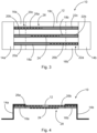
- the 1 shows a fastening system 100 for a sanitary installation.
- the fastening system 100 comprises a fastening device 10 and two sanitary engineering components 102a, 102b fastened to the fastening device 10.
- the sanitary engineering components 102a, 102b are designed as fluid connections, namely as water connections.
- the sanitary engineering component 102a is a hot water connection.
- Sanitary component 102b is a cold water connection.
- the fastening device 10 has a carrier body 12 to which the sanitary engineering components 102a, 102b are fastened.
- the carrier body 12 is a carrier plate made of aluminum.
- the carrier plate 12 is designed as a grooved plate with a plurality, namely three, spaced apart and parallel grooves 18a-18c.
- Adjusting clamping bodies 26a, 26b of an adjusting mechanism 28 are arranged in the grooves 18a, 18c.
- the grooves 18a-18c of the carrier body 12 are designed as T-grooves.
- the adjustment clamping bodies 26a, 26b are elongated T-nuts.
- the sanitary engineering components 102a, 102b are fastened to a fastening clamp body 24.
- the mounting clip body 24 is also an elongated T-nut.
- the sanitary engineering components 102a, 102b can also be fastened to different fastening clamp bodies.
- the adjustment clamping body 26a is connected to a mounting body 14a via a clamping body receiving member 16a.
- the adjustment clamping body 26b is connected to the mounting body 14b via a clamping body receiving member 16b.
- the adjustment clamping bodies 26a, 26b are clamped to the clamping body receiving members 16a, 16b.
- the sprag receiving members 16a, 16b also have three grooves 20a-20c, 22a-22c running parallel to one another and spaced apart from one another, with the grooves 20a-20c, 22a-22c being designed as T-grooves. Accordingly, the clamping body receiving members 16a, 16b are also designed as grooved plates.
- the mounting bodies 14a, 14b are each set up to be attached to a drywall profile 104a, 104b of a stud frame.
- the 2 shows that the distance between the mounting bodies 14a, 14b can be changed by the adjustment mechanism 28, which includes the grooves 18a, 18c and the adjustment clamping bodies 26a, 26b. Furthermore, the distance between the mounting body 14a and the carrier body 12 and the distance between the mounting body 14b and the carrier body 12 can also be changed via the adjusting mechanism.
- the fastening device 10 can thus be adapted to the installation dimensions specified by the stud frame. Furthermore, the fastening device 10 allows the sanitary engineering components 102a, 102b to be positioned relative to the framework.
- the mounting bodies 14a, 14b are arranged opposite one another and on opposite sides of the carrier body 12.
- the drywall profiles 104a, 104b of the stud frame are transversely spaced from each other. The distance in the transverse direction between the drywall profiles 104a, 104b can be set on the fastening device 10 by means of the adjustment mechanism 28 without great effort.
- the distance between the assembly bodies 14a, 14b can be changed in the transverse direction by means of the adjustment mechanism 28.
- the distance between the mounting bodies can also be changed in one or more other spatial directions.
- a depth offset of the drywall profiles 104a, 104b can also be compensated for, for example.
- a height distance between assembly points of the dry construction profiles 104a, 104b can also be compensated for by a corresponding adjustability.
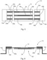
- FIGS 3 and 4 show a fastening device 10 in which the minimum distance between the mounting bodies 14a, 14b is set.
- FIGS 5 and 6 show the same fastening device 10, wherein the distance between the mounting bodies 14a, 14b has been increased by the adjustment mechanism 28.
- the adjustment mechanism 28 includes a rail system with two adjustment clamping bodies 26a, 26b and grooves 18a-18c, 20a-20c, 22a-22c.
- the adjustment clamping bodies 26a, 26b are elongated T-nuts.
- the grooves 18a-18c, 20a-20c, 22a-22c are T-grooves.
- the adjusting clamping body 26a can be displaced and clamped in the grooves 18c, 20c, 22c.
- the adjustment clamping body 26b can be displaced and clamped in the grooves 18a, 20a, 22a.
- the adjustment clamping bodies 26a, 26b could also be inserted into the grooves 18b, 20b, 22b.
- the adjustment clamping bodies 26a, 26b each have at least two clamping members, via which a clamping effect can be generated in the respective grooves 18a-18c, 20a-20c, 22a-22c.
- the clamping members can be screws, for example, which are screwed into threaded holes in the adjustment clamping bodies 26a, 26b.
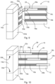
- the Figures 7 and 8 show that the sanitary engineering components 102a, 102b can be fastened at different positions on the carrier body 12 or even at a distance from the carrier body.
- the support body 12 has a displacement system, via which the technical sanitary components 102a, 102b can be displaced on the support body 12.
- the displacement system is designed as a rail system with at least one fastening clamp body 24 and a groove 18b.
- the sanitary engineering components 102a, 102b are attached to the fastening clamp body 24, the fastening clamp body 24 being displaceable and clampable in the groove 18b.
- the fastening clamp body 24 has at least one clamping member, by means of which a clamping effect can be generated.
- the clamping member can be a screw which is screwed into a threaded hole of the fastening clamp body 24 .
- the attachment clamp body 24 is designed as a T-nut in this embodiment, with the groove 18b being a T-groove.
- the carrier body 12 thus includes grooves 18a, 18c, which are used by the adjustment mechanism 28 and a groove 18b, which is used by the displacement system for the sanitary components 102a, 102b.
- the 9 shows a fastening device 10 in which the distance between the mounting body 14a and the carrier body 12 can be changed in two spatial directions.
- the adjustment mechanism 28 has an adjustment clamping body 26a, which is angled.
- the angled adjustment clamping body 26 has a bending angle ⁇ of 90 degrees.
- the bending angle ⁇ can also have a different value.
- the sprag receiving member 16a can be moved along a first leg of the adjustment sprag 26a.
- the carrier body 12 can be adjusted along a second leg of the adjustment clamping body 26a.
- the distance between the mounting body 14a and the carrier body 12 in the transverse direction and perpendicular to the transverse direction can be adjusted by moving the clamping body receiving element 16a and the carrier body 12 along the legs of the adjustment clamping body 26a. In this way, in addition to adjusting the width of the fastening device 10, the installation depth of the one or more sanitary components 102a, 102b attached to the support body 12 can be adjusted at the same time.
- the 10 shows that the assembly body 14a is attached to the attachment points 30a, 30b on the drywall profile 104a.
- the dry construction profile 104a is a CW profile.
- the mounting body 14a is crimped at the attachment points 30a, 30b with the drywall profile 104a.
- the 11 shows that the attachment can also take place at the illustrated attachment points 30a, 30b.
- the drywall profile 104b is a UA profile and the mounting body 14a is screwed or riveted to the drywall profile 104b.
- the 12 and 13 12 show that sprag receiving member 16a may be connected to mounting body 14a at attachment points 32a, 32b.
- the mounting body 14a and the Clamp body receiving member 16a screwed together, riveted or glued.
Description
Die Erfindung betrifft eine Befestigungsvorrichtung für eine sanitärtechnische Anlage, mit einem Trägerkörper, an welchem zumindest ein sanitärtechnisches Bauteil oder zumindest eine sanitärtechnische Baugruppe befestigbar ist, einem ersten Montagekörper und einem von dem ersten Montagekörper beabstandeten zweiten Montagekörper, wobei der erste Montagekörper mit dem Trägerkörper verbunden und dazu eingerichtet ist, an einem ersten Trockenbauprofil eines Ständerwerks befestigt zu werden, und der zweite Montagekörper mit dem Trägerkörper verbunden und dazu eingerichtet ist, an einem von dem ersten Trockenbauprofil beabstandeten zweiten Trockenbauprofil des Ständerwerks befestigt zu werden, und einer Verstellmechanik, mittels welcher der Abstand zwischen dem Trägerkörper und dem ersten und zweiten Montagekörper und der Abstand zwischen dem ersten Montagekörper und dem zweiten Montagekörper veränderbar ist.The invention relates to a fastening device for a sanitary system, with a carrier body, to which at least one sanitary engineering component or at least one sanitary engineering assembly can be fastened, a first assembly body and a second assembly body spaced apart from the first assembly body, the first assembly body being connected to the carrier body and is designed to be attached to a first drywall profile of a stud frame, and the second assembly body is connected to the carrier body and set up to be attached to a second drywall profile of the stud frame spaced apart from the first drywall profile, and an adjustment mechanism by means of which the distance between the carrier body and the first and second mounting body and the distance between the first mounting body and the second mounting body is variable.
Ferner betrifft die Erfindung ein Befestigungssystem für eine sanitärtechnische Anlage, mit einer Befestigungsvorrichtung und zumindest einem an der Befestigungsvorrichtung befestigten sanitärtechnischen Bauteil oder zumindest einer an der Befestigungsvorrichtung befestigten sanitärtechnische Baugruppe.Furthermore, the invention relates to a fastening system for a sanitary installation, with a fastening device and at least one sanitary technical component fastened to the fastening device or at least one sanitary technical subassembly fastened to the fastening device.
Darüber hinaus betrifft die Erfindung ein Verfahren zum Befestigen eines Montagekörpers einer Befestigungsvorrichtung für eine sanitärtechnische Anlage an einem Trockenbauprofil eines Ständerwerks.In addition, the invention relates to a method for fastening a mounting body of a fastening device for a sanitary installation to a dry construction profile of a stud frame.
Bei der sanitärtechnischen Ausstattung von Gebäuden ist es regelmäßig erforderlich, sanitärtechnische Bauteile oder sanitärtechnische Baugruppen, wie beispielsweise Fluidanschlüsse, an einem vorhandenen Trockenbau-Ständerwerk zu befestigen. Entsprechende Ständerwerke bestehen regelmäßig aus mehreren voneinander beabstandeten Trockenbauprofilen, wobei die Trockenbauprofile üblicherweise zur Fixierung der Befestigungsvorrichtung verwendet werden.In the sanitary equipment of buildings, it is regularly necessary sanitary components or sanitary assemblies, such as for example, fluid connections to be attached to an existing drywall stud frame. Corresponding stud frames regularly consist of a plurality of drywall profiles spaced apart from one another, with the drywall profiles usually being used to fix the fastening device.
Als Befestigungsvorrichtung werden im Stand der Technik beispielsweise Holzplatten eingesetzt, an welchen die zu befestigenden sanitärtechnischen Bauteile oder sanitärtechnischen Baugruppen angeschraubt werden. Die Holzplatten sind mit Montagekörpern auszustatten, welche dann an den Trockenbauprofilen des Ständerwerks zu befestigen sind.In the prior art, for example, wooden panels are used as fastening devices, to which the sanitary engineering components or sanitary engineering assemblies to be fastened are screwed. The wooden panels are to be equipped with mounting bodies, which are then to be attached to the drywall profiles of the stud frame.
Andere Befestigungsvorrichtungen sind beispielsweise aus den Druckschriften
Da die Trockenbauprofile von Ständerwerken unterschiedliche Abstände zueinander aufweisen können, ist es regelmäßig erforderlich, die Holzplattenkonstruktion individuell auf das vorhandene Ständerwerk anzupassen, sodass die Befestigungsvorrichtung an einem oder mehreren Trockenbauprofilen befestigt und gleichzeitig die beabsichtigte Position des sanitärtechnischen Bauteils oder der sanitärtechnischen Baugruppe realisiert werden kann.Since the drywall profiles of stud frames can have different distances from each other, it is regularly necessary to individually adapt the wooden panel construction to the existing stud frame so that the fastening device can be attached to one or more drywall profiles and at the same time the intended position of the sanitary component or sanitary technical assembly can be realized.
Die individuelle Anpassung der im Stand der Technik bekannten Befestigungsvorrichtungen an unterschiedliche Ständerwerkkonstruktionen ist bisher äußerst zeit- und somit auch kostenaufwändig. Die Installation von sanitärtechnischen Anlagen wird hierdurch erheblich verzögert und es kommt zu hohen Montagekosten.The individual adaptation of the fastening devices known in the prior art to different stand constructions has hitherto been extremely time-consuming and therefore also costly. This considerably delays the installation of sanitary facilities and results in high installation costs.
Die der Erfindung zugrundeliegende Aufgabe besteht somit darin, die Anpassbarkeit von Befestigungsvorrichtungen an unterschiedliche Trockenbau-Ständerwerke zu verbessern.The object on which the invention is based is therefore to improve the adaptability of fastening devices to different drywall posts.
Die Aufgabe wird gelöst durch eine Befestigungsvorrichtung der eingangs genannten Art, wobei der Trägerkörper als Nutenplatte mit mehreren Nuten ausgebildet ist und die Verstellmechanik ein Schienensystem mit zwei Verstellklemmkörpern umfasst, wobei der erste Montagekörper mit einem ersten Verstellklemmkörper verbunden ist und der erste Verstellklemmkörper in einer ersten Nut des Trägerkörpers verschiebbar und verklemmbar ist, und der zweite Montagekörper mit einem zweiten Verstellklemmkörper verbunden ist und der zweite Verstellklemmkörper in einer zweiten Nut des Trägerkörpers verschiebbar und verklemmbar ist.The object is achieved by a fastening device of the type mentioned at the outset, the carrier body being designed as a grooved plate with a number of grooves and the adjustment mechanism being a rail system with two comprises adjustment clamping bodies, wherein the first mounting body is connected to a first adjustment clamping body and the first adjustment clamping body can be displaced and clamped in a first groove of the carrier body, and the second mounting body is connected to a second adjustment clamping body and the second adjustment clamping body can be displaced in a second groove of the carrier body and can be jammed.
Mittels der Verstellmechanik kann eine Anpassung der Befestigungsvorrichtung an die von dem Ständerwerk vorgegebenen Einbaumaße erfolgen. Ferner ermöglicht die erfindungsgemäße Befestigungsvorrichtung ein Positionieren des sanitärtechnischen Bauteils oder der sanitärtechnischen Baugruppe relativ zum Ständerwerk, sodass eine beabsichtigte Bauteilposition oder Baugruppenposition mit einem äußerst geringen Zeit- und somit auch Kostenaufwand realisierbar ist.By means of the adjustment mechanism, the fastening device can be adapted to the installation dimensions specified by the stud frame. Furthermore, the fastening device according to the invention enables positioning of the sanitary engineering component or the sanitary engineering assembly group relative to the stud frame, so that an intended component position or assembly group position can be realized with an extremely low expenditure of time and thus also cost.
An dem Trägerkörper können auch mehrere sanitärtechnische Bauteile oder sanitärtechnische Baugruppen befestigbar sein. Die sanitärtechnischen Bauteile oder die sanitärtechnischen Baugruppen können entweder direkt oder über ein oder mehrere Zwischenglieder, wie beispielsweise Wandscheiben, Gehäuseteile oder ergänzende Trägerelemente, an dem Trägerkörper befestigt werden. Die sanitärtechnischen Bauteile können beispielsweise mit einer Aufputzarmatur verbunden werden. Die sanitärtechnischen Bauteile oder die sanitärtechnischen Baugruppen können beispielsweise Fluidanschlüsse oder Fluidleitungen sein oder umfassen. Insbesondere können die sanitärtechnischen Bauteile oder die sanitärtechnischen Baugruppen Ver- oder Entsorgungsanschlüsse sein oder umfassen. Insbesondere sind oder umfassen die sanitärtechnischen Bauteile oder die sanitärtechnischen Baugruppen Frischwasser-, Abwasser- oder Luftanschlüsse. Ferner können die sanitärtechnischen Bauteile oder die sanitärtechnischen Baugruppen Frischwasser-, Abwasser- oder Luftleitungen sein oder umfassen. Das sanitärtechnische Bauteil oder die sanitärtechnische Baugruppe kann auch ein Lüftergehäuse sein oder umfassen.Several sanitary engineering components or sanitary engineering assemblies can also be fastened to the carrier body. The sanitary engineering components or the sanitary engineering assemblies can be attached to the carrier body either directly or via one or more intermediate members, such as wall plates, housing parts or additional carrier elements. The sanitary components can be connected to an exposed fitting, for example. The sanitary engineering components or the sanitary engineering assemblies can be or include, for example, fluid connections or fluid lines. In particular, the sanitary engineering components or the sanitary engineering assemblies can be or include supply or disposal connections. In particular, the sanitary engineering components or the sanitary engineering assemblies are or include fresh water, waste water or air connections. Furthermore, the sanitary engineering components or the sanitary engineering assemblies can be or include fresh water, waste water or air lines. The sanitary engineering component or the sanitary engineering assembly can also be or include a fan housing.
Der Trägerkörper kann eine Trägerplatte sein. Die Trägerplatte kann beispielsweise aus Metall, insbesondere aus Aluminium, ausgebildet sein. Der zumindest eine Montagekörper kann dazu eingerichtet sein, mit einem Trockenbauprofil eines Ständerwerks vercrimpt, verschraubt und/oder vernietet zu werden. Der zumindest eine Montagekörper kann ein Z-Profil oder ein L-Profil aufweisen.The carrier body can be a carrier plate. The support plate can be made of metal, for example, in particular aluminum. The at least one mounting body can be set up with a Drywall profile of a stud frame to be crimped, screwed and/or riveted. The at least one assembly body can have a Z-profile or an L-profile.
Die sanitärtechnische Anlage, in welcher die erfindungsgemäße Befestigungsvorrichtung eingesetzt werden kann, kann beispielsweise der stofflichen Versorgung, etwa mit Wasser, Luft oder Gas, und/oder der Entsorgung von Abwasser dienen.The sanitary installation, in which the fastening device according to the invention can be used, can be used, for example, to supply materials, such as water, air or gas, and/or to dispose of waste water.
Erfindungsgemäß weist die Befestigungsvorrichtung einen ersten Montagekörper und einen von dem ersten Montagekörper beabstandeten zweiten Montagekörper auf. Der erste Montagekörper ist mit dem Trägerkörper verbunden und dazu eingerichtet, an einem ersten Trockenbauprofil eines Ständerwerks befestigt zu werden. Der zweite Montagekörper ist mit dem Trägerkörper verbunden und dazu eingerichtet, an einem von dem ersten Trockenbauprofil beabstandeten zweiten Trockenbauprofil des Ständerwerks befestigt zu werden. Vorzugsweise ist der Abstand zwischen dem ersten Montagekörper und dem zweiten Montagekörper mittels der Verstellmechanik veränderbar. Vorzugsweise sind der erste und der zweite Montagekörper gegenüberliegend und/oder auf gegenüberliegenden Seiten des Trägerkörpers angeordnet. Der Abstand zwischen dem ersten und dem zweiten Montagekörper kann auf den Abstand zwischen dem ersten und dem zweiten Trockenbauprofil des Ständerwerks angepasst werden, an welchem die Montagekörper befestigt werden sollen. Vorzugsweise ist der Abstand zwischen dem ersten Montagekörper und dem Trägerkörper mittels der Verstellmechanik veränderbar. Vorzugsweise ist der Abstand zwischen dem zweiten Montagekörper und dem Trägerkörper mittels der Verstellmechanik veränderbar.According to the invention, the fastening device has a first mounting body and a second mounting body spaced apart from the first mounting body. The first assembly body is connected to the carrier body and set up to be attached to a first dry construction profile of a stud frame. The second assembly body is connected to the carrier body and set up to be fastened to a second dry construction profile of the stud frame spaced apart from the first dry construction profile. The distance between the first mounting body and the second mounting body can preferably be changed by means of the adjustment mechanism. The first and the second assembly body are preferably arranged opposite one another and/or on opposite sides of the carrier body. The distance between the first and the second mounting body can be adjusted to the distance between the first and the second drywall profile of the stud frame to which the mounting body is to be attached. The distance between the first assembly body and the carrier body can preferably be changed by means of the adjustment mechanism. The distance between the second assembly body and the carrier body can preferably be changed by means of the adjustment mechanism.
In einer weiteren bevorzugten Ausführungsform der erfindungsgemäßen Befestigungsvorrichtung ist der Abstand zwischen dem ersten Montagekörper und dem zweiten Montagekörper mittels der Verstellmechanik in eine oder mehrere Raumrichtungen veränderbar. Der Abstand zwischen dem ersten Montagekörper und dem zweiten Montagekörper kann beispielsweise in Querrichtung veränderbar sein, sodass über die Abstandsänderung die Breite der Befestigungsvorrichtung einstellbar ist. Ferner kann der Abstand zwischen dem ersten Montagekörper und dem zweiten Montagekörper senkrecht zur Querrichtung veränderbar sein, sodass über eine Abstandsveränderung ein Tiefenversatz der zur Befestigung verwendeten Trockenbauprofile des Ständerwerks ausgeglichen werden kann. Außerdem kann der Höhenabstand zwischen dem ersten Montagekörper und dem zweiten Montagekörper veränderbar sein, sodass ein Höhenversatz der Montagestellen an den Trockenbauprofilen, an welchen die Montagekörper befestigt werden sollen, ausgeglichen werden kann. Es kann auch der Abstand zwischen dem ersten Montagekörper und der Trägerplatte und/oder der Abstand zwischen dem zweiten Montagekörper und/oder der Trägerplatte mittels der Verstellmechanik in eine oder mehrere Raumrichtungen veränderbar sein. Der Abstand zwischen dem ersten Montagekörper und der Trägerplatte und/oder zwischen dem zweiten Montagekörper und der Trägerplatte kann senkrecht zur Querrichtung veränderbar sein, sodass die Einbautiefe des zumindest einen sanitärtechnischen Bauteils oder der zumindest einen sanitärtechnischen Baugruppe über die Befestigungsvorrichtung einstellbar ist.In a further preferred embodiment of the fastening device according to the invention, the distance between the first mounting body and the second mounting body can be changed in one or more spatial directions by means of the adjustment mechanism. The distance between the first mounting body and the second mounting body can be changed, for example, in the transverse direction, so that the width of the change in distance Fastening device is adjustable. Furthermore, the distance between the first mounting body and the second mounting body can be changed perpendicularly to the transverse direction, so that a depth offset of the drywall profiles of the stud frame used for fastening can be compensated for by changing the distance. In addition, the vertical distance between the first assembly body and the second assembly body can be variable, so that a height offset of the assembly points on the drywall profiles to which the assembly body is to be attached can be compensated. The distance between the first assembly body and the carrier plate and/or the distance between the second assembly body and/or the carrier plate can also be variable in one or more spatial directions by means of the adjustment mechanism. The distance between the first mounting body and the support plate and/or between the second mounting body and the support plate can be changeable perpendicularly to the transverse direction, so that the installation depth of the at least one sanitary engineering component or the at least one sanitary engineering assembly group can be adjusted via the fastening device.
Die Verstellmechanik der Befestigungsvorrichtung ist vorzugsweise reversibel und zerstörungsfrei lösbar ausgebildet, sodass über die Verstellmechanik eingestellte Abstände nachträglich korrigiert werden können. Insbesondere bei einer unbeabsichtigten Fehleinstellung des Abstands zwischen dem ersten Montagekörper und dem zweiten Montagekörper erlaubt dies eine praxistaugliche und schnelle nachträgliche Anpassung der Konfiguration der Befestigungsvorrichtung.The adjustment mechanism of the fastening device is preferably designed to be reversible and detachable without destroying it, so that distances set via the adjustment mechanism can be subsequently corrected. In particular, in the event of an unintentional misadjustment of the distance between the first mounting body and the second mounting body, this allows a practical and quick subsequent adjustment of the configuration of the fastening device.
In einer weiteren bevorzugten Ausführungsform der erfindungsgemäßen Befestigungsvorrichtung ist das zumindest eine sanitärtechnische Bauteil oder die zumindest eine sanitärtechnische Baugruppe an unterschiedlichen Positionen an dem Trägerkörper befestigbar. Der Trägerkörper kann beispielsweise Befestigungspositionen für eine oder mehrere sanitärtechnische Bauteile oder sanitärtechnische Baugruppen vorgeben.In a further preferred embodiment of the fastening device according to the invention, the at least one sanitary engineering component or the at least one sanitary engineering assembly group can be fastened at different positions on the carrier body. The carrier body can, for example, specify fastening positions for one or more sanitary engineering components or sanitary engineering assemblies.
In einer Weiterbildung der erfindungsgemäßen Befestigungsvorrichtung weist der Trägerkörper ein Verschiebesystem auf, über welches das zumindest eine sanitärtechnische Bauteil oder die zumindest eine sanitärtechnische Baugruppe an dem Trägerkörper verschiebbar ist. Vorzugsweise ist das sanitärtechnische Bauteil oder die sanitärtechnische Baugruppe über das Verschiebesystem in Querrichtung verschiebbar. Alternativ oder zusätzlich kann über das Verschiebesystem auch eine Höhenverschiebbarkeit umgesetzt werden. Über das Verschiebesystem lässt sich der Abstand des einen oder der mehreren sanitärtechnischen Bauteile oder sanitärtechnischen Baugruppen von den zur Befestigung eingesetzten Montagekörpern einstellen.In a development of the fastening device according to the invention, the carrier body has a displacement system, via which the at least one sanitary engineering component or the at least one sanitary engineering assembly group can be displaced on the carrier body. The sanitary engineering component or the sanitary engineering assembly can preferably be displaced in the transverse direction via the displacement system. Alternatively or additionally, the displacement system can also be used to adjust the height. The distance between the one or more sanitary engineering components or sanitary engineering assemblies and the mounting bodies used for attachment can be adjusted via the displacement system.
In einer weiteren bevorzugten Ausführungsform der erfindungsgemäßen Befestigungsvorrichtung ist das Verschiebesystem als Schienensystem mit zumindest einem Befestigungsklemmkörper und zumindest einer Nut ausgebildet. Das zumindest eine sanitärtechnische Bauteil oder die zumindest eine sanitärtechnische Baugruppe ist an dem Befestigungsklemmkörper befestigbar und der Befestigungsklemmkörper ist in der Nut verschiebbar und/oder verklemmbar. Der Befestigungsklemmkörper kann beispielsweise eine oder mehrere Gewindebohrungen zum Anschrauben des sanitärtechnischen Bauteils oder der sanitärtechnischen Baugruppe aufweisen. Die Nut des als Schienensystem ausgebildeten Verschiebesystems kann eine T-Nut sein. Der Befestigungsklemmkörper kann eine Gleitmutter, insbesondere eine längliche Mutter bzw. ein länglicher Nutenstein für eine T-Nut, sein. Das als Schienensystem ausgebildete Verschiebesystem kann auch mehrere Nuten aufweisen, wobei die mehreren Nuten beispielsweise beabstandet voneinander angeordnet sind und/oder parallel zueinander verlaufen.In a further preferred embodiment of the fastening device according to the invention, the displacement system is designed as a rail system with at least one fastening clamp body and at least one groove. The at least one sanitary engineering component or the at least one sanitary engineering assembly can be fastened to the fastening clamp body and the fastening clamp body can be displaced and/or clamped in the groove. The fastening clamp body can have, for example, one or more threaded holes for screwing on the sanitary engineering component or the sanitary engineering assembly. The groove of the sliding system designed as a rail system can be a T-groove. The fastening clamp body can be a sliding nut, in particular an elongated nut or an elongated sliding block for a T-slot. The displacement system designed as a rail system can also have a plurality of grooves, with the plurality of grooves being arranged at a distance from one another and/or running parallel to one another.
Es ist ferner eine Befestigungsvorrichtung vorteilhaft, bei welcher die Verstellmechanik ein Schienensystem mit zumindest einem Verstellklemmkörper und zumindest einer Nut umfasst. Der zumindest eine Montagekörper ist mit dem Verstellklemmkörper verbunden und der Verstellklemmkörper ist in der Nut verschiebbar und/oder verklemmbar. Wenn die Befestigungsvorrichtung zwei Montagekörper aufweist, sind die zwei Montagekörper vorzugsweise jeweils über das Schienensystem verschiebbar. Die Nut des Schienensystems der Verstellmechanik kann eine T-Nut sein. Der Verstellklemmkörper kann eine Gleitmutter, insbesondere eine längliche Mutter bzw. ein länglicher Nutenstein für eine T-Nut, sein. Das Schienensystem der Verstellmechanik kann auch mehrere Nuten aufweisen, wobei die mehreren Nuten beabstandet zueinander angeordnet und/oder parallel zueinander verlaufen können.A fastening device is also advantageous in which the adjustment mechanism comprises a rail system with at least one adjustment clamping body and at least one groove. The at least one assembly body is connected to the adjustment clamping body and the adjustment clamping body can be displaced and/or clamped in the groove. If the fastening device has two mounting bodies, the two mounting bodies can preferably each be slid over the rail system. The groove of the rail system Adjustment mechanism can be a T-slot. The adjustable clamping body can be a slide nut, in particular an elongated nut or an elongated sliding block for a T-slot. The rail system of the adjusting mechanism can also have a number of grooves, with the number of grooves being arranged at a distance from one another and/or being able to run parallel to one another.
Es ist außerdem eine Befestigungsvorrichtung bevorzugt, bei welcher der zumindest eine Montagekörper an einem Klemmkörperaufnahmeglied befestigt ist und der Verstellklemmkörper an dem Klemmkörperaufnahmeglied fixiert, insbesondere verklemmt ist. Das Klemmkörperaufnahmeglied kann eine Nut, beispielsweise eine T-Nut aufweisen, in welcher der Verstellklemmkörper verklemmt ist. Das Klemmkörperaufnahmeglied kann eine Nutenplatte sein. Der Montagekörper kann mit dem Klemmkörperaufnahmeglied stoffschlüssig, formschlüssig und/oder kraftschlüssig verbunden sein. Insbesondere ist der Montagekörper mit dem Klemmkörperaufnahmeglied verschraubt und/oder verklebt.A fastening device is also preferred in which the at least one assembly body is fastened to a clamping body receiving member and the adjustment clamping body is fixed, in particular clamped, to the clamping body receiving member. The clamping body receiving member can have a groove, for example a T-groove, in which the adjustment clamping body is clamped. The sprag receiving member may be a grooved plate. The mounting body can be connected to the clamping body receiving member in a materially bonded, form-fitting and/or non-positive manner. In particular, the assembly body is screwed and/or glued to the clamping body receiving member.
In einer Weiterbildung der erfindungsgemäßen Befestigungsvorrichtung wird ein erster Montagekörper zur Fixierung an einem ersten Klemmkörperaufnahmeglied mittels einer ersten Stabilisierungsplatte flächig gegen das erste Klemmkörperaufnahmeglied gedrückt. Ein zweiter Montagekörper wird zur Fixierung an einem zweiten Klemmkörperaufnahmeglied mittels einer zweiten Stabilisierungsplatte flächig gegen das zweite Klemmkörperaufnahmeglied gedrückt. Durch die Verwendung von Stabilisierungsplatten wird die Stabilität und Belastbarkeit der Befestigungsvorrichtung, insbesondere die Verwindungssteifigkeit in den Übergangsbereichen zwischen den Montagekörpern und den Klemmkörperaufnahmegliedern, erheblich gesteigert.In a further development of the fastening device according to the invention, a first mounting body is pressed flat against the first clamping body receiving member by means of a first stabilizing plate for fixing to a first clamping body receiving member. A second mounting body is pressed flat against the second clamping body receiving member by means of a second stabilizing plate for fixing to a second clamping body receiving member. The use of stabilizing plates considerably increases the stability and resilience of the fastening device, in particular the torsional rigidity in the transition areas between the mounting bodies and the clamping body receiving members.
In einer weiteren bevorzugten Ausführungsform der erfindungsgemäßen Befestigungsvorrichtung umfasst der Trägerkörper zumindest eine Nut des Verschiebesystems. Das Verschiebesystem und die Verstellmechanik können auch die gleichen Nuten nutzen. Somit kann in einer Nut sowohl ein Befestigungsklemmkörper als auch ein Verstellklemmkörper befestigt, insbesondere verklemmt, sein.In a further preferred embodiment of the fastening device according to the invention, the carrier body comprises at least one groove of the displacement system. The displacement system and the adjustment mechanism can also use the same grooves. Thus, both a fastening clamp body and an adjustment clamp body can be fastened, in particular clamped, in a groove.
Es ist außerdem eine erfindungsgemäße Befestigungsvorrichtung vorteilhaft, bei welcher die Nuten der Nutenplatte parallel zueinander verlaufen. Der Trägerkörper kann eine T-Nut-Schiene sein.A fastening device according to the invention is also advantageous in which the grooves of the grooved plate run parallel to one another. The carrier body can be a T-slot rail.
Erfindungsgemäß umfasst die Verstellmechanik ein Schienensystem mit zwei Verstellklemmkörpern, wobei ein erster Montagekörper mit einem ersten Verstellklemmkörper verbunden ist und der erste Verstellklemmkörper in einer ersten Nut des Trägerkörpers verschiebbar und/oder verklemmbar ist. Ein zweiter Montagekörper ist mit einem zweiten Verstellklemmkörper verbunden und der zweite Verstellklemmkörper ist in einer zweiten Nut des Trägerkörpers verschiebbar und/oder verklemmbar. Dadurch, dass die Verstellklemmkörper in verschiedenen Nuten des Trägerkörpers eingesetzt sind, können die einzelnen Verstellklemmkörper länger ausgeführt werden, ohne dass sich die Verstellklemmkörper in der derselben Nut gegenseitig blockieren. Insofern wird durch die längeren Verstellklemmkörper der einstellbare Abstand der Montagekörper bzw. die einstellbare Breite der Befestigungsvorrichtung erheblich erhöht. Die Befestigungsvorrichtung ist somit wesentlich universeller einsetzbar. Darüber hinaus wird die von den Verstellklemmkörpern aufgenommene Belastung über zweite verschiedene Nuten des Trägerkörpers übertragen, sodass die mechanische Belastung des Trägerkörpers reduziert wird.According to the invention, the adjustment mechanism comprises a rail system with two adjustment clamping bodies, a first mounting body being connected to a first adjustment clamping body and the first adjustment clamping body being displaceable and/or clampable in a first groove of the carrier body. A second mounting body is connected to a second adjustment clamping body and the second adjustment clamping body can be displaced and/or clamped in a second groove of the carrier body. Because the adjustment clamping bodies are inserted in different grooves of the carrier body, the individual adjustment clamping bodies can be made longer without the adjustment clamping bodies blocking one another in the same groove. In this respect, the adjustable distance between the mounting bodies or the adjustable width of the fastening device is increased considerably by the longer adjusting clamping bodies. The fastening device can thus be used much more universally. In addition, the load absorbed by the adjustment clamping bodies is transmitted via two different grooves in the carrier body, so that the mechanical load on the carrier body is reduced.
In einer anderen Ausführungsform der erfindungsgemäßen Befestigungsvorrichtung ist der Befestigungsklemmkörper des Verschiebesystems in einer dritten Nut des Trägerkörpers verschiebbar und/oder verklemmbar. Die der Verstellmechanik zugeordnete erste und zweite Nut des Trägerkörpers sowie die dem Verschiebesystem zugeordnete dritte Nut des Trägerkörpers können auf der gleichen Seite oder auf verschiedenen Seiten des Trägerkörpers verlaufen. Vorzugsweise verläuft die der Verstellmechanik zugeordnete erste und die zweite Nut auf der Rückseite des Trägerkörpers und die dem Verschiebesystem zugeordnete dritte Nut verläuft auf der Vorderseite des Trägerkörpers.In another embodiment of the fastening device according to the invention, the fastening clamping body of the displacement system can be displaced and/or clamped in a third groove of the carrier body. The first and second grooves of the carrier body assigned to the adjustment mechanism and the third groove of the carrier body assigned to the displacement system can run on the same side or on different sides of the carrier body. Preferably, the first and second grooves assigned to the adjustment mechanism run on the rear side of the carrier body and the third groove assigned to the displacement system runs on the front side of the carrier body.
In einer anderen bevorzugten Ausführungsform der erfindungsgemäßen Befestigungsvorrichtung sind der Trägerkörper und der zumindest eine Montagekörper zerstörungsfrei und reversibel lösbar miteinander verbunden. Die zerstörungsfreie und reversibel lösbare Verbindung zwischen dem Trägerkörper und dem zumindest einen Montagekörper erlaubt eine nachträgliche Korrektur der Konfiguration der Befestigungsvorrichtung.In another preferred embodiment of the fastening device according to the invention, the carrier body and the at least one Assembly body non-destructively and reversibly detachably connected to each other. The non-destructive and reversibly detachable connection between the carrier body and the at least one assembly body allows subsequent correction of the configuration of the fastening device.
Die der Erfindung zugrundeliegende Aufgabe wird ferner durch ein Befestigungssystem der eingangs genannten Art gelöst, wobei die Befestigungsvorrichtung des erfindungsgemäßen Befestigungssystems nach einer der vorstehend beschriebenen Ausführungsformen ausgebildet ist. Hinsichtlich der Vorteile und Modifikationen des erfindungsgemäßen Befestigungssystems wird somit zunächst auf die Vorteile und Modifikationen der erfindungsgemäßen Befestigungsvorrichtung verwiesen.The object on which the invention is based is also achieved by a fastening system of the type mentioned at the beginning, wherein the fastening device of the fastening system according to the invention is designed according to one of the embodiments described above. With regard to the advantages and modifications of the fastening system according to the invention, reference is first made to the advantages and modifications of the fastening device according to the invention.
In einer bevorzugten Ausführungsform des erfindungsgemäßen Befestigungssystems ist das zumindest eine sanitärtechnische Bauteil als Fluidanschluss ausgebildet oder die zumindest eine sanitärtechnische Baugruppe umfasst einen Fluidanschluss. Der Fluidanschluss kann beispielsweise ein Flüssigkeitsanschluss, insbesondere ein Wasseranschluss, sein.In a preferred embodiment of the fastening system according to the invention, the at least one sanitary component is designed as a fluid connection or the at least one sanitary component includes a fluid connection. The fluid connection can, for example, be a liquid connection, in particular a water connection.
Die der Erfindung zugrundeliegende Aufgabe wird ferner durch ein Verfahren der eingangs genannten Art gelöst, wobei der Montagekörper an einem Befestigungspunkt mit dem Trockenbauprofil vercrimpt wird. Die Befestigungsvorrichtung ist erfindungsgemäß nach einer der vorstehenden Ausführungsformen ausgebildet. Hinsichtlich der Vorteile und Modifikationen des erfindungsgemäßen Verfahrens wird somit auf die Vorteile und Modifikationen der erfindungsgemäßen Befestigungsvorrichtung verwiesen.The object on which the invention is based is also achieved by a method of the type mentioned at the outset, in which the assembly body is crimped to the drywall profile at a fastening point. According to the invention, the fastening device is designed according to one of the above embodiments. With regard to the advantages and modifications of the method according to the invention, reference is therefore made to the advantages and modifications of the fastening device according to the invention.
Nachfolgend werden bevorzugte Ausführungsformen der Erfindung unter Bezugnahme auf die beiliegenden Zeichnungen näher erläutert und beschrieben. Dabei zeigen:
- Fig. 1
- ein Ausführungsbeispiel des erfindungsgemäßen Befestigungssystems in einer perspektivischen Darstellung;
- Fig. 2
- ein Ausführungsbeispiel der erfindungsgemäßen Befestigungsvorrichtung in einer schematischen Darstellung;
- Fig. 3
- ein Ausführungsbeispiel der erfindungsgemäßen Befestigungsvorrichtung in einer schematischen Frontansicht in einem ersten Zustand;
- Fig. 4
- die in der
Fig. 3 abgebildete Befestigungsvorrichtung in einer schematischen Draufsicht in dem ersten Zustand; - Fig. 5
- die in der
Fig. 3 abgebildete Befestigungsvorrichtung in einer schematischen Frontansicht in einem zweiten Zustand; - Fig. 6
- die in der
Fig. 3 abgebildete Befestigungsvorrichtung in einer schematischen Draufsicht in dem zweiten Zustand; - Fig. 7
- ein weiteres Ausführungsbeispiel des erfindungsgemäßen Befestigungssystems in einer schematischen Frontansicht in einem ersten Zustand;
- Fig. 8
- das in der
Fig. 7 abgebildete Befestigungssystem in einer schematischen Frontansicht in dem zweiten Zustand; - Fig. 9
- ein weiteres Ausführungsbeispiel der erfindungsgemäßen Befestigungsvorrichtung in einer schematischen perspektivischen Darstellung;
- Fig. 10
- ein weiteres Ausführungsbeispiel der erfindungsgemäßen Befestigungsvorrichtung in einer schematischen perspektivischen Darstellung;
- Fig. 11
- ein weiteres Ausführungsbeispiel der erfindungsgemäßen Befestigungsvorrichtung in einer schematischen perspektivischen Darstellung;
- Fig. 12
- ein Klemmkörperaufnahmeglied samt Montagekörper einer erfindungsgemäßen Befestigungsvorrichtung in einer schematischen Darstellung; und
- Fig. 13
- das in der
Fig. 12 abgebildete Klemmkörperaufnahmeglied samt Montagekörper in einer schematischen Draufsicht.
- 1
- an embodiment of the fastening system according to the invention in a perspective view;
- 2
- an embodiment of the fastening device according to the invention in a schematic representation;
- 3
- an embodiment of the fastening device according to the invention in a schematic front view in a first state;
- 4
- the one in the
3 depicted fastening device in a schematic plan view in the first state; - figure 5
- the one in the
3 illustrated fastening device in a schematic front view in a second state; - 6
- the one in the
3 depicted fastening device in a schematic plan view in the second state; - 7
- another embodiment of the fastening system according to the invention in a schematic front view in a first state;
- 8
- that in the
7 illustrated fastening system in a schematic front view in the second state; - 9
- another embodiment of the fastening device according to the invention in a schematic perspective view;
- 10
- another embodiment of the fastening device according to the invention in a schematic perspective view;
- 11
- another embodiment of the fastening device according to the invention in a schematic perspective view;
- 12
- a clamping body receiving member including assembly body of a fastening device according to the invention in a schematic representation; and
- 13
- that in the
12 shown clamping body receiving member including assembly body in a schematic plan view.
Die
Die Befestigungsvorrichtung 10 weist einen Trägerkörper 12 auf, an welchem die sanitärtechnischen Bauteile 102a, 102b befestigt sind. Der Trägerkörper 12 ist eine Trägerplatte aus Aluminium. In dem dargestellten Ausführungsbeispiel ist die Trägerplatte 12 als Nutenplatte mit mehreren, nämlich drei, voneinander beabstandet angeordneten und parallel zueinander verlaufenden Nuten 18a-18c ausgebildet.The
In den Nuten 18a, 18c sind Verstellklemmkörper 26a, 26b einer Verstellmechanik 28 angeordnet. Die Nuten 18a-18c des Trägerkörpers 12 sind als T-Nuten ausgebildet. Die Verstellklemmkörper 26a, 26b sind längliche T-Nutensteine. Die sanitärtechnischen Bauteile 102a, 102b sind an einem Befestigungsklemmkörper 24 befestigt. Der Befestigungsklemmkörper 24 ist ebenfalls ein länglicher T-Nutenstein. Alternativ können die sanitärtechnischen Bauteile 102a, 102b auch an unterschiedlichen Befestigungsklemmkörpern befestigt sein.Adjusting clamping
Der Verstellklemmkörper 26a ist über ein Klemmkörperaufnahmeglied 16a mit einem Montagekörper 14a verbunden. Der Verstellklemmkörper 26b ist über ein Klemmkörperaufnahmeglied 16b mit dem Montagekörper 14b verbunden. Die Verstellklemmkörper 26a, 26b sind an den Klemmkörperaufnahmegliedern 16a, 16b verklemmt. Die Klemmkörperaufnahmeglieder 16a, 16b weisen ebenfalls jeweils drei beabstandet voneinander und parallel zueinander verlaufende Nuten 20a-20c, 22a-22c auf, wobei die Nuten 20a-20c, 22a-22c als T-Nuten ausgebildet sind. Entsprechend sind die Klemmkörperaufnahmeglieder 16a, 16b ebenfalls als Nutenplatten ausgebildet.The
Die Montagekörper 14a, 14b sind jeweils dazu eingerichtet, an einem Trockenbauprofil 104a, 104b eines Ständerwerks befestigt zu werden.The mounting
Die
Die Montagekörper 14a, 14b sind gegenüberliegend und auf gegenüberliegenden Seiten des Trägerkörpers 12 angeordnet. Die Trockenbauprofile 104a, 104b des Ständerwerks sind in Querrichtung voneinander beabstandet. Der Abstand in Querrichtung zwischen den Trockenbauprofilen 104a, 104b lässt sich an der Befestigungsvorrichtung 10 mittels der Verstellmechanik 28 ohne großen Aufwand einstellen.The mounting
In dem dargestellten Ausführungsbeispiel ist der Abstand zwischen den Montagekörpern 14a, 14b mittels der Verstellmechanik 28 in Querrichtung veränderbar. In anderen Ausführungsformen kann alternativ oder zusätzlich auch der Abstand zwischen den Montagekörpern in eine oder mehrere weitere Raumrichtungen veränderbar sein. Somit kann neben der Breite der Befestigungsvorrichtung 10 beispielsweise auch ein Tiefenversatz der Trockenbauprofile 104a, 104b ausgeglichen werden. Ferner kann durch eine entsprechende Verstellbarkeit auch ein Höhenabstand zwischen Montagestellen der Trockenbauprofile 104a, 104b ausgeglichen werden.In the exemplary embodiment shown, the distance between the
Die
Die Verstellmechanik 28 umfasst ein Schienensystem mit zwei Verstellklemmkörpern 26a, 26b und Nuten 18a-18c, 20a-20c, 22a-22c. Die Verstellklemmkörper 26a, 26b sind längliche T-Nutensteine. Die Nuten 18a-18c, 20a-20c, 22a-22c sind T-Nuten. Der Verstellklemmkörper 26a ist den Nuten 18c, 20c, 22c verschiebbar und verklemmbar. Der Verstellklemmkörper 26b ist in den Nuten 18a, 20a, 22a verschiebbar und verklemmbar. In einer anderen Konfiguration könnten die Verstellklemmkörper 26a, 26b auch in die Nuten 18b, 20b, 22b eingesetzt sein.The
Die Verstellklemmkörper 26a, 26b weisen jeweils zumindest zwei Klemmglieder auf, über welche eine Klemmwirkung in den jeweiligen Nuten 18a-18c, 20a-20c, 22a-22c erzeugt werden kann. Die Klemmglieder können beispielsweise Schrauben sein, welche in Gewindebohrungen der Verstellklemmkörper 26a, 26b eingedreht sind.The
Die
Die
Die
Die
Die
- 1010
- Befestigungsvorrichtungfastening device
- 1212
- Trägerkörpercarrier body
- 14a, 14b14a, 14b
- Montagekörperassembly body
- 16a, 16b16a, 16b
- KlemmkörperaufnahmegliederSprag receiving members
- 18a-18c18a-18c
- Nutengrooves
- 20a-20c20a-20c
- Nutengrooves
- 22a-22c22a-22c
- Nutengrooves
- 2424
- Befestigungsklemmkörpermounting clamp body
- 26a, 26b26a, 26b
- Verstellklemmkörperadjustment clamp body
- 2828
- Verstellmechanikadjustment mechanism
- 30a, 30b30a, 30b
- Befestigungspunkteattachment points
- 32a, 32b32a, 32b
- Befestigungspunkteattachment points
- 100100
- Befestigungssystemfastening system
- 102a, 102b102a, 102b
- sanitärtechnische Bauteilesanitary components
- 104a, 104b104a, 104b
- Trockenbauprofiledrywall profiles
- αa
- Abknickwinkeldeflection angle
Claims (11)
- Fastening device (10) for a sanitary installation, having- a support body (12) to which at least one sanitary component (102a, 102b) or at least one sanitary assembly can be attached- a first mounting body (14a) and a second mounting body (14b) spaced from the first mounting body (14a), the first mounting body (14a) being connected to the support body (12) and adapted to be secured to a first drywall profile (104a) of a stud frame, and the second mounting body (14b) being connected to the support body (12) and adapted to be secured to a second drywall profile (104b) of the stud frame spaced from the first drywall profile (104a), and- an adjustment mechanism (28) by means of which the distance between the support body (12) and the first and second mounting bodies (14a, 14b) and the distance between the first mounting body (14a) and the second mounting body (14b) can be varied;characterized in that the support body (12) is formed as a grooved plate with a plurality of grooves (18a-18c), wherein the adjustment mechanism (28) comprises a rail system with two adjustment clamping bodies (26a, 26b), wherein- the first mounting body (14a) is connected to a first adjustment clamping body (26a) and the first adjustment clamping body (26a) is displaceable and clampable in a first groove (18a, 18c) of the support body (12), and- the second mounting body (14b) is connected to a second adjustment clamping body (26b) and the second adjustment clamping body (26a) is displaceable and clampable in a second groove (18a, 18c) of the support body (12).
- Fastening device (10) according to claim 1,
characterized in that the distance between the first mounting body (14a) and the second mounting body (14b) is variable in one or more spatial directions by means of the adjustment mechanism (28). - Fastening device (10) according to one of the preceding claims, characterized in that the at least one sanitary component (102a, 102b) or the at least one sanitary assembly can be fastened to the support body (12) at different positions.
- Fastening device (10) according to one of the preceding claims, characterized in that the support body (12) has a displacement system by means of which the at least one sanitary component (102a, 102b) or the at least one sanitary assembly can be displaced on the support body (12).
- Fastening device (10) according to claim 4,
characterized in that the displacement system is designed as a rail system with at least one fastening clamping body (24) and at least one groove (18a-18c), wherein the at least one sanitary component (102a, 102b) or the at least one sanitary assembly can be fastened to the fastening clamping body (24) and the fastening clamping body (24) can be displaced and/or clamped in the groove (18a-18c). - Fastening device (10) according to any one of the preceding claims, characterized in that it comprises a first and a second clamping body receiving member (16a, 16b), and a first and a second stabilizing plate, and in that the first mounting body (14a) is pressed flat against the first clamping body receiving member (16a) by means of the first stabilizing plate for fixing to the first clamping body receiving member (16a), and the second mounting body (14b) is pressed flat against the second clamping body receiving member (16b) by means of the second stabilizing plate for fixing to the second clamping body receiving member (16b), wherein the adjustment clamping bodies (26a, 26b) are clamped to the clamping body receiving members (16a, 16b).
- Fastening device (10) according to any one of claims 4 to 6, characterized in that the support body (12) comprises at least one groove (18a-18c) of the displacement system.
- Fastening device (10) according to one of the preceding claims, characterized in that the grooves (18a-18c) of the support body (12) run parallel to each other.
- Fastening device (10) according to claim 5,
characterized in that the fastening clamping body (24) of the displacement system is displaceable and/or clampable in a third groove (18b) of the support body (12). - Fastening system (100) for a sanitary installation, comprising- a fastening device (10); and- at least one sanitary component (102a, 102b) fastened to the fastening device (10) or at least one sanitary assembly fastened to the fastening device (10);characterized in that the fastening device (10) is formed according to one of the preceding claims.
- Method of fastening a mounting body (14a, 14b) of a fastening device (10) according to any one of claims 1 to 9 to a drywall profile (104a, 104b) of a stud frame;
characterized in that the fastening device (10) is provided and the mounting body (14a, 14b) is crimped to the drywall profile (104a, 104b) at a fastening point (30a, 30b).
Applications Claiming Priority (1)
| Application Number | Priority Date | Filing Date | Title |
|---|---|---|---|
| DE202020101801.9U DE202020101801U1 (en) | 2020-04-02 | 2020-04-02 | Fastening device for a sanitary installation |
Publications (2)
| Publication Number | Publication Date |
|---|---|
| EP3889366A1 EP3889366A1 (en) | 2021-10-06 |
| EP3889366B1 true EP3889366B1 (en) | 2023-07-12 |
Family
ID=75143568
Family Applications (1)
| Application Number | Title | Priority Date | Filing Date |
|---|---|---|---|
| EP21164049.5A Active EP3889366B1 (en) | 2020-04-02 | 2021-03-22 | Fastening device for a sanitary installation and installation method |
Country Status (2)
| Country | Link |
|---|---|
| EP (1) | EP3889366B1 (en) |
| DE (1) | DE202020101801U1 (en) |
Family Cites Families (7)
| Publication number | Priority date | Publication date | Assignee | Title |
|---|---|---|---|---|
| CH667121A5 (en) | 1985-03-08 | 1988-09-15 | Geberit Ag | HOLDING DEVICE FOR THE PRE-WALL MOUNTING OF SANITARY APPLIANCES, FITTINGS, PIPE PARTS AND PIPES. |
| DE59002278D1 (en) | 1989-06-20 | 1993-09-16 | Geberit Ag | DEVICE FOR CONNECTING C-SHAPED RAILS, IN PARTICULAR MOUNTING RAILS. |
| DE19738600A1 (en) | 1997-09-04 | 1999-03-11 | Gotra Kreislaufwirtschafts Gmb | False wall used for installing e.g. sanitation facilities or thermal insulation |
| AU2002100437A4 (en) * | 2002-05-31 | 2002-06-27 | Raymond John Love | Sheet metal nogging |
| US9022326B2 (en) * | 2013-03-15 | 2015-05-05 | Securus, Inc. | Pipe holder and support |
| DE102017203509A1 (en) * | 2016-03-03 | 2017-09-07 | Jürgen Höfler | Mounting block with press-fit connector |
| KR200484998Y1 (en) * | 2016-04-18 | 2017-11-16 | 박길승 | Bracket for fixing pipe coupler |
-
2020
- 2020-04-02 DE DE202020101801.9U patent/DE202020101801U1/en active Active
-
2021
- 2021-03-22 EP EP21164049.5A patent/EP3889366B1/en active Active
Also Published As
| Publication number | Publication date |
|---|---|
| EP3889366A1 (en) | 2021-10-06 |
| DE202020101801U1 (en) | 2021-07-05 |
Similar Documents
| Publication | Publication Date | Title |
|---|---|---|
| EP1317631B1 (en) | Connecting part for mounting rails | |
| EP0531869A2 (en) | Mounting clamp | |
| WO2011066913A2 (en) | Carrier assembly for a solar energy system | |
| DE3333954A1 (en) | ADJUSTABLE BRACKET FOR PANEL PANELS | |
| DE4412505C1 (en) | Facade element mounting with two angle pieces | |
| EP0806575B1 (en) | Fastening device | |
| DE19831453C2 (en) | Adjustable attachment for objects, especially glass plates on a substructure | |
| EP3889366B1 (en) | Fastening device for a sanitary installation and installation method | |
| EP1439269B1 (en) | Bracket for mounting profiles for sanitary installations and frame with such a bracket | |
| EP1388620B1 (en) | Connection element for a mounting system | |
| EP2458302B1 (en) | Connector element and device for fixing solar modules | |
| DE3209746A1 (en) | Ventilated outer-wall covering | |
| DE4209516C1 (en) | ||
| DE3611136A1 (en) | Clamping securing means | |
| EP2476843B1 (en) | Fixing element for frontal fixing of a guide rail | |
| EP0814215B1 (en) | Facade system and connecting system | |
| EP0979158B1 (en) | Device for fixing components | |
| CH532726A (en) | Fastening device | |
| DE1185791B (en) | Holding device on floor ceilings for the posts of a curtain wall | |
| DE19503429B4 (en) | Device for the frontal connection of cable runs | |
| DE4000951A1 (en) | Aluminium@ rail system for attaching stone panels to buildings - has rails linked to mounting brackets such that horizontal and vertical adjustment is possible | |
| DE102014110342B4 (en) | Positioning element for the vertical positioning and anchoring of suspended structural components on a building ceiling | |
| DE102015118360A1 (en) | BRACKET FOR PLATE ELEMENTS OF BRUSHES, RAILINGS AND THE SAME | |
| AT406174B (en) | FASTENING PART FOR PROFILES | |
| DE4423880C1 (en) | Mechanism for limiting and skimming cast floor top layer |
Legal Events
| Date | Code | Title | Description |
|---|---|---|---|
| PUAI | Public reference made under article 153(3) epc to a published international application that has entered the european phase |
Free format text: ORIGINAL CODE: 0009012 |
|
| STAA | Information on the status of an ep patent application or granted ep patent |
Free format text: STATUS: THE APPLICATION HAS BEEN PUBLISHED |
|
| AK | Designated contracting states |
Kind code of ref document: A1 Designated state(s): AL AT BE BG CH CY CZ DE DK EE ES FI FR GB GR HR HU IE IS IT LI LT LU LV MC MK MT NL NO PL PT RO RS SE SI SK SM TR |
|
| STAA | Information on the status of an ep patent application or granted ep patent |
Free format text: STATUS: REQUEST FOR EXAMINATION WAS MADE |
|
| 17P | Request for examination filed |
Effective date: 20211111 |
|
| RBV | Designated contracting states (corrected) |
Designated state(s): AL AT BE BG CH CY CZ DE DK EE ES FI FR GB GR HR HU IE IS IT LI LT LU LV MC MK MT NL NO PL PT RO RS SE SI SK SM TR |
|
| GRAP | Despatch of communication of intention to grant a patent |
Free format text: ORIGINAL CODE: EPIDOSNIGR1 |
|
| STAA | Information on the status of an ep patent application or granted ep patent |
Free format text: STATUS: GRANT OF PATENT IS INTENDED |
|
| RIC1 | Information provided on ipc code assigned before grant |
Ipc: E03D 11/14 20060101ALI20230309BHEP Ipc: E03C 1/324 20060101AFI20230309BHEP |
|
| INTG | Intention to grant announced |
Effective date: 20230327 |
|
| GRAS | Grant fee paid |
Free format text: ORIGINAL CODE: EPIDOSNIGR3 |
|
| GRAA | (expected) grant |
Free format text: ORIGINAL CODE: 0009210 |
|
| STAA | Information on the status of an ep patent application or granted ep patent |
Free format text: STATUS: THE PATENT HAS BEEN GRANTED |
|
| AK | Designated contracting states |
Kind code of ref document: B1 Designated state(s): AL AT BE BG CH CY CZ DE DK EE ES FI FR GB GR HR HU IE IS IT LI LT LU LV MC MK MT NL NO PL PT RO RS SE SI SK SM TR |
|
| REG | Reference to a national code |
Ref country code: CH Ref legal event code: EP |
|
| REG | Reference to a national code |
Ref country code: DE Ref legal event code: R096 Ref document number: 502021000983 Country of ref document: DE |
|
| REG | Reference to a national code |
Ref country code: IE Ref legal event code: FG4D Free format text: LANGUAGE OF EP DOCUMENT: GERMAN |
|
| REG | Reference to a national code |
Ref country code: LT Ref legal event code: MG9D |
|
| REG | Reference to a national code |
Ref country code: NL Ref legal event code: MP Effective date: 20230712 |
|
| PG25 | Lapsed in a contracting state [announced via postgrant information from national office to epo] |
Ref country code: NL Free format text: LAPSE BECAUSE OF FAILURE TO SUBMIT A TRANSLATION OF THE DESCRIPTION OR TO PAY THE FEE WITHIN THE PRESCRIBED TIME-LIMIT Effective date: 20230712 |
|
| PG25 | Lapsed in a contracting state [announced via postgrant information from national office to epo] |
Ref country code: GR Free format text: LAPSE BECAUSE OF FAILURE TO SUBMIT A TRANSLATION OF THE DESCRIPTION OR TO PAY THE FEE WITHIN THE PRESCRIBED TIME-LIMIT Effective date: 20231013 |
|
| PG25 | Lapsed in a contracting state [announced via postgrant information from national office to epo] |
Ref country code: ES Free format text: LAPSE BECAUSE OF FAILURE TO SUBMIT A TRANSLATION OF THE DESCRIPTION OR TO PAY THE FEE WITHIN THE PRESCRIBED TIME-LIMIT Effective date: 20230712 |
|
| PG25 | Lapsed in a contracting state [announced via postgrant information from national office to epo] |
Ref country code: IS Free format text: LAPSE BECAUSE OF FAILURE TO SUBMIT A TRANSLATION OF THE DESCRIPTION OR TO PAY THE FEE WITHIN THE PRESCRIBED TIME-LIMIT Effective date: 20231112 |
|
| PG25 | Lapsed in a contracting state [announced via postgrant information from national office to epo] |
Ref country code: SE Free format text: LAPSE BECAUSE OF FAILURE TO SUBMIT A TRANSLATION OF THE DESCRIPTION OR TO PAY THE FEE WITHIN THE PRESCRIBED TIME-LIMIT Effective date: 20230712 Ref country code: RS Free format text: LAPSE BECAUSE OF FAILURE TO SUBMIT A TRANSLATION OF THE DESCRIPTION OR TO PAY THE FEE WITHIN THE PRESCRIBED TIME-LIMIT Effective date: 20230712 Ref country code: PT Free format text: LAPSE BECAUSE OF FAILURE TO SUBMIT A TRANSLATION OF THE DESCRIPTION OR TO PAY THE FEE WITHIN THE PRESCRIBED TIME-LIMIT Effective date: 20231113 Ref country code: NO Free format text: LAPSE BECAUSE OF FAILURE TO SUBMIT A TRANSLATION OF THE DESCRIPTION OR TO PAY THE FEE WITHIN THE PRESCRIBED TIME-LIMIT Effective date: 20231012 Ref country code: LV Free format text: LAPSE BECAUSE OF FAILURE TO SUBMIT A TRANSLATION OF THE DESCRIPTION OR TO PAY THE FEE WITHIN THE PRESCRIBED TIME-LIMIT Effective date: 20230712 Ref country code: LT Free format text: LAPSE BECAUSE OF FAILURE TO SUBMIT A TRANSLATION OF THE DESCRIPTION OR TO PAY THE FEE WITHIN THE PRESCRIBED TIME-LIMIT Effective date: 20230712 Ref country code: IS Free format text: LAPSE BECAUSE OF FAILURE TO SUBMIT A TRANSLATION OF THE DESCRIPTION OR TO PAY THE FEE WITHIN THE PRESCRIBED TIME-LIMIT Effective date: 20231112 Ref country code: HR Free format text: LAPSE BECAUSE OF FAILURE TO SUBMIT A TRANSLATION OF THE DESCRIPTION OR TO PAY THE FEE WITHIN THE PRESCRIBED TIME-LIMIT Effective date: 20230712 Ref country code: GR Free format text: LAPSE BECAUSE OF FAILURE TO SUBMIT A TRANSLATION OF THE DESCRIPTION OR TO PAY THE FEE WITHIN THE PRESCRIBED TIME-LIMIT Effective date: 20231013 Ref country code: FI Free format text: LAPSE BECAUSE OF FAILURE TO SUBMIT A TRANSLATION OF THE DESCRIPTION OR TO PAY THE FEE WITHIN THE PRESCRIBED TIME-LIMIT Effective date: 20230712 Ref country code: ES Free format text: LAPSE BECAUSE OF FAILURE TO SUBMIT A TRANSLATION OF THE DESCRIPTION OR TO PAY THE FEE WITHIN THE PRESCRIBED TIME-LIMIT Effective date: 20230712 |
|
| PG25 | Lapsed in a contracting state [announced via postgrant information from national office to epo] |
Ref country code: PL Free format text: LAPSE BECAUSE OF FAILURE TO SUBMIT A TRANSLATION OF THE DESCRIPTION OR TO PAY THE FEE WITHIN THE PRESCRIBED TIME-LIMIT Effective date: 20230712 |