EP3888979A1 - Retractable bike mount - Google Patents
Retractable bike mount Download PDFInfo
- Publication number
- EP3888979A1 EP3888979A1 EP21162536.3A EP21162536A EP3888979A1 EP 3888979 A1 EP3888979 A1 EP 3888979A1 EP 21162536 A EP21162536 A EP 21162536A EP 3888979 A1 EP3888979 A1 EP 3888979A1
- Authority
- EP
- European Patent Office
- Prior art keywords
- bars
- housing
- supporting structure
- bicycle carrier
- bicycle
- Prior art date
- Legal status (The legal status is an assumption and is not a legal conclusion. Google has not performed a legal analysis and makes no representation as to the accuracy of the status listed.)
- Granted
Links
- 238000000151 deposition Methods 0.000 claims description 3
- 230000008878 coupling Effects 0.000 description 6
- 238000010168 coupling process Methods 0.000 description 6
- 238000005859 coupling reaction Methods 0.000 description 6
- 239000000969 carrier Substances 0.000 description 5
- 238000003780 insertion Methods 0.000 description 3
- 230000037431 insertion Effects 0.000 description 3
- 238000009434 installation Methods 0.000 description 2
- 230000000295 complement effect Effects 0.000 description 1
- 230000010354 integration Effects 0.000 description 1
- 230000002787 reinforcement Effects 0.000 description 1
- 239000007787 solid Substances 0.000 description 1
Images


Classifications
-
- B—PERFORMING OPERATIONS; TRANSPORTING
- B60—VEHICLES IN GENERAL
- B60R—VEHICLES, VEHICLE FITTINGS, OR VEHICLE PARTS, NOT OTHERWISE PROVIDED FOR
- B60R9/00—Supplementary fittings on vehicle exterior for carrying loads, e.g. luggage, sports gear or the like
- B60R9/06—Supplementary fittings on vehicle exterior for carrying loads, e.g. luggage, sports gear or the like at vehicle front or rear
-
- B—PERFORMING OPERATIONS; TRANSPORTING
- B60—VEHICLES IN GENERAL
- B60R—VEHICLES, VEHICLE FITTINGS, OR VEHICLE PARTS, NOT OTHERWISE PROVIDED FOR
- B60R9/00—Supplementary fittings on vehicle exterior for carrying loads, e.g. luggage, sports gear or the like
- B60R9/08—Supplementary fittings on vehicle exterior for carrying loads, e.g. luggage, sports gear or the like specially adapted for sports gear
- B60R9/10—Supplementary fittings on vehicle exterior for carrying loads, e.g. luggage, sports gear or the like specially adapted for sports gear for cycles
Definitions
- the invention relates to a retractable bicycle carrier for a motor vehicle.
- the possibility of transporting one or more bicycles on their motor vehicle is an increasingly widespread need among motor vehicle users.
- tailgate bicycle carriers which comprise a frame provided with a receiving fork for one or more bicycles and capable of being fixed against the boot tailgate.
- This type of bicycle carrier which has the advantage of being removable and quickly mountable on the boot lid, is however not suitable for all types of vehicle, in particular because of their shape.
- the mounting system against the boot lid can damage the paintwork of the vehicle, as can the movements generated by poor adhesion of the bike on the bike carrier.
- bicycle carriers on coupling means which comprise a frame supporting one or more bicycles and intended to be mounted rigidly on a coupling ball integral with the rear base of the vehicle.
- this type of bicycle carrier on a coupling means requires the prior after-sales installation of a coupling ball on the vehicle.
- retractable bicycle carriers for a motor vehicle, integrated into the vehicle and intended to be deployed from the vehicle from a storage configuration between a folded position and a transport (or deployed) position.
- these bike carriers are permanently mounted on the vehicle and available at all times.
- Such a bicycle carrier is known in particular from the example given in the patent document. US 10,343,614 B2 .
- This document describes a supporting structure integrated into the tailgate of the vehicle. This supporting structure comprises a support assembled to an interior panel of the rear hatch and two supporting arms pivotally connected to the support about a substantially vertical pivot axis.
- Each support arm can pivot around the vertical pivot axis between a folded position in which it is nested in a hatch of the tailgate provided for this purpose and a deployed position in which it extends rearwardly outward. of the vehicle.
- a trim element is arranged with each support arm to hide the bicycle rack when the arms are in the folded position.
- Each carrier arm comprises at least one receiving element forming a cradle which can pivot about a longitudinal axis of the carrier arm to come into an upwardly oriented position when the carrier arm is in the deployed position, so as to accommodate a support arm. frame portion of a bicycle supported by the supporting arms.
- This particular arrangement of the supporting structure certainly makes it possible to facilitate the integration of the bicycle carrier into the vehicle, but has the drawback of occupying a large area of the rear hatch of the vehicle to allow the two supporting arms to be accommodated therein.
- the installation of the cradles requires its own kinematics, to the detriment of the overall size.
- An object of the invention is to provide a bicycle carrier for a motor vehicle, which proves to be more practical, compact and ergonomic.
- the invention relates to a bicycle carrier for a motor vehicle having a rear hatch, said bicycle carrier comprising a supporting structure adapted to be movable between at least two positions, respectively a folded position, in which it is suitable for being. housed in a housing provided for this purpose in said tailgate, and an extended position, in which it is able to extend from said tailgate, towards the rear of the vehicle, in a substantially horizontal plane, said supporting structure being provided with at least one support member comprising a cradle for receiving a portion of a bicycle frame and a cover adapted to close said housing and hide said supporting structure when the latter is in its folded position, characterized in that said supporting structure consists of a flat assembly of four bars articulated together two by two in a deformable parallelogram, two first bars comprising one end capable of being mounted pivoting relative to a front wall of said housing about a common substantially vertical axis suitable for being linked to said front wall and two second bars comprising a free end connected around a common axis integral with said cover.
- the bicycle carrier can include a mechanism for locking the supporting structure in its deployed position.
- said receiving cradle comprises a flange for retaining the portion of the bicycle frame received in said receiving cradle, said retaining flange being able to be placed in an open state making it possible to provide a radial passage for depositing the portion of bicycle frame in the receiving cradle and in a closed state allowing said passage to be closed and in which said retaining flange is locked on said receiving cradle.
- said retaining flange is connected to the receiving cradle by means of a lock capable of being actuated by the vehicle ignition key.
- said support member comprises a support mast projecting from one of the two second bars and at the upper end of which the reception cradle is placed.
- a direct orthonormal frame XYZ conventionally used in automotive design, in which the X axis denotes the longitudinal direction of the vehicle, oriented towards the rear, the Y axis denotes the transverse direction. and is oriented to the right of the vehicle, and the Z axis denotes the vertical direction, and is oriented upward.
- substantially horizontal or vertical is meant a direction / a plane forming an angle of at most ⁇ 10 °, or even at most ⁇ 5 ° with a horizontal or vertical direction / plane.
- the invention therefore relates to a bicycle carrier for a motor vehicle equipped with a tailgate.
- FIG. 1 a schematic representation of the rear of a motor vehicle having a tailgate 1, articulated along an axis extending in the vicinity of the roof.
- the tailgate conventionally comprises a glazed upper part 2 and a solid lower part 3, inside which a housing 4 has been defined, which can receive a supporting structure 10 of a bicycle carrier according to the invention.
- the supporting structure 10 of the bicycle carrier is therefore designed to retract into the housing 4 provided for this purpose, when not in use, and to unfold from the tailgate towards the rear of the vehicle, in a plane horizontal, when it is to be used.
- the supporting structure 10 of the bicycle carrier is designed to be deployed manually.
- the free end of the supporting structure 10 is provided with a cover 11, adapted to close the housing 4 and thus hide the supporting structure 10 when the latter is folded into the housing 4.
- the cover 11 is thus dimensioned to such that its periphery conforms to the contour of the housing 4 in the closed position of the housing.
- the figures 3 and 4 represent a rear view of the bicycle carrier according to the invention, without the presence of the cover 11 for greater readability, respectively in the folded position in the housing 4 ( figure 3 ) and in the deployed position towards the rear of the vehicle in a horizontal plane ( Figure 4 ).
- the supporting structure 10 consists of four bars 12, 13, 14 and 15 interconnected two by two by four joints 16, 17, 18 and 19, so as to form a deformable parallelogram structure, intended to deform in a plane substantially horizontal.
- the two first bars 12 and 13 each comprise a first end mounted to pivot relative to a front wall 5 of the housing 4, defining the bottom thereof, about a common axis 16 which is substantially vertical linked to said front wall 5 of the housing. 4, preferably by means of a sheet reinforcement 6 fixed to this front wall.
- the two first bars 12 and 13 also each comprise a second end connected to a first end of a respective second bar 14, 15 by a respective articulation 17, 18 of vertical axis.
- the two second bars 14 and 15 each comprise a free end, opposite their first end, connected around a common vertical axis 19 integral with the cover 11 (not shown in these figures 3 and 4 ).
- the cover 11 is therefore arranged opposite the housing 4 with respect to the supporting structure 10.
- the set of four articulated bars 12, 13, 14 and 15 form a structure of the deformable parallelogram type which can be deformed at will in a horizontal plane between the folded position of the figure 3 and the deployed position of the figure 4 .
- the deployed position of the supporting structure of the bicycle carrier corresponds to the extreme position of maximum deployment of the deformable parallelogram.
- the supporting structure 10 extends essentially along the longitudinal axis of the vehicle.
- a locking mechanism (not shown) of the supporting structure 10 in this deployed position can advantageously be provided.
- This mechanism may for example be in the form of a locking latch adapted to cooperate with complementary retaining means, to ensure the locking of the supporting structure in the position of maximum deployment of the deformable parallelogram.
- the folded position of the supporting structure 10 of the bicycle carrier corresponds to the extreme position of maximum folding of the deformable parallelogram.
- the supporting structure 10 extends essentially along the transverse axis of the vehicle.
- the supporting structure in its deployed position, supports a bicycle 30 arranged vertically.
- the supporting structure 10 is provided with a support member 20, integral with one of the second bars of the supporting structure 10, which comprises a receiving cradle 21 of a portion of the bicycle frame, typically a portion top tube of the frame.
- the receiving cradle 21 is oriented upwards and the axis of the receiving cradle extends transversely when the supporting structure 10 is deployed.
- the upper tube 31 of the bicycle frame extends essentially along the transverse axis of the vehicle.
- the support member 20 is mounted on the second bar 15 of the supporting structure 10 by means of a support mast 22, projecting vertically from this second bar and at the upper end of which the receiving cradle is arranged. 21.
- the support mast 22 can slide vertically relative to the second bar 15 on which it is mounted, so as to allow the height of the receiving cradle 21 to be adapted relative to the supporting structure 10, in particular as a function of the type. bicycle intended to be transported.
- the support mast 22 is mounted on the bar 15 in a removable manner by means of a coupling.
- This coupling comprises a mechanical interface, which allows easy and rapid adjustment of the vertical position of the support mast 22 and hence of the receiving cradle 21.
- the mechanical interface may comprise means for angular indexing of the support mast 22 around of its main axis relative to a receiving housing 151 with a vertical axis passing through the bar 15, in which the support mast 22 is mounted, as well as means for locking the vertical position of the support mast with respect to the bar allowing to provide a quick locking and unlocking function.
- the angular indexing and locking means may comprise a plurality of pins 220 projecting transversely from the support mast 22 and aligned at regular intervals along the support mast 22, each pin 220 making it possible to define a vertical position of the support mast 22.
- These pins 220 are intended to be received in a corresponding vertical groove (not shown) of the receiving housing 151 when the support mast is rotated about its axis to align the pins with this vertical groove, then allowing insertion and removal. vertical sliding of the support mast 22 in the receiving housing 151.
- these angular indexing means only allow the insertion and sliding of the support mast 22 in a determined angular position thereof with respect to the second bar 15 in which it is mounted.
- the locking of a determined vertical position consists in clipping the pin 220 corresponding to this vertical position in the receiving housing 151.
- This locking can be effected by rotating the support mast 22 about its axis, for example by a quarter. turn with respect to the sliding position, making it possible to accommodate the pin 220 which has been inserted by translation into the receiving housing, in a groove transverse to the vertical groove provided for this purpose in the receiving housing 151.
- the axis of the receiving cradle 21 is oriented transversely with respect to the longitudinal axis of the vehicle.
- the angular indexing and locking means provided between the support mast 22 and the second bar 15 in which it is mounted allow to ensure insertion of the support mast 22 in the reception housing 151 by angular indexing, then a vertical translation of the support pole 22 through the reception housing 151 until the desired vertical position is reached and finally a clipping of the pin corresponding to this vertical position in the reception housing.
- the support mast 22 is lowered as far as possible with respect to the second bar 15, until the receiving cradle 21 rests thereon.
- the axis of the receiving cradle 21 is oriented parallel to the longitudinal axis of the vehicle, to reduce bulk.
- the receiving cradle 21 of the support member 20 may include a retaining flange 23 intended to hold the portion of the bicycle frame tube which is received in the cradle 21.
- This retaining flange 23 is pivotally mounted. on the reception cradle 21 along an axis parallel to the axis of the cradle 21. A pivot connection along this axis is thus arranged at the level of the respective first ends of the reception cradle 21 and of the retaining flange 23.
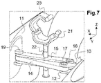
- the retaining flange is suitable for being placed in an open state ( figure 7 ) making it possible to provide a radial passage for depositing a portion of the bicycle frame tube in the receiving cradle 21 and in a closed state ( figure 8 ) making it possible to close said passage and to enclose the portion of tube 31 housed between the receiving cradle 21 and the retaining flange 23.
- the interior surfaces facing the retaining flange 23 and the receiving cradle 21 can be coated with rubber pads, so as to allow to generate a clamping pressure on the tube of the bicycle and thus to limit its movements.
- the retaining flange 23 can be connected to the reception cradle 21 by means of a lock 24 capable of being actuated by the ignition key 25 of the vehicle.
- This lock is for example arranged at the second ends respective receiving cradle 21 and retaining flange 23, opposite the respective first ends of receiving cradle 21 and retaining flange 23 articulated by the pivot connection.
Abstract
Porte-vélo pour véhicule automobile avec hayon arrière, comprenant une structure porteuse (10) mobile entre deux positions, une position repliée, où elle est peut-être logée dans un logement (4) dudit hayon, et une position déployée, où elle s'étend vers l'arrière du véhicule, dans un plan horizontal, ladite structure comportant un organe de support (20) comprenant un berceau de réception (21) d'une portion de cadre de vélo et un cache (11) pour venir fermer ledit logement en position repliée. Ladite structure porteuse est constituée par un ensemble plan de quatre barres (12,13,14,15) articulées entre elles deux à deux en parallélogramme déformable, deux premières barres comprenant une extrémité apte à être montée pivotante par rapport à une paroi avant dudit logement autour d'un axe commun (16) vertical apte à être lié à ladite paroi avant et deux secondes barres comprenant une extrémité libre reliée autour d'un axe commun (19) solidaire dudit cache.Bicycle carrier for a motor vehicle with a rear tailgate, comprising a supporting structure (10) movable between two positions, a folded position, where it may be housed in a housing (4) of said tailgate, and a deployed position, where it s 'extends towards the rear of the vehicle, in a horizontal plane, said structure comprising a support member (20) comprising a receiving cradle (21) of a portion of a bicycle frame and a cover (11) to close said housing in folded position. Said supporting structure is constituted by a planar assembly of four bars (12,13,14,15) articulated between them two by two in a deformable parallelogram, two first bars comprising one end capable of being mounted to pivot relative to a front wall of said housing around a common vertical axis (16) capable of being linked to said front wall and two second bars comprising a free end connected around a common axis (19) integral with said cover.
Description
L'invention concerne un porte-vélo escamotable pour véhicule automobile. La possibilité de transporter un ou plusieurs vélos sur leur véhicule automobile est un besoin de plus en plus répandu chez les usagers de véhicules automobiles.The invention relates to a retractable bicycle carrier for a motor vehicle. The possibility of transporting one or more bicycles on their motor vehicle is an increasingly widespread need among motor vehicle users.
Parmi les systèmes connus de porte-vélo, on connaît les porte-vélo sur hayon, qui comportent une armature dotée d'une fourche de réception pour un ou plusieurs vélos et apte à être fixée contre le hayon de coffre. Ce type de porte-vélo, qui présente l'avantage d'être amovible et montable rapidement sur le hayon de coffre, ne convient toutefois pas à tous les types de véhicule, notamment en raison de leur forme. De surcroît, le système de fixation contre le hayon de coffre peut endommager la peinture du véhicule, de même que les mouvements générés par une mauvaise adhérence du vélo sur le porte-vélo. Enfin, il existe un risque de désolidarisation du porte-vélo.Among the known bicycle carrier systems, there are known tailgate bicycle carriers, which comprise a frame provided with a receiving fork for one or more bicycles and capable of being fixed against the boot tailgate. This type of bicycle carrier, which has the advantage of being removable and quickly mountable on the boot lid, is however not suitable for all types of vehicle, in particular because of their shape. In addition, the mounting system against the boot lid can damage the paintwork of the vehicle, as can the movements generated by poor adhesion of the bike on the bike carrier. Finally, there is a risk of the bicycle carrier becoming detached.
On connaît aussi des portes-vélo sur moyen d'attelage, qui comportent un châssis supportant un ou plusieurs vélos et destiné à être monté rigidement sur une boule d'attelage solidaire du soubassement arrière du véhicule. Ce type de porte-vélos sur moyen d'attelage nécessite toutefois l'installation préalable en après-vente sur le véhicule d'une boule d'attelage.Also known are bicycle carriers on coupling means, which comprise a frame supporting one or more bicycles and intended to be mounted rigidly on a coupling ball integral with the rear base of the vehicle. However, this type of bicycle carrier on a coupling means requires the prior after-sales installation of a coupling ball on the vehicle.
On connaît aussi des portes-vélo escamotables pour véhicule automobile, intégrés au véhicule et destinés à se déployer à partir du véhicule depuis une configuration de rangement entre une position repliée et une position de transport (ou déployée). Ainsi, contrairement aux portes-vélo amovibles, qui doivent être retirés lorsqu'ils ne sont pas utilisés, ces portes-vélo sont montés à demeure sur le véhicule et disponibles à tout moment. Un tel porte-vélo est notamment connu par l'exemple qu'en donne le document de brevet
Cet agencement particulier de la structure porteuse permet certes de faciliter l'intégration du porte-vélo dans le véhicule, mais a pour inconvénient d'occuper une zone importante du hayon arrière du véhicule pour permettre d'y loger les deux bras porteurs. De surcroit, la mise en place des berceaux nécessitent une cinématique propre, au détriment de l'encombrement global.This particular arrangement of the supporting structure certainly makes it possible to facilitate the integration of the bicycle carrier into the vehicle, but has the drawback of occupying a large area of the rear hatch of the vehicle to allow the two supporting arms to be accommodated therein. In addition, the installation of the cradles requires its own kinematics, to the detriment of the overall size.
Un but de l'invention est de proposer un porte-vélo pour véhicule automobile, qui s'avère plus pratique, compact et ergonomique.An object of the invention is to provide a bicycle carrier for a motor vehicle, which proves to be more practical, compact and ergonomic.
A cet effet, l'invention concerne un porte-vélo pour véhicule automobile présentant un hayon arrière, ledit porte-vélo comprenant une structure porteuse adaptée pour être mobile entre au moins deux positions, respectivement une position repliée, dans laquelle elle est apte à être logée dans un logement prévu à cet effet dans ledit hayon, et une position déployée, dans laquelle elle est apte à s'étendre depuis ledit hayon, vers l'arrière du véhicule, dans un plan sensiblement horizontal, ladite structure porteuse étant pourvue d'au moins un organe de support comprenant un berceau de réception d'une portion de cadre de vélo et d'un cache adapté pour venir fermer ledit logement et masquer ladite structure porteuse lorsque celle-ci est dans sa position repliée, caractérisé en ce que ladite structure porteuse est constituée par un ensemble plan de quatre barres articulées entre elles deux à deux en parallélogramme déformable, deux premières barres comprenant une extrémité apte à être montée pivotante par rapport à une paroi avant dudit logement autour d'un axe commun sensiblement vertical apte à être lié à ladite paroi avant et deux secondes barres comprenant une extrémité libre reliée autour d'un axe commun solidaire dudit cache. Avantageusement, la position déployée correspond à la position extrême de déploiement maximal du parallélogramme déformable.To this end, the invention relates to a bicycle carrier for a motor vehicle having a rear hatch, said bicycle carrier comprising a supporting structure adapted to be movable between at least two positions, respectively a folded position, in which it is suitable for being. housed in a housing provided for this purpose in said tailgate, and an extended position, in which it is able to extend from said tailgate, towards the rear of the vehicle, in a substantially horizontal plane, said supporting structure being provided with at least one support member comprising a cradle for receiving a portion of a bicycle frame and a cover adapted to close said housing and hide said supporting structure when the latter is in its folded position, characterized in that said supporting structure consists of a flat assembly of four bars articulated together two by two in a deformable parallelogram, two first bars comprising one end capable of being mounted pivoting relative to a front wall of said housing about a common substantially vertical axis suitable for being linked to said front wall and two second bars comprising a free end connected around a common axis integral with said cover. Advantageously, the deployed position corresponds to the extreme position of maximum deployment of the deformable parallelogram.
Avantageusement, le porte-vélo peut comprendre un mécanisme de verrouillage de la structure porteuse dans sa position déployée.Advantageously, the bicycle carrier can include a mechanism for locking the supporting structure in its deployed position.
Avantageusement, ledit berceau de réception comporte une bride de maintien de la portion de cadre de vélo reçue dans ledit berceau de réception, ladite bride de maintien étant apte à être placée dans un état ouvert permettant de ménager un passage radial de dépose de la portion de cadre de vélo dans le berceau de réception et dans un état fermé permettant d'obturer ledit passage et dans lequel ladite bride de maintien est verrouillée sur ledit berceau de réception. Avantageusement, ladite bride de maintien est reliée au berceau de réception par l'intermédiaire d'un verrou apte à être actionné par la clé de contact du véhicule. Avantageusement, ledit organe de support comprend un mât-support faisant saillie d'une des deux secondes barres et à l'extrémité supérieure duquel est disposé le berceau de réception.Advantageously, said receiving cradle comprises a flange for retaining the portion of the bicycle frame received in said receiving cradle, said retaining flange being able to be placed in an open state making it possible to provide a radial passage for depositing the portion of bicycle frame in the receiving cradle and in a closed state allowing said passage to be closed and in which said retaining flange is locked on said receiving cradle. Advantageously, said retaining flange is connected to the receiving cradle by means of a lock capable of being actuated by the vehicle ignition key. Advantageously, said support member comprises a support mast projecting from one of the two second bars and at the upper end of which the reception cradle is placed.
Avantageusement, ledit mât-support est monté à coulissement vertical dans ladite une des secondes barres et à rotation par rapport à ladite une des secondes barres, des moyens d'indexation angulaire et de verrouillage étant prévus entre ledit mât-support et ladite une des secondes barres pour ne permettre le coulissement dudit mât-support que dans une position angulaire déterminée de celui-ci par rapport à ladite une des secondes barres et pour verrouiller ledit mât-support dans une position verticale déterminée. Avantageusement, lesdits moyens d'indexation angulaire et de verrouillage comprennent une pluralité de pions saillant transversalement dudit mât-support et alignés à intervalles réguliers le long dudit mât-support, lesdits pions étant aptes à être insérés dans une rainure verticale correspondante d'un logement de réception prévu dans ladite une des secondes barres, chaque pion étant apte à être clipsé dans ledit logement de réception par rotation dudit mât-support. D'autres caractéristiques et avantages de l'invention ressortiront clairement de la description qui en est faite ci-après, à titre indicatif et nullement limitatif, en référence aux dessins annexés sur lesquels :
- [
Fig. 1 ] représente schématiquement une vue arrière en perspective d'un véhicule automobile intégrant un porte-vélo selon l'invention dont la structure porteuse, faisant saillie du hayon arrière du véhicule, supporte un vélo disposé dans un plan vertical ; - [
Fig. 2 ] est une vue du côté du porte vélo selon l'invention en position déployée ; - [
Fig. 3 ] représente une vue arrière du porte-vélo selon l'invention en position repliée ; - [
Fig. 4 ] représente une vue arrière du porte-vélo selon l'invention en position déployée ; - [
Fig. 5 ] représente schématiquement une vue de détail de l'organe de support du porte-vélo de l'invention ; - [
Fig. 6 ] représente schématiquement une vue de détail du mât-support de l'organe de support du porte-vélo de l'invention ; - [
Fig. 7 ] représente schématiquement le berceau de réception de l'organe de support du porte vélo selon l'invention, dans une position ouverte ; - [
Fig. 8 ] représente schématiquement le berceau de réception de l'organe de support du porte vélo selon l'invention, dans une position fermée ; - [
Fig. 9 ] représente schématiquement une vue de détail du berceau de réception de l'organe de support du porte vélo selon l'invention.
- [
Fig. 1 ] schematically shows a rear perspective view of a motor vehicle incorporating a bicycle carrier according to the invention, the supporting structure of which, projecting from the rear hatch of the vehicle, supports a bicycle arranged in a vertical plane; - [
Fig. 2 ] is a side view of the bicycle carrier according to the invention in the deployed position; - [
Fig. 3 ] shows a rear view of the bicycle carrier according to the invention in the folded position; - [
Fig. 4 ] shows a rear view of the bicycle carrier according to the invention in the deployed position; - [
Fig. 5 ] schematically shows a detail view of the support member of the bicycle carrier of the invention; - [
Fig. 6 ] schematically shows a detail view of the support mast of the support member of the bicycle carrier of the invention; - [
Fig. 7 ] schematically shows the cradle for receiving the support member of the bicycle carrier according to the invention, in an open position; - [
Fig. 8 ] schematically shows the cradle for receiving the support member of the bicycle carrier according to the invention, in a closed position; - [
Fig. 9 ] schematically shows a detail view of the cradle for receiving the support member of the bicycle carrier according to the invention.
Pour les besoins de la description, on se réfèrera à un repère orthonormé direct XYZ, classiquement utilisé en conception automobile, dans lequel l'axe X désigne la direction longitudinale du véhicule, orienté vers l'arrière, l'axe Y désigne la direction transversale et est orienté vers la droite du véhicule, et l'axe Z désigne la direction verticale, et est orienté vers le haut. Par sensiblement horizontal ou vertical, on entend une direction/un plan formant un angle d'au plus ±10°, voire d'au plus ±5° avec une direction/un plan horizontal ou vertical. L'invention concerne donc un porte-vélo pour un véhicule automobile équipé d'un hayon. On peut voir sur la
La structure porteuse 10 du porte-vélo est donc conçue pour s'escamoter dans le logement 4 prévu à cet effet, lorsqu'il n'est pas utilisé, et pour se déplier depuis le hayon vers l'arrière du véhicule, dans un plan horizontal, lorsqu'il doit être utilisé. La structure porteuse 10 du porte-vélo est prévue pour être déployée manuellement.The supporting
En référence aux
Les
Ainsi, l'ensemble des quatre barres articulées12, 13, 14 et 15 forme une structure du type à parallélogramme déformable pouvant être déformée à volonté dans un plan horizontal entre la position repliée de la
Ainsi, grâce à cette liaison à parallélogramme déformable reliant la paroi avant 5 du logement 4 au cache 11, lorsque la structure porteuse 10 est déployée, l'extrémité libre du parallélogramme reliée au cache 11 subit une translation dans son plan, ce qui provoque son allongement et l'éloignement du cache 11 par rapport au logement 4, où l'autre extrémité du parallélogramme est fixée. La position déployée de la structure porteuse du porte-vélo, telle qu'illustrée à la
La position repliée de la structure porteuse 10 du porte-vélo, telle qu'illustrée à la
En référence à la
L'organe de support 20 est monté sur la seconde barre 15 de la structure porteuse 10 par l'intermédiaire d'un mât-support 22, faisant saillie verticalement de cette seconde barre et à l'extrémité supérieure duquel est disposé le berceau de réception 21. Le mât-support 22 peut coulisser verticalement par rapport à la seconde barre 15 sur laquelle il est monté, de façon à permettre d'adapter la hauteur du berceau de réception 21 par rapport à la structure porteuse 10, notamment en fonction du type de vélo destiné à être transporté.The
Pour ce faire, et comme on le voit mieux sur les vues de détail des
Par exemple, comme illustré sur la vue de détail de la
Le verrouillage d'une position verticale déterminée consiste à clipser le pion 220 correspondant à cette position verticale dans le logement de réception 151. Ce verrouillage peut s'effectuer par rotation du mât-support 22 autour de son axe, par exemple d'un quart de tour par rapport à la position de coulissement, permettant de loger le pion 220 qui a été inséré par translation dans le logement de réception, dans une rainure transversale à la rainure verticale ménagée à cet effet dans le logement de réception 151.The locking of a determined vertical position consists in clipping the
Dans la position de verrouillage du mât-support 22, l'axe du berceau de réception 21 est orienté transversalement par rapport à l'axe longitudinal du véhicule. Ainsi, les moyens d'indexation angulaire et de verrouillage prévus entre le mât-support 22 et la seconde barre 15 dans laquelle il est monté, permettent d'assurer une insertion du mât-support 22 dans le logement de réception 151 par indexation angulaire, puis une translation verticale du mât-support 22 à travers le logement de réception 151 jusqu'à atteindre la position verticale souhaitée et enfin un clipsage du pion correspondant à cette position verticale dans le logement de réception. Ceci représente solution très simple à mettre en œuvre. Le réglage de la position verticale du mât-support 22 est ainsi très aisé et très rapide.In the locking position of the
Comme illustré à la
Par ailleurs, le berceau de réception 21 de l'organe de support 20 peut comporter une bride de maintien 23 destinée à maintenir la portion de tube de cadre de vélo qui est reçue dans le berceau 21. Cette bride de maintien 23 est montée à pivotement sur le berceau de réception 21 suivant un axe parallèle à l'axe du berceau 21. Une liaison pivot selon cet axe est ainsi agencée au niveau de premières extrémités respectives du berceau de réception 21 et de la bride de maintien 23. Grâce à cette liaison, la bride de maintien est apte à être placée dans un état ouvert (
Claims (8)
Applications Claiming Priority (1)
| Application Number | Priority Date | Filing Date | Title |
|---|---|---|---|
| FR2003168A FR3108572B1 (en) | 2020-03-31 | 2020-03-31 | Retractable bike rack |
Publications (2)
| Publication Number | Publication Date |
|---|---|
| EP3888979A1 true EP3888979A1 (en) | 2021-10-06 |
| EP3888979B1 EP3888979B1 (en) | 2023-01-25 |
Family
ID=71452431
Family Applications (1)
| Application Number | Title | Priority Date | Filing Date |
|---|---|---|---|
| EP21162536.3A Active EP3888979B1 (en) | 2020-03-31 | 2021-03-15 | Retractable bike mount |
Country Status (2)
| Country | Link |
|---|---|
| EP (1) | EP3888979B1 (en) |
| FR (1) | FR3108572B1 (en) |
Citations (7)
| Publication number | Priority date | Publication date | Assignee | Title |
|---|---|---|---|---|
| JPH08175275A (en) * | 1994-12-27 | 1996-07-09 | Toyota Autom Loom Works Ltd | Carrier installation for automobile |
| EP1227004A1 (en) * | 2001-01-16 | 2002-07-31 | Wagon Automotive Snc | Cargo carrying device with at least two positions for automotive vehicle |
| FR2820382A1 (en) * | 2001-02-02 | 2002-08-09 | Peugeot Citroen Automobiles Sa | Cycle carrier for transport of cycle on rear of automobile comprises two separate units each with cycle support arm pivoted behind boot lid and gutters which receive and support cycle wheels |
| FR2855471A1 (en) * | 2003-06-02 | 2004-12-03 | Peugeot Citroen Automobiles Sa | Bike rack for motor vehicle, has structure with two tubes, each provided with two arms at end of fixing unit on receiving tube, where arms are confined between tubes in arrangement position with saddle and handlebar supports |
| EP1892153A2 (en) * | 2006-07-08 | 2008-02-27 | Magna Car Top Systems GmbH | Carrying device for a bicycle |
| EP2532554A1 (en) * | 2011-06-08 | 2012-12-12 | WESTFALIA - Automotive GmbH | Rear carrier for a passenger vehicle |
| US10343614B2 (en) | 2016-08-12 | 2019-07-09 | Ford Global Technologies, Llc | Vehicle with integrated carrying rack |
-
2020
- 2020-03-31 FR FR2003168A patent/FR3108572B1/en active Active
-
2021
- 2021-03-15 EP EP21162536.3A patent/EP3888979B1/en active Active
Patent Citations (7)
| Publication number | Priority date | Publication date | Assignee | Title |
|---|---|---|---|---|
| JPH08175275A (en) * | 1994-12-27 | 1996-07-09 | Toyota Autom Loom Works Ltd | Carrier installation for automobile |
| EP1227004A1 (en) * | 2001-01-16 | 2002-07-31 | Wagon Automotive Snc | Cargo carrying device with at least two positions for automotive vehicle |
| FR2820382A1 (en) * | 2001-02-02 | 2002-08-09 | Peugeot Citroen Automobiles Sa | Cycle carrier for transport of cycle on rear of automobile comprises two separate units each with cycle support arm pivoted behind boot lid and gutters which receive and support cycle wheels |
| FR2855471A1 (en) * | 2003-06-02 | 2004-12-03 | Peugeot Citroen Automobiles Sa | Bike rack for motor vehicle, has structure with two tubes, each provided with two arms at end of fixing unit on receiving tube, where arms are confined between tubes in arrangement position with saddle and handlebar supports |
| EP1892153A2 (en) * | 2006-07-08 | 2008-02-27 | Magna Car Top Systems GmbH | Carrying device for a bicycle |
| EP2532554A1 (en) * | 2011-06-08 | 2012-12-12 | WESTFALIA - Automotive GmbH | Rear carrier for a passenger vehicle |
| US10343614B2 (en) | 2016-08-12 | 2019-07-09 | Ford Global Technologies, Llc | Vehicle with integrated carrying rack |
Also Published As
| Publication number | Publication date |
|---|---|
| FR3108572B1 (en) | 2022-02-18 |
| FR3108572A1 (en) | 2021-10-01 |
| EP3888979B1 (en) | 2023-01-25 |
Similar Documents
| Publication | Publication Date | Title |
|---|---|---|
| EP1136321B1 (en) | Vehicle storage compartment, closed at its end by a bodywork element | |
| FR2845046A1 (en) | Stowable seat for motor vehicle has lateral sliding guides and pivot mounting for simultaneous lateral and pivoting movement | |
| FR2990167A1 (en) | SEAT, IN PARTICULAR FOR MOTOR VEHICLE | |
| FR2829082A1 (en) | Automobile rear transverse cycle carrier comprises two parallel arms, to which gutter shaped wheel support rails are fixed transversely, pivoting mounted at end about axis transverse to vehicle wing | |
| EP3381753B1 (en) | Tilting buckle | |
| EP3888979B1 (en) | Retractable bike mount | |
| FR2820382A1 (en) | Cycle carrier for transport of cycle on rear of automobile comprises two separate units each with cycle support arm pivoted behind boot lid and gutters which receive and support cycle wheels | |
| EP1227004B1 (en) | Cargo carrying device with at least two positions for automotive vehicle | |
| FR2990168A1 (en) | SEAT, IN PARTICULAR FOR MOTOR VEHICLE | |
| FR2974326A1 (en) | CONNECTION SYSTEM FOR FASTENING A CARRYING DEVICE | |
| EP3418124B1 (en) | Folding seat with storage device for headrest | |
| FR2893888A3 (en) | Luggage covering device for motor vehicle, has reel assemblies linked in end to end manner along longitudinal direction and having ends supported against each other in deployed position and arranged adjacent to each other in folded position | |
| FR3037010A1 (en) | RECOVERABLE SEAT PROVIDED WITH TRAINING MEANS ARRANGED BETWEEN THE SEAT AND THE BACKREST AND MOTOR VEHICLE COMPRISING SUCH A SEAT | |
| FR2923756A1 (en) | Lockable and unlockable pivoting assembly e.g. front pivoting assembly, for bonnet in convertible vehicle, has hook mounted on base, and wall carried by male element of casing such that locking device releasably locks casing and base | |
| EP3815969B1 (en) | Sewer-cleaning vehicle comprising an optimised storage tank | |
| FR2820381A1 (en) | Device for transport of cycle transversely in rear of automobile comprises two separate support arms pivoted behind boot lid | |
| EP3808597B1 (en) | Motor vehicle seat and motor vehicle | |
| FR2923762A1 (en) | Equipment i.e. armrest, for seat of e.g. commercial motor vehicle, has support arm with joint pivoting around axle that is placed laterally under base of seat such that bearing and support arms are placed under seat in retracted position | |
| WO2024028190A1 (en) | Transport and/or storage module | |
| WO2015164980A1 (en) | Modular trailer and attachment modules | |
| FR2909603A1 (en) | RETRACTABLE SEAT AND MOTOR VEHICLE COMPRISING SUCH A SEAT | |
| FR3119157A1 (en) | Multifunction luggage rack for cycle | |
| FR3140595A1 (en) | Vehicle opening including a bicycle support | |
| FR3103143A1 (en) | TRICBODY VEHICLE CONVERTISABLE INTO PICK-UP INCLUDING A SINGLE MULTIFUNCTIONAL TRUNK FLAP | |
| FR2993836A1 (en) | Bicycles support for supporting e.g. scooters at rear portion of car, has hoisting device for occupying kneeling position in which end of carrying beam is lowered to incline carrying beam around horizontal rotation axis |
Legal Events
| Date | Code | Title | Description |
|---|---|---|---|
| PUAI | Public reference made under article 153(3) epc to a published international application that has entered the european phase |
Free format text: ORIGINAL CODE: 0009012 |
|
| STAA | Information on the status of an ep patent application or granted ep patent |
Free format text: STATUS: THE APPLICATION HAS BEEN PUBLISHED |
|
| AK | Designated contracting states |
Kind code of ref document: A1 Designated state(s): AL AT BE BG CH CY CZ DE DK EE ES FI FR GB GR HR HU IE IS IT LI LT LU LV MC MK MT NL NO PL PT RO RS SE SI SK SM TR |
|
| RAP3 | Party data changed (applicant data changed or rights of an application transferred) |
Owner name: RENAULT S.A.S |
|
| STAA | Information on the status of an ep patent application or granted ep patent |
Free format text: STATUS: REQUEST FOR EXAMINATION WAS MADE |
|
| 17P | Request for examination filed |
Effective date: 20220325 |
|
| RBV | Designated contracting states (corrected) |
Designated state(s): AL AT BE BG CH CY CZ DE DK EE ES FI FR GB GR HR HU IE IS IT LI LT LU LV MC MK MT NL NO PL PT RO RS SE SI SK SM TR |
|
| RAP3 | Party data changed (applicant data changed or rights of an application transferred) |
Owner name: RENAULT S.A.S |
|
| GRAP | Despatch of communication of intention to grant a patent |
Free format text: ORIGINAL CODE: EPIDOSNIGR1 |
|
| STAA | Information on the status of an ep patent application or granted ep patent |
Free format text: STATUS: GRANT OF PATENT IS INTENDED |
|
| INTG | Intention to grant announced |
Effective date: 20220831 |
|
| GRAS | Grant fee paid |
Free format text: ORIGINAL CODE: EPIDOSNIGR3 |
|
| GRAA | (expected) grant |
Free format text: ORIGINAL CODE: 0009210 |
|
| STAA | Information on the status of an ep patent application or granted ep patent |
Free format text: STATUS: THE PATENT HAS BEEN GRANTED |
|
| AK | Designated contracting states |
Kind code of ref document: B1 Designated state(s): AL AT BE BG CH CY CZ DE DK EE ES FI FR GB GR HR HU IE IS IT LI LT LU LV MC MK MT NL NO PL PT RO RS SE SI SK SM TR |
|
| REG | Reference to a national code |
Ref country code: GB Ref legal event code: FG4D Free format text: NOT ENGLISH |
|
| REG | Reference to a national code |
Ref country code: CH Ref legal event code: EP |
|
| REG | Reference to a national code |
Ref country code: AT Ref legal event code: REF Ref document number: 1545702 Country of ref document: AT Kind code of ref document: T Effective date: 20230215 Ref country code: IE Ref legal event code: FG4D Free format text: LANGUAGE OF EP DOCUMENT: FRENCH |
|
| REG | Reference to a national code |
Ref country code: DE Ref legal event code: R096 Ref document number: 602021001292 Country of ref document: DE |
|
| PGFP | Annual fee paid to national office [announced via postgrant information from national office to epo] |
Ref country code: FR Payment date: 20230321 Year of fee payment: 3 |
|
| REG | Reference to a national code |
Ref country code: LT Ref legal event code: MG9D |
|
| PGFP | Annual fee paid to national office [announced via postgrant information from national office to epo] |
Ref country code: DE Payment date: 20230321 Year of fee payment: 3 |
|
| REG | Reference to a national code |
Ref country code: NL Ref legal event code: MP Effective date: 20230125 |
|
| REG | Reference to a national code |
Ref country code: AT Ref legal event code: MK05 Ref document number: 1545702 Country of ref document: AT Kind code of ref document: T Effective date: 20230125 |
|
| PG25 | Lapsed in a contracting state [announced via postgrant information from national office to epo] |
Ref country code: NL Free format text: LAPSE BECAUSE OF FAILURE TO SUBMIT A TRANSLATION OF THE DESCRIPTION OR TO PAY THE FEE WITHIN THE PRESCRIBED TIME-LIMIT Effective date: 20230125 |
|
| P01 | Opt-out of the competence of the unified patent court (upc) registered |
Effective date: 20230608 |
|
| PG25 | Lapsed in a contracting state [announced via postgrant information from national office to epo] |
Ref country code: RS Free format text: LAPSE BECAUSE OF FAILURE TO SUBMIT A TRANSLATION OF THE DESCRIPTION OR TO PAY THE FEE WITHIN THE PRESCRIBED TIME-LIMIT Effective date: 20230125 Ref country code: PT Free format text: LAPSE BECAUSE OF FAILURE TO SUBMIT A TRANSLATION OF THE DESCRIPTION OR TO PAY THE FEE WITHIN THE PRESCRIBED TIME-LIMIT Effective date: 20230525 Ref country code: NO Free format text: LAPSE BECAUSE OF FAILURE TO SUBMIT A TRANSLATION OF THE DESCRIPTION OR TO PAY THE FEE WITHIN THE PRESCRIBED TIME-LIMIT Effective date: 20230425 Ref country code: LV Free format text: LAPSE BECAUSE OF FAILURE TO SUBMIT A TRANSLATION OF THE DESCRIPTION OR TO PAY THE FEE WITHIN THE PRESCRIBED TIME-LIMIT Effective date: 20230125 Ref country code: LT Free format text: LAPSE BECAUSE OF FAILURE TO SUBMIT A TRANSLATION OF THE DESCRIPTION OR TO PAY THE FEE WITHIN THE PRESCRIBED TIME-LIMIT Effective date: 20230125 Ref country code: HR Free format text: LAPSE BECAUSE OF FAILURE TO SUBMIT A TRANSLATION OF THE DESCRIPTION OR TO PAY THE FEE WITHIN THE PRESCRIBED TIME-LIMIT Effective date: 20230125 Ref country code: ES Free format text: LAPSE BECAUSE OF FAILURE TO SUBMIT A TRANSLATION OF THE DESCRIPTION OR TO PAY THE FEE WITHIN THE PRESCRIBED TIME-LIMIT Effective date: 20230125 Ref country code: AT Free format text: LAPSE BECAUSE OF FAILURE TO SUBMIT A TRANSLATION OF THE DESCRIPTION OR TO PAY THE FEE WITHIN THE PRESCRIBED TIME-LIMIT Effective date: 20230125 |
|
| PG25 | Lapsed in a contracting state [announced via postgrant information from national office to epo] |
Ref country code: SE Free format text: LAPSE BECAUSE OF FAILURE TO SUBMIT A TRANSLATION OF THE DESCRIPTION OR TO PAY THE FEE WITHIN THE PRESCRIBED TIME-LIMIT Effective date: 20230125 Ref country code: PL Free format text: LAPSE BECAUSE OF FAILURE TO SUBMIT A TRANSLATION OF THE DESCRIPTION OR TO PAY THE FEE WITHIN THE PRESCRIBED TIME-LIMIT Effective date: 20230125 Ref country code: IS Free format text: LAPSE BECAUSE OF FAILURE TO SUBMIT A TRANSLATION OF THE DESCRIPTION OR TO PAY THE FEE WITHIN THE PRESCRIBED TIME-LIMIT Effective date: 20230525 Ref country code: GR Free format text: LAPSE BECAUSE OF FAILURE TO SUBMIT A TRANSLATION OF THE DESCRIPTION OR TO PAY THE FEE WITHIN THE PRESCRIBED TIME-LIMIT Effective date: 20230426 Ref country code: FI Free format text: LAPSE BECAUSE OF FAILURE TO SUBMIT A TRANSLATION OF THE DESCRIPTION OR TO PAY THE FEE WITHIN THE PRESCRIBED TIME-LIMIT Effective date: 20230125 |
|
| REG | Reference to a national code |
Ref country code: DE Ref legal event code: R097 Ref document number: 602021001292 Country of ref document: DE |
|
| PG25 | Lapsed in a contracting state [announced via postgrant information from national office to epo] |
Ref country code: SM Free format text: LAPSE BECAUSE OF FAILURE TO SUBMIT A TRANSLATION OF THE DESCRIPTION OR TO PAY THE FEE WITHIN THE PRESCRIBED TIME-LIMIT Effective date: 20230125 Ref country code: RO Free format text: LAPSE BECAUSE OF FAILURE TO SUBMIT A TRANSLATION OF THE DESCRIPTION OR TO PAY THE FEE WITHIN THE PRESCRIBED TIME-LIMIT Effective date: 20230125 Ref country code: MC Free format text: LAPSE BECAUSE OF FAILURE TO SUBMIT A TRANSLATION OF THE DESCRIPTION OR TO PAY THE FEE WITHIN THE PRESCRIBED TIME-LIMIT Effective date: 20230125 Ref country code: EE Free format text: LAPSE BECAUSE OF FAILURE TO SUBMIT A TRANSLATION OF THE DESCRIPTION OR TO PAY THE FEE WITHIN THE PRESCRIBED TIME-LIMIT Effective date: 20230125 Ref country code: DK Free format text: LAPSE BECAUSE OF FAILURE TO SUBMIT A TRANSLATION OF THE DESCRIPTION OR TO PAY THE FEE WITHIN THE PRESCRIBED TIME-LIMIT Effective date: 20230125 Ref country code: CZ Free format text: LAPSE BECAUSE OF FAILURE TO SUBMIT A TRANSLATION OF THE DESCRIPTION OR TO PAY THE FEE WITHIN THE PRESCRIBED TIME-LIMIT Effective date: 20230125 |
|
| PG25 | Lapsed in a contracting state [announced via postgrant information from national office to epo] |
Ref country code: SK Free format text: LAPSE BECAUSE OF FAILURE TO SUBMIT A TRANSLATION OF THE DESCRIPTION OR TO PAY THE FEE WITHIN THE PRESCRIBED TIME-LIMIT Effective date: 20230125 |
|
| REG | Reference to a national code |
Ref country code: BE Ref legal event code: MM Effective date: 20230331 |
|
| PLBE | No opposition filed within time limit |
Free format text: ORIGINAL CODE: 0009261 |
|
| STAA | Information on the status of an ep patent application or granted ep patent |
Free format text: STATUS: NO OPPOSITION FILED WITHIN TIME LIMIT |
|
| PG25 | Lapsed in a contracting state [announced via postgrant information from national office to epo] |
Ref country code: LU Free format text: LAPSE BECAUSE OF NON-PAYMENT OF DUE FEES Effective date: 20230315 |
|
| 26N | No opposition filed |
Effective date: 20231026 |
|
| REG | Reference to a national code |
Ref country code: IE Ref legal event code: MM4A |
|
| PG25 | Lapsed in a contracting state [announced via postgrant information from national office to epo] |
Ref country code: SI Free format text: LAPSE BECAUSE OF FAILURE TO SUBMIT A TRANSLATION OF THE DESCRIPTION OR TO PAY THE FEE WITHIN THE PRESCRIBED TIME-LIMIT Effective date: 20230125 Ref country code: IE Free format text: LAPSE BECAUSE OF NON-PAYMENT OF DUE FEES Effective date: 20230315 |
|
| PG25 | Lapsed in a contracting state [announced via postgrant information from national office to epo] |
Ref country code: BE Free format text: LAPSE BECAUSE OF NON-PAYMENT OF DUE FEES Effective date: 20230331 |