EP3882002B1 - Procédé de fabrication d'un bidon en matière plastique et moule de soufflage correspondant - Google Patents
Procédé de fabrication d'un bidon en matière plastique et moule de soufflage correspondant Download PDFInfo
- Publication number
- EP3882002B1 EP3882002B1 EP20163220.5A EP20163220A EP3882002B1 EP 3882002 B1 EP3882002 B1 EP 3882002B1 EP 20163220 A EP20163220 A EP 20163220A EP 3882002 B1 EP3882002 B1 EP 3882002B1
- Authority
- EP
- European Patent Office
- Prior art keywords
- blow mold
- hose
- blow
- gripping
- preform
- Prior art date
- Legal status (The legal status is an assumption and is not a legal conclusion. Google has not performed a legal analysis and makes no representation as to the accuracy of the status listed.)
- Active
Links
Images


Classifications
-
- B—PERFORMING OPERATIONS; TRANSPORTING
- B29—WORKING OF PLASTICS; WORKING OF SUBSTANCES IN A PLASTIC STATE IN GENERAL
- B29C—SHAPING OR JOINING OF PLASTICS; SHAPING OF MATERIAL IN A PLASTIC STATE, NOT OTHERWISE PROVIDED FOR; AFTER-TREATMENT OF THE SHAPED PRODUCTS, e.g. REPAIRING
- B29C49/00—Blow-moulding, i.e. blowing a preform or parison to a desired shape within a mould; Apparatus therefor
- B29C49/02—Combined blow-moulding and manufacture of the preform or the parison
- B29C49/04—Extrusion blow-moulding
- B29C49/04102—Extrusion blow-moulding extruding the material continuously
-
- B—PERFORMING OPERATIONS; TRANSPORTING
- B29—WORKING OF PLASTICS; WORKING OF SUBSTANCES IN A PLASTIC STATE IN GENERAL
- B29C—SHAPING OR JOINING OF PLASTICS; SHAPING OF MATERIAL IN A PLASTIC STATE, NOT OTHERWISE PROVIDED FOR; AFTER-TREATMENT OF THE SHAPED PRODUCTS, e.g. REPAIRING
- B29C49/00—Blow-moulding, i.e. blowing a preform or parison to a desired shape within a mould; Apparatus therefor
- B29C49/28—Blow-moulding apparatus
- B29C49/30—Blow-moulding apparatus having movable moulds or mould parts
-
- B—PERFORMING OPERATIONS; TRANSPORTING
- B29—WORKING OF PLASTICS; WORKING OF SUBSTANCES IN A PLASTIC STATE IN GENERAL
- B29C—SHAPING OR JOINING OF PLASTICS; SHAPING OF MATERIAL IN A PLASTIC STATE, NOT OTHERWISE PROVIDED FOR; AFTER-TREATMENT OF THE SHAPED PRODUCTS, e.g. REPAIRING
- B29C49/00—Blow-moulding, i.e. blowing a preform or parison to a desired shape within a mould; Apparatus therefor
- B29C49/42—Component parts, details or accessories; Auxiliary operations
- B29C49/4205—Handling means, e.g. transfer, loading or discharging means
- B29C49/42073—Grippers
-
- B—PERFORMING OPERATIONS; TRANSPORTING
- B29—WORKING OF PLASTICS; WORKING OF SUBSTANCES IN A PLASTIC STATE IN GENERAL
- B29C—SHAPING OR JOINING OF PLASTICS; SHAPING OF MATERIAL IN A PLASTIC STATE, NOT OTHERWISE PROVIDED FOR; AFTER-TREATMENT OF THE SHAPED PRODUCTS, e.g. REPAIRING
- B29C49/00—Blow-moulding, i.e. blowing a preform or parison to a desired shape within a mould; Apparatus therefor
- B29C49/42—Component parts, details or accessories; Auxiliary operations
- B29C49/4242—Means for deforming the parison prior to the blowing operation
-
- B—PERFORMING OPERATIONS; TRANSPORTING
- B29—WORKING OF PLASTICS; WORKING OF SUBSTANCES IN A PLASTIC STATE IN GENERAL
- B29C—SHAPING OR JOINING OF PLASTICS; SHAPING OF MATERIAL IN A PLASTIC STATE, NOT OTHERWISE PROVIDED FOR; AFTER-TREATMENT OF THE SHAPED PRODUCTS, e.g. REPAIRING
- B29C49/00—Blow-moulding, i.e. blowing a preform or parison to a desired shape within a mould; Apparatus therefor
- B29C49/42—Component parts, details or accessories; Auxiliary operations
- B29C49/4252—Auxiliary operations prior to the blow-moulding operation not otherwise provided for
-
- B—PERFORMING OPERATIONS; TRANSPORTING
- B29—WORKING OF PLASTICS; WORKING OF SUBSTANCES IN A PLASTIC STATE IN GENERAL
- B29C—SHAPING OR JOINING OF PLASTICS; SHAPING OF MATERIAL IN A PLASTIC STATE, NOT OTHERWISE PROVIDED FOR; AFTER-TREATMENT OF THE SHAPED PRODUCTS, e.g. REPAIRING
- B29C49/00—Blow-moulding, i.e. blowing a preform or parison to a desired shape within a mould; Apparatus therefor
- B29C49/42—Component parts, details or accessories; Auxiliary operations
- B29C49/58—Blowing means
-
- B—PERFORMING OPERATIONS; TRANSPORTING
- B65—CONVEYING; PACKING; STORING; HANDLING THIN OR FILAMENTARY MATERIAL
- B65D—CONTAINERS FOR STORAGE OR TRANSPORT OF ARTICLES OR MATERIALS, e.g. BAGS, BARRELS, BOTTLES, BOXES, CANS, CARTONS, CRATES, DRUMS, JARS, TANKS, HOPPERS, FORWARDING CONTAINERS; ACCESSORIES, CLOSURES, OR FITTINGS THEREFOR; PACKAGING ELEMENTS; PACKAGES
- B65D1/00—Rigid or semi-rigid containers having bodies formed in one piece, e.g. by casting metallic material, by moulding plastics, by blowing vitreous material, by throwing ceramic material, by moulding pulped fibrous material or by deep-drawing operations performed on sheet material
- B65D1/12—Cans, casks, barrels, or drums
- B65D1/20—Cans, casks, barrels, or drums characterised by location or arrangement of filling or discharge apertures
-
- B—PERFORMING OPERATIONS; TRANSPORTING
- B65—CONVEYING; PACKING; STORING; HANDLING THIN OR FILAMENTARY MATERIAL
- B65D—CONTAINERS FOR STORAGE OR TRANSPORT OF ARTICLES OR MATERIALS, e.g. BAGS, BARRELS, BOTTLES, BOXES, CANS, CARTONS, CRATES, DRUMS, JARS, TANKS, HOPPERS, FORWARDING CONTAINERS; ACCESSORIES, CLOSURES, OR FITTINGS THEREFOR; PACKAGING ELEMENTS; PACKAGES
- B65D51/00—Closures not otherwise provided for
- B65D51/16—Closures not otherwise provided for with means for venting air or gas
- B65D51/1605—Closures not otherwise provided for with means for venting air or gas whereby the interior of the container is maintained in permanent gaseous communication with the exterior
- B65D51/1611—Closures not otherwise provided for with means for venting air or gas whereby the interior of the container is maintained in permanent gaseous communication with the exterior by means of an orifice, capillary or labyrinth passage
-
- B—PERFORMING OPERATIONS; TRANSPORTING
- B29—WORKING OF PLASTICS; WORKING OF SUBSTANCES IN A PLASTIC STATE IN GENERAL
- B29C—SHAPING OR JOINING OF PLASTICS; SHAPING OF MATERIAL IN A PLASTIC STATE, NOT OTHERWISE PROVIDED FOR; AFTER-TREATMENT OF THE SHAPED PRODUCTS, e.g. REPAIRING
- B29C49/00—Blow-moulding, i.e. blowing a preform or parison to a desired shape within a mould; Apparatus therefor
- B29C49/02—Combined blow-moulding and manufacture of the preform or the parison
- B29C2049/023—Combined blow-moulding and manufacture of the preform or the parison using inherent heat of the preform, i.e. 1 step blow moulding
-
- B—PERFORMING OPERATIONS; TRANSPORTING
- B29—WORKING OF PLASTICS; WORKING OF SUBSTANCES IN A PLASTIC STATE IN GENERAL
- B29C—SHAPING OR JOINING OF PLASTICS; SHAPING OF MATERIAL IN A PLASTIC STATE, NOT OTHERWISE PROVIDED FOR; AFTER-TREATMENT OF THE SHAPED PRODUCTS, e.g. REPAIRING
- B29C49/00—Blow-moulding, i.e. blowing a preform or parison to a desired shape within a mould; Apparatus therefor
- B29C49/42—Component parts, details or accessories; Auxiliary operations
- B29C49/58—Blowing means
- B29C2049/5841—Plural independent blowing paths
-
- B—PERFORMING OPERATIONS; TRANSPORTING
- B29—WORKING OF PLASTICS; WORKING OF SUBSTANCES IN A PLASTIC STATE IN GENERAL
- B29C—SHAPING OR JOINING OF PLASTICS; SHAPING OF MATERIAL IN A PLASTIC STATE, NOT OTHERWISE PROVIDED FOR; AFTER-TREATMENT OF THE SHAPED PRODUCTS, e.g. REPAIRING
- B29C49/00—Blow-moulding, i.e. blowing a preform or parison to a desired shape within a mould; Apparatus therefor
- B29C49/42—Component parts, details or accessories; Auxiliary operations
- B29C49/58—Blowing means
- B29C2049/5844—Compacting means, e.g. to compact the neck portion of the blown article with the blowing means
-
- B—PERFORMING OPERATIONS; TRANSPORTING
- B29—WORKING OF PLASTICS; WORKING OF SUBSTANCES IN A PLASTIC STATE IN GENERAL
- B29C—SHAPING OR JOINING OF PLASTICS; SHAPING OF MATERIAL IN A PLASTIC STATE, NOT OTHERWISE PROVIDED FOR; AFTER-TREATMENT OF THE SHAPED PRODUCTS, e.g. REPAIRING
- B29C2793/00—Shaping techniques involving a cutting or machining operation
- B29C2793/0027—Cutting off
-
- B—PERFORMING OPERATIONS; TRANSPORTING
- B29—WORKING OF PLASTICS; WORKING OF SUBSTANCES IN A PLASTIC STATE IN GENERAL
- B29C—SHAPING OR JOINING OF PLASTICS; SHAPING OF MATERIAL IN A PLASTIC STATE, NOT OTHERWISE PROVIDED FOR; AFTER-TREATMENT OF THE SHAPED PRODUCTS, e.g. REPAIRING
- B29C49/00—Blow-moulding, i.e. blowing a preform or parison to a desired shape within a mould; Apparatus therefor
- B29C49/02—Combined blow-moulding and manufacture of the preform or the parison
- B29C49/04—Extrusion blow-moulding
- B29C49/04118—Means for supporting the extruded parison
-
- B—PERFORMING OPERATIONS; TRANSPORTING
- B29—WORKING OF PLASTICS; WORKING OF SUBSTANCES IN A PLASTIC STATE IN GENERAL
- B29K—INDEXING SCHEME ASSOCIATED WITH SUBCLASSES B29B, B29C OR B29D, RELATING TO MOULDING MATERIALS OR TO MATERIALS FOR MOULDS, REINFORCEMENTS, FILLERS OR PREFORMED PARTS, e.g. INSERTS
- B29K2105/00—Condition, form or state of moulded material or of the material to be shaped
- B29K2105/25—Solid
- B29K2105/253—Preform
- B29K2105/258—Tubular
-
- B—PERFORMING OPERATIONS; TRANSPORTING
- B29—WORKING OF PLASTICS; WORKING OF SUBSTANCES IN A PLASTIC STATE IN GENERAL
- B29L—INDEXING SCHEME ASSOCIATED WITH SUBCLASS B29C, RELATING TO PARTICULAR ARTICLES
- B29L2031/00—Other particular articles
- B29L2031/712—Containers; Packaging elements or accessories, Packages
- B29L2031/7158—Bottles
Definitions
- the invention relates to a method for producing a plastic canister.
- the invention also relates to a blow mold for producing a plastic canister.
- the registration shows a previously known canister, for example EP 0 677 445 A1 .
- the canister disclosed there is a plastic canister with a ventilation channel formed on the top floor and extending vertically within the pouring opening to enable gurgling-free emptying.
- the canister disclosed there is produced in the extrusion blow molding process using an accumulator blow head.
- the extruded tube which is open at the bottom, moves between the open blow mold halves over the blow pin positioned below.
- the blow pin can then be moved horizontally within the plasticized plastic tube into the desired, mostly asymmetrical position in which the pouring opening of the canister is to be formed.
- the blow mold then closes and the plasticized plastic tube is inflated inside the blow mold.
- the disadvantage of this method is that the extrusion of the hose cannot continue continuously during the inflation process, since the blow mold including the blow pin is located directly under the outlet of the accumulator blow head during the entire production period of the canister and thus hinders the further ejection of a new hose .
- the duration of the hose ejection is always added to the inflation time of the canister, which extends the total production time of the canister.
- EP 3 178 629 A1 shows a blow molding process for making a hollow article. The positioning of an extruded tube in an open blow mold is shown. The hose is gripped with a hose gripper to clamp the hose and keep it open on its upper side. The gripped hose is cut off above the hose gripper and moved horizontally. A blow pin arrangement is inserted into the entry opening from above and the preform is inflated in the blow mold to form a hollow object.
- this document shows a blow mold according to the preamble of claim 10.
- the aforementioned canister with a vertically extending inside the pouring opening A ventilation channel and a canister with an internal thread in the pouring opening cannot be produced using the faster blowing process of continuous extrusion.
- the extruded tube is continuously ejected. Is the required When the tube length is reached, the open blow mold halves waiting in the adjacent position move in front of and behind the tube, close and clamp it in order to return to the adjacent position with the clamped tube after it has been cut on the extruder drive. A corresponding blow pin then moves vertically into the opening made in the blow mold from above, dividing the jammed tube, thus forming the canister pouring opening and blowing the tube open.
- the vertically penetrating blow pin pushes excess plasticized material down into the interior of the produced canister, which in the case of a canister pouring opening with a ventilation channel formed inside it causes the same to close or, in the case of an opening with an internal thread, damages the threads.
- the blow mold can be opened and the canister removed in the usual way.
- the tube continues to extrude at the extrusion head, so that after the canister has been removed, the opened blow mold is moved horizontally under the tube head again in order to grasp the next preform with the tube gripper.
- blow mold or “open” blow mold half described here refer to a state of the blow mold in which the blow mold halves are at least not completely closed. In particular, the two blow mold halves are moved at least so far apart that the preform can hang between them with a sufficiently large insertion opening.
- the canister produced with the method according to the invention has in particular the following features.
- the canister preferably comprises a nozzle for pouring in and pouring out.
- a ventilation duct preferably protrudes into this connecting piece.
- the ventilation channel in turn preferably comprises a horizontal section and a vertical section. The vertical section of the ventilation channel preferably extends into the connecting piece and preferably ends below the upper end of the connecting piece.
- the ventilation duct leads over the horizontal section to a rear area of the interior space.
- the purpose of the ventilation duct is in EP 0 677 445 A1 described in detail.
- the blow pin arrangement used in the context of the method preferably comprises a main blow pin and a secondary blow pin.
- a pinch edge gap is preferably provided between the main blowing mandrel and the secondary blowing mandrel.
- the two blow mold halves have a pinch edge. The two opposite pinch edges of the two blow mold halves When the blow mold is closed, protrude into this squeeze edge gap between the main blowing mandrel and secondary blowing mandrel, so that an inner duct wall of the ventilation duct is created in the area of the nozzle.
- the hose gripper includes gripping elements.
- the parts that can be moved relative to the blow mold halves in order to clamp the hose between the gripping elements are referred to as gripping elements.
- the respective gripping element is movably guided on its blow mold half, so that the gripping elements can be moved towards one another in the mold closing direction of the blow mold.
- Gripping areas are defined on the gripping elements that actually make contact with the hose.
- a gripping area consists of two opposing, mutually complementary surfaces of two gripping elements.
- the hose gripper comprises at least two gripping areas that are spaced apart from one another. The hose is clamped at each gripping area. Because the two gripping areas are spaced apart from one another, the described insertion opening remains between the two gripping areas.
- the gripping elements are spring-loaded in the mold closing direction by means of springs. In particular, at least one spring is provided per gripping element, which in the tensioned state presses the gripping element in the direction of the hose, so that the hose can be clamped.
- At least one holding device is provided in particular on each blow mold half.
- This holding device can hold the corresponding gripping element or can block the relaxation of the spring in some other way so that the hose gripper does not close.
- the holding devices are preferably designed hydraulically or pneumatically, for example as hydraulic cylinders or pneumatic cylinders.
- the springs can be spiral springs or other energy stores, for example hydraulic or pneumatic energy stores.
- the springs are tensioned when the blow mold halves are closed. This is possible in a simple manner, since the gripping elements are closed anyway before the blow mold halves are closed and thereby clamp the preform. If the blow mold halves are now also moved towards one another, the springs automatically open up again as a result. When you then open the Blow mold halves, the springs are held in the tensioned state, in particular by the holding devices listed above.
- the individual gripping elements are each in two parts.
- the two parts of the respective gripping element can be moved in the horizontal direction perpendicular to the mold closing direction. This makes it possible for the two gripping areas to be moved towards one another after being clamped in order to change the shape of the entry opening.
- an essentially oval entry opening is formed between the two gripping areas.
- compressed air for pre-blowing is blown into the preform before the blow mold halves are closed, that is to say for example during the horizontal movement of the blow mold to the blow position or in the blow position.
- This pre-blowing can also be referred to as "pre-stretching”.
- the preform is inflated beyond the internal dimension of the blow mold during pre-blowing. Until the blow mold is closed, the preform orients itself back a little so that it fits into the mold cavity.
- the blow pin arrangement can be moved in the horizontal direction after it has been moved into the entry opening and before the blow mold halves are closed. This enables, for example, a very far outside connection of the canister.
- the auxiliary mandrel of the blow mandrel arrangement has at least one obliquely arranged compressed air outlet on its underside.
- the compressed air outlet When the canister is inflated, the compressed air can not only be blown vertically downwards, but also laterally onto the material (plastic). This makes it possible to blow away material to support the shaping process that was forced into the ventilation channel when the two halves of the blow mold were closed.
- the invention further comprises a blow mold for producing a canister.
- a blow mold for producing a canister.
- the blow mold will used in particular to carry out the procedure. It goes without saying that not only the blow mold, but also other elements, in particular the blow head for extruding the tube, can be used to carry out the method.
- the blow mold according to the invention comprises two blow mold halves which, with their mold cavity, give shape to the canister. The two blow mold halves can have slides in order to take into account the geometry of the desired canister.
- the already described hose gripper with its two gripping elements is located on the blow mold halves.
- the gripping elements can be moved parallel to the mold closing direction and relative to the respective blow mold half, so that the tube arranged between the opened blow mold halves can be clamped by the gripping elements without the blow mold halves having to be completely closed.
- the hose gripper has two gripping areas.
- the respective gripping area is formed by two opposing surfaces of two gripping elements that can be moved towards one another. As described, these two gripping areas are spaced apart from one another, so that there is an entry opening in the hose when it is clamped by the hose gripper.
- the hose gripper preferably comprises at least one spring per gripping element. As already described, this spring is designed as any energy storage device, for example as a spiral spring or in some other way.
- the springs act on the gripping elements towards one another, so that the gripping elements close by means of the spring force in order to clamp the hose.
- the hose gripper comprises holding devices which are designed to hold the gripping elements in the open, spring-loaded position.
- These holding devices are, for example, hydraulic or pneumatic cylinders.
- the holding devices are double-acting cylinders, so that, by applying pressure to the cylinders, it is possible on the one hand to hold open against the spring force and, on the other hand, to close the gripping elements supporting the spring force.
- FIG. 1 shows an arrangement 100 which can be used in carrying out the method. The representation is purely schematic.
- the arrangement 100 comprises a blow head 101 with which a hose 102 made of plastic is continuously extruded.
- the hose 102 hangs down from the blow head 101 along the vertical 110.
- the schematic representation in Fig. 1 that the arrangement 100 comprises a blow mold 1.
- This blow mold 1 in turn has two opposite blow mold halves 2.
- a hose gripper 3 is located on these blow mold halves 2.
- a separating device 103 for separating and simultaneously closing the tube 102 is located above the tube gripper 3.
- the tube 102 is continuously extruded.
- the blow mold 1 is regularly positioned on the tube 102 with the blow mold halves 2 open.
- the blow mold halves 2 are then not closed, but rather the tube 102 is merely clamped with the tube gripper 3.
- the tube 102 is then separated over the tube gripper 3 with the separating device 103, so that the preform 106 remains, which hangs between the two blow mold halves 2.
- the blow mold 1 together with the preform 106 hanging therein is displaced along the horizontal 111 into a blow position 105. As a result, the blow mold 1 is no longer located under the tube 102, which continues to extrude continuously.
- the in Fig. 1 The blow pin arrangement 30, shown purely schematically, is moved into the preform 106 along the vertical 110.
- the blow mold halves 2 are then closed and the preform 106 is inflated to form the canister 50, as is shown, for example, in FIG Figures 5 and 6 is shown.
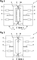
- Fig. 2 shows a plan view of the opened blow mold 1.
- Fig. 3 shows a plan view of the closed blow mold 1.
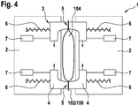
- Fig. 4 shows a plan view of an alternative embodiment of the blow mold 1, shown in the open state.
- the blow mold 1 comprises two blow mold halves 2 and a tube gripper 3.
- the tube gripper 3 in turn comprises two gripping elements 4.
- a gripping element 4 is arranged on the upper side of each blow mold half 2.
- Each gripping element 4 is movable along the horizontal 111 parallel to the mold closing direction 11 relative to the blow mold half 2.
- the hose gripper 3 is closed in each case.
- the two opposite gripping elements 4 are moved towards one another.
- the tube 102 or the preform 106 is clamped in at two spaced gripping areas 5. Because the two gripping areas 5 are spaced apart from one another, an entry opening 104 remains in the tube 102 or preform 106 between the two gripping areas 5 Mold closing direction 11 are closed.
- the Figs. 2 to 4 show, purely schematically, that the gripping elements 4 are acted upon by springs 6 in the direction of their closed position. These springs 6 press the gripping elements 4 towards one another.
- holding devices 7, for example designed as pneumatic or Hydraulic cylinder the gripping elements 4 can be held in their open position against the spring force.
- Fig. 3 shows a plan view of the blow mold 1 in the closed position.
- the blow mold halves 2 are completely closed.
- the insertion opening 104 has closed.
- the blow pin arrangement 30 protrudes into the preform 106 from above.
- Fig. 4 shows a variant in which the gripping elements 4 on the respective blow mold halves 2 are designed in two parts.
- the gripping elements 4 can be moved towards one another in such a way that the gripping areas 5 can be moved towards one another.
- the oval shape of the entry opening 104 can be changed to a more rounded shape.
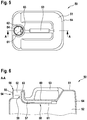
- Fig. 5 shows a plan view of the canister 50, which is produced with the arrangement 100 or the blow mold 1.
- Fig. 6 shows the in Fig. 5 marked section AA.
- the canister 50 comprises an upper floor 51 and an opposite lower floor (not shown).
- the upper floor 51 and the lower floor are connected via a jacket surface 64 of the canister 50.
- the upper floor 51, lower floor and jacket surface 64 thus form an interior space 52 of the canister 50 for receiving a liquid.
- a handle 53 is formed on the top floor 51. In front of the handle 53 there is a nozzle 54, designed for pouring the liquid into and out of the interior 52 or from the interior 52.
- the connecting piece 54 ends with an upper termination 56.
- a ventilation channel 57 is located on the inside of the top floor 51.
- the ventilation channel 57 is divided into a horizontal section 58 and a vertical section 59.
- the ventilation channel 57 is formed by an outer channel wall 60 and an inner channel wall 61.
- the inner channel wall 61 is formed in particular by squeezing off the preform 106. For this purpose, pinch edges 8 (s. Fig. 7 ) used on the blow mold halves 2.
- the outer channel wall 60 is in particular an outer wall of the canister 50.
- the ventilation channel 57 protrudes with its vertical section 59 into the connection piece 54. From the connection piece 54, the vertical section 59 extends downward and merges into the horizontal section 58. The horizontal section 58 extends into the rear region of the Canister 50 and opens into the interior 52. The horizontal section 58 does not have to run exactly horizontally, but can also run inclined.
- the inner channel wall 61 divides the interior of the connector 54 into a main opening 62, through which the liquid runs during pouring and pouring, and into a ventilation opening 63. that the ventilation opening 63 is significantly smaller in cross section than the main opening 62.
- the cross-sectional area of the ventilation opening 63 is at most 25%, preferably at most 20%, of the cross-sectional area of the main opening 62.
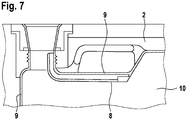
- Fig. 7 shows a region of one of the two blow mold halves 2. It can be seen that the corresponding part of the mold cavity 10 is formed in the blow mold half 2. Around the mold cavity 10, cutting edges 9 run which, together with the cutting edges of the other blow mold half 2, close and separate the preform 106.
- blow mold halves 2 each have a squeezing edge 8 which squeezes the preform 106 to form the inner channel wall 61.
- These pinch edges 8 also extend in the area of the connector 54, corresponding to the vertical section 59 of the ventilation channel 57.
- Fig. 8 shows how the mandrel assembly 30 is inserted into the canister 50.
- Fig. 9 the in Fig. 8 marked section BB.
- the blow pin arrangement 30 comprises a main blow pin 31 and a secondary blow pin 32.
- the main blow pin 31 is located in the area of the nozzle 54 and is thereby shaping the inside of the main opening 62.
- the secondary blow pin 32 is located at the same time also when the blow mold halves 2 are closed and when the canister 50 is inflated in the area of the connector 54 and is thereby shaping for the inner surface of the ventilation opening 63 or the vertical section 59 of the ventilation channel 57.
- the main blowing mandrel 31 and the secondary blowing mandrel 32 are spaced from one another by a pinch edge gap 36. Since the blow pin arrangement 30 is already in place when the blow mold halves 2 are closed, the two pinch edges 8 squeeze the material into the pinch edge gap 36. The pinch edges 8 of the blow mold halves 2 also protrude into this pinch edge gap 36 no material is displaced into the ventilation channel 57 to be created, in particular the vertical section 59.
- the two blow pins 31, 32 each have a central blow channel 33 for blowing compressed air into the interior 52.
- a return flow channel 34 is arranged around the blow channel 33.
- the secondary blowing mandrel 32 can have an inclined compressed air outlet 35 or several of these inclined compressed air outlets 35 on its underside. Air is blown out at an angle to the vertical 110 via this compressed air outlet 35. As a result, any material forced into the ventilation channel 57 that is created can be blown away, so that the desired cross-section of the ventilation channel 57 is created.
- At least one of the gripping elements 4 has a compressed air nozzle which enables the preform 106 to be pre-blown before the blow mold halves 2 are closed.
Landscapes
- Engineering & Computer Science (AREA)
- Mechanical Engineering (AREA)
- Manufacturing & Machinery (AREA)
- Ceramic Engineering (AREA)
- Blow-Moulding Or Thermoforming Of Plastics Or The Like (AREA)
- Moulds For Moulding Plastics Or The Like (AREA)
Claims (12)
- Procédé de fabrication d'un bidon (50) en matière plastique, comprenant les étapes suivantes :- l'extrusion continue d'un tuyau flexible (102),- le positionnement d'un moule de soufflage (1) ouvert autour du tuyau flexible (102) de sorte que le tuyau flexible (102) se trouve entre les deux moitiés de moule de soufflage (2),- la fermeture d'une pince de tuyau flexible (3) agencée au niveau du moule de soufflage (1) pour le serrage du tuyau flexible (102) et le maintien ouvert simultané du tuyau flexible (102) au niveau de son côté supérieur pour la formation d'une ouverture d'entrée (104),- la séparation du tuyau flexible (102) au-dessus de la pince de tuyau flexible (3) pour la formation de l'ébauche (106),- le déplacement horizontal du moule de soufflage (1) avec l'ébauche (106) s'accrochant dans celui-ci, maintenue par la pince de tuyau flexible (3) dans une position de soufflage (105),- l'entrée d'un agencement d'épine de soufflage (30) de dessus dans l'ouverture d'entrée (104) de l'ébauche (106),- la fermeture des moitiés de moule de soufflage (2),- le soufflage de l'ébauche (106) dans le moule de soufflage (1) pour former un bidon (50),- dans lequel la pince de tuyau flexible (3) serre le tuyau flexible (102) avec deux zones de préhension (5) au niveau de deux points espacés l'un de l'autre de sorte que l'ouverture d'entrée (104) présente une section transversale ovale.
- Procédé (59) selon la revendication 1,- dans lequel le bidon (50) présente une tubulure (54) pour le versement et le déversement,- dans lequel une section verticale (59) d'un canal de ventilation (57) du bidon (50) pénètre dans la tubulure (54),- dans lequel l'agencement d'épine de soufflage (30) réalise le formage lors de la fermeture des moitiés de moule de soufflage (2) avec une épine de soufflage principale (31) pour la tubulure (54) et avec une épine de soufflage accessoire (32) pour la section verticale (59) du canal de ventilation (57).
- Procédé selon l'une quelconque des revendications précédentes, dans lequel la pince de tuyau flexible (3) comporte sur chaque moitié de moule de soufflage (2) au moins un élément de préhension (4), dans lequel le tuyau flexible (102) peut être serré entre les éléments de préhension (4).
- Procédé selon la revendication 3, dans lequel les éléments de préhension (4) sont sollicités par ressort dans le sens de fermeture au moyen de ressorts (6), dans lequel pour le serrage du tuyau flexible (102) les ressorts (6) sont détendus, dans lequel lors de la fermeture des moitiés de moule de soufflage (2) les ressorts (6) sont tendus, et dans lequel lors de l'ouverture des moitiés de moule de soufflage (2) les ressorts (6) sont maintenus dans l'état tendu.
- Procédé selon l'une quelconque des revendications précédentes, dans lequel les deux zones de préhension (5) sont déplacées après le serrage pour la modification de forme de l'ouverture d'entrée (104) l'une vers l'autre.
- Procédé selon l'une quelconque des revendications précédentes, dans lequel de l'air comprimé est soufflé dans l'ébauche (106) avant la fermeture des moitiés de moule de soufflage (2) pour le présoufflage de l'ébauche (106) ; de préférence par le biais d'au moins une buse d'air comprimé au niveau d'au moins un des éléments de préhension (4).
- Procédé selon la revendication 6, dans lequel l'ébauche (106) est soufflée lors du présoufflage au-delà de la mesure de moule intérieure du moule de soufflage (1).
- Procédé selon l'une quelconque des revendications précédentes, dans lequel l'agencement d'épine de soufflage (30) est déplacé horizontalement après l'entrée dans l'ouverture d'entrée (104) et avant la fermeture des moitiés de moule de soufflage (2).
- Procédé selon l'une quelconque des revendications 2 à 8, dans lequel l'épine de soufflage accessoire (32) présente au niveau de son côté inférieur au moins une sortie d'air comprimé (35) agencée en biais et du matériau est évacué par soufflage lors du soufflage du bidon (50) par le biais de cette sortie d'air comprimé (35) pour le démoulage en appui du canal de ventilation (57).
- Moule de soufflage (1) pour la fabrication d'un bidon (50) en matière plastique, en particulier pour la réalisation du procédé selon l'une quelconque des revendications précédentes, comprenant :- deux moitiés de moule de soufflage (2), réalisant le formage pour le bidon (50),- et une pince de tuyau flexible (3) avec au moins un élément de préhension (4) sur le côté supérieur de l'une moitié de moule de soufflage (2) et au moins un élément de préhension (4) opposé sur le côté supérieur de l'autre moitié de moule de soufflage (2),- dans lequel les éléments de préhension (4) sont déplaçables par rapport à la moitié de moule de soufflage (2) de sorte qu'un tuyau flexible (102) agencé entre les moitiés de moule de soufflage (2) ouvertes puisse être serré par les éléments de préhension (4) sans fermer les moitiés de moule de soufflage (2),- caractérisé en ce que la pince de tuyau flexible (3) présente deux zones de préhension (5) respectivement pour le serrage du tuyau flexible (102), dans lequel les deux zones de préhension (5) sont espacées l'une de l'autre pour la formation d'une ouverture d'entrée (104) avec une section transversale ovale dans le tuyau flexible (102).
- Moule de soufflage selon la revendication 10, comprenant par élément de préhension (4) au moins un ressort (6) qui sollicite l'élément de préhension (4) dans le sens de fermeture, et un dispositif de maintien (7) réalisé pour le maintien et la libération de l'élément de préhension (4) sollicité par ressort.
- Moule de soufflage selon l'une quelconque des revendications 10 ou 11, dans lequel les deux zones de préhension (5) sont déplaçables pour la modification de forme de l'ouverture d'entrée (104) l'une vers l'autre.
Priority Applications (2)
| Application Number | Priority Date | Filing Date | Title |
|---|---|---|---|
| EP20163220.5A EP3882002B1 (fr) | 2020-03-16 | 2020-03-16 | Procédé de fabrication d'un bidon en matière plastique et moule de soufflage correspondant |
| US17/201,362 US20210283818A1 (en) | 2020-03-16 | 2021-03-15 | Method of Manufacturing a Plastic Canister |
Applications Claiming Priority (1)
| Application Number | Priority Date | Filing Date | Title |
|---|---|---|---|
| EP20163220.5A EP3882002B1 (fr) | 2020-03-16 | 2020-03-16 | Procédé de fabrication d'un bidon en matière plastique et moule de soufflage correspondant |
Publications (2)
| Publication Number | Publication Date |
|---|---|
| EP3882002A1 EP3882002A1 (fr) | 2021-09-22 |
| EP3882002B1 true EP3882002B1 (fr) | 2021-12-29 |
Family
ID=69844622
Family Applications (1)
| Application Number | Title | Priority Date | Filing Date |
|---|---|---|---|
| EP20163220.5A Active EP3882002B1 (fr) | 2020-03-16 | 2020-03-16 | Procédé de fabrication d'un bidon en matière plastique et moule de soufflage correspondant |
Country Status (2)
| Country | Link |
|---|---|
| US (1) | US20210283818A1 (fr) |
| EP (1) | EP3882002B1 (fr) |
Families Citing this family (1)
| Publication number | Priority date | Publication date | Assignee | Title |
|---|---|---|---|---|
| CN116277883B (zh) * | 2023-02-23 | 2023-11-10 | 青岛沃尔德工业设计有限公司 | 一种汽车配件生产用吹塑装置 |
Citations (2)
| Publication number | Priority date | Publication date | Assignee | Title |
|---|---|---|---|---|
| EP0677445B1 (fr) * | 1994-04-15 | 1997-07-16 | Walter Dr.-Ing. Frohn | Récipient avec passage d'aération pour le transport de liquides |
| US8951461B2 (en) * | 2009-06-24 | 2015-02-10 | Kautex Maschinenbau Gmbh | Method for producing a plastic article and blow molding tool |
Family Cites Families (2)
| Publication number | Priority date | Publication date | Assignee | Title |
|---|---|---|---|---|
| DE202010007275U1 (de) * | 2010-05-27 | 2011-06-09 | Mauser-Werke GmbH, 50321 | Extrusionskopf |
| US10632666B2 (en) * | 2014-08-04 | 2020-04-28 | Toyo Seikan Co., Ltd. | Parison supply device and supply method, and blow molding machine and blow molding method using same |
-
2020
- 2020-03-16 EP EP20163220.5A patent/EP3882002B1/fr active Active
-
2021
- 2021-03-15 US US17/201,362 patent/US20210283818A1/en not_active Abandoned
Patent Citations (2)
| Publication number | Priority date | Publication date | Assignee | Title |
|---|---|---|---|---|
| EP0677445B1 (fr) * | 1994-04-15 | 1997-07-16 | Walter Dr.-Ing. Frohn | Récipient avec passage d'aération pour le transport de liquides |
| US8951461B2 (en) * | 2009-06-24 | 2015-02-10 | Kautex Maschinenbau Gmbh | Method for producing a plastic article and blow molding tool |
Also Published As
| Publication number | Publication date |
|---|---|
| EP3882002A1 (fr) | 2021-09-22 |
| US20210283818A1 (en) | 2021-09-16 |
Similar Documents
| Publication | Publication Date | Title |
|---|---|---|
| EP2445698B1 (fr) | Procédé pour produire un article en matière plastique et outil de moulage par soufflage | |
| DE102007028881B4 (de) | Verfahren zur Herstellung von Hohlkörpern aus thermoplastischem Kunststoff | |
| DE69327968T2 (de) | Herstellen von schweisslinienfreien, spritzgegossenen gegenständen | |
| DE1916129B2 (de) | Verfahren und vorrichtung zum blasen von hohlkoerpern aus thermoplastischem kunststoff | |
| EP0746456B1 (fr) | Procede et dispositif permettant de fabriquer des corps creux en matiere thermoplastique par moulage par soufflage | |
| DE1454947B1 (de) | Verfahren und vorrichtung zum blasen von mit öffnung versehenen hohlkörpern | |
| DE69730069T2 (de) | Verfahren und Vorrichtung zum Herstellen von aneinanderliegenden und verbundenen Rohren | |
| DE2613689C2 (de) | Verfahren und Vorrichtung zum Herstellen eines Behälters aus thermoplastischem Kunststoff | |
| EP0256062B1 (fr) | Procede et machine d'extrusion-soufflage pour la production de bouteilles plates | |
| EP3882002B1 (fr) | Procédé de fabrication d'un bidon en matière plastique et moule de soufflage correspondant | |
| DE102017202839B4 (de) | Verfahren und Werkzeug zur Herstellung eines Kunststoffbehälters, insbesondere eines Kraftstoffbehälters, durch Innendruckformen | |
| EP1612031B1 (fr) | Procédé et appareil pour la fabrication d'articles creux en plastique | |
| DE102020203300B3 (de) | Verfahren zur Herstellung eines Kunststoff-Kanisters und Blasform zur Durchführung des Verfahrens | |
| DE2321694C2 (de) | Formeinheit einer Blasformmaschine | |
| DE2051389A1 (de) | Verfahren und Vorrichtung zum Ab trennen eines Wandteils von einem Hohl korper beim Blasen in einer Form | |
| DE2256479A1 (de) | Vorrichtung zur entfernung des abfallteiles, der bei der herstellung eines mit einem griff oder henkel versehenen hohlkoerpers aus kunststoff nach der blasmethode entsteht | |
| DE4142114C2 (de) | Verfahren zum Blasformen eines Kunststoffgegenstands sowie Blasformsystem | |
| DE1479275B2 (de) | Verfahren und Vorrichtung zum Abtren nen von Abfallstucken beim Herstellen von Hohlkörpern aus thermoplastischem Kunststoff im Blasverfahren | |
| DE1209278B (de) | Verfahren und Vorrichtung zum Herstellen eines Hohlkoerpers aus thermoplastischem Kunststoff nach dem Blasverfahren | |
| AT295840B (de) | Vorrichtung zum Abtrennen eines am Öffnungshals eines Hohlkörpers gebildeten trichter- oder tulpenförmigen Abfallteiles | |
| DE1278732B (de) | Verfahren und Vorrichtung zum Formen von Hohlkoerpern | |
| DE1900369U (de) | Vorrichtung zur herstellung von fittings aus thermoplastischem material. | |
| DE4230375A1 (de) | Verfahren und Vorrichtung zum Herstellen von Hohlkörpern aus thermoplastischem Kunststoff mittels Extrusionsblasen | |
| DE1511521A1 (de) | Verfahren zur Herstellung von Behaeltern aus thermoplastischem Kunststoff mittels einer Blasform | |
| DE1479199C3 (de) | Verfahren und Vorrichtung zum Herstellen von Hohlkörpern, bspw. Flaschen, aus warmformbarem Kunststoff |
Legal Events
| Date | Code | Title | Description |
|---|---|---|---|
| STAA | Information on the status of an ep patent application or granted ep patent |
Free format text: STATUS: EXAMINATION IS IN PROGRESS |
|
| PUAI | Public reference made under article 153(3) epc to a published international application that has entered the european phase |
Free format text: ORIGINAL CODE: 0009012 |
|
| 17P | Request for examination filed |
Effective date: 20201016 |
|
| AK | Designated contracting states |
Kind code of ref document: A1 Designated state(s): AL AT BE BG CH CY CZ DE DK EE ES FI FR GB GR HR HU IE IS IT LI LT LU LV MC MK MT NL NO PL PT RO RS SE SI SK SM TR |
|
| GRAP | Despatch of communication of intention to grant a patent |
Free format text: ORIGINAL CODE: EPIDOSNIGR1 |
|
| STAA | Information on the status of an ep patent application or granted ep patent |
Free format text: STATUS: GRANT OF PATENT IS INTENDED |
|
| RIC1 | Information provided on ipc code assigned before grant |
Ipc: B29C 49/58 20060101ALN20210922BHEP Ipc: B29C 49/04 20060101ALN20210922BHEP Ipc: B29C 49/02 20060101ALN20210922BHEP Ipc: B65D 51/16 20060101ALI20210922BHEP Ipc: B65D 1/20 20060101ALI20210922BHEP Ipc: B29C 49/42 20060101AFI20210922BHEP |
|
| RIC1 | Information provided on ipc code assigned before grant |
Ipc: B29C 49/58 20060101ALN20210927BHEP Ipc: B29C 49/04 20060101ALN20210927BHEP Ipc: B29C 49/02 20060101ALN20210927BHEP Ipc: B65D 51/16 20060101ALI20210927BHEP Ipc: B65D 1/20 20060101ALI20210927BHEP Ipc: B29C 49/42 20060101AFI20210927BHEP |
|
| INTG | Intention to grant announced |
Effective date: 20211012 |
|
| GRAS | Grant fee paid |
Free format text: ORIGINAL CODE: EPIDOSNIGR3 |
|
| GRAA | (expected) grant |
Free format text: ORIGINAL CODE: 0009210 |
|
| STAA | Information on the status of an ep patent application or granted ep patent |
Free format text: STATUS: THE PATENT HAS BEEN GRANTED |
|
| AK | Designated contracting states |
Kind code of ref document: B1 Designated state(s): AL AT BE BG CH CY CZ DE DK EE ES FI FR GB GR HR HU IE IS IT LI LT LU LV MC MK MT NL NO PL PT RO RS SE SI SK SM TR |
|
| REG | Reference to a national code |
Ref country code: GB Ref legal event code: FG4D Free format text: NOT ENGLISH |
|
| REG | Reference to a national code |
Ref country code: CH Ref legal event code: EP |
|
| REG | Reference to a national code |
Ref country code: DE Ref legal event code: R096 Ref document number: 502020000484 Country of ref document: DE |
|
| REG | Reference to a national code |
Ref country code: AT Ref legal event code: REF Ref document number: 1458358 Country of ref document: AT Kind code of ref document: T Effective date: 20220115 |
|
| REG | Reference to a national code |
Ref country code: IE Ref legal event code: FG4D Free format text: LANGUAGE OF EP DOCUMENT: GERMAN |
|
| REG | Reference to a national code |
Ref country code: LT Ref legal event code: MG9D |
|
| PG25 | Lapsed in a contracting state [announced via postgrant information from national office to epo] |
Ref country code: RS Free format text: LAPSE BECAUSE OF FAILURE TO SUBMIT A TRANSLATION OF THE DESCRIPTION OR TO PAY THE FEE WITHIN THE PRESCRIBED TIME-LIMIT Effective date: 20211229 Ref country code: LT Free format text: LAPSE BECAUSE OF FAILURE TO SUBMIT A TRANSLATION OF THE DESCRIPTION OR TO PAY THE FEE WITHIN THE PRESCRIBED TIME-LIMIT Effective date: 20211229 Ref country code: FI Free format text: LAPSE BECAUSE OF FAILURE TO SUBMIT A TRANSLATION OF THE DESCRIPTION OR TO PAY THE FEE WITHIN THE PRESCRIBED TIME-LIMIT Effective date: 20211229 Ref country code: BG Free format text: LAPSE BECAUSE OF FAILURE TO SUBMIT A TRANSLATION OF THE DESCRIPTION OR TO PAY THE FEE WITHIN THE PRESCRIBED TIME-LIMIT Effective date: 20220329 |
|
| REG | Reference to a national code |
Ref country code: NL Ref legal event code: MP Effective date: 20211229 |
|
| PG25 | Lapsed in a contracting state [announced via postgrant information from national office to epo] |
Ref country code: SE Free format text: LAPSE BECAUSE OF FAILURE TO SUBMIT A TRANSLATION OF THE DESCRIPTION OR TO PAY THE FEE WITHIN THE PRESCRIBED TIME-LIMIT Effective date: 20211229 Ref country code: NO Free format text: LAPSE BECAUSE OF FAILURE TO SUBMIT A TRANSLATION OF THE DESCRIPTION OR TO PAY THE FEE WITHIN THE PRESCRIBED TIME-LIMIT Effective date: 20220329 Ref country code: LV Free format text: LAPSE BECAUSE OF FAILURE TO SUBMIT A TRANSLATION OF THE DESCRIPTION OR TO PAY THE FEE WITHIN THE PRESCRIBED TIME-LIMIT Effective date: 20211229 Ref country code: HR Free format text: LAPSE BECAUSE OF FAILURE TO SUBMIT A TRANSLATION OF THE DESCRIPTION OR TO PAY THE FEE WITHIN THE PRESCRIBED TIME-LIMIT Effective date: 20211229 Ref country code: GR Free format text: LAPSE BECAUSE OF FAILURE TO SUBMIT A TRANSLATION OF THE DESCRIPTION OR TO PAY THE FEE WITHIN THE PRESCRIBED TIME-LIMIT Effective date: 20220330 |
|
| PG25 | Lapsed in a contracting state [announced via postgrant information from national office to epo] |
Ref country code: NL Free format text: LAPSE BECAUSE OF FAILURE TO SUBMIT A TRANSLATION OF THE DESCRIPTION OR TO PAY THE FEE WITHIN THE PRESCRIBED TIME-LIMIT Effective date: 20211229 |
|
| PG25 | Lapsed in a contracting state [announced via postgrant information from national office to epo] |
Ref country code: SM Free format text: LAPSE BECAUSE OF FAILURE TO SUBMIT A TRANSLATION OF THE DESCRIPTION OR TO PAY THE FEE WITHIN THE PRESCRIBED TIME-LIMIT Effective date: 20211229 Ref country code: SK Free format text: LAPSE BECAUSE OF FAILURE TO SUBMIT A TRANSLATION OF THE DESCRIPTION OR TO PAY THE FEE WITHIN THE PRESCRIBED TIME-LIMIT Effective date: 20211229 Ref country code: RO Free format text: LAPSE BECAUSE OF FAILURE TO SUBMIT A TRANSLATION OF THE DESCRIPTION OR TO PAY THE FEE WITHIN THE PRESCRIBED TIME-LIMIT Effective date: 20211229 Ref country code: PT Free format text: LAPSE BECAUSE OF FAILURE TO SUBMIT A TRANSLATION OF THE DESCRIPTION OR TO PAY THE FEE WITHIN THE PRESCRIBED TIME-LIMIT Effective date: 20220429 Ref country code: ES Free format text: LAPSE BECAUSE OF FAILURE TO SUBMIT A TRANSLATION OF THE DESCRIPTION OR TO PAY THE FEE WITHIN THE PRESCRIBED TIME-LIMIT Effective date: 20211229 Ref country code: EE Free format text: LAPSE BECAUSE OF FAILURE TO SUBMIT A TRANSLATION OF THE DESCRIPTION OR TO PAY THE FEE WITHIN THE PRESCRIBED TIME-LIMIT Effective date: 20211229 Ref country code: CZ Free format text: LAPSE BECAUSE OF FAILURE TO SUBMIT A TRANSLATION OF THE DESCRIPTION OR TO PAY THE FEE WITHIN THE PRESCRIBED TIME-LIMIT Effective date: 20211229 |
|
| PG25 | Lapsed in a contracting state [announced via postgrant information from national office to epo] |
Ref country code: PL Free format text: LAPSE BECAUSE OF FAILURE TO SUBMIT A TRANSLATION OF THE DESCRIPTION OR TO PAY THE FEE WITHIN THE PRESCRIBED TIME-LIMIT Effective date: 20211229 |
|
| PG25 | Lapsed in a contracting state [announced via postgrant information from national office to epo] |
Ref country code: IS Free format text: LAPSE BECAUSE OF FAILURE TO SUBMIT A TRANSLATION OF THE DESCRIPTION OR TO PAY THE FEE WITHIN THE PRESCRIBED TIME-LIMIT Effective date: 20220429 |
|
| REG | Reference to a national code |
Ref country code: DE Ref legal event code: R097 Ref document number: 502020000484 Country of ref document: DE |
|
| PG25 | Lapsed in a contracting state [announced via postgrant information from national office to epo] |
Ref country code: MC Free format text: LAPSE BECAUSE OF FAILURE TO SUBMIT A TRANSLATION OF THE DESCRIPTION OR TO PAY THE FEE WITHIN THE PRESCRIBED TIME-LIMIT Effective date: 20211229 Ref country code: DK Free format text: LAPSE BECAUSE OF FAILURE TO SUBMIT A TRANSLATION OF THE DESCRIPTION OR TO PAY THE FEE WITHIN THE PRESCRIBED TIME-LIMIT Effective date: 20211229 Ref country code: AL Free format text: LAPSE BECAUSE OF FAILURE TO SUBMIT A TRANSLATION OF THE DESCRIPTION OR TO PAY THE FEE WITHIN THE PRESCRIBED TIME-LIMIT Effective date: 20211229 |
|
| PLBE | No opposition filed within time limit |
Free format text: ORIGINAL CODE: 0009261 |
|
| STAA | Information on the status of an ep patent application or granted ep patent |
Free format text: STATUS: NO OPPOSITION FILED WITHIN TIME LIMIT |
|
| 26N | No opposition filed |
Effective date: 20220930 |
|
| REG | Reference to a national code |
Ref country code: BE Ref legal event code: MM Effective date: 20220331 |
|
| PG25 | Lapsed in a contracting state [announced via postgrant information from national office to epo] |
Ref country code: IE Free format text: LAPSE BECAUSE OF NON-PAYMENT OF DUE FEES Effective date: 20220316 Ref country code: LU Free format text: LAPSE BECAUSE OF NON-PAYMENT OF DUE FEES Effective date: 20220316 |
|
| PG25 | Lapsed in a contracting state [announced via postgrant information from national office to epo] |
Ref country code: BE Free format text: LAPSE BECAUSE OF NON-PAYMENT OF DUE FEES Effective date: 20220331 |
|
| REG | Reference to a national code |
Ref country code: CH Ref legal event code: PL |
|
| PG25 | Lapsed in a contracting state [announced via postgrant information from national office to epo] |
Ref country code: LI Free format text: LAPSE BECAUSE OF NON-PAYMENT OF DUE FEES Effective date: 20230331 Ref country code: CH Free format text: LAPSE BECAUSE OF NON-PAYMENT OF DUE FEES Effective date: 20230331 |
|
| PG25 | Lapsed in a contracting state [announced via postgrant information from national office to epo] |
Ref country code: MK Free format text: LAPSE BECAUSE OF FAILURE TO SUBMIT A TRANSLATION OF THE DESCRIPTION OR TO PAY THE FEE WITHIN THE PRESCRIBED TIME-LIMIT Effective date: 20211229 Ref country code: CY Free format text: LAPSE BECAUSE OF FAILURE TO SUBMIT A TRANSLATION OF THE DESCRIPTION OR TO PAY THE FEE WITHIN THE PRESCRIBED TIME-LIMIT Effective date: 20211229 |
|
| PG25 | Lapsed in a contracting state [announced via postgrant information from national office to epo] |
Ref country code: HU Free format text: LAPSE BECAUSE OF FAILURE TO SUBMIT A TRANSLATION OF THE DESCRIPTION OR TO PAY THE FEE WITHIN THE PRESCRIBED TIME-LIMIT; INVALID AB INITIO Effective date: 20200316 |
|
| PG25 | Lapsed in a contracting state [announced via postgrant information from national office to epo] |
Ref country code: TR Free format text: LAPSE BECAUSE OF FAILURE TO SUBMIT A TRANSLATION OF THE DESCRIPTION OR TO PAY THE FEE WITHIN THE PRESCRIBED TIME-LIMIT Effective date: 20211229 |
|
| PG25 | Lapsed in a contracting state [announced via postgrant information from national office to epo] |
Ref country code: MT Free format text: LAPSE BECAUSE OF FAILURE TO SUBMIT A TRANSLATION OF THE DESCRIPTION OR TO PAY THE FEE WITHIN THE PRESCRIBED TIME-LIMIT Effective date: 20211229 |
|
| PGFP | Annual fee paid to national office [announced via postgrant information from national office to epo] |
Ref country code: DE Payment date: 20250327 Year of fee payment: 6 |
|
| PGFP | Annual fee paid to national office [announced via postgrant information from national office to epo] |
Ref country code: AT Payment date: 20250417 Year of fee payment: 5 |
|
| PGFP | Annual fee paid to national office [announced via postgrant information from national office to epo] |
Ref country code: FR Payment date: 20250324 Year of fee payment: 6 |
|
| PGFP | Annual fee paid to national office [announced via postgrant information from national office to epo] |
Ref country code: GB Payment date: 20250324 Year of fee payment: 6 |
|
| PGFP | Annual fee paid to national office [announced via postgrant information from national office to epo] |
Ref country code: IT Payment date: 20250331 Year of fee payment: 6 |
|
| PG25 | Lapsed in a contracting state [announced via postgrant information from national office to epo] |
Ref country code: SI Free format text: LAPSE BECAUSE OF FAILURE TO SUBMIT A TRANSLATION OF THE DESCRIPTION OR TO PAY THE FEE WITHIN THE PRESCRIBED TIME-LIMIT Effective date: 20211229 |