EP3881886B1 - Interface comprising a rolling nasal bridge portion - Google Patents
Interface comprising a rolling nasal bridge portion Download PDFInfo
- Publication number
- EP3881886B1 EP3881886B1 EP21159145.8A EP21159145A EP3881886B1 EP 3881886 B1 EP3881886 B1 EP 3881886B1 EP 21159145 A EP21159145 A EP 21159145A EP 3881886 B1 EP3881886 B1 EP 3881886B1
- Authority
- EP
- European Patent Office
- Prior art keywords
- mask
- mask seal
- configurations
- clip
- assembly
- Prior art date
- Legal status (The legal status is an assumption and is not a legal conclusion. Google has not performed a legal analysis and makes no representation as to the accuracy of the status listed.)
- Active
Links
- 238000005096 rolling process Methods 0.000 title description 26
- 210000001364 upper extremity Anatomy 0.000 claims description 3
- 239000000463 material Substances 0.000 description 67
- 210000003128 head Anatomy 0.000 description 43
- 230000002829 reductive effect Effects 0.000 description 42
- 210000001331 nose Anatomy 0.000 description 26
- 238000007688 edging Methods 0.000 description 23
- 210000005069 ears Anatomy 0.000 description 15
- 230000003014 reinforcing effect Effects 0.000 description 12
- 239000004744 fabric Substances 0.000 description 10
- 238000000034 method Methods 0.000 description 10
- 230000002093 peripheral effect Effects 0.000 description 10
- 230000007246 mechanism Effects 0.000 description 8
- 229920003023 plastic Polymers 0.000 description 8
- 239000004033 plastic Substances 0.000 description 8
- 210000003811 finger Anatomy 0.000 description 6
- 229920001296 polysiloxane Polymers 0.000 description 6
- 238000002644 respiratory therapy Methods 0.000 description 6
- 238000003466 welding Methods 0.000 description 6
- 238000010276 construction Methods 0.000 description 5
- 230000007423 decrease Effects 0.000 description 5
- 230000000694 effects Effects 0.000 description 5
- 239000013013 elastic material Substances 0.000 description 5
- 239000007789 gas Substances 0.000 description 5
- 229920000098 polyolefin Polymers 0.000 description 5
- -1 polypropylene Polymers 0.000 description 5
- 230000000712 assembly Effects 0.000 description 4
- 238000000429 assembly Methods 0.000 description 4
- 230000008901 benefit Effects 0.000 description 4
- 239000002131 composite material Substances 0.000 description 4
- 238000006073 displacement reaction Methods 0.000 description 4
- 230000000241 respiratory effect Effects 0.000 description 4
- 230000007704 transition Effects 0.000 description 4
- 238000013022 venting Methods 0.000 description 4
- 239000004677 Nylon Substances 0.000 description 3
- 239000004698 Polyethylene Substances 0.000 description 3
- 210000003484 anatomy Anatomy 0.000 description 3
- 230000008859 change Effects 0.000 description 3
- 239000013256 coordination polymer Substances 0.000 description 3
- 230000003247 decreasing effect Effects 0.000 description 3
- 238000003780 insertion Methods 0.000 description 3
- 230000037431 insertion Effects 0.000 description 3
- 229920001778 nylon Polymers 0.000 description 3
- 239000004417 polycarbonate Substances 0.000 description 3
- 229920000515 polycarbonate Polymers 0.000 description 3
- 229920000573 polyethylene Polymers 0.000 description 3
- 238000012360 testing method Methods 0.000 description 3
- 238000011282 treatment Methods 0.000 description 3
- 239000004743 Polypropylene Substances 0.000 description 2
- 239000004433 Thermoplastic polyurethane Substances 0.000 description 2
- 230000009471 action Effects 0.000 description 2
- 239000000853 adhesive Substances 0.000 description 2
- 230000001070 adhesive effect Effects 0.000 description 2
- 230000006378 damage Effects 0.000 description 2
- 210000000613 ear canal Anatomy 0.000 description 2
- 230000001815 facial effect Effects 0.000 description 2
- YMTINGFKWWXKFG-UHFFFAOYSA-N fenofibrate Chemical compound C1=CC(OC(C)(C)C(=O)OC(C)C)=CC=C1C(=O)C1=CC=C(Cl)C=C1 YMTINGFKWWXKFG-UHFFFAOYSA-N 0.000 description 2
- 239000002657 fibrous material Substances 0.000 description 2
- 230000006870 function Effects 0.000 description 2
- 238000009413 insulation Methods 0.000 description 2
- 230000000670 limiting effect Effects 0.000 description 2
- 239000002991 molded plastic Substances 0.000 description 2
- 229920001155 polypropylene Polymers 0.000 description 2
- 230000008569 process Effects 0.000 description 2
- 210000003625 skull Anatomy 0.000 description 2
- 229920002803 thermoplastic polyurethane Polymers 0.000 description 2
- 210000003813 thumb Anatomy 0.000 description 2
- 229940051832 triglide Drugs 0.000 description 2
- 230000000007 visual effect Effects 0.000 description 2
- 210000000216 zygoma Anatomy 0.000 description 2
- 206010011985 Decubitus ulcer Diseases 0.000 description 1
- 208000004210 Pressure Ulcer Diseases 0.000 description 1
- 229920002334 Spandex Polymers 0.000 description 1
- 230000002411 adverse Effects 0.000 description 1
- 238000006243 chemical reaction Methods 0.000 description 1
- 238000004891 communication Methods 0.000 description 1
- 230000000994 depressogenic effect Effects 0.000 description 1
- 230000003670 easy-to-clean Effects 0.000 description 1
- 229920001971 elastomer Polymers 0.000 description 1
- 239000000806 elastomer Substances 0.000 description 1
- 210000000887 face Anatomy 0.000 description 1
- 239000012530 fluid Substances 0.000 description 1
- 239000003292 glue Substances 0.000 description 1
- 230000003116 impacting effect Effects 0.000 description 1
- 230000006872 improvement Effects 0.000 description 1
- 230000000977 initiatory effect Effects 0.000 description 1
- 230000003434 inspiratory effect Effects 0.000 description 1
- 238000009434 installation Methods 0.000 description 1
- 238000005304 joining Methods 0.000 description 1
- 229920000092 linear low density polyethylene Polymers 0.000 description 1
- 239000004707 linear low-density polyethylene Substances 0.000 description 1
- 229920001684 low density polyethylene Polymers 0.000 description 1
- 239000004702 low-density polyethylene Substances 0.000 description 1
- 238000007726 management method Methods 0.000 description 1
- 210000001595 mastoid Anatomy 0.000 description 1
- 238000002844 melting Methods 0.000 description 1
- 230000008018 melting Effects 0.000 description 1
- 239000002184 metal Substances 0.000 description 1
- 210000000103 occipital bone Anatomy 0.000 description 1
- 230000036961 partial effect Effects 0.000 description 1
- 230000008447 perception Effects 0.000 description 1
- 229920000728 polyester Polymers 0.000 description 1
- 239000002861 polymer material Substances 0.000 description 1
- 238000003825 pressing Methods 0.000 description 1
- 230000009467 reduction Effects 0.000 description 1
- 239000012858 resilient material Substances 0.000 description 1
- 230000029058 respiratory gaseous exchange Effects 0.000 description 1
- 230000000717 retained effect Effects 0.000 description 1
- 229920003031 santoprene Polymers 0.000 description 1
- 238000000926 separation method Methods 0.000 description 1
- 230000007958 sleep Effects 0.000 description 1
- 239000007779 soft material Substances 0.000 description 1
- 239000004759 spandex Substances 0.000 description 1
- 230000000087 stabilizing effect Effects 0.000 description 1
- 239000000126 substance Substances 0.000 description 1
- 210000004243 sweat Anatomy 0.000 description 1
- 238000002560 therapeutic procedure Methods 0.000 description 1
- 229920002725 thermoplastic elastomer Polymers 0.000 description 1
- 230000008719 thickening Effects 0.000 description 1
- 238000009423 ventilation Methods 0.000 description 1
Images


Classifications
-
- A—HUMAN NECESSITIES
- A61—MEDICAL OR VETERINARY SCIENCE; HYGIENE
- A61M—DEVICES FOR INTRODUCING MEDIA INTO, OR ONTO, THE BODY; DEVICES FOR TRANSDUCING BODY MEDIA OR FOR TAKING MEDIA FROM THE BODY; DEVICES FOR PRODUCING OR ENDING SLEEP OR STUPOR
- A61M16/00—Devices for influencing the respiratory system of patients by gas treatment, e.g. mouth-to-mouth respiration; Tracheal tubes
- A61M16/06—Respiratory or anaesthetic masks
-
- A—HUMAN NECESSITIES
- A61—MEDICAL OR VETERINARY SCIENCE; HYGIENE
- A61M—DEVICES FOR INTRODUCING MEDIA INTO, OR ONTO, THE BODY; DEVICES FOR TRANSDUCING BODY MEDIA OR FOR TAKING MEDIA FROM THE BODY; DEVICES FOR PRODUCING OR ENDING SLEEP OR STUPOR
- A61M16/00—Devices for influencing the respiratory system of patients by gas treatment, e.g. mouth-to-mouth respiration; Tracheal tubes
- A61M16/0003—Accessories therefor, e.g. sensors, vibrators, negative pressure
-
- A—HUMAN NECESSITIES
- A61—MEDICAL OR VETERINARY SCIENCE; HYGIENE
- A61M—DEVICES FOR INTRODUCING MEDIA INTO, OR ONTO, THE BODY; DEVICES FOR TRANSDUCING BODY MEDIA OR FOR TAKING MEDIA FROM THE BODY; DEVICES FOR PRODUCING OR ENDING SLEEP OR STUPOR
- A61M16/00—Devices for influencing the respiratory system of patients by gas treatment, e.g. mouth-to-mouth respiration; Tracheal tubes
- A61M16/0057—Pumps therefor
-
- A—HUMAN NECESSITIES
- A61—MEDICAL OR VETERINARY SCIENCE; HYGIENE
- A61M—DEVICES FOR INTRODUCING MEDIA INTO, OR ONTO, THE BODY; DEVICES FOR TRANSDUCING BODY MEDIA OR FOR TAKING MEDIA FROM THE BODY; DEVICES FOR PRODUCING OR ENDING SLEEP OR STUPOR
- A61M16/00—Devices for influencing the respiratory system of patients by gas treatment, e.g. mouth-to-mouth respiration; Tracheal tubes
- A61M16/06—Respiratory or anaesthetic masks
- A61M16/0605—Means for improving the adaptation of the mask to the patient
- A61M16/0611—Means for improving the adaptation of the mask to the patient with a gusset portion
-
- A—HUMAN NECESSITIES
- A61—MEDICAL OR VETERINARY SCIENCE; HYGIENE
- A61M—DEVICES FOR INTRODUCING MEDIA INTO, OR ONTO, THE BODY; DEVICES FOR TRANSDUCING BODY MEDIA OR FOR TAKING MEDIA FROM THE BODY; DEVICES FOR PRODUCING OR ENDING SLEEP OR STUPOR
- A61M16/00—Devices for influencing the respiratory system of patients by gas treatment, e.g. mouth-to-mouth respiration; Tracheal tubes
- A61M16/06—Respiratory or anaesthetic masks
- A61M16/0605—Means for improving the adaptation of the mask to the patient
- A61M16/0616—Means for improving the adaptation of the mask to the patient with face sealing means comprising a flap or membrane projecting inwards, such that sealing increases with increasing inhalation gas pressure
-
- A—HUMAN NECESSITIES
- A61—MEDICAL OR VETERINARY SCIENCE; HYGIENE
- A61M—DEVICES FOR INTRODUCING MEDIA INTO, OR ONTO, THE BODY; DEVICES FOR TRANSDUCING BODY MEDIA OR FOR TAKING MEDIA FROM THE BODY; DEVICES FOR PRODUCING OR ENDING SLEEP OR STUPOR
- A61M16/00—Devices for influencing the respiratory system of patients by gas treatment, e.g. mouth-to-mouth respiration; Tracheal tubes
- A61M16/06—Respiratory or anaesthetic masks
- A61M16/0683—Holding devices therefor
- A61M16/0694—Chin straps
-
- A—HUMAN NECESSITIES
- A61—MEDICAL OR VETERINARY SCIENCE; HYGIENE
- A61M—DEVICES FOR INTRODUCING MEDIA INTO, OR ONTO, THE BODY; DEVICES FOR TRANSDUCING BODY MEDIA OR FOR TAKING MEDIA FROM THE BODY; DEVICES FOR PRODUCING OR ENDING SLEEP OR STUPOR
- A61M16/00—Devices for influencing the respiratory system of patients by gas treatment, e.g. mouth-to-mouth respiration; Tracheal tubes
- A61M16/08—Bellows; Connecting tubes ; Water traps; Patient circuits
- A61M16/0816—Joints or connectors
- A61M16/0825—Joints or connectors with ball-sockets
-
- A—HUMAN NECESSITIES
- A61—MEDICAL OR VETERINARY SCIENCE; HYGIENE
- A61M—DEVICES FOR INTRODUCING MEDIA INTO, OR ONTO, THE BODY; DEVICES FOR TRANSDUCING BODY MEDIA OR FOR TAKING MEDIA FROM THE BODY; DEVICES FOR PRODUCING OR ENDING SLEEP OR STUPOR
- A61M16/00—Devices for influencing the respiratory system of patients by gas treatment, e.g. mouth-to-mouth respiration; Tracheal tubes
- A61M16/08—Bellows; Connecting tubes ; Water traps; Patient circuits
- A61M16/0875—Connecting tubes
-
- A—HUMAN NECESSITIES
- A61—MEDICAL OR VETERINARY SCIENCE; HYGIENE
- A61M—DEVICES FOR INTRODUCING MEDIA INTO, OR ONTO, THE BODY; DEVICES FOR TRANSDUCING BODY MEDIA OR FOR TAKING MEDIA FROM THE BODY; DEVICES FOR PRODUCING OR ENDING SLEEP OR STUPOR
- A61M16/00—Devices for influencing the respiratory system of patients by gas treatment, e.g. mouth-to-mouth respiration; Tracheal tubes
- A61M16/20—Valves specially adapted to medical respiratory devices
- A61M16/208—Non-controlled one-way valves, e.g. exhalation, check, pop-off non-rebreathing valves
-
- A—HUMAN NECESSITIES
- A61—MEDICAL OR VETERINARY SCIENCE; HYGIENE
- A61M—DEVICES FOR INTRODUCING MEDIA INTO, OR ONTO, THE BODY; DEVICES FOR TRANSDUCING BODY MEDIA OR FOR TAKING MEDIA FROM THE BODY; DEVICES FOR PRODUCING OR ENDING SLEEP OR STUPOR
- A61M2202/00—Special media to be introduced, removed or treated
- A61M2202/02—Gases
-
- A—HUMAN NECESSITIES
- A61—MEDICAL OR VETERINARY SCIENCE; HYGIENE
- A61M—DEVICES FOR INTRODUCING MEDIA INTO, OR ONTO, THE BODY; DEVICES FOR TRANSDUCING BODY MEDIA OR FOR TAKING MEDIA FROM THE BODY; DEVICES FOR PRODUCING OR ENDING SLEEP OR STUPOR
- A61M2205/00—General characteristics of the apparatus
- A61M2205/58—Means for facilitating use, e.g. by people with impaired vision
- A61M2205/583—Means for facilitating use, e.g. by people with impaired vision by visual feedback
- A61M2205/584—Means for facilitating use, e.g. by people with impaired vision by visual feedback having a color code
-
- A—HUMAN NECESSITIES
- A61—MEDICAL OR VETERINARY SCIENCE; HYGIENE
- A61M—DEVICES FOR INTRODUCING MEDIA INTO, OR ONTO, THE BODY; DEVICES FOR TRANSDUCING BODY MEDIA OR FOR TAKING MEDIA FROM THE BODY; DEVICES FOR PRODUCING OR ENDING SLEEP OR STUPOR
- A61M2210/00—Anatomical parts of the body
- A61M2210/06—Head
- A61M2210/0606—Face
-
- A—HUMAN NECESSITIES
- A61—MEDICAL OR VETERINARY SCIENCE; HYGIENE
- A61M—DEVICES FOR INTRODUCING MEDIA INTO, OR ONTO, THE BODY; DEVICES FOR TRANSDUCING BODY MEDIA OR FOR TAKING MEDIA FROM THE BODY; DEVICES FOR PRODUCING OR ENDING SLEEP OR STUPOR
- A61M2210/00—Anatomical parts of the body
- A61M2210/06—Head
- A61M2210/0618—Nose
-
- A—HUMAN NECESSITIES
- A61—MEDICAL OR VETERINARY SCIENCE; HYGIENE
- A61M—DEVICES FOR INTRODUCING MEDIA INTO, OR ONTO, THE BODY; DEVICES FOR TRANSDUCING BODY MEDIA OR FOR TAKING MEDIA FROM THE BODY; DEVICES FOR PRODUCING OR ENDING SLEEP OR STUPOR
- A61M2210/00—Anatomical parts of the body
- A61M2210/06—Head
- A61M2210/0625—Mouth
Definitions
- the present disclosure generally relates to face masks that cover at least one of a nose and a mouth of a user to supply respiratory gas under positive pressure. More particularly, certain aspects of the present disclosure relate to such masks that have a nasal bridge seal portion that moves relative to another seal portion of the mask.
- Face masks can be used to provide respiratory gases to a user under positive pressure.
- the full face mask typically will overlie a bridge of the nose.
- a single seal will circumscribe the nose and the mouth of the user.
- Such full face masks commonly are secured to a head of the user with headgear.
- the headgear In order to sufficiently reduce leakage, the headgear typically is tightened, which results in an elevated pressure being exerted on a bridge of a user's nose.
- the silicone seal typically applies a progressively increasing load on the bridge of the nose. The pressure can be a source of discomfort and, in some circumstances, can lead to pressure sores over time.
- Patent document US2003/127101 discloses respiratory masks.
- an interface for use in providing positive pressure respiratory therapy.
- the interface comprises a mask assembly.
- the mask assembly comprises a mask seal and a mask base that is removably connected to the mask seal.
- the mask seal comprises a mask seal clip that is more rigid than at least a portion of the mask seal.
- the mask seal clip is generally cup-shaped in configuration with an open proximal end and a generally closed distal end. A generally pentagonal lip extends around the proximal end.
- the mask seal clip comprises an arcuate upper portion with an outer surface.
- a mask seal clip arc length is defined along the outer surface adjacent an upper extremity of the upper portion between a pair of hinge points.
- a hinge axis extends laterally across the mask assembly between the hinge points and at least a portion of the upper portion of the mask seal clip is positioned vertically higher than the hinge axis.
- the mask seal clip upper portion comprises a support surface.
- a generally central passage extends through the mask clip into a chamber defined by the mask seal.
- the mask seal comprises a flexible upper portion that is configured to be positioned over a nasal region of a user.
- the mask seal upper portion is positioned vertically higher than the hinge axis.
- the mask seal upper portion comprises a region of reduced stiffness located between two regions of increased stiffness. The region of reduced stiffness is capable of rolling to allow pivoting of the mask seal upper portion relative to the mask seal clip.
- One of the two regions of increased stiffness is positioned adjacent to a small radius bend and the other of the two regions of increased stiffness is position adjacent to a reinforcing component.
- the small radius bend and the reinforcing component define boundaries between which the upper portion of the mask exhibits rolling during pivoting of the upper portion about the pivot axis.
- the mask seal upper portion has a first curve length adjacent to the small radius bend and a second curve length adjacent to the reinforcing band.
- the first curve length can be smaller than the second curve length.
- the curve length increases as a measured location moves away from the mask seal clip.
- the mask base overlies at least a portion of the mask seal clip.
- the mask base comprises a first pocket and a second pocket.
- the first and second pockets are positioned symmetrically relative to a center plane that substantially bisects the mask base. Each of the first pocket and the second pocket comprises a vertical dimension that is larger than a transverse dimension.
- the mask base also comprises a wall that defines a central opening. The wall extends into the generally central passage of the mask seal clip.
- a connection port assembly comprises an elbow terminating in a ball shaped member. The ball shaped member is sized and configured to be held by the wall that defines the central opening.
- the connection port assembly also comprises a removable swivel member. The removable swivel member is secured by a lever, The lever overlies a port. The port is selectively coverable with a flap. The flap also is capable of closing a central passage within the elbow.
- a headgear assembly comprises a pair of upper straps and a pair of lower straps. One of the pair of upper straps and one of the pair of lower straps is connected to a first clip. Another of the pair of upper straps and another of the pair of lower straps is connected to a second clip. The first clip and the second clip are securable within the pockets of the mask base such that the clips are brought into engagement within the pockets by moving in a direction substantially normal to a strap tensile force direction.
- the mask seal is a full face mask.
- the mask seal clip is integrated into the mask seal such that the mask seal clip is non-separable from the mask seal.
- the mask base is removably connected to the mask seal.
- an outer surface of the upper portion rolls onto the support surface of the mask seal clip and the support surface defines an outer surface of the upper portion of the mask seal clip.
- the region of reduced stiffness comprises a region of reduced thickness compared to the regions of increased stiffness.
- the upper portion of the mask seal comprises an apex defined by a first wall and a second wall and the reinforcing component extends along at least a portion of the first wall and along at least a portion of the second wall Preferably, the reinforcing component extends over the apex of the upper portion of the mask seal.
- the reinforcing component ends at both ends in a location generally vertically higher than the hinge points.
- a mask assembly can comprise a mask seal.
- the mask seal comprises an upper portion and a lower portion.
- the upper portion is pivotable relative to the lower portion.
- the upper portion comprises a region of reduced stiffness that is positioned between a first boundary and a second boundary.
- the first boundary is defined by a stiffness greater than that in the region of reduced stiffness.
- the second boundary is defined by a stiffness greater than that in the region of reduced stiffness.
- the region of reduced stiffness facilitates movement of the upper portion of the seal member relative to the lower portion of the seal member.
- the upper portion comprises a nasal bridge portion of the mask and movement of the first boundary toward the second boundary facilitates movement of the nasal bridge portion of the mask relative to the lower portion of the mask
- the second boundary is positioned between the upper portion and the lower portion.
- the mask further comprises a mask seal clip that has an increased rigidity relative to the mask seal and the second boundary is positioned along an end of the mask seal clip. More preferably, the roll of material overlies at least a portion of the mask seal clip.
- the first boundary is defined along a reinforcing component.
- the reinforcing component comprises a plastic band.
- the region of reduced stiffness is defined with a reduced thickness relative to the first boundary.
- the second boundary is defined by a corner having a small radius.
- the roll extends over at least a portion of the mask seal.
- the roll overlies at least a portion of the mask seal clip when the first boundary is moved fully toward the second boundary.
- a mask assembly can comprise a mask seal.
- the mask seal comprises a nasal region and an oral region.
- the nasal region and the oral region are integrally formed.
- the nasal region is movable relative to the oral region such that forces exerted by the nasal region in multiple positions remain substantially constant while forces exerted by the oral region increase.
- a mask assembly comprises a mask seal connected to a headgear assembly.
- the mask seal is configured to encircle a nasal bridge region and an oral region of a user.
- the mask seal comprises nonpleated means for applying a substantially constant force to the nasal bridge region while applying increasing forces to an oral region when the headgear assembly is tightened.
- a mask assembly comprises a seal.
- the seal comprises a flange that engages a face of a user.
- the seal is removably connected to a mask base.
- the mask base comprises a first opening and a second opening. The first opening and the second opening receive a first clip and a second clip from an associated headgear assembly.
- the mask base further comprises a passageway positioned generally between the first opening and the second opening. The passageway is adapted to receive a breathing tube connector.
- the mask assembly further comprises a mask seal clip that is connected to the mask seal and that is removably connected to the mask base.
- the mask base overlies a substantial portion of the mask seal clip. More preferably, the mask base comprises a peripheral edge and at least one recess is defined along the peripheral edge of the mask base at a location that overlies the mask seal clip.
- a mask assembly comprises a mask seal.
- the mask seal comprises a proximal flange adapted to contact a face of a user.
- the mask seal comprises a distal facing surface.
- a mask base comprises a peripheral edge and a cover surface extends from the peripheral edge.
- the mask base cover surface overlies at least a portion of the distal facing surface of the mask seal such that the mask base cover surface is spaced apart in a distal direction from the mask seal distal facing surface whereby the mask base cover surface and the mask seal distal facing surface provide an insulating effect to the mask assembly that reduces humidity rainout.
- a headgear assembly is configured to secure a mask assembly to a user's head.
- the headgear assembly comprises a strap assembly.
- the strap assembly comprises a rear, upper and lower arms, and at least one crown arm.
- the upper and lower arms define arcuate regions shaped to at least partially encircle a user's ears.
- a soft edging is attached to at least a portion of a periphery of the strap assembly.
- the strap assembly comprises a semi-rigid strap and the soft edging is butt-joined to the semi-rigid strap without overlapping the semi-rigid strap.
- the semi-rigid strap comprises a first thickness and the soft edging comprising a second thickness with the first thickness and the second thickness being substantially the same.
- the semi-rigid strap comprising a thickness and the soft edging is thinner than the thickness in at least one region.
- the semi-rigid strap comprises a thickness and the soft edging is thicker than the thickness in at least one region.
- the soft edging forms a bulbous end to the semi-rigid strap.
- a clip assembly is configured to secure headgear to a mask assembly.
- the clip assembly comprises an outer cover and an inner catch.
- the inner catch is configured to attach to the outer cover thereby holding onto one or more straps from a headgear assembly.
- the inner catch comprises an elongated slot and a circular opening.
- the elongated slot can extend along an elongate axis and can have a width transverse to the elongate axis.
- the circular opening can have a diameter larger than the width.
- the elongate axis extends along a direction transverse to the straps when attached to the outer cover and the inner catch.
- An elbow assembly is configured to connect a mask assembly to an air conduit
- the elbow assembly comprises an elbow.
- the elbow comprises inner and outer walls and defines an air flow- channel therebetween.
- the inner wall comprises a port on a side of the elbow.
- a sleeve is coupled with the elbow.
- the sleeve comprises a flap. When the flap is at a first position, the flap at least partially blocks the port and allows gas from the air conduit to pass to a user via the elbow and, when the flap is at a second position, the flap at least partially blocks the air conduit thereby allowing gas to flow from the user to a location outside of the sleeve via the port and air flow channel.
- the air flow channel can direct air away from the side of the elbow.
- the air flow channel comprises two air flow channels.
- the sleeve further comprises a bump extending around an outer surface of the sleeve and a recess adjacent to the bump.
- the bump and the recess are adapted to receive a swiveling component incorporating a ridge to engage with the bump.
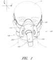
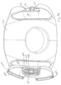
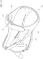
- an interface 100 is shown in position on a user U.
- the interface 1 00 comprises an interface that can be used in the field of respiratory therapy.
- the interface I 00 has particular utility with forms of positive pressure respiratory therapy.
- the interface 100 can be used for administering continuous positive airway pressure (“CPAP") treatments.
- CPAP continuous positive airway pressure
- VPAP variable positive airway pressure
- BiPAP bi-level positive airway pressure
- the interface can be used with any suitable CPAP system.
- the interface 100 can comprise any suitable mask configuration. For example, certain features, aspects and advantages of the present disclosure can find utility with nasal masks, full face masks, oronasal masks or any other positive pressure mask.
- the illustrated mask is a full face mask
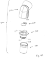
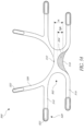
- the illustrated interface 100 generally comprises a mask assembly 102, a connection port assembly 104 and a headgear assembly 106.
- the mask assembly 102 generally comprises a mask seal 110, which can include a mask seal clip 112, and a mask base 114.
- the mask seal clip 112 preferably connects the mask seal 110 to the mask base 114. While the illustrated mask seal 110 and mask seal clip 112 are formed separately and secured together, in some configurations, the mask seal 110 and the mask seal clip 112 can be integrated into a single component. In some configurations, the mask seal 110 is overmolded onto the mask seal clip 112.
- the mask seal clip 112 is relatively more rigid, stiffer or more inflexible than the mask seal 110.
- the mask seal clip 112 is formed of a polycarbonate material.
- at least a portion of the mask seal clip 112 is formed of a polycarbonate or other rigid or semi-rigid material.
- the mask seal clip I 12 is formed at least partially of silicone or another suitable material. In such configurations, at least the silicone portion of the mask seal clip 112 may be formed to be relatively thicker compared to the more flexible portions of the mask seal 110.
- the mask seal clip 112 provides structural support to the mask seal 110 in the illustrated configuration.
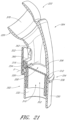
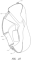
- the mask seal clip 112 can define a large portion of the mask assembly 102. As shown, the illustrated mask base 114 overlies a significant portion of the mask seal clip 112. With reference to Figures 25-27 , the mask assembly 102 can be configured with differing constructions, as desired. For example, with reference to Figure 25 , the mask seal clip 112 extends a limited amount from the interface with the mask seal 110. In the configuration illustrated in Figure 25 , the mask base 114 overlies at least a portion of the mask seal clip 112 while the mask seal clip 112 defines a very limited rimshaped configuration about a portion of the mask seal 110.
- the mask seal clip is omitted in its entirety and the mask seal 110 is overmolded directly onto the mask base 114.
- the mask seal 110 and the mask base 114 can be configured such that the two components can be separated.
- the mask seal 110 can comprise a peripheral flange 111 while the mask base 114 can comprise a peripheral channel 115 that receives the peripheral flange 111 such that the mask seal 110 can be removably secured to the mask base 114.
- other suitable manners can be used to secure the mask seal 110 to the mask base 114.
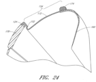
- the illustrated configuration of Figure 27 shows an embodiment without a mask seal clip 112, the mask seal clip 112 and the mask base 114 have been combined into the mask base 114.
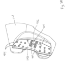
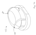
- the illustrated mask seal clip 112 comprises a substantially cup-shaped configuration.
- a proximal end 120 defines an open end of the illustrated mask seal clip 112 while a distal end 122 defines a generally closed end of the illustrated mask seal clip 112.
- the proximal end 120 is generally circumscribed by a lip 124.
- the lip 124 is generally pentagonal when viewed from the back (see Figure 5 ).
- a wall 126 generally sweeps forward in an arcuate manner. The arcuate shape to the wall 126 provides a three dimensional configuration to the illustrated mask seal clip 112.
- an upper portion 130 of the illustrated mask seal clip 112 is generally arcuate in configuration.
- the generally arcuate configuration of the illustrated mask seal clip 112 is configured to accommodate larger noses while not extending upward over the nose to as great an extend as the mask seal 110, as shown in Figures 1 and 2 .
- the upper portion 130 of the illustrated mask seal clip 112 preferably comprises two arcuate dimensions.
- an arc length 132 can be defined along an upper extremity of the upper portion 130 of the illustrated mask seal clip 112.
- the arc length 132 can be defined between inflection points 134 found along a perimeter of the illustrated mask seal clip 112.
- the upper portion 130 of the illustrated mask seal clip 112 also comprises a side profile radius 136.
- the upper portion 130 can have a slightly increasing side profile radius 136 such that the radius increases slightly as a distance from the upper end increases.
- the upper portion 130 can comprise a substantially constant side profile radius 136 or a decreasing side profile radius.
- the slightly increasing side profile radius 136 provides an increased volume in the mask 100 proximate the user's nose.
- the mask seal clip 112 preferably comprises at least two recesses 140.
- the mask seal clip 112 comprises two recesses 140 that are disposed on two lateral sides of a generally vellical center plane CP (see Figure 6 ).
- the generally vertical center plane CP preferably corresponds to a mid-sagittal plane of the user and splits the illustrated mask seal clip 112 into substantially mirror image halves.
- the two recesses 140 define two generally enclosed pockets in the illustrated mask seal dip 112.
- the illustrated recesses 140 comprise further recesses 142 that are used to provide adequate clearance for reasons that will be discussed below while limiting an amount of encroachment into a nasal region of a chamber defined by the mask assembly 102.
- the illustrated mask seal also comprises a generally central passage 144 that is defined by a wall 146.
- the wall 146 generally encloses the passage 144.
- the wall 146 is generally cylindrical in configuration and extends through the wall 126. Other configurations are possible.
- the mask seal 110 comprises a flexible portion that extends away from the proximal end 120 of the mask seal clip 112.
- the mask seal 110 is overmolded onto the mask seal clip 112 such that the mask seal 110 and the mask seal clip 112 combine to form an integrated and preferably non-separable assembly.
- attempts to separate the mask seal 110 and the mask seal clip 112 result in the destruction of the interface between the components and/or destruction of one or both of the mask seal 110 and the mask seal clip 112.
- other assemblies also can be used to connect the mask seal clip 112 to the mask seal 110.
- the illustrated configuration advantageously results in a construction that is easy to clean and maintain.
- the mask seal clip 112 preferably is arranged such that it is generally flush with an inner rim 150 of the mask seal 110.
- the mask seal 110 comprises a relatively small radius portion 152 that joins an upper portion 154.
- the upper portion 154 of the mask seal 110 is configured to extend over a nasal region of the user. In some configurations, the upper portion 154 is configured to extend over a nasal bridge region of the user U.
- the upper portion 154 is connected with a lower portion 156 of the seal member 110.
- the lower portion 156 extends laterally outward from the mask seal clip 112 as shown in Figure 9 .
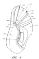
- the lower portion 156 wraps rearward and inward, as shown in Figures 4 and 10 respectively.
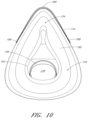
- the upper portion 154 and the lower portion 156 combine to define a face contacting flange 160, which is shown in Figure 10 .
- the face contacting flange 160 is configured to underlie a lower lip of the user, extend along the outside of the mouth, extend upward along the cheekbones and extend across the bridge of the nose of the user.
- the illustrated face contacting flange 160 defines a generally tear-drop shaped opening 162.
- the flange 160 will lie flat over the bridge of the nose, the cheekbones, the outside of the mouth and below the lower lip of the user.
- the mask seal 110 will balloon and seal against the face of the user to reduce or eliminate the likelihood of leakage between the flange 160 and the face of the user.
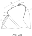
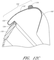
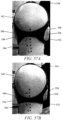
- the upper portion 154 of the mask seal 110 is designed to roll over onto an outer surface 170 of the mask assembly 102.
- the outer surface of the mask seal 110 smoothly rolls into abutment with the outer surface of the mask seal clip 112 such that the outer surface of the mask seal clip 112 forms a support surface.
- the outer surface 170 onto which the upper portion 154 rolls comprises at least a portion of the outer surface of the mask seal clip 112.
- the outer surface 170 onto which the upper portion 154 rolls comprises almost exclusively the outer surface of the mask seal clip 112.
- the upper portion 154 rolls onto another portion of the mask seal 110 In some configurations, the upper portion 154 rolls onto the mask seal base 114.
- the upper portion 154 can have a varying thickness or a varying stiffness.
- the upper portion 154 comprises a thick/thin/thick configuration.
- a reduced stiffness region 172 can be incorporated.
- the reduced stiffness region 172 is incorporated into the mask seal 110.
- the reduced stiffness region 172 reduces or eliminates the likelihood of the mask seal 110 buckling or adversely deforming in a region other than the desired region for rolling.
- the illustrated configuration uses a region of reduced thickness
- other means for providing the reduced stiffness region 172 also can be used to induce rolling of the seal member 110.
- the material of the seal member 110 can be configured to have a reduced stiffness through material selection or material properties.
- a composite of materials can be used to provide a region of reduced stiffness or rigidity.
- a combination of any suitable techniques can be used.
- the illustrated region 172 which is configured with reduced thickness, provides a simple manner of achieving the region of reduced stiffness 172.
- the force required to induce rolling of the region 172 can be controlled, which controls the force applied against the nose of the user. For example, by varying the stiffness, movement can become increasingly or decreasingly resisted over the range of movement.
- a reinforcing component or components such as a band 174
- the band 174 can be a component formed of a material that is more rigid than, or that features increased stiffness relative to, the silicone or other material forming the mask seal 110.
- a region of significantly increased thickness relative to the region of reduced stiffness 172, where the region is formed of the same material forming the mask seal 110 can be used to increase the stiffness of the reinforcing component or components.
- the band 174 can be a separately formed component that is at least partially encased by the material of the mask seal 110.
- the band 174 can be a comolded plastic component or the mask seal 110 can be overmolded onto the band 174.
- the band 174 can be defined by a portion of the upper portion 154 that has enhanced stiffness relative to surrounding regions.
- the band 174 can be defined by a portion of increased thickness, a portion of differing material or material properties that result in increased stiffness or the like.
- the band 174 extends along at least a portion of the upper portion 154 of the mask seal 110.
- the upper portion 154 of the mask comprises an apex 180 when viewed from the front.
- the apex 180 can be defined as a tip, a top and an angular summit of the mask seal 110, which apex 180 is positioned in proximity to the nose of the user when in use.
- a first wall 182 and a second wall 1 84 converge at the apex 180 in the illustrated configuration.
- At least a portion of the first wall 182 and at least a portion of the second wall 184 are reinforced by one or more components or structures, such as the band 174.
- the reinforcing component or components, such as the band 174 for example, reinforces at least a portion of the first wall 182 and at least a portion of the second wall 184.
- the reinforcing component or components, such as the band 174 for example, reinforces at least a portion of the first wall 182, at least a portion of the second wall 184 and the apex 180.
- the illustrated band 174 has a first end 186 and a second end 188 that is opposite to the first end 186.
- the band 174 can be formed separate of the mask seal clip 112 and attached to the mask seal clip 112 by one or more flexible components.
- the band 174 can be connected by a mechanical hinge structure to the mask seal clip 112.
- the first end 186 and the second end 188 are positioned on the same side of the hinge axis H as the apex 180.
- the first end 186 and the second end 188 are spaced away from the hinge axis H toward the apex 180.
- the bend 152 and the stiffer region (e.g., region of thicker cross section) adjacent to the region of reduced stiffness 1 72 help to initiate rolling of the region of reduced stiffness 172.
- a controlled buckling of the region of reduced stiffness 172 occurs with the assistance of the adjacent stiffer portions.
- positioning an edge of the relatively more rigid mask seal clip 112 adjacent to the bend 152 further helps to induce rolling in the reduced stiffness region 172.
- the region of reduced stiffness 172 is bounded by a first boundary and a second boundary, wherein the first boundary and the second boundary have an increased stiffness relative to the region of reduced stiffness.
- the first boundary is defined by or alongside the band 174 while the second boundary is defined by or alongside the bend 152.
- the second boundary can be defined by or alongside an edge of the more rigid mask seal clip 112.
- the second boundary can be defined along a portion of the mask seal 110 positioned between the mask seal clip 112 and the region of reduced stiffness 1 72,
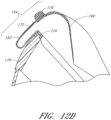
- the roll increases in size.
- a roll is formed in the mask seal 110.
- the roll continues to increase in size.
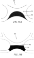
- the rolling between the first boundary and the second boundary creates a single bend or inflection between the first boundary and the second boundary.
- the single bend results in legs approaching the bend location that increase in size as the first boundary moves toward the second boundary.
- the rolling created by movement of the first boundary toward the second boundary preferably does not result in a fan-folding appearance such as a pleated configuration.
- the mask seal 110 can have a geometry that helps facilitate continued rolling of the region of reduced stiffness 172 following the initiation of the rolling.
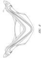
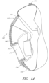
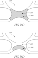
- Arc lengths can be defined in general from a first intersection of the hinge axis H with the mask seal 110, up and over the upper portion 154 of the mask seal 110, and back down to a second intersection of the hinge axis H with the mask seal 110.
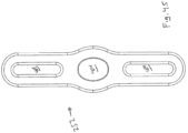
- the illustrated mask seal 110 comprises at least a first arc length A (shown in dashed line), a second arc length B (shown in dash-dot chain line) and a third arc length C (shown along a base of the band 174).
- the first arc length A preferably is longer than the arc length of the mask seal dip 112 directly adjacent to the first mask arc length A.
- the second arc length B is positioned between the first arc length A and the third arc length C and the second arc length B preferably is shorter than the third arc length C and longer than the first arc length A.
- the arc lengths steadily increase from the bend 152, or another region close to the outer surface 170, proximal toward the band 174.
- the arc length generally increases.
- the arc lengths can be substantially constant from front to rear (i.e., as the angle o. increases); however, by increasing the arc lengths away from the portion that initiates the roll, further movement of the apex 180 in a distal direction results in continued rolling of the mask seal 110 over itself and over the outer surface 170, as shown in Figure 11 .
- the upper portion 154 of the illustrated mask seal 110 also comprises a variable radius when viewed from the side profile. As shown, R1>R2>R3. Thus, in the illustrated mask seal 110, the radius decreases from proximal to distal as the angle increases. in some configurations, the radius need not decrease in this manner; however, the decreasing radius is believed to aid in rolling of the mask seal 110.
- a radius r1 of the mask seal clip 112 from the hinge point H preferably is smaller than the radius R3 of the mask seal 1 JO.
- the radius r1 and the radius R3 are substantially the same while still providing for the mask seal 110 to roll over the mask seal clip 112. in the illustrated configuration, however, the difference between the radius r1 and the radius R3 results in an offset
- the offset provides an ability to slightly increase the side profile radius 136, as described above, without significantly impacting the ability of the mask seal 110 to roll over the mask seal clip 112. If the offset were not provided, the ability to increase the side profile radius 136 would be very limited.
- hoop stress can be defined as circumferential stress in a cylindrically shaped part as a result of internal pressure.
- hoop stress increases as a ring attempts to expand.
- hoop stress resulting from seating a respiratory mask can be a source of some discomfort to the user, especially in the region of the bridge of the nose.
- the lower portion 156 of the illustrated mask assembly 102 generally is secured in position while the nasal or upper portion 154 moves relative to the nose of the user. Because of the rolling action described above, the illustrated full face mask assembly 102 acts to roll away from the nose, which decreases the incidence of increasing hoop stress, especially around the bridge of nose.
- the rolling mask configuration provides a means for maintaining or reducing hoop stress during seating of the mask.
- the upper portion 154 of the illustrated mask seal 110 rolls over the outer surface 170 in the illustrated configuration.
- the rolling over an external mask surface makes use of the positive pressure present within the full face mask assembly because the increased air pressure enhances the ability of the mask seal to roll on itself (i.e., the air pressure decreases a surface tension between the two surfaces of the mask seal that slide relative to each other during rolling) and the slight ballooning effect helps to reduce the likelihood of buckling, creasing or undesired folding of the mask seal 110.
- the external roll over can provide a visual cue of the degree or angle of displacement of the upper portion 154 of the mask seal 110 relative to the lower portion 156 of the mask seal 110.
- a scale can be imprinted, embossed or otherwise arranged on or near the reduced stiffness region 172.
- a scale can be positioned along a portion of the mask 100 over which the reduced stiffness region 172 will roll.
- the scale preferably is positioned in a central location such that the extent to which the reduced stiffness region 172 rolls can be maximized.
- the scale can be a numerical scale or a color gradient scale, for example but without limitation.
- a ratchet or lock mechanism can be integrated with the mask such that the reduced stiffness region 172 can be set at a desired roll point.
- a ratchet mechanism with a series of teeth that engage a closure member e.g., ziptie locking ratchets
- the lock mechanism enables the upper portion 154 to be retained in position when the mask 100 is removed from the face of the user U.
- the lock mechanism allows that locked position to be released easily as desired such that, if the mask is moved too far, the upper portion can be relaxed into a better fitting position.
- the user can set the extent to which the upper portion 154 rolls once and each subsequent use would result in the same level of roll.
- the upper portion 154 i.e., the portion of the seal member that contacts the bridge of the nose
- the force exerted by the upper portion 154 upon the bridge of the nose is substantially constant over a wide range of pressures exerted by the lower portion 156 against the rest of the face of the user.
- the force required to cause the upper portion 154 to move is substantially constant As shown in Figure 28 , the illustrated configuration results in a full 25 mm change in position of the upper portion with an increase of less than about 0.5 N of force associated with that range of movement.
- the force applied to the nose is generally constant over a range of angles and associated upper portion displacement, the force applied to the bridge of the nose does not vary significantly at various headgear tension levels. Again, such a result is shown in Figure 28 , wherein the total change in force over the range of 5 mm to 25 mm of movement at the apex 180 results in a force change of about 0.2 N.
- the mask can be adjusted to improve fitting to a variety of facial geometries while limiting the pressure exerted against the sensitive bridge of the nose region.
- the mask seal can be configured to roll inside the mask assembly.
- an internal roll over can be used in some configurations.
- the internal roll over is less desirable relative to the external roll over because the positive pressure tends to hinder rolling and because the rolling action tends to encroach into the chamber that receives the nose.
- the internal roll over provides a cleaner appearance relative to the external roll over because any ballooning of the seal member is contained within the mask seal clip.
- the mask assembly 1 02 includes the mask base 114, which is more rigid than the mask seal 110.
- the mask base 114 can be formed of any suitable material.
- the mask base 114 is formed of a polycarbonate material such that it is capable of flexing for connection with the mask seal 110 and/or the mask seal clip 112.
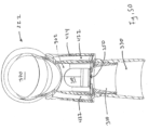
- the mask assembly 102 is shown with the mask base 114 secured to the mask seal 110. More particularly, in the illustrated configuration, the mask base 114 is secured to the mask seal clip 112 that is attached to the mask seal 110 in any suitable manner. In some configurations, the mask base 114 and the mask seal 110 or mask seal clip 112 are removably connected. In some configurations, the mask base 114 snaps together with one or both of the mask seal 110 and the mask seal clip 112. Preferably, the mask seal 110 and the mask seal clip 112 can be removed from the mask base 114 and a snap connection secures the mask seal clip 112 to the mask base 114.
- the illustrated mask base 114 overlies at least a portion of the mask seal clip 112. In some configurations, the mask base 114 almost entirely covers the mask seal dip 112. In some configurations, the mask base 114 extends over more than half of the mask seal clip 112. When the mask base 114 overlies a substantial portion of the mask seal clip 112 or the mask seal 110, a double layer effect is created (e.g., the mask seal clip 112 and the mask base 114). The double layer effect provides increased insulation when a significant portion of the mask base 114 overlaps a significant portion of the mask seal clip 112 or the mask seal 110.
- the increased insulation provides a warmer inner portion (e.g., mask seal 110 and/or mask seal clip 112), which results in less rain out of humidity during use.
- a portion of the mask seal clip 112 is exposed from under the mask base 114 such that the mask base 114 can be more easily separated from the mask seal clip 112.
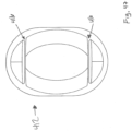
- the illustrated mask base 114 comprises a peripheral surface 200 on the proximal end.
- the mask base 114 is concave on the inside to accommodate the underlying components.
- the mask base 114 is bowl shaped in a distal direction relative to the proximal peripheral surface 200.
- the peripheral surface 200 comprises one or more recessed portions 202.
- the recessed portions 202 comprise at least two recessed portions 202 that are positioned on opposite sides of the mask base 114 from each other.
- the recessed portions 202 are configured to receive a thumb and a finger such that the mask base 114 can be more easily removed from the front of the underlying mask seal clip 112.
- the recessed portions 202 can define means for grasping the assembly underlying the mask base 114 for removal of the mask base, other configurations can be used, such as outwardly extending tabs, protruding portions and the like, for example but without limitation.
- the illustrated recessed portions 202 are disposed on opposing lateral sides of the mask base 114, the recessed portions 202 can be positioned on the top and bottom or on other regions as desired.
- the mask base 114 preferably comprises an opening 210 that is defined by a wall 212.
- the wall 212 that defines the opening 210 through the mask base 114 preferably fits within the wall 146 that defines the passage 144 through the mask seal clip 112.
- the wall 212 can be axially coextensive with the wall 146.
- the dimensions and shapes of the walls 146, 212 can be such that the walls interact with each other to reduce relative slippage between the walls 146, 212 and to reduce the likelihood of the mask seal base 114 inadvertently separating from the mask seal clip 112.
- the walls 146, 212 fit together and reduce the likelihood of leakage through the interface between the walls.
- a taper lock secures the walls 146, 212 together.
- the wall 212 comprises a contoured inner surface 214.
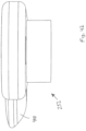
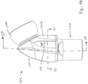
- the contoured surface 214 can be radiused to receive a ball end 220 of a swiveling elbow 222, such as that shown in Figure 17 .
- the ball end 220 has a contoured surface 224 that can be snap fit into the contoured surface 214 formed in the mask base 114.
- the connection between the two contoured surfaces 214, 224 allows the surfaces to slide relatively freely with each other such that the position of the swiveling elbow- 222 can be easily changed.
- the elbow 222 could be configured for rotation or swiveling without having a ball-joint configuration.
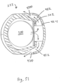
- the mask base 114 also comprises at least two pockets 230.
- the illustrated mask base 114 comprises two pockets 230.
- the pockets 230 recede into the mask base 114 and protrude rearward from the mask base 114.
- the pockets 230 are received within the recesses 140 of the mask seal clip 112.
- Overlying the further recesses 142 formed in the mask seal clip 112 are openings 232 that are defined by a surrounding wall 234.
- the illustrated pockets 230 are formed such that one pocket 230 is formed on each lateral side of the mask base 114.
- the pockets 230 can be positioned to be symmetrical relative to the central plane GP, which plane substantially bisects the mask base 114.
- the pockets 230 have an enlarged vertical dimension 240 relative to a transverse dimension 242.
- the openings 232 have an enlarged vertical dimension 244 relative to a transverse dimension 246.
- each pocket 230 comprises a support wall 250.
- the support wall 250 is positioned toward the center plane CP relative to normal to a base surface 248 of the pocket 230.
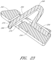
- Each of the pockets 230 is configured to receive a clip 252 (see Figure 22 ). Once the clip 252 is installed within the pocket 230, the support wall 250 helps to limit rotation of the clip 252 relative to the pocket 230. Moreover, the large vertical dimension helps users to locate the pocket 230 with the clip 252 during installation.
- the clip 252 can have a two part construction: an outer cover 254 and an inner catch 256. Straps 260 can be secured to each clip 252 in any suitable manner.
- One suitable configuration is illustrated in Figure 2 .
- the straps 260 can be sandwiched between the outer cover 254 and the inner catch 256.
- loops or openings or holes could be provided on the clips 252 through which the straps 260 are threaded.
- one clip 252 can be connected to both an upper strap and a lower strap of the headgear assembly 106. Such a configuration facilitates easy connection of the headgear assembly 106 to the full face mask assembly 102 and easy disconnection of the headgear assembly 106 from the full face mask assembly 102.
- the clip 252 comprises a sloping surface 262.
- the sloping surface 262 can be positioned on the outer cover 254.
- the sloping surface 262 cooperates with the support wall 250 to help orient the clip 252 relative to the pocket 203 of the mask base 114.
- the clip 252 includes an interlock feature 264.
- the interlock feature 264 is configured for insertion into the opening 232 defined in the pocket 230 of the mask base 114.
- the interlock feature 264 can engage in a snap-fit manner with a tab 236 defined along the wall 234 that defines the opening 232 in the mask base 114, as shown in Figure 13 .
- Other manners of interlocking the clip 252 with the pocket 230 also can be used.
- the interlock feature 264 of the illustrated clip 252 comprises a U-shaped component 268 that terminates in a release lever 266.
- the U-shaped end 268 protrudes a sufficient distance to allow the connection with the tab 236 but does not protrude so far as to allow the bottom of the further recess 142 in the mask seal clip 112 to stop proper insertion of the interlock feature 264 into the opening 232.
- the U-shaped end 268 initially makes contact with a wall of the opening 232 during connection of the clip 252 to the mask base 114. In the illustrated configuration, the U-shaped end 268 contacts the wall 234 of the opening 232 during insertion and the wall 234 guides the clip 252 into position within the pocket 230.
- the opening 232, or one or more surfaces that define the opening 232 generally align the clip 252 relative to the mask base 114 during connection of the clip 252 to the mask base 114.
- the end of the release lever 266 protrudes through an opening 270 defined by a wall 272.
- the end of the release lever 266 protrudes through the opening 270 a sufficient distance to allow easy manipulation of the release lever 266. Moving the release lever 266 in manner that closes the U-shape of the interlock feature 264 allows the interlock feature 264 to be removed from engagement with the tab 236 in the wall 234 that defines the opening 232 in the mask base 112.
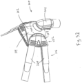
- Figures 32-39 illustrate additional configurations of clip assemblies 252 that are configured to secure a mask assembly 102 to a user's head.
- the clip 252 of Figures 32 and 33 for example has a raised edge 400 (sometimes referred to as a finger tab 400) that enables the user to easily detach the headgear 1 06 from the mask assembly 102.
- the raised edges 400 are oriented such that the user may merely pull them rearwardly to pop the clips 252 off the mask base 114. Removing one or more clips 252 from the mask base 114 allows the mask assembly 102 to be easily removed from the user's head.
- the raised edge 400 provides a grasping point during attachment and removal of the headgear 106 with respect to the mask assembly 102.
- the user's thumb and index finger may be placed on opposite sides of the raised edge 400 during removal of the clip 252 from the mask assembly 102.
- the user may grip the clip 252 and maintain the grip throughout the mask fitting process. This eliminates the need to grasp blindly for straps 260 during assembly. It also allows the user to attach the clip 252, remove it, and re-attach it while maintaining a grip on the raised edge 400.
- FIG 34 shows an exploded view of the clip 252 of Figures 32 and 33 .
- the clip 252 includes an outer cover 254 and an inner catch 256.
- the inner catch 256 includes one or more slots 402 to receive the distal end of the headgear straps 260.
- the inner catch 256 can also include several pressure bumps, such as those shown in connection with the configuration of Figures 38 and 39 . The pressure bumps provide additional pressure against the outer cover 254 and inner catch 256, so that they are secured to one another. in one configuration, the headgear straps 260 are removable from the assembled clip 252.
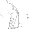
- the inner catch 256 includes an elongated slot 404, as shown in Figure 38 .
- the slot 404 includes a circular opening 406 having a diameter larger than the width of the slot 404.
- the slot 404 and circular opening 406 can include chamfered recesses to help align the clip 252 to the mask assembly 102.
- the circular opening 406 facilitates attachment and removal of the clip 252 to the mask assembly 1 02, as will be discussed in greater detail below.
- Two channels 408 extend parallel to the sides of the slot 404, thereby defining slot walls 410 (sometimes referred to as clip levers) on either side of the slot 404.
- the channels 408 are sized to permit adequate flexing of the slot walls 410 during attachment and removal of the clip 252 from the mask assembly 102.
- the slot walls 410 extend along the longest dimension of the inner catch 256, towards top and bottom, which allows longer slot walls 410 to be employed. Longer slot walls 410 reduce the level of stress on the slot walls when fitting the clip over the mounting
- FIG. 36 One configuration of a mask base 1 1 4 suitable for use with the clip 252 of Figures 32-35 is illustrated in Figure 36 .
- the mask base 114 includes two recesses 140 symmetrically positioned on opposite sides of the mask base 114.
- a mounting post 412 extends from the body of the mask base 114 within each recess 140.
- the mounting post 412 may be integrally formed with the mask base 114, or separately formed and secured to the mask base 114.
- the mounting post 412 can have a mushroom-shaped configuration to secure the clip 256 to the mask base 114 once the user snaps the clip 256 in place.
- the rounded top of the bulbous mushrooms-shaped post 412 helps locate and orient the central hole 406.
- the slot walls 410 deflect outwardly, away from the post 412. Once the head of the post 412 clears the edge of the slot wall 410, the slot walls 410 snap back to their original position, thereby providing tactile and sometimes audible feedback that the clip 252 is properly attached to the mask assembly 102.
- the mounting post 412 can also comprise an elongated, elliptical, elevated portion 414 (sometimes referred to as a lug or wing) that is sized to mate with the elongated slot 404 of the inner catch 256.
- the elongated, elevated portion 414 comprises a chamfered edge to help properly align the head gear 106 with respect to the mask assembly 102.
- the portion 414 also prevents the clip 252 from rotating with respect to the mask assembly 102. This helps assure constant tension on the headgear straps 260 while the user sleeps.
- Figure 37 illustrates a partial assembly of yet another configuration to secure a clip 252 to a mask base 114 of a mask assembly.
- the clip 252 sits within a recess 140 of the mask base 114.
- a cylindrical, button-head post 412 extends from the surface of the mask base 114 within the recess 140.
- the post 412 allows slight rotation of the clip 252 when attached thereto due to its cylindrical configuration.
- the slot 404, channels 408 and slot walls 410 extend along the shorter planar direction of the inner catch 256, towards its front and back ends.
- the inner catch 256 also includes several pressure bumps 414. As discussed above, the pressure bumps provide additional pressure against the outer cover 254 and inner catch 256, so that they are secured to one another.
- FIG. 40-47 Additional configurations of a clip 252 are illustrated in Figures 40-47 .
- the clip 252 of Figure 40 includes three elongated, elliptical slots 404 and a finger tab 400.
- the finger tab 400 is used to create a lever to release the clip 252 from a mask assembly 102.
- the central slot 404 is sized to receive a mounting post 412 that extends from the outside surface of the mask body.
- One such suitable mounting post 412 is illustrated in Figure 43 .
- the mounting post 412 includes a ridge 414 and two slots 416. As the clip 252 is pressed onto the mounting post 412, the outer portions of the post 412 flex towards each other due to the spacing provided by the slots 416. Once the ridge 414 clears the upper surface of the clip 252, the mounting post 412 snaps back to its original position, and the ridge 414 locks the clip 252 in place,
- FIG. 44-47 A similar configuration is shown in Figures 44-47 .
- the clip 252 of Figure 45 does not include a finger tab and its central opening 404 has a rounder, more elliptical shape than the elongated slots of Figures 40-44 .
- the clips 252 allow the headgear 106 to open up so that it is not a closed loop. By opening up, the headgear 106 may be swung around the head rather than forcing the user to pull his head through it.
- the headgear assembly 106 also comprises a back strap 280 and a top strap 282.
- Other head gear assemblies also can be used.
- the back strap 280 extends around the back of the head of the user U at a location generally above a nape of the neck but generally below the occipital protuberance.
- the back strap 280 forks into an upper arm 284 and a lower arm 286.
- the upper arm 284 arcs upward to a location above the ear of the user and then arcs downward to a location generally forward of the ear of the user.
- the lower arm 286 arcs downward to a location generally below the ear of the user and extends slightly forward of the ear.
- the straps 260 can be connected to the back strap 280 in any suitable manner.
- the straps 260 connect to the upper arm 284 and the lower arm 286 respectively.
- the upper arm 284 and the lower arm 286 are more rigid than the straps 260 such that the arms 284, 286 generally maintain shape as the headgear assembly 106 is being donned.
- each of the upper arm 284 and the lower arm 286 supports its own weight.
- each of the upper arm 284 and the lower arm 286 is structured to be tangle-free during donning.
- the arms 284, 286 have sufficient torsion stiffness to reduce the likelihood of twisting when being put on.
- the straps 260 connect to at least one of the upper arm 284 and the lower arm 286 at a location forward of the ear. Such a configuration helps the user to locate the straps 260 without much difficulty.
- the ends of the upper arms 284 and the lower arms 286 can comprise slots 290, 292 such that the straps 260 can be threaded through the slots 290, 292.
- the straps 260 can comprise an adjustment mechanism 294, such as a Velcro or buckle configuration.
- the adjustment mechanism 294 allows a force between the mask seal 110 and the face of the user U to be adjusted. Any suitable adjustment mechanism 294 can be used.
- the top strap 282 preferably is flexible and has an adjustable length.
- the top strap 282 connects to the upper arms 284 through a slot 296 and reduces the likelihood of the upper arms 284 sliding down the head of the user and contacting the ears of the user.
- the top strap 282 connects to the upper arms 284 at a location generally above the ears of the user.
- the straps 260 exert a force in the direction of the arrow F while they connect to the mask base 114 by movement in the direction C, which direction is generally normal to the direction of the force F.
- the straps 360 are tensioned by pulling forward and the clips 252 are connected to the mask base 114 by movement in a direction normal to the forward pull.
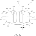
- the headgear assembly 106 includes a semi-rigid headgear 380 (as shown in Figure 29 ) to secure the mask assembly 102 to the user's head.
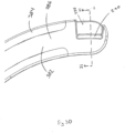
- the semi-rigid headgear 380 is formed as a composite structure comprising a semi-rigid strap 382 that is joined to a soft edging 384.
- the soft edging 384 can be bonded to the semi-rigid strap 382 by plastic overmolding or by use of an adhesive. As shown in Fig.
- the soft edging 384 can be butt-joined to the semi-rigid strap 382, without the soft edging 384 overlapping the semi-rigid strap 382, to maintain the continuous profile of the semi-rigid headgear 380.
- the semi-rigid strap 382 defines and maintains the semi-rigid headgear shape as tension is applied from the straps 260 to pull the mask assembly 102 towards the user's head.
- the semi-rigid strap 382 is sufficiently rigid along its planar axis to prevent its upper and lower arms 284, 286 from overly deforming under tension.
- the semi-rigid strap 382 can be made from a variety of rigid or semi-rigid materials, including plastic or metal. In some configurations, the semi-rigid strap 382 is made from PVC.
- connection and/or headgear members are selfsupporting such that they maintain a three-dimensional form
- the headgear can be fitted in the correct orientation with very little if any instruction.
- the tendency of the straps to not tangle also reduces the time taken to fit the overall assembly.
- the term "semi-rigid" is used to denote that the headgear assembly is sufficiently stiff such that the headgear assembly 380 can assume a three-dimensional shape with dimensions approximating the head of the patient for which the headgear is designed to fit while also being sufficiently flexible to generally conform to the anatomy of the patient.
- some of the other components (e.g., arms or straps) of the headgear assembly 380 may also be partially or wholly "semi-rigid” such that the components are capable of holding a three-dimensional form that is substantially self-supporting.
- a "semi-rigid" headgear assembly is not intended to mean that each and every component of the headgear assembly is necessarily semi-rigid.
- the substantially three-dimensional form that the self-supporting headgear assembly 380 may assume may relate primarily to the rear and top portions of the headgear assembly 380.
- the semi-rigid headgear assembly 380 may include semi-rigid regions that extend forward of the ears and above the ears when placed on the head of the patient
- the left and right upper and lower arms 284, 286 may be formed of a semi-rigid material, as well.
- the semi-rigid materials may include molded plastic or sheet materials that include but are not limited to homogeneous plastic materials and bonded non-woven fiber materials.
- one or more of arms or straps are formed of a substantially inelastic material.
- the arms or straps can be formed of a semi-rigid, self-supporting material such that the semi-rigid headgear assembly 380 can assume a substantially three-dimensional shape and generally does not tangle.
- the material can comprise a laminate structure of both comfortable and semi-rigid portions, for example but without limitation.
- the semi-rigid strap 382 may be of a self-supporting, resilient, substantially inelastic material, such as Santoprene, polyolefin, polypropylene, polyethylene, foamed polyolefin, nylon or non-woven polymer material for example but without limitation.
- the semi-rigid strap 382 is formed from the polyethylene or polypropylene families.
- the material can be a low density polyethylene such as Dowlex 2517, which is a linear low density polyethylene that has a yield tensile strength of 9.65 MPa, a break tensile strength of 8.96 MPa, and a flexural modulus - 2% secant of 234 MPa.
- the semi-rigid strap 382 preferably is formed of a material such that the semi-rigid headgear 380 is substantially shape-sustaining under its own weight regardless of its orientation. In some configurations, the semi-rigid strap 382 does not stretch more than approximately 6 mm under a 30 N tensile load. In some configurations, the semi-rigid strap 382 does not stretch more than approximately 3 mm under a 30 N tensile load.
- the semi-rigid strap 382 is formed from non woven polyolefin (NWP), which is bonded (e.g., overmolded or laminated) with a polyolefin.
- NWP non woven polyolefin
- the overmolded polyolefin material provides the principle shape sustaining properties.
- the softer NWP material is adapted to contact the skin and provide a desired comfort level.
- the NWP material may assist in providing the desired load bearing properties, such as the desired tensile load bearing properties.
- the semi-rigid headgear 380 is generally formed of a semi-rigid material.
- the semi-rigid materials may include molded plastic or sheet materials that include but are not limited to homogeneous plastic materials and bonded non-woven fiber materials.
- the upper and lower arms 284, 286 also include such semi-rigid materials, as the arms 284, 286 are formed integrally with and are portions of the semi-rigid headgear 380.
- the right and left lower arms 286 are formed as an integrated component that, in use, will extend around the back of the head and above the neck of the patient.
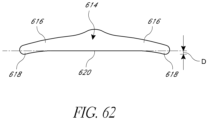
- a soft edging 384 covers or attaches to at least a portion of the periphery of the semi-rigid strap 382. In one configuration, the soft edging 384 does not cover the front or rear faces of the semi-rigid strap 382. For example, the thicknesses of the soft edging 384 and semi-rigid strap 382 can be the same at the location where they arc joined together.
- the soft edging 384 provides a soft, comfortable interface between the periphery of the semi-rigid strap 382 and the user's skin.
- the soft edging 384 can be made from a variety of soft materials, including but not limited to a plastic, an elastomer, silicone or thermoplastic polyurethane (TPU) plastic.
- the soft edging 384 can have a Shore hardness in the range of 1 0-80 Shore A.
- a strap including at least an element of "soft” and/or “conformable” material also may be “semi-rigid” and/or axially inelastic.
- the soft edging 384 can have a uniform thickness, or in some configurations, an uneven thickness.
- the soft edging 384 is the same thickness as the semi-rigid strap 382.
- the soft edging 384 is thinner than the semi-rigid strap 382, forms a bulbous end to the semi-rigid strap 382, or is simply thicker than the semi-rigid strap 382.
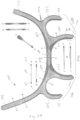
- a variety of cross-sectional views of the semi-rigid headgear 380 are shown in Figure 29 .
- Each cross-sectional view shows one possible configuration of semi-rigid strap 382 and soft edging 384 thicknesses, which may be combined as desired.
- any one particular soft edging 384 thickness and shape could apply to a portion or the entire semi-rigid strap 382, or may be combined with any other particular covering thickness and shape shown in Figure 29 .
- material thickness may be symmetrically or asymmetrically applied to the semi-rigid strap 382.
- cross-sectional views C-C' and F-F' are shown as asymmetric; however, in other configurations the thickness of either end the soft edging 384 is symmetrically applied to the semi-rigid strap 382.
- the semi-rigid strap 382 is selectively thickened to provide extra rigidity and support
- the second of the two configurations illustrated as cross-sectional view F-F' has such a thickening.
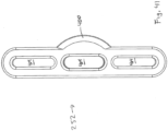
- venting through-holes 396 are provided throughout the semi-rigid headgear 380 (such as on the semi-rigid strap 382, as shown in Figure 29 , or on soft edging 384) to provide ventilation and sweat management.
- the semi-rigid headgear 380 When laid flat, as shown in Figure 29 , the semi-rigid headgear 380 defines three C-shaped, arcuate regions 386, 388, 390. Two ear-surrounding regions 386, 388 are defined by upper and lower arms 284, 286, and a rear region 390 is defined by lower arms 286 and the back strap portion 280.
- the semi-rigid headgear 380 is flexible enough to bend to adapt to the shape of the user's head, such that the ear-surrounding regions 386, 388 at least partially surround or encircle the user's ears, and the rear region 390 at least partially surrounds or encircles the back of the user's head, above the neck.
- each arm 280, 284, 286 can be selected to provide a comfortable fit and to facilitate application and removal of the semi-rigid headgear 380 from the user's head.
- the upper arms 284 have a concave curvature and the lower arms 286 have a convex curvature with respect to the opening in the upper ear surrounding arcuate regions 386, 388.
- the back strap portion 280 and the lower arms 286 all have a concave curvature with respect to opening in the neck surrounding arcuate region 390.
- the configuration of Figure 29 utilizes integrated crown straps comprising first and second crown arms 392, 394 to secure the semi-rigid headgear 380 to the user's head.
- first and second crown arms 392, 394 are brought into contact with one another to secure the semi-rigid headgear 380 in place.
- Any of a variety of mechanisms can be provided with the first and second crown arms 392, 394 to enable them to attach to one another.
- a hook-and-loop fabric e.g., Velcro
- one or more snaps or clips can be used to attach the first and second crown arms 392, 394 to one another.
- the crown straps extend laterally over the top of the skull in line with the ears.
- the back strap 280 of the semi-rigid headgear 380 should locate on or below the inion.
- the user's inion is the most prominent projection of the occipital bone at the posterioinferior portion of the skull. In other words, the inion is the highest point of the external occipital protuberance.
- the semi-rigid headgear 380 can be positioned on the user's head according to any of the configurations described in the attached Appendix, which forms an integral part of the present disclosure and is bodily incorporated, herein.
- the back strap portion 280 is adapted to engage with the rear of head of the user.
- the back strap portion 280 is adapted to engage with the head at a location on or below- the external occipital protuberance.
- the back strap portion 280 spans the distance around the back of the head and extends to each side of the head.
- the back strap portion 280 comprises a longitudinal center that is adapted to be located about 25 degrees below a horizontal plane that extends through the ear canal of the patient
- the semi-rigid headgear 380 extends upward and downward into left and right side regions that form arcuate regions 386, 388.
- the side regions are adapted to extend behind the ears of the patient
- the side regions also are adapted to extend behind the mastoid processes of the patient.
- Each of the left and right side regions of the semi-rigid headgear 380 extends into or comprises an arched portion 386, 388.
- the arched portions 386, 388 bend forward.
- the arched portions 386, 388 are adapted to extend around the respective ears of the patient.
- each of the arched portions 386, 388 terminates at a respective termination portion.
- the termination portions preferably are adapted to be located forward of the ears of the patient.
- the side regions and the arched portions 386, 388 of the semi-rigid headgear 380 do not include a soft inner padding portion but may comprise a self-supporting, resilient material that is in direct contact with the head/hair of the patient
- the top portion of the semi-rigid headgear 380 connects the arched portions 386, 388 together.
- the top portion can be positioned forward of the ears in some configurations.
- the top portion is positioned generally vertical from the ears. More preferably, a longitudinal center of the top portion is adapted to be spaced more than 13 mm, preferably between 13-100 mm, rearward of a vertical plane that intersects the ear canals.
- the top portion comprises a first segment 392 and a second segment 394 with the first segment 392 and the second segment 394 combining to form the top portion.
- the first segment 394 extends upward from an apex of the left arched portion 386 while the second segment 392 extends upward from an apex of the right arched portion 388.
- the top portion is formed of a self-supporting and semi-rigid material. In some configurations, the top portion does not include any backing, including a soft padded backing layer.
- Each of the upper and lower arms 284, 286 comprises a slot 292, 290 near each arm end.
- Each slot is configured to receive straps 260 from the mask assembly 102, as shown in Figure 2 .
- the portion 398 of the semi-rigid headgear 380 covered by straps 260 is thinner than the corresponding arm 284, 286 in order to accommodate the thickness of the strap 260.
- the semi-rigid headgear portion 398 is thinner than the arm 286.
- the portion 398 is dimensioned such that when the strap 260 is inserted into the slot 290 and tensioned, its thickness will not extend beyond the arm 286. By maintaining the thickness of the strap 260 and the portion 398 less than the thickness of the arm 286, the strap 260 does not irritate the user when worn.
- the upper arms 284 are configured to extend downward from a location above the user's ear such that the adjustable top straps 260 extend no closer than about 10 mm to the user's eye when worn.
- the lower arm 286 is configured to be located off of the user's neck when the head is tilted up and down, and the termination point of the lower arm 286 is located generally below the user's ears so that the lower strap as attached to the lower arm 286 angles upwards from the termination point 290 to the mask assembly 120.
- the lower straps and the upper straps form a triangle, and the space between the lower straps and the upper straps on the mask is smaller than the space between the lower straps and the upper straps on the headgear, thereby stabilizing the mask assembly 120 against upward and downward movements.
- the elbow- 222 connects to a conduit 300 through a disconnectable swivel assembly 302.
- the elbow 222 comprises a stem 304 that comprises an inner wall 306 at the base.
- the inner wall 306 comprises a recess 308.
- a sleeve 310 comprises a flange 312 that is received within the recess 308.
- the sleeve 310 can be secured into position within the elbow 222 using any suitable technique.
- the sleeve 310 comprises a generally cylindrical outer wall 314.
- the flange 312 comprises a section that extends outward to connect to a lever 316.
- the flange 312 and the lever 316 are integrally formed.
- the lever 316 includes a lower inwardly extending catch 320 and is capable of pivoting about the section that connects the lever 316 to the flange 312.
- a swivel 330 comprises a generally cylindrical inner wall 332.
- the inner wall 332 slides over the outer wall 314 of the sleeve 310 such that a sliding fit results between the swivel 330 and the sleeve 310.
- An upper portion 334 comprises a shoulder 336.
- the catch 320 of the lever 316 can secure the swivel 330 in axial position on the sleeve 310 by engaging with the shoulder 336. When the upper portion 322 of the lever 316 is depressed, the catch 320 moves away from the shoulder 336, which allows the swivel 330 to be removed from the sleeve 310.
- a flap 350 can be mounted between the stem 304 and the sleeve 310.
- the flap 350 extends into a flow channel 352 from a base 354 that is sandwiched between the stem 304 and the sleeve 310.
- the flap 350 can pivot upward (as shown in Figure 20 , see arrow P) about an axis X (see Figure 21 ) away from the sleeve 310 such that flow from a positive pressure generator can continue generally unobstructed to the user through the interface 100.
- the flap 350 pivots downward into contact with the sleeve 310 to seal the flow channel 352 in the event that the positive pressure source stops providing a pressurized flow of air.
- the flap 350 will not fully contact the sleeve 310.
- the flap 350 will not seal the channel 352 when in the down position.
- a port 360 is defined through the elbow 222 at a location above the flap 350.
- the port 360 preferably is positioned along a portion of the elbow 222 that is in the vicinity of the axis X. in some configurations, the port 360 is positioned to be substantially shielded by the Hap 350 from an inspiratory flow of air. In other words, as the air pivots the flap 350 away from the sleeve 310, the flap 350 is moved into a position that at least partially or completely covers the port 360.
- the port 360 extends through a wall of the elbow 222 that comprises a generally planar inner wall 362.
- the generally planar inner wall 362 helps the flap 350 to generally seal the port 360 when the flap is moved upward away from the flange 312 of the sleeve 310.
- the lever 316 overlies a majority of the port 360 such that the port 360 is generally obscured from view-. As shown in Figure 20 , however, a gap 364 preferably surrounds at least a portion of the lever 316 such that a relatively free flow of air can pass through the port 360 when the flap 350 does not overly the port 360.
- the port 360 and the lever 316 are positioned on a same side of the elbow 222 as an opening 370 defined within the ball end 220, which opening is positioned within the mask assembly 102 when the connection port assembly 104 is assembled to the mask assembly 102.
- such a positioning places the port 360 in a position on the elbow 222 that faces the user. Such a location further obscures the port 360 from view during use, which results in a more aesthetically pleasing configuration.
- flow through the port 360 will be very infrequent, having the port 360 disposed toward the user will not cause any significant discomfort for the user.
- the elbow 222 also can comprise one or more bias flow vent holes.
- the bias flow vent holes preferably are positioned in a forwardly directed orientation such that any bias flow does not directly impinge upon the user.
- FIG. 48-51 Another configuration of an elbow assembly 302 is illustrated in Figures 48-51 .
- the elbow assembly 302 comprises an elbow 222, a sleeve, 310, and/or a swivel 330, as shown in Figure 49 .
- the elbow assembly 302 only includes the elbow 222 and sleeve and omits the swivel 330.
- the swivel may be permanently or removably attached to the sleeve 310 and elbow 222; in some configuration, the swivel 330 is integrally formed with the end of the delivery conduit.
- a flap 350 is positioned over the sleeve 310 such that it at least partially obstructs the sleeve's flow channel 352.
- the elbow assembly 302 functions similarly to the elbow assembly 302 of Figures 17-21 ; however, the elbow assembly 302 of Figures 48-51 provides the additional benefit of directing gases away from the patient when the flap 350 drops to its closed position (as shown in Figures 50 and 51 ).
- the sleeve 310 preferably comprises two or more cut out regions or recesses 356.
- the recesses 356 can have any suitable shape and, in the illustrated configuration, the recesses 356 comprise a semicircular configuration that extends upward into the sleeve 310.
- the sleeve 310 also comprises at least one bump 357, and preferably two or more bumps 357.
- each of the bumps 357 extends around an arc of about 70 degrees. More preferably, each of the bumps 357 is generally centered between two recesses 356 and each of the bumps 357 extends about 70 degrees around an outer surface of the sleeve 310.
- the swivel 330 preferably is generally cylindrical in configuration. As shown in Figure 49 , the swivel 330 has an inwardly extending ridge 358.
- the ridge 358 preferably encircles the entire inner surface. in some configurations, the ridge 358 can be interrupted. Preferably, however, the ridge 358 does not have any interruptions large enough to accommodate the entire bump 357 such that the ridge 358 and the bump 357 can cooperate to keep the swivel 330 mounted over the sleeve 310.
- the recesses 356 allow the bumps 357 to deflect inward such that the bumps 357 can slide over the ridge 358 and then snap back outward to secure the bumps 357 under the ridge 358.
- the elbow 222 comprises openings 420 at its sides that are in fluid communication with an air venting channel 422.
- the air venting channel 422 is formed by the spacing between the elbow's inner and outer walls 362, 424, as shown in Figures 50 and 51 .
- Figures 48-51 provides a reduced overall length and improves product aesthetic by eliminating an unsightly hole positioned at the front of the elbow 222.
- the configuration of Figures 48-51 and improves patient comfort by preventing air from being directed towards the user. Instead, openings 420 direct air flow out of the sides of the elbow 222 and away from the patient.
- a flexible headgear assembly 500 can be used to secure a mask assembly to a user's head for respiratory therapy, for example but without limitation.
- the illustrated flexible headgear assembly 500 can be used with any suitable mask assembly, including but not limited to any of the mask configurations disclosed herein.
- the illustrated flexible headgear assembly 500 comprises a back strap portion 502. At least a portion of the back strap portion 502 is joined with a panel 504. In the illustrated configuration, the back strap portion 502 is configured to span a distance around the back of the user's head and is configured to extend toward each lateral side of the user's head.
- a pair of upper arms 506 and a pair of middle arms 510 can extend generally transversely from a top edge 512 of the back strap portion 502.
- a pair of lower arms 514 can extend generally transversely from a lower edge 516 of the back strap portion 502.
- the pair of lower arms 514 extend down and away from the back strap portion 502 such that a lower edge of the lower arms 514 will be positioned lower than the bottom edge of the back strap portion 502.
- the pair of middle arms extend upward and away from the back strap portion 502 such that the middle arms 510 have an upper edge that is positioned higher than the upper edge of the back strap portion.
- the lower arms 5 I 4 and the middle arms 510 terminate with ends 520 in the illustrated configuration.
- the ends 520 can comprise securing portions 522, which can be formed of hook or loop components for a hook-and-loop style fastening arrangement
- the securing portions 522 comprise at least hook portions that can engage with the material of another portion of the headgear assembly 500.
- Each of the upper arms 506 also can terminate with regions comprising a securing portion 524.
- the back strap portion 502 When positioned on the head of a user, the back strap portion 502 is located on or below the external occipital protuberance and above the nape of the neck of the user.
- the upper straps 506 can be connected together in any suitable manner. In some configurations, a clip secures the upper straps 506 together with the securing portion 524 doubled back and secured to another portion of the upper straps 506. Thus, the upper straps 506 can extend generally over a top of the head of the user to limit downward movement of the balance of the headgear assembly 500.
- the middle arms 510 and the lower arms 514 can be connected to a clip (not shown) or another portion of the mask assembly such that the middle arms 510 and the lower arms 514 secure the headgear assembly 500 to the mask either directly or indirectly (e.g., with a clip, such as that shown in Figure 40 , for example but without limitation).
- the ends 520 of the middle arms 510 and the lower arms 514 can be passed through loops or other structures on the mask assembly and doubled back with a fold.
- the overlapping portions can be secured in any suitable manner.
- the overlapping portions can be secured with a hook-and-loop fastening arrangement (e.g., Velcro ® ) fasteners).
- At least one of the end portions of the upper arms 506, the middle arms 510 and the lower arms 514 can comprise enlarged ends 520.
- the enlarged ends 520 are formed on at least the middle arms 510 and the lower arms 514 of the flexible headgear 500.
- the enlarged ends 520 can be found on one or more arm that connects to the mask assembly.
- the enlarged ends 520 can be integrally formed with the main portion of the arms 510, 514.
- the arm 526 can be formed integrally with the enlarged end 520.
- the illustrated enlarged end 520 has a width d while the arm 526 has a width e.
- the width e of the arm 526 can be between about 12 mm and about 20 mm, between about 14 mm and about 18 mm, or preferably about 16 mm.
- the width d of the enlarged end 520 can be between about 18 mm and about 26 nun, between about 20 mm and about 24 mm, or preferably about 22 mm.
- the difference between the largest width d of the enlarged end 520 and the arm width e is between about 3 mm and about 10 mm, or between about 5 mm and about 8 mm.
- the difference between the largest width d of the enlarged end 520 and the arm width e is about 6 mm. Because the width d of the enlarged end 520 is greater than the width e of the arm 526, an edge of the enlarged end 520 can more easily be located such that the portion used to secure the end 520 to the arm can be more easily located in order to refit the arm 526 (e.g., in order to tighten, loosen, remove, or otherwise reposition the flexible headgear 500).
- a neck portion 536 can be formed at a location between the enlarged end 520 and the arm 526.
- the neck portion 536 can provide reduce the likelihood of the enlarged end 520 sliding out of the attachment portion on the mask assembly when secured to the user's head.
- an opening in the attachment portion on the mask assembly may be about 16 mm to about 18 mm wide while the enlarged end 520 may be about 22 mm and the arm 526 may be about 16 nun. Accordingly, the likelihood of the enlarged end 520 inadvertently pulling through the opening is greatly reduced.
- the geometry of the neck portion 536 can further reduce the likelihood of the enlarged end 520 inadvertently pulling through the opening. Any suitable transition can be used. As illustrated in Figure 56 , the neck portion 536 can be curved to facilitate removal of the arm from the mask assembly, when desired. The neck portion can extend at an angle between about 0 degrees and about 90 degrees relative to the arm. Preferably, the neck portion 536 extends at an angle of between about 20 degrees and about 60 degrees. In some configurations, the neck portion 536 can be a more abrupt transition or a less abrupt transition. The more abrupt the transition, the less likely the arm will inadvertently separate from the mask assembly.
- the neck portion 536 forms a portion of the geometry of the enlarged end 520.
- the enlarged end 520 can be substantially oval-shaped.
- the enlarged end 520 can be configured to resemble various shapes, including, for example, a parallelogram, an ellipse, a circle, a triangle, or any other suitable shape.
- each of the enlarged ends 520 can comprise an embedded panel 522 having hook fasteners or the like.
- the panels 522 can be located on the enlarged ends 520 such that the enlarged ends 520 can be secured to another portion of the corresponding arm when the arm has been folded back over itself.
- the embedded panels 522 can be comprised of a hook-fabric (e.g., Velcro ® ).
- Velcro ® a hook-fabric
- the panels 522 can be attached to the ends of the arms in any suitable manner.
- the panel 522 is attached to the enlarged end 520 by ultrasonic welding.
- the panel 522 can be located in a desired location along the arm and then the ultrasonic welding process can effectively melt the two materials together.
- a weld edge 530 having width a is formed around a perimeter of the enlarged hook-fabric panel 522.
- a width a of the weld edge 530 is approximately 3 mm.
- An area of the hook-fabric panel 522 that comprises the weld edge 530 generally is not functional to engage hook-receptive materials as a result of the ultrasonic welding procedure melting or otherwise deforming the hooks of the hook-fabric. Thus, a functional surface area of the hook-fabric panel 522 is decreased by a surface area equal to that of the weld edge.
- the weld edge 530 can be bound by a soft edge 532 having width b comprised of the hook-receptive breathable composite materials of the enlarged end 520.
- the weld edge 530 is recessed below the surface of the soft edge 532.
- a projection of the width e of the arm 526 can extend through the weld edge 530 such that the soft edge 532 would be positioned slightly outward of the projection of the width e of the arm 526.
- the width b of the soft edge can be from about 0.5 mm to about 4 mm, from about 1 mm to about 3 mm, or preferably about 2mm.
- An active hook portion 534 can adjoin the weld edge 530 and have a width c.
- the width c of the active hook portion can be slightly narrower than the width e of the arm 526. By increasing the width c , the functional surface area of hook-fabric material can be increased, thus improving a sheer force resistance and durability. By having the width c smaller than the width e of the arm 526, the arm 526 reduces the likelihood of the active hook portion 534 contacting the skin of the user.
- the width c of the active hook-fabric portion 534 can be from about 8 mm to 16 mm, from about 10 mm to about 14 mm, or preferably about 12 mm.
- the enlarged end width e enables the width c of the functional surface area to be increased. In other words, the end of the arm has been enlarged such that the width of the active hook portion 534 can be increased, which can provide a more secure attachment of the enlarged end to the surface of the arm.
- the flexible headgear assembly 500 can be formed of any suitable material.
- the flexible headgear assembly 500 can be covered with or have at least some portion formed of a hook-fastener receptive breathable composite material.
- the flexible headgear assembly 500 can be at least partially formed of Nylon/Lycra Breath-O-Prene ® material.
- Nylon/Lycra Breath-O-Prene ® material when a 150 mm long by 20 mm ⁇ vide sample of the material is subjected to a 10 N axial load, the sample elongates to about 207 mm, which is an elongation of about 38% caused by the 10 N axial load.
- the material preferably is fairly elastic.
- the headgear assembly 500 can comprise one or more rounded edges.
- the rounded edges can be formed in any suitable manner. In some configurations, the rounded edges are formed by applying heat and pressure to the edges of the headgear assembly 500. In some configurations, the rounded edges are formed in a manner similar to the techniques described in U.S. Patent No. 3,295,529 .
- the back strap portion 502 of the illustrated flexible headgear assembly 500 preferably comprises at least one relatively inelastic panel 504.
- the panel can be formed of a relatively low-stretch material, such as a polyester Breath-O- Prene ® material, for example but without limitation.
- a relatively low-stretch material such as a polyester Breath-O- Prene ® material, for example but without limitation.
- the sample when a 150 mm long by 20 mm wide sample of the material is subjected to a 10 N axial load, the sample elongates to about 160 mm, which is an elongation of about 7% caused by the 10 N axial load.
- the material preferably is fairly inelastic or non-stretch when compared to the more elastic material of the flexible portion.
- the panel 504 is formed of a less elastic material than the surrounding portions of the headgear assembly 500, the panel 504 resists stretching in at least a portion of the headgear assembly 500. By resisting elongation of at least a portion of the otherwise elastic headgear assembly, the panel helps maintain the headgear 500 in a desired shape and helps maintain the headgear 500 at a desired location relative to a back of the user's head.
- Figures 57A and 578 illustrate the effect of applying increasing force to the lower arms 514 of the flexible headgear 540 with a back strap portion 544 completely comprised of an elastic material.
- the illustrated configuration in Figures 57A and 578B do not feature the panel 504.
- the back strap portion 544 is positioned in a desired location when it is located on or below the external occipital protuberance and above the nape of the neck of the user.
- the back strap portion 544 is shown in a more preferred position.
- position markers 546 are shown on the testing model 542.
- the elastic nature of the back strap portion 544 allows it to elongate and deform, which allows the back strap portion 544 to move downward along the neck of the user.
- Reference to the position markers 524 illustrates the movement. With downward movement, more force from the back strap portion 544 is applied to the neck rather than the head, which is less desired. Because the flexible headgear 540 can be worn for a period of minutes to hours, or for a period of hours to days when used for respiratory therapy, the lowered positioning of the back strap portion 544 can create discomfort for the user.
- the less-elastic panel 504 can be attached to the back strap portion 502.
- the panel 504 can comprise of a substantially non-stretch insert 560.
- the insert 560 can be attached to the back strap portion 502, for example, by over-lock stitching, by ultrasonic welding, by use of glue or other adhesives, or by any other method known to those of skill in the art.
- the insert 560 can provide a greater tension resistance, which allows a greater force to be applied to the lower arms 514 when attaching and using the flexible headgear 500.
- the insert 560 can advantageously reduce deformation of the back strap portion 502 and aid in keeping it located in a desired position relative to the head and neck of the user.
- the non-stretch inse1i 560, 562, 564, 566 can be configured in a variety of shapes, including but not limited to those shown in Figures 58A-58D .
- the non-stretch inse11 560, 562, 564, 566 adjoins or covers at least the backstrap portion 502.
- the non-stretch insert 562, 564 adjoins or covers at least a portion of the lower arms 514.
- the non- stretch insert 562, 564 adjoins or covers at least a portion of a junction between the lower arms 514 and the backstrap portion 502.
- the non-stretch insert 564 adjoins or covers at least a portion of the middle arms 510. In some configurations, the non- stretch insert 564 adjoins or covers at least a portion of a junction between the middle arms 510 and the backstrap portion 502. In some configurations, a height of the non-stretch insert 560 is at least about half of a height h of the back strap portion 502. In some configurations, the height of the non-stretch insert 560 is preferably more than about half of the height h of the back strap portion 502. By leaving a portion of the back strap portion 502 formed of the more elastic material, the back strap portion 502 is able to stretch and conform in a limited degree but more than would be possible with a back strap portion folly formed from a less elastic material.
- the non-stretch insert 560 can be configured to have any suitable surface area.
- the non-stretch insert 560 can be configured to extend along varying lengths of the lower edge 516 of the back strap portion 502. In some configurations, the non-stretch insert 560 extends along more than half of the lower edge 516 of the back strap portion 502. Preferably, the non-stretch insert 560 extends along substantially all of the lower edge 516 of the back strop portion 502. Other configurations are possible.
- an assembly comprising headgear 600 having two or more straps that can be connected with a winged buckle 602.
- the headgear 600 can be used with any suitable mask assembly, including but not limited to any of the mask configurations disclosed herein.
- the illustrated configuration comprises straps that are connected by a winged buckle 602 and such a configuration can be used with any of the headgear disclosed herein, for example but without limitation.
- the headgear assembly 600 comprises at least a pair of upper arms 606. Each of the upper arms 606 can terminate with ends 608. In some configurations, at least one of the pair of upper arms 606 comprises a securing portion, such as any of the securing portions described elsewhere. In the illustrated configuration, each of the upper arms 606 comprises a securing portion. Preferably, the securing portions are positioned at least partially on the ends 608. In some configurations, the securing portions can be formed of hook or loop components for a hook-and-loop style fastening arrangement. Preferably, the securing portions comprise at least hook portions that can engage with the material of another portion of the headgear assembly 600.
- the upper arms 606 can be joined by the winged buckle 602, for example but without limitation.
- the winged buckle 602 can comprise a body 610 that defines at least one slot 612, and preferably at least two slots 612.
- the at least one slot 612 accommodates the ends 608 of the straps 606 such that the ends 608 of the straps 606 can be passed through the at least one slot 612 and then folded over and secured in position with the securing portions as described above.
- the body 610 of the illustrated buckle 602 comprises a tri-glide slide connector portion 614 and a pair of wings 616. Accordingly, the at least one slot 612 can be defined by the tri-glide slide connector portion 614. In some configurations, however, the at least one slot 612 can be formed by one or more of the following (including multiples of one or more of the following components): a loop, a square ring, a D-ring, an oval ring, a sliplock buckle, a ladder lock or the like.
- the wings 616 advantageously provide support to the straps 606 such that, as shown in Figure 59 , the headgear assembly 600, including the straps 606 can substantially maintain a three dimensional shape.
- a buckle without wings will allow folding and flopping of the headgear assembly and more particularly the straps 606 about the buckle, which can cause the headgear assembly to not substantially maintain a three dimensional shape. Accordingly, the wings 616 have been found to enhance usability of the headgear assembly 600.
- laterally outward extents 618 of the wings 616 extend downward beyond a lower surface 620 of the connector portion 614.
- the buckle 602 can better conform to and/or follow a crown of a head of a user relative to a flat buckle.
- the laterally outward extents 618 may not extend downward below the lower surface 620 and/or the bottom of the buckle, including the wings, may be substantially flat or rounded.
- the buckle 602 can be formed of any suitable material.
- the buckle 602 can comprise two or more different materials such that the connector portion 614 can be formed of a more rigid material while at least the wings 616 can be formed of a softer material.
- the softer wings 616 can improve comfort while the more rigid connector 614 enables the buckle 602 to carry the loads that are expected to be experienced in the headgear assembly 602.
- the two or more different materials can be overmolded or comolded to form the buckle 602.
- the two or more different materials can be mechanically connected (e.g., snapfit, keyed or the like) or can be joined by cohering, adhering, or the like.
- at least the wings 616 can be formed of a thermoplastic elastomer or an impact-modified polyethylene, for example but without limitation.
- the connector portion 614 can be formed from a nylon or the like, for example but without limitation.
- the connector portion and the wings can be formed from materials having the same base material (e.g., materials that have suitable chemical relationships to allow joining of the materials).
- the wings 616 preferably generally taper in thickness from the region proximate the connector portion 614 toward the lateral extents 616. While any suitable tapering profile can be used, the reduction in thickness facilitates flexure of the wings 616 to enable better conformity to the anatomy of the user. In other words, the reduced thickness of the wings 616 at locations laterally outward from the portion adjoining the connector portion 614 results in a weaker flexural strength, which helps conformity to the anatomy of the user.
- the wings 616 have side walls 622 that taper inward.
- the inwardly tapering side walls 622 join to end walls 624 with rounded corners 626 in the illustrated configuration.
- the rounded corners 626 improve user comfort while the tapering side walls 622 reduce the width of the wings 616.
- the reduced width of at least the ends of the wings 616 facilitate capturing the wings 616 within the folded regions of the straps 606 underneath the ends 608, which is best shown in Figure 59 and Figure 60 .
- the folded ends 608 and/or the adjoining portion of the straps 606 define a pocket that receives the tapering ends of the wings 616.
- the straps 606 can widen in a region as discussed above.
- the connector portion 614 of the buckle 602 is wider than at least a portion of the strap 606 such that the strap 606 can extend through the opening 612 defined in the connector portion 614 while the wings 616 taper such that the strap 606 can overlie and/or envelope the wings 616.
- the wings 616 extend away from the connector portion 604 a length L2 that is greater than twice the thickness L1 of the wall of the connector portion 604 defining the slot 612. Other configurations also are possible. As discussed above, the extended length L2 of the wings 616 reduces flop over of the straps 606 when connected with the winged buckle 602.
- the wings 616 can have a length L2 that is less than a length of the connector portion of the ends 608 such that lateral extents 618 of the wings 616 can be enveloped by the connector portion of the ends 608.
Description
- The present disclosure generally relates to face masks that cover at least one of a nose and a mouth of a user to supply respiratory gas under positive pressure. More particularly, certain aspects of the present disclosure relate to such masks that have a nasal bridge seal portion that moves relative to another seal portion of the mask.
- Face masks can be used to provide respiratory gases to a user under positive pressure. In configurations in which both a mouth and a nose of a user are covered, the full face mask typically will overlie a bridge of the nose. Generally, a single seal will circumscribe the nose and the mouth of the user.
- Such full face masks commonly are secured to a head of the user with headgear. In order to sufficiently reduce leakage, the headgear typically is tightened, which results in an elevated pressure being exerted on a bridge of a user's nose. In other words, as the headgear is tightened, the silicone seal typically applies a progressively increasing load on the bridge of the nose. The pressure can be a source of discomfort and, in some circumstances, can lead to pressure sores over time. Patent document
US2003/127101 discloses respiratory masks. - The invention is defined by the appended claims. It is an object of the present disclosure to provide one or more constructions and/or methods that will at least go some way towards improving on the above or that will at least provide the public or the medical profession with a useful choice.
- Accordingly, an interface is provided for use in providing positive pressure respiratory therapy. The interface comprises a mask assembly. The mask assembly comprises a mask seal and a mask base that is removably connected to the mask seal. The mask seal comprises a mask seal clip that is more rigid than at least a portion of the mask seal. The mask seal clip is generally cup-shaped in configuration with an open proximal end and a generally closed distal end. A generally pentagonal lip extends around the proximal end. The mask seal clip comprises an arcuate upper portion with an outer surface. A mask seal clip arc length is defined along the outer surface adjacent an upper extremity of the upper portion between a pair of hinge points. A hinge axis extends laterally across the mask assembly between the hinge points and at least a portion of the upper portion of the mask seal clip is positioned vertically higher than the hinge axis. The mask seal clip upper portion comprises a support surface. A generally central passage extends through the mask clip into a chamber defined by the mask seal. The mask seal comprises a flexible upper portion that is configured to be positioned over a nasal region of a user. The mask seal upper portion is positioned vertically higher than the hinge axis. The mask seal upper portion comprises a region of reduced stiffness located between two regions of increased stiffness. The region of reduced stiffness is capable of rolling to allow pivoting of the mask seal upper portion relative to the mask seal clip. One of the two regions of increased stiffness is positioned adjacent to a small radius bend and the other of the two regions of increased stiffness is position adjacent to a reinforcing component. The small radius bend and the reinforcing component define boundaries between which the upper portion of the mask exhibits rolling during pivoting of the upper portion about the pivot axis. The mask seal upper portion has a first curve length adjacent to the small radius bend and a second curve length adjacent to the reinforcing band. The first curve length can be smaller than the second curve length. The curve length increases as a measured location moves away from the mask seal clip. The mask base overlies at least a portion of the mask seal clip. The mask base comprises a first pocket and a second pocket. The first and second pockets are positioned symmetrically relative to a center plane that substantially bisects the mask base. Each of the first pocket and the second pocket comprises a vertical dimension that is larger than a transverse dimension. The mask base also comprises a wall that defines a central opening. The wall extends into the generally central passage of the mask seal clip. A connection port assembly comprises an elbow terminating in a ball shaped member. The ball shaped member is sized and configured to be held by the wall that defines the central opening. The connection port assembly also comprises a removable swivel member. The removable swivel member is secured by a lever, The lever overlies a port. The port is selectively coverable with a flap. The flap also is capable of closing a central passage within the elbow. The port opening is in a general direction of the mask when the elbow is connected to the mask. A headgear assembly comprises a pair of upper straps and a pair of lower straps. One of the pair of upper straps and one of the pair of lower straps is connected to a first clip. Another of the pair of upper straps and another of the pair of lower straps is connected to a second clip. The first clip and the second clip are securable within the pockets of the mask base such that the clips are brought into engagement within the pockets by moving in a direction substantially normal to a strap tensile force direction.
- In some configurations, the mask seal is a full face mask.
- In some configurations, the mask seal clip is integrated into the mask seal such that the mask seal clip is non-separable from the mask seal.
- In some configurations, the mask base is removably connected to the mask seal.
- In some configurations, an outer surface of the upper portion rolls onto the support surface of the mask seal clip and the support surface defines an outer surface of the upper portion of the mask seal clip.
- In some configurations, the region of reduced stiffness comprises a region of reduced thickness compared to the regions of increased stiffness.
- In some configurations, the upper portion of the mask seal comprises an apex defined by a first wall and a second wall and the reinforcing component extends along at least a portion of the first wall and along at least a portion of the second wall Preferably, the reinforcing component extends over the apex of the upper portion of the mask seal.
- In some configurations, the reinforcing component ends at both ends in a location generally vertically higher than the hinge points.
- A mask assembly can comprise a mask seal. The mask seal comprises an upper portion and a lower portion. The upper portion is pivotable relative to the lower portion. The upper portion comprises a region of reduced stiffness that is positioned between a first boundary and a second boundary. The first boundary is defined by a stiffness greater than that in the region of reduced stiffness. The second boundary is defined by a stiffness greater than that in the region of reduced stiffness. When the first boundary is moved toward the second boundary, the region of reduced stiffness buckles in a single direction to define a roll of material that changes in size as the first boundary continues to move toward the second boundary.
- In some configurations, the region of reduced stiffness facilitates movement of the upper portion of the seal member relative to the lower portion of the seal member. Preferably, the upper portion comprises a nasal bridge portion of the mask and movement of the first boundary toward the second boundary facilitates movement of the nasal bridge portion of the mask relative to the lower portion of the mask
- In some configurations, the second boundary is positioned between the upper portion and the lower portion. Preferably, the mask further comprises a mask seal clip that has an increased rigidity relative to the mask seal and the second boundary is positioned along an end of the mask seal clip. More preferably, the roll of material overlies at least a portion of the mask seal clip.
- In some configurations, the first boundary is defined along a reinforcing component. Preferably, the reinforcing component comprises a plastic band.
- In some configurations, the region of reduced stiffness is defined with a reduced thickness relative to the first boundary.
- In some configurations, the second boundary is defined by a corner having a small radius.
- In some configurations, the roll extends over at least a portion of the mask seal.
- In some configurations, the roll overlies at least a portion of the mask seal clip when the first boundary is moved fully toward the second boundary.
- A mask assembly can comprise a mask seal. The mask seal comprises a nasal region and an oral region. The nasal region and the oral region are integrally formed. The nasal region is movable relative to the oral region such that forces exerted by the nasal region in multiple positions remain substantially constant while forces exerted by the oral region increase.
- A mask assembly comprises a mask seal connected to a headgear assembly. The mask seal is configured to encircle a nasal bridge region and an oral region of a user. The mask seal comprises nonpleated means for applying a substantially constant force to the nasal bridge region while applying increasing forces to an oral region when the headgear assembly is tightened.
- A mask assembly comprises a seal. The seal comprises a flange that engages a face of a user. The seal is removably connected to a mask base. The mask base comprises a first opening and a second opening. The first opening and the second opening receive a first clip and a second clip from an associated headgear assembly. The mask base further comprises a passageway positioned generally between the first opening and the second opening. The passageway is adapted to receive a breathing tube connector.
- In some configurations, the mask assembly further comprises a mask seal clip that is connected to the mask seal and that is removably connected to the mask base. Preferably, the mask base overlies a substantial portion of the mask seal clip. More preferably, the mask base comprises a peripheral edge and at least one recess is defined along the peripheral edge of the mask base at a location that overlies the mask seal clip.
- A mask assembly comprises a mask seal. The mask seal comprises a proximal flange adapted to contact a face of a user. The mask seal comprises a distal facing surface. A mask base comprises a peripheral edge and a cover surface extends from the peripheral edge. The mask base cover surface overlies at least a portion of the distal facing surface of the mask seal such that the mask base cover surface is spaced apart in a distal direction from the mask seal distal facing surface whereby the mask base cover surface and the mask seal distal facing surface provide an insulating effect to the mask assembly that reduces humidity rainout.
- A headgear assembly is configured to secure a mask assembly to a user's head. The headgear assembly comprises a strap assembly. The strap assembly comprises a rear, upper and lower arms, and at least one crown arm. The upper and lower arms define arcuate regions shaped to at least partially encircle a user's ears. A soft edging is attached to at least a portion of a periphery of the strap assembly.
- In some configurations, the strap assembly comprises a semi-rigid strap and the soft edging is butt-joined to the semi-rigid strap without overlapping the semi-rigid strap. in some configurations, the semi-rigid strap comprises a first thickness and the soft edging comprising a second thickness with the first thickness and the second thickness being substantially the same. In some configurations, the semi-rigid strap comprising a thickness and the soft edging is thinner than the thickness in at least one region. In some configurations, the semi-rigid strap comprises a thickness and the soft edging is thicker than the thickness in at least one region. In some configurations, the soft edging forms a bulbous end to the semi-rigid strap.
- A clip assembly is configured to secure headgear to a mask assembly. The clip assembly comprises an outer cover and an inner catch. The inner catch is configured to attach to the outer cover thereby holding onto one or more straps from a headgear assembly. The inner catch comprises an elongated slot and a circular opening. The elongated slot can extend along an elongate axis and can have a width transverse to the elongate axis. The circular opening can have a diameter larger than the width. The elongate axis extends along a direction transverse to the straps when attached to the outer cover and the inner catch.
- An elbow assembly is configured to connect a mask assembly to an air conduit The elbow assembly comprises an elbow. The elbow comprises inner and outer walls and defines an air flow- channel therebetween. The inner wall comprises a port on a side of the elbow. A sleeve is coupled with the elbow. The sleeve comprises a flap. When the flap is at a first position, the flap at least partially blocks the port and allows gas from the air conduit to pass to a user via the elbow and, when the flap is at a second position, the flap at least partially blocks the air conduit thereby allowing gas to flow from the user to a location outside of the sleeve via the port and air flow channel. The air flow channel can direct air away from the side of the elbow.
- In some configurations, the air flow channel comprises two air flow channels. In some configurations, the sleeve further comprises a bump extending around an outer surface of the sleeve and a recess adjacent to the bump. In some arrangements, the bump and the recess are adapted to receive a swiveling component incorporating a ridge to engage with the bump.
- These and other features, aspects and advantages of embodiments of the present disclosure will be described with reference to the following drawings.
-
Figure 1 is front view of a user wearing an interface that is arranged and configured in accordance with certain features, aspects and advantages of the present disclosure. -
Figure 2 is a side vie\v of a user wearing the interface ofFigure 1 . -
Figure 3 is a perspective view of a mask seal and mask seal clip of the interface ofFigure 1 . -
Figure 4 is a side view of the mask seal and mask seal clip ofFigure 3 . -
Figure 5 is a rear perspective view of the mask seal clip ofFigure 3 . -
Figure 6 is a rear elevation view of the mask seal clip ofFigure 3 . -
Figure 7 is a side elevation view of the mask seal clip ofFigure 3 . -
Figure 8 is a top plan view of the mask seal clip ofFigure 3 . -
Figure 9 is a front elevation view of the mask seal and mask seal clip ofFigure 3 . -
Figure 10 is a rear elevation view of the mask seal and mask seal clip ofFigure 3 . -
Figure 11 is a side elevation vie\v of the mask seal and mask seal clip ofFigure 3 . -
Figure 12 is an enlarged section view of a portion of the mask seal and mask seal clip ofFigure 3 . -
Figure 13 is a front perspective view of the mask seal, mask seal clip and mask base of the interface ofFigure 1 . -
Figure 14 is a section view of the mask seal, mask seal clip and mask base ofFigure 13 . -
Figure 15 is a side elevation view of the mask seal, mask seal clip and mask base ofFigure 13 . -
Figure 16 is a top plan view of the mask seal, mask seal clip and mask base ofFigure 13 . -
Figure 17 is a perspective view of the connection port assembly ofFigure 1 . -
Figure 18 1s a side elevation view of the connection port assembly ofFigure 17 . -
Figure 19 1s a rear elevation view of the connection port assembly ofFigure 17 . -
Figure 20 is a sectioned side elevation view of the connection port assembly ofFigure 17 . -
Figure 21 is a sectioned perspective view of the connection port assembly ofFigure 17 . -
Figure 22 is a perspective view of the clip assembly ofFigure 1 . -
Figure 23 is a sectioned view of the clip assembly ofFigure 22 . -
Figure 24 is a sectioned view similar to the sectioned view ofFigure 12 showing a mask seal configured to roll under a portion of amask seal clip 112. -
Figure 25 is a sectioned view similar to the sectioned view ofFigure 14 , wherein the mask seal clip has a reduced dimension. -
Figure 26 is a sectioned view similar to the sectioned view ofFigure 14 , wherein the mask seal clip is omitted. -
Figure 27 is a further sectioned view similar to the sectioned view ofFigure 14 , wherein the mask seal clip is omitted. -
Figure 28 is a graphical depiction illustrating a relationship between load (or force) on a user's body as a function of mask extension. -
Figure 29 is a perspective view a backbone compatible with the headgear assembly ofFigures 1 and2 . -
Figure 30 is an enlarged vie\v of the end region of a lower arm ofFigure 29 . -
Figure 31 is an enlarged cross-sectional view of the end region ofFigure 30 . -
Figure 32 is a perspective view of a mask assembly comprising a mask, clips, and straps. -
Figure 33 is a side view of one of the two clips ofFigure 32 . -
Figure 34 is an exploded vie\v of the dip ofFigure 33 . -
Figure 35 is a top view of the inner catch of the clip ofFigure 33 . -
Figure 36 is a front view of a mask base having two mounting posts, and one inner catch of a clip mounted to the left mounting post. -
Figure 37 is a front view of another configuration of a mask base having two mounting posts, and another configuration of a clip mounted to the mask base's left mounting post -
Figures 38-47 are additional configurations of clips and associated masks and mounting posts. -
Figure 48 is a side view of another configuration of a swivel assembly. -
Figure 49 is an exploded view of the swivel assembly ofFigure 48 . -
Figure 50 is a cross-sectional view taken along line 50-50 ofFigure 48 . -
Figure 51 is a cross-sectional view taken along line 51-51 ofFigure 48 . -
Figure 52 is a side view of the backbone ofFigure 29 attached to a user's head. -
Figure 53 is a rear perspective view- of the backbone ofFigure 29 attached to a user's head. -
Figure 54 is a perspective view of a flexible headgear with a panel for use with a mask assembly in the field of respiratory therapy. -
Figure 55 is a view of an enlarged end enlarged region of arms ofFigure 54 with an embedded hook-fabric tab attached thereto. - Figured 56 is a perspective view of the end region of
Figure 55 . -
Figure 57A is a rear view of a headgear without a panel attached to a testing model before a force is applied to lower arms of the headgear. - Figure 578 is a rear view of the headgear of
Figure 57A illustrating the displacement of a back strap portion of the headgear when a force is applied to the lower arms of the headgear. -
Figures 58A-58D are alternate configurations of panels compatible for use with the headgear ofFigure 54 . -
Figure 59 is an assembly incorporating headgear with a winged buckle connection. -
Figure 60 is a portion of the headgear having the winged buckle connection. -
Figure 61 is a top view of a winged buckle used in the winged buckle connection ofFigure 59 . -
Figure 62 is a side view of the winged buckle used in the winged buckle connection ofFigure 59 . - With reference initially to
Figures 1 and2 , aninterface 100 is shown in position on a user U. The interface 1 00 comprises an interface that can be used in the field of respiratory therapy. The interface I 00 has particular utility with forms of positive pressure respiratory therapy. For example, theinterface 100 can be used for administering continuous positive airway pressure ("CPAP") treatments. In addition, theinterface 100 can be used with variable positive airway pressure ("VPAP") treatments and bi-level positive airway pressure ("BiPAP") treatments. The interface can be used with any suitable CPAP system. - The
interface 100 can comprise any suitable mask configuration. For example, certain features, aspects and advantages of the present disclosure can find utility with nasal masks, full face masks, oronasal masks or any other positive pressure mask. The illustrated mask is a full face mask The illustratedinterface 100 generally comprises amask assembly 102, aconnection port assembly 104 and aheadgear assembly 106. - With reference to
Figure 13 , themask assembly 102 generally comprises amask seal 110, which can include amask seal clip 112, and amask base 114. As will be described, themask seal clip 112 preferably connects themask seal 110 to themask base 114. While the illustratedmask seal 110 andmask seal clip 112 are formed separately and secured together, in some configurations, themask seal 110 and themask seal clip 112 can be integrated into a single component. In some configurations, themask seal 110 is overmolded onto themask seal clip 112. - With reference to
Figure 3 , themask seal clip 112 is relatively more rigid, stiffer or more inflexible than themask seal 110. In some configurations, themask seal clip 112 is formed of a polycarbonate material. In some configurations, at least a portion of themask seal clip 112 is formed of a polycarbonate or other rigid or semi-rigid material. In some configurations, the mask seal clip I 12 is formed at least partially of silicone or another suitable material. In such configurations, at least the silicone portion of themask seal clip 112 may be formed to be relatively thicker compared to the more flexible portions of themask seal 110. Themask seal clip 112 provides structural support to themask seal 110 in the illustrated configuration. - As shown in
Figure 14 , themask seal clip 112 can define a large portion of themask assembly 102. As shown, the illustratedmask base 114 overlies a significant portion of themask seal clip 112. With reference toFigures 25-27 , themask assembly 102 can be configured with differing constructions, as desired. For example, with reference toFigure 25 , themask seal clip 112 extends a limited amount from the interface with themask seal 110. In the configuration illustrated inFigure 25 , themask base 114 overlies at least a portion of themask seal clip 112 while themask seal clip 112 defines a very limited rimshaped configuration about a portion of themask seal 110. With reference toFigure 26 , the mask seal clip is omitted in its entirety and themask seal 110 is overmolded directly onto themask base 114. In some configurations, however, themask seal 110 and themask base 114 can be configured such that the two components can be separated. For example, as shown inFigure 27 , themask seal 110 can comprise aperipheral flange 111 while themask base 114 can comprise a peripheral channel 115 that receives theperipheral flange 111 such that themask seal 110 can be removably secured to themask base 114. In some configurations, other suitable manners can be used to secure themask seal 110 to themask base 114. Moreover, while the illustrated configuration ofFigure 27 shows an embodiment without amask seal clip 112, themask seal clip 112 and themask base 114 have been combined into themask base 114. - With reference to
Figure 5 , the illustratedmask seal clip 112 comprises a substantially cup-shaped configuration. Aproximal end 120 defines an open end of the illustratedmask seal clip 112 while adistal end 122 defines a generally closed end of the illustratedmask seal clip 112. In the illustrated configuration, theproximal end 120 is generally circumscribed by alip 124. Thelip 124 is generally pentagonal when viewed from the back (seeFigure 5 ). As shown inFigure 7 , awall 126 generally sweeps forward in an arcuate manner. The arcuate shape to thewall 126 provides a three dimensional configuration to the illustratedmask seal clip 112. - With continued reference to
Figure 7 , anupper portion 130 of the illustratedmask seal clip 112 is generally arcuate in configuration. In addition, the generally arcuate configuration of the illustratedmask seal clip 112 is configured to accommodate larger noses while not extending upward over the nose to as great an extend as themask seal 110, as shown inFigures 1 and2 . - With initial reference to
Figure 3 , theupper portion 130 of the illustratedmask seal clip 112 preferably comprises two arcuate dimensions. First, anarc length 132 can be defined along an upper extremity of theupper portion 130 of the illustratedmask seal clip 112. Thearc length 132 can be defined betweeninflection points 134 found along a perimeter of the illustratedmask seal clip 112. - As shown in
Figure 7 , theupper portion 130 of the illustratedmask seal clip 112 also comprises aside profile radius 136. As shown, theupper portion 130 can have a slightly increasingside profile radius 136 such that the radius increases slightly as a distance from the upper end increases. in some configurations, theupper portion 130 can comprise a substantially constantside profile radius 136 or a decreasing side profile radius. Advantageously, the slightly increasingside profile radius 136 provides an increased volume in themask 100 proximate the user's nose. - With reference to
Figure 3 andFigure 6 , themask seal clip 112 preferably comprises at least tworecesses 140. In the illustrated configuration, themask seal clip 112 comprises tworecesses 140 that are disposed on two lateral sides of a generally vellical center plane CP (seeFigure 6 ). The generally vertical center plane CP preferably corresponds to a mid-sagittal plane of the user and splits the illustratedmask seal clip 112 into substantially mirror image halves. The tworecesses 140 define two generally enclosed pockets in the illustratedmask seal dip 112. The illustrated recesses 140 comprisefurther recesses 142 that are used to provide adequate clearance for reasons that will be discussed below while limiting an amount of encroachment into a nasal region of a chamber defined by themask assembly 102. - The illustrated mask seal also comprises a generally
central passage 144 that is defined by awall 146. In the illustrated configuration, thewall 146 generally encloses thepassage 144. Preferably, thewall 146 is generally cylindrical in configuration and extends through thewall 126. Other configurations are possible. - With reference to
Figure 14 , themask seal 110 comprises a flexible portion that extends away from theproximal end 120 of themask seal clip 112. In the illustrated configuration, themask seal 110 is overmolded onto themask seal clip 112 such that themask seal 110 and themask seal clip 112 combine to form an integrated and preferably non-separable assembly. In some configurations, attempts to separate themask seal 110 and themask seal clip 112 result in the destruction of the interface between the components and/or destruction of one or both of themask seal 110 and themask seal clip 112. As described above, other assemblies also can be used to connect themask seal clip 112 to themask seal 110. The illustrated configuration, however, advantageously results in a construction that is easy to clean and maintain. - With reference to
Figure 4 , themask seal clip 112 preferably is arranged such that it is generally flush with aninner rim 150 of themask seal 110. In the illustrated configuration, themask seal 110 comprises a relativelysmall radius portion 152 that joins anupper portion 154. Theupper portion 154 of themask seal 110 is configured to extend over a nasal region of the user. In some configurations, theupper portion 154 is configured to extend over a nasal bridge region of the user U. - The
upper portion 154 is connected with alower portion 156 of theseal member 110. Thelower portion 156 extends laterally outward from themask seal clip 112 as shown inFigure 9 . In addition, thelower portion 156 wraps rearward and inward, as shown inFigures 4 and10 respectively. Together, on a proximal side of the fullface mask assembly 102, theupper portion 154 and thelower portion 156 combine to define aface contacting flange 160, which is shown inFigure 10 . Theface contacting flange 160 is configured to underlie a lower lip of the user, extend along the outside of the mouth, extend upward along the cheekbones and extend across the bridge of the nose of the user. Thus, the illustratedface contacting flange 160 defines a generally tear-drop shapedopening 162. When themask assembly 102 is seated on the face of the user, theflange 160 will lie flat over the bridge of the nose, the cheekbones, the outside of the mouth and below the lower lip of the user. With a supply of positive pressure air, themask seal 110 will balloon and seal against the face of the user to reduce or eliminate the likelihood of leakage between theflange 160 and the face of the user. - As shown by the dashed lines in
Figure 11 , theupper portion 154 of themask seal 110 is designed to roll over onto anouter surface 170 of themask assembly 102. In the illustrated configuration, the outer surface of themask seal 110 smoothly rolls into abutment with the outer surface of themask seal clip 112 such that the outer surface of themask seal clip 112 forms a support surface. In some configurations, theouter surface 170 onto which theupper portion 154 rolls comprises at least a portion of the outer surface of themask seal clip 112. In some configurations, theouter surface 170 onto which theupper portion 154 rolls comprises almost exclusively the outer surface of themask seal clip 112. In some configurations, theupper portion 154 rolls onto another portion of themask seal 110. In some configurations, theupper portion 154 rolls onto themask seal base 114. - With reference to
Figure 12 , to assist with the rolling of theupper portion 154, theupper portion 154 can have a varying thickness or a varying stiffness. In the configuration shown inFigure 12 , theupper portion 154 comprises a thick/thin/thick configuration. In other words, to induce theupper portion 154 to roll in a region between theface contacting flange 160 and thesmall radius 152 proximate themask seal clip 112, a reducedstiffness region 172 can be incorporated. In the illustrated configuration, the reducedstiffness region 172 is incorporated into themask seal 110. The reducedstiffness region 172 reduces or eliminates the likelihood of themask seal 110 buckling or adversely deforming in a region other than the desired region for rolling. - While the illustrated configuration uses a region of reduced thickness, other means for providing the reduced
stiffness region 172 also can be used to induce rolling of theseal member 110. For example, the material of theseal member 110 can be configured to have a reduced stiffness through material selection or material properties. In addition, a composite of materials can be used to provide a region of reduced stiffness or rigidity. Moreover, a combination of any suitable techniques can be used. Nevertheless, the illustratedregion 172, which is configured with reduced thickness, provides a simple manner of achieving the region ofreduced stiffness 172. In addition, by adjusting the stiffness of the reducedstiffness region 172, the force required to induce rolling of theregion 172 can be controlled, which controls the force applied against the nose of the user. For example, by varying the stiffness, movement can become increasingly or decreasingly resisted over the range of movement. - When the
upper portion 154 comprises the region ofreduced stiffness 172, theupper portion 154 of the mask seal 1 10 tends to balloon outward under internal pressures, such as those encountered during positive pressure therapy regimens, which ballooning is believed to be caused by the region ofreduced stiffness 172 that defines a large area of silicone without significant structure. With reference toFigure 4 andFigure 12 , to reduce the prevalence of ballooning in theupper portion 154 and to provide enhanced structure in theupper portion 154, a reinforcing component or components, such as aband 174, can be positioned along at least a portion of theupper portion 154. Theband 174 can be a component formed of a material that is more rigid than, or that features increased stiffness relative to, the silicone or other material forming themask seal 110. For example, a region of significantly increased thickness relative to the region ofreduced stiffness 172, where the region is formed of the same material forming themask seal 110, can be used to increase the stiffness of the reinforcing component or components. - In some configurations, the
band 174 can be a separately formed component that is at least partially encased by the material of themask seal 110. In the illustrated configuration, theband 174 can be a comolded plastic component or themask seal 110 can be overmolded onto theband 174. In some configurations, theband 174 can be defined by a portion of theupper portion 154 that has enhanced stiffness relative to surrounding regions. For example, but without limitation, theband 174 can be defined by a portion of increased thickness, a portion of differing material or material properties that result in increased stiffness or the like. - With reference to
Figure 9 , theband 174 extends along at least a portion of theupper portion 154 of themask seal 110. Theupper portion 154 of the mask comprises an apex 180 when viewed from the front. The apex 180 can be defined as a tip, a top and an angular summit of themask seal 110, whichapex 180 is positioned in proximity to the nose of the user when in use. Afirst wall 182 and a second wall 1 84 converge at the apex 180 in the illustrated configuration. - In some configurations, at least a portion of the
first wall 182 and at least a portion of thesecond wall 184 are reinforced by one or more components or structures, such as theband 174. In the illustrated configuration, the reinforcing component or components, such as theband 174 for example, reinforces at least a portion of thefirst wall 182 and at least a portion of thesecond wall 184. In some configurations, the reinforcing component or components, such as theband 174 for example, reinforces at least a portion of thefirst wall 182, at least a portion of thesecond wall 184 and the apex 180. - With continued reference to
Figure 9 , the illustratedband 174 has afirst end 186 and asecond end 188 that is opposite to thefirst end 186. In some configurations, theband 174 can be formed separate of themask seal clip 112 and attached to themask seal clip 112 by one or more flexible components. In some configurations, theband 174 can be connected by a mechanical hinge structure to themask seal clip 112. In the illustrated configuration, thefirst end 186 and thesecond end 188 are positioned on the same side of the hinge axis H as the apex 180. Preferably, thefirst end 186 and thesecond end 188 are spaced away from the hinge axis H toward the apex 180. - As shown in
Figure 12 , thebend 152 and the stiffer region (e.g., region of thicker cross section) adjacent to the region of reduced stiffness 1 72 help to initiate rolling of the region ofreduced stiffness 172. In other words, a controlled buckling of the region ofreduced stiffness 172 occurs with the assistance of the adjacent stiffer portions. In addition, positioning an edge of the relatively more rigidmask seal clip 112 adjacent to thebend 152 further helps to induce rolling in the reducedstiffness region 172, In some configurations, the region ofreduced stiffness 172 is bounded by a first boundary and a second boundary, wherein the first boundary and the second boundary have an increased stiffness relative to the region of reduced stiffness. In the illustrated configuration, for example, the first boundary is defined by or alongside theband 174 while the second boundary is defined by or alongside thebend 152. In some configurations, the second boundary can be defined by or alongside an edge of the more rigidmask seal clip 112. In some configurations, the second boundary can be defined along a portion of themask seal 110 positioned between themask seal clip 112 and the region of reduced stiffness 1 72, - As the
upper portion 154 of themask seal 110 is displaced about the hinge axis H, the roll increases in size. In other words, as the first boundary initially moves toward the second boundary, a roll is formed in themask seal 110. As the first boundary continues to move toward the second boundary, the roll continues to increase in size. Thus, in the illustrated configuration ofFigure 11 , the roll defined in theupper portion 154 starts at nothing and progressively increases during displacement of theupper portion 154 as shown in dashed lines. Preferably, the rolling between the first boundary and the second boundary creates a single bend or inflection between the first boundary and the second boundary. The single bend results in legs approaching the bend location that increase in size as the first boundary moves toward the second boundary. In other words, the rolling created by movement of the first boundary toward the second boundary preferably does not result in a fan-folding appearance such as a pleated configuration. - With reference again to
Figure 3 , themask seal 110 can have a geometry that helps facilitate continued rolling of the region ofreduced stiffness 172 following the initiation of the rolling. Arc lengths can be defined in general from a first intersection of the hinge axis H with themask seal 110, up and over theupper portion 154 of themask seal 110, and back down to a second intersection of the hinge axis H with themask seal 110. - As shown in
Figure 3 , the illustratedmask seal 110 comprises at least a first arc length A (shown in dashed line), a second arc length B (shown in dash-dot chain line) and a third arc length C (shown along a base of the band 174). The first arc length A preferably is longer than the arc length of themask seal dip 112 directly adjacent to the first mask arc length A. The second arc length B is positioned between the first arc length A and the third arc length C and the second arc length B preferably is shorter than the third arc length C and longer than the first arc length A. in some embodiments, the arc lengths steadily increase from thebend 152, or another region close to theouter surface 170, proximal toward theband 174. In other 'Non.is, as an angle a (seeFigure 4 ) increases from the first arc length A, the arc length generally increases. in some configurations, the arc lengths can be substantially constant from front to rear (i.e., as the angle o. increases); however, by increasing the arc lengths away from the portion that initiates the roll, further movement of the apex 180 in a distal direction results in continued rolling of themask seal 110 over itself and over theouter surface 170, as shown inFigure 11 . - With reference again to
Figure 4 , theupper portion 154 of the illustratedmask seal 110 also comprises a variable radius when viewed from the side profile. As shown, R1>R2>R3. Thus, in the illustratedmask seal 110, the radius decreases from proximal to distal as the angle increases. in some configurations, the radius need not decrease in this manner; however, the decreasing radius is believed to aid in rolling of themask seal 110. - Moreover, a radius r1 of the
mask seal clip 112 from the hinge point H preferably is smaller than the radius R3 of the mask seal 1 JO. Given the pliant nature of themask seal 110, however, it is possible for the radius r1 and the radius R3 to be substantially the same while still providing for themask seal 110 to roll over themask seal clip 112. in the illustrated configuration, however, the difference between the radius r1 and the radius R3 results in an offset The offset provides an ability to slightly increase theside profile radius 136, as described above, without significantly impacting the ability of themask seal 110 to roll over themask seal clip 112. If the offset were not provided, the ability to increase theside profile radius 136 would be very limited. - As discussed above, the
flange 160 encircles the generally tear-drop shapedopening 162. As is known, hoop stress can be defined as circumferential stress in a cylindrically shaped part as a result of internal pressure. Thus, hoop stress increases as a ring attempts to expand. It is believed that hoop stress resulting from seating a respiratory mask can be a source of some discomfort to the user, especially in the region of the bridge of the nose. Thelower portion 156 of the illustratedmask assembly 102 generally is secured in position while the nasal orupper portion 154 moves relative to the nose of the user. Because of the rolling action described above, the illustrated fullface mask assembly 102 acts to roll away from the nose, which decreases the incidence of increasing hoop stress, especially around the bridge of nose. Thus, the rolling mask configuration provides a means for maintaining or reducing hoop stress during seating of the mask. - As discussed above and as shown in
Figure 11 , theupper portion 154 of the illustratedmask seal 110 rolls over theouter surface 170 in the illustrated configuration. The rolling over an external mask surface makes use of the positive pressure present within the full face mask assembly because the increased air pressure enhances the ability of the mask seal to roll on itself (i.e., the air pressure decreases a surface tension between the two surfaces of the mask seal that slide relative to each other during rolling) and the slight ballooning effect helps to reduce the likelihood of buckling, creasing or undesired folding of themask seal 110. Furthermore, in some configurations, the external roll over can provide a visual cue of the degree or angle of displacement of theupper portion 154 of themask seal 110 relative to thelower portion 156 of themask seal 110. - In order to provide an enhanced indication to the user of the extent to which the
upper portion 154 of the mask has rolled, it is possible to employ a visual indicator. For example, in some configurations, a scale can be imprinted, embossed or otherwise arranged on or near the reducedstiffness region 172. In some configurations, a
scale can be positioned along a portion of themask 100 over which the reducedstiffness region 172 will roll. For increased fidelity, the scale preferably is positioned in a central location such that the extent to which the reducedstiffness region 172 rolls can be maximized. The scale can be a numerical scale or a color gradient scale, for example but without limitation. - In some configurations, a ratchet or lock mechanism can be integrated with the mask such that the reduced
stiffness region 172 can be set at a desired roll point. For example, a ratchet mechanism with a series of teeth that engage a closure member (e.g., ziptie locking ratchets) can be used. When theupper portion 154 of the mask is displaced about the hinge point, the lock mechanism enables theupper portion 154 to be retained in position when themask 100 is removed from the face of the user U. Preferably, the lock mechanism allows that locked position to be released easily as desired such that, if the mask is moved too far, the upper portion can be relaxed into a better fitting position. Thus, the user can set the extent to which theupper portion 154 rolls once and each subsequent use would result in the same level of roll. - By rolling, the upper portion 154 (i.e., the portion of the seal member that contacts the bridge of the nose) moves as increasing pressure is applied by the
flange 160 of the mask against the face of the user. As a result of the movement, the force exerted by theupper portion 154 upon the bridge of the nose is substantially constant over a wide range of pressures exerted by thelower portion 156 against the rest of the face of the user. Similarly, the force required to cause theupper portion 154 to move is substantially constant As shown inFigure 28 , the illustrated configuration results in a full 25 mm change in position of the upper portion with an increase of less than about 0.5 N of force associated with that range of movement. Because the force applied to the nose is generally constant over a range of angles and associated upper portion displacement, the force applied to the bridge of the nose does not vary significantly at various headgear tension levels. Again, such a result is shown inFigure 28 , wherein the total change in force over the range of 5 mm to 25 mm of movement at the apex 180 results in a force change of about 0.2 N. In addition, because the force applied to the nose is generally constant over a range of angles, the mask can be adjusted to improve fitting to a variety of facial geometries while limiting the pressure exerted against the sensitive bridge of the nose region. - When compared to constructions featuring pleated geometries, the use of a rolling configuration provides marked improvement. First, external rolling rather than pleating reduced or eliminates the likelihood of the material of the mask seal encroaching into the chamber designed to contain the nose of the user. Thus, external rolling reduces the likelihood of contact with the nose of the user inside the chamber during movement of the
upper portion 154 relative to thelower portion 156. Second, external rolling instead of pleating provides a clean appearance and decreases the number of external cavities, which is believe to improve the user's perception of the full face mask assembly when compared to pleated assemblies. - With reference to
Figure 24 , while the illustratedmask seal 110 rolls over theouter surface 170, the mask seal can be configured to roll inside the mask assembly. In other words, an internal roll over can be used in some configurations. The internal roll over is less desirable relative to the external roll over because the positive pressure tends to hinder rolling and because the rolling action tends to encroach into the chamber that receives the nose. On the other hand, the internal roll over provides a cleaner appearance relative to the external roll over because any ballooning of the seal member is contained within the mask seal clip. - With reference now to
Figures 1 and2 , the mask assembly 1 02 includes themask base 114, which is more rigid than themask seal 110. Themask base 114 can be formed of any suitable material. In some configurations, themask base 114 is formed of a polycarbonate material such that it is capable of flexing for connection with themask seal 110 and/or themask seal clip 112. - With reference now to
Figure 14 , themask assembly 102 is shown with themask base 114 secured to themask seal 110. More particularly, in the illustrated configuration, themask base 114 is secured to themask seal clip 112 that is attached to themask seal 110 in any suitable manner. In some configurations, themask base 114 and themask seal 110 ormask seal clip 112 are removably connected. In some configurations, themask base 114 snaps together with one or both of themask seal 110 and themask seal clip 112. Preferably, themask seal 110 and themask seal clip 112 can be removed from themask base 114 and a snap connection secures themask seal clip 112 to themask base 114. - With reference to
Figure 14 and15 , the illustratedmask base 114 overlies at least a portion of themask seal clip 112. In some configurations, themask base 114 almost entirely covers themask seal dip 112. In some configurations, themask base 114 extends over more than half of themask seal clip 112. When themask base 114 overlies a substantial portion of themask seal clip 112 or themask seal 110, a double layer effect is created (e.g., themask seal clip 112 and the mask base 114). The double layer effect provides increased insulation when a significant portion of themask base 114 overlaps a significant portion of themask seal clip 112 or themask seal 110. The increased insulation provides a warmer inner portion (e.g.,mask seal 110 and/or mask seal clip 112), which results in less rain out of humidity during use. Preferably, at least a portion of themask seal clip 112 is exposed from under themask base 114 such that themask base 114 can be more easily separated from themask seal clip 112. As shown inFigure 15 , to aid in the separation of themask base 114 from theunderlying mask seal 110 and/ormask seal clip 112, the illustratedmask base 114 comprises aperipheral surface 200 on the proximal end. Themask base 114 is concave on the inside to accommodate the underlying components. In other words, themask base 114 is bowl shaped in a distal direction relative to the proximalperipheral surface 200. - The
peripheral surface 200 comprises one or more recessedportions 202. Preferably, the recessedportions 202 comprise at least two recessedportions 202 that are positioned on opposite sides of themask base 114 from each other. The recessedportions 202 are configured to receive a thumb and a finger such that themask base 114 can be more easily removed from the front of the underlyingmask seal clip 112. While the recessedportions 202 can define means for grasping the assembly underlying themask base 114 for removal of the mask base, other configurations can be used, such as outwardly extending tabs, protruding portions and the like, for example but without limitation. In addition, while the illustrated recessedportions 202 are disposed on opposing lateral sides of themask base 114, the recessedportions 202 can be positioned on the top and bottom or on other regions as desired. - As shown in
Figure 13 , themask base 114 preferably comprises anopening 210 that is defined by awall 212. With reference toFigure 14 (which is a section through themask seal 110, themask seal clip 112, and the mask base 114), thewall 212 that defines theopening 210 through themask base 114 preferably fits within thewall 146 that defines thepassage 144 through themask seal clip 112. As shown inFigure 14 , thewall 212 can be axially coextensive with thewall 146. In addition, the dimensions and shapes of thewalls walls mask seal base 114 inadvertently separating from themask seal clip 112. In some configurations, thewalls walls - With reference still to
Figure 14 , thewall 212 comprises a contouredinner surface 214. Thecontoured surface 214 can be radiused to receive aball end 220 of a swivelingelbow 222, such as that shown inFigure 17 . As better shown inFigure 18 , the ball end 220 has a contouredsurface 224 that can be snap fit into thecontoured surface 214 formed in themask base 114. The connection between the twocontoured surfaces elbow 222 could be configured for rotation or swiveling without having a ball-joint configuration. - With reference again to
Figure 13 , themask base 114 also comprises at least twopockets 230. The illustratedmask base 114 comprises twopockets 230. Thepockets 230 recede into themask base 114 and protrude rearward from themask base 114. Thepockets 230 are received within therecesses 140 of themask seal clip 112. Overlying thefurther recesses 142 formed in themask seal clip 112 areopenings 232 that are defined by a surroundingwall 234. - The illustrated pockets 230 are formed such that one
pocket 230 is formed on each lateral side of themask base 114. Thepockets 230 can be positioned to be symmetrical relative to the central plane GP, which plane substantially bisects themask base 114. In some configurations, as shown inFigure 15 , thepockets 230 have an enlargedvertical dimension 240 relative to atransverse dimension 242. Similarly, as shown inFigure 15 , theopenings 232 have an enlarged vertical dimension 244 relative to atransverse dimension 246. - In the illustrated mask base 1 14, the laterally inward portion of each
pocket 230 comprises asupport wall 250. Thesupport wall 250 is positioned toward the center plane CP relative to normal to abase surface 248 of thepocket 230. Each of thepockets 230 is configured to receive a clip 252 (seeFigure 22 ). Once theclip 252 is installed within thepocket 230, thesupport wall 250 helps to limit rotation of theclip 252 relative to thepocket 230. Moreover, the large vertical dimension helps users to locate thepocket 230 with theclip 252 during installation. - With reference to
Figure 22 , theclip 252 can have a two part construction: anouter cover 254 and aninner catch 256.Straps 260 can be secured to eachclip 252 in any suitable manner. One suitable configuration is illustrated inFigure 2 . In some configurations, thestraps 260 can be sandwiched between theouter cover 254 and theinner catch 256. In some configurations, loops or openings or holes could be provided on theclips 252 through which thestraps 260 are threaded. Preferably, oneclip 252 can be connected to both an upper strap and a lower strap of theheadgear assembly 106. Such a configuration facilitates easy connection of theheadgear assembly 106 to the fullface mask assembly 102 and easy disconnection of theheadgear assembly 106 from the fullface mask assembly 102. - As shown in
Figure 23 , theclip 252 comprises asloping surface 262. Thesloping surface 262 can be positioned on theouter cover 254. Thesloping surface 262 cooperates with thesupport wall 250 to help orient theclip 252 relative to the pocket 203 of themask base 114. - The
clip 252 includes aninterlock feature 264. Theinterlock feature 264 is configured for insertion into theopening 232 defined in thepocket 230 of themask base 114. The interlock feature 264 can engage in a snap-fit manner with atab 236 defined along thewall 234 that defines theopening 232 in themask base 114, as shown inFigure 13 . Other manners of interlocking theclip 252 with thepocket 230 also can be used. - Referring to
Figure 23 , theinterlock feature 264 of the illustratedclip 252 comprises aU-shaped component 268 that terminates in arelease lever 266. TheU-shaped end 268 protrudes a sufficient distance to allow the connection with thetab 236 but does not protrude so far as to allow the bottom of thefurther recess 142 in themask seal clip 112 to stop proper insertion of theinterlock feature 264 into theopening 232. TheU-shaped end 268 initially makes contact with a wall of theopening 232 during connection of theclip 252 to themask base 114. In the illustrated configuration, theU-shaped end 268 contacts thewall 234 of theopening 232 during insertion and thewall 234 guides theclip 252 into position within thepocket 230. Theopening 232, or one or more surfaces that define theopening 232, generally align theclip 252 relative to themask base 114 during connection of theclip 252 to themask base 114. - The end of the
release lever 266 protrudes through anopening 270 defined by awall 272. Preferably, the end of therelease lever 266 protrudes through the opening 270 a sufficient distance to allow easy manipulation of therelease lever 266. Moving therelease lever 266 in manner that closes the U-shape of theinterlock feature 264 allows theinterlock feature 264 to be removed from engagement with thetab 236 in thewall 234 that defines theopening 232 in themask base 112. -
Figures 32-39 illustrate additional configurations ofclip assemblies 252 that are configured to secure amask assembly 102 to a user's head. Theclip 252 ofFigures 32 and33 , for example has a raised edge 400 (sometimes referred to as a finger tab 400) that enables the user to easily detach the headgear 1 06 from themask assembly 102. The raised edges 400 are oriented such that the user may merely pull them rearwardly to pop theclips 252 off themask base 114. Removing one ormore clips 252 from themask base 114 allows themask assembly 102 to be easily removed from the user's head. The raisededge 400 provides a grasping point during attachment and removal of theheadgear 106 with respect to themask assembly 102. For example, the user's thumb and index finger may be placed on opposite sides of the raisededge 400 during removal of theclip 252 from themask assembly 102. In addition, the user may grip theclip 252 and maintain the grip throughout the mask fitting process. This eliminates the need to grasp blindly forstraps 260 during assembly. It also allows the user to attach theclip 252, remove it, and re-attach it while maintaining a grip on the raisededge 400. -
Figure 34 shows an exploded view of theclip 252 ofFigures 32 and33 . Theclip 252 includes anouter cover 254 and aninner catch 256. Theinner catch 256 includes one ormore slots 402 to receive the distal end of the headgear straps 260. Theinner catch 256 can also include several pressure bumps, such as those shown in connection with the configuration ofFigures 38 and39 . The pressure bumps provide additional pressure against theouter cover 254 andinner catch 256, so that they are secured to one another. in one configuration, the headgear straps 260 are removable from the assembledclip 252. - The
inner catch 256 includes anelongated slot 404, as shown inFigure 38 . Theslot 404 includes a circular opening 406 having a diameter larger than the width of theslot 404. Theslot 404 and circular opening 406 can include chamfered recesses to help align theclip 252 to themask assembly 102. The circular opening 406 facilitates attachment and removal of theclip 252 to the mask assembly 1 02, as will be discussed in greater detail below. Twochannels 408 extend parallel to the sides of theslot 404, thereby defining slot walls 410 (sometimes referred to as clip levers) on either side of theslot 404. Thechannels 408 are sized to permit adequate flexing of theslot walls 410 during attachment and removal of theclip 252 from themask assembly 102. In addition, theslot walls 410 extend along the longest dimension of theinner catch 256, towards top and bottom, which allowslonger slot walls 410 to be employed.Longer slot walls 410 reduce the level of stress on the slot walls when fitting the clip over the mounting post. - One configuration of a mask base 1 1 4 suitable for use with the
clip 252 ofFigures 32-35 is illustrated inFigure 36 . Themask base 114 includes tworecesses 140 symmetrically positioned on opposite sides of themask base 114. A mountingpost 412 extends from the body of themask base 114 within eachrecess 140. The mountingpost 412 may be integrally formed with themask base 114, or separately formed and secured to themask base 114. The mountingpost 412 can have a mushroom-shaped configuration to secure theclip 256 to themask base 114 once the user snaps theclip 256 in place. The rounded top of the bulbous mushrooms-shapedpost 412 helps locate and orient the central hole 406. As theclip 252 is pressed onto thepost 412, theslot walls 410 deflect outwardly, away from thepost 412. Once the head of thepost 412 clears the edge of theslot wall 410, theslot walls 410 snap back to their original position, thereby providing tactile and sometimes audible feedback that theclip 252 is properly attached to themask assembly 102. - The mounting
post 412 can also comprise an elongated, elliptical, elevated portion 414 (sometimes referred to as a lug or wing) that is sized to mate with theelongated slot 404 of theinner catch 256. The elongated,elevated portion 414 comprises a chamfered edge to help properly align thehead gear 106 with respect to themask assembly 102. Theportion 414 also prevents theclip 252 from rotating with respect to themask assembly 102. This helps assure constant tension on the headgear straps 260 while the user sleeps. -
Figure 37 illustrates a partial assembly of yet another configuration to secure aclip 252 to amask base 114 of a mask assembly. Theclip 252 sits within arecess 140 of themask base 114. A cylindrical, button-head post 412 extends from the surface of themask base 114 within therecess 140. Thepost 412 allows slight rotation of theclip 252 when attached thereto due to its cylindrical configuration. However, as shown inFigures 38 and39 , theslot 404,channels 408 and slotwalls 410 extend along the shorter planar direction of theinner catch 256, towards its front and back ends. - The
inner catch 256 also includes several pressure bumps 414. As discussed above, the pressure bumps provide additional pressure against theouter cover 254 andinner catch 256, so that they are secured to one another. - Additional configurations of a
clip 252 are illustrated inFigures 40-47 . Theclip 252 ofFigure 40 includes three elongated,elliptical slots 404 and afinger tab 400. Thefinger tab 400 is used to create a lever to release theclip 252 from amask assembly 102. Thecentral slot 404 is sized to receive a mountingpost 412 that extends from the outside surface of the mask body. One such suitable mountingpost 412 is illustrated inFigure 43 . The mountingpost 412 includes aridge 414 and twoslots 416. As theclip 252 is pressed onto the mountingpost 412, the outer portions of thepost 412 flex towards each other due to the spacing provided by theslots 416. Once theridge 414 clears the upper surface of theclip 252, the mountingpost 412 snaps back to its original position, and theridge 414 locks theclip 252 in place, - A similar configuration is shown in
Figures 44-47 . Theclip 252 ofFigure 45 does not include a finger tab and itscentral opening 404 has a rounder, more elliptical shape than the elongated slots ofFigures 40-44 . - All of the foregoing configurations simplify the procedure for securing the
mask assembly 102 to the user's head. For example, theclips 252 allow theheadgear 106 to open up so that it is not a closed loop. By opening up, theheadgear 106 may be swung around the head rather than forcing the user to pull his head through it. - With reference to
Figure 2 , in addition to thestraps 260, theheadgear assembly 106 also comprises aback strap 280 and atop strap 282. Other head gear assemblies also can be used. Theback strap 280 extends around the back of the head of the user U at a location generally above a nape of the neck but generally below the occipital protuberance. At a location rearward of the ear of the user, theback strap 280 forks into anupper arm 284 and alower arm 286. Theupper arm 284 arcs upward to a location above the ear of the user and then arcs downward to a location generally forward of the ear of the user. Thelower arm 286 arcs downward to a location generally below the ear of the user and extends slightly forward of the ear. - The
straps 260 can be connected to theback strap 280 in any suitable manner. In the illustrated configuration, thestraps 260 connect to theupper arm 284 and thelower arm 286 respectively. Preferably, theupper arm 284 and thelower arm 286 are more rigid than thestraps 260 such that thearms headgear assembly 106 is being donned. In some configurations, each of theupper arm 284 and thelower arm 286 supports its own weight. In some configurations, each of theupper arm 284 and thelower arm 286 is structured to be tangle-free during donning. For example, thearms - Preferably, the
straps 260 connect to at least one of theupper arm 284 and thelower arm 286 at a location forward of the ear. Such a configuration helps the user to locate thestraps 260 without much difficulty. In addition, because thestraps 260 in the illustrated configuration are embedded into theclips 252, the ends of theupper arms 284 and thelower arms 286 can compriseslots straps 260 can be threaded through theslots straps 260 can comprise anadjustment mechanism 294, such as a Velcro or buckle configuration. Theadjustment mechanism 294 allows a force between themask seal 110 and the face of the user U to be adjusted. Anysuitable adjustment mechanism 294 can be used. - As shown in
Figure 2 , thetop strap 282 preferably is flexible and has an adjustable length. Thetop strap 282 connects to theupper arms 284 through aslot 296 and reduces the likelihood of theupper arms 284 sliding down the head of the user and contacting the ears of the user. Preferably, thetop strap 282 connects to theupper arms 284 at a location generally above the ears of the user. - Advantageously, as shown in
Figures 1 and2 , thestraps 260 exert a force in the direction of the arrow F while they connect to themask base 114 by movement in the direction C, which direction is generally normal to the direction of the force F. In other words, thestraps 360 are tensioned by pulling forward and theclips 252 are connected to themask base 114 by movement in a direction normal to the forward pull. Such a configuration eases securement of theinterface 100 on the face of the user. - In another configuration, the
headgear assembly 106 includes a semi-rigid headgear 380 (as shown inFigure 29 ) to secure themask assembly 102 to the user's head. Thesemi-rigid headgear 380 is formed as a composite structure comprising asemi-rigid strap 382 that is joined to asoft edging 384. For example, thesoft edging 384 can be bonded to thesemi-rigid strap 382 by plastic overmolding or by use of an adhesive. As shown inFig. 29 , thesoft edging 384 can be butt-joined to thesemi-rigid strap 382, without thesoft edging 384 overlapping thesemi-rigid strap 382, to maintain the continuous profile of thesemi-rigid headgear 380. Thesemi-rigid strap 382 defines and maintains the semi-rigid headgear shape as tension is applied from thestraps 260 to pull themask assembly 102 towards the user's head. In other words, thesemi-rigid strap 382 is sufficiently rigid along its planar axis to prevent its upper andlower arms semi-rigid strap 382 can be made from a variety of rigid or semi-rigid materials, including plastic or metal. In some configurations, thesemi-rigid strap 382 is made from PVC. - Especially in connection with a semi-rigid headgear assembly, it has been found that the shape holding, or self-supporting nature, can result in an overall assembly that is intuitive to fit In particular, where the connection and/or headgear members are selfsupporting such that they maintain a three-dimensional form, the headgear can be fitted in the correct orientation with very little if any instruction. In a self-supporting arrangement, the tendency of the straps to not tangle also reduces the time taken to fit the overall assembly.
- As used herein, the term "semi-rigid" is used to denote that the headgear assembly is sufficiently stiff such that the
headgear assembly 380 can assume a three-dimensional shape with dimensions approximating the head of the patient for which the headgear is designed to fit while also being sufficiently flexible to generally conform to the anatomy of the patient. For example, some of the other components (e.g., arms or straps) of theheadgear assembly 380 may also be partially or wholly "semi-rigid" such that the components are capable of holding a three-dimensional form that is substantially self-supporting. A "semi-rigid" headgear assembly is not intended to mean that each and every component of the headgear assembly is necessarily semi-rigid. For example, the substantially three-dimensional form that the self-supportingheadgear assembly 380 may assume may relate primarily to the rear and top portions of theheadgear assembly 380. In addition, thesemi-rigid headgear assembly 380 may include semi-rigid regions that extend forward of the ears and above the ears when placed on the head of the patient - The left and right upper and
lower arms - In some configurations, one or more of arms or straps are formed of a substantially inelastic material. The arms or straps can be formed of a semi-rigid, self-supporting material such that the
semi-rigid headgear assembly 380 can assume a substantially three-dimensional shape and generally does not tangle. In some configurations, the material can comprise a laminate structure of both comfortable and semi-rigid portions, for example but without limitation. Thesemi-rigid strap 382 may be of a self-supporting, resilient, substantially inelastic material, such as Santoprene, polyolefin, polypropylene, polyethylene, foamed polyolefin, nylon or non-woven polymer material for example but without limitation. In some configurations, thesemi-rigid strap 382 is formed from the polyethylene or polypropylene families. The material can be a low density polyethylene such as Dowlex 2517, which is a linear low density polyethylene that has a yield tensile strength of 9.65 MPa, a break tensile strength of 8.96 MPa, and a flexural modulus - 2% secant of 234 MPa. Thesemi-rigid strap 382 preferably is formed of a material such that thesemi-rigid headgear 380 is substantially shape-sustaining under its own weight regardless of its orientation. In some configurations, thesemi-rigid strap 382 does not stretch more than approximately 6 mm under a 30 N tensile load. In some configurations, thesemi-rigid strap 382 does not stretch more than approximately 3 mm under a 30 N tensile load. - In some configurations, the
semi-rigid strap 382 is formed from non woven polyolefin (NWP), which is bonded (e.g., overmolded or laminated) with a polyolefin. In such configurations, the overmolded polyolefin material provides the principle shape sustaining properties. In addition, the softer NWP material is adapted to contact the skin and provide a desired comfort level. Furthermore, the NWP material may assist in providing the desired load bearing properties, such as the desired tensile load bearing properties. - The
semi-rigid headgear 380 is generally formed of a semi-rigid material. Where used herein, the semi-rigid materials may include molded plastic or sheet materials that include but are not limited to homogeneous plastic materials and bonded non-woven fiber materials. The upper andlower arms arms semi-rigid headgear 380. Preferably, the right and leftlower arms 286 are formed as an integrated component that, in use, will extend around the back of the head and above the neck of the patient. - A
soft edging 384 covers or attaches to at least a portion of the periphery of thesemi-rigid strap 382. In one configuration, thesoft edging 384 does not cover the front or rear faces of thesemi-rigid strap 382. For example, the thicknesses of thesoft edging 384 andsemi-rigid strap 382 can be the same at the location where they arc joined together. - The
soft edging 384 provides a soft, comfortable interface between the periphery of thesemi-rigid strap 382 and the user's skin. Thesoft edging 384 can be made from a variety of soft materials, including but not limited to a plastic, an elastomer, silicone or thermoplastic polyurethane (TPU) plastic. Thesoft edging 384 can have a Shore hardness in the range of 1 0-80 Shore A. - As used herein with respect to headgear and straps, "soft" is used to describe a hand of the material, which means the quality of the material assessed by the reaction obtained from the sense touch. In addition, as used herein with respect to headgear and straps, "conformable" is used to describe the ability of the material to conform to the anatomical features of the patient (e.g., around a facial feature). in particular, a strap including at least an element of "soft" and/or "conformable" material also may be "semi-rigid" and/or axially inelastic.
- The
soft edging 384 can have a uniform thickness, or in some configurations, an uneven thickness. For example, in some configurations thesoft edging 384 is the same thickness as thesemi-rigid strap 382. In other configurations, thesoft edging 384 is thinner than thesemi-rigid strap 382, forms a bulbous end to thesemi-rigid strap 382, or is simply thicker than thesemi-rigid strap 382. A variety of cross-sectional views of thesemi-rigid headgear 380 are shown inFigure 29 . Each cross-sectional view (A-A' through F-F') shows one possible configuration ofsemi-rigid strap 382 andsoft edging 384 thicknesses, which may be combined as desired. For example, any one particularsoft edging 384 thickness and shape could apply to a portion or the entiresemi-rigid strap 382, or may be combined with any other particular covering thickness and shape shown inFigure 29 . - Many other thickness configurations may be provided, as well. in addition, material thickness may be symmetrically or asymmetrically applied to the
semi-rigid strap 382. For example, cross-sectional views C-C' and F-F' are shown as asymmetric; however, in other configurations the thickness of either end thesoft edging 384 is symmetrically applied to thesemi-rigid strap 382. In some configurations thesemi-rigid strap 382 is selectively thickened to provide extra rigidity and support For example, the second of the two configurations illustrated as cross-sectional view F-F' has such a thickening. Finally, in some configurations, venting through-holes 396 are provided throughout the semi-rigid headgear 380 (such as on thesemi-rigid strap 382, as shown inFigure 29 , or on soft edging 384) to provide ventilation and sweat management. - When laid flat, as shown in
Figure 29 , thesemi-rigid headgear 380 defines three C-shaped,arcuate regions regions lower arms rear region 390 is defined bylower arms 286 and theback strap portion 280. Thesemi-rigid headgear 380 is flexible enough to bend to adapt to the shape of the user's head, such that the ear-surroundingregions rear region 390 at least partially surrounds or encircles the back of the user's head, above the neck. - The curvature of each
arm semi-rigid headgear 380 from the user's head. For example, in the illustrated configuration, theupper arms 284 have a concave curvature and thelower arms 286 have a convex curvature with respect to the opening in the upper ear surroundingarcuate regions back strap portion 280 and thelower arms 286 all have a concave curvature with respect to opening in the neck surroundingarcuate region 390. These curvatures facilitate application and removal of thesemi-rigid headgear 380 from the user's head by, for example, providing openings to the arcuate regions sized and oriented to easily fit over a user's neck and ears. - The configuration of
Figure 29 utilizes integrated crown straps comprising first andsecond crown arms semi-rigid headgear 380 to the user's head. Once thesemi-rigid headgear 380 is positioned to partially surround the user's head, the first andsecond crown arms semi-rigid headgear 380 in place. Any of a variety of mechanisms can be provided with the first andsecond crown arms second crown arms - The crown straps extend laterally over the top of the skull in line with the ears. When the crown straps extend in this manner and the
arcuate regions back strap 280 of thesemi-rigid headgear 380 should locate on or below the inion. The user's inion is the most prominent projection of the occipital bone at the posterioinferior portion of the skull. In other words, the inion is the highest point of the external occipital protuberance. Thesemi-rigid headgear 380 can be positioned on the user's head according to any of the configurations described in the attached Appendix, which forms an integral part of the present disclosure and is bodily incorporated, herein. - For example, the
back strap portion 280 is adapted to engage with the rear of head of the user. Preferably, theback strap portion 280 is adapted to engage with the head at a location on or below- the external occipital protuberance. Theback strap portion 280 spans the distance around the back of the head and extends to each side of the head. In some configurations, theback strap portion 280 comprises a longitudinal center that is adapted to be located about 25 degrees below a horizontal plane that extends through the ear canal of the patient - On either side of the head, the
semi-rigid headgear 380 extends upward and downward into left and right side regions that formarcuate regions semi-rigid headgear 380 extends into or comprises anarched portion arched portions arched portions arched portions arched portions semi-rigid headgear 380 do not include a soft inner padding portion but may comprise a self-supporting, resilient material that is in direct contact with the head/hair of the patient - The top portion of the
semi-rigid headgear 380 connects thearched portions first segment 392 and asecond segment 394 with thefirst segment 392 and thesecond segment 394 combining to form the top portion. Thefirst segment 394 extends upward from an apex of the leftarched portion 386 while thesecond segment 392 extends upward from an apex of the rightarched portion 388. Preferably, the top portion is formed of a self-supporting and semi-rigid material. In some configurations, the top portion does not include any backing, including a soft padded backing layer. - Each of the upper and
lower arms slot straps 260 from themask assembly 102, as shown inFigure 2 . In addition, theportion 398 of thesemi-rigid headgear 380 covered bystraps 260 is thinner than thecorresponding arm strap 260. For example, as shown inFigures 30 and31 , thesemi-rigid headgear portion 398 is thinner than thearm 286. Theportion 398 is dimensioned such that when thestrap 260 is inserted into theslot 290 and tensioned, its thickness will not extend beyond thearm 286. By maintaining the thickness of thestrap 260 and theportion 398 less than the thickness of thearm 286, thestrap 260 does not irritate the user when worn. - In addition, the
upper arms 284 are configured to extend downward from a location above the user's ear such that the adjustabletop straps 260 extend no closer than about 10 mm to the user's eye when worn. Thelower arm 286 is configured to be located off of the user's neck when the head is tilted up and down, and the termination point of thelower arm 286 is located generally below the user's ears so that the lower strap as attached to thelower arm 286 angles upwards from thetermination point 290 to themask assembly 120. In such a configuration, as illustrated inFigures 52 and53 , the lower straps and the upper straps form a triangle, and the space between the lower straps and the upper straps on the mask is smaller than the space between the lower straps and the upper straps on the headgear, thereby stabilizing themask assembly 120 against upward and downward movements. - With reference again to
Figure 17 , the elbow- 222 connects to aconduit 300 through adisconnectable swivel assembly 302. As shown in the section vie\v ofFigure 20 , theelbow 222 comprises astem 304 that comprises aninner wall 306 at the base. Theinner wall 306 comprises arecess 308. - A
sleeve 310 comprises aflange 312 that is received within therecess 308. Thesleeve 310 can be secured into position within theelbow 222 using any suitable technique. Thesleeve 310 comprises a generally cylindricalouter wall 314. Theflange 312 comprises a section that extends outward to connect to alever 316. Preferably, theflange 312 and thelever 316 are integrally formed. With reference toFigure 21 , thelever 316 includes a lower inwardly extendingcatch 320 and is capable of pivoting about the section that connects thelever 316 to theflange 312. Thus, pressing inward on anupper portion 322 of thelever 316 results in thecatch 320 moving away from the generally cylindricalouter wall 314 of thesleeve 310. - A
swivel 330 comprises a generally cylindricalinner wall 332. Theinner wall 332 slides over theouter wall 314 of thesleeve 310 such that a sliding fit results between theswivel 330 and thesleeve 310. Anupper portion 334 comprises ashoulder 336. Thecatch 320 of thelever 316 can secure theswivel 330 in axial position on thesleeve 310 by engaging with theshoulder 336. When theupper portion 322 of thelever 316 is depressed, thecatch 320 moves away from theshoulder 336, which allows theswivel 330 to be removed from thesleeve 310. - A
flap 350 can be mounted between thestem 304 and thesleeve 310. In the illustrated configuration, theflap 350 extends into aflow channel 352 from a base 354 that is sandwiched between thestem 304 and thesleeve 310. Theflap 350 can pivot upward (as shown inFigure 20 , see arrow P) about an axis X (seeFigure 21 ) away from thesleeve 310 such that flow from a positive pressure generator can continue generally unobstructed to the user through theinterface 100. Theflap 350 pivots downward into contact with thesleeve 310 to seal theflow channel 352 in the event that the positive pressure source stops providing a pressurized flow of air. In some configurations, theflap 350 will not fully contact thesleeve 310. In some configurations, theflap 350 will not seal thechannel 352 when in the down position. - With reference to
Figure 21 , aport 360 is defined through theelbow 222 at a location above theflap 350. Theport 360 preferably is positioned along a portion of theelbow 222 that is in the vicinity of the axis X. in some configurations, theport 360 is positioned to be substantially shielded by theHap 350 from an inspiratory flow of air. In other words, as the air pivots theflap 350 away from thesleeve 310, theflap 350 is moved into a position that at least partially or completely covers theport 360. - In some configurations, the
port 360 extends through a wall of theelbow 222 that comprises a generally planarinner wall 362. The generally planarinner wall 362 helps theflap 350 to generally seal theport 360 when the flap is moved upward away from theflange 312 of thesleeve 310. - In some configurations, the
lever 316 overlies a majority of theport 360 such that theport 360 is generally obscured from view-. As shown inFigure 20 , however, agap 364 preferably surrounds at least a portion of thelever 316 such that a relatively free flow of air can pass through theport 360 when theflap 350 does not overly theport 360. In addition, in some configurations, theport 360 and thelever 316 are positioned on a same side of theelbow 222 as anopening 370 defined within theball end 220, which opening is positioned within themask assembly 102 when theconnection port assembly 104 is assembled to themask assembly 102. Advantageously, such a positioning places theport 360 in a position on theelbow 222 that faces the user. Such a location further obscures theport 360 from view during use, which results in a more aesthetically pleasing configuration. Moreover, because flow through theport 360 will be very infrequent, having theport 360 disposed toward the user will not cause any significant discomfort for the user. - While not shown, the
elbow 222 also can comprise one or more bias flow vent holes. The bias flow vent holes preferably are positioned in a forwardly directed orientation such that any bias flow does not directly impinge upon the user. - Another configuration of an
elbow assembly 302 is illustrated inFigures 48-51 . Theelbow assembly 302 comprises anelbow 222, a sleeve, 310, and/or aswivel 330, as shown inFigure 49 . In some configurations, theelbow assembly 302 only includes theelbow 222 and sleeve and omits theswivel 330. The swivel may be permanently or removably attached to thesleeve 310 andelbow 222; in some configuration, theswivel 330 is integrally formed with the end of the delivery conduit. Aflap 350 is positioned over thesleeve 310 such that it at least partially obstructs the sleeve'sflow channel 352. Theelbow assembly 302 functions similarly to theelbow assembly 302 ofFigures 17-21 ; however, theelbow assembly 302 ofFigures 48-51 provides the additional benefit of directing gases away from the patient when theflap 350 drops to its closed position (as shown inFigures 50 and51 ). - With reference to
Figure 49 , thesleeve 310 preferably comprises two or more cut out regions or recesses 356. Therecesses 356 can have any suitable shape and, in the illustrated configuration, therecesses 356 comprise a semicircular configuration that extends upward into thesleeve 310. Thesleeve 310 also comprises at least one bump 357, and preferably two or more bumps 357. Preferably, each of the bumps 357 extends around an arc of about 70 degrees. More preferably, each of the bumps 357 is generally centered between tworecesses 356 and each of the bumps 357 extends about 70 degrees around an outer surface of thesleeve 310. - The
swivel 330 preferably is generally cylindrical in configuration. As shown inFigure 49 , theswivel 330 has an inwardly extending ridge 358. The ridge 358 preferably encircles the entire inner surface. in some configurations, the ridge 358 can be interrupted. Preferably, however, the ridge 358 does not have any interruptions large enough to accommodate the entire bump 357 such that the ridge 358 and the bump 357 can cooperate to keep theswivel 330 mounted over thesleeve 310. When assembling theswivel 330 to thesleeve 310, therecesses 356 allow the bumps 357 to deflect inward such that the bumps 357 can slide over the ridge 358 and then snap back outward to secure the bumps 357 under the ridge 358. - The
elbow 222 comprisesopenings 420 at its sides that are in fluid communication with anair venting channel 422. Theair venting channel 422 is formed by the spacing between the elbow's inner andouter walls Figures 50 and51 . - When the
flap 350 drops to its closed position, as shown inFigures 50 and51 , air exhaled from the user enters opening 370 of theelbow 222. The exhalation flows through theport 360 in the elbow'sinner wall 362, and through the ventingchannel 422 until it exits theelbow 222 via theopening 420. - The configuration of
Figures 48-51 provides a reduced overall length and improves product aesthetic by eliminating an unsightly hole positioned at the front of theelbow 222. In addition, the configuration ofFigures 48-51 and improves patient comfort by preventing air from being directed towards the user. Instead,openings 420 direct air flow out of the sides of theelbow 222 and away from the patient. - With reference to
Figure 54 , aflexible headgear assembly 500 can be used to secure a mask assembly to a user's head for respiratory therapy, for example but without limitation. The illustratedflexible headgear assembly 500 can be used with any suitable mask assembly, including but not limited to any of the mask configurations disclosed herein. - The illustrated
flexible headgear assembly 500 comprises aback strap portion 502. At least a portion of theback strap portion 502 is joined with apanel 504. In the illustrated configuration, theback strap portion 502 is configured to span a distance around the back of the user's head and is configured to extend toward each lateral side of the user's head. - With continued reference to
Figure 54 , a pair ofupper arms 506 and a pair ofmiddle arms 510 can extend generally transversely from atop edge 512 of theback strap portion 502. A pair oflower arms 514 can extend generally transversely from alower edge 516 of theback strap portion 502. In some configurations, the pair oflower arms 514 extend down and away from theback strap portion 502 such that a lower edge of thelower arms 514 will be positioned lower than the bottom edge of theback strap portion 502. In some configurations, the pair of middle arms extend upward and away from theback strap portion 502 such that themiddle arms 510 have an upper edge that is positioned higher than the upper edge of the back strap portion. - The lower arms 5 I 4 and the
middle arms 510 terminate withends 520 in the illustrated configuration. The ends 520 can comprise securingportions 522, which can be formed of hook or loop components for a hook-and-loop style fastening arrangement Preferably, and as will be described in more detail below, the securingportions 522 comprise at least hook portions that can engage with the material of another portion of theheadgear assembly 500. Each of theupper arms 506 also can terminate with regions comprising a securing portion 524. - When positioned on the head of a user, the
back strap portion 502 is located on or below the external occipital protuberance and above the nape of the neck of the user. Theupper straps 506 can be connected together in any suitable manner. In some configurations, a clip secures theupper straps 506 together with the securing portion 524 doubled back and secured to another portion of the upper straps 506. Thus, theupper straps 506 can extend generally over a top of the head of the user to limit downward movement of the balance of theheadgear assembly 500. - The
middle arms 510 and thelower arms 514 can be connected to a clip (not shown) or another portion of the mask assembly such that themiddle arms 510 and thelower arms 514 secure theheadgear assembly 500 to the mask either directly or indirectly (e.g., with a clip, such as that shown inFigure 40 , for example but without limitation). The ends 520 of themiddle arms 510 and thelower arms 514 can be passed through loops or other structures on the mask assembly and doubled back with a fold. The overlapping portions can be secured in any suitable manner. For example but without limitation, the overlapping portions can be secured with a hook-and-loop fastening arrangement (e.g., Velcro®) fasteners). - With reference now to
Figure 55 , at least one of the end portions of theupper arms 506, themiddle arms 510 and thelower arms 514 can comprise enlarged ends 520. Preferably, the enlarged ends 520 are formed on at least themiddle arms 510 and thelower arms 514 of theflexible headgear 500. In some configurations, the enlarged ends 520 can be found on one or more arm that connects to the mask assembly. The enlarged ends 520 can be integrally formed with the main portion of thearms - As described above, the
arm 526 can be formed integrally with theenlarged end 520. The illustratedenlarged end 520 has a width d while thearm 526 has a width e. The width e of thearm 526 can be between about 12 mm and about 20 mm, between about 14 mm and about 18 mm, or preferably about 16 mm. The width d of theenlarged end 520 can be between about 18 mm and about 26 nun, between about 20 mm and about 24 mm, or preferably about 22 mm. In some embodiments, the difference between the largest width d of theenlarged end 520 and the arm width e is between about 3 mm and about 10 mm, or between about 5 mm and about 8 mm. In some configurations, the difference between the largest width d of theenlarged end 520 and the arm width e is about 6 mm. Because the width d of theenlarged end 520 is greater than the width e of thearm 526, an edge of theenlarged end 520 can more easily be located such that the portion used to secure theend 520 to the arm can be more easily located in order to refit the arm 526 (e.g., in order to tighten, loosen, remove, or otherwise reposition the flexible headgear 500). - Moreover, when the width d of the
enlarged end 520 is greater than the width e of thearm 526, aneck portion 536 can be formed at a location between theenlarged end 520 and thearm 526. Theneck portion 536 can provide reduce the likelihood of theenlarged end 520 sliding out of the attachment portion on the mask assembly when secured to the user's head. For example, an opening in the attachment portion on the mask assembly may be about 16 mm to about 18 mm wide while theenlarged end 520 may be about 22 mm and thearm 526 may be about 16 nun. Accordingly, the likelihood of theenlarged end 520 inadvertently pulling through the opening is greatly reduced. - The geometry of the
neck portion 536 can further reduce the likelihood of theenlarged end 520 inadvertently pulling through the opening. Any suitable transition can be used. As illustrated inFigure 56 , theneck portion 536 can be curved to facilitate removal of the arm from the mask assembly, when desired. The neck portion can extend at an angle between about 0 degrees and about 90 degrees relative to the arm. Preferably, theneck portion 536 extends at an angle of between about 20 degrees and about 60 degrees. In some configurations, theneck portion 536 can be a more abrupt transition or a less abrupt transition. The more abrupt the transition, the less likely the arm will inadvertently separate from the mask assembly. - The
neck portion 536 forms a portion of the geometry of theenlarged end 520. In some configurations, theenlarged end 520 can be substantially oval-shaped. In some configurations, theenlarged end 520 can be configured to resemble various shapes, including, for example, a parallelogram, an ellipse, a circle, a triangle, or any other suitable shape. - With continued reference to
Figure 55 , each of the enlarged ends 520 can comprise an embeddedpanel 522 having hook fasteners or the like. Thepanels 522 can be located on the enlarged ends 520 such that the enlarged ends 520 can be secured to another portion of the corresponding arm when the arm has been folded back over itself. The embeddedpanels 522 can be comprised of a hook-fabric (e.g., Velcro®). Thus, the enlarged ends 520, and the hook materials of thepanels 522 in particular, can be fastened onto another portion of the corresponding arm to secure theheadgear assembly 500 to the mask assembly. - The
panels 522 can be attached to the ends of the arms in any suitable manner. In some configurations, thepanel 522 is attached to theenlarged end 520 by ultrasonic welding. For example, thepanel 522 can be located in a desired location along the arm and then the ultrasonic welding process can effectively melt the two materials together. With reference toFigure 56 , when ultrasonic welding is used to attach the enlarged hook-fabric panel 522 to theenlarged end 520, aweld edge 530 having width a is formed around a perimeter of the enlarged hook-fabric panel 522. As a result of the ultrasonic welding procedures in the illustrated configuration, a width a of theweld edge 530 is approximately 3 mm. An area of the hook-fabric panel 522 that comprises theweld edge 530 generally is not functional to engage hook-receptive materials as a result of the ultrasonic welding procedure melting or otherwise deforming the hooks of the hook-fabric. Thus, a functional surface area of the hook-fabric panel 522 is decreased by a surface area equal to that of the weld edge. - The
weld edge 530 can be bound by asoft edge 532 having width b comprised of the hook-receptive breathable composite materials of theenlarged end 520. Preferably, theweld edge 530 is recessed below the surface of thesoft edge 532. A projection of the width e of thearm 526 can extend through theweld edge 530 such that thesoft edge 532 would be positioned slightly outward of the projection of the width e of thearm 526. - The width b of the soft edge can be from about 0.5 mm to about 4 mm, from about 1 mm to about 3 mm, or preferably about 2mm. An
active hook portion 534 can adjoin theweld edge 530 and have a width c. The width c of the active hook portion can be slightly narrower than the width e of thearm 526. By increasing the width c, the functional surface area of hook-fabric material can be increased, thus improving a sheer force resistance and durability. By having the width c smaller than the width e of thearm 526, thearm 526 reduces the likelihood of theactive hook portion 534 contacting the skin of the user. The width c of the active hook-fabric portion 534 can be from about 8 mm to 16 mm, from about 10 mm to about 14 mm, or preferably about 12 mm. The enlarged end width e enables the width c of the functional surface area to be increased. In other words, the end of the arm has been enlarged such that the width of theactive hook portion 534 can be increased, which can provide a more secure attachment of the enlarged end to the surface of the arm. - The
flexible headgear assembly 500 can be formed of any suitable material. In some configurations, theflexible headgear assembly 500 can be covered with or have at least some portion formed of a hook-fastener receptive breathable composite material. In some configurations, theflexible headgear assembly 500 can be at least partially formed of Nylon/Lycra Breath-O-Prene® material. In some embodiments, when a 150 mm long by 20 mm \vide sample of the material is subjected to a 10 N axial load, the sample elongates to about 207 mm, which is an elongation of about 38% caused by the 10 N axial load. Thus, the material preferably is fairly elastic. In some embodiments, theheadgear assembly 500 can comprise one or more rounded edges. The rounded edges can be formed in any suitable manner. In some configurations, the rounded edges are formed by applying heat and pressure to the edges of theheadgear assembly 500. In some configurations, the rounded edges are formed in a manner similar to the techniques described inU.S. Patent No. 3,295,529 . - As introduced above, the
back strap portion 502 of the illustratedflexible headgear assembly 500 preferably comprises at least one relativelyinelastic panel 504. The panel can be formed of a relatively low-stretch material, such as a polyester Breath-O- Prene® material, for example but without limitation. In some embodiments, when a 150 mm long by 20 mm wide sample of the material is subjected to a 10 N axial load, the sample elongates to about 160 mm, which is an elongation of about 7% caused by the 10 N axial load. Thus, the material preferably is fairly inelastic or non-stretch when compared to the more elastic material of the flexible portion. - Because the
panel 504 is formed of a less elastic material than the surrounding portions of theheadgear assembly 500, thepanel 504 resists stretching in at least a portion of theheadgear assembly 500. By resisting elongation of at least a portion of the otherwise elastic headgear assembly, the panel helps maintain theheadgear 500 in a desired shape and helps maintain theheadgear 500 at a desired location relative to a back of the user's head. - Testing has shown that, without the use of the
panel 504, elongation in the back ofheadgear assembly 500 can cause the headgear assembly to elongate and move downward toward the user's neck when increasing loads are applied to the lower straps.Figures 57A and 578 illustrate the effect of applying increasing force to thelower arms 514 of theflexible headgear 540 with aback strap portion 544 completely comprised of an elastic material. The illustrated configuration inFigures 57A and 578B do not feature thepanel 504. - As described above, the
back strap portion 544 is positioned in a desired location when it is located on or below the external occipital protuberance and above the nape of the neck of the user. InFigure 57A , theback strap portion 544 is shown in a more preferred position. To aid in visualizing movement,position markers 546 are shown on thetesting model 542. When increasing loads are applied to thelower arms 514, as shown inFigure 57B , the elastic nature of theback strap portion 544 allows it to elongate and deform, which allows theback strap portion 544 to move downward along the neck of the user. Reference to the position markers 524 illustrates the movement. With downward movement, more force from theback strap portion 544 is applied to the neck rather than the head, which is less desired. Because theflexible headgear 540 can be worn for a period of minutes to hours, or for a period of hours to days when used for respiratory therapy, the lowered positioning of theback strap portion 544 can create discomfort for the user. - In order to reduce the degree of elongation of the
back strap portion 502 when increasing force is applied to thelower arms 514, the less-elastic panel 504 can be attached to theback strap portion 502. In some configurations, thepanel 504 can comprise of a substantiallynon-stretch insert 560. Theinsert 560 can be attached to theback strap portion 502, for example, by over-lock stitching, by ultrasonic welding, by use of glue or other adhesives, or by any other method known to those of skill in the art. When theinsert 560 is attached to theback strap portion 502, it can provide a greater tension resistance, which allows a greater force to be applied to thelower arms 514 when attaching and using theflexible headgear 500. Thus, theinsert 560 can advantageously reduce deformation of theback strap portion 502 and aid in keeping it located in a desired position relative to the head and neck of the user. - As illustrated in
Figures 58A-58D , thenon-stretch inse1i Figures 58A-58D . Preferably, thenon-stretch inse11 backstrap portion 502. In some configurations, thenon-stretch insert lower arms 514. in some configurations, the non-stretch insert lower arms 514 and thebackstrap portion 502. In some configurations, thenon-stretch insert 564 adjoins or covers at least a portion of themiddle arms 510. In some configurations, the non-stretch insert 564 adjoins or covers at least a portion of a junction between themiddle arms 510 and thebackstrap portion 502. In some configurations, a height of thenon-stretch insert 560 is at least about half of a height h of theback strap portion 502. In some configurations, the height of thenon-stretch insert 560 is preferably more than about half of the height h of theback strap portion 502. By leaving a portion of theback strap portion 502 formed of the more elastic material, theback strap portion 502 is able to stretch and conform in a limited degree but more than would be possible with a back strap portion folly formed from a less elastic material. - The
non-stretch insert 560 can be configured to have any suitable surface area. Thenon-stretch insert 560 can be configured to extend along varying lengths of thelower edge 516 of theback strap portion 502. In some configurations, thenon-stretch insert 560 extends along more than half of thelower edge 516 of theback strap portion 502. Preferably, thenon-stretch insert 560 extends along substantially all of thelower edge 516 of theback strop portion 502. Other configurations are possible. - With reference now to
Figure 59 , an assembly is illustrated comprisingheadgear 600 having two or more straps that can be connected with awinged buckle 602. As with the other headgear described herein, theheadgear 600 can be used with any suitable mask assembly, including but not limited to any of the mask configurations disclosed herein. Moreover, the illustrated configuration comprises straps that are connected by awinged buckle 602 and such a configuration can be used with any of the headgear disclosed herein, for example but without limitation. - In the illustrated configuration of
Figure 59 , theheadgear assembly 600 comprises at least a pair ofupper arms 606. Each of theupper arms 606 can terminate with ends 608. In some configurations, at least one of the pair ofupper arms 606 comprises a securing portion, such as any of the securing portions described elsewhere. In the illustrated configuration, each of theupper arms 606 comprises a securing portion. Preferably, the securing portions are positioned at least partially on the ends 608. In some configurations, the securing portions can be formed of hook or loop components for a hook-and-loop style fastening arrangement. Preferably, the securing portions comprise at least hook portions that can engage with the material of another portion of theheadgear assembly 600. - With reference to
Figure 59 , theupper arms 606 can be joined by thewinged buckle 602, for example but without limitation. As illustrated inFigure 61 , thewinged buckle 602 can comprise abody 610 that defines at least oneslot 612, and preferably at least twoslots 612. The at least oneslot 612 accommodates theends 608 of thestraps 606 such that the ends 608 of thestraps 606 can be passed through the at least oneslot 612 and then folded over and secured in position with the securing portions as described above. - The
body 610 of the illustratedbuckle 602 comprises a tri-glideslide connector portion 614 and a pair ofwings 616. Accordingly, the at least oneslot 612 can be defined by the tri-glideslide connector portion 614. In some configurations, however, the at least oneslot 612 can be formed by one or more of the following (including multiples of one or more of the following components): a loop, a square ring, a D-ring, an oval ring, a sliplock buckle, a ladder lock or the like. - The
wings 616 advantageously provide support to thestraps 606 such that, as shown inFigure 59 , theheadgear assembly 600, including thestraps 606 can substantially maintain a three dimensional shape. in some configurations, a buckle without wings will allow folding and flopping of the headgear assembly and more particularly thestraps 606 about the buckle, which can cause the headgear assembly to not substantially maintain a three dimensional shape. Accordingly, thewings 616 have been found to enhance usability of theheadgear assembly 600. - With reference to
Figure 62 , laterally outwardextents 618 of thewings 616 extend downward beyond alower surface 620 of theconnector portion 614. By extending thelateral extents 618 below thelower surface 620, thebuckle 602 can better conform to and/or follow a crown of a head of a user relative to a flat buckle. In some configurations, however, the laterally outwardextents 618 may not extend downward below thelower surface 620 and/or the bottom of the buckle, including the wings, may be substantially flat or rounded. - The
buckle 602 can be formed of any suitable material. In some configurations, thebuckle 602 can comprise two or more different materials such that theconnector portion 614 can be formed of a more rigid material while at least thewings 616 can be formed of a softer material. Thesofter wings 616 can improve comfort while the morerigid connector 614 enables thebuckle 602 to carry the loads that are expected to be experienced in theheadgear assembly 602. - In some configurations, the two or more different materials can be overmolded or comolded to form the
buckle 602. In some configurations, the two or more different materials can be mechanically connected (e.g., snapfit, keyed or the like) or can be joined by cohering, adhering, or the like. In some configurations, at least thewings 616 can be formed of a thermoplastic elastomer or an impact-modified polyethylene, for example but without limitation. In some configurations, theconnector portion 614 can be formed from a nylon or the like, for example but without limitation. In some configurations, the connector portion and the wings can be formed from materials having the same base material (e.g., materials that have suitable chemical relationships to allow joining of the materials). - With reference still to
Figure 62 , thewings 616 preferably generally taper in thickness from the region proximate theconnector portion 614 toward thelateral extents 616. While any suitable tapering profile can be used, the reduction in thickness facilitates flexure of thewings 616 to enable better conformity to the anatomy of the user. In other words, the reduced thickness of thewings 616 at locations laterally outward from the portion adjoining theconnector portion 614 results in a weaker flexural strength, which helps conformity to the anatomy of the user. - With reference again to
Figure 61 , thewings 616 haveside walls 622 that taper inward. The inwardly taperingside walls 622 join to endwalls 624 withrounded corners 626 in the illustrated configuration. Therounded corners 626 improve user comfort while the taperingside walls 622 reduce the width of thewings 616. The reduced width of at least the ends of thewings 616 facilitate capturing thewings 616 within the folded regions of thestraps 606 underneath theends 608, which is best shown inFigure 59 andFigure 60 . In some configurations, the folded ends 608 and/or the adjoining portion of thestraps 606 define a pocket that receives the tapering ends of thewings 616. In some configurations, thestraps 606 can widen in a region as discussed above. In the illustrated configuration, theconnector portion 614 of thebuckle 602 is wider than at least a portion of thestrap 606 such that thestrap 606 can extend through theopening 612 defined in theconnector portion 614 while thewings 616 taper such that thestrap 606 can overlie and/or envelope thewings 616. - In some configurations, the
wings 616 extend away from the connector portion 604 a length L2 that is greater than twice the thickness L1 of the wall of the connector portion 604 defining theslot 612. Other configurations also are possible. As discussed above, the extended length L2 of thewings 616 reduces flop over of thestraps 606 when connected with thewinged buckle 602. Thewings 616 can have a length L2 that is less than a length of the connector portion of theends 608 such thatlateral extents 618 of thewings 616 can be enveloped by the connector portion of the ends 608.
Claims (5)
- A mask assembly comprising:a first upper portion (154) comprising a first wall (182) and a second wall (184) converging to an apex (180), the apex (180) being positioned in use in proximity to the nose of a user;a lower portion (156) being connected to and positioned below the first upper portion (154);a face contacting flange (160) defined at least in part by the first upper portion (154) and the lower portion (156);a hinge axis (H) extending laterally across the mask assembly, the first upper portion (154) being positioned vertically higher than the hinge axis (H);a first boundary extending along at least a portion of the first wall (182) and along at least a portion of the second wall (184), the first boundary comprising a first end (186) and a second end (188), both ends being spaced away from the hinge axis (H) toward the apex (180);a radius R (R1 , R2, R3 ) defined between the hinge axis (H) and the apex (180);a second upper portion (130) positioned distally from the first upper portion (154) in a direction away from the face contacting flange (160), the second upper portion (130) comprising an arc length (132) defined along an upper extremity of a surface of the second upper portion (130), the arc length (132) forming a second boundary; anda radius r defined between the hinge axis (H) and an uppermost point of the arc length (132), the radius R (R1 , R 2, R3 ) being different than the radius r;wherein at least a portion of a first outer surface of the first upper portion (154) is configured to roll so as to overlie or underlie at least a portion of a second outer surface (170) of the second upper portion (130) when the first boundary is moved toward the second boundary.
- The mask assembly of claim 1, wherein the radius r corresponds to a radius r 1 defined along at least a portion of the second boundary.
- The mask assembly of claims 1 or 2, wherein the radius R corresponds to a radius R 1 defined along at least a portion of the first boundary.
- The mask assembly of any one of the preceding claims wherein the radius R is greater than the radius r.
- The mask assembly of any one of the preceding claims, wherein the first boundary is formed by a band (174).
Priority Applications (1)
| Application Number | Priority Date | Filing Date | Title |
|---|---|---|---|
| EP23190125.7A EP4282456A3 (en) | 2011-04-15 | 2012-04-13 | Interface comprising a rolling nasal bridge portion |
Applications Claiming Priority (6)
| Application Number | Priority Date | Filing Date | Title |
|---|---|---|---|
| US201161476188P | 2011-04-15 | 2011-04-15 | |
| US201161504295P | 2011-07-04 | 2011-07-04 | |
| US201161553067P | 2011-10-28 | 2011-10-28 | |
| EP16174992.4A EP3117861B1 (en) | 2011-04-15 | 2012-04-13 | Interface comprising a rolling nasal bridge portion |
| EP12770681.0A EP2696926B1 (en) | 2011-04-15 | 2012-04-13 | Interface comprising a rolling nasal bridge portion |
| PCT/IB2012/000858 WO2012140514A1 (en) | 2011-04-15 | 2012-04-13 | Interface comprising a rolling nasal bridge portion |
Related Parent Applications (3)
| Application Number | Title | Priority Date | Filing Date |
|---|---|---|---|
| EP12770681.0A Division EP2696926B1 (en) | 2011-04-15 | 2012-04-13 | Interface comprising a rolling nasal bridge portion |
| EP16174992.4A Division EP3117861B1 (en) | 2011-04-15 | 2012-04-13 | Interface comprising a rolling nasal bridge portion |
| EP16174992.4A Division-Into EP3117861B1 (en) | 2011-04-15 | 2012-04-13 | Interface comprising a rolling nasal bridge portion |
Related Child Applications (1)
| Application Number | Title | Priority Date | Filing Date |
|---|---|---|---|
| EP23190125.7A Division EP4282456A3 (en) | 2011-04-15 | 2012-04-13 | Interface comprising a rolling nasal bridge portion |
Publications (3)
| Publication Number | Publication Date |
|---|---|
| EP3881886A1 EP3881886A1 (en) | 2021-09-22 |
| EP3881886B1 true EP3881886B1 (en) | 2023-08-16 |
| EP3881886C0 EP3881886C0 (en) | 2023-08-16 |
Family
ID=47008890
Family Applications (4)
| Application Number | Title | Priority Date | Filing Date |
|---|---|---|---|
| EP16174992.4A Active EP3117861B1 (en) | 2011-04-15 | 2012-04-13 | Interface comprising a rolling nasal bridge portion |
| EP12770681.0A Active EP2696926B1 (en) | 2011-04-15 | 2012-04-13 | Interface comprising a rolling nasal bridge portion |
| EP21159145.8A Active EP3881886B1 (en) | 2011-04-15 | 2012-04-13 | Interface comprising a rolling nasal bridge portion |
| EP23190125.7A Pending EP4282456A3 (en) | 2011-04-15 | 2012-04-13 | Interface comprising a rolling nasal bridge portion |
Family Applications Before (2)
| Application Number | Title | Priority Date | Filing Date |
|---|---|---|---|
| EP16174992.4A Active EP3117861B1 (en) | 2011-04-15 | 2012-04-13 | Interface comprising a rolling nasal bridge portion |
| EP12770681.0A Active EP2696926B1 (en) | 2011-04-15 | 2012-04-13 | Interface comprising a rolling nasal bridge portion |
Family Applications After (1)
| Application Number | Title | Priority Date | Filing Date |
|---|---|---|---|
| EP23190125.7A Pending EP4282456A3 (en) | 2011-04-15 | 2012-04-13 | Interface comprising a rolling nasal bridge portion |
Country Status (12)
| Country | Link |
|---|---|
| US (9) | US10220171B2 (en) |
| EP (4) | EP3117861B1 (en) |
| JP (10) | JP6170036B2 (en) |
| CN (6) | CN106039506B (en) |
| AU (13) | AU2012241516B2 (en) |
| CA (4) | CA3049400C (en) |
| DE (4) | DE112012001704T5 (en) |
| DK (2) | DK3117861T3 (en) |
| ES (3) | ES2876306T3 (en) |
| GB (8) | GB2503843B (en) |
| LT (2) | LT3117861T (en) |
| WO (1) | WO2012140514A1 (en) |
Families Citing this family (90)
| Publication number | Priority date | Publication date | Assignee | Title |
|---|---|---|---|---|
| WO2005079726A1 (en) | 2004-02-23 | 2005-09-01 | Fisher & Paykel Healthcare Limited | Breathing assistance apparatus |
| AU2005228827C1 (en) | 2004-04-02 | 2022-02-03 | Fisher & Paykel Healthcare Limited | Breathing assistance apparatus |
| EP4252811A3 (en) | 2006-07-14 | 2023-11-29 | Fisher & Paykel Healthcare Limited | Breathing assistance apparatus |
| US10792451B2 (en) | 2008-05-12 | 2020-10-06 | Fisher & Paykel Healthcare Limited | Patient interface and aspects thereof |
| US11660413B2 (en) | 2008-07-18 | 2023-05-30 | Fisher & Paykel Healthcare Limited | Breathing assistance apparatus |
| ES2904590T3 (en) | 2008-10-10 | 2022-04-05 | Fisher & Paykel Healthcare Ltd | Nasal pillows for a patient interface |
| US20160317773A1 (en) * | 2008-12-17 | 2016-11-03 | Venkata Buddharaju | Strapless nasal interface device |
| US20180064900A1 (en) | 2008-12-17 | 2018-03-08 | Venkata Buddharaju | Strapless nasal interface device |
| EP2624903B1 (en) | 2010-10-08 | 2018-05-16 | Fisher & Paykel Healthcare Limited | Breathing assistance apparatus |
| WO2012071300A2 (en) * | 2010-11-22 | 2012-05-31 | Scott Health And Safety | Improved head harness |
| EP2646098B1 (en) | 2010-12-03 | 2018-07-25 | Fisher & Paykel Healthcare Limited | System, apparatus and methods for supplying gases |
| US10603456B2 (en) | 2011-04-15 | 2020-03-31 | Fisher & Paykel Healthcare Limited | Interface comprising a nasal sealing portion |
| WO2012140514A1 (en) | 2011-04-15 | 2012-10-18 | Fisher & Paykel Healthcare Limited | Interface comprising a rolling nasal bridge portion |
| GB2506331B (en) | 2011-07-01 | 2018-03-21 | Fisher & Paykel Healthcare Ltd | Seal member |
| USD693459S1 (en) | 2011-09-16 | 2013-11-12 | Fisher & Paykel Healthcare Limited | Patient interface assembly |
| US20140305439A1 (en) * | 2011-11-03 | 2014-10-16 | Koninklijke Philips N.V. | Multiple-material, single-plane-headgear |
| CA3108658A1 (en) | 2012-02-02 | 2014-01-09 | Fisher & Paykel Healthcare Limited | Respiratory assistance apparatus |
| JP2015506802A (en) | 2012-02-15 | 2015-03-05 | フィッシャー アンド ペイケル ヘルスケア リミテッド | System, apparatus, and method for supplying gas |
| CN104334224B (en) * | 2012-05-23 | 2017-04-12 | 皇家飞利浦有限公司 | Headgear and patient interface device employing same |
| GB2558822B8 (en) | 2012-08-08 | 2019-04-10 | Fisher & Paykel Healthcare Ltd | Headgear for patient interface |
| EP2892596B1 (en) | 2012-09-04 | 2023-07-26 | Fisher&Paykel Healthcare Limited | Valsalva mask |
| WO2014062070A1 (en) * | 2012-10-17 | 2014-04-24 | Fisher & Paykel Healthcare Limited | Interface comprising a nasal sealing portion and a rolling hinge |
| US20140166016A1 (en) * | 2012-12-14 | 2014-06-19 | Hsiner Co., Ltd. | Respiratory Mask |
| WO2014108779A1 (en) * | 2013-01-10 | 2014-07-17 | Koninklijke Philips N.V. | Auto-adjusting headgear for a patient interface device |
| US9950202B2 (en) | 2013-02-01 | 2018-04-24 | 3M Innovative Properties Company | Respirator negative pressure fit check devices and methods |
| US9517367B2 (en) | 2013-02-01 | 2016-12-13 | 3M Innovative Properties Company | Respiratory mask having a clean air inlet chamber |
| US11052268B2 (en) | 2013-02-01 | 2021-07-06 | 3M Innovative Properties Company | Respirator negative pressure fit check devices and methods |
| EP4275731A3 (en) | 2013-03-15 | 2023-12-27 | Fisher & Paykel Healthcare Limited | Nasal cannula assemblies |
| EP3954419B1 (en) * | 2013-04-11 | 2023-06-14 | Fisher & Paykel Healthcare Limited | Flexible mask coupling |
| NZ731995A (en) | 2013-04-12 | 2018-11-30 | ResMed Pty Ltd | Neck strap, crown strap assembly and headgear for a breathing mask |
| US10828449B2 (en) | 2013-04-23 | 2020-11-10 | Koninklijke Philips N.V. | Patient interface device |
| DE112014002119T5 (en) * | 2013-04-26 | 2016-01-14 | Fisher & Paykel Healthcare Ltd. | Headgear for a breathing mask |
| USD776258S1 (en) | 2013-09-24 | 2017-01-10 | 3M Innovative Properties Company | Respirator with face seal multiple flexing region |
| USD740932S1 (en) | 2013-09-24 | 2015-10-13 | 3M Innovative Properties Company | Respirator with raised face seal flexing region |
| USD787659S1 (en) | 2013-09-24 | 2017-05-23 | 3M Innovative Properties Company | Respirator with face seal flexing region |
| WO2015057087A2 (en) * | 2013-10-18 | 2015-04-23 | Fisher & Paykel Healthcare Limited | Headgear |
| US10828454B2 (en) * | 2013-12-11 | 2020-11-10 | Fisher & Paykel Healthcare Limited | Respiratory interface |
| USD787660S1 (en) | 2014-05-22 | 2017-05-23 | 3M Innovative Properties Company | Respirator mask having a face seal flexing region |
| US11701486B2 (en) | 2014-06-17 | 2023-07-18 | Fisher & Paykel Healthcare Limited | Patient interfaces |
| JP7117103B2 (en) * | 2014-08-25 | 2022-08-12 | フィッシャー アンド ペイケル ヘルスケア リミテッド | Respirators and related parts, components or subassemblies |
| CN113398412A (en) * | 2014-09-16 | 2021-09-17 | 费雪派克医疗保健有限公司 | Headgear assembly and interface assembly having headgear |
| AU2015347003C1 (en) * | 2014-11-14 | 2021-04-01 | Fisher & Paykel Healthcare Limited | Patient interface |
| EP3237051A4 (en) * | 2014-12-23 | 2018-08-01 | Fisher&Paykel Healthcare Limited | Gender based full - face mask sizes |
| USD795416S1 (en) | 2015-02-27 | 2017-08-22 | 3M Innovative Properties Company | Respirator mask |
| USD747795S1 (en) | 2015-02-27 | 2016-01-19 | 3M Innovative Properties Company | Respirator mask body |
| USD743536S1 (en) | 2015-02-27 | 2015-11-17 | 3M Innovative Properties Company | Respirator mask having a circular button |
| USD742504S1 (en) | 2015-02-27 | 2015-11-03 | 3M Innovative Properties Company | Respirator mask |
| USD767116S1 (en) | 2015-02-27 | 2016-09-20 | 3M Innovative Properties Company | Respirator mask having an exhalation port |
| USD741475S1 (en) | 2015-02-27 | 2015-10-20 | 3M Innovation Properties Company | Respirator mask having a communication grille |
| GB2587727B (en) | 2015-03-04 | 2021-09-22 | Fisher & Paykel Healthcare Ltd | Mask system headgear |
| PT3067086T (en) * | 2015-03-09 | 2019-11-12 | Dimar S R L | Improved-seal mask for the respiratory therapy |
| US11400248B2 (en) | 2015-06-23 | 2022-08-02 | Simplicity Airway, Inc. | Positive pressure ventilation elbow and related masks, systems, and methods |
| US10722673B2 (en) | 2015-07-24 | 2020-07-28 | ResMed Pty Ltd | Headgear with covered edge |
| US10799661B2 (en) | 2015-09-23 | 2020-10-13 | ResMed Pty Ltd | Patient interface with a seal-forming structure having varying thickness |
| CN113289190A (en) * | 2015-09-23 | 2021-08-24 | 瑞思迈私人有限公司 | Patient interface including seal-forming structures having different thicknesses |
| USD784516S1 (en) | 2015-09-25 | 2017-04-18 | Fisher & Paykel Healthcare Limited | Face mask frame |
| USD790054S1 (en) * | 2015-09-25 | 2017-06-20 | Fisher & Paykel Healthcare Limitied | Swivel connector |
| USD800895S1 (en) | 2015-09-25 | 2017-10-24 | Fisher & Paykel Healthcare Limited | Face mask cushion |
| USD782030S1 (en) | 2015-09-25 | 2017-03-21 | Fisher & Paykel Healthcare Limited | Face mask |
| USD828917S1 (en) * | 2015-09-25 | 2018-09-18 | Fisher & Paykel Healthcare Limited | Vent diffuser |
| USD784515S1 (en) | 2015-09-25 | 2017-04-18 | Fisher & Paykel Healthcare Limited | Headgear |
| USD782031S1 (en) | 2015-09-25 | 2017-03-21 | Fisher & Paykel Healthcare Limited | Face mask cushion and frame assembly |
| US10449325B2 (en) | 2016-03-24 | 2019-10-22 | Rainbow Vista Medical Devices, Inc. | Positive airway pressure respiration mask |
| USD827810S1 (en) | 2016-03-28 | 2018-09-04 | 3M Innovative Properties Company | Hardhat suspension adapter for half facepiece respirators |
| USD842982S1 (en) | 2016-03-28 | 2019-03-12 | 3M Innovative Properties Company | Hardhat suspension adapter for half facepiece respirators |
| USD816209S1 (en) | 2016-03-28 | 2018-04-24 | 3M Innovative Properties Company | Respirator inlet port connection seal |
| CN108883322B (en) | 2016-03-28 | 2021-09-14 | 3M创新有限公司 | Respirator fit check seal apparatus and method |
| AU2017240444B2 (en) | 2016-03-28 | 2019-10-31 | 3M Innovative Properties Company | Multiple chamber respirator sealing devices and methods |
| USD882066S1 (en) | 2016-05-13 | 2020-04-21 | Fisher & Paykel Healthcare Limited | Frame for a breathing mask |
| WO2018007966A1 (en) | 2016-07-06 | 2018-01-11 | Fisher & Paykel Healthcare Limited | Respiratory interface |
| GB2568194B (en) | 2016-08-16 | 2022-09-21 | Fisher & Paykel Healthcare Ltd | Pressure regulating valve |
| GB2598527B (en) * | 2017-01-20 | 2022-08-31 | Intersurgical Ag | Patient interface connector |
| USD823454S1 (en) | 2017-02-23 | 2018-07-17 | Fisher & Paykel Healthcare Limited | Cushion assembly for breathing mask assembly |
| USD823455S1 (en) | 2017-02-23 | 2018-07-17 | Fisher & Paykel Healthcare Limited | Cushion assembly for breathing mask assembly |
| USD824020S1 (en) | 2017-02-23 | 2018-07-24 | Fisher & Paykel Healthcare Limited | Cushion assembly for breathing mask assembly |
| USD868959S1 (en) | 2017-05-02 | 2019-12-03 | Fisher & Paykel Healtcare Limited | Headgear for a patient interface |
| USD870266S1 (en) | 2017-05-02 | 2019-12-17 | Fisher & Paykel Healthcare Limited | Headgear for a patient interface |
| TWI632927B (en) * | 2017-05-03 | 2018-08-21 | 遠貿企業股份有限公司 | Invasive medical equipment mask |
| CN108853672B (en) * | 2017-05-12 | 2020-12-11 | 新广业股份有限公司 | Breathing mask |
| CN107007951A (en) * | 2017-05-15 | 2017-08-04 | 北京机械设备研究所 | A kind of breathing mask |
| CN107080904A (en) * | 2017-05-15 | 2017-08-22 | 北京机械设备研究所 | One kind is saved oneself breathing equipment |
| CN117065168A (en) * | 2018-02-02 | 2023-11-17 | 瑞思迈私人有限公司 | Connector assembly |
| US20210030991A1 (en) * | 2018-04-13 | 2021-02-04 | Fisher & Paykel Healthcare Limited | Headgear for use with a patient interface of a respiratory therapy system |
| WO2020095237A1 (en) * | 2018-11-08 | 2020-05-14 | Fisher & Paykel Healthcare Limited | Frame and headgear for respiratory mask system |
| CN109568756A (en) * | 2018-12-29 | 2019-04-05 | 天津觉明科技有限公司 | Breathing mask and ventilation therapy equipment |
| CN113677387A (en) * | 2019-02-13 | 2021-11-19 | 瑞思迈私人有限公司 | Fabric seal with air assisted bias |
| US11819612B2 (en) | 2019-10-10 | 2023-11-21 | Fisher & Paykel Healthcare Limited | Respiratory mask system |
| CN114555164A (en) * | 2019-10-14 | 2022-05-27 | 费雪派克医疗保健有限公司 | Respiratory interface assembly |
| WO2021257123A1 (en) | 2020-06-18 | 2021-12-23 | FTM Corporation | Cushion including flexible projections for low force sealing applications |
| WO2022091008A1 (en) * | 2020-10-30 | 2022-05-05 | Fisher & Paykel Healthcare Limited | Headgear, interface and an assembly |
Citations (1)
| Publication number | Priority date | Publication date | Assignee | Title |
|---|---|---|---|---|
| GB2393126A (en) * | 2002-09-18 | 2004-03-24 | Joseph Anthony Griffiths | Flexible face mask having a variable extending seal arrangement |
Family Cites Families (840)
| Publication number | Priority date | Publication date | Assignee | Title |
|---|---|---|---|---|
| US301111A (en) | 1884-07-01 | David genese | ||
| US577926A (en) | 1897-03-02 | Fireman s mask | ||
| US472238A (en) | 1892-04-05 | John m | ||
| US751091A (en) | 1904-02-02 | No model | ||
| US443191A (en) | 1890-12-23 | Karl illing | ||
| US687973A (en) | 1901-04-26 | 1901-12-03 | Edward Bohn | Skirt-waistband fastener and skirt-supporter. |
| US718470A (en) | 1902-09-05 | 1903-01-13 | Harold Emery Jones | Respirator. |
| GB190224431A (en) | 1902-11-07 | 1902-12-24 | Harold Emery Jones | Improvements in Respirators. |
| US770013A (en) | 1904-04-14 | 1904-09-13 | Samuel H Linn | Inhaler. |
| US804272A (en) | 1905-05-23 | 1905-11-14 | Wilhelm Schwarz | Respirator. |
| US1359073A (en) | 1916-08-07 | 1920-11-16 | Julius King Optical Co | Respirator |
| US1229050A (en) | 1917-03-29 | 1917-06-05 | Robert Donald | Respirator. |
| US1445010A (en) | 1920-11-15 | 1923-02-13 | William S Feinberg | Breathing apparatus for swimmers |
| US1635545A (en) | 1924-12-01 | 1927-07-12 | Drager Alexander Bernhard | Protective cover for breathing apparatus |
| US1710160A (en) | 1925-02-04 | 1929-04-23 | Gibbs Wahlert Mask Co Inc | Respirator |
| GB309770A (en) | 1928-05-26 | 1929-04-18 | Ronald Epey Lane | Improvements relating to respirators |
| US2126755A (en) | 1934-08-04 | 1938-08-16 | Dreyfus Camille | Method of making a composite fabric |
| US2228218A (en) | 1936-11-25 | 1941-01-07 | Hygeia Filtering Corp | Respirator |
| US2296150A (en) | 1937-12-02 | 1942-09-15 | Martindale Electric Company | Respirator means |
| US2381444A (en) | 1940-12-27 | 1945-08-07 | Rca Corp | Radio system |
| US2376871A (en) | 1941-05-24 | 1945-05-29 | Fink Rudolph | Respirator mask |
| US2388604A (en) | 1942-07-08 | 1945-11-06 | Eisenbud Merril | Welder's helmet |
| US2353643A (en) | 1942-07-29 | 1944-07-18 | Arthur H Bulbulian | Head harness for masks |
| US2359506A (en) | 1942-09-26 | 1944-10-03 | Joseph F Battley | Fully molded gas mask facepiece |
| US2403046A (en) | 1943-07-19 | 1946-07-02 | Arthur H Bulbulian | Mask construction |
| US2415846A (en) | 1944-10-23 | 1947-02-18 | Randall Francis Eugene | Oronasal mask |
| US2414405A (en) | 1944-12-15 | 1947-01-14 | Howard R Bierman | Mask |
| US2444417A (en) | 1945-02-27 | 1948-07-06 | Howard R Bierman | Oxygen mask |
| US2452845A (en) | 1946-04-05 | 1948-11-02 | Fisher James | Driller's mask |
| US2508050A (en) | 1947-06-26 | 1950-05-16 | V S Anthony Company Inc | Device for administering oxygen |
| US2540567A (en) | 1948-05-03 | 1951-02-06 | Bennett V Ray | Respiratory facial mask |
| DE895692C (en) | 1950-12-01 | 1953-11-05 | Arno Andreas | Combined centrifugal ball mill |
| US2693800A (en) | 1951-04-27 | 1954-11-09 | Caldwell Lyle | Nasal cannula |
| US2706983A (en) | 1951-09-15 | 1955-04-26 | Willson Products Inc | Flexible construction in respirator mask facepiece |
| US2738788A (en) | 1952-04-08 | 1956-03-20 | Willson Products Inc | Respirator with speaking diaphragm |
| GB761263A (en) | 1954-02-22 | 1956-11-14 | Martindale Electric Company Lt | Improvements in respiratory masks |
| US2858828A (en) | 1954-05-18 | 1958-11-04 | Electric Storage Battery Co | Respirator |
| US2875759A (en) | 1954-12-28 | 1959-03-03 | Jr Ellis A Galleher | Inhaler mask |
| US2874693A (en) | 1955-01-14 | 1959-02-24 | Electric Storage Battery Co | Respirator |
| US2843121A (en) | 1955-05-20 | 1958-07-15 | Charles H Hudson | Oxygen mask |
| US2881444A (en) | 1956-05-14 | 1959-04-14 | John N Fresh | Aerodynamic seal for face masks |
| US2859748A (en) | 1956-07-30 | 1958-11-11 | Charles H Hudson | Breathing mask |
| US2939458A (en) | 1957-04-29 | 1960-06-07 | Bendix Aviat Corp | Respiratory masks |
| US2999498A (en) | 1957-05-07 | 1961-09-12 | Electric Storage Battery Co | Respirator |
| GB823887A (en) | 1957-06-06 | 1959-11-18 | Electric Storage Battery Co | Improvements in respirator |
| GB823897A (en) | 1957-10-07 | 1959-11-18 | Kee Lox Mfg Company | Luminescent transfer paper |
| US2893387A (en) | 1958-04-23 | 1959-07-07 | Electric Storage Battery Co | Respirator |
| US2931356A (en) | 1958-08-25 | 1960-04-05 | Puritan Compressed Gas Corp | Oxygen mask having detachable face seal cushion |
| US3117574A (en) | 1958-12-12 | 1964-01-14 | Scott Aviation Corp | Quickly applied breathing mask and associated head harness |
| US3040741A (en) | 1958-12-15 | 1962-06-26 | Puritan Compressed Gas Corp | Quick donning harness for oxygen masks |
| US3037501A (en) | 1959-02-02 | 1962-06-05 | Scott Aviation Corp | Quick-donning breathing mask |
| GB880824A (en) | 1959-12-10 | 1961-10-25 | Oxygenaire London Ltd | Improvements in or relating to apparatus for administering oxygen |
| US3092105A (en) | 1960-05-03 | 1963-06-04 | Airmed Ltd | Respiratory masks |
| US3234939A (en) | 1960-08-26 | 1966-02-15 | Sierra Eng Co | Quick-donning mask suspension |
| US3027617A (en) | 1960-11-18 | 1962-04-03 | Norman T Gray | Quick-release magnetic buckle |
| GB960115A (en) | 1961-06-20 | 1964-06-10 | Morgan Crossley & Company Ltd | Buckle |
| FR1299470A (en) | 1961-09-07 | 1962-07-20 | Electric Storage Battery Co | Industrial respiratory mask |
| US3234940A (en) | 1962-09-17 | 1966-02-15 | Sierra Eng Co | Retention for quick donning mask |
| GB979357A (en) | 1962-11-29 | 1965-01-01 | Secr Aviation | Improvements in or relating to oxygen masks |
| DE1226422B (en) | 1963-07-15 | 1966-10-06 | Medizintechnik Leipzig Veb | Respirator in which the mask space is divided into two rooms |
| GB1072741A (en) | 1963-08-21 | 1967-06-21 | Airmed Ltd | Improvements in or relating to respiratory masks |
| US3292618A (en) | 1963-11-18 | 1966-12-20 | Briskin Inc J | Under-water diving equipment |
| US3295529A (en) | 1964-07-10 | 1967-01-03 | Vanderbilt Co R T | Strap material for garments |
| US3424633A (en) | 1964-07-10 | 1969-01-28 | Vanderbilt Co R T | Method of making strap material |
| US3330273A (en) | 1964-10-15 | 1967-07-11 | Puritan Compressed Gas Corp | Oro-nasal face mask with improved sealing cuff |
| US3330274A (en) | 1964-10-15 | 1967-07-11 | Puritan Compressed Gas Corp | Oro-nasal face mask with improved pneumatic sealing cuff |
| US3315674A (en) | 1964-12-28 | 1967-04-25 | Sierra Engineering Company | Filter mask facelet |
| US3490452A (en) | 1967-06-20 | 1970-01-20 | Samuel L Greenfield | Therapeutic face mask |
| US3545436A (en) | 1967-07-21 | 1970-12-08 | Automatic Sprinkler Corp | Face seal |
| US3530031A (en) | 1967-09-28 | 1970-09-22 | Cee Bee Mfg Co Inc | Laminated belt construction |
| JPS488995Y1 (en) | 1968-05-08 | 1973-03-09 | ||
| JPS472239Y1 (en) | 1968-08-27 | 1972-01-25 | ||
| US3599635A (en) | 1969-03-12 | 1971-08-17 | Sierra Eng Co | Hanging quick donning mask suspension |
| JPS488995U (en) | 1971-06-10 | 1973-01-31 | ||
| US3752157A (en) | 1971-11-08 | 1973-08-14 | O Malmin | Disposable headband and filter |
| JPS56446B2 (en) | 1972-05-02 | 1981-01-08 | ||
| JPS4985895A (en) | 1972-12-23 | 1974-08-16 | ||
| DE2318914B2 (en) | 1973-04-14 | 1976-07-22 | Laerdal, Asmund S., Stavanger (Norwegen) | VENTILATION MASK |
| US3850171A (en) | 1973-05-16 | 1974-11-26 | Vickers Ltd | Medical face masks |
| US3890966A (en) | 1973-11-01 | 1975-06-24 | Johnson & Johnson | Anti-fog surgical face mask with slits |
| SE382388B (en) | 1973-12-19 | 1976-02-02 | Gnosjoeplast Ab | BREATHING MASK, SPECIAL FOR ARTIFICIAL BREATHING |
| US4062357A (en) | 1974-04-08 | 1977-12-13 | Laerdal A S | Respirator mask |
| US3977432A (en) | 1975-01-13 | 1976-08-31 | American Hospital Supply Corporation | Breathing mask and variable concentration oxygen diluting device therefor |
| US3972321A (en) | 1975-02-20 | 1976-08-03 | Proctor John S | Upper lip mounted retaining means for medical-surgical tubes |
| US3969991A (en) | 1975-03-03 | 1976-07-20 | Bellofram Corporation | Rolling diaphragm and rolling diaphragm devices |
| US3936914A (en) | 1975-04-07 | 1976-02-10 | Mancini William A | Separable fastener |
| USD252322S (en) | 1975-09-05 | 1979-07-10 | Johnson Russell C | Finger ring |
| US3992720A (en) | 1975-12-29 | 1976-11-23 | John Nicolinas | Adjustable headband |
| JPS6024519B2 (en) | 1976-01-14 | 1985-06-13 | オムロン株式会社 | Card issuing and payment device |
| SE7601232L (en) | 1976-02-05 | 1977-08-06 | Reboprodukter Goran Segersten | FACE MASK WITH REPLACABLE FILTER |
| US4069516A (en) | 1976-07-21 | 1978-01-24 | A-T-O Inc. | Breathing face mask |
| USD250047S (en) | 1976-10-18 | 1978-10-24 | Chemetron Corporation | Breathing mask |
| USD250131S (en) | 1976-10-18 | 1978-10-31 | Chemetron Corporation | Breathing mask |
| US4167185A (en) | 1977-04-18 | 1979-09-11 | A-T-O Inc. | Face mask seal |
| FR2390116A1 (en) | 1977-05-10 | 1978-12-08 | Besnier Ind | Supple protective head band for footballer - has narrow central part and wider sides made of material that absorbs shocks |
| US4150464A (en) | 1977-08-10 | 1979-04-24 | Illinois Tool Works Inc. | Buckle |
| US4141118A (en) | 1977-10-21 | 1979-02-27 | Jacoby-Bender, Inc. | Hook and ring clasp |
| US4201205A (en) | 1978-01-20 | 1980-05-06 | Hudson Oxygen Therapy Sales Company | Oxygen mask |
| SU726692A1 (en) | 1978-04-11 | 1981-09-07 | Кубанский Ордена Трудового Красного Знамени Сельскохозяйственный Институт | Protecting mask |
| US4258710A (en) | 1978-08-16 | 1981-03-31 | Reber Fred L | Mask-type respirator |
| US4266540A (en) | 1978-10-13 | 1981-05-12 | Donald Panzik | Nasal oxygen therapy mask |
| US4278082A (en) | 1979-05-11 | 1981-07-14 | Blackmer Richard H | Adjustable nasal cannula |
| US4263908A (en) | 1979-07-25 | 1981-04-28 | Mizerak Vladimir S | Nasal cannula mask |
| US4367735A (en) | 1979-12-31 | 1983-01-11 | Novametrix Medical Systems, Inc. | Nasal cannula |
| DE3015760C2 (en) | 1980-04-24 | 1982-03-25 | Drägerwerk AG, 2400 Lübeck | Lung-controlled compressed gas breathing apparatus with positive pressure in the breathing mask |
| DE3026375A1 (en) | 1980-07-11 | 1982-02-04 | Ries Gmbh Bekleidungsverschlussfabrik, 8034 Unterpfaffenhofen | Hook and eye fastening device - is esp. for underwear, and consists of injection moulded plastics parts with bases |
| US4354488A (en) | 1980-11-24 | 1982-10-19 | Dow Corning Corporation | Nose mask gas delivery device |
| US4384577A (en) | 1981-04-03 | 1983-05-24 | Moldex/Metric Products, Inc. | Disposable face mask |
| DE3276924D1 (en) | 1981-04-24 | 1987-09-17 | Somed Pty Ltd | Device for treating snoring sickness |
| JPS57182456A (en) | 1981-05-07 | 1982-11-10 | Ricoh Co Ltd | Printing head for ink type wire printer |
| US4437462A (en) | 1981-11-19 | 1984-03-20 | Figgie International Inc. | Pneumatic head harness |
| DE3202870C2 (en) | 1982-01-29 | 1985-03-21 | Drägerwerk AG, 2400 Lübeck | Breathing connection with mouthpiece for breathing apparatus |
| US4454880A (en) | 1982-05-12 | 1984-06-19 | Rudolph Muto | Nasal hood with open-bottom mixing chamber |
| JPS59110952A (en) | 1982-12-17 | 1984-06-27 | Nissan Motor Co Ltd | Control method for no-stage transmission gear box |
| DE3300646C1 (en) | 1983-01-11 | 1984-07-26 | Drägerwerk AG, 2400 Lübeck | Safety helmet combined with a respirator |
| US4676241A (en) | 1984-01-16 | 1987-06-30 | W.L.G. Technology | Ventilation tube swivel |
| US4621632A (en) | 1984-11-01 | 1986-11-11 | Bear Medical Systems, Inc. | Humidifier system |
| JPS61156943A (en) | 1984-12-28 | 1986-07-16 | Fujitsu Ltd | Network communication system |
| JPS61185446A (en) | 1985-02-14 | 1986-08-19 | 横浜ゴム株式会社 | Laminated film |
| GB2173274B (en) | 1985-04-04 | 1989-02-01 | Boc Group Plc | Improvements in inhalation apparatus |
| DE3516581A1 (en) | 1985-05-08 | 1986-11-13 | Heine Optotechnik Gmbh & Co Kg, 8036 Herrsching | HEADBAND WITH UPHOLSTERY |
| FI81500C (en) | 1985-05-23 | 1990-11-12 | Etelae Haemeen Keuhkovammayhdi | Respiratory Treatment Unit |
| USD293613S (en) | 1985-11-18 | 1988-01-05 | Anesthesia Respiratory Technology, Inc. | Anesthesia and respiratory face mask |
| US4706683A (en) | 1985-12-20 | 1987-11-17 | Bowman Gray School Of Medicine, Wake Forest University | Method and apparatus for bolus delivery of gases and aerosols and insufflations |
| GB8604433D0 (en) | 1986-02-22 | 1986-03-26 | Smiths Industries Plc | Support frame |
| US4641379A (en) | 1986-04-25 | 1987-02-10 | Martin Thomas S | Face mask |
| FR2604526B1 (en) | 1986-09-30 | 1990-12-21 | Indicia Ste Civile Etu Rech | METHOD AND DEVICE FOR DETERMINING IMMUNOLOGICALLY REACTIVE CLINICAL SUBSTANCES |
| US4739755A (en) | 1986-10-17 | 1988-04-26 | American Cyanamid Company | Respirator |
| EP0266456A1 (en) | 1986-11-06 | 1988-05-11 | Moldex-Metric AG & Co.KG | Respiratory face mask |
| USD310431S (en) | 1987-01-30 | 1990-09-04 | Lifeline Limited | Gas delivery mask |
| US4753233A (en) | 1987-02-10 | 1988-06-28 | Advantage Medical | Nasal cannula |
| US4770169A (en) | 1987-02-13 | 1988-09-13 | Mdt Diagnostic Company | Anaesthetic mask |
| US4960121A (en) | 1987-03-18 | 1990-10-02 | Figgie International, Inc. | Half-face mask assembly |
| US4856508A (en) | 1987-04-13 | 1989-08-15 | New England Thermoplastics, Inc. | Face mask |
| US5094236A (en) | 1987-04-13 | 1992-03-10 | Better Breathing Inc. | Face mask |
| US4764989A (en) | 1987-05-20 | 1988-08-23 | American Allsafe Company | Safety goggles retainer for hard hat |
| DE3719009A1 (en) | 1987-06-06 | 1988-12-22 | Ernst Dipl Ing Hoermann | Ventilation mask with adjustable mouthpiece and nose moulding |
| US5199424A (en) | 1987-06-26 | 1993-04-06 | Sullivan Colin E | Device for monitoring breathing during sleep and control of CPAP treatment that is patient controlled |
| US4971051A (en) | 1987-07-13 | 1990-11-20 | Toffolon Norman R | Pneumatic cushion and seal |
| US4782832A (en) | 1987-07-30 | 1988-11-08 | Puritan-Bennett Corporation | Nasal puff with adjustable sealing means |
| CH671702A5 (en) | 1987-08-04 | 1989-09-29 | Morgan Tech Ltd | |
| JP2644840B2 (en) | 1987-09-02 | 1997-08-25 | シャープ株式会社 | optical disk |
| US5062421A (en) | 1987-11-16 | 1991-11-05 | Minnesota Mining And Manufacturing Company | Respiratory mask having a soft, compliant facepiece and a thin, rigid insert and method of making |
| US5065756A (en) | 1987-12-22 | 1991-11-19 | New York University | Method and apparatus for the treatment of obstructive sleep apnea |
| US4836200A (en) | 1988-02-29 | 1989-06-06 | Edward H. Lacey | Oxygen tube support strap |
| US4907584A (en) | 1988-03-03 | 1990-03-13 | Mcginnis Gerald E | Respiratory mask |
| JPH01268568A (en) | 1988-04-19 | 1989-10-26 | Danzaburou Takada | Moistening mask |
| US5042478A (en) | 1988-08-26 | 1991-08-27 | University Technologies International, Inc. | Method of ventilation using nares seal |
| US4919128A (en) | 1988-08-26 | 1990-04-24 | University Technologies International Inc. | Nasal adaptor device and seal |
| AU108058S (en) | 1988-09-30 | 1990-06-28 | Resmed Ltd | A nasal manifold |
| US4915105A (en) | 1988-10-28 | 1990-04-10 | Lee Tien Chu | Miniature respiratory apparatus |
| JPH02126665A (en) | 1988-11-07 | 1990-05-15 | Seiko Epson Corp | Semiconductor device |
| US5005571A (en) | 1988-11-25 | 1991-04-09 | Dietz Henry G | Mouth nose mask for use with an inhalation therapy and/or breathing monitoring apparatus |
| US4915104A (en) | 1989-01-09 | 1990-04-10 | Cynthia L. Vogt | Nasal oxygen tube support and method |
| US4938209A (en) | 1989-01-12 | 1990-07-03 | Fry William J | Mask for a nebulizer |
| CA1311662C (en) | 1989-03-23 | 1992-12-22 | Amad Tayebi | Face mask |
| US5164652A (en) | 1989-04-21 | 1992-11-17 | Motorola, Inc. | Method and apparatus for determining battery type and modifying operating characteristics |
| US5518802A (en) | 1989-05-31 | 1996-05-21 | Colvin; David P. | Cushioning structure |
| US5016625A (en) | 1989-08-23 | 1991-05-21 | Hsu Chi Hsueh | Full head respirator |
| US5148802B1 (en) | 1989-09-22 | 1997-08-12 | Respironics Inc | Method and apparatus for maintaining airway patency to treat sleep apnea and other disorders |
| CA2019533A1 (en) | 1989-11-09 | 1991-05-09 | William H. Hollister | Face mask and face mask components |
| USD321419S (en) | 1989-11-09 | 1991-11-05 | Intertech Resources Inc. | Face mask |
| USD320677S (en) | 1989-11-16 | 1991-10-08 | Akira Kumagai | Gas mask |
| US5074297A (en) | 1989-12-19 | 1991-12-24 | The General Hospital Corporation | Self-sealing mask for delivering intermittent positive pressure ventilation |
| US4947488A (en) | 1990-02-06 | 1990-08-14 | Ashinoff Leslie A | Forehead guard |
| DE4004157C1 (en) | 1990-02-10 | 1991-04-11 | Draegerwerk Ag, 2400 Luebeck, De | Respiratory nose-mouth half mask - has body with peripheral seal bead to define separate compartments |
| FR2658725B1 (en) | 1990-02-26 | 1992-07-03 | Barthou Gilles | METHOD FOR MANUFACTURING A NASAL ORTHESIS AND NASAL MASK COMPRISING SUCH AN ORTHESIS. |
| US5031261A (en) | 1990-03-15 | 1991-07-16 | E. R. Carpenter Company, Inc. | Mattress overlay for avoidance of decubitus ulcers |
| US5010925A (en) | 1990-04-09 | 1991-04-30 | Vernay Laboratories, Inc. | Normally closed duckbill valve assembly |
| US5243971A (en) | 1990-05-21 | 1993-09-14 | The University Of Sydney | Nasal mask for CPAP having ballooning/moulding seal with wearer's nose and facial contours |
| JPH0451928A (en) | 1990-06-18 | 1992-02-20 | Machida Endscope Co Ltd | Endoscope protector |
| US5355878A (en) | 1990-06-26 | 1994-10-18 | Cam Lock (Uk) Ltd. | Breathing equipment for aircrew |
| US5121745A (en) * | 1990-07-23 | 1992-06-16 | Israel Michael B | Self-inflatable rescue mask |
| US5113857A (en) | 1990-08-27 | 1992-05-19 | Stair Dickerman | Breathing gas delivery system and holding clip member therefor |
| FR2676650B1 (en) | 1991-05-22 | 1993-08-13 | Lemitouard Anne | FACIAL RESPIRATORY MASK. |
| USD340317S (en) | 1991-06-06 | 1993-10-12 | Harry Cole | Respiratory protection mask |
| FR2682043A1 (en) | 1991-10-03 | 1993-04-09 | Intertechnique Sa | RESPIRATORY EQUIPMENT WITH ORO-NASAL MASK. |
| US5477852A (en) | 1991-10-29 | 1995-12-26 | Airways Ltd., Inc. | Nasal positive airway pressure apparatus and method |
| US5269296A (en) | 1991-10-29 | 1993-12-14 | Landis Robert M | Nasal continuous positive airway pressure apparatus and method |
| DE4138172C2 (en) | 1991-11-21 | 1994-06-09 | Draegerwerk Ag | Half mask |
| US5231979A (en) | 1992-02-14 | 1993-08-03 | Puritan-Bennett Corporation | Humidifier for CPAP device |
| US5259377A (en) | 1992-03-30 | 1993-11-09 | Stephen M. Daugherty | Endotracheal tube stylet |
| GB2266669B (en) | 1992-05-05 | 1996-03-27 | Joseph Anthony Griffiths | Breathing equipment for aircrew |
| DE4307754A1 (en) | 1992-07-23 | 1994-04-07 | Johannes Dipl Ing Geisen | System and method for the controlled supply or removal of breathing air |
| US5305742A (en) | 1992-09-02 | 1994-04-26 | Dale Medical Products, Inc. | Endotracheal tube holder |
| DE4241272C1 (en) | 1992-12-08 | 1994-08-25 | Continental Ag | Shaped pillow to cushion the free edge of a rigid breathing mask |
| JP2687832B2 (en) | 1992-12-10 | 1997-12-08 | 信越化学工業株式会社 | Integral molded body of polycarbonate resin and silicone rubber and method for producing the same |
| USD354128S (en) | 1993-01-21 | 1995-01-03 | Rinehart Laney T | Combination mask and breathing apparatus adaptor |
| USD355484S (en) | 1993-02-02 | 1995-02-14 | Rinehart Laney T | Combination mask with breathing apparatus adaptor |
| US5542128A (en) | 1993-04-20 | 1996-08-06 | Lomas; Christiane | Headwear for supporting a breathing apparatus |
| DE69425613T2 (en) | 1993-06-18 | 2000-12-28 | Resmed Ltd | Respiratory mask for the face |
| US5400776A (en) | 1993-07-09 | 1995-03-28 | Proprietary Technology, Inc. | Apparatus for maintaining a bend in a medical insufflation tube |
| US5323516A (en) | 1993-07-14 | 1994-06-28 | Hartmann Gyoergy | Watch band or bracelet closure with magnetically biased keeper |
| US5458202A (en) | 1993-09-09 | 1995-10-17 | Systron Donner Corporation | Pressurized extinguishant release device with rolling diaphragm |
| CN2172538Y (en) | 1993-09-28 | 1994-07-20 | 常州束达通讯器材有限公司 | Outdoor branch box for communication |
| US5517986A (en) | 1993-09-28 | 1996-05-21 | Respironics, Inc. | Two-point/four-point adjustable headgear for gas delivery mask |
| US5441046A (en) | 1993-09-29 | 1995-08-15 | Respironics, Inc. | Quick release mechanism for nasal and/or oral gas delivery mask |
| US5570689A (en) | 1993-09-30 | 1996-11-05 | Respironics, Inc. | Respiratory mask having a vertically adjustable spacer element that limits seal deformation on a wearer's face |
| US5438981A (en) | 1993-09-30 | 1995-08-08 | Respironics, Inc. | Automatic safety valve and diffuser for nasal and/or oral gas delivery mask |
| US5647355A (en) | 1993-09-30 | 1997-07-15 | Respironics, Inc. | Automatic safety valve for respiratory equipment which is counter-balanced and self-adjusting |
| WO1995012432A1 (en) | 1993-11-05 | 1995-05-11 | Purecab Australia Pty. Ltd. | Respiratory filter indicator |
| US5449234A (en) | 1993-11-29 | 1995-09-12 | Caterpillar Inc. | Air temperature sensor |
| US5449206A (en) | 1994-01-04 | 1995-09-12 | Lockwood Products, Inc. | Ball and socket joint with internal stop |
| US5540223A (en) | 1994-02-17 | 1996-07-30 | Respironics, Inc. | Respiratory mask facial seal |
| US5595174A (en) | 1994-02-28 | 1997-01-21 | Gwaltney; Max R. | Nasal adaptor, mask, and method |
| US5513634A (en) | 1994-05-06 | 1996-05-07 | Chek-Med Systems, Inc. | Combination integral bite block airway and nasal cannula |
| US6932084B2 (en) | 1994-06-03 | 2005-08-23 | Ric Investments, Inc. | Method and apparatus for providing positive airway pressure to a patient |
| DE4425262C1 (en) | 1994-07-16 | 1995-08-31 | Draegerwerk Ag | Breathing mask |
| DE19534001B4 (en) | 1994-09-20 | 2006-05-18 | Fisher & Paykel, East Tamaki | humidification chamber |
| US5664566A (en) | 1994-09-30 | 1997-09-09 | Puritan-Bennett Corporation | Quick-donning full face oxygen mask with inflatable harness and soft foldable lens |
| AUPM997394A0 (en) | 1994-12-09 | 1995-01-12 | University Of Sydney, The | Gas delivery mask |
| US5551419A (en) | 1994-12-15 | 1996-09-03 | Devilbiss Health Care, Inc. | Control for CPAP apparatus |
| US5533506A (en) | 1995-01-13 | 1996-07-09 | Medlife, Inc. | Nasal tube assembly |
| WO1996022752A1 (en) | 1995-01-23 | 1996-08-01 | Schwartz Alan N | Goggles with pliable and resilient sealing pad |
| CZ291550B6 (en) | 1995-05-18 | 2003-04-16 | Mawa Metallwarenfabrik Wagner Gmbh | Clothes hanger, in particular for hanging articles of clothing from the grab handles inside a passenger car |
| US5724965A (en) | 1995-06-06 | 1998-03-10 | Respironics Inc. | Nasal mask |
| US5592937A (en) | 1995-06-07 | 1997-01-14 | Mine Safety Appliances Company | Respirator mask with stiffening elements |
| AUPN344095A0 (en) | 1995-06-08 | 1995-07-06 | Rescare Limited | A humidifier |
| US6021528A (en) | 1995-09-01 | 2000-02-08 | Ampac Enterprises, Inc. | Chest protector harness |
| US6397847B1 (en) | 1995-09-08 | 2002-06-04 | Respironics, Inc. | Customizable seal, mask with customizable seal and method of using such a seal |
| US5647357A (en) | 1995-09-08 | 1997-07-15 | Respironics, Inc. | Respiratory mask facial seal |
| USD378610S (en) | 1995-10-27 | 1997-03-25 | Minnesota Mining And Manufacturing Company | Full face respirator |
| EP0804119B1 (en) | 1995-10-30 | 2001-04-04 | Koninklijke Philips Electronics N.V. | Vacuum-cleaner-hose assembly having a swivel bend and vacuum cleaner comprising such assembly |
| US5558090A (en) | 1995-10-30 | 1996-09-24 | James; Lonnie A. | Multi-purpose head-mounted adjustable medical tube holder |
| US5662101A (en) | 1995-12-07 | 1997-09-02 | Respironics, Inc. | Respiratory facial mask |
| DE19603949C2 (en) | 1996-02-05 | 1998-11-12 | Auergesellschaft Gmbh | Inner mask for a respirator |
| US5649653A (en) | 1996-03-14 | 1997-07-22 | Joseph; Marshall | Garment hangers |
| US5857460A (en) | 1996-03-14 | 1999-01-12 | Beth Israel Deaconess Medical Center, Inc. | Gas-sensing mask |
| US5657752A (en) | 1996-03-28 | 1997-08-19 | Airways Associates | Nasal positive airway pressure mask and method |
| US5697363A (en) | 1996-04-12 | 1997-12-16 | Albert Einstein Healthcare Network | Inhalation and monitoring mask with headset |
| US5842470A (en) | 1996-05-03 | 1998-12-01 | Ruben; Philip H. | Facial surgical mask with easier breathing device |
| US5829428A (en) | 1996-05-29 | 1998-11-03 | Alliance Pharmaceutical Corp. | Methods and apparatus for reducing the loss of respiratory promoters |
| US5690097A (en) | 1996-05-31 | 1997-11-25 | Board Of Regents, The University Of Texas System | Combination anesthetic mask and oxygen transport system |
| FR2749176B1 (en) | 1996-05-31 | 1998-07-17 | Midi Oxygene | RESPIRATORY MASK IN TWO-COMPONENT SILICONE AND PHOTOPOLYMERIZABLE RESIN |
| US6513526B2 (en) | 1996-07-26 | 2003-02-04 | Resmed Limited | Full-face mask and mask cushion therefor |
| AUPO126596A0 (en) | 1996-07-26 | 1996-08-22 | Resmed Limited | A nasal mask and mask cushion therefor |
| DE19630466C2 (en) | 1996-07-27 | 1998-05-07 | Nikolaus Netzer | Device for supplying gas for sleep apnea |
| US5878743A (en) | 1996-09-23 | 1999-03-09 | Respironics, Inc. | Pressure sensitive flow control valve |
| US5758642A (en) | 1996-10-02 | 1998-06-02 | Choi; Myung Ja | Gas delivery mask |
| AUPO301796A0 (en) | 1996-10-16 | 1996-11-07 | Resmed Limited | A vent valve apparatus |
| US6192886B1 (en) | 1996-10-17 | 2001-02-27 | Hans Rudolph, Inc. | Nasal mask |
| US6019101A (en) | 1996-10-31 | 2000-02-01 | Sleepnet Corporation | Nasal air mask |
| US5953763A (en) | 1996-11-11 | 1999-09-21 | Gouget; Jacques Maurice | Safety urinal |
| US6012455A (en) | 1996-11-14 | 2000-01-11 | Goldstein; Joseph | Nasal air delivery apparatus |
| US5752510A (en) | 1996-11-14 | 1998-05-19 | Goldstein; Joseph | Nasal and oral air passageway delivery management apparatus |
| CA2222830C (en) | 1996-12-02 | 2004-03-30 | Fisher & Paykel Limited | Humidifier sleep apnea treatment apparatus |
| AUPO400296A0 (en) | 1996-12-02 | 1997-01-02 | Resmed Limited | A mask and harness apparatus |
| US5896857A (en) | 1996-12-20 | 1999-04-27 | Resmed Limited | Valve for use in a gas delivery system |
| US5921239A (en) | 1997-01-07 | 1999-07-13 | Sunrise Medical Hhg Inc. | Face mask for patient breathing |
| US5746201A (en) | 1997-01-23 | 1998-05-05 | Nellcor Puritan-Bennett | CPAP nose mask |
| US6412487B1 (en) * | 1997-01-31 | 2002-07-02 | Resmed Limited | Mask cushion and frame assembly |
| AUPP855099A0 (en) | 1999-02-09 | 1999-03-04 | Resmed Limited | Gas delivery connection assembly |
| AUPQ104099A0 (en) | 1999-06-18 | 1999-07-08 | Resmed Limited | Forehead support for facial mask |
| AUPO504597A0 (en) | 1997-02-10 | 1997-03-06 | Resmed Limited | A mask and a vent assembly therefor |
| US6561191B1 (en) | 1997-02-10 | 2003-05-13 | Resmed Limited | Mask and a vent assembly therefor |
| US5937851A (en) * | 1997-02-27 | 1999-08-17 | Respironics, Inc. | Swivel device utilizing bearing clearance to allow carbon dioxide laden exhaust |
| DE29723101U1 (en) | 1997-04-05 | 1998-05-28 | Weinmann G Geraete Med | Device for coupling to ventilation masks |
| DE19817332C2 (en) | 1997-04-29 | 2002-11-14 | Georg Haushalter | oxygen mask |
| US6439234B1 (en) | 1998-04-03 | 2002-08-27 | Salter Labs | Nasal cannula |
| US5943473A (en) | 1997-05-29 | 1999-08-24 | Levine; Walter | Heated cartridge humidifier |
| JP4290773B2 (en) | 1997-06-11 | 2009-07-08 | 帝人株式会社 | Breathing nose mask |
| CA2443306C (en) | 1997-06-17 | 2005-11-22 | Fisher & Paykel Limited | Respiratory humidification system |
| AUPO742297A0 (en) | 1997-06-18 | 1997-07-10 | Resmed Limited | An apparatus for supplying breathable gas |
| US6119694A (en) | 1997-07-24 | 2000-09-19 | Respironics Georgia, Inc. | Nasal mask and headgear |
| KR100526272B1 (en) | 1997-08-04 | 2005-11-08 | 미네소타 마이닝 앤드 매뉴팩춰링 캄파니 | Filtering face mask, filtering face mask set comprising the same and method of using the smae |
| US6135109A (en) | 1997-08-15 | 2000-10-24 | Blasdell; Richard J. | Inhalation apparatus |
| US6062221A (en) | 1997-10-03 | 2000-05-16 | 3M Innovative Properties Company | Drop-down face mask assembly |
| US5941245A (en) | 1997-10-20 | 1999-08-24 | Nellcor Puritan Bennett | Crew oxygen mask with improved comfort control apparatus |
| IL135724A (en) | 1997-10-24 | 2004-01-04 | Scott Technologes Inc | Respiratory mask and method of making it |
| US6016804A (en) | 1997-10-24 | 2000-01-25 | Scott Technologies, Inc. | Respiratory mask and method of making thereof |
| IT1297007B1 (en) | 1997-12-22 | 1999-08-03 | Sama S P A | MAGNETIC CLOSURE WITH MUTUAL CONNECTION FOR BAGS, BACKPACKS, CLOTHING AND SIMILAR |
| US6119693A (en) | 1998-01-16 | 2000-09-19 | Resmed Limited | Forehead support for facial mask |
| DE19807961C2 (en) | 1998-02-25 | 1999-12-02 | Map Gmbh | Respiratory mask |
| US6017315A (en) | 1998-02-25 | 2000-01-25 | Respironics, Inc. | Patient monitor and method of using same |
| AUPP240198A0 (en) | 1998-03-17 | 1998-04-09 | Resmed Limited | An apparatus for supplying breathable gas |
| US6196223B1 (en) | 1998-04-10 | 2001-03-06 | William A. Belfer | Strapless respiratory facial mask for customizing to the wearer's face |
| IT1299222B1 (en) | 1998-05-12 | 2000-02-29 | Mallinckrodt Holding Bv | CUSTOMIZABLE MASK, FACIAL OR NASAL, FOR NON-INVASIVE VENTILATION OF PATIENTS IN GENERAL |
| US6679257B1 (en) | 1998-08-13 | 2004-01-20 | Fisher & Paykel Limited | Breathing assistance apparatus |
| EP0982042B1 (en) | 1998-08-28 | 2003-11-26 | Deborah Hellings | Medical face mask |
| GB2343722B (en) | 1998-10-01 | 2002-05-29 | Yau King Choy | Connectors for tubes or pipes |
| US6637434B2 (en) | 1998-10-30 | 2003-10-28 | Linda J. Noble | Nasal gas delivery system and method for use thereof |
| AUPQ102999A0 (en) | 1999-06-18 | 1999-07-08 | Resmed Limited | A connector for a respiratory mask and a respiratory mask |
| US6796308B2 (en) | 1998-12-09 | 2004-09-28 | Resmed Limited | Mask cushion and frame assembly |
| AU744593B2 (en) | 1998-12-24 | 2002-02-28 | Resmed Limited | An anti-asphyxia valve |
| AUPP794598A0 (en) | 1998-12-24 | 1999-01-28 | Resmed Limited | An anti-asphyxia valve |
| AUPP812199A0 (en) | 1999-01-12 | 1999-02-04 | Resmed Limited | Headgear |
| US6338342B1 (en) | 1999-02-22 | 2002-01-15 | Cabot Safety Intermediate Corporation | Respirator headpiece and release mechanism |
| US6834650B1 (en) | 1999-03-12 | 2004-12-28 | Mallinckrodt, Inc. | Face or nose mask for non-invasive ventilation of patients in general |
| US20070137653A1 (en) | 2000-03-13 | 2007-06-21 | Wood Thomas J | Ventilation interface for sleep apnea therapy |
| US6595215B2 (en) | 2000-03-13 | 2003-07-22 | Innomed Technologies, Inc. | Ventilation interface for sleep apnea therapy |
| US6478026B1 (en) | 1999-03-13 | 2002-11-12 | Thomas J. Wood | Nasal ventilation interface |
| US6050294A (en) | 1999-03-17 | 2000-04-18 | Val-Matic Valve And Manufacturing Corp. | Spring return check valve |
| US6374826B1 (en) | 1999-03-18 | 2002-04-23 | Resmed Limited | Mask and headgear connector |
| US6470886B1 (en) | 1999-03-23 | 2002-10-29 | Creations By B J H, Llc | Continuous positive airway pressure headgear |
| US6371110B1 (en) | 1999-03-25 | 2002-04-16 | Enviromental Tectonics Corporation | Automatic release apparatus and methods for respirator devices |
| US6347631B1 (en) | 1999-11-09 | 2002-02-19 | Mallinckrodt, Inc. | Cantilever device and method for breathing devices and the like |
| AU770324B2 (en) | 1999-03-26 | 2004-02-19 | Mallinckrodt, Inc. | Cantilever device and method for breathing devices and the like |
| AUPP949999A0 (en) | 1999-03-29 | 1999-04-22 | Resmed Limited | Forehead support for facial mask II |
| US6398197B1 (en) | 1999-05-10 | 2002-06-04 | Fisher & Paykel Limited | Water chamber |
| US6412488B1 (en) | 1999-05-12 | 2002-07-02 | Respironics, Inc. | Low contact nasal mask and system using same |
| US6341606B1 (en) | 1999-05-19 | 2002-01-29 | Mallinckrodt, Inc. | Disposable respiratory mask with adhesive skin interface |
| JP2000325481A (en) | 1999-05-25 | 2000-11-28 | Fujisawa Pharmaceut Co Ltd | Mask for respiration |
| AU4910900A (en) | 1999-05-28 | 2000-12-18 | Euromedico Ltd. | Gas-supplying device |
| US7219669B1 (en) | 1999-06-08 | 2007-05-22 | Sleepnet Corporation | Nose mask |
| US6631718B1 (en) | 1999-06-08 | 2003-10-14 | Sleepnet Corporation | Air mask with seal |
| US6269814B1 (en) | 1999-06-18 | 2001-08-07 | Accu-Med Technologies, Inc. | Sleep apnea headgear |
| US6581601B2 (en) | 1999-06-18 | 2003-06-24 | Saeed Ziaee | Nasal mask with balloon exhalation valve |
| US6644315B2 (en) | 1999-06-18 | 2003-11-11 | Saeed Ziaee | Nasal mask |
| US6615832B1 (en) | 1999-06-22 | 2003-09-09 | Bragel International, Inc. | Wear article with detachable interface assembly |
| US6467483B1 (en) | 1999-07-28 | 2002-10-22 | Respironics, Inc. | Respiratory mask |
| US7096864B1 (en) | 1999-08-05 | 2006-08-29 | Map Medizin-Technologie Gmbh | Device for supplying respiratory gas |
| US6298850B1 (en) | 1999-08-05 | 2001-10-09 | Gloria Jean Argraves | Nasal cannula assembly and securing device |
| US6435181B1 (en) | 1999-08-30 | 2002-08-20 | Sunrise Medical Hhg Inc. | Respiratory mask with adjustable exhaust vent |
| DE19962515C2 (en) | 1999-10-05 | 2002-06-20 | Map Gmbh | Bracket for a breathing mask |
| US6644316B2 (en) | 1999-10-12 | 2003-11-11 | Mallinckrodt Inc. | Variable aperture venting for respiratory mask |
| US6604524B1 (en) | 1999-10-19 | 2003-08-12 | 3M Innovative Properties Company | Manner of attaching component elements to filtration material such as may be utilized in respiratory masks |
| AUPQ382299A0 (en) | 1999-11-03 | 1999-11-25 | Australian Centre For Advanced Medical Technology Ltd | Mask |
| DE19954517C2 (en) | 1999-11-12 | 2002-01-31 | Map Gmbh | Breathing mask and method of making the same |
| EP1237614B1 (en) | 1999-12-10 | 2005-10-19 | Vapotherm, Inc. | Apparatus for respiratory tract therapy |
| KR200182519Y1 (en) | 1999-12-24 | 2000-05-15 | 익스팬전자주식회사 | Clip type conductive gasket |
| DE10000790C2 (en) | 2000-01-11 | 2003-11-13 | Map Medizin Technologie Gmbh | Breathing mask assembly and method for providing the same |
| EP1118346A3 (en) | 2000-01-21 | 2003-06-18 | MPV-Truma Gesellschaft Für Medizintechnische Produkte mbH | Nasal breathing mask and mask cushion for a nasal breathing mask |
| JP2003521978A (en) | 2000-02-09 | 2003-07-22 | スリーエム イノベイティブ プロパティズ カンパニー | Face mask with filter having headband attachment |
| US6634357B1 (en) | 2000-02-22 | 2003-10-21 | Life Support Technology, Inc. | Resuscitation valve assembly |
| SE0000605D0 (en) | 2000-02-24 | 2000-02-24 | Siemens Elema Ab | Conduit for connecting a fluid transfer device to a patient |
| EP1900388B1 (en) | 2000-02-25 | 2013-06-05 | ResMed R&D Germany GmbH | Seal device for a respiratory mask |
| US6561192B2 (en) | 2000-03-03 | 2003-05-13 | The Penn State Research Foundation | Nasal oral respiratory interface |
| FR2806000B1 (en) | 2000-03-10 | 2002-05-31 | Intertechnique Sa | QUICK-SETTING HEAD PROTECTION EQUIPMENT |
| EP1267759A4 (en) | 2000-03-16 | 2006-03-01 | Leonard G Davis | Forced ventilated anatomical supports |
| US7111624B2 (en) | 2000-03-21 | 2006-09-26 | Fisher & Paykel Healthcare Limited | Apparatus for delivering humidified gases |
| USD440302S1 (en) | 2000-04-03 | 2001-04-10 | Michael Wolfe | Face mask |
| US6584977B1 (en) | 2000-04-06 | 2003-07-01 | Respironics, Inc. | Combined patient interface and exhaust assembly |
| US6629531B2 (en) | 2000-04-17 | 2003-10-07 | Scott Technologies, Inc. | Respiratory mask and service module |
| US6581594B1 (en) | 2000-05-15 | 2003-06-24 | Resmed Limited | Respiratory mask having gas washout vent and gas washout vent for respiratory mask |
| US8100126B2 (en) | 2000-06-14 | 2012-01-24 | Mcauley Alastair Edwin | Breathing assistance apparatus |
| US20030154978A1 (en) | 2000-06-14 | 2003-08-21 | Gradon Lewis George | Breathing assistance apparatus |
| ES2657501T3 (en) | 2000-06-14 | 2018-03-05 | Fisher & Paykel Healthcare Limited | Nasal mask |
| AUPQ821500A0 (en) | 2000-06-19 | 2000-07-13 | Australian Centre For Advanced Medical Technology Ltd | Mask |
| US6986352B2 (en) | 2000-06-22 | 2006-01-17 | Resmed Limited | Mask with gusset |
| US6997182B2 (en) | 2000-07-13 | 2006-02-14 | Graham Farrell | Inflatable resuscitation face mask |
| AUPQ880800A0 (en) | 2000-07-17 | 2000-08-10 | Australian Centre For Advanced Medical Technology Ltd | Mask |
| DE10035946C2 (en) | 2000-07-21 | 2002-06-27 | Map Gmbh | Bracket for a breathing mask |
| USD453247S1 (en) | 2000-07-27 | 2002-01-29 | U.S. Philips Corporation | Suction nozzle for vacuum cleaner |
| US6488664B1 (en) | 2000-07-28 | 2002-12-03 | Koninklijke Phillips Electronics | Easily releasable clamp |
| US6651658B1 (en) | 2000-08-03 | 2003-11-25 | Sequal Technologies, Inc. | Portable oxygen concentration system and method of using the same |
| US6530373B1 (en) | 2000-08-04 | 2003-03-11 | Mallinckrodt Inc. | Respirator mask |
| US20020020416A1 (en) | 2000-08-11 | 2002-02-21 | David Namey | Two-shot injection molded nasal/oral mask |
| US6561188B1 (en) | 2000-08-21 | 2003-05-13 | Ellis Alan D | Nasal breathing apparatus and methods |
| US6679261B2 (en) | 2000-08-24 | 2004-01-20 | Resmed Limited | Forehead support for facial mask |
| US6584975B1 (en) | 2000-08-28 | 2003-07-01 | Eldridge Taylor | Respirator mask for filtering breathed air |
| US6460539B1 (en) | 2000-09-21 | 2002-10-08 | 3M Innovative Properties Company | Respirator that includes an integral filter element, an exhalation valve, and impactor element |
| US6418928B1 (en) | 2000-09-25 | 2002-07-16 | Mallinckrodt Inc. | Multi-seal respirator mask |
| US6668828B1 (en) | 2000-10-16 | 2003-12-30 | Pulmonox Technologies Corporations | System and elements for managing therapeutic gas administration to a spontaneously breathing non-ventilated patient |
| DE20017940U1 (en) | 2000-10-19 | 2000-12-28 | Map Gmbh | Breathing mask for supplying a breathing gas to a mask user and a derivation device for deriving breathing gas |
| US6431172B1 (en) | 2000-10-20 | 2002-08-13 | Mallinckrodt Inc. | Nasal cannula with inflatable plenum chamber |
| US6341382B1 (en) | 2000-11-06 | 2002-01-29 | Jackson Products, Inc. | One-piece adjustable headgear support |
| US6427694B1 (en) | 2000-11-22 | 2002-08-06 | Mpv-Truma Gesellschaft Fur Medizintechnische Produkte Gmbh | Nasal breathing mask |
| DE10057883C1 (en) | 2000-11-22 | 2002-08-01 | Mpv Truma Ges Fuer Medizintech | Nasal ventilation mask |
| AUPR193300A0 (en) | 2000-12-07 | 2001-01-04 | Resmed Limited | Mask assembly |
| ATE551090T1 (en) * | 2000-12-12 | 2012-04-15 | Resmed Ltd | HEAD HOLDER |
| ATE532548T1 (en) | 2000-12-22 | 2011-11-15 | Resmed Ltd | BREATHER VALVE FOR FLOW REGULATION |
| JP2002191410A (en) | 2000-12-26 | 2002-07-09 | Yamato Shoji Nire:Kk | Clasp |
| JP2002199908A (en) | 2001-01-01 | 2002-07-16 | Yamato Shoji Nire:Kk | Fastening tool |
| RU2186597C1 (en) | 2001-01-16 | 2002-08-10 | Закрытое акционерное общество "Сорбент-Центр Внедрение" | Semimask for respirator |
| US6647597B2 (en) | 2001-01-19 | 2003-11-18 | Lodestone Fasteners, Llc | Adjustable magnetic snap fastener |
| AUPR315401A0 (en) | 2001-02-16 | 2001-03-15 | Resmed Limited | An apparatus for supplying clean breathable gas |
| WO2002074372A2 (en) | 2001-03-15 | 2002-09-26 | The Government Of The United States Of America As Represented By The Secretary Of The Department Of Health And Human Services | Nebulizer having cooling chamber |
| US20020139368A1 (en) | 2001-03-29 | 2002-10-03 | Bachinski Thomas J. | Oxygen sensor mounting in medical or flight crew masks for direct indication of blood level oxygen |
| AU2002253490A1 (en) | 2001-04-17 | 2002-10-28 | Salviac Limited | A catheter |
| USD455891S1 (en) | 2001-04-19 | 2002-04-23 | Brian Biedrzycki | Novelty mask |
| US7007696B2 (en) | 2001-05-18 | 2006-03-07 | Tiara Medical Systems, Inc. | Mask cushion and method of using same |
| US20030005509A1 (en) | 2001-05-18 | 2003-01-09 | Kelzer Robert A. | Head gear apparatus for use with a nasal mask |
| US6651659B2 (en) | 2001-05-23 | 2003-11-25 | John I. Izuchukwu | Ambulatory storage system for pressurized gases |
| US6851425B2 (en) * | 2001-05-25 | 2005-02-08 | Respironics, Inc. | Exhaust port assembly for a pressure support system |
| DE10126808C1 (en) | 2001-06-01 | 2002-08-14 | Pari Gmbh | inhalation mask |
| US20030089373A1 (en) | 2001-06-14 | 2003-05-15 | Gradon Lewis George | Breathing assistance apparatus |
| US6526978B2 (en) | 2001-06-19 | 2003-03-04 | Steven Dominguez | Endotracheal tube holder |
| GB0115256D0 (en) | 2001-06-21 | 2001-08-15 | Babraham Inst | Mouse light chain locus |
| US6484725B1 (en) | 2001-06-25 | 2002-11-26 | Min Hung Chi | Nose plug device having air breathing structure |
| US6883518B2 (en) | 2001-06-25 | 2005-04-26 | 3M Innovative Properties Company | Unidirectional respirator valve |
| US6606767B2 (en) | 2001-07-09 | 2003-08-19 | Sheung Chung Wong | Magnetic strap fastener |
| WO2003013657A1 (en) | 2001-08-10 | 2003-02-20 | North Safety Products Inc. | Respirator |
| NZ513658A (en) | 2001-08-20 | 2001-09-28 | Fisher & Paykel Healthcare Ltd | Headgear for nasal masks |
| WO2005068002A1 (en) * | 2004-01-16 | 2005-07-28 | Resmed Ltd | Headgear connection assembly for a respiratory mask assembly |
| US7011090B2 (en) | 2001-09-07 | 2006-03-14 | Resmed Limited | Elbow for mask assembly |
| ATE390945T1 (en) * | 2001-09-07 | 2008-04-15 | Resmed Ltd | MASK ARRANGEMENT |
| US7753050B2 (en) | 2001-09-07 | 2010-07-13 | Resmed Limited | Headgear connection assembly for a respiratory mask assembly |
| CA2370995C (en) | 2001-09-13 | 2010-08-17 | Fisher & Paykel Healthcare Limited | Breathing assistance apparatus |
| DE10151984C5 (en) | 2001-10-22 | 2008-07-17 | Map Medizin-Technologie Gmbh | Application device for a breathing mask arrangement |
| US7320323B2 (en) | 2001-10-22 | 2008-01-22 | Map Medizin-Technologie Gmbh | Breathing mask device and application device and frontal support device thereof |
| US6679265B2 (en) | 2001-10-25 | 2004-01-20 | Worldwide Medical Technologies | Nasal cannula |
| US6892729B2 (en) | 2001-11-20 | 2005-05-17 | Fisher & Paykel Healthcare Limited | Patient interfaces |
| US7121279B2 (en) * | 2002-01-08 | 2006-10-17 | Dennis Carnell K | Respiratory mask |
| US6851428B2 (en) | 2002-01-08 | 2005-02-08 | Carnell K. Dennis | Respiratory mask |
| GB0204161D0 (en) | 2002-02-22 | 2002-04-10 | Smiths Group Plc | Mask apparatus |
| GB0205447D0 (en) | 2002-03-08 | 2002-04-24 | Smiths Group Plc | Mask apparatus |
| AU2003225926B2 (en) | 2002-03-22 | 2006-09-28 | Invacare Corporation | Nasal mask |
| US20030196664A1 (en) | 2002-04-18 | 2003-10-23 | Maria Jacobson | Inhalation face mask |
| US7743767B2 (en) * | 2002-04-23 | 2010-06-29 | Resmed Limited | Ergonomic and adjustable respiratory mask assembly with frame |
| US8997742B2 (en) | 2002-04-23 | 2015-04-07 | Resmed Limited | Ergonomic and adjustable respiratory mask assembly with cushion |
| AUPS192602A0 (en) | 2002-04-23 | 2002-05-30 | Resmed Limited | Nasal mask |
| US8042542B2 (en) | 2002-04-23 | 2011-10-25 | Resmed Limited | Respiratory mask assembly with magnetic coupling to headgear assembly |
| US20030200970A1 (en) | 2002-04-29 | 2003-10-30 | Alex Stenzler | Infant breathing assist apparatus |
| GB0210233D0 (en) | 2002-05-03 | 2002-06-12 | Acordis Speciality Fibres Ltd | Wound dressings |
| US6883177B1 (en) | 2002-05-13 | 2005-04-26 | Daniel Ouellette | Portable kneepad |
| KR100815448B1 (en) | 2002-05-22 | 2008-03-20 | 바이오 인터내셔널 가부시키가이샤 | Nose mask |
| US6953354B2 (en) | 2002-06-05 | 2005-10-11 | Fisher & Paykel Healthcare Limited | Connector for breathing conduits |
| NO316496B1 (en) | 2002-06-10 | 2004-02-02 | Laerdal Medical As | Cover for patient mask |
| AU2003246441B2 (en) | 2002-06-14 | 2009-01-22 | Resmed R&D Germany Gmbh | Mask cushioning and forehead pad for a respiratory mask, respiratory mask in addition to a mould and method for their production |
| JP3840509B2 (en) | 2002-06-17 | 2006-11-01 | 興研株式会社 | Mask with headband |
| AU2003281188B2 (en) | 2002-07-12 | 2006-12-14 | Fisher & Paykel Healthcare Limited | Breathing assistance apparatus |
| US6659102B1 (en) | 2002-07-23 | 2003-12-09 | Anthony L. Sico | Oxygen mask filter system |
| US7779832B1 (en) | 2002-08-09 | 2010-08-24 | Ric Investments, Llc | Headgear for use with a patient interface device |
| US7066179B2 (en) | 2002-08-09 | 2006-06-27 | Ric Investments, Llc. | Patient interface and headgear connector |
| US7931025B2 (en) | 2002-08-09 | 2011-04-26 | Ric Investments, Llc | Patient interface and headgear connector |
| GB2391817B (en) | 2002-08-12 | 2004-11-10 | Joseph Anthony Griffiths | Oxygen mask with flexible face seal |
| US6772761B1 (en) | 2002-08-19 | 2004-08-10 | Joseph W. Rucker, Jr. | Gas delivery tube |
| CA2496154A1 (en) | 2002-08-20 | 2004-03-04 | Aeiomed, Inc. | Face mask support |
| US7814911B2 (en) | 2004-10-15 | 2010-10-19 | Aeiomed, Inc. | Nares seal |
| US6986353B2 (en) | 2002-08-21 | 2006-01-17 | Medical Device Group, Inc. | Divided nasal cannula assembly |
| US7069932B2 (en) | 2002-09-06 | 2006-07-04 | Ric Investments, Llc. | Patient interface with forehead support system |
| JP4570966B2 (en) | 2002-09-06 | 2010-10-27 | レスメド・リミテッド | Cushion for breathing mask assembly |
| GB2393216A (en) * | 2002-09-19 | 2004-03-24 | Takis Sozou | I.c. engine with rotary, eg part-spherical, valves |
| EP1549373A1 (en) | 2002-10-02 | 2005-07-06 | Fisher & Paykel Healthcare Limited | Release mechanism for masks |
| US7225811B2 (en) | 2002-10-30 | 2007-06-05 | Ruiz Sherrie E | Headgear apparatus |
| WO2004041342A1 (en) | 2002-11-06 | 2004-05-21 | Resmed Limited | Mask and components thereof |
| ES2561089T3 (en) | 2002-11-08 | 2016-02-24 | Resmed Limited | Helmet set for a respiratory mask set |
| US6941182B2 (en) | 2002-11-26 | 2005-09-06 | Resmed Limited | Method and apparatus for measurement of pressure at a device/body interface |
| US6857169B2 (en) | 2002-12-10 | 2005-02-22 | Taiwan Industrial Fastener Corporation | Structure of magnetic buckle |
| CA2451192A1 (en) | 2002-12-23 | 2004-06-23 | Lisa Semeniuk | Method and apparatus for preventing ear abrasion |
| US20040118412A1 (en) | 2002-12-24 | 2004-06-24 | Piletti-Reyes Gianbattista Alberto | Anatomical compression pad system |
| GB0300875D0 (en) | 2003-01-15 | 2003-02-12 | Smiths Group Plc | Face masks |
| WO2004071565A1 (en) * | 2003-02-12 | 2004-08-26 | Fisher & Paykel Healthcare Limited | Patient interface |
| US6736139B1 (en) | 2003-02-20 | 2004-05-18 | Mark Wix | Ventilation mask assist device |
| WO2004073777A1 (en) | 2003-02-21 | 2004-09-02 | Resmed Limited | Nasal mask assembly |
| NZ626589A (en) | 2003-02-21 | 2016-01-29 | Resmed Ltd | Nasal assembly |
| US7219670B2 (en) | 2003-02-28 | 2007-05-22 | Sunrise Medical Hhg Inc. | Method for securing a nasal mask |
| US7621274B2 (en) | 2003-03-22 | 2009-11-24 | Invacare Corporation | Nasal mask |
| DE10312881B3 (en) | 2003-03-22 | 2004-05-06 | Drägerwerk AG | Respiration hose for medical respiration apparatus incorporating signal line for signal transmission between sensor device and respiration apparatus at its opposite ends |
| USD488600S1 (en) | 2003-04-11 | 2004-04-13 | Laars, Inc. | Vacuum cleaner head |
| USD490950S1 (en) | 2003-04-11 | 2004-06-01 | Laars, Inc. | Vacuum cleaner head |
| TWI257872B (en) | 2003-04-28 | 2006-07-11 | Wisepoint Technology Co Ltd | Nose mask |
| AU2003902098A0 (en) | 2003-05-02 | 2003-05-22 | Resmed Limited | A mask system |
| CN101987221B (en) | 2003-05-02 | 2013-09-04 | 雷斯梅德有限公司 | A mask system |
| ATE538832T1 (en) | 2003-05-05 | 2012-01-15 | Resmed Ltd | HEADPROOF FOR A FACE MASK |
| DE10322505B4 (en) | 2003-05-19 | 2009-11-05 | Pari GmbH Spezialisten für effektive Inhalation | Inhalation therapy mask and device for animals |
| US7559326B2 (en) | 2003-06-18 | 2009-07-14 | Resmed Limited | Vent and/or diverter assembly for use in breathing apparatus |
| US20050011524A1 (en) | 2003-07-17 | 2005-01-20 | Marguerite Thomlinson | Nasal interface apparatus |
| US6990691B2 (en) | 2003-07-18 | 2006-01-31 | Depuy Products, Inc. | Head gear apparatus |
| US20050235999A1 (en) | 2004-04-23 | 2005-10-27 | Wood Thomas J | Nasal ventilation interface and system |
| US7614401B2 (en) | 2003-08-06 | 2009-11-10 | Paul S. Thompson | Nasal cannula assembly |
| US6997187B2 (en) | 2003-09-10 | 2006-02-14 | Innomed Technologies, Inc. | Nasal interface and system including ventilation insert |
| US7000613B2 (en) | 2003-08-06 | 2006-02-21 | Innomed Technologies, Inc. | Nasal interface and system including ventilation insert |
| US7353826B2 (en) | 2003-08-08 | 2008-04-08 | Cardinal Health 205, Inc. | Sealing nasal cannula |
| US20050121037A1 (en) | 2003-08-08 | 2005-06-09 | Wood Thomas J. | Nasal ventilation interface |
| US7357136B2 (en) | 2003-08-18 | 2008-04-15 | Ric Investments, Llc | Patient interface assembly and system using same |
| US7406966B2 (en) | 2003-08-18 | 2008-08-05 | Menlo Lifesciences, Llc | Method and device for non-invasive ventilation with nasal interface |
| AU2004268479B2 (en) | 2003-09-03 | 2008-12-11 | Fisher & Paykel Healthcare Limited | A mask |
| WO2005028011A2 (en) | 2003-09-18 | 2005-03-31 | Dvm Pharmaceuticals, Inc. | Drug delivery mask for animals |
| US7882833B2 (en) | 2003-09-30 | 2011-02-08 | Jacob William J | Periphery view mask and remote breathing assembly |
| US8636005B2 (en) | 2003-10-08 | 2014-01-28 | Fisher & Paykel Healthcare Limited | Breathing assistance apparatus |
| DE10348532A1 (en) | 2003-10-18 | 2005-05-19 | Gottlieb Weinmann - Geräte für Medizin und Arbeitsschutz - GmbH + Co. | breathing mask |
| US7533906B2 (en) | 2003-10-14 | 2009-05-19 | Water Pik, Inc. | Rotatable and pivotable connector |
| FR2861311B1 (en) | 2003-10-23 | 2007-08-24 | Equip Medicaux Et Moyens Avece | HOLDING DEVICE FOR RESPIRATORY MASK. |
| US7210479B2 (en) | 2003-11-07 | 2007-05-01 | Van Den Akker Erik | Hyperoxic breathing system |
| AU2004289054B2 (en) | 2003-11-11 | 2011-08-11 | Resmed R&D Germany Gmbh | Headband device for an oxygen mask, and method for the production thereof |
| JP2007512047A (en) | 2003-11-25 | 2007-05-17 | レスメド リミテッド | Exhaust system for continuous positive airway pressure patient interface used to treat sleep breathing disorders |
| US7918828B2 (en) | 2003-11-28 | 2011-04-05 | Health Equipment Denmark Aps | Medical securing device |
| US7296575B1 (en) | 2003-12-05 | 2007-11-20 | Ric Investments, Llc | Headgear and interface assembly using same |
| EP1720593B1 (en) | 2003-12-08 | 2012-02-22 | Fisher & Paykel Healthcare Limited | Breathing assistance apparatus |
| US20050133038A1 (en) | 2003-12-18 | 2005-06-23 | Rutter Michael J. | Adjustable collar and retainer for endotracheal tube |
| US8336549B2 (en) | 2003-12-29 | 2012-12-25 | Ramses Nashed | Disposable anesthesia face mask |
| WO2005063326A1 (en) | 2003-12-31 | 2005-07-14 | Resmed Limited | Mask system |
| EP1701759B1 (en) | 2003-12-31 | 2015-01-21 | ResMed Limited | Nozzle for an oronasal patient interface |
| US7004165B1 (en) | 2004-01-09 | 2006-02-28 | Edward Salcido | Nose filter |
| DE102004002125B4 (en) | 2004-01-14 | 2017-11-16 | Löwenstein Medical Technology S.A. | Apparatus for ventilation |
| DE102004002870B4 (en) | 2004-01-19 | 2017-01-19 | Löwenstein Medical Technology S.A. | Respiratory mask with forehead support |
| US7178525B2 (en) | 2004-02-06 | 2007-02-20 | Ric Investments, Llc | Patient interface assembly supported under the mandible |
| US7640933B1 (en) | 2004-02-13 | 2010-01-05 | RIC Investment, Inc. | Hybrid textured/polished respiratory mask seal and respiratory mask using same |
| WO2005079726A1 (en) | 2004-02-23 | 2005-09-01 | Fisher & Paykel Healthcare Limited | Breathing assistance apparatus |
| US7856982B2 (en) | 2004-03-11 | 2010-12-28 | Ric Investments, Llc | Patient interface device |
| AU2004201337A1 (en) | 2004-03-30 | 2005-10-20 | Joseph Anthony Griffiths | Oxygen Mask with Flexible Face Seal |
| AU2005228827C1 (en) | 2004-04-02 | 2022-02-03 | Fisher & Paykel Healthcare Limited | Breathing assistance apparatus |
| GB2412594B (en) | 2004-04-02 | 2008-09-17 | Intersurgical Ltd | Improvements relating to respiratory masks |
| US9072852B2 (en) | 2004-04-02 | 2015-07-07 | Fisher & Paykel Healthcare Limited | Breathing assistance apparatus |
| CN101683546A (en) | 2004-04-09 | 2010-03-31 | 雷斯梅德有限公司 | Nasal assembly |
| WO2005099801A1 (en) | 2004-04-15 | 2005-10-27 | Resmed Limited | Positive-air-pressure machine conduit |
| AU2005250035B2 (en) | 2004-06-03 | 2010-06-10 | Compumedics Limited | Adaptable breathing mask |
| JP4787243B2 (en) | 2004-06-03 | 2011-10-05 | レスメド・リミテッド | Cushion for patient intermediate attachment |
| DE202005022090U1 (en) | 2004-06-16 | 2013-05-28 | Resmed Ltd. | The breathing mask arrangement |
| USD520140S1 (en) | 2004-06-18 | 2006-05-02 | Visualsonics Inc. | Nosepiece |
| EP1768731A4 (en) | 2004-06-25 | 2010-01-13 | Resmed Ltd | Forehead support for a patient interface |
| EP1778329A4 (en) | 2004-07-23 | 2009-11-25 | Resmed Ltd | A swivel elbow for a patient interface |
| USD533269S1 (en) | 2004-08-19 | 2006-12-05 | Fisher & Paykel Healthcare Limited | Nasal cannula |
| CA2850679C (en) | 2004-08-20 | 2020-10-27 | Fisher & Paykel Healthcare Limited | Apparatus for supplying gases and for the identification of breathing tubes |
| US20060042632A1 (en) | 2004-08-31 | 2006-03-02 | Bishop Gregory D | Apparatus for monitoring a patient during drug delivery |
| US7353827B2 (en) | 2004-09-01 | 2008-04-08 | Vitol Signs, Inc. | Mask, mask shell and seal with improved mounting, mask seal, method of mask manufacture and mask with reduced exhalation noise |
| US8887726B2 (en) | 2004-09-03 | 2014-11-18 | Weinmann Gerate Fur Medizin Gmbh & Co. Kg | Respiratory mask |
| US7624735B2 (en) | 2004-09-21 | 2009-12-01 | Respironics Respiratory Drug Delivery (Uk) Ltd | Cheek-mounted patient interface |
| US7819119B2 (en) | 2004-10-08 | 2010-10-26 | Ric Investments, Llc | User interface having a pivotable coupling |
| US20060081248A1 (en) * | 2004-10-15 | 2006-04-20 | Southmedic Incorporated | Patient oxygen delivery mask |
| US20060096596A1 (en) | 2004-11-05 | 2006-05-11 | Occhialini James M | Wearable system for positive airway pressure therapy |
| US8127764B2 (en) | 2004-11-05 | 2012-03-06 | Ric Investments Llc | Respiratory mask cushion and mask using same |
| EP1868675B1 (en) | 2004-11-10 | 2017-02-15 | ResMed Limited | Apparatus for adjusting respiratory mask sealing force |
| US20060107958A1 (en) | 2004-11-22 | 2006-05-25 | Sleeper Geoffrey P | Adjustable sealing nasal cannula |
| US8261745B2 (en) | 2004-12-10 | 2012-09-11 | Respcare, Inc. | Ventilation interface |
| US8042539B2 (en) | 2004-12-10 | 2011-10-25 | Respcare, Inc. | Hybrid ventilation mask with nasal interface and method for configuring such a mask |
| US7237551B2 (en) | 2004-12-22 | 2007-07-03 | Ric Investments, Llc. | Cushion for a patient interface |
| US8251066B1 (en) | 2004-12-22 | 2012-08-28 | Ric Investments, Llc | Exhalation port with built-in entrainment valve |
| JP4987726B2 (en) | 2004-12-30 | 2012-07-25 | レスメド・リミテッド | Respirator with a gas washout vent and a gas washout vent assembly for a respirator |
| EP1833573A4 (en) | 2005-01-05 | 2011-02-23 | Sleepnet Corp | Method and apparatus for magnetically connecting a head gear to an air mask |
| EP1841481B1 (en) | 2005-01-12 | 2015-12-02 | ResMed Limited | Cushion for patient interface |
| US8261746B2 (en) | 2005-01-12 | 2012-09-11 | Resmed Limited | Reinforcing member for a patient interface |
| JP5009166B2 (en) | 2005-01-12 | 2012-08-22 | レスメド・リミテッド | Respirator with gusseted cushion |
| US7178528B2 (en) | 2005-03-01 | 2007-02-20 | Lau Greg Y | Headgear for noninvasive ventilation interface |
| US7546837B2 (en) | 2005-03-16 | 2009-06-16 | Ric Investments, Llc | Interface with rolling diaphragm |
| US7753051B2 (en) | 2005-03-18 | 2010-07-13 | King Systems Corporation | Face mask strap system |
| CA2501174A1 (en) | 2005-03-18 | 2006-09-18 | David J. Formosa | Fireplace plug |
| WO2006099658A1 (en) | 2005-03-22 | 2006-09-28 | Resmed Limited | Nasal dilator |
| US7287528B2 (en) | 2005-04-13 | 2007-10-30 | Ric Investments, Llc | Cushion inside a cushion patient interface |
| US20060254593A1 (en) | 2005-05-13 | 2006-11-16 | Eric Chang | Full-face mask |
| WO2006125252A1 (en) | 2005-05-23 | 2006-11-30 | Resmed Limited | Connector system for an apparatus that delivers breathable gas to a patient |
| GB2426711B (en) | 2005-05-24 | 2011-06-29 | Joseph Anthony Griffiths | Pilot's breathing mask |
| US7559327B2 (en) | 2005-05-31 | 2009-07-14 | Respcare, Inc. | Ventilation interface |
| US20060266365A1 (en) | 2005-05-31 | 2006-11-30 | Resmed Limited | Vent cover for a mask assembly |
| US9032955B2 (en) * | 2005-06-06 | 2015-05-19 | Resmed Limited | Mask system |
| US20070000492A1 (en) | 2005-06-15 | 2007-01-04 | Medical Industries America, Inc. | Method for dispensing a prescription product |
| US7455063B2 (en) | 2005-06-17 | 2008-11-25 | Nellcor Puritan Bennett Llc | Adjustable gas delivery mask having a flexible gasket |
| US7900630B2 (en) | 2005-06-17 | 2011-03-08 | Nellcor Puritan Bennett Llc | Gas delivery mask with flexible bellows |
| USD526094S1 (en) | 2005-07-07 | 2006-08-01 | Chun-Nan Chen | Mask |
| WO2007006089A1 (en) | 2005-07-08 | 2007-01-18 | Resmed Limited | Headgear for mask assembly |
| US7909035B2 (en) | 2005-07-11 | 2011-03-22 | Airway Technologies, Llc | Multi-chamber mask and method of forming the same |
| US7877817B1 (en) | 2005-07-15 | 2011-02-01 | Ric Investments, Llc | Mask attachment assembly |
| CN101227947B (en) | 2005-07-19 | 2011-04-13 | Map医药-技术有限责任公司 | Breathing mask device and method and mold for producing same |
| US8245711B2 (en) | 2005-08-15 | 2012-08-21 | Ric Investments, Llc | Patient interface with adjustable cushion |
| KR20080038225A (en) | 2005-08-22 | 2008-05-02 | 컴퓨메딕스 리미티드 | Mask assembly |
| US8171933B2 (en) | 2005-08-25 | 2012-05-08 | 3M Innovative Properties Company | Respirator having preloaded nose clip |
| CN103585709B (en) | 2005-08-29 | 2016-08-10 | 瑞思迈有限公司 | Mouth seal assembly for nasal mask system |
| US8522782B2 (en) | 2005-09-12 | 2013-09-03 | Mergenet Medical, Inc. | High flow therapy device utilizing a non-sealing respiratory interface and related methods |
| US20100258132A1 (en) | 2005-09-22 | 2010-10-14 | Karen Leigh Moore | Headgear pad for CPAP interface |
| US8701668B2 (en) | 2005-10-14 | 2014-04-22 | Resmed Limited | Nasal assembly |
| WO2007041751A1 (en) | 2005-10-14 | 2007-04-19 | Resmed Limited | Cushion to frame assembly mechanism |
| WO2007045008A1 (en) | 2005-10-17 | 2007-04-26 | Resmed Limited | Anti-asphyxia valve assembly for respiratory mask |
| US7556043B2 (en) | 2005-10-24 | 2009-07-07 | Ric Investments, Llc | Patient interface with an integral cushion and nasal pillows |
| US7975694B2 (en) | 2005-10-24 | 2011-07-12 | Koninklijke Philips Electronics N.V. | Non-intrusive mask interface with nasal support |
| NZ612787A (en) | 2005-10-25 | 2015-01-30 | Resmed Ltd | Interchangeable mask assembly |
| US20090151729A1 (en) | 2005-11-08 | 2009-06-18 | Resmed Limited | Nasal Assembly |
| US8051855B2 (en) | 2005-11-15 | 2011-11-08 | Ric Investments, Llc | Respiratory mask |
| US7640934B2 (en) | 2005-12-02 | 2010-01-05 | Carefusion 2200, Inc. | Infant nasal interface prong device |
| US7762258B2 (en) | 2005-12-02 | 2010-07-27 | Carefusion 2200, Inc. | Infant nasal interface mask |
| US7448386B2 (en) | 2005-12-07 | 2008-11-11 | Ric Investments, Llc | Full face respiratory mask with integrated nasal interface |
| EP1979030A2 (en) | 2005-12-14 | 2008-10-15 | Mergenet Medical Inc. | High flow therapy device utilizing a non-sealing respiratory interface and related methods |
| US20070163600A1 (en) | 2006-01-11 | 2007-07-19 | Leslie Hoffman | User interface and head gear for a continuous positive airway pressure device |
| USD586906S1 (en) | 2006-01-12 | 2009-02-17 | Resmed Limited | Frame for respiratory mask |
| US7694677B2 (en) | 2006-01-26 | 2010-04-13 | Nellcor Puritan Bennett Llc | Noise suppression for an assisted breathing device |
| US9320865B2 (en) | 2006-03-09 | 2016-04-26 | Ric Investments, Llc | Super-soft gel seal and mask using same |
| DE102006011151B4 (en) | 2006-03-10 | 2022-01-20 | Löwenstein Medical Technology S.A. | Device for ventilation |
| US8789532B2 (en) | 2006-03-10 | 2014-07-29 | Respcare, Inc. | Ventilation mask |
| US7810497B2 (en) | 2006-03-20 | 2010-10-12 | Ric Investments, Llc | Ventilatory control system |
| AU2007230116B2 (en) | 2006-03-24 | 2012-07-12 | Teijin Limited | Nasal mask for ventilation |
| US7793987B1 (en) | 2006-03-24 | 2010-09-14 | Ric Investments, Llc | Magnetic coupling assembly and method of using same |
| TWI486185B (en) | 2006-03-29 | 2015-06-01 | Teijin Pharma Ltd | Nasal respiratory mask system and connection / disconnection means thereof |
| US8701667B1 (en) | 2006-05-05 | 2014-04-22 | Ric Investments, Llc | Patient interface device with limited support area on the face |
| EP2020978A1 (en) | 2006-05-25 | 2009-02-11 | Respcare, Inc. | Hybrid ventilation mask with nasal interface and method for configuring such a mask |
| US7500480B2 (en) | 2006-06-16 | 2009-03-10 | Koninklijke Philips Electronics N.V. | Chin pivot patient interface device |
| NZ608762A (en) | 2006-06-16 | 2014-06-27 | Resmed Ltd | Forehead supports for facial masks |
| WO2007143792A1 (en) | 2006-06-16 | 2007-12-21 | Resmed Ltd | Elbow assembly |
| EP3669945B1 (en) | 2006-06-16 | 2022-11-02 | Fisher & Paykel Healthcare Limited | Breathing assistance apparatus |
| US8005468B2 (en) | 2006-06-29 | 2011-08-23 | Hewlett-Packard Development Company, L.P. | Personalization, diagnostics and terminal management for mobile devices in a network |
| US8616210B2 (en) | 2006-07-12 | 2013-12-31 | Resmed Limited | Ports cap for mask assembly |
| FR2903610B1 (en) | 2006-07-13 | 2009-02-20 | Bacou Dalloz Plaintel Soc Par | INDIVIDUAL RESPIRATORY MASK VISIBLE IN DARKNESS. |
| EP4252811A3 (en) | 2006-07-14 | 2023-11-29 | Fisher & Paykel Healthcare Limited | Breathing assistance apparatus |
| JP4994377B2 (en) | 2006-07-18 | 2012-08-08 | 帝人ファーマ株式会社 | Respiratory nasal mask system |
| US8254637B2 (en) | 2006-07-27 | 2012-08-28 | Resmed Limited | Mask fitting system and method |
| EP2051760B1 (en) | 2006-07-28 | 2014-03-12 | ResMed Limited | Patient interface |
| JP2009544371A (en) | 2006-07-28 | 2009-12-17 | レスメド・リミテッド | Providing respiratory therapy |
| JP4262763B2 (en) | 2006-08-02 | 2009-05-13 | 株式会社ニューフレアテクノロジー | Semiconductor manufacturing apparatus and semiconductor manufacturing method |
| US8161971B2 (en) | 2006-08-04 | 2012-04-24 | Ric Investments, Llc | Nasal and oral patient interface |
| US20080041393A1 (en) | 2006-08-09 | 2008-02-21 | Ronny Bracken | Nasal Cannula For The Delivery of Humidified Oxygen |
| DE102006039448B3 (en) | 2006-08-23 | 2008-02-21 | Nierhaus, Stefan | Individually adapted ventilation mask |
| US8146595B2 (en) | 2006-08-31 | 2012-04-03 | Nellcor Puritan Bennett Llc | Adjustable patient interface for a breathing assistance system |
| AU313748S (en) | 2006-09-01 | 2007-04-23 | Ric Invest | Chin mounted patient interface |
| CN101547619A (en) | 2006-09-07 | 2009-09-30 | Ric投资有限责任公司 | Headgear assembly |
| US20110072553A1 (en) | 2006-09-07 | 2011-03-31 | Peter Chi Fai Ho | Headgear Assembly |
| US20080060653A1 (en) | 2006-09-11 | 2008-03-13 | Michael David Hallett | Mask System with Improved Sealing Properties for Administering Nasal Positive Airway Pressure Therapy |
| US7992558B2 (en) | 2006-09-11 | 2011-08-09 | Airway Technologies Llc | Stability medical mask |
| JP5230156B2 (en) | 2006-09-21 | 2013-07-10 | レスメド・リミテッド | Headgear stretched for breathing mask |
| US20100043798A1 (en) | 2006-09-28 | 2010-02-25 | Australian Centre For Advanced Medical Technology Pty Ltd | Respirator mask |
| US8402971B2 (en) | 2006-10-02 | 2013-03-26 | Resmed Limited | Cushion for mask system |
| CN110141752B (en) | 2006-11-08 | 2022-03-04 | 瑞思迈私人有限公司 | Catheter for use in a respiratory device |
| US8490624B2 (en) | 2006-11-13 | 2013-07-23 | Ric Investments, Llc | Patient interface with variable footprint |
| WO2008058330A1 (en) * | 2006-11-14 | 2008-05-22 | Resmed Ltd | Frame and vent assembly for mask assembly |
| USD635661S1 (en) | 2006-11-14 | 2011-04-05 | Resmed Limited | Frame for respiratory mask |
| WO2008058338A1 (en) | 2006-11-17 | 2008-05-22 | Resmed Ltd | Mask assembly, and frame and swivel connector therefor |
| AU2007330182B2 (en) | 2006-12-08 | 2012-11-08 | Teijin Limited | Headgear and process for producing the same |
| CL2007003591A1 (en) | 2006-12-12 | 2008-02-29 | Wyeth Corp | COMPOUNDS DERIVED FROM SULFONAMIDE CYCLES, INHIBITORS OF RETOMA OF MONOAMINE; PREPARATION PROCEDURE; PHARMACEUTICAL COMPOSITION; AND USE FOR THE TREATMENT OR PREVENTION OF SEXUAL DYSFUNCTION, GASTROINTESTINAL DISORDER, GENITOURINARY DISORDER |
| NZ615330A (en) | 2006-12-15 | 2015-03-27 | Resmed Ltd | Delivery of respiratory therapy |
| WO2008070929A1 (en) | 2006-12-15 | 2008-06-19 | Resmed Ltd | Delivery of respiratory therapy |
| JP4886042B2 (en) | 2007-01-02 | 2012-02-29 | アムブー アクティーゼルスカブ | Inflatable facial seal for respiratory mask and method of manufacturing the same |
| US8517023B2 (en) | 2007-01-30 | 2013-08-27 | Resmed Limited | Mask system with interchangeable headgear connectors |
| US9486597B2 (en) | 2007-01-30 | 2016-11-08 | Ric Investments, Llc | Aerosol delivery mask |
| US8151796B2 (en) | 2007-02-05 | 2012-04-10 | Be Intellectual Property, Inc. | Inflatable harness crew mask |
| JP4998878B2 (en) | 2007-02-16 | 2012-08-15 | 日本光電工業株式会社 | Carbon dioxide gas measurement nose mask |
| US8667964B2 (en) | 2007-02-16 | 2014-03-11 | Ric Investments, Llc | Nasal interface |
| EP3560538B1 (en) | 2007-03-02 | 2023-04-26 | ResMed Pty Ltd | Respiratory mask |
| AU317125S (en) | 2007-03-07 | 2007-11-28 | Teijin Ltd | A mask for a respirator |
| KR100878072B1 (en) | 2007-03-13 | 2009-01-13 | 김종화 | mask of dustproof |
| TW200838572A (en) | 2007-03-16 | 2008-10-01 | Hsiner Co Ltd | Nose mask for breathing use |
| US8136523B2 (en) | 2007-03-19 | 2012-03-20 | Hans Rudolph, Inc. | Ventilation mask with continuous seal connected by resilient cushion |
| US9149596B2 (en) | 2007-03-23 | 2015-10-06 | Resmed Limited | Release mechanism for patient interface and method for releasing patient interface |
| NZ578334A (en) | 2007-04-19 | 2011-01-28 | Resmed Ltd | Mask frame connected to face cushion via intervening clip |
| US8770190B2 (en) | 2007-04-25 | 2014-07-08 | Resmed Limited | Connectors for connecting components of a breathing apparatus |
| US20080264422A1 (en) | 2007-04-27 | 2008-10-30 | Fishman Graham A | Sleep apnea CPAP headgear |
| CN101678187B (en) * | 2007-05-02 | 2014-07-16 | Ric投资有限责任公司 | Cushion for a patient interface |
| US20080271739A1 (en) | 2007-05-03 | 2008-11-06 | 3M Innovative Properties Company | Maintenance-free respirator that has concave portions on opposing sides of mask top section |
| US8875709B2 (en) | 2007-05-10 | 2014-11-04 | Resmed Limited | Mask assembly |
| US8833372B2 (en) | 2007-05-29 | 2014-09-16 | Carefusion 207, Inc. | Integrated mask and prongs for nasal CPAP |
| NZ726206A (en) | 2007-06-22 | 2018-08-31 | ResMed Pty Ltd | Flexible forehead support |
| US20090000624A1 (en) * | 2007-06-28 | 2009-01-01 | 3M Innovative Properties Company | Respirator having a harness and methods of making and fitting the same |
| US9782553B2 (en) | 2007-07-13 | 2017-10-10 | Resmed Limited | Patient interface and non-invasive positive pressure ventilating method |
| USD567366S1 (en) | 2007-07-23 | 2008-04-22 | 3M Innovative Properties | Full face respirator lens outlet ports |
| NZ582559A (en) | 2007-07-30 | 2011-04-29 | Resmed Ltd | Breathable gas patient interface interlocking nasal prongs and frame unit |
| US8757157B2 (en) | 2007-08-02 | 2014-06-24 | Resmed Limited | Mask for delivery of respiratory therapy to a patient |
| EP3858411A1 (en) | 2007-08-24 | 2021-08-04 | ResMed Pty Ltd | Mask vent |
| WO2009026627A1 (en) | 2007-08-31 | 2009-03-05 | Resmed Ltd | Respiratory mask with textile features |
| US8573201B2 (en) | 2007-10-22 | 2013-11-05 | Resmed Limited | Patient interface systems |
| WO2011014931A1 (en) | 2009-08-07 | 2011-02-10 | Resmed Ltd | Patient interface systems |
| US7852980B2 (en) | 2007-10-31 | 2010-12-14 | Xoran Technologies, Inc. | Computed tomography with resolution recovery |
| WO2009059353A1 (en) | 2007-11-05 | 2009-05-14 | Resmed Ltd | Headgear for a respiratory mask and a method for donning a respiratory mask |
| GB0722247D0 (en) | 2007-11-13 | 2007-12-27 | Intersurgical Ag | Improvements relating to anti-asphyxiation valves |
| GB0722249D0 (en) | 2007-11-13 | 2007-12-27 | Intersurgical Ag | Headgear for use in non-invasive ventilation |
| WO2009063402A1 (en) | 2007-11-14 | 2009-05-22 | Koninklijke Philips Electronics N.V. | Face mask |
| EP2147769B1 (en) | 2008-07-22 | 2013-02-13 | MAP Medizin-Technologie GmbH | Cushion, method of and apparatus for molding a cushion for a respiratory mask |
| WO2009062265A1 (en) | 2007-11-15 | 2009-05-22 | Resmed Ltd | A cushioning structure |
| JP5074160B2 (en) | 2007-11-22 | 2012-11-14 | テルモ株式会社 | Oxygen concentrator |
| WO2009065368A1 (en) | 2007-11-23 | 2009-05-28 | Weinmann Geräte für Medizin GmbH + Co. KG | Respiratory mask comprising a filling body and production method |
| CN101450239B (en) | 2007-12-04 | 2012-06-06 | 新广业股份有限公司 | Head band suitable for wearing anaesthesia or breather mask |
| WO2009089239A2 (en) | 2008-01-07 | 2009-07-16 | Mergenet Solutions, Inc. | Nasal ventilation interface |
| WO2009092057A1 (en) | 2008-01-18 | 2009-07-23 | Menlolife, Inc. | Methods and devices for improving efficacy of non-invasive ventilation |
| US20100294281A1 (en) | 2008-01-22 | 2010-11-25 | Ric Investments, Llc | Respiratory face mask |
| US9095675B2 (en) | 2008-01-25 | 2015-08-04 | Flodins Filter Aktiebolag | Filter |
| US9649467B2 (en) | 2008-01-31 | 2017-05-16 | Syk Technologies, Llc | Nitric oxide reactor and distributor apparatus and method |
| WO2009100905A1 (en) | 2008-02-13 | 2009-08-20 | Map Medizin-Technologie Gmbh | Patient interface structure and method/tool for manufacturing same |
| CN107137810B (en) | 2008-03-04 | 2021-07-23 | 瑞思迈私人有限公司 | Interface comprising a foam cushion element |
| US8950403B2 (en) | 2008-03-04 | 2015-02-10 | Resmed Limited | Mask system and method for constructing the same |
| EP2259827B1 (en) | 2008-03-04 | 2019-10-30 | ResMed Pty Ltd | A foam respiratory mask |
| NZ792157A (en) * | 2008-03-04 | 2022-11-25 | ResMed Pty Ltd | Mask system |
| WO2009109005A1 (en) | 2008-03-04 | 2009-09-11 | Resmed Ltd | Unobtrusive interface systems |
| CN101998872B (en) | 2008-04-11 | 2014-11-12 | 皇家飞利浦电子股份有限公司 | Patient interface system |
| US10258757B2 (en) | 2008-05-12 | 2019-04-16 | Fisher & Paykel Healthcare Limited | Patient interface and aspects thereof |
| US10792451B2 (en) | 2008-05-12 | 2020-10-06 | Fisher & Paykel Healthcare Limited | Patient interface and aspects thereof |
| JP5134437B2 (en) | 2008-05-28 | 2013-01-30 | 株式会社ニフコ | buckle |
| NZ610184A (en) | 2008-05-29 | 2014-11-28 | Resmed Ltd | Flexible structure for mask, and method and apparatus for evaluating performance of a mask in use |
| NZ610179A (en) | 2008-05-29 | 2014-12-24 | Resmed Ltd | Medical headgear |
| US8905031B2 (en) | 2008-06-04 | 2014-12-09 | Resmed Limited | Patient interface systems |
| CN105126222A (en) | 2008-06-04 | 2015-12-09 | 瑞思迈有限公司 | Patient interface system |
| US9901699B2 (en) | 2008-06-04 | 2018-02-27 | Resmed Limited | Pad for a mask |
| AU2014202233B2 (en) | 2008-07-18 | 2015-09-17 | Fisher & Paykel Healthcare Limited | Breathing assistance apparatus |
| ATE539788T1 (en) | 2008-07-18 | 2012-01-15 | Fisher & Paykel Healthcare Ltd | RESPIRATORY ASSISTANCE DEVICE |
| NZ615630A (en) | 2008-09-12 | 2015-05-29 | Resmed Ltd | A foam-based interfacing structure method and apparatus |
| ES2904590T3 (en) | 2008-10-10 | 2022-04-05 | Fisher & Paykel Healthcare Ltd | Nasal pillows for a patient interface |
| USD595841S1 (en) | 2008-10-10 | 2009-07-07 | Fisher & Paykel Healthcare Limited | Full face mask |
| NZ782655A (en) | 2008-12-10 | 2023-06-30 | ResMed Pty Ltd | Headgear for masks |
| EP2376166A2 (en) * | 2008-12-11 | 2011-10-19 | Koninklijke Philips Electronics N.V. | Exhaust vent configuration |
| CN102245249B (en) | 2008-12-11 | 2015-07-22 | 皇家飞利浦电子股份有限公司 | Respiratory interface with flexing faceplate |
| CN102245248B (en) | 2008-12-12 | 2015-09-30 | 皇家飞利浦电子股份有限公司 | Liner coupling assembling |
| EP3799910B1 (en) | 2008-12-17 | 2022-10-26 | Fisher & Paykel Healthcare Limited | Respiratory mask sealing interface |
| JP5750047B2 (en) | 2008-12-22 | 2015-07-15 | コーニンクレッカ フィリップス エヌ ヴェ | Respiratory interface device with flexible cover |
| EP2381994B1 (en) | 2008-12-23 | 2013-03-27 | Koninklijke Philips Electronics N.V. | Adjustable headgear |
| EP2213324B1 (en) | 2009-01-30 | 2016-07-27 | ResMed R&D Germany GmbH | Patient interface structure and method/tool for manufacturing same |
| EP2414018B1 (en) | 2009-04-03 | 2019-02-20 | ResMed Ltd. | Mask system |
| GB2482092B (en) | 2009-05-12 | 2014-04-02 | Fisher & Paykel Healthcare Ltd | Patient interface and aspects thereof |
| NZ617661A (en) | 2009-05-29 | 2015-05-29 | Resmed Ltd | Nasal mask system |
| NZ618255A (en) | 2009-06-02 | 2015-05-29 | Resmed Ltd | Unobtrusive nasal mask |
| WO2010148453A1 (en) * | 2009-06-24 | 2010-12-29 | Resmed Ltd | Adjustable mask system and related methods |
| WO2011003130A1 (en) | 2009-07-06 | 2011-01-13 | Compumedics Medical Innovation Pty Ltd | Multiple chambers mask |
| US10238825B2 (en) | 2009-07-07 | 2019-03-26 | Resmed Limited | Cushion assembly for a respiratory mask |
| EP2281596B1 (en) | 2009-08-06 | 2012-10-03 | Air Liquide Medical Systems | Respiratory nasal mask with improved headgear connections |
| WO2011022751A1 (en) | 2009-08-26 | 2011-03-03 | Resmed Ltd | Mask system |
| TW201106999A (en) * | 2009-08-26 | 2011-03-01 | Hsiner Co Ltd | Breathing mask |
| NZ628624A (en) | 2009-08-28 | 2015-10-30 | Resmed Ltd | Pap system |
| WO2011030250A1 (en) | 2009-09-11 | 2011-03-17 | Koninklijke Philips Electronics N.V. | Patient interface device including a mechanism for manipulating the position of an internal component thereof |
| KR101196143B1 (en) | 2009-09-14 | 2012-10-30 | 에이스메디칼 주식회사 | A article to eleninating moist for an anesthetic hose |
| US9155857B2 (en) | 2009-10-20 | 2015-10-13 | Human Design Medical, Inc. | CPAP system with heat moisture exchange (HME) and multiple channel hose |
| US8276588B1 (en) | 2009-10-23 | 2012-10-02 | Sleepnea | Respiratory mask with adjustable shape |
| CA3010066C (en) | 2009-11-12 | 2022-01-04 | Fisher & Paykel Healthcare Limited | Patient interface and aspects thereof |
| WO2011062510A1 (en) | 2009-11-18 | 2011-05-26 | Fisher & Paykel Healthcare Limited | Nasal interface |
| JP5863049B2 (en) | 2009-11-20 | 2016-02-16 | レスメド・リミテッドResMedLimited | Mask system |
| CN105854138B (en) | 2009-12-23 | 2022-09-16 | 费雪派克医疗保健有限公司 | Patient interface and mask |
| JP5781538B2 (en) | 2009-12-23 | 2015-09-24 | フィッシャー アンド ペイケル ヘルスケア リミテッド | interface |
| USD679799S1 (en) | 2010-01-08 | 2013-04-09 | Resmed Limited | Mask assembly |
| USD639420S1 (en) | 2010-01-08 | 2011-06-07 | Resmed Limited | Frame for a respiratory mask |
| US20120325219A1 (en) | 2010-03-08 | 2012-12-27 | Koninklijke Philips Electronics N.V. | Patient interface device with tubing assembly |
| US8327851B2 (en) | 2010-03-15 | 2012-12-11 | Sleepnea Llc | Respiratory mask with user interface |
| JP2013523241A (en) | 2010-04-01 | 2013-06-17 | コーニンクレッカ フィリップス エレクトロニクス エヌ ヴィ | Flexible mask attachment for patient interface device |
| US9186474B1 (en) | 2010-04-06 | 2015-11-17 | Rollins Medical Solutions, Inc. | Multi-function oxygen mask |
| FR2958549B1 (en) | 2010-04-13 | 2013-04-12 | Georges Boussignac | APPARATUS FOR RESPIRATORY ASSISTANCE. |
| JP3160631U (en) | 2010-04-19 | 2010-07-01 | エーオーケー ツーリング リミティッド | Super stereoscopic mask |
| US10265492B2 (en) | 2010-04-30 | 2019-04-23 | Resmed Limited | Respiratory mask |
| JP5906240B2 (en) * | 2010-08-09 | 2016-04-20 | コーニンクレッカ フィリップス エヌ ヴェKoninklijke Philips N.V. | Patient interface device with dynamic self-adjusting mechanism |
| DE202010011334U1 (en) | 2010-08-12 | 2010-10-21 | Airtec Beatmungshilfen Gmbh & Co. Kg | Respiratory mask for simultaneous oral and nasal ventilation |
| EP2608833B1 (en) | 2010-08-27 | 2017-07-19 | Koninklijke Philips N.V. | Cushion for a patient interface device |
| WO2012024740A1 (en) | 2010-08-27 | 2012-03-01 | Resmed Limited | Pap system |
| NZ745340A (en) | 2010-09-01 | 2020-02-28 | ResMed Pty Ltd | Mask system |
| USD695887S1 (en) | 2010-09-10 | 2013-12-17 | Resmed Limited | Respiratory mask |
| US9737678B2 (en) | 2010-09-30 | 2017-08-22 | Resmed Limited | Mask system |
| NZ607679A (en) | 2010-09-30 | 2014-07-25 | Resmed Ltd | Patient interface systems |
| NZ609162A (en) | 2010-10-08 | 2015-02-27 | Resmed Ltd | Unobtrusive nasal mask |
| EP2624903B1 (en) | 2010-10-08 | 2018-05-16 | Fisher & Paykel Healthcare Limited | Breathing assistance apparatus |
| AU2011319488A1 (en) | 2010-10-22 | 2013-05-02 | Koninklijke Philips Electronics N.V. | Exhaust gas assembly for a patient interface device cross-reference to related applications |
| BR112013009881A2 (en) | 2010-10-25 | 2019-09-24 | Insleep Tech Llc | butterfly nasal interface |
| US20130228173A1 (en) | 2010-11-23 | 2013-09-05 | Koninklijke Philips Electronics N.V. | Patient interface device with quick release mechanism |
| CN103269742A (en) | 2010-12-21 | 2013-08-28 | 皇家飞利浦电子股份有限公司 | Support element for use with patient interface device |
| EP2474335B1 (en) | 2011-01-05 | 2015-10-14 | Air Liquide Medical Systems | Improved cushion for facial mask for treating sleep disorders |
| AU337865S (en) | 2011-01-07 | 2011-07-28 | Koninl Philips Electronics Nv | Nasal mask assembly |
| US20120234326A1 (en) | 2011-01-14 | 2012-09-20 | Resmed Limited | Mask system |
| US10448893B2 (en) | 2011-01-25 | 2019-10-22 | ResMed Pty Ltd | Method and apparatus for detecting respiratory effort |
| US9682209B2 (en) | 2011-02-03 | 2017-06-20 | Koninklijke Philips N.V. | Patient interface device having modular headgear and mask components |
| US10137269B2 (en) | 2011-02-14 | 2018-11-27 | Resmed Limited | Cushion-to-frame component for an interfacing structure |
| USD668408S1 (en) | 2011-02-15 | 2012-10-02 | Samsung Electronics Co., Ltd | Dust collecting case for a vacuum cleaner |
| JP6351263B2 (en) | 2011-02-16 | 2018-07-04 | レスメド・リミテッドResMed Limited | Mask vent |
| US10603456B2 (en) | 2011-04-15 | 2020-03-31 | Fisher & Paykel Healthcare Limited | Interface comprising a nasal sealing portion |
| WO2012140514A1 (en) * | 2011-04-15 | 2012-10-18 | Fisher & Paykel Healthcare Limited | Interface comprising a rolling nasal bridge portion |
| CN103492011B (en) | 2011-04-18 | 2016-11-16 | 皇家飞利浦有限公司 | Governor motion for the helmet of patient interface system |
| US8944059B2 (en) | 2011-05-11 | 2015-02-03 | Carefusion 207, Inc. | Non-invasive ventilation exhaust gas venting |
| US9687626B2 (en) | 2011-05-11 | 2017-06-27 | Nostrum Technology Llc | Swivel adapter for nebulizer |
| CN103533981A (en) | 2011-05-13 | 2014-01-22 | 皇家飞利浦有限公司 | Low profile mask attachment element |
| US9669178B2 (en) | 2011-05-17 | 2017-06-06 | Koninklijke Philips N.V. | Flexible member adjustable forehead support |
| US9211388B2 (en) | 2011-05-31 | 2015-12-15 | Resmed Limited | Mask assembly supporting arrangements |
| US20120318265A1 (en) | 2011-06-17 | 2012-12-20 | Nostrum Technology Llc | Mask for the administration of inhaled drugs |
| EP4169558A1 (en) | 2011-06-21 | 2023-04-26 | ResMed Pty Ltd | Pap system |
| GB2506331B (en) | 2011-07-01 | 2018-03-21 | Fisher & Paykel Healthcare Ltd | Seal member |
| FR2977499B1 (en) | 2011-07-05 | 2013-07-12 | Georges Boussignac | MASK OF RESPIRATORY ASSISTANCE |
| US10322254B2 (en) | 2011-07-08 | 2019-06-18 | Resmed Limited | Swivel elbow and connector assembly for patient interface systems |
| CN107252515B (en) | 2011-07-12 | 2020-06-02 | 瑞思迈私人有限公司 | Textile mask system |
| US20140166019A1 (en) | 2011-07-26 | 2014-06-19 | Koninklijke Philips N.V. | Headgear apparatus for nasal interface |
| US10207072B2 (en) | 2011-08-22 | 2019-02-19 | Resmed Limited | Ultrasonic welding of fabrics for sleep apnea treatment |
| NZ772753A (en) | 2011-08-22 | 2022-08-26 | ResMed Pty Ltd | Manufactured to shape headgear and masks |
| US9610419B2 (en) | 2011-08-23 | 2017-04-04 | Koninklijke Philips N.V. | Patient interface assembly with self-adjusting anchor points |
| CN103974735A (en) | 2011-09-13 | 2014-08-06 | 雷斯梅德有限公司 | Vent arrangement for respiratory mask |
| US9333314B2 (en) | 2011-09-20 | 2016-05-10 | Koninklijke Philips N.V. | Patient interface with torque-resistant connection |
| US20140283841A1 (en) | 2011-10-06 | 2014-09-25 | Koninklijke Philips N.V. | Ergonomically formed headgear straps |
| JP5863433B2 (en) | 2011-10-07 | 2016-02-16 | 花王株式会社 | Oil composition |
| WO2013056389A1 (en) | 2011-10-18 | 2013-04-25 | Honeywell International Inc. | Automatically adjustable cushion of respiratory mask for better fit |
| US20140261435A1 (en) | 2011-10-26 | 2014-09-18 | Koninklijke Philips N.V. | Cushion for patient interface with localized region of reduced stiffness |
| CN106730223B (en) | 2011-10-31 | 2020-03-17 | 费雪派克医疗保健有限公司 | Interface including nasal sealing portion |
| JP2014532502A (en) | 2011-11-03 | 2014-12-08 | コーニンクレッカ フィリップス エヌ ヴェ | Patient interface with headgear post to clip or strap |
| US20140305439A1 (en) | 2011-11-03 | 2014-10-16 | Koninklijke Philips N.V. | Multiple-material, single-plane-headgear |
| WO2013068911A1 (en) | 2011-11-07 | 2013-05-16 | Koninklijke Philips Electronics N.V. | Patient interface with snap-fit connector |
| JP6181658B2 (en) | 2011-11-08 | 2017-08-16 | レスメド・リミテッドResMed Limited | Electrical stimulation respiratory assist component |
| US9586017B2 (en) | 2011-11-09 | 2017-03-07 | Koninklijke Philips N.V. | Customizable user interface device for use with respiratory ventilation systems |
| CA145608S (en) | 2011-11-10 | 2012-12-13 | Philips Electronics Ltd | Frame for a patient interface assembly |
| WO2013071359A1 (en) | 2011-11-15 | 2013-05-23 | Resmed Limited | Nasal mask system |
| US9717872B2 (en) | 2011-11-22 | 2017-08-01 | Koninklijke Philips N.V. | Inflatable headgear for a patient interface assembly |
| US10143817B2 (en) | 2011-12-06 | 2018-12-04 | Koninklijke Philips N.V. | Cushion having adjustable stabilization member |
| BR112014013409A2 (en) | 2011-12-06 | 2017-06-13 | Koninklijke Philips Nv | cushion set for use in a patient interface device, and patient interface device |
| US9320566B1 (en) | 2011-12-08 | 2016-04-26 | Timothy Edgar Alston, Jr. | Applicator for inserting an enlarged lens onto an eye of a user |
| US20140360503A1 (en) | 2011-12-12 | 2014-12-11 | Koninklijke Philips N.V. | Patient interface device |
| US10130782B2 (en) | 2011-12-13 | 2018-11-20 | Koninklijke Philips N.V. | Parametric approach to mask customization |
| CN103998089B (en) | 2011-12-14 | 2016-10-12 | 皇家飞利浦有限公司 | There is the patient interface device of customizable liner |
| CN104066473B (en) | 2012-01-16 | 2017-06-30 | 皇家飞利浦有限公司 | Patient interface device with the engineered surface for providing the user low friction and the comfort level for improving |
| US8851074B2 (en) | 2012-01-20 | 2014-10-07 | Apex Medical Corp. | Breathing mask |
| US8720444B2 (en) | 2012-01-20 | 2014-05-13 | Hsiner Co., Ltd. | Breathing assistance apparatus having floating function |
| US20160015922A1 (en) | 2012-02-27 | 2016-01-21 | Koninklijke Philips N.V. | Lower mount flexing oral-nasal mask |
| US8752254B2 (en) | 2012-02-28 | 2014-06-17 | D B Industries, Llc | Snap hook |
| NZ716698A (en) | 2012-03-30 | 2017-09-29 | Resmed Ltd | Patient interface |
| US9867958B2 (en) | 2012-04-20 | 2018-01-16 | Koninklijke Philips N.V. | Auto-adjusting membrane for respiratory interface device |
| US20150083124A1 (en) | 2012-05-03 | 2015-03-26 | Koninklijke Philips N.V. | Respiratory patient interface device and headgear connection apparatus |
| US10420908B2 (en) | 2012-05-08 | 2019-09-24 | Koninklijke Philips N.V. | Motion limiting coupling assembly for a patient interface |
| WO2013170290A1 (en) | 2012-05-18 | 2013-11-21 | Resmed Limited | Nasal mask system |
| CN104334224B (en) | 2012-05-23 | 2017-04-12 | 皇家飞利浦有限公司 | Headgear and patient interface device employing same |
| US9833645B2 (en) | 2012-05-26 | 2017-12-05 | Faith K. Jones | Personal air filter |
| TWM441485U (en) | 2012-05-31 | 2012-11-21 | Galemed Corp | Adjustable breathing facial mask |
| BR112014030889A2 (en) | 2012-06-13 | 2017-06-27 | Koninklijke Philips Nv | pad for a patient interface device; cushion set; patient interface device; and system for administering a breathable gas flow to a patient |
| US20140000615A1 (en) | 2012-06-27 | 2014-01-02 | Alan Wanderer | System for reduction of air leaks with use of cpap masks |
| CN202666149U (en) | 2012-07-02 | 2013-01-16 | 北京怡和嘉业医疗科技有限公司 | Mask gasket assembly and mask provided with same |
| US9400923B2 (en) | 2012-07-11 | 2016-07-26 | Koniklijke Philips N.V. | Patient interface identification system |
| BR112015000758B1 (en) | 2012-07-16 | 2021-07-13 | Koninklijke Philips N.V. | SUPPORT-TYPE CUSHION FOR A PATIENT INTERFACE DEVICE; PATIENT INTERFACE DEVICE; AND SYSTEM TO MANAGE A BREATHABLE GAS FLOW TO A PATIENT |
| US20150165152A1 (en) | 2012-08-01 | 2015-06-18 | Koninklijke Philips N.V. | Articulating headgear attachment |
| US20150157824A1 (en) | 2012-08-02 | 2015-06-11 | Koninklijke Philips N.V. | Cushion with compression control |
| CA156442S (en) | 2012-08-14 | 2014-12-01 | Techtronic Floor Care Tech Ltd | Vacuum cleaner |
| WO2014031673A1 (en) | 2012-08-20 | 2014-02-27 | Jamart Tt, Llc | Respirator device |
| EP2892596B1 (en) | 2012-09-04 | 2023-07-26 | Fisher&Paykel Healthcare Limited | Valsalva mask |
| WO2014045136A1 (en) | 2012-09-19 | 2014-03-27 | Koninklijke Philips N.V. | Articulating full face mask |
| RU2650074C2 (en) | 2012-09-21 | 2018-04-06 | Конинклейке Филипс Н.В. | Respiratory mask with patch retained by magnetic action |
| WO2014062070A1 (en) | 2012-10-17 | 2014-04-24 | Fisher & Paykel Healthcare Limited | Interface comprising a nasal sealing portion and a rolling hinge |
| CN202822396U (en) | 2012-11-05 | 2013-03-27 | 李世英 | Oxygen therapy catheter for respiratory medicine |
| GB2522582B (en) | 2012-11-16 | 2019-09-04 | Fisher & Paykel Healthcare Ltd | Nasal seal and respiratory interface |
| WO2014109749A1 (en) | 2013-01-10 | 2014-07-17 | Rollins Offord L | Multi-function oxygen mask |
| NZ729050A (en) | 2013-01-18 | 2018-08-31 | ResMed Pty Ltd | Patient interface and method for making same |
| US10004867B2 (en) | 2013-02-04 | 2018-06-26 | Resmed Limited | Respiratory apparatus |
| CN107583160B (en) | 2013-02-04 | 2021-06-29 | 瑞思迈私人有限公司 | Breathing apparatus |
| US10413692B2 (en) | 2013-02-04 | 2019-09-17 | ResMed Pty Ltd | Cushion assembly |
| AU2014219520B2 (en) | 2013-02-21 | 2018-07-12 | Fisher & Paykel Healthcare Limited | Patient interface with venting |
| US9292799B2 (en) | 2013-02-28 | 2016-03-22 | Chevron U.S.A. Inc. | Global model for failure prediction for artificial lift systems |
| US10518053B2 (en) | 2013-03-13 | 2019-12-31 | Koninklijke Philips N.V. | Subnasal sealing cushion and patient interface device employing same |
| US10456540B2 (en) | 2013-03-15 | 2019-10-29 | ResMed Pty Ltd | Patient interface systems for ensuring effective seal |
| US20140283826A1 (en) | 2013-03-19 | 2014-09-25 | Curtis Murray | Quick Release Magnetic Clasp for Continuous Positive Airway Pressure Interface Devices |
| EP3954419B1 (en) | 2013-04-11 | 2023-06-14 | Fisher & Paykel Healthcare Limited | Flexible mask coupling |
| NZ731995A (en) | 2013-04-12 | 2018-11-30 | ResMed Pty Ltd | Neck strap, crown strap assembly and headgear for a breathing mask |
| US10828449B2 (en) | 2013-04-23 | 2020-11-10 | Koninklijke Philips N.V. | Patient interface device |
| DE112014002119T5 (en) | 2013-04-26 | 2016-01-14 | Fisher & Paykel Healthcare Ltd. | Headgear for a breathing mask |
| EP2994183A1 (en) | 2013-05-09 | 2016-03-16 | Koninklijke Philips N.V. | Stabilized mask |
| EP3517156B1 (en) | 2013-05-14 | 2020-09-09 | ResMed Pty Ltd | Oro-nasal patient interface |
| EP2818194A1 (en) | 2013-06-27 | 2014-12-31 | Air Liquide Medical Systems | Nasal respiratory mask integrally made of silicone |
| US10786695B2 (en) | 2013-07-17 | 2020-09-29 | The Smartmask Llc | Protective respiratory mask with electronic system |
| NZ752310A (en) | 2013-07-17 | 2020-02-28 | ResMed Pty Ltd | A patient interface system for treatment of respiratory disorders |
| SG10201800419VA (en) | 2013-07-17 | 2018-02-27 | Fisher & Paykel Healthcare Ltd | Patient interface and aspects thereof |
| US9622532B2 (en) | 2013-08-02 | 2017-04-18 | Riddell, Inc. | Sports helmet with adjustable chin strap system |
| EP3033131B1 (en) | 2013-08-12 | 2020-05-06 | Koninklijke Philips N.V. | Fluid coupling member including valve member |
| US20170319808A1 (en) | 2013-09-04 | 2017-11-09 | Koninklijke Philips N.V. | Patient interface device with drawstring adjustment |
| WO2015057087A2 (en) | 2013-10-18 | 2015-04-23 | Fisher & Paykel Healthcare Limited | Headgear |
| WO2015068067A1 (en) | 2013-11-11 | 2015-05-14 | Koninklijke Philips N.V. | Modular back strap for patient interface device |
| JP6629726B2 (en) | 2013-11-15 | 2020-01-15 | レスメド・プロプライエタリー・リミテッド | Patient interface and method for forming a patient interface |
| WO2015092621A1 (en) | 2013-12-18 | 2015-06-25 | Koninklijke Philips N.V. | Oral sealing segment for patient interface device |
| WO2015161345A1 (en) | 2014-04-23 | 2015-10-29 | Resmed Limited | Device for retaining humidity in a patient interface |
| US10828453B2 (en) | 2014-05-09 | 2020-11-10 | Fisher & Paykel Healthcare Limited | Diffuser arrangements for a vent of a respiratory interface |
| US10232137B2 (en) | 2014-05-22 | 2019-03-19 | Resmed Limited | Patient interface |
| WO2015187986A1 (en) | 2014-06-04 | 2015-12-10 | Free Air, Inc. | Systems and methods for removing ultra-fine particles from air |
| PT2954920T (en) | 2014-06-11 | 2017-11-15 | Air Liquide Medical Systems | Nasal respiratory mask with flexible arms |
| US11701486B2 (en) | 2014-06-17 | 2023-07-18 | Fisher & Paykel Healthcare Limited | Patient interfaces |
| NZ727827A (en) | 2014-07-02 | 2022-05-27 | ResMed Pty Ltd | Improved patient interface |
| AU2015291193B2 (en) | 2014-07-18 | 2020-03-19 | Fisher & Paykel Healthcare Limited | Headgear clip arrangement |
| JP7117103B2 (en) | 2014-08-25 | 2022-08-12 | フィッシャー アンド ペイケル ヘルスケア リミテッド | Respirators and related parts, components or subassemblies |
| CN204050593U (en) | 2014-09-01 | 2014-12-31 | 北京怡和嘉业医疗科技有限公司 | A kind of framework for breathing mask and comprise its breathing mask |
| CN106714886A (en) | 2014-09-16 | 2017-05-24 | 瑞思迈有限公司 | Headgear comprising spacer fabric |
| US10695527B2 (en) | 2014-09-18 | 2020-06-30 | ResMed Pty Ltd | Gas without vent for patient interface |
| AU2015347003C1 (en) | 2014-11-14 | 2021-04-01 | Fisher & Paykel Healthcare Limited | Patient interface |
| WO2016092462A1 (en) | 2014-12-09 | 2016-06-16 | Koninklijke Philips N.V. | Adjustable tension device for cpap mask |
| JP6284160B2 (en) * | 2015-02-26 | 2018-02-28 | アルカエンジニアリング株式会社 | Non-ferrous metal melting furnace |
| JP6533070B2 (en) * | 2015-02-26 | 2019-06-19 | 株式会社ティラド | Flat tube and heat exchanger |
| EP3274034B1 (en) | 2015-03-25 | 2021-02-24 | ResMed Pty Ltd | Patient interface with blowout prevention for seal-forming portion |
| EP4215236A1 (en) | 2015-07-31 | 2023-07-26 | Fisher & Paykel Healthcare Limited | Headgear for a respiratory mask |
| AU2016320764B2 (en) | 2015-09-11 | 2022-04-14 | Fisher & Paykel Healthcare Limited | Nasal seal, mask and respiratory interface assembly |
| EP3865166B1 (en) | 2015-09-23 | 2024-04-03 | ResMed Pty Ltd | Patient interface |
| EP3352829B1 (en) | 2015-09-23 | 2022-12-28 | ResMed Pty Ltd | Elbow assembly |
| USD784516S1 (en) | 2015-09-25 | 2017-04-18 | Fisher & Paykel Healthcare Limited | Face mask frame |
| WO2018007966A1 (en) | 2016-07-06 | 2018-01-11 | Fisher & Paykel Healthcare Limited | Respiratory interface |
| WO2018064712A2 (en) | 2016-10-04 | 2018-04-12 | Resmed Asia Operations Pty Ltd | Patient interface with movable frame |
| US11819612B2 (en) | 2019-10-10 | 2023-11-21 | Fisher & Paykel Healthcare Limited | Respiratory mask system |
-
2012
- 2012-04-13 WO PCT/IB2012/000858 patent/WO2012140514A1/en active Application Filing
- 2012-04-13 GB GB1318336.3A patent/GB2503843B/en active Active
- 2012-04-13 EP EP16174992.4A patent/EP3117861B1/en active Active
- 2012-04-13 DE DE112012001704.8T patent/DE112012001704T5/en active Pending
- 2012-04-13 EP EP12770681.0A patent/EP2696926B1/en active Active
- 2012-04-13 CN CN201610517383.9A patent/CN106039506B/en active Active
- 2012-04-13 CN CN201610563516.6A patent/CN105999504B/en active Active
- 2012-04-13 AU AU2012241516A patent/AU2012241516B2/en active Active
- 2012-04-13 CN CN201611078802.XA patent/CN106823090A/en active Pending
- 2012-04-13 DK DK16174992.4T patent/DK3117861T3/en active
- 2012-04-13 GB GB1517098.8A patent/GB2529079B/en active Active
- 2012-04-13 GB GB1603270.8A patent/GB2532171B/en active Active
- 2012-04-13 ES ES16174992T patent/ES2876306T3/en active Active
- 2012-04-13 CA CA3049400A patent/CA3049400C/en active Active
- 2012-04-13 GB GB1603272.4A patent/GB2532396B/en active Active
- 2012-04-13 DK DK12770681.0T patent/DK2696926T3/en active
- 2012-04-13 CN CN202210735624.2A patent/CN115120832A/en active Pending
- 2012-04-13 ES ES21159145T patent/ES2963086T3/en active Active
- 2012-04-13 GB GB1603273.2A patent/GB2532397B/en active Active
- 2012-04-13 DE DE112012007303.7T patent/DE112012007303B4/en active Active
- 2012-04-13 DE DE112012007300.2T patent/DE112012007300B4/en active Active
- 2012-04-13 CN CN201610516220.9A patent/CN105963841B/en active Active
- 2012-04-13 CN CN201610563348.0A patent/CN106075691B/en active Active
- 2012-04-13 US US14/111,739 patent/US10220171B2/en active Active
- 2012-04-13 CA CA2833106A patent/CA2833106C/en active Active
- 2012-04-13 JP JP2014504405A patent/JP6170036B2/en active Active
- 2012-04-13 LT LTEP16174992.4T patent/LT3117861T/en unknown
- 2012-04-13 CA CA3000923A patent/CA3000923A1/en not_active Abandoned
- 2012-04-13 EP EP21159145.8A patent/EP3881886B1/en active Active
- 2012-04-13 LT LTEP12770681.0T patent/LT2696926T/en unknown
- 2012-04-13 GB GB1603269.0A patent/GB2532394B/en active Active
- 2012-04-13 CA CA3219881A patent/CA3219881A1/en active Pending
- 2012-04-13 GB GB1603271.6A patent/GB2532395B/en active Active
- 2012-04-13 EP EP23190125.7A patent/EP4282456A3/en active Pending
- 2012-04-13 ES ES12770681.0T patent/ES2592629T3/en active Active
- 2012-04-13 DE DE112012007299.5T patent/DE112012007299B4/en active Active
- 2012-04-13 GB GB1603268.2A patent/GB2532393B/en active Active
-
2016
- 2016-05-12 AU AU2016203087A patent/AU2016203087B2/en active Active
- 2016-06-09 AU AU2016203868A patent/AU2016203868B2/en active Active
- 2016-06-09 AU AU2016203864A patent/AU2016203864B2/en active Active
- 2016-06-09 AU AU2016203857A patent/AU2016203857A1/en not_active Abandoned
- 2016-06-10 AU AU2016203910A patent/AU2016203910B2/en active Active
- 2016-06-10 AU AU2016203905A patent/AU2016203905B2/en active Active
- 2016-06-10 AU AU2016203907A patent/AU2016203907B2/en active Active
- 2016-08-19 JP JP2016161137A patent/JP6248333B2/en active Active
- 2016-08-19 JP JP2016161138A patent/JP6248334B2/en active Active
- 2016-08-19 JP JP2016161139A patent/JP6248335B2/en active Active
- 2016-08-19 JP JP2016161136A patent/JP6248332B2/en active Active
-
2017
- 2017-06-16 AU AU2017204094A patent/AU2017204094A1/en not_active Abandoned
- 2017-09-20 JP JP2017180233A patent/JP6550108B2/en active Active
-
2018
- 2018-04-17 US US15/955,598 patent/US10835697B2/en active Active
- 2018-11-22 AU AU2018267634A patent/AU2018267634A1/en not_active Abandoned
-
2019
- 2019-04-24 US US16/393,773 patent/US10828443B2/en active Active
- 2019-04-24 US US16/393,728 patent/US10828442B2/en active Active
- 2019-04-24 US US16/393,474 patent/US10828440B2/en active Active
- 2019-04-24 US US16/393,497 patent/US10842955B2/en active Active
- 2019-04-24 US US16/393,540 patent/US10828441B2/en active Active
- 2019-06-28 JP JP2019120695A patent/JP2019177213A/en active Pending
- 2019-09-30 US US16/588,899 patent/US11065406B2/en active Active
-
2020
- 2020-05-07 AU AU2020203017A patent/AU2020203017B2/en active Active
- 2020-10-01 US US17/061,502 patent/US11883591B2/en active Active
-
2021
- 2021-10-28 AU AU2021258006A patent/AU2021258006A1/en not_active Abandoned
- 2021-10-29 JP JP2021178046A patent/JP7274548B2/en active Active
-
2023
- 2023-05-01 JP JP2023075626A patent/JP2023101518A/en not_active Ceased
- 2023-09-01 AU AU2023222989A patent/AU2023222989A1/en active Pending
- 2023-12-11 JP JP2023208478A patent/JP2024023618A/en active Pending
Patent Citations (1)
| Publication number | Priority date | Publication date | Assignee | Title |
|---|---|---|---|---|
| GB2393126A (en) * | 2002-09-18 | 2004-03-24 | Joseph Anthony Griffiths | Flexible face mask having a variable extending seal arrangement |
Also Published As
Similar Documents
| Publication | Publication Date | Title |
|---|---|---|
| US11883591B2 (en) | Interface comprising a rolling nasal bridge portion |
Legal Events
| Date | Code | Title | Description |
|---|---|---|---|
| PUAI | Public reference made under article 153(3) epc to a published international application that has entered the european phase |
Free format text: ORIGINAL CODE: 0009012 |
|
| STAA | Information on the status of an ep patent application or granted ep patent |
Free format text: STATUS: THE APPLICATION HAS BEEN PUBLISHED |
|
| AC | Divisional application: reference to earlier application |
Ref document number: 2696926 Country of ref document: EP Kind code of ref document: P Ref document number: 3117861 Country of ref document: EP Kind code of ref document: P |
|
| AK | Designated contracting states |
Kind code of ref document: A1 Designated state(s): AL AT BE BG CH CY CZ DE DK EE ES FI FR GB GR HR HU IE IS IT LI LT LU LV MC MK MT NL NO PL PT RO RS SE SI SK SM TR |
|
| STAA | Information on the status of an ep patent application or granted ep patent |
Free format text: STATUS: REQUEST FOR EXAMINATION WAS MADE |
|
| 17P | Request for examination filed |
Effective date: 20211026 |
|
| RBV | Designated contracting states (corrected) |
Designated state(s): AL AT BE BG CH CY CZ DE DK EE ES FI FR GB GR HR HU IE IS IT LI LT LU LV MC MK MT NL NO PL PT RO RS SE SI SK SM TR |
|
| INTG | Intention to grant announced |
Effective date: 20220322 |
|
| RIN1 | Information on inventor provided before grant (corrected) |
Inventor name: PATEL, ROHEET Inventor name: HARWOOD, JONATHAN DAVID Inventor name: HOWARTH, BRAD MICHAEL Inventor name: MCLAREN, MARK ARVIND Inventor name: SPEAR, TONY WILLIAM Inventor name: IP, BERNARD TSZ LUN Inventor name: PRENTICE, CRAIG ROBERT Inventor name: STEPHENSON, MATTHEW ROGER Inventor name: EVANS, LEON EDWARD Inventor name: BEARNE, PETER DAVID ALEXANDER Inventor name: OLSEN, GREGORY JAMES |
|
| GRAJ | Information related to disapproval of communication of intention to grant by the applicant or resumption of examination proceedings by the epo deleted |
Free format text: ORIGINAL CODE: EPIDOSDIGR1 |
|
| GRAP | Despatch of communication of intention to grant a patent |
Free format text: ORIGINAL CODE: EPIDOSNIGR1 |
|
| STAA | Information on the status of an ep patent application or granted ep patent |
Free format text: STATUS: GRANT OF PATENT IS INTENDED |
|
| INTC | Intention to grant announced (deleted) | ||
| INTG | Intention to grant announced |
Effective date: 20220816 |
|
| GRAJ | Information related to disapproval of communication of intention to grant by the applicant or resumption of examination proceedings by the epo deleted |
Free format text: ORIGINAL CODE: EPIDOSDIGR1 |
|
| STAA | Information on the status of an ep patent application or granted ep patent |
Free format text: STATUS: REQUEST FOR EXAMINATION WAS MADE |
|
| INTC | Intention to grant announced (deleted) | ||
| GRAP | Despatch of communication of intention to grant a patent |
Free format text: ORIGINAL CODE: EPIDOSNIGR1 |
|
| STAA | Information on the status of an ep patent application or granted ep patent |
Free format text: STATUS: GRANT OF PATENT IS INTENDED |
|
| INTG | Intention to grant announced |
Effective date: 20230303 |
|
| P01 | Opt-out of the competence of the unified patent court (upc) registered |
Effective date: 20230526 |
|
| GRAS | Grant fee paid |
Free format text: ORIGINAL CODE: EPIDOSNIGR3 |
|
| GRAA | (expected) grant |
Free format text: ORIGINAL CODE: 0009210 |
|
| STAA | Information on the status of an ep patent application or granted ep patent |
Free format text: STATUS: THE PATENT HAS BEEN GRANTED |
|
| AC | Divisional application: reference to earlier application |
Ref document number: 2696926 Country of ref document: EP Kind code of ref document: P Ref document number: 3117861 Country of ref document: EP Kind code of ref document: P |
|
| AK | Designated contracting states |
Kind code of ref document: B1 Designated state(s): AL AT BE BG CH CY CZ DE DK EE ES FI FR GB GR HR HU IE IS IT LI LT LU LV MC MK MT NL NO PL PT RO RS SE SI SK SM TR |
|
| REG | Reference to a national code |
Ref country code: CH Ref legal event code: EP |
|
| REG | Reference to a national code |
Ref country code: DE Ref legal event code: R096 Ref document number: 602012079980 Country of ref document: DE |
|
| REG | Reference to a national code |
Ref country code: IE Ref legal event code: FG4D |
|
| U01 | Request for unitary effect filed |
Effective date: 20230823 |
|
| U07 | Unitary effect registered |
Designated state(s): AT BE BG DE DK EE FI FR IT LT LU LV MT NL PT SE SI Effective date: 20230830 |
|
| P04 | Withdrawal of opt-out of the competence of the unified patent court (upc) registered |
Effective date: 20230825 |
|
| PG25 | Lapsed in a contracting state [announced via postgrant information from national office to epo] |
Ref country code: GR Free format text: LAPSE BECAUSE OF FAILURE TO SUBMIT A TRANSLATION OF THE DESCRIPTION OR TO PAY THE FEE WITHIN THE PRESCRIBED TIME-LIMIT Effective date: 20231117 |
|
| PG25 | Lapsed in a contracting state [announced via postgrant information from national office to epo] |
Ref country code: IS Free format text: LAPSE BECAUSE OF FAILURE TO SUBMIT A TRANSLATION OF THE DESCRIPTION OR TO PAY THE FEE WITHIN THE PRESCRIBED TIME-LIMIT Effective date: 20231216 |
|
| PG25 | Lapsed in a contracting state [announced via postgrant information from national office to epo] |
Ref country code: RS Free format text: LAPSE BECAUSE OF FAILURE TO SUBMIT A TRANSLATION OF THE DESCRIPTION OR TO PAY THE FEE WITHIN THE PRESCRIBED TIME-LIMIT Effective date: 20230816 Ref country code: NO Free format text: LAPSE BECAUSE OF FAILURE TO SUBMIT A TRANSLATION OF THE DESCRIPTION OR TO PAY THE FEE WITHIN THE PRESCRIBED TIME-LIMIT Effective date: 20231116 Ref country code: IS Free format text: LAPSE BECAUSE OF FAILURE TO SUBMIT A TRANSLATION OF THE DESCRIPTION OR TO PAY THE FEE WITHIN THE PRESCRIBED TIME-LIMIT Effective date: 20231216 Ref country code: HR Free format text: LAPSE BECAUSE OF FAILURE TO SUBMIT A TRANSLATION OF THE DESCRIPTION OR TO PAY THE FEE WITHIN THE PRESCRIBED TIME-LIMIT Effective date: 20230816 Ref country code: GR Free format text: LAPSE BECAUSE OF FAILURE TO SUBMIT A TRANSLATION OF THE DESCRIPTION OR TO PAY THE FEE WITHIN THE PRESCRIBED TIME-LIMIT Effective date: 20231117 |
|
| PG25 | Lapsed in a contracting state [announced via postgrant information from national office to epo] |
Ref country code: PL Free format text: LAPSE BECAUSE OF FAILURE TO SUBMIT A TRANSLATION OF THE DESCRIPTION OR TO PAY THE FEE WITHIN THE PRESCRIBED TIME-LIMIT Effective date: 20230816 |
|
| REG | Reference to a national code |
Ref country code: ES Ref legal event code: FG2A Ref document number: 2963086 Country of ref document: ES Kind code of ref document: T3 Effective date: 20240325 |