JP6181658B2 - Electrical stimulation respiratory assist component - Google Patents
Electrical stimulation respiratory assist component Download PDFInfo
- Publication number
- JP6181658B2 JP6181658B2 JP2014540272A JP2014540272A JP6181658B2 JP 6181658 B2 JP6181658 B2 JP 6181658B2 JP 2014540272 A JP2014540272 A JP 2014540272A JP 2014540272 A JP2014540272 A JP 2014540272A JP 6181658 B2 JP6181658 B2 JP 6181658B2
- Authority
- JP
- Japan
- Prior art keywords
- conduit
- patient
- electroactive polymer
- charge
- exemplary
- Prior art date
- Legal status (The legal status is an assumption and is not a legal conclusion. Google has not performed a legal analysis and makes no representation as to the accuracy of the status listed.)
- Expired - Fee Related
Links
- 0 C*(*1)=CCC1C1*C1 Chemical compound C*(*1)=CCC1C1*C1 0.000 description 2
Images


Classifications
-
- A—HUMAN NECESSITIES
- A61—MEDICAL OR VETERINARY SCIENCE; HYGIENE
- A61M—DEVICES FOR INTRODUCING MEDIA INTO, OR ONTO, THE BODY; DEVICES FOR TRANSDUCING BODY MEDIA OR FOR TAKING MEDIA FROM THE BODY; DEVICES FOR PRODUCING OR ENDING SLEEP OR STUPOR
- A61M16/00—Devices for influencing the respiratory system of patients by gas treatment, e.g. mouth-to-mouth respiration; Tracheal tubes
- A61M16/0003—Accessories therefor, e.g. sensors, vibrators, negative pressure
-
- A—HUMAN NECESSITIES
- A47—FURNITURE; DOMESTIC ARTICLES OR APPLIANCES; COFFEE MILLS; SPICE MILLS; SUCTION CLEANERS IN GENERAL
- A47C—CHAIRS; SOFAS; BEDS
- A47C31/00—Details or accessories for chairs, beds, or the like, not provided for in other groups of this subclass, e.g. upholstery fasteners, mattress protectors, stretching devices for mattress nets
- A47C31/12—Means, e.g. measuring means for adapting chairs, beds or mattresses to the shape or weight of persons
- A47C31/123—Means, e.g. measuring means for adapting chairs, beds or mattresses to the shape or weight of persons for beds or mattresses
-
- A—HUMAN NECESSITIES
- A61—MEDICAL OR VETERINARY SCIENCE; HYGIENE
- A61M—DEVICES FOR INTRODUCING MEDIA INTO, OR ONTO, THE BODY; DEVICES FOR TRANSDUCING BODY MEDIA OR FOR TAKING MEDIA FROM THE BODY; DEVICES FOR PRODUCING OR ENDING SLEEP OR STUPOR
- A61M16/00—Devices for influencing the respiratory system of patients by gas treatment, e.g. mouth-to-mouth respiration; Tracheal tubes
- A61M16/0057—Pumps therefor
-
- A—HUMAN NECESSITIES
- A61—MEDICAL OR VETERINARY SCIENCE; HYGIENE
- A61M—DEVICES FOR INTRODUCING MEDIA INTO, OR ONTO, THE BODY; DEVICES FOR TRANSDUCING BODY MEDIA OR FOR TAKING MEDIA FROM THE BODY; DEVICES FOR PRODUCING OR ENDING SLEEP OR STUPOR
- A61M16/00—Devices for influencing the respiratory system of patients by gas treatment, e.g. mouth-to-mouth respiration; Tracheal tubes
- A61M16/021—Devices for influencing the respiratory system of patients by gas treatment, e.g. mouth-to-mouth respiration; Tracheal tubes operated by electrical means
- A61M16/022—Control means therefor
- A61M16/024—Control means therefor including calculation means, e.g. using a processor
-
- A—HUMAN NECESSITIES
- A61—MEDICAL OR VETERINARY SCIENCE; HYGIENE
- A61M—DEVICES FOR INTRODUCING MEDIA INTO, OR ONTO, THE BODY; DEVICES FOR TRANSDUCING BODY MEDIA OR FOR TAKING MEDIA FROM THE BODY; DEVICES FOR PRODUCING OR ENDING SLEEP OR STUPOR
- A61M16/00—Devices for influencing the respiratory system of patients by gas treatment, e.g. mouth-to-mouth respiration; Tracheal tubes
- A61M16/06—Respiratory or anaesthetic masks
- A61M16/0605—Means for improving the adaptation of the mask to the patient
- A61M16/0616—Means for improving the adaptation of the mask to the patient with face sealing means comprising a flap or membrane projecting inwards, such that sealing increases with increasing inhalation gas pressure
- A61M16/0622—Means for improving the adaptation of the mask to the patient with face sealing means comprising a flap or membrane projecting inwards, such that sealing increases with increasing inhalation gas pressure having an underlying cushion
-
- A—HUMAN NECESSITIES
- A61—MEDICAL OR VETERINARY SCIENCE; HYGIENE
- A61M—DEVICES FOR INTRODUCING MEDIA INTO, OR ONTO, THE BODY; DEVICES FOR TRANSDUCING BODY MEDIA OR FOR TAKING MEDIA FROM THE BODY; DEVICES FOR PRODUCING OR ENDING SLEEP OR STUPOR
- A61M16/00—Devices for influencing the respiratory system of patients by gas treatment, e.g. mouth-to-mouth respiration; Tracheal tubes
- A61M16/06—Respiratory or anaesthetic masks
- A61M16/0605—Means for improving the adaptation of the mask to the patient
- A61M16/0633—Means for improving the adaptation of the mask to the patient with forehead support
-
- A—HUMAN NECESSITIES
- A61—MEDICAL OR VETERINARY SCIENCE; HYGIENE
- A61M—DEVICES FOR INTRODUCING MEDIA INTO, OR ONTO, THE BODY; DEVICES FOR TRANSDUCING BODY MEDIA OR FOR TAKING MEDIA FROM THE BODY; DEVICES FOR PRODUCING OR ENDING SLEEP OR STUPOR
- A61M16/00—Devices for influencing the respiratory system of patients by gas treatment, e.g. mouth-to-mouth respiration; Tracheal tubes
- A61M16/06—Respiratory or anaesthetic masks
- A61M16/0666—Nasal cannulas or tubing
-
- A—HUMAN NECESSITIES
- A61—MEDICAL OR VETERINARY SCIENCE; HYGIENE
- A61M—DEVICES FOR INTRODUCING MEDIA INTO, OR ONTO, THE BODY; DEVICES FOR TRANSDUCING BODY MEDIA OR FOR TAKING MEDIA FROM THE BODY; DEVICES FOR PRODUCING OR ENDING SLEEP OR STUPOR
- A61M16/00—Devices for influencing the respiratory system of patients by gas treatment, e.g. mouth-to-mouth respiration; Tracheal tubes
- A61M16/06—Respiratory or anaesthetic masks
- A61M16/0683—Holding devices therefor
-
- A—HUMAN NECESSITIES
- A61—MEDICAL OR VETERINARY SCIENCE; HYGIENE
- A61M—DEVICES FOR INTRODUCING MEDIA INTO, OR ONTO, THE BODY; DEVICES FOR TRANSDUCING BODY MEDIA OR FOR TAKING MEDIA FROM THE BODY; DEVICES FOR PRODUCING OR ENDING SLEEP OR STUPOR
- A61M16/00—Devices for influencing the respiratory system of patients by gas treatment, e.g. mouth-to-mouth respiration; Tracheal tubes
- A61M16/08—Bellows; Connecting tubes ; Water traps; Patient circuits
- A61M16/0816—Joints or connectors
-
- A—HUMAN NECESSITIES
- A61—MEDICAL OR VETERINARY SCIENCE; HYGIENE
- A61M—DEVICES FOR INTRODUCING MEDIA INTO, OR ONTO, THE BODY; DEVICES FOR TRANSDUCING BODY MEDIA OR FOR TAKING MEDIA FROM THE BODY; DEVICES FOR PRODUCING OR ENDING SLEEP OR STUPOR
- A61M16/00—Devices for influencing the respiratory system of patients by gas treatment, e.g. mouth-to-mouth respiration; Tracheal tubes
- A61M16/08—Bellows; Connecting tubes ; Water traps; Patient circuits
- A61M16/0875—Connecting tubes
-
- A—HUMAN NECESSITIES
- A61—MEDICAL OR VETERINARY SCIENCE; HYGIENE
- A61M—DEVICES FOR INTRODUCING MEDIA INTO, OR ONTO, THE BODY; DEVICES FOR TRANSDUCING BODY MEDIA OR FOR TAKING MEDIA FROM THE BODY; DEVICES FOR PRODUCING OR ENDING SLEEP OR STUPOR
- A61M16/00—Devices for influencing the respiratory system of patients by gas treatment, e.g. mouth-to-mouth respiration; Tracheal tubes
- A61M16/20—Valves specially adapted to medical respiratory devices
-
- A—HUMAN NECESSITIES
- A61—MEDICAL OR VETERINARY SCIENCE; HYGIENE
- A61H—PHYSICAL THERAPY APPARATUS, e.g. DEVICES FOR LOCATING OR STIMULATING REFLEX POINTS IN THE BODY; ARTIFICIAL RESPIRATION; MASSAGE; BATHING DEVICES FOR SPECIAL THERAPEUTIC OR HYGIENIC PURPOSES OR SPECIFIC PARTS OF THE BODY
- A61H2201/00—Characteristics of apparatus not provided for in the preceding codes
- A61H2201/01—Constructive details
- A61H2201/0192—Specific means for adjusting dimensions
- A61H2201/0196—Specific means for adjusting dimensions automatically adjusted according to anthropometric data of the user
-
- A—HUMAN NECESSITIES
- A61—MEDICAL OR VETERINARY SCIENCE; HYGIENE
- A61H—PHYSICAL THERAPY APPARATUS, e.g. DEVICES FOR LOCATING OR STIMULATING REFLEX POINTS IN THE BODY; ARTIFICIAL RESPIRATION; MASSAGE; BATHING DEVICES FOR SPECIAL THERAPEUTIC OR HYGIENIC PURPOSES OR SPECIFIC PARTS OF THE BODY
- A61H2201/00—Characteristics of apparatus not provided for in the preceding codes
- A61H2201/02—Characteristics of apparatus not provided for in the preceding codes heated or cooled
- A61H2201/0207—Characteristics of apparatus not provided for in the preceding codes heated or cooled heated
-
- A—HUMAN NECESSITIES
- A61—MEDICAL OR VETERINARY SCIENCE; HYGIENE
- A61H—PHYSICAL THERAPY APPARATUS, e.g. DEVICES FOR LOCATING OR STIMULATING REFLEX POINTS IN THE BODY; ARTIFICIAL RESPIRATION; MASSAGE; BATHING DEVICES FOR SPECIAL THERAPEUTIC OR HYGIENIC PURPOSES OR SPECIFIC PARTS OF THE BODY
- A61H2201/00—Characteristics of apparatus not provided for in the preceding codes
- A61H2201/02—Characteristics of apparatus not provided for in the preceding codes heated or cooled
- A61H2201/0221—Mechanism for heating or cooling
- A61H2201/0228—Mechanism for heating or cooling heated by an electric resistance element
-
- A—HUMAN NECESSITIES
- A61—MEDICAL OR VETERINARY SCIENCE; HYGIENE
- A61H—PHYSICAL THERAPY APPARATUS, e.g. DEVICES FOR LOCATING OR STIMULATING REFLEX POINTS IN THE BODY; ARTIFICIAL RESPIRATION; MASSAGE; BATHING DEVICES FOR SPECIAL THERAPEUTIC OR HYGIENIC PURPOSES OR SPECIFIC PARTS OF THE BODY
- A61H2201/00—Characteristics of apparatus not provided for in the preceding codes
- A61H2201/12—Driving means
- A61H2201/1207—Driving means with electric or magnetic drive
-
- A—HUMAN NECESSITIES
- A61—MEDICAL OR VETERINARY SCIENCE; HYGIENE
- A61H—PHYSICAL THERAPY APPARATUS, e.g. DEVICES FOR LOCATING OR STIMULATING REFLEX POINTS IN THE BODY; ARTIFICIAL RESPIRATION; MASSAGE; BATHING DEVICES FOR SPECIAL THERAPEUTIC OR HYGIENIC PURPOSES OR SPECIFIC PARTS OF THE BODY
- A61H2201/00—Characteristics of apparatus not provided for in the preceding codes
- A61H2201/16—Physical interface with patient
- A61H2201/1602—Physical interface with patient kind of interface, e.g. head rest, knee support or lumbar support
- A61H2201/1604—Head
-
- A—HUMAN NECESSITIES
- A61—MEDICAL OR VETERINARY SCIENCE; HYGIENE
- A61H—PHYSICAL THERAPY APPARATUS, e.g. DEVICES FOR LOCATING OR STIMULATING REFLEX POINTS IN THE BODY; ARTIFICIAL RESPIRATION; MASSAGE; BATHING DEVICES FOR SPECIAL THERAPEUTIC OR HYGIENIC PURPOSES OR SPECIFIC PARTS OF THE BODY
- A61H2201/00—Characteristics of apparatus not provided for in the preceding codes
- A61H2201/16—Physical interface with patient
- A61H2201/1602—Physical interface with patient kind of interface, e.g. head rest, knee support or lumbar support
- A61H2201/165—Wearable interfaces
-
- A—HUMAN NECESSITIES
- A61—MEDICAL OR VETERINARY SCIENCE; HYGIENE
- A61H—PHYSICAL THERAPY APPARATUS, e.g. DEVICES FOR LOCATING OR STIMULATING REFLEX POINTS IN THE BODY; ARTIFICIAL RESPIRATION; MASSAGE; BATHING DEVICES FOR SPECIAL THERAPEUTIC OR HYGIENIC PURPOSES OR SPECIFIC PARTS OF THE BODY
- A61H2205/00—Devices for specific parts of the body
- A61H2205/02—Head
- A61H2205/022—Face
-
- A—HUMAN NECESSITIES
- A61—MEDICAL OR VETERINARY SCIENCE; HYGIENE
- A61M—DEVICES FOR INTRODUCING MEDIA INTO, OR ONTO, THE BODY; DEVICES FOR TRANSDUCING BODY MEDIA OR FOR TAKING MEDIA FROM THE BODY; DEVICES FOR PRODUCING OR ENDING SLEEP OR STUPOR
- A61M16/00—Devices for influencing the respiratory system of patients by gas treatment, e.g. mouth-to-mouth respiration; Tracheal tubes
- A61M16/10—Preparation of respiratory gases or vapours
- A61M16/1075—Preparation of respiratory gases or vapours by influencing the temperature
- A61M16/1095—Preparation of respiratory gases or vapours by influencing the temperature in the connecting tubes
-
- A—HUMAN NECESSITIES
- A61—MEDICAL OR VETERINARY SCIENCE; HYGIENE
- A61M—DEVICES FOR INTRODUCING MEDIA INTO, OR ONTO, THE BODY; DEVICES FOR TRANSDUCING BODY MEDIA OR FOR TAKING MEDIA FROM THE BODY; DEVICES FOR PRODUCING OR ENDING SLEEP OR STUPOR
- A61M16/00—Devices for influencing the respiratory system of patients by gas treatment, e.g. mouth-to-mouth respiration; Tracheal tubes
- A61M16/20—Valves specially adapted to medical respiratory devices
- A61M16/201—Controlled valves
- A61M16/202—Controlled valves electrically actuated
-
- A—HUMAN NECESSITIES
- A61—MEDICAL OR VETERINARY SCIENCE; HYGIENE
- A61M—DEVICES FOR INTRODUCING MEDIA INTO, OR ONTO, THE BODY; DEVICES FOR TRANSDUCING BODY MEDIA OR FOR TAKING MEDIA FROM THE BODY; DEVICES FOR PRODUCING OR ENDING SLEEP OR STUPOR
- A61M16/00—Devices for influencing the respiratory system of patients by gas treatment, e.g. mouth-to-mouth respiration; Tracheal tubes
- A61M16/0003—Accessories therefor, e.g. sensors, vibrators, negative pressure
- A61M2016/0015—Accessories therefor, e.g. sensors, vibrators, negative pressure inhalation detectors
- A61M2016/0018—Accessories therefor, e.g. sensors, vibrators, negative pressure inhalation detectors electrical
- A61M2016/0021—Accessories therefor, e.g. sensors, vibrators, negative pressure inhalation detectors electrical with a proportional output signal, e.g. from a thermistor
-
- A—HUMAN NECESSITIES
- A61—MEDICAL OR VETERINARY SCIENCE; HYGIENE
- A61M—DEVICES FOR INTRODUCING MEDIA INTO, OR ONTO, THE BODY; DEVICES FOR TRANSDUCING BODY MEDIA OR FOR TAKING MEDIA FROM THE BODY; DEVICES FOR PRODUCING OR ENDING SLEEP OR STUPOR
- A61M16/00—Devices for influencing the respiratory system of patients by gas treatment, e.g. mouth-to-mouth respiration; Tracheal tubes
- A61M16/0003—Accessories therefor, e.g. sensors, vibrators, negative pressure
- A61M2016/0027—Accessories therefor, e.g. sensors, vibrators, negative pressure pressure meter
-
- A—HUMAN NECESSITIES
- A61—MEDICAL OR VETERINARY SCIENCE; HYGIENE
- A61M—DEVICES FOR INTRODUCING MEDIA INTO, OR ONTO, THE BODY; DEVICES FOR TRANSDUCING BODY MEDIA OR FOR TAKING MEDIA FROM THE BODY; DEVICES FOR PRODUCING OR ENDING SLEEP OR STUPOR
- A61M16/00—Devices for influencing the respiratory system of patients by gas treatment, e.g. mouth-to-mouth respiration; Tracheal tubes
- A61M16/0003—Accessories therefor, e.g. sensors, vibrators, negative pressure
- A61M2016/003—Accessories therefor, e.g. sensors, vibrators, negative pressure with a flowmeter
- A61M2016/0033—Accessories therefor, e.g. sensors, vibrators, negative pressure with a flowmeter electrical
-
- A—HUMAN NECESSITIES
- A61—MEDICAL OR VETERINARY SCIENCE; HYGIENE
- A61M—DEVICES FOR INTRODUCING MEDIA INTO, OR ONTO, THE BODY; DEVICES FOR TRANSDUCING BODY MEDIA OR FOR TAKING MEDIA FROM THE BODY; DEVICES FOR PRODUCING OR ENDING SLEEP OR STUPOR
- A61M2205/00—General characteristics of the apparatus
- A61M2205/02—General characteristics of the apparatus characterised by a particular materials
- A61M2205/0272—Electro-active or magneto-active materials
- A61M2205/0283—Electro-active polymers [EAP]
-
- A—HUMAN NECESSITIES
- A61—MEDICAL OR VETERINARY SCIENCE; HYGIENE
- A61M—DEVICES FOR INTRODUCING MEDIA INTO, OR ONTO, THE BODY; DEVICES FOR TRANSDUCING BODY MEDIA OR FOR TAKING MEDIA FROM THE BODY; DEVICES FOR PRODUCING OR ENDING SLEEP OR STUPOR
- A61M2205/00—General characteristics of the apparatus
- A61M2205/15—Detection of leaks
-
- A—HUMAN NECESSITIES
- A61—MEDICAL OR VETERINARY SCIENCE; HYGIENE
- A61M—DEVICES FOR INTRODUCING MEDIA INTO, OR ONTO, THE BODY; DEVICES FOR TRANSDUCING BODY MEDIA OR FOR TAKING MEDIA FROM THE BODY; DEVICES FOR PRODUCING OR ENDING SLEEP OR STUPOR
- A61M2205/00—General characteristics of the apparatus
- A61M2205/33—Controlling, regulating or measuring
- A61M2205/332—Force measuring means
-
- A—HUMAN NECESSITIES
- A61—MEDICAL OR VETERINARY SCIENCE; HYGIENE
- A61M—DEVICES FOR INTRODUCING MEDIA INTO, OR ONTO, THE BODY; DEVICES FOR TRANSDUCING BODY MEDIA OR FOR TAKING MEDIA FROM THE BODY; DEVICES FOR PRODUCING OR ENDING SLEEP OR STUPOR
- A61M2205/00—General characteristics of the apparatus
- A61M2205/33—Controlling, regulating or measuring
- A61M2205/3375—Acoustical, e.g. ultrasonic, measuring means
-
- A—HUMAN NECESSITIES
- A61—MEDICAL OR VETERINARY SCIENCE; HYGIENE
- A61M—DEVICES FOR INTRODUCING MEDIA INTO, OR ONTO, THE BODY; DEVICES FOR TRANSDUCING BODY MEDIA OR FOR TAKING MEDIA FROM THE BODY; DEVICES FOR PRODUCING OR ENDING SLEEP OR STUPOR
- A61M2205/00—General characteristics of the apparatus
- A61M2205/42—Reducing noise
-
- A—HUMAN NECESSITIES
- A61—MEDICAL OR VETERINARY SCIENCE; HYGIENE
- A61M—DEVICES FOR INTRODUCING MEDIA INTO, OR ONTO, THE BODY; DEVICES FOR TRANSDUCING BODY MEDIA OR FOR TAKING MEDIA FROM THE BODY; DEVICES FOR PRODUCING OR ENDING SLEEP OR STUPOR
- A61M2230/00—Measuring parameters of the user
- A61M2230/62—Posture
Landscapes
- Health & Medical Sciences (AREA)
- Pulmonology (AREA)
- Life Sciences & Earth Sciences (AREA)
- Animal Behavior & Ethology (AREA)
- Anesthesiology (AREA)
- Biomedical Technology (AREA)
- Heart & Thoracic Surgery (AREA)
- Hematology (AREA)
- Emergency Medicine (AREA)
- Engineering & Computer Science (AREA)
- General Health & Medical Sciences (AREA)
- Public Health (AREA)
- Veterinary Medicine (AREA)
- Otolaryngology (AREA)
- Percussion Or Vibration Massage (AREA)
- Orthopedics, Nursing, And Contraception (AREA)
- Measurement Of The Respiration, Hearing Ability, Form, And Blood Characteristics Of Living Organisms (AREA)
- Infusion, Injection, And Reservoir Apparatuses (AREA)
Description
〔関連出願の相互参照〕
本出願は、参照によりその全体が本明細書に組み込まれる、2011年11月8日に提出された米国特許出願第61/557,134号の利益を主張する。
[Cross-reference of related applications]
This application claims the benefit of US Patent Application No. 61 / 557,134, filed Nov. 8, 2011, which is hereby incorporated by reference in its entirety.
本明細書における技術は、電気的に刺激することができる少なくとも1つのコンポーネントを含む呼吸関連デバイスなどに関する。より詳細には、本明細書における技術は、患者の特性または他の基準に基づいて呼吸関連デバイスのサイズ、形状、および/または他の特性を調整するシステムおよび方法に関する。 The technology herein relates to respiratory related devices and the like that include at least one component that can be electrically stimulated. More particularly, the techniques herein relate to systems and methods that adjust the size, shape, and / or other characteristics of a respiratory related device based on patient characteristics or other criteria.
患者のための医療処置は、一般的に1つのサイズで供給されるものではない。患者および環境変数(例えば、周囲温度、湿度など)によって、所与の手当をどのように患者に適用すべきかは、変化する可能性がある。個々の特性が医療処置に影響を与える可能性がある1つの分野は、患者に対する呼吸補助の提供である。例えば、そのような処置は、持続的気道陽圧法(CPAP)を介した睡眠時無呼吸または閉塞性睡眠時無呼吸(OSA)の処置である。概して、処置は、送風機(フロージェネレータと称されることがある)から送出管(例えば、可撓性チューブ)、および、例えばフルフェイスマスクもしくは鼻マスク、または鼻プロングのような患者インターフェースを介して患者に空気または呼吸用気体の供給を提供することを含む。処置が有効であり得る間、誤って構成された場合には、処置全体の有効性を低減する可能性がある複数の変数がある。 Medical procedures for patients are generally not delivered in one size. Depending on the patient and environmental variables (eg, ambient temperature, humidity, etc.), how a given allowance should be applied to the patient can vary. One area where individual characteristics can affect medical procedures is the provision of respiratory assistance to patients. For example, such treatment is treatment of sleep apnea or obstructive sleep apnea (OSA) via continuous positive airway pressure (CPAP). Generally, the procedure is from a blower (sometimes referred to as a flow generator) through a delivery tube (eg, a flexible tube) and a patient interface such as a full face mask or nasal mask, or nasal prong. Providing the patient with a supply of air or breathing gas. While the treatment can be effective, there are multiple variables that can reduce the effectiveness of the overall treatment if misconfigured.
CPAP処置に使用されるマスクは、患者の顔の特定の特性に整合すべきである。マスクは、人の頭部の一部分の周囲に(例えば、人の鼻および/または口領域の上)にシールされた空洞をもたらすように機能する。しかしながら、マスクのサイズがよく適合されていないと、結果として不完全なシールが形成されるおそれがある。シールが不完全であることによって、処置の間にマスクにおいて漏れが生じることになるおそれがある。これらの漏れによって、さらに悪影響がもたらされる可能性がある。例えば、CPAP処置の効率が低減し得、それによって、さらなるOSAエピソードがもたらされるおそれがある。また、シールにおける漏れによって、他者の睡眠を妨げるおそれがあるピッチの高い雑音が発生する場合がある。さらに、漏れによって、マスクの装着者に対する皮膚または目への刺激が生じるおそれがある。適切なサイズにされ適合されたマスクは、これらの問題を回避する一助となることができる。 The mask used for CPAP treatment should match the specific characteristics of the patient's face. The mask functions to provide a sealed cavity around a portion of the person's head (eg, over the person's nose and / or mouth area). However, imperfectly sized masks can result in incomplete seals. Incomplete seals can lead to leaks in the mask during the procedure. These leaks can have further adverse effects. For example, the efficiency of CPAP treatment can be reduced, which can lead to further OSA episodes. Also, leaks in the seal may generate high pitched noise that can interfere with others' sleep. In addition, leakage may cause skin or eye irritation to the mask wearer. A properly sized and adapted mask can help avoid these problems.
従来より、様々な技法がそのような問題に対処しようと試み得る。例えば、患者の頭部サイズを求めるためにテンプレートが使用される場合があり、または、患者の顔の型からカスタムマスクが作成される場合がある。しかしながら、患者または環境特性の変化によって、マスクの有効性が低減するおそれがある。 Traditionally, various techniques may attempt to address such issues. For example, a template may be used to determine the patient's head size, or a custom mask may be created from the patient's face mold. However, changes in patient or environmental characteristics can reduce the effectiveness of the mask.
呼吸補助システムは、CPAP装置、および/または、加圧呼吸用気体の患者への供給を可能にする装置を含んでもよい。 The respiratory assistance system may include a CPAP device and / or a device that allows the supply of pressurized breathing gas to the patient.
呼吸補助システムは、マスク部分を有する患者インターフェースを含んでもよい。マスク部分は、種々のタイプのマスク、例えば、鼻マスク、フルフェイスマスク、およびノズル(鼻ピローまたはパフと称されることがある)、鼻プロング、および鼻カニューレなどを含んでもよい。 The respiratory assistance system may include a patient interface having a mask portion. Mask portions may include various types of masks, such as nasal masks, full face masks, and nozzles (sometimes referred to as nasal pillows or puffs), nasal prongs, nasal cannulas, and the like.
呼吸補助システムの他のコンポーネントは、1)可撓性もしくは半剛性であってもよい導管(例えば、チューブ)、2)患者インターフェースを固定するように機能するストラップ(例えば、マスクのヘッドギアまたはマスクフレームの一部分)、3)呼吸用空気の流入を確保する窒息防止弁、4)患者インターフェースのためのクッション、5)マスクに対する前頭部クッション、6)導管とインターフェースする屈曲部コネクタ、7)睡眠マット、8)フロージェネレータのための雑音抑制システム、9)患者の口または喉のためのスプリント、10)例えば、呼吸用加圧気体を患者に送出する蠕動ポンプのようなポンプ、11)フロージェネレータおよびそれらの関連コンポーネント、ならびに/または12)全体もしくは一部分が患者の呼吸補助の提供の補助において機能する他のコンポーネントを含んでもよい。呼吸器分野の外部からの他のタイプの医療関連コンポーネントも、本明細書に記載する形状変化材料とともに使用されてもよい。 Other components of the respiratory assistance system are: 1) a conduit (eg, a tube) that may be flexible or semi-rigid, 2) a strap (eg, mask headgear or mask frame) that functions to secure the patient interface 3) Anti-suffocation valve ensuring inflow of breathing air, 4) Cushion for patient interface, 5) Frontal cushion against mask, 6) Bend connector interfacing with conduit, 7) Sleep mat 8) a noise suppression system for the flow generator, 9) a splint for the patient's mouth or throat, 10) a pump such as a peristaltic pump that delivers pressurized pressurized gas to the patient, 11) a flow generator and Their related components and / or 12) all or part of the disease Of it may include other components that function in assisting the provision of respiratory assistance. Other types of medical related components from outside the respiratory field may also be used with the shape change materials described herein.
一態様は、電気刺激を受けて少なくとも1つの関連付けられる寸法(dimension)において形状および/またはサイズが変化する形状変化材料から、呼吸補助システムの1つまたは複数のコンポーネントを形成することに関する。形状変化材料は、電気活性ポリマー(EAP)またはエラストマー(例えば、本質的に弾性がある)、例えば、シリコーンベースの材料であってもよい。特定の例の実施形態は、異なるタイプのEAPを使用してもよい。特定の例の実施形態について、イオン性EAPが使用されてもよい。イオン性EAPについて、アクチュエーションがポリマー内部のイオンの変異によって引き起こされ、相対的に低減した電圧で、しかし電力の供給は増大して実行され得る。イオン性EAPはまた、電気刺激に起因して適合された、変化した形状を維持するために、常に励起されている必要があり得る。 One aspect relates to forming one or more components of a respiratory assistance system from a shape-changing material that changes shape and / or size in at least one associated dimension upon electrical stimulation. The shape changing material may be an electroactive polymer (EAP) or an elastomer (eg, inherently elastic), eg, a silicone-based material. Certain example embodiments may use different types of EAP. For certain example embodiments, ionic EAP may be used. For ionic EAP, the actuation is caused by ion mutations inside the polymer and can be performed at a relatively reduced voltage, but with an increased power supply. The ionic EAP may also need to be constantly excited in order to maintain the altered shape adapted due to electrical stimulation.
特定の例の実施形態について、誘電体EAPが使用され得、ポリマーを圧迫する2つの電極の間の静電気力によってアクチュエーションが引き起こされる。そのような誘電体エラストマーは、非常に強く歪曲することが可能であり得る。これらのEAPはまた、増大した電圧(例えば、約100V/mm)を必要とするが、低減した電力を必要とし得る。また、誘電体EAPは、所与の位置に留まるのに、ほとんどまたはまったく電力を必要としないものであり得る。変化した位置において、約10%〜約200%の歪みレベルが達成され得る。特定の例の実施形態において、3M(登録商標)コーポレーションによって製造されたアクリルエラストマーテープ(VHB(登録商標)の商標名で市販されている)は、二軸対称拘束に対しては300%を超える面歪み、および、一軸拘束に対しては最大215%の線歪みが可能であり得る。したがって、特定の例の実施形態は、誘電体ポリマーを使用してもよい。 For certain example embodiments, dielectric EAP may be used, and actuation is caused by electrostatic forces between two electrodes that compress the polymer. Such dielectric elastomers may be able to be very strongly distorted. These EAPs also require increased voltage (eg, about 100 V / mm), but may require reduced power. The dielectric EAP can also be one that requires little or no power to remain in a given position. In the changed position, a strain level of about 10% to about 200% can be achieved. In certain example embodiments, an acrylic elastomer tape manufactured by 3M® Corporation (commercially available under the trade name VHB®) exceeds 300% for biaxial symmetry constraints. Up to 215% line strain may be possible for surface strain and uniaxial constraints. Thus, certain example embodiments may use dielectric polymers.
特定の例の実施形態において、呼吸補助システムのコンポーネントは、第1の状態と第2の状態との間で変化する。そのような状態は、コンポーネントの異なるサイズおよび/または形状と関連付けられてもよい。特定の例の実施形態において、呼吸補助コンポーネントの第1の状態と第2の状態との間の変化は、患者に提供される呼吸補助の有効性を増大させる。例えば、患者の呼吸パターンに基づいて患者インターフェースのシールを改善または制御することができる。 In certain example embodiments, the components of the respiratory assistance system change between a first state and a second state. Such a state may be associated with different sizes and / or shapes of components. In certain example embodiments, the change between the first state and the second state of the respiratory assistance component increases the effectiveness of the respiratory assistance provided to the patient. For example, the patient interface seal may be improved or controlled based on the patient breathing pattern.
特定の例の実施形態において、コンポーネントおよび/または患者インターフェースのサイズは、所与の患者に対する適合の改善を(患者の身体計測に基づいて)達成するように調整されてもよい。特定の例の実施形態において、コンポーネントのサイズは、患者の呼吸パターン(例えば、吸気、呼気、無呼吸の重症度など)に基づいて調整されてもよい。特定の例の実施形態において、コンポーネントは、環境要因(例えば、その夜の処置の開始、周囲大気温度、湿度など)に基づいて調整されてもよい。 In certain example embodiments, component and / or patient interface sizes may be adjusted to achieve improved fit (based on patient anthropometry) for a given patient. In certain example embodiments, component sizes may be adjusted based on the patient's breathing pattern (eg, inspiration, expiration, apnea severity, etc.). In certain example embodiments, the components may be adjusted based on environmental factors (eg, the start of that night's treatment, ambient atmospheric temperature, humidity, etc.).
特定の例の実施形態において、コンポーネントの形状の物理的変化(例えば、コンポーネントへの電荷の印加または印加された電荷の低減からの)は、1)窒息防止弁のための安全機構を提供し、2)患者インターフェースからのCO2の排気を補助し、3)チューブの引きずりを低減するのを補助し、4)所与の患者の特性に整合するためのコンポーネント(例えば、導管、ストラップなど)を選択的に調整するために行われ、5)フロージェネレータのような外部呼吸用気体供給源から患者インターフェースまでの存続可能な空気流通路を確保するように機能し、6)使用されていないときにコンポーネントを保管するための物品の可用性を改善し、7)空気流路遮断物を除去し、8)患者が、患者インターフェースを自身の頭部に対して、より良く固定および取り外しすることができるようにし、9)患者の筋肉を(例えば、筋疲労を低減するために)マッサージし、10)患者インターフェースまたは患者インターフェースの一部分が、患者に被着された圧力を変化させ、11)マスクシステム内の検出された漏れを補償し、12)特定のコンポーネント(例えば、フロージェネレータ)と関連付けられる雑音を低減し、13)軌道虚脱を防止するか、または開いた軌道を維持し、14)患者に送出される呼吸用気体と関連付けられる圧力を変化させるように作用し、15)患者が自身の睡眠姿勢を改善する(例えば、寝返りを打つ)のを補助するか、またはそうさせることができる。 In certain example embodiments, physical changes in the shape of the component (e.g., from application of charge to the component or reduction of applied charge) provide 1) a safety mechanism for the anti-suffocation valve; 2) Assist in exhausting CO2 from the patient interface, 3) Assist in reducing tube drag, 4) Select components (eg, conduits, straps, etc.) to match the characteristics of a given patient 5) function to ensure a viable air flow path from an external respiratory gas source such as a flow generator to the patient interface, and 6) components when not in use Improve the availability of goods for storing, 7) remove air flow blockers, and 8) allow the patient interface to the patient's head 9) massage the patient's muscles (eg to reduce muscle fatigue), 10) the patient interface or a portion of the patient interface is applied to the patient Vary pressure, 11) compensate for detected leaks in the mask system, 12) reduce noise associated with certain components (eg, flow generator), 13) prevent or open orbit collapse Does it maintain the trajectory, 14) acts to change the pressure associated with the breathing gas delivered to the patient, and 15) assists the patient in improving their sleep posture (eg, hitting a roll)? Or you can make it so.
特定の例の実施形態において、コンポーネントのデフォルトの形状は帯電形状であってもよく、「調整された」形状が非帯電形状であってもよい。言い換えれば、コンポーネントから電荷を取り除くことも、患者呼吸補助の増大を可能にし得る。 In certain example embodiments, the default shape of the component may be a charged shape and the “tuned” shape may be an uncharged shape. In other words, removing charge from the components may also allow for increased patient respiratory assistance.
特定の例の実施形態において、形状変化材料が、患者の顔および/または頭部に一致するように構築される。材料は、患者の頭部および/または顔に快適に固定することができる柔軟でかつ/または成形しやすい材料であってもよい。マスクおよび/またはそのコンポーネントは、個々の患者に対して快適なままでありながら、異なる頭部サイズまたは他の顔/身体特徴に一致することができる。このように、材料は2つ以上の異なる形状および/またはサイズの間で形状を変化させることができる一方で、柔軟な材料によって提供される相対的な快適性は実質的に変化しないままであることができる。 In certain example embodiments, the shape-changing material is constructed to match the patient's face and / or head. The material may be a flexible and / or moldable material that can be comfortably secured to the patient's head and / or face. The mask and / or its components can match different head sizes or other facial / body features while remaining comfortable for an individual patient. In this way, the material can change shape between two or more different shapes and / or sizes, while the relative comfort provided by the flexible material remains substantially unchanged. be able to.
特定の例の実施形態において柔軟な材料は、非金属材料(例えば、ポリマーまたはエラストマー材料)であってもよい。特定の例の実施形態において、形状変化材料は、任意の硬質部分または他の補強(例えば、展性ワイヤ、フレームなど)を含まなくてもよい。材料は、電流が印加されていないときは柔軟であることができ、電流が印加されているときも柔軟であることができる。言い換えれば、材料の相対的な柔軟性は、材料の形状/サイズが変更されている間、維持することができる。材料の柔軟性を維持するとき、患者の快適性も維持することができる(例えば、不快感を引き起こす硬質部品がないため)。 In certain example embodiments, the flexible material may be a non-metallic material (eg, a polymer or elastomeric material). In certain example embodiments, the shape-changing material may not include any rigid portion or other reinforcement (eg, malleable wire, frame, etc.). The material can be flexible when no current is applied, and can be flexible when a current is applied. In other words, the relative flexibility of the material can be maintained while the shape / size of the material is changed. When maintaining the flexibility of the material, patient comfort can also be maintained (eg, because there are no hard parts that cause discomfort).
特定の例の実施形態において、形状変化材料における形状変化は、多次元(例えば、二次元または三次元)であり得る。例えば、材料の幅および長さを変化させることができるが、高さは同じままであることができる。 In certain example embodiments, the shape change in the shape change material may be multi-dimensional (eg, two-dimensional or three-dimensional). For example, the width and length of the material can be varied, but the height can remain the same.
別の態様は、モニタリングまたは判定することができる様々な環境および/または患者関連特性に基づいて形状変化材料を制御することに関する。そのような要因は、例えば、患者の呼吸パターンもしくは状態、患者の頭部のサイズ、患者の睡眠姿勢、フロージェネレータから眠っている患者までの距離、コンポーネントが現在処置の一部分として使用されているか否か、マスク内の漏れの検出、コンポーネントの組立て、患者の睡眠状態、呼吸基準/問題の検出、ならびに/または他のモニタリングされる値、変数、および特性を含んでもよい。 Another aspect relates to controlling the shape change material based on various environmental and / or patient related properties that can be monitored or determined. Such factors include, for example, the patient's breathing pattern or condition, the patient's head size, the patient's sleep posture, the distance from the flow generator to the sleeping patient, and whether the component is currently used as part of the procedure. Alternatively, it may include detection of leaks in the mask, assembly of the components, patient sleep state, detection of respiratory criteria / problems, and / or other monitored values, variables, and characteristics.
本開示の一部分であり、例として本開示の原理を示す添付の図面とともに取り上げれば、以下の詳細な説明から他の態様、特徴、および利点が明らかとなろう。 Other aspects, features and advantages will become apparent from the following detailed description when taken in conjunction with the accompanying drawings which are a part of this disclosure and which illustrate, by way of example, the principles of the disclosure.
添付の図面は、本開示の様々な実施形態を理解することを可能にする。 The accompanying drawings enable various embodiments of the present disclosure to be understood.
以下の説明は、共通の特性および/または特徴を共有することができるいくつかの実施形態に関係して提供される。実施形態のいずれかの1つまたは複数の特徴は、他の実施形態の1つまたは複数の特徴と結合可能であってもよいことは理解されたい。加えて、いずれかの実施形態における任意の単一の特徴または複数の特徴の組合せは、追加の例を構成してもよい。 The following description is provided in connection with several embodiments that may share common characteristics and / or features. It is to be understood that one or more features of any embodiment may be combinable with one or more features of other embodiments. In addition, any single feature or combination of features in any embodiment may constitute an additional example.
本明細書に記載する例示的な実施形態は、呼吸用空気の加圧流を患者に提供するコンポーネントおよび方法に関係し得る。特に、実施形態は、呼吸補助システム(例えば、CPAPシステム)と関連付けられるコンポーネントまたは物体のサイズまたは形状を調整することに関係し得る。特定の例において、変化の結果として、システムの動作の少なくとも1つのパラメータが変化し得る。コンポーネントは、患者の呼吸流量の改善の促進を補助し得る。特定の例の実施形態は、特定の患者に使用するために、患者インターフェースをサイジングすることに関係し得る。特定の例の実施形態は、検出されたまたはモニタリングされた患者基準に応じて患者インターフェースの特性を調整することに関係し得る。 The exemplary embodiments described herein may relate to components and methods that provide a pressurized flow of breathing air to a patient. In particular, embodiments may relate to adjusting the size or shape of a component or object associated with a respiratory assistance system (eg, a CPAP system). In certain instances, at least one parameter of system operation may change as a result of the change. The component may help promote improved patient respiratory flow. Certain example embodiments may relate to sizing the patient interface for use with a particular patient. Certain example embodiments may relate to adjusting patient interface characteristics in response to detected or monitored patient criteria.
本明細書において「備える(comprising)」という語句は、その「オープンな(open)」意味において、すなわち、「含む(including)」の意味であり、したがって、「それのみから成る(consisting only of)」の意味であるその「クローズな(closed)」意味には限定されない意味において理解されるべきである。対応する語句「comprise」、「comprised」および「comprises」が記載されている場合、対応する意味がこれらの語句に存在する。 As used herein, the phrase “comprising” is in its “open” meaning, ie, “including”, and thus “consisting only of”. It should be understood in a meaning that is not limited to its "closed" meaning. Where the corresponding phrases “comprise”, “comprised” and “comprises” are listed, the corresponding meanings are present in these phrases.
特定の例の実施形態において、呼吸補助システムの1つまたは複数のコンポーネントが、電気刺激に応じて形状またはサイズが変化する材料から形成されてもよい。一例の材料はシリコーンである。シリコーン材料は、CPAPシステムなどに使用される特定のコンポーネントを作製または形成するのに使用されてもよい。特定の事例において、材料は形状記憶ポリマー(SMP)であってもよい。 In certain example embodiments, one or more components of the respiratory assistance system may be formed from a material that changes shape or size in response to electrical stimulation. An example material is silicone. Silicone materials may be used to make or form certain components used in CPAP systems and the like. In certain cases, the material may be a shape memory polymer (SMP).
特定の例の実施形態において、ポリマー化合物は、電圧および/または電流の印加に対して、その形状を収縮および/または変化させることによって反応する。形状の変化は、ポリマー材料に印加する電圧および/または電流を変更することによって制御することができる。ポリマー材料は変形するとき、電流および/または電圧を生成することもできる。 In certain example embodiments, the polymer compound responds to the application of voltage and / or current by contracting and / or changing its shape. The change in shape can be controlled by changing the voltage and / or current applied to the polymer material. As the polymer material deforms, it can also generate current and / or voltage.
特定の例の実施形態において、ポリマー化合物は、フロージェネレータまたは呼吸関連システムの他の動力付きのコンポーネント(powered component)から提供される電源を介して電気的に刺激され得る。特定の事例において、電流は、電池または他の着脱可能および/または携帯可能電源から供給されてもよい。 In certain example embodiments, the polymer compound may be stimulated electrically via a power source provided from a flow generator or other powered component of a respiratory related system. In certain instances, the current may be supplied from a battery or other removable and / or portable power source.
ヘッドギアおよび/または導管
患者呼吸処置の1つの分野は、導管またはチューブを通じて患者インターフェース(例えば、マスク)に呼吸用空気を送出することを含む。異なるタイプのマスクには、異なるタイプの導管が関連付けられ得る。
Headgear and / or Conduit One area of patient breathing treatment involves delivering breathing air through a conduit or tube to a patient interface (eg, a mask). Different types of conduits may be associated with different types of masks.
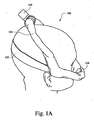
図1Aは、例示的な患者インターフェース108を装着している患者100を示す説明図である。この例において、患者インターフェース108は、患者の鼻とインターフェースしている(例えば、患者の鼻孔をシールし/封じ込める鼻マスクまたはインターフェース)。呼吸用気体の流れが、患者インターフェース108から患者の頬の上を通って患者の頭部まで伸張する導管104を介して患者に提供され得る。導管104は、本明細書に記載する形状変化材料から製造され得る。導管の全体または一部分のみが形状変化材料から形成されてもよい。患者インターフェース108を患者に固定することを可能にするためにストラップ102が設けられてもよい。導管104は、両頬の上に設けられ、使用中であるとき(例えば、処置の間)患者の頭部に接していてもよい。患者の頭部の各側面からの導管104は、コネクタ109に接続されてもよく、コネクタはその後、フロージェネレータに接続するチューブに取り付けられる。
FIG. 1A is an illustration showing a
患者の頭部は一般的にサイズが異なる。頭部サイズが異なることに対処するための一般的な技法は、ストラップ102を緩めるかもしくは締めること、または、頭部サイズが異なる患者に異なる長さの導管104を提供することを含み得る。図1Aにおいて、導管は第1の最小サイズにおいて製造されてもよい。この例において、最小サイズの導管が患者100の頭部に適合し得る。
The patient's head is typically different in size. Common techniques for dealing with different head sizes may include loosening or tightening
図1Bは、図1Aの例示的な患者インターフェース108を装着している別の患者110を示す説明図である。この図において、患者110の頭部サイズは患者100の頭部サイズよりも大きい。さらに、マスクおよび関連付けられるヘッドギア(例えば、ストラップ102)ならびに導管104は同じ導管(または同じモデル)であってもよい。しかしながら、図1Bにおいて、導管104は電荷106を介して電気的に刺激され得る。この電荷によって、導管の長さが増大して、形状変化材料のサイズが変化することに起因してより大きい頭部サイズに適応することができる。このように、導管は、患者100の第1の頭部サイズに適合する第1のサイズにおいて供給され得る。特定の例の実施形態において、この第1のサイズは、最小頭部サイズに適合するサイズであってもよい。しかしながら、供給される導管のサイズは第1のサイズから第2のサイズ(例えば、患者110)まで調整されてもよい。加えて、サイズは第1のサイズと第2のサイズとの間で(例えば、中間または第3のサイズに)調整されてもよい。
FIG. 1B is an illustration showing another
特定の事例において、患者インターフェースは、患者インターフェースを患者の頭部または顔に固定するためのストラップまたは他のタイプのヘッドギアを含んでもよい。ストラップを締めることによって、より良好なまたはより有効なシールを形成することができる。例えば、図1Aにおけるストラップ102は、患者インターフェース108を患者の鼻に保持してより有効なシールを形成するように作用することができる。このように、電荷が印加されてストラップがよりきつく締められ得るように、ストラップ102は形状変化材料から形成され得る。代替的に、ストラップが所定位置に配置される前にストラップに電荷が印加されてもよい。これによって、ヘッドギアを患者に対してより容易に配置することが可能になり得る。したがって、患者インターフェース、導管、ストラップなどが適切に配置されると、印加される電荷は低減または完全にオフになってもよい。このとき、電荷の低減の結果として、ストラップの全体的なサイズが低減し得、患者インターフェースが患者の顔に固定されることが可能になる。
In certain instances, the patient interface may include a strap or other type of headgear for securing the patient interface to the patient's head or face. By tightening the strap, a better or more effective seal can be formed. For example, the
特定の例の実施形態は、張力またはストラップにかかっている力をモニタリングするためのセンサを含んでもよい。これらの値に基づいて、インターフェースを介して患者に所定の力を与えるようにストラップ張力が調製されるように、電荷が自動的に制御され得る。特定の例の実施形態において、張力または力は、患者インターフェースが堅固であるが依然として快適である(例えば、きつすぎない)ことを示す値に関係する所定の力であってもよい。特定の例の実施形態において、ストラップ長が患者によって制御可能であってもよい。例えば、ダイヤルまたは他の制御部が呼吸補助システムとともに含まれてもよい(例えば、フロージェネレータ上に配置される)。特定の例の実施形態において、ストラップは患者が取り外すことを可能にするために(例えば、より多くの電荷を印加することによって)サイズを増大されてもよい。特定の例において、ストラップによって加えられた現在の力を超える力を患者が与えるときに、追加の電荷がトリガされてもよい。これは、センサによって検知されて、追加の電荷がトリガされてもよい。 Certain example embodiments may include a sensor for monitoring tension or force on the strap. Based on these values, the charge can be automatically controlled so that the strap tension is adjusted to provide a predetermined force to the patient via the interface. In certain example embodiments, the tension or force may be a predetermined force related value that indicates that the patient interface is robust but still comfortable (eg, not too tight). In certain example embodiments, the strap length may be controllable by the patient. For example, a dial or other control may be included with the respiratory assistance system (eg, located on the flow generator). In certain example embodiments, the straps may be increased in size (eg, by applying more charge) to allow the patient to remove. In certain instances, additional charge may be triggered when the patient applies a force that exceeds the current force applied by the strap. This may be detected by a sensor to trigger an additional charge.
特定の例の実施形態において、ストラップのきつさは患者の呼吸パターンまたは睡眠状態に基づいて調整されてもよい。例えば、ストラップは患者が起きている間は相対的に緩くてもよい。一方、患者が眠りにつくと、ストラップは患者インターフェースに対するより良好なシールを確保するために締められてもよい。 In certain example embodiments, strap tightness may be adjusted based on the patient's breathing pattern or sleep state. For example, the strap may be relatively loose while the patient is awake. On the other hand, when the patient falls asleep, the strap may be tightened to ensure a better seal to the patient interface.
特定の例の実施形態において、患者インターフェースのストラップは、患者が息を吐いている間は緩められてもよい。例えば、ストラップ長が増大してもよく、またはストラップの幅が低減してもよい。これによって、患者インターフェースからの(例えば、CO2などの)排気が可能になり得る。特定の例の実施形態において、ストラップは、患者が息を吸っている間は締められて、患者インターフェース漏れの機会が低減されてもよい。 In certain example embodiments, the patient interface strap may be loosened while the patient exhales. For example, the strap length may be increased or the strap width may be decreased. This may allow exhaust (eg, CO 2 ) from the patient interface. In certain example embodiments, the strap may be tightened while the patient is inhaling to reduce the chance of patient interface leakage.
図1Cは、例示的なストラップまたは締め具を示す説明図である。ストラップ120は第1の形状124において提供されてもよい。これは、サイズ調整材料から形成されたストラップ120の非帯電形状であってもよい。ストラップ120に電荷126が印加されると、ストラップ120は形状124から形状122へと変化し得る。したがって、ストラップのサイズまたは高さは印加される電荷に基づいて調整され得る。
FIG. 1C is an illustration showing an exemplary strap or fastener. The
図1D−1は、第1の非帯電ベースの形状130を有するストラップ134の例示的な断面図であり、電荷136がストラップ134に印加されると、これは第2の形状132に変化する。特定の例の実施形態において、ストラップは、1つの寸法(例えば、厚さ)、2つの寸法(例えば、幅および厚さ)、および/または3つの寸法が増大してもよい。例えば、ストラップの深さのみが調製されて、一方で長さおよび/または幅は変更されないように、電荷が印加されてもよい。
FIG. 1D-1 is an exemplary cross-sectional view of a
図1D−2は、特定の例の実施形態によるストラップまたは締め具の別の例示的な断面図である。ストラップは、電気活性ポリマー層135および1つまたは複数の電極層133を含む誘電体ポリマー131を含んでもよい。特定の例の実施形態において、電極層(例えば、2つ以上)は、中心ポリマー層のいずれの側面にも位置付けられてもよい。特定の例の実施形態において、電極層133は、中心ポリマー層135を完全にまたは部分的に覆う。
FIG. 1D-2 is another exemplary cross-sectional view of a strap or fastener according to certain example embodiments. The strap may include a
電源137が電極層に動作可能に接続されて、誘電体ポリマー131’に励起することまたは励起を停止することによって誘電体ポリマーの形状またはサイズを変化させるために電圧139を供給してもよい。この実施形態、および本明細書に記載する他の実施形態において、提供される電荷(例えば、電圧または電流)のレベルは、コントローラによって制御され、少なくとも2つの異なる技法によって印加されてもよいことが留意され得る。電圧または電流は、ポリマー部分135の形状および/またはサイズを実質的に段階的に変化させるように段階的に印加されてもよい。これは、決定されるまたは所定の電圧または電流変化の単一の段階、または、複数のより細かい段階を含んでもよい。代替的に、電圧または電流は、連続的に変化するように増大(または低減)されてもよく、したがってポリマーの形状および/またはサイズに漸進的な変化を付与する。これら2つの方法の間の組合せも適用されてもよい。
A
図1Eおよび図1Fは、電気的に刺激される導管を有する例示的な患者インターフェースを示す説明図である。ここで、眠っている患者140が、眠りながら患者インターフェース141を使用している。患者インターフェース141は、患者インターフェースに接続し、そして患者の頭部の上を通って点142まで伸張する2つの導管144および146を有する。導管に呼吸用空気を提供するホースまたはチューブ143が、頂点142において2つの導管(続いて患者)に接続する。導管144および146は、いずれかの導管、両方の導管が帯電することができるように、またはいずれの導管も帯電することができないように構築され得る。
1E and 1F are illustrations showing an exemplary patient interface having an electrically stimulated conduit. Here, the sleeping
患者によっては、横向きに寝る者もあり得る。特定の事例において、これによって導管のうちの一方において呼吸用気体の流れが制限される場合がある。例えば、図1Eおよび図1Fにおいて、導管144は、気体がほとんどまたはまったくホース143から導管144を通って患者インターフェース141へと通過することができないように圧迫される。この導管144が抑圧され得るため、患者への呼吸用空気の供給を確保するために、電荷148が導管146に印加され得る。そのような電荷は、導管の直径を増大させてより多くの空気が流れることを可能にすることができる。特定の例の実施形態において、電荷は、(例えば、わずかな捩れを取り除くことによって)効率を増大させるように作用することができる。特定の例の実施形態において、電荷は、導管144が抑圧されている間に、導管146がつぶれるかまたは流れが遅らせられるのを防止する一助となるように作用することができる。このように、導管144を通る空気流は一定程度まで妨げられるかまたは抑圧され得るが、導管146に印加される電荷148が、空気流が連続して眠っている患者に提供されることを確実にする一助となり得る。
Some patients sleep sideways. In certain cases, this may limit the flow of breathing gas in one of the conduits. For example, in FIGS. 1E and 1F, the
特定の例の実施形態において、すでにつぶれている導管の空気流容量の少なくとも一部分(またはすべて)を復元するために、つぶれた導管(例えば、144)に電荷が印加されてもよい。 In certain example embodiments, a charge may be applied to the collapsed conduit (eg, 144) to restore at least a portion (or all) of the airflow capacity of the already collapsed conduit.
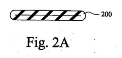
図2Aおよび図2Bは、特定の例示的な実施形態による導管を示す例示的な断面図である。特定の事例において、患者は、区別された邪魔にならない保管場所に管類、導管などを保管することを望む場合がある。しかしながら、完全に拡張したチューブを保管することは、チューブの全体の外周およびチューブが相対的に剛性であることの両方に起因して問題である場合がある。このように、特定の例の実施形態において、第1の小さいデフォルトのサイズにおいて管類200が提供され得る。このつぶれた構成において、チューブは相対的に平坦であり、それゆえ、開いた(動作可能な)構成のチューブと比較して、相対的に容易な保管オプションを提供することができる。保管場所から取り出され、空気流送出システムの一部分として使用されるとき、電荷204がチューブに印加され得、それによって、空気流路202が形成される。このように、一般的に大きく、かつ/またはかさばる場合があるチューブが、サイズ調整材料から構築され得る。チューブは、相対的に小さく保管しやすい第1のデフォルトのサイズで提供/出荷/販売されてもよい。しかしながら、チューブが空気流送出システムに加えられると、電荷がチューブに印加され得、それによって、チューブは開いた構成になって呼吸用気体が流れることが可能になる。
2A and 2B are exemplary cross-sectional views illustrating conduits according to certain exemplary embodiments. In certain instances, a patient may desire to store tubing, conduits, etc. in a separate, unobstructed storage location. However, storing a fully expanded tube can be problematic due to both the overall circumference of the tube and the relative rigidity of the tube. Thus, in certain example embodiments,
特定のコンポーネントのサイズを調整または低減することによって、移動のための保管をより容易にすることも可能になり得る。例えば、導管、管類、ストラップなどのサイズを低減することによって、ユーザが飛行機によって移動しているときにコンポーネントをより容易に荷詰めすることが可能になり得る。 By adjusting or reducing the size of certain components, it may also be possible to make storage for movement easier. For example, reducing the size of conduits, tubing, straps, etc. may allow components to be more easily packed when the user is traveling by plane.
特定の例の実施形態は、平坦な初期位置において提供されるストラップまたは他のヘッドギアをも含んでもよい。平坦な(または容易に保管可能な)コンポーネントは、その後、サイズまたは形状を増大させるために電荷を印加され得る。例えば、相対的に2次元形状のコンポーネント(例えば、図2Aのチューブ200)は、より3次元的な形状の増大したサイズに変化され得る。
Certain example embodiments may also include a strap or other headgear provided in a flat initial position. Flat (or easily storable) components can then be charged to increase size or shape. For example, a relatively two-dimensionally shaped component (eg,
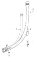
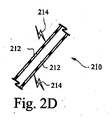
図2Cおよび図2Dは、例示的な導管を示す例示的な断面図である。導管210は、形状変化材料212から構築され得る。動作中、チューブは図2Cに示すようにもつれ、または捩れる場合がある。これによって、チューブ210を通る空気流が低減し得る。したがって、電荷214がチューブ210に印加され得る。電荷は、形状変化材料212を強化して、チューブ210を強制的により直線的な形状にして、導管を通る空気流をより良好に促進するように機能し得る。特定の例の実施形態において、電荷の量は、導管が屈曲または湾曲することができるように、導管の複数の区画の間で変化または分割されてもよい。
2C and 2D are exemplary cross-sectional views illustrating exemplary conduits. The
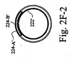
図2E−1〜図2E−3は、例示的な導管の斜視図および2つの断面図を示す。らせん状に形成された電気活性ポリマーストリップ224が、導管220の可撓性管状本体を形成する膜222に付着され得る。特定の例の実施形態において、ポリマー部分は、縦方向に成形された本体(例えば、図2E−1に示すような)の外部に配置されたらせん形状電気活性ポリマーストリップの形態にある。特定の例の実施形態において、電気活性ポリマーストリップは、膜の内部に配置される。特定の例の実施形態において、1つまたは複数の電気活性ポリマーストリップが、膜の内部および外部に配置される。図2E−3に示すように、電気活性ポリマーストリップは、電極または誘電体層224−Aの間に挟まれ、封入され、または配置されたポリマー224−Bを含んでもよい。
2E-1 to 2E-3 show a perspective view and two cross-sectional views of an exemplary conduit. A spirally formed
図2F−1〜図2F−3は、刺激を受けているときの、図2E−1〜図2E−3に示す例示的な導管の斜視図および2つの断面図を示す。励起状態において、電極層224−A’に電圧が印加され、それによって、ポリマー層224−B’の形状が調製される。このように、導管220’は半径および/または軸方向に(例えば、直径および/または長さが)拡張される。 2F-1 to 2F-3 show a perspective view and two cross-sectional views of the exemplary conduit shown in FIGS. 2E-1 to 2E-3 when under stimulation. In the excited state, a voltage is applied to the electrode layer 224-A ', thereby adjusting the shape of the polymer layer 224-B'. In this way, the conduit 220 'expands radially and / or axially (eg, diameter and / or length).
電圧または電流は、導管220の状態をつぶれた状態から開いた状態へと、実質的に段階的に変化させるように段階的に印加されてもよい。これは、提供される電圧または電流の単一の段階、または、複数のより細かい段階を含んでもよい。代替的に、電圧または電流は、実質的に連続的に変化するように増大(または低減)されてもよく、したがって電気活性ポリマーストリップ224の形状および/またはサイズに漸進的な変化を付与し、導管220の状態をつぶれた状態から開いた状態へと徐々に変化させる。
The voltage or current may be applied stepwise to substantially change the state of the
図2G−1および図2G−2は、別の例示的な導管の斜視図および断面図を示す。ここで、導管240は、導管240の本体を形成する膜242の本体に沿って対として形成される電気活性ポリマーストリップ244を含む。電気活性ポリマーストリップ244の種々のタイプの分布が、様々な例の実施形態にしたがって実装されてもよい。例えば、電気活性ポリマーストリップは、本体に沿った交互の側面にずらして配置されてもよい。図2G−1に示す例において、電気活性ポリマーストリップは対になって分散されており、ここで、1つまたは複数の対は、本体の対向する側面に配置された2つのストリップを含む。
2G-1 and 2G-2 show perspective and cross-sectional views of another exemplary conduit. Here, the
図2G−2には、導管240’の励起構成が示されている。電気活性ポリマーストリップ244’に電圧が供給されており、この電圧によって電気活性ポリマーストリップは拡張し、それによって、膜242’および導管240’が伸張している。特定の例の実施形態において、軸方向における(例えば、導管の長さに沿った)膨張をもたらすために、縦方向電気活性ポリマーストリップが膜の長さに沿って設けられてもよい。 In FIG. 2G-2, the excitation configuration of conduit 240 'is shown. A voltage is applied to the electroactive polymer strip 244 ', which expands the electroactive polymer strip, thereby stretching the membrane 242' and the conduit 240 '. In certain example embodiments, longitudinal electroactive polymer strips may be provided along the length of the membrane to provide expansion in the axial direction (eg, along the length of the conduit).
図3は、検出された力に応じて電荷を印加するための例示的なプロセスを示すフローチャートである。印加された電荷は、例示的な呼吸補助コンポーネントの形状を変化させるように作用してもよい。特定の例の実施形態において、チューブが第1の「弛緩した」位置(例えば、電荷が印加されていない)に設けられてもよい。過剰な力またはチューブの引きずりが発生するときを検出するためにセンサが実装されてもよい。例えば、チューブはもつれる場合がある。チューブに加えられる力の増大が検知されると(ステップ300)、電荷が活性化されて(ステップ302)、チューブが電気的に刺激され、チューブのサイズ(例えば、長さのみ)が増大させられて、患者に固定された患者インターフェースが不安定になるのを(例えば、マスクをずらしてマスクをずれた位置に引っ張るチューブの引きずりを)防止する一助になり得る。 FIG. 3 is a flowchart illustrating an exemplary process for applying a charge in response to a detected force. The applied charge may act to change the shape of the exemplary respiratory assistance component. In certain example embodiments, the tube may be provided in a first “relaxed” position (eg, no charge is applied). A sensor may be implemented to detect when excessive force or tube drag occurs. For example, the tube may be tangled. When an increase in force applied to the tube is detected (step 300), the charge is activated (step 302), the tube is electrically stimulated, and the tube size (eg, length only) is increased. Thus, it may help to prevent the patient interface secured to the patient from becoming unstable (eg, dragging the tube that displaces the mask and pulls the mask to a displaced position).
通気部/AAV
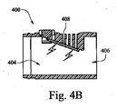
図4Aおよび図4Bは、特定の例示的な実施形態による例示的な窒息防止通気部を示す例示的な断面図である。特定の事例において、窒息防止通気部400が、患者インターフェース上に、またはそれとともに設けられてもよい。第1の動作モードを図4Bに示す。ここで、フラップ408は1つまたは複数の開口402に対して、開口を閉じるように運動可能である。したがって、気体が404から(フロージェネレータから)406へ(患者の口または鼻へ向かって)流れることができる。フラップ408は、電荷を介して1つまたは複数の開口に対して運動可能であり得、それによって、これは第1の位置に向かって付勢されて、1つまたは複数の開口402を閉鎖する。
Ventilation part / AAV
4A and 4B are exemplary cross-sectional views illustrating an exemplary anti-suffocation vent according to certain exemplary embodiments. In certain instances, a
フラップ408は、図4Aに示す第2の位置に変化することもできる。例えば、フロージェネレータが故障した場合、フラップ408に対する電荷が停止され得る(例えば、電力がもはや提供されていないため)。この位置において、1つまたは複数の開口402は開いており、患者側端部406から1つまたは複数の開口402を通じて外側大気へ、およびその逆に空気が流れることを可能にし得る。したがって、フラップ408は窒息防止弁(AAV)として機能することができる。
The
図4Cは、特定の例の実施形態による(例えば、図4Aおよび図4Bに示す窒息防止通気部によって実行されてもよい)フラップの断面図を示す。図4Cに示す例示的なフラップ420は、誘電活性ポリマーによって実装されてもよい。フラップ420は、電極422Aおよび422Bを含み、その間にポリマー層426が配置される。電極は、例えば、グラファイト膜に基づく材料のような、任意のタイプの可撓性導電性材料であってもよいことは諒解されよう。この例において、1つまたは複数の次元においてポリマーの膨張を制限するために、抑制層がポリマー(例えば、電極および/またはポリマー)に配置される。抑制層は、ポリマーの形状が変形している間、概してその形状が変化しない材料(例えば、非伸縮可能織物材料のような、可撓性であるが、伸張可能ではない任意の材料)を含んでもよい。図4Cにおいて、ポリマーの長さ(例えば、高さ)寸法を抑制するために抑制層424が配置されている。結果として、電極422A’および422B’に電圧が印加されると、ポリマー426’は膨張しようとするが、その膨張は抑制層424’によって制限される。したがって、フラップ420’は、抑制層の側である抑制されている側において捻じれ、それによって、湾曲するかまたは位置が変化する。フラップが直線構成から湾曲構成へと変化することによって、フラップが新たな位置へと効率的に移動することができる。
FIG. 4C shows a cross-sectional view of a flap according to certain example embodiments (eg, may be performed by the anti-suffocation vent shown in FIGS. 4A and 4B). The
図5は、検出された圧力に応じて電荷を印加するための例示的なプロセスを示すフローチャートである。電荷は、例示的な呼吸補助コンポーネントの形状を変化させることができる。特定の例の実施形態において、フラップは、定流フラップとして機能してもよい。フラップに提供される電荷は、フロージェネレータによって制御され得る。電荷の量は、マスクに供給されたまたはマスクにおいて検出された圧力に比例し得る(ステップ500)。言い換えれば、定流弁のように、弁はより多くの電荷を印加することによってより高い圧力において通気孔を閉じることができる(ステップ502)。特定の例の実施形態において、そのような技法は、2段階CPAP両方によって適用されてもよい。 FIG. 5 is a flowchart illustrating an exemplary process for applying charge in response to detected pressure. The charge can change the shape of the exemplary respiratory assist component. In certain example embodiments, the flap may function as a constant flow flap. The charge provided to the flap can be controlled by the flow generator. The amount of charge may be proportional to the pressure supplied to the mask or detected at the mask (step 500). In other words, like a constant flow valve, the valve can close the vent at higher pressure by applying more charge (step 502). In certain example embodiments, such techniques may be applied by both two-stage CPAP.
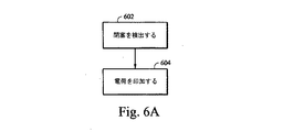
特定の例の実施形態は、通気部内の遮断を是正するように作用することができる。図6Aは、検出された閉塞に応じて電荷を印加するための例示的なプロセスのフローチャートである。電荷は、例示的な呼吸補助コンポーネントの形状を変化させることができる。例えば、センサまたは他のデバイスを使用して、通気部が遮断されているか否かをモニタリングまたは判定することができる(ステップ602)。通気部におけるまたはその中の遮断物が検出されると、形状変化材料から構築された通気部に電荷が印加され得る(ステップ604)。電荷の結果として、通気部は、形状を変化させ、通気部を遮断している1つまたは複数の異物を(例えば、通気孔を広くすることによって)吐出することができる。例えば、湿気を含んだ空気の結果として水が蓄積される結果として、チューブまたは患者インターフェースの通気孔が完全にまたは部分的に遮断されることになり得る。特定の例の実施形態において、孔のサイズを低減して通路から水(または他の遮断物)を除去するのを可能にしてもよい。具体的には、孔のサイズを低減することによって、孔または通路内の物体が、孔の直径が低減することによって強制的に排出され得る。 Certain example embodiments may act to correct a blockage in the vent. FIG. 6A is a flowchart of an exemplary process for applying a charge in response to a detected occlusion. The charge can change the shape of the exemplary respiratory assist component. For example, a sensor or other device can be used to monitor or determine whether the vent is blocked (step 602). If an obstruction at or in the vent is detected, a charge may be applied to the vent constructed from the shape-changing material (step 604). As a result of the charge, the vent can change shape and eject one or more foreign objects that block the vent (eg, by widening the vent). For example, the accumulation of water as a result of moist air can result in complete or partial blockage of the tube or patient interface vents. In certain example embodiments, the pore size may be reduced to allow removal of water (or other blockage) from the passage. Specifically, by reducing the size of the holes, objects in the holes or passages can be forced out by reducing the diameter of the holes.
図6B−1および図6B−2は、例示的な通気コンポーネントを示す例示的な断面図である。通気部610は、1つまたは複数の孔614を含むことができる。通気部は、形状変化材料612から形成されてもよい。第1の動作モードにおいて、電荷616が形状変化材料612に印加され得る。電荷616によって、材料が膨張し、孔614を閉じるかまたは収縮させることができる(またはその逆)。電荷616は低減するかまたはなくすことができる。そのような状況において、通気部610を含む形状変化材料612が収縮すると、孔614はサイズが増大し得る。孔614のサイズが増大することによって、遮断している物体がより大きい通気孔を通じてより容易に移動することができるため、通気部から閉塞物を除去することが容易になり得る。特定の例の実施形態において、孔サイズの変化は、形状変化材料612に対する種々のレベルの電荷によって制御することができる。
6B-1 and 6B-2 are exemplary cross-sectional views illustrating exemplary ventilation components. The
特定の例の実施形態において、通気部は、通気部が遮断されていると検出された場合には、通気部に電荷が送られ得るように動作され得る。結果もたらされる通気部の形状の変化は、通気部を遮断している異物(例えば、マスク内部の湿気を含んだ空気からの水)を排出するように作用し得る。 In certain example embodiments, the vent may be operated such that charge can be delivered to the vent if it is detected that the vent is blocked. The resulting change in shape of the vent can act to expel foreign matter (eg, water from the humid air inside the mask) blocking the vent.
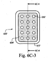
図6C−1および図6C−2は、それぞれ、例示的な通気コンポーネントの例示的な上面図および断面図である。図6C−1は、電極654の間に配置された誘電体ポリマー層652を含む、非励起状態の例示的な通気部650を示す。通気部は、通気開口656を含む。通気部650’が励起されると、誘電体ポリマー652’が膨張する。結果として、図6C−3および図6C−4に示す励起状態のポリマー内の開口656’は、直径が低減しており、空気流の低減をもたらす。
6C-1 and 6C-2 are exemplary top and cross-sectional views, respectively, of an exemplary ventilation component. FIG. 6C-1 illustrates an
前頭部支持
図7Aおよび図7Bは、調整可能な例示的な前頭部支持コンポーネントを有する例示的な患者インターフェースを示す説明図である。患者インターフェース702が患者700に提供される。患者700の前頭部とインターフェースするための前頭部支持パッド704が構築され得る。患者の頭部との関係における前頭部支持パッド704の位置は、前頭部支持パッド704に電荷706を印加することによって調整することができる。印加される電荷によって、前頭部支持パッド704は、図7Bに示すようにより大きくなることができる。サイズが増大することによって、前頭部支持パッドは患者700の頭部(例えば、前頭部)と接触することができる。リビングヒンジのようなヒンジが708に設けられて、前頭部支持パッド704の患者700の頭部に対する回転運動を可能にすることができる。
Forehead Support FIGS. 7A and 7B are illustrations showing an exemplary patient interface with an exemplary adjustable forehead support component. A
患者がマスクの処置を終えると(例えば、目覚めた後)、患者インターフェース702を患者の頭部から取り外すことを容易にするために、患者によって電荷706をオフにすることができる。言い換えれば、前頭部支持パッド704に印加された電荷を除去することによって、前頭部支持パッド704は収縮することができ、もはや患者の前頭部と接しない。特定の例の実施形態において、前頭部支持パッドは1つのパッドであってもよい。しかしながら、他の例の実施形態において、前頭部支持パッドは2つ以上のパッドであってもよい。
Once the patient is done with the mask (eg, after waking up), the patient can turn off the
クッション
患者インターフェースのクッションコンポーネントも、形状変化材料から形成され得る。図8Aおよび図8Bは、特定の例の実施形態による患者インターフェースの例示的なクッションコンポーネントの例示的な断面図である。図8Cは、患者インターフェースの例示的なクッションをモニタリングおよび/または調整するための例示的なプロセスを示すフローチャートである。特定の例の実施形態において、クッションはいくつかの区画(802A、802B、802C、および802D)に分割され得る。各々の区画は、その領域内でクッションに加えられる圧力をアクティブにモニタリングすることができる。例えば、圧力センサまたはトランスデューサが、1つまたは複数の区画内に設けられてもよい。特定の例の実施形態について、マイクロホンが利用されてもよい。いずれにせよ、検出ユニットを使用して、クッションの1つまたは複数の区画をモニタリングすることができる(ステップ810)。クッション内の漏れが、図8B内の802Bのような特定の領域内で検出されると、その特定の領域に電荷が印加され得る(ステップ812)。結果もたらされる電荷は、クッションのサイズを増大させ、クッションによって形成されるシールの有効性を(例えば、漏れを閉じることによって)増大させるように作用することができる。
Cushion The cushion component of the patient interface can also be formed from a shape-changing material. 8A and 8B are exemplary cross-sectional views of exemplary cushion components of a patient interface according to certain example embodiments. FIG. 8C is a flowchart illustrating an exemplary process for monitoring and / or adjusting an exemplary cushion of a patient interface. In certain example embodiments, the cushion may be divided into several compartments (802A, 802B, 802C, and 802D). Each compartment can actively monitor the pressure applied to the cushion within that area. For example, a pressure sensor or transducer may be provided in one or more compartments. For certain example embodiments, a microphone may be utilized. In any case, the detection unit can be used to monitor one or more compartments of the cushion (step 810). If a leak in the cushion is detected in a particular area, such as 802B in FIG. 8B, charge may be applied to that particular area (step 812). The resulting charge can act to increase the size of the cushion and increase the effectiveness of the seal formed by the cushion (eg, by closing the leak).
図8Dは、特定の例の実施形態にしたがって調整された患者インターフェースの例示的なクッションコンポーネントの例示的な断面図を示す。ここで、クッション820は、クッション820が電荷をクッション領域822A、822B、822C、および822Dにわたってパルスまたは分散されることができるように設定され得る。したがって、患者の顔にはたらく力の量を、複数のクッション領域に対する電荷の印加を回転させることによって定期的に調整することができる。例えば、クッションは口領域においてパルス824によって開始し得、その後、右頬領域822Dにパルス826が印加され得る。このタイプの設定は、患者の顔の領域を休ませるように機能することができ、それによって、長時間の使用についてマスクをより快適にする。
FIG. 8D illustrates an example cross-sectional view of an example cushion component of a patient interface adjusted in accordance with certain example embodiments. Here, the
図8Eは、患者インターフェースの例示的なクッションを調整する例示的なプロセスを示すフローチャートである。ステップ830において、特定の領域に電荷が印加される。ステップ832における所定の期間の後、新たな領域(または複数の領域)がステップ834において選択され、電荷を印加するプロセスが選択された領域に対して新たに行われる。特定の例の実施形態において、選択される領域は所定のパターンに基づいてもよい。特定の例の実施形態において、選択される領域は、何らかの追加の判定(例えば、図8Cに関連して上述したようなもの)に基づいて選択されてもよい。特定の例の実施形態において、選択される領域は、1つまたは複数の領域の間からランダムに選定され、したがって1つまたは複数の部分領域が形成されてもよい。特定の例の実施形態において、2つ以上のパルスが時間的に重なるように印加されてもよい。例えば、クッション領域822Bおよび822Dは両方とも、同時に1つの電荷を印加されてもよい。
FIG. 8E is a flowchart illustrating an exemplary process for adjusting an exemplary cushion of a patient interface. In
特定の例の実施形態において、この循環する動作がどのように行われるかを制御するために、ユーザまたは自動制御ユニット(例えば、プロセッサまたは他のタイプの回路を含む)によって追加の基準が供給されてもよい。例えば、ユーザがこのサイクルがどれだけ迅速に行われるかを設定してもよい。特定の例の実施形態において、ユーザはサイクルのパターンを設定してもよい。例えば、822A→822C→822D→822B→822Aとしてもよい。特定の例の実施形態において、電荷が所与の領域に印加される時間は、すべての領域について同じであってもよく、または、領域間で変化してもよい。特定の例の実施形態において、センサおよび/または処理システムが、少なくとも1つのユーザ構成可能変数に基づき得る所定の基準(または基準のセット)に基づいて電荷の循環をモニタリングし、サイクルを調整し得る。例えば、サイクルは一定の時間量の後に減速してもよい。サイクル速度は線形的にまたは別の形状に(例えば、指数関数的に)調整されてもよい。一例において、サイクル速度は、患者が眠っていると判定されるときに調整されてもよい。この判定に基づいて、速度は、増大、低減、または同じままとすることができる。特定の例の実施形態において、循環プロセスは、ユーザの顔をマッサージするようにも動作し得る。特定の患者について、これは、睡眠の質、および、ユーザが眠りにつく能力を増大させる一助となり得る。
In certain example embodiments, additional criteria are provided by a user or automatic control unit (eg, including a processor or other type of circuitry) to control how this cyclical action is performed. May be. For example, the user may set how quickly this cycle occurs. In certain example embodiments, the user may set a cycle pattern. For example,
特定の事例において、患者に対する呼吸補助を促進するために適切なシールが実施され得る。しかしながら、マスクを顔または患者の顔の一部分の上にシールすることによって、一定量の圧力が顔に加えられることが必要になり得る。患者は一般的に数時間にわたって(例えば、眠っている間)マスクまたは他の患者インターフェースを装着するため、この一定の圧力は患者の顔(例えば、顔面筋)にとって疲労をもたらすものであり得る。 In certain cases, an appropriate seal can be implemented to facilitate respiratory assistance to the patient. However, it may be necessary to apply a certain amount of pressure to the face by sealing the mask over the face or part of the patient's face. Because the patient typically wears a mask or other patient interface for several hours (eg, while sleeping), this constant pressure can cause fatigue on the patient's face (eg, facial muscles).
図8F−1および図8F−2は、患者の呼吸に基づいて調整された例示的なクッションを有する例示的な患者インターフェースの例示的な断面図である。患者インターフェース842は、患者840の鼻および/または口を覆うためのシールを提供し得る。シールは、電荷848を、患者インターフェースの一部分である形状変化材料846に印加することによって実施またはサポートされ得る。例えば、電荷は、クッション846.2および/またはクッション側壁846.3の下でシーリング膜846.1に印加され得る。この電荷によって、シールの有効性が様々な度合いまで)増大し得る。この例において、患者がフロージェネレータまたは他の空気流デバイスに接続されたチューブ845を通じて吸入844しているとき、電荷848がシール(例えば、クッション846)に印加され得る。
8F-1 and 8F-2 are exemplary cross-sectional views of an exemplary patient interface having an exemplary cushion adjusted based on patient breathing.
図8F−2において、患者840は、チャンバ852を通じて、および通気孔850を通じて提供される空気流路854を介して息を吐いている。患者が息を吐くとき、図8F−1に示す電荷848はオフになり(または低減され)得、それによって、クッション846はもはや顔に接しないか、またはより低い力で顔に接する。患者の顔に加えられる力が低減することによって、顔(例えば、顔面筋)が呼気の間に「休む」ことが可能になり得る。
In FIG. 8F-2,
図8F−3は、呼吸補助コンポーネントの調整を決定するための特定の例の実施形態にしたがって使用され得る例示的なグラフを示す。電荷を患者インターフェースにいつ印加すべきかの決定は、患者の呼吸プロセスの間にモニタリングされる圧力および/または流れの特性に基づき得る。グラフ854は、圧力対時間のグラフを示している。特定の例の実施形態において、そのようなグラフを分析することが、いつ電荷が印加されるべきか、および、電荷が低減またはオフにされ得るときを決定する一助となり得る。したがって、点856において、患者が息を吸っているときに電荷が印加され得る。患者が息を吐くときの点858までグラフが進むと、電荷は低減または除去され得る。電荷の除去によって、患者が息を吐くことができるゆとりが増大し得る。特定の事例において、電荷の除去によって、患者の顔面筋が呼気の間に休むことが可能になり得る。特定の例の実施形態において、検出される圧力に対するある割合の電荷パーセンテージが実装され得る。例えば、圧力が増大すると(例えば、吸気)、印加される電荷がそれに対応して増大され得る。逆に、圧力が降下すると(例えば、呼気の間)、印加される電荷は圧力の降下に対応して(例えば、漸進的に)低減され得る。特定の例の実施形態について、他のパラメータがモニタリングされてもよい。例えば、マスクの一部分または患者を通る空気の流速が測定されてもよい。特定の例の実施形態において、圧力センサ、流量センサなどが、マスク、チューブ、または、患者に対する呼吸補助に使用される他のコンポーネント内に配置されてもよい。そのようなセンサからの読み値が使用されて、電荷が印加され得るとき、および、印加されるべき電荷のレベルを判定する一助となり得る。
FIG. 8F-3 illustrates an exemplary graph that may be used in accordance with certain example embodiments for determining adjustments to respiratory assistance components. The determination of when a charge should be applied to the patient interface may be based on pressure and / or flow characteristics monitored during the patient's respiratory process.
特定の例の実施形態において、呼吸補助システムの他のコンポーネントが、検出される患者の呼気/吸気状態に基づいて調整されてもよい。例えば、呼気の間に通気孔850のサイズが増大されて、患者の呼気、CO2の排気などが容易になり得る。特定の例の実施形態において、患者インターフェースは、CPAP処置の一部分として使用されてもよい。そのような事例において、患者が息を吐こうと働きかける努力の程度は(例えば、気道陽圧のために)通常よりも大きくなり得る。したがって、圧力のいくらかは、(例えば、マスクを出るより大きな流れを提供するために)通気孔850のサイズを増大させることによって、患者による呼気の間に「排出」され得る。これによって、そうでない場合よりも、患者による呼気を容易にすることが可能になり得る。さらに、通気孔は、患者の吸気の間により良好なシールをもたらすことを可能にするために「通常」に戻り得る。
In certain example embodiments, other components of the breathing assistance system may be adjusted based on the patient's expired / inspiratory condition to be detected. For example, the size of the
図8G−1および図8G−2は、異なる顔特徴を有する2人の異なる患者に適合された例示的なクッションを有する例示的な患者インターフェースの例示的な断面図である。患者顔特徴は、人ごとに異なり得る。これらの異なる顔特徴は、時としてどのタイプのマスクまたはどのタイプのインターフェースをその患者に使用すべきかを決定する難しさを増大させる可能性がある。特定の例の実施形態において、形状変化材料を使用して、クッション、マスクなどの患者の顔への適合を可能にする(例えば、所与の患者の身体計測により良好に適合する)ことができる。ここで、患者862は相対的に平坦な鼻梁863を有し得る。対照的に、患者861はより高い鼻梁865を有し得る。患者インターフェース860は形状変化材料864を含み得、それによって、電荷868を印加することによって形状変化材料864を、シールの提供を可能にする位置に調整することができる。患者の身体計測に基づいて電荷の量を調整することができる。したがって、図8G−1において、患者862の鼻梁が相対的に平坦であることに起因して、形状変化材料864に電荷は印加されなくてもよい。一方、図8G−2において、(例えば、患者861の鼻梁が高いことに起因して)材料866が患者861の鼻梁領域とより良好に接するように、電荷868が印加され得る。
8G-1 and 8G-2 are exemplary cross-sectional views of an exemplary patient interface having an exemplary cushion adapted to two different patients having different facial features. Patient facial features can vary from person to person. These different facial features can sometimes increase the difficulty of determining what type of mask or interface should be used for the patient. In certain example embodiments, the shape-changing material can be used to allow adaptation to a patient's face, such as a cushion, mask, etc. (eg, better fit a given patient's anthropometry). . Here, the
特定の例の実施形態において、患者インターフェースは、クッション内に1つまたは複数のセンサを含んでもよい。センサは、クッションの患者の顔への適合を改善することを可能にするためにどの程度の電荷を患者の顔の所与の領域に印加すべきかを決定するように動作することができる。例えば、1つのセンサは、クッションが一般的に患者の鼻梁に接する位置においてクッション内/上に配置され得る。センサからの読み値に基づいて、クッションのその鼻梁領域に電荷を印加することができ、それによって、クッションは(例えば、図8F−1および図8F−2に示すように)患者の鼻梁に適切にインターフェースするように形状を変化させる。 In certain example embodiments, the patient interface may include one or more sensors within the cushion. The sensor is operable to determine how much charge should be applied to a given area of the patient's face to allow the cushion to improve the fit of the patient's face. For example, one sensor may be placed in / on the cushion at a location where the cushion generally contacts the patient's nasal bridge. Based on readings from the sensor, a charge can be applied to that nasal bridge region of the cushion so that the cushion is suitable for the patient's nasal bridge (eg, as shown in FIGS. 8F-1 and 8F-2). Change the shape to interface.
特定の例の実施形態において、所与の患者に対する適切な適合を達成するためにどの程度の電荷をクッションに印加すべきかの構成は、医療専門家の助けを借りて行われてもよい。例えば、患者が最初にマスクを取得するとき、シールの形成を可能にするためにどれだけ多くのまたはどれだけ少ない電荷を患者の顔の様々な領域に印加すべきかを決定する適合セッションが行われ得る。取得情報は記憶装置(例えば、不揮発性メモリ)内に記憶され得る。この記憶場所は、マスク、フロージェネレータ、または呼吸補助システムの他のコンポーネントに位置してもよい。特定の例の実施形態において、メモリはそのようなシステムと(例えば、ストレージ情報がUSBドライブ上に記憶されているユニバーサル・シリアル・バス・ポートを通じて)インターフェースすることができる。これによって、読み値の可搬性が可能になり得る。 In certain example embodiments, the configuration of how much charge should be applied to the cushion to achieve a proper fit for a given patient may be done with the help of a medical professional. For example, when a patient first acquires a mask, an adaptation session is performed to determine how much or how little charge should be applied to various areas of the patient's face to allow the formation of a seal. obtain. The acquired information can be stored in a storage device (eg, a non-volatile memory). This storage location may be located on the mask, flow generator, or other component of the respiratory assistance system. In certain example embodiments, the memory can interface with such a system (eg, through a universal serial bus port where storage information is stored on a USB drive). This may allow reading portability.
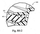
図8H−1および図8H−2は、患者インターフェースの例示的なフレームに組み込まれた例示的なクッションの例示的な断面図である。ここで、患者インターフェース870のクッション872は、フレームのチャネル876内に設けられ得る。クッション872は、フレーム内に緩やかに適合され得、それによって、クッションは、たとえクッションがチャネル876内に緊密にシールされていなくとも、フレームに固定されたままである。これによって、例えば、患者インターフェース870の患者の顔に対するより容易な初期配置が可能になり得る。図8H−2において、電荷874がクッション872の形状変化材料に印加される。この電荷874によって、クッション872がフレームチャネル内へと膨張し、それによって、クッションがフレームとシールし得る。特定の例の実施形態において、そのような電荷は処置セッションが開始するときに最初に印加されてもよい。例えば、患者がCPAP療法を受けている場合、電荷はフロージェネレータがオンになるときに開始されてもよい。
8H-1 and 8H-2 are exemplary cross-sectional views of exemplary cushions incorporated into an exemplary frame of a patient interface. Here, the
特定の例の実施形態において、電荷は、患者インターフェースに取り付けられたフロージェネレータがオンになるときに印加されてもよい。したがって、患者はクッションがチャネル内に緩やかに適合されている(例えば、電荷が印加されていない)ときに、患者インターフェースを所定位置に配置してもよい。患者インターフェースが適所に置かれると、患者はフロージェネレータをオンにすることができ、クッションに電荷が印加され得る。クッションは膨張して患者インターフェースのフレームとのシールを形成し得る。同様に、患者インターフェースによる処置を終えた後、電荷をオフにすることができ、クッションが収縮して患者インターフェースを患者の頭部からより容易に取り外すことが可能になる。 In certain example embodiments, the charge may be applied when a flow generator attached to the patient interface is turned on. Thus, the patient may place the patient interface in place when the cushion is gently fitted into the channel (eg, no charge is applied). Once the patient interface is in place, the patient can turn on the flow generator and a charge can be applied to the cushion. The cushion may expand to form a seal with the patient interface frame. Similarly, after finishing the treatment with the patient interface, the charge can be turned off and the cushion can contract to allow the patient interface to be more easily removed from the patient's head.
カフ
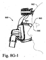
形状変化材料は、呼吸補助システムの他のコンポーネントに適用されてもよい。例えば、チューブは患者インターフェースをフロージェネレータに接続することができる。チューブ、またはチューブの一部分が、形状変化材料から形成されてもよい。図8I−1および図8I−2は、例示的な屈曲部と相互作用するチューブの例示的なカフを示す例示的な断面図である。フローシステム880の一部として、チューブのカフ部分882は、屈曲部分886に係合することができる。特定の例の実施形態において、屈曲部は、フロージェネレータと患者インターフェースとを接続するホースがもつれるのを防止する一助となるために、少なくとも1つの軸を中心として自由回転するために旋回するように取り付けられ得る。図8I−1において、カフ部分882は、非動作状態にあり得る(例えば、カフ部分は屈曲部分886より小さい場合がある)。この状態において、カフ部分882は、カフ部分882を屈曲部分886内へ挿入するのを容易にするためにより小さくなっていることができる。図8I−2において、電荷884が形状変化材料によってカフ部分882に印加される。電荷の印加によって、カフのサイズが増大して、屈曲部分886の側壁とより堅固にインターフェースする(例えば、カフを適所にロックする)ことができる。これによってシールが形成されて、屈曲部分886およびカフ部分882から/への空気流効率を増大することが可能になり得る。
The cuff shape change material may be applied to other components of the respiratory assistance system. For example, the tube can connect the patient interface to a flow generator. The tube, or a portion of the tube, may be formed from a shape changing material. 8I-1 and 8I-2 are exemplary cross-sectional views illustrating an exemplary cuff of a tube that interacts with an exemplary bend. As part of the
特定の例の実施形態において、カフ部分と屈曲部分との間のサイズ差は非常に小さいものであってもよく、それによって、カフの挿入に関係する摩擦力が依然として発生することができる。特定の例の実施形態において、カフ部分と屈曲部分との間のサイズ差はより大きいものであってもよく、それによって、それによってカフが挿入される摩擦力はほとんどまたはまったく加えられない。特定の例の実施形態において、電荷884は、フローシステム880のフロージェネレータがオンになるときにトリガされてもよい。
In certain example embodiments, the size difference between the cuff portion and the bent portion may be very small, so that frictional forces related to the insertion of the cuff can still be generated. In certain example embodiments, the size difference between the cuff portion and the bent portion may be larger, thereby applying little or no frictional force by which the cuff is inserted. In certain example embodiments, the
屈曲部
図9Aおよび図9Bは、特定の例示的な実施形態による屈曲部を示す説明図である。図9Cは、図9Bの例示的な断面図である。フローシステムの屈曲部900は回転可能とすることができる。例えば、屈曲部900のアーム部分902は位置903Aまたは903Bへと回転することができる。アーム部分902は、(例えば、フロージェネレータ上に位置する)インターフェース部分906に対して回転することができる。屈曲部、またはそのアーム部分のそのような回転は、特定の事例において、回転および/または位置の変化からチューブが引きずられる効果を増大する場合がある。したがって、特定の例の実施形態において、アーム部分および/またはインターフェース部分は、少なくとも部分的に、本明細書に記載する形状変化材料によって形成され得る。そのため、形状変化材料に印加される電荷904によって、電荷が印加される部分のサイズが増大し得る。このインターフェース部分906またはアーム部分902のサイズの増大は、これら2つの部分の間の摩擦抵抗を増大させるように作用し得る。特定の例の実施形態において、アーム部分902またはインターフェース部分906に対する電荷904の印加は、アーム部分902を特定の位置に「ロック」するように作用し得る。特定の例の実施形態について、これによってチューブの引きずりを低減することができる。特定の例の実施形態において、アーム部分902がロックされることによって、屈曲部のためのより安定したプラットフォームがもたらされ得る(例えば、それによってアームが常に自由に動くことがなくなる)。
Bent Part FIGS. 9A and 9B are illustrations showing a bent part according to certain exemplary embodiments. FIG. 9C is an exemplary cross-sectional view of FIG. 9B. The
睡眠マット
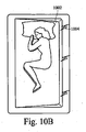
特定の患者にとって、横向きに寝るのが好ましい睡眠姿勢である場合がある。そのような姿勢は無呼吸事象を低減することもできる。図10Aおよび図10Bは、特定の例の実施形態による睡眠マット上の患者の説明図である。図10C〜図10Dは、図10Aおよび図10Bに示す例示的な睡眠マットの例示的な断面図である。睡眠マット1002は、形状変化材料から形成されてもよい。患者1000はセンサまたは他の判定システムによってモニタリングされ得る。システムは、患者が仰向けまたは正面向きに寝ている(例えば、図10Aに示すように)か否かをモニタリングし得る。この判定に基づいて、睡眠マット1002は電荷1004を印加され得る。この電荷は、睡眠マット1002の形状変化材料に作用して、特定の領域(図10Bの右側に示すように)において睡眠マット1002のサイズまたは形状を増大させることができる。このサイズの増大は、患者1000が眠りながら横向きになるのを容易にする(または、場合によってはさらに強制的にそうさせる)ように作用することができる。
Sleeping Mat Sleeping sideways may be the preferred sleeping posture for certain patients. Such posture can also reduce apneic events. 10A and 10B are illustrations of a patient on a sleep mat according to certain example embodiments. 10C-10D are exemplary cross-sectional views of the exemplary sleep mat shown in FIGS. 10A and 10B.
特定の例の実施形態において、睡眠マットは、患者が使用するシーツまたはマットレスであってもよい。特定の例の実施形態において、睡眠マットは、複数の異なる区画に分割されてもよい。例えば、睡眠マットは、左区画(例えば、患者1000の左)、中央区画、および右区画(例えば、図10Aにおける患者1000の右側)を有してもよい。異なる複数の区画は、患者が寝返りを打つのを補助するか、またはそうさせるように調整され得る。特定の例の実施形態において、患者が転がることになる方向は、患者が睡眠マット上で眠っている場所に基づいて変化してもよい。例えば、患者がベッドの左側で眠っている場合、システムは、患者が自分の左側に転がるのを補助するかまたはそうさせるために、右側(図10Bに示すような)とは反対に、睡眠マットの左側の高さを増大させることができる。
In certain example embodiments, the sleep mat may be a sheet or mattress used by the patient. In certain example embodiments, the sleep mat may be divided into a plurality of different compartments. For example, the sleep mat may have a left compartment (eg, the left of patient 1000), a center compartment, and a right compartment (eg, the right side of
特定の例の実施形態において、睡眠マット上で患者が眠っている場所を判定するために、1つまたは複数のセンサが睡眠マットの上または中に配置されてもよい。例えば、力センサが使用されてもよい。センサは、睡眠マット内の1つまたは複数の区画(例えば、すべての区画)をモニタリングしてもよい。 In certain example embodiments, one or more sensors may be placed on or in the sleep mat to determine where the patient is sleeping on the sleep mat. For example, a force sensor may be used. The sensor may monitor one or more compartments (eg, all compartments) in the sleep mat.
特定の例の実施形態において、患者が転がるのを容易にするために、睡眠マットの一方の側面が増大される代わりに低減されてもよい。例えば、マットはデフォルトのサイズにおいて供給されてもよい。睡眠マットのある位置に電荷を印加(または除去)することによって、その領域において睡眠マットのサイズ(例えば、厚さ)が低減し得る。特定の例の実施形態において、睡眠マットは、各々がサイズを増大および/または低減され得る複数の異なる部分に分割されてもよい。したがって、特定の例の実施形態において、睡眠マットは、睡眠マットの厚さが変化する結果として異なる断面が形成され得るように調整され得る。例えば、睡眠マットの1つまたは複数の部分に電荷を印加すること、および/または睡眠マットの1つまたは複数の部分から電荷を低減もしくは除去することによって、図10E、図10F、および図10Gに示すような断面が形成され得る。 In certain example embodiments, one side of the sleep mat may be reduced instead of being increased to facilitate the patient to roll. For example, the mat may be supplied in a default size. By applying (or removing) charge at a location on the sleeping mat, the size (eg, thickness) of the sleeping mat may be reduced in that region. In certain example embodiments, the sleep mat may be divided into a plurality of different portions, each of which may be increased and / or reduced in size. Thus, in certain example embodiments, the sleep mat may be adjusted so that different cross-sections can be formed as a result of changes in the thickness of the sleep mat. For example, in FIG. 10E, FIG. 10F, and FIG. 10G by applying a charge to one or more portions of the sleep mat and / or reducing or removing charge from one or more portions of the sleep mat. A cross-section as shown can be formed.
特定の例の実施形態において、睡眠マットの上部(または下部)は(例えば、図10Dに示すように)直線的であってもよい。特定の例の実施形態について、上部(または下部)は非直線的であってもよい。例えば、断面は半楕円(または円)形であってもよい。特定の例において、楕円(または他の形状)は凹面状または凸面状になっていてもよい。 In certain example embodiments, the top (or bottom) of the sleep mat may be straight (eg, as shown in FIG. 10D). For certain example embodiments, the top (or bottom) may be non-linear. For example, the cross section may be semi-elliptical (or circular). In certain examples, the ellipse (or other shape) may be concave or convex.
特定の例において、睡眠マットは、(例えば、患者が睡眠マットの中央にいる場合)患者が睡眠マットの外側端部に向かって転がるようにするように機能してもよい。特定の例において、睡眠マットは、(例えば、患者が睡眠マットの端にいる場合)患者が睡眠マット上のより内向きの位置に向かって転がるようにするように機能してもよい。 In certain examples, the sleep mat may function to allow the patient to roll toward the outer edge of the sleep mat (eg, when the patient is in the middle of the sleep mat). In certain examples, the sleep mat may function to allow the patient to roll toward a more inward position on the sleep mat (eg, when the patient is at the end of the sleep mat).
フロージェネレータ
図11Aおよび図11Bは、電気活性ポリマーから作成される例示的な雑音抑制シェルを有する例示的なフロージェネレータを示す例示的な断面図である。特定の事例において、フロージェネレータ1100がより速いRPMにおいて動作するとき、フロージェネレータによって発生する雑音が増大する可能性がある。したがって、特定の例の実施形態は、少なくとも部分的に形状変化材料から形成されるハウジング1102を含み得る。ハウジングは、フロージェネレータおよび/またはそのコンポーネントを覆うことができる。フロージェネレータがRPMを増大させると、電荷1104がハウジングに送られて、ハウジング1102のサイズを増大させ得る。特定の例の実施形態において、電荷を送るためのトリガは、(例えば、マイクロホンまたは他のセンサから)検出される音響レベルに基づいてもよい。特定の例の実施形態において、電荷の印加は、フロージェネレータの上述のRPMに関係し得る。特定の例の実施形態において、ハウジングに提供される電荷の質は、検出されるパラメータに応じて変化し得る。例えば、5の音響レベルが5の電荷に対応してもよい。同様に、10の音響レベルが10の電荷に対応してもよい。このように、音響吸収能力は変化してもよい。特定の例の実施形態において、2つの電荷状態、オンおよびオフがあり得る。
Flow Generator FIGS. 11A and 11B are exemplary cross-sectional views illustrating an exemplary flow generator having an exemplary noise suppression shell made from an electroactive polymer. In certain cases, when the
スプリント
図12Aおよび図12Bは、例示的なスプリントの例示的な断面図である。スプリント1200は、喉スプリントとして使用されてもよく、形状変化材料から形成されてもよい。特定の例の実施形態において、電荷1202がスプリント1200に印加され得、それによって、スプリントは膨張して、患者の気道を強制的に開き、かつ/または気道がつぶれるのを防止する。患者の気道がつぶれるのを防止するために電荷が印加され得るときを判定するためのセンサが設けられてもよい。
Sprint FIGS. 12A and 12B are exemplary cross-sectional views of an exemplary sprint. The
蠕動ポンプ
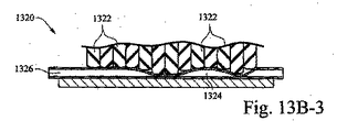
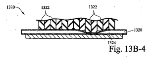
形状変化材料は、蠕動ポンプを形成するのにも適用されてもよい。図13Aは、特定の例の実施形態による例示的なポンプの例示的な断面図である。ポンプ1300は、ゲート1304、1306、および1308を開閉することによって圧送作用を形成するように作用し得る一連の領域1302A、1302B、および1302Cを含む。具体的には、ゲートは、形状変化材料によって形成されてもよく、それによって、ゲートのうちの1つに電荷が印加されると、帯電しているゲートが開いて、1つの領域から別の領域への空気流1303が可能になる。特定の例の実施形態において、ポンプは、例えば、フロージェネレータを患者インターフェースに接続するチューブシステムの一部分であってもよい。特定の例の実施形態において、ポンプは、チューブまたは呼吸補助システムの別のコンポーネントを補完するかまたはそれに付着する異なる部分であってもよい。
Peristaltic pump The shape-changing material may also be applied to form a peristaltic pump. FIG. 13A is an exemplary cross-sectional view of an exemplary pump in accordance with certain example embodiments.
特定の例の実施形態において、ポンプは、形状変化材料から形成されるバルーンを含んでもよく、一連の弁を含むチューブに取り付けられてもよい。バルーンは、圧送作用を生成するために定期的に帯電され得る。バルーンから送られる気体は、その後、定期的に帯電されることによって開閉させられている弁によってチューブに送られ得る。特定の例の実施形態において、弁の開閉を使用して、患者に送出されている圧力を調節することができる。 In certain example embodiments, the pump may include a balloon formed from a shape-changing material and may be attached to a tube that includes a series of valves. The balloon can be periodically charged to create a pumping action. The gas sent from the balloon can then be sent to the tube by a valve that is opened and closed by being periodically charged. In certain example embodiments, the opening and closing of a valve can be used to regulate the pressure being delivered to the patient.
図13B−1〜図13B−4は、特定の例の実施形態による別の例示的なポンプの例示的な断面図である。ポンプ1320は、形状変化材料から形成される複数のフィンガ1322を含んでもよい。フィンガは、可撓性材料1330Aに接触して配置され得る。フィンガ1322および可撓性材料1330Aの反対には、別の可撓性材料1330Bに接触して配置された固体ベース部分1332があり得る。動作時、電荷がフィンガ1322に印加され得、それによって、フィンガの各々は対応する電荷によって高さが変化し得る。高さが変化することによって、2つの可撓性材料1330Aと1330Bとの間にポケット1324が生成され得る。フィンガに印加される電荷は、ポケット1324が空気流送出端部1326(例えば、フロージェネレータ端部)から、図13B−4における空気流受容端部1328へと「移動する」ように調整され得る。したがって、加圧呼吸用気体に対する圧送作用が実行され得る。
13B-1 to 13B-4 are exemplary cross-sectional views of another exemplary pump according to certain example embodiments. The
図14は、特定の例の実施形態による例示的な電気ポリマーに電力を供給するように構成された例示的な電気回路を示す。電気回路1400は、図1Dまたは図4Cのポリマーアクチュエータのような、誘電体電気活性ポリマーアクチュエータ1402を制御するために設けられる。アクチュエータの概念図を1402に示す。アクチュエータは、2つの電極1404Aと1404Bとの間に挟まれたポリマー層1406を含んでもよい。電極は、関連するキャパシタンスCおよびインピーダンスZとともに示されている。ポリマー層1406は、関連する抵抗Rsを有して示されている。他の実施形態は異なる数の層(例えば、1、2、または3)を含んでもよいことは諒解されよう。
FIG. 14 illustrates an example electrical circuit configured to power an example electrical polymer according to certain example embodiments. An
この例の電気回路1400において、DC電圧V1410が、フロージェネレータまたは外部電源のいずれかから供給される。特定の例の実施形態において、供給される電圧は12ボルトまたは24ボルト程度になる。しかしながら、他の電圧値(例えば、より小さい、より大きい、または中間)が使用されてもよいことは諒解されよう。増大した電圧をポリマーに供給するための昇圧モジュール1412が設けられてもよい。例えば、特定の事例において、電圧は1キロボルト以上に昇圧され得る。この電圧は、この電圧は、アクチュエータが内部に実装される特定のシステムに応じて変化してもよいことは諒解されよう。電源1410は、継電器1416を制御するように機能する制御ユニット1414にも電力を提供する。継電器1416を使用することによって、ポリマーに提供される高電圧を、制御ユニット1414から低電圧制御信号を用いてオンおよびオフに切り替えることが可能になる。
In the
電気コントローラは、電荷レベル(提供される電圧または電流)を段階的に制御し、したがって、ポリマー部分の形状および/またはサイズが実質的に段階的に変化するようにするように構成されてもよい。これは、単一の段階、または、複数のより細かい段階を含んでもよい。代替的に、電圧または電流は、連続的に増大(または低減)されてもよく、したがって制御されるポリマーの形状および/またはサイズに漸進的な変化を付与する。これら2つの方法の間の組合せも適用されてもよい。 The electrical controller may be configured to control the charge level (provided voltage or current) in steps, thus causing the shape and / or size of the polymer portion to change substantially in steps. . This may include a single stage or multiple finer stages. Alternatively, the voltage or current may be increased (or decreased) continuously, thus imparting a gradual change in the shape and / or size of the polymer being controlled. Combinations between these two methods may also be applied.
ポリマーに作用する力によって、ポリマーがたわみ、ポリマーアクチュエータと関連付けられる電気インピーダンスが変化し得る。特定の事例において、これによって、特定の実施形態においてポリマーアクチュエータが、そのようなたわみまたは電気インピーダンスに基づく患者への呼吸補助の提供と関連付けられる少なくとも1つのパラメータを検知するのに使用されることが可能になる。この構成において、フラップのポリマーの少なくとも1つの電気的特性の測定された変化が、少なくとも1つのパラメータの関連付けられる変化の指示を提供する。特定の例の実施形態において、インピーダンスの変化の測定値を使用して、フラップ、または、ポリマーを使用する他の呼吸コンポーネントに加えられる圧力の情報を得ることができる。これによって、空気流(例えば、窒息防止通気部400内の)または患者の呼吸の情報がもたらされる。特定の例の実施形態において、電気インピーダンスはフラップ(または他の構造)の位置をも示し得る。例えば、フラップは、それが採用されている位置に応じて異なる圧力下にあり得る。したがって、特定の例の実施形態において、オプションのフィードバックライン「F」1420がアクチュエータからの信号を制御ユニットに提供するために含まれてもよい。抵抗器「RF」1418も、高電圧を制御ユニットにとって許容可能なレベルまで降圧し戻すために使用されてもよい。 The force acting on the polymer can cause the polymer to flex and change the electrical impedance associated with the polymer actuator. In certain cases, this allows a polymer actuator in certain embodiments to be used to sense at least one parameter associated with providing a patient with respiratory assistance based on such deflection or electrical impedance. It becomes possible. In this configuration, a measured change in at least one electrical property of the flap polymer provides an indication of the associated change in at least one parameter. In certain example embodiments, a measurement of the change in impedance can be used to obtain information on pressure applied to a flap or other respiratory component using a polymer. This provides information on airflow (eg, in the anti-suffocation vent 400) or patient breathing. In certain example embodiments, the electrical impedance may also indicate the position of the flap (or other structure). For example, the flap can be under different pressures depending on the position where it is employed. Thus, in certain example embodiments, an optional feedback line “F” 1420 may be included to provide a signal from the actuator to the control unit. Resistor “RF” 1418 may also be used to step down the high voltage back to a level acceptable to the control unit.
特定の例の実施形態において、ポリマーが湾曲してフラップが(例えば、図4Cに示すような)閉位置にあるとき、フィードバックラインFは電気回路1400において、フロージェネレータ回路の患者端部における治療圧力を検知するのに使用されてもよい。言い換えれば、ポリマーアクチュエータの総電気インピーダンスの増大によって、抵抗器1418庭たる電圧および電流が変化する。抵抗器1418にわたるこの電流または電圧の変化を検知すること、および、そのような変化と治療圧力の対応する変化との間の所定の関係を使用することによって、治療圧力を推定することができる。そのような実施態様は、ポリマーが図4Aの開位置にあるときに、ユーザ呼吸に起因する圧力の変化を検出するのにも使用されてもよい。
In certain example embodiments, when the polymer is curved and the flap is in the closed position (eg, as shown in FIG. 4C), the feedback line F is in the
特定の例の実施形態において、抵抗器1418は、加熱空気をチューブに(例えば、患者の快適性を増大させるために)提供するように構成されてもよい。特定の例の実施形態において、補助コントローラSC(図示せず)が主ポリマー制御ユニット1414への入力を提供することができる。補助コントローラは、圧力信号またはフロー信号または温度信号または他の信号のような、フロージェネレータ(図示せず)からの入力をとって、この情報を使用してポリマーを(例えば、図4Cに示すそれぞれの部分から)いつ起動すべきかを判定することができる。例えば、治療圧力が低すぎて通気式システムにおいて十分な通気流を提供することができないと補助コントローラが判定した場合、ポリマーは、電気刺激を介して、ユーザが増大した(例えば、十分な)通気を可能にするための様々な位置(例えば、図4Cに示すような)に調整され得る。代替的に、補助コントローラは、ポリマーの位置またはポリマーの形状の連続的な制御を可能にするように、昇圧回路に対する入力電圧を制御するのに使用されてもよい。図14に示す回路は、本明細書に論じる様々な他の実施形態とともに動作するように構成されてもよいことは理解されよう。
In certain example embodiments,
特定の例の実施形態において、呼吸補助システムのコンポーネント内の形状変化材料は、1)長さ、2)幅、または3)深さ/高さにおいて形状が変化してもよい。言い換えれば、形状の変化は、特定の用途に応じて、一次元、二次元、または三次元であってもよい。特定の事例において、材料の断面積は、面積が増大または低減してもよい。 In certain example embodiments, the shape-changing material in the components of the respiratory assistance system may change shape in 1) length, 2) width, or 3) depth / height. In other words, the shape change may be one-dimensional, two-dimensional, or three-dimensional, depending on the particular application. In certain cases, the cross-sectional area of the material may increase or decrease in area.
開示された技術は、現在最も実用的で好ましい実施形態であると考えられるものに関連して説明されているが、本技術は、開示された実施形態に限定されるべきではなく、逆に、本技術の精神および範囲内に含まれる様々な変更および均等な構成をカバーするように意図されていることは理解されたい。さらに、本技術はOSAを患っている患者に対する特定の用途を有するが、他の疾患(例えば、鬱血性心不全、糖尿病、病的肥満、脳卒中、肥満手術など)を患っている患者が、上記の教示から利益を導き出すことができることは諒解されたい。さらに、上記の教示は、非医療用途において、患者および非患者との同様の適用可能性を有する。 Although the disclosed technology has been described in connection with what is presently considered to be the most practical and preferred embodiments, the technology should not be limited to the disclosed embodiments, and conversely It should be understood that various modifications and equivalent arrangements included within the spirit and scope of the present technology are intended to be covered. Furthermore, although the technology has particular application to patients suffering from OSA, patients suffering from other diseases (eg congestive heart failure, diabetes, morbid obesity, stroke, bariatric surgery, etc.) It should be appreciated that benefits can be derived from teachings. Furthermore, the above teachings have similar applicability with patients and non-patients in non-medical applications.
102 ストラップ
104 導管
106 電荷
108 患者インターフェース
109 コネクタ
120 ストラップ
122 形状
124 形状
126 電荷
130 形状
131 誘電体ポリマー
131’ 誘電体ポリマー
132 形状
133 電極層
134 ストラップ
135 電気活性ポリマー層、中心ポリマー層、ポリマー部分
136 電荷
137 電源
139 電圧
141 患者インターフェース
142 頂点
143 ホース(チューブ)
144 導管
146 導管
148 電荷
200 チューブ、管類
202 空気流路
204 電荷
210 導管、チューブ
212 形状変化材料
214 電荷
220 導管
220’ 導管
222 膜
224 電気活性ポリマーストリップ
224−A 誘電体層
224−A’ 電極層
224−B ポリマー
224−B’ ポリマー層
240 導管
240’ 導管
242 膜
242’ 膜
244 電気活性ポリマーストリップ
244’ 電気活性ポリマーストリップ
400 窒息防止通気部(通気部)
402 開口
406 患者側端部
408 フラップ
420 フラップ
420’ フラップ
422 電極
422A’ 電極
422B’ 電極
424 抑制層
424’ 抑制層
426 ポリマー層
426’ ポリマー
610 通気部
612 形状変化材料
614 孔
616 電荷
650 通気部
650’ 通気部
652 誘電体ポリマー層
652’ 誘電体ポリマー
654 電極
656 通気開口
656’ 通気開口
702 患者インターフェース
704 前頭部支持パッド
706 電荷
820 クッション
822A クッション領域
822B クッション領域
822C クッション領域
822D クッション領域(右頬領域)
824 パルス
826 パルス
842 患者インターフェース
844 吸入
845 チューブ
846 クッション、形状変化材料
848 電荷
850 通気孔
852 チャンバ
854 空気流路、グラフ
860 患者インターフェース
863 鼻梁
864 形状変化材料
865 鼻梁
866 材料
868 電荷
870 患者インターフェース
872 クッション
874 電荷
876 チャネル
880 フローシステム
882 カフ部分
884 電荷
886 屈曲部分
900 屈曲部
902 アーム部分
903A 位置
903B 位置
904 電荷
906 インターフェース部分
1002 睡眠マット
1004 電荷
1100 フロージェネレータ
1102 ハウジング
1104 電荷
1200 スプリント
1202 電荷
1300 ポンプ
1302A 領域
1302B 領域
1303 空気流
1304 ゲート
1306 ゲート
1320 ポンプ
1322 フィンガ
1324 ポケット
1326 空気流送出端部
1328 空気流受容端部
1330A 可撓性材料
1330B 可撓性材料
1332 固体ベース部分
1400 電気回路
1402 誘電体電気活性ポリマーアクチュエータ
1404A 電極
1404B 電極
1406 ポリマー層
1410 電源
1412 昇圧モジュール
1414 制御ユニット
1416 継電器
1418 抵抗器
102
144
402
824
Claims (18)
前記第1導管の電気活性ポリマーおよび前記第2導管の電気活性ポリマーは、患者に提供される呼吸補助の態様を変更または維持するように、各導管の形状およびサイズの少なくとも一方を変化させるために、選択的に励起可能であり、
前記第1導管および前記第2導管の一方における流れの減少検出に応じて、前記第1導管および前記第2導管のうちの少なくとも1つが励起される、呼吸補助コンポーネント。 A respiratory assistance component comprising a first conduit and a second conduit , wherein each of the first conduit and the second conduit is configured to supply a breathing gas to a patient, the first conduit and the second conduit Each of the second conduits comprises an electroactive polymer , and the electroactive polymer includes a first unexcited state when no voltage or current is applied to the electroactive polymer, and The shape and / or size change between the second excited state when a voltage or current is applied;
The electroactive polymer of the first conduit and the electroactive polymer of the second conduit are for changing at least one of the shape and size of each conduit so as to change or maintain the manner of respiratory assistance provided to the patient. Is selectively excitable,
A respiratory assistance component , wherein at least one of the first conduit and the second conduit is excited in response to detecting a decrease in flow in one of the first conduit and the second conduit .
各導管の可撓性管状本体が、各らせん形状電気活性ポリマーストリップの第1状態から第2状態への変化に従って、径方向および/または軸方向に膨張するように構成された、請求項3に記載の呼吸補助コンポーネント。 The first and second conduits comprise a flexible tubular body, and the electroactive polymer of at least one of the first and second conduits is disposed in each flexible tubular body. Including electroactive polymer strips of
Flexible tubular body of each conduit in accordance with the change from the first state of each spiral-shaped electroactive polymer strip to the second state, is configured to expand radially and / or axially, to claim 3 Respiratory aid component as described.
患者の口、鼻、または口および鼻の周りに、シールを形成するように構成された患者インターフェースと、
請求項1から17のいずれか一項に記載の呼吸補助コンポーネントと、
を備え、前記第1導管および前記第2導管の少なくとも一方が、前記患者インターフェースに呼吸用気体を供給するように構成された持続的気道陽圧(CPAP)システム。 A continuous positive airway pressure (CPAP) system,
A patient interface configured to form a seal around the patient's mouth, nose, or mouth and nose;
A respiratory assistance component according to any one of claims 1 to 17 ,
A continuous positive airway pressure (CPAP) system, wherein at least one of the first conduit and the second conduit is configured to supply respiratory gas to the patient interface.
Applications Claiming Priority (3)
| Application Number | Priority Date | Filing Date | Title |
|---|---|---|---|
| US201161557134P | 2011-11-08 | 2011-11-08 | |
| US61/557,134 | 2011-11-08 | ||
| PCT/AU2012/001369 WO2013067582A1 (en) | 2011-11-08 | 2012-11-08 | Electrically stimulated respiratory assistance components |
Publications (3)
| Publication Number | Publication Date |
|---|---|
| JP2014534875A JP2014534875A (en) | 2014-12-25 |
| JP2014534875A5 JP2014534875A5 (en) | 2015-12-24 |
| JP6181658B2 true JP6181658B2 (en) | 2017-08-16 |
Family
ID=48288371
Family Applications (1)
| Application Number | Title | Priority Date | Filing Date |
|---|---|---|---|
| JP2014540272A Expired - Fee Related JP6181658B2 (en) | 2011-11-08 | 2012-11-08 | Electrical stimulation respiratory assist component |
Country Status (6)
| Country | Link |
|---|---|
| US (4) | US9687619B2 (en) |
| EP (1) | EP2776102B1 (en) |
| JP (1) | JP6181658B2 (en) |
| CN (1) | CN104302337B (en) |
| AU (1) | AU2012334808B2 (en) |
| WO (1) | WO2013067582A1 (en) |
Families Citing this family (38)
| Publication number | Priority date | Publication date | Assignee | Title |
|---|---|---|---|---|
| WO2005079726A1 (en) | 2004-02-23 | 2005-09-01 | Fisher & Paykel Healthcare Limited | Breathing assistance apparatus |
| WO2005094928A1 (en) | 2004-04-02 | 2005-10-13 | Fisher & Paykel Healthcare Limited | Breathing assistance apparatus |
| US9072852B2 (en) | 2004-04-02 | 2015-07-07 | Fisher & Paykel Healthcare Limited | Breathing assistance apparatus |
| ES2954589T3 (en) | 2006-07-14 | 2023-11-23 | Fisher & Paykel Healthcare Ltd | Respiratory assistance device |
| US10258757B2 (en) | 2008-05-12 | 2019-04-16 | Fisher & Paykel Healthcare Limited | Patient interface and aspects thereof |
| US10792451B2 (en) | 2008-05-12 | 2020-10-06 | Fisher & Paykel Healthcare Limited | Patient interface and aspects thereof |
| US11660413B2 (en) | 2008-07-18 | 2023-05-30 | Fisher & Paykel Healthcare Limited | Breathing assistance apparatus |
| WO2010041966A1 (en) | 2008-10-10 | 2010-04-15 | Fisher & Paykel Healthcare Limited | Nasal pillows for a patient interface |
| US10137271B2 (en) | 2009-11-18 | 2018-11-27 | Fisher & Paykel Healthcare Limited | Nasal interface |
| EP4070841A1 (en) | 2010-10-08 | 2022-10-12 | Fisher & Paykel Healthcare Limited | Breathing assistance apparatus |
| US10603456B2 (en) | 2011-04-15 | 2020-03-31 | Fisher & Paykel Healthcare Limited | Interface comprising a nasal sealing portion |
| EP3117861B1 (en) | 2011-04-15 | 2021-03-31 | Fisher&Paykel Healthcare Limited | Interface comprising a rolling nasal bridge portion |
| NZ759284A (en) * | 2011-06-21 | 2021-07-30 | ResMed Pty Ltd | Pap system |
| EP2776102B1 (en) | 2011-11-08 | 2019-08-07 | ResMed Pty Ltd | Electrically stimulated respiratory assistance components |
| US10046131B2 (en) | 2012-06-08 | 2018-08-14 | Koninklijke Philips N.V. | Patient interface with cushion for red mark prevention |
| CA3142517A1 (en) | 2012-08-08 | 2014-02-13 | Fisher & Paykel Healthcare Limited | Headgear for patient interface |
| US9950130B2 (en) | 2012-09-04 | 2018-04-24 | Fisher & Paykel Healthcare Limited | Valsalva mask |
| WO2015130180A1 (en) * | 2014-02-26 | 2015-09-03 | Fisher & Paykel Healthcare Limited | Sealing force detection enabled, therapeutic fluid delivery device |
| WO2015196255A1 (en) | 2014-06-27 | 2015-12-30 | Resmed Limited | Auto-fit mask |
| AU2015307325A1 (en) | 2014-08-25 | 2017-04-06 | Fisher & Paykel Healthcare Limited | Respiratory mask and related portions, components or sub-assemblies |
| US9925347B2 (en) | 2014-10-02 | 2018-03-27 | Koninklijke Philips N.V. | Cushion element for a patient interface |
| US10744295B2 (en) | 2015-01-13 | 2020-08-18 | ResMed Pty Ltd | Respiratory therapy apparatus |
| SG10201909092SA (en) | 2015-03-31 | 2019-11-28 | Fisher & Paykel Healthcare Ltd | A user interface and system for supplying gases to an airway |
| US11266803B2 (en) | 2015-06-05 | 2022-03-08 | Koninklijke Philips N.V. | Tubing assembly for patient interface device and elements for improving the fit and feel of such assembly |
| GB201510384D0 (en) * | 2015-06-13 | 2015-07-29 | Young Peter J | Medical gas delivery system |
| WO2017199215A1 (en) * | 2016-05-19 | 2017-11-23 | Trudell Medical International | Smart valved holding chamber |
| CN114569856A (en) * | 2016-08-11 | 2022-06-03 | 费雪派克医疗保健有限公司 | Collapsible catheter, patient interface and headgear connector |
| EP3522967B1 (en) * | 2016-10-04 | 2020-11-11 | Koninklijke Philips N.V. | Magnetic anti-crush feature for conduit |
| US11103665B2 (en) * | 2016-11-09 | 2021-08-31 | Koninklijke Philips N.V. | Respiratory apparatus and method of operating the respiratory apparatus |
| USD823454S1 (en) | 2017-02-23 | 2018-07-17 | Fisher & Paykel Healthcare Limited | Cushion assembly for breathing mask assembly |
| USD823455S1 (en) | 2017-02-23 | 2018-07-17 | Fisher & Paykel Healthcare Limited | Cushion assembly for breathing mask assembly |
| USD824020S1 (en) | 2017-02-23 | 2018-07-24 | Fisher & Paykel Healthcare Limited | Cushion assembly for breathing mask assembly |
| AU2019280153A1 (en) | 2018-06-04 | 2020-12-17 | Trudell Medical International Inc. | Smart valved holding chamber |
| USD924388S1 (en) * | 2018-07-10 | 2021-07-06 | ResMed Pty Ltd | Patient interface |
| USD942614S1 (en) * | 2018-07-10 | 2022-02-01 | ResMed Pty Ltd | Combined cushion and frame module for patient interface |
| USD942615S1 (en) | 2018-09-12 | 2022-02-01 | ResMed Pty Ltd | Patient interface |
| WO2023026203A1 (en) * | 2021-08-25 | 2023-03-02 | Fisher & Paykel Healthcare Limited | Patient interface gas sampling and accessory for patient interface |
| CN113877033B (en) * | 2021-12-09 | 2022-02-18 | 南京舒普思达医疗设备有限公司 | Breathing machine regulation and control method and system based on sleep characteristics |
Family Cites Families (36)
| Publication number | Priority date | Publication date | Assignee | Title |
|---|---|---|---|---|
| WO1982003548A1 (en) * | 1981-04-24 | 1982-10-28 | Sullivan Colin Edward | Device for treating snoring sickness |
| US5485850A (en) * | 1993-08-13 | 1996-01-23 | Dietz; Henry G. | Monitor of low pressure intervals with control capabilities |
| US5551419A (en) * | 1994-12-15 | 1996-09-03 | Devilbiss Health Care, Inc. | Control for CPAP apparatus |
| US5538000A (en) * | 1995-02-06 | 1996-07-23 | Hans Rudolph, Inc. | Airflow delivery system |
| US20070137653A1 (en) * | 2000-03-13 | 2007-06-21 | Wood Thomas J | Ventilation interface for sleep apnea therapy |
| ATE328629T1 (en) | 2001-09-24 | 2006-06-15 | Atsuo F Fukunaga | BREATHING CIRCUIT WITH UNCONVENTIONAL BREATHING LINES AND SYSTEMS AND METHODS FOR OPTIMIZING THE USE OF FRESH GASES |
| AU2003223231A1 (en) | 2002-03-05 | 2003-12-31 | Sri International | Electroactive polymer devices for controlling fluid flow |
| US6679836B2 (en) * | 2002-06-21 | 2004-01-20 | Scimed Life Systems, Inc. | Universal programmable guide catheter |
| US7947000B2 (en) * | 2003-09-12 | 2011-05-24 | Intuitive Surgical Operations, Inc. | Cannula system for free-space navigation and method of use |
| US8298161B2 (en) * | 2002-09-12 | 2012-10-30 | Intuitive Surgical Operations, Inc. | Shape-transferring cannula system and method of use |
| EP1558321B1 (en) | 2002-11-06 | 2016-07-13 | ResMed Limited | Mask and components thereof |
| US7114497B2 (en) * | 2003-07-18 | 2006-10-03 | Acoba, Llc | Method and system of individually controlling airway pressure of a patient's nares |
| JP2007532205A (en) | 2004-04-15 | 2007-11-15 | レスメド リミテッド | Positive pressure breathing device conduit |
| EP1787575A1 (en) * | 2004-09-07 | 2007-05-23 | Olympus Corporation | Endoscope |
| US7882842B2 (en) * | 2004-09-21 | 2011-02-08 | Pavad Medical, Inc. | Airway implant sensors and methods of making and using the same |
| US7559951B2 (en) * | 2004-09-30 | 2009-07-14 | Depuy Products, Inc. | Adjustable, remote-controllable orthopaedic prosthesis and associated method |
| JP2006187517A (en) | 2005-01-07 | 2006-07-20 | Omron Healthcare Co Ltd | Air valve, electronic hemomanometer and air massage machine |
| US20060169281A1 (en) | 2005-02-03 | 2006-08-03 | Aylsworth Alonzo C | Continuous flow selective delivery of therapeutic gas |
| TWI378791B (en) | 2005-06-08 | 2012-12-11 | Convatec Technologies Inc | A cuff for providing compression to a limb, a channel for use in a compression device and use of a separating means in the manufacture of the cuff and the channel |
| US7766815B2 (en) * | 2005-07-28 | 2010-08-03 | Ethicon Endo-Surgery, Inc. | Electroactive polymer actuated gastric band |
| JP2009507617A (en) * | 2005-09-14 | 2009-02-26 | ネオガイド システムズ, インコーポレイテッド | Method and apparatus for performing transluminal and other operations |
| US8211088B2 (en) * | 2005-10-14 | 2012-07-03 | Boston Scientific Scimed, Inc. | Catheter with controlled lumen recovery |
| US20070219576A1 (en) * | 2006-03-16 | 2007-09-20 | Medtronic Vascular, Inc. | Reversibly and Radially Expandable Electroactive Polymer Element for Temporary Occlusion of a Vessel |
| US7397166B1 (en) | 2006-04-12 | 2008-07-08 | Pacesetter, Inc. | Electroactive polymer-actuated peristaltic pump and medical lead incorporating such a pump |
| US8439961B2 (en) * | 2006-07-31 | 2013-05-14 | Boston Scientific Scimed, Inc. | Stent retaining mechanisms |
| JP5230156B2 (en) * | 2006-09-21 | 2013-07-10 | レスメド・リミテッド | Headgear stretched for breathing mask |
| US8012127B2 (en) * | 2007-02-28 | 2011-09-06 | Medtronic, Inc. | Systems and methods for gaining access around an implanted medical device |
| US20090101153A1 (en) * | 2007-10-18 | 2009-04-23 | Searete Llc, A Limited Liability Corporation Of The State Of Delaware | Method of facilitated airway intubation |
| JP5623291B2 (en) * | 2008-01-04 | 2014-11-12 | ボストン サイエンティフィック サイムド,インコーポレイテッドBoston Scientific Scimed,Inc. | Separation mechanism for implantable devices |
| EP3075406A1 (en) * | 2008-04-30 | 2016-10-05 | ResMed R&D Germany GmbH | Apparatus and method for controlled delivery of a breathing gas to the respiratory tracts of a user |
| DE102009036424A1 (en) * | 2009-08-06 | 2011-02-10 | Richard Wolf Gmbh | Endoscopic instrument |
| US8408210B2 (en) * | 2009-12-18 | 2013-04-02 | Covidien Lp | Cuffless tracheal tube |
| US8327851B2 (en) | 2010-03-15 | 2012-12-11 | Sleepnea Llc | Respiratory mask with user interface |
| EP2378121A1 (en) * | 2010-04-16 | 2011-10-19 | Veinux ApS | Pump element for a tube pump |
| US20130019374A1 (en) | 2011-01-04 | 2013-01-24 | Schwartz Alan N | Gel-based seals and fixation devices and associated systems and methods |
| EP2776102B1 (en) | 2011-11-08 | 2019-08-07 | ResMed Pty Ltd | Electrically stimulated respiratory assistance components |
-
2012
- 2012-11-08 EP EP12848263.5A patent/EP2776102B1/en active Active
- 2012-11-08 JP JP2014540272A patent/JP6181658B2/en not_active Expired - Fee Related
- 2012-11-08 US US14/357,127 patent/US9687619B2/en active Active
- 2012-11-08 WO PCT/AU2012/001369 patent/WO2013067582A1/en active Application Filing
- 2012-11-08 CN CN201280066285.8A patent/CN104302337B/en active Active
- 2012-11-08 AU AU2012334808A patent/AU2012334808B2/en active Active
-
2017
- 2017-05-09 US US15/590,415 patent/US10806875B2/en active Active
-
2020
- 2020-03-15 US US16/819,137 patent/US11684733B2/en active Active
-
2023
- 2023-05-04 US US18/312,295 patent/US20230270958A1/en active Pending
Also Published As
| Publication number | Publication date |
|---|---|
| EP2776102B1 (en) | 2019-08-07 |
| US10806875B2 (en) | 2020-10-20 |
| US20230270958A1 (en) | 2023-08-31 |
| US20170239430A1 (en) | 2017-08-24 |
| JP2014534875A (en) | 2014-12-25 |
| AU2012334808A1 (en) | 2014-05-22 |
| EP2776102A1 (en) | 2014-09-17 |
| AU2012334808B2 (en) | 2015-10-01 |
| US20140311492A1 (en) | 2014-10-23 |
| CN104302337B (en) | 2017-03-08 |
| US9687619B2 (en) | 2017-06-27 |
| CN104302337A (en) | 2015-01-21 |
| NZ624510A (en) | 2015-12-24 |
| US11684733B2 (en) | 2023-06-27 |
| EP2776102A4 (en) | 2015-04-29 |
| WO2013067582A1 (en) | 2013-05-16 |
| US20200215277A1 (en) | 2020-07-09 |
Similar Documents
| Publication | Publication Date | Title |
|---|---|---|
| JP6181658B2 (en) | Electrical stimulation respiratory assist component | |
| US11090458B2 (en) | Auto-feedback valve for a sleep apnea device | |
| JP7071571B2 (en) | Adjustable headgear tubing for patient interface | |
| US11766532B2 (en) | Auto-fit mask | |
| US10272226B2 (en) | Auto-feedback valve for a sleep apnea device | |
| EP2996753B1 (en) | Auto-feedback valve for a sleep apnea device | |
| US20230241342A1 (en) | Adjustable headgear tubing for a patient interface | |
| EP4221794A1 (en) | Patient interface and components thereof | |
| NZ624510B2 (en) | Electrically stimulated respiratory assistance components | |
| EP4221797A1 (en) | Variable flow vent assembly for a conduit mask | |
| CN117919561A (en) | Adjustable headgear tube for patient interface |
Legal Events
| Date | Code | Title | Description |
|---|---|---|---|
| A521 | Request for written amendment filed |
Free format text: JAPANESE INTERMEDIATE CODE: A523 Effective date: 20151106 |
|
| A621 | Written request for application examination |
Free format text: JAPANESE INTERMEDIATE CODE: A621 Effective date: 20151106 |
|
| A131 | Notification of reasons for refusal |
Free format text: JAPANESE INTERMEDIATE CODE: A131 Effective date: 20161031 |
|
| A521 | Request for written amendment filed |
Free format text: JAPANESE INTERMEDIATE CODE: A523 Effective date: 20170130 |
|
| TRDD | Decision of grant or rejection written | ||
| A01 | Written decision to grant a patent or to grant a registration (utility model) |
Free format text: JAPANESE INTERMEDIATE CODE: A01 Effective date: 20170626 |
|
| A61 | First payment of annual fees (during grant procedure) |
Free format text: JAPANESE INTERMEDIATE CODE: A61 Effective date: 20170720 |
|
| R150 | Certificate of patent or registration of utility model |
Ref document number: 6181658 Country of ref document: JP Free format text: JAPANESE INTERMEDIATE CODE: R150 |
|
| S533 | Written request for registration of change of name |
Free format text: JAPANESE INTERMEDIATE CODE: R313533 |
|
| R350 | Written notification of registration of transfer |
Free format text: JAPANESE INTERMEDIATE CODE: R350 |
|
| R250 | Receipt of annual fees |
Free format text: JAPANESE INTERMEDIATE CODE: R250 |
|
| R250 | Receipt of annual fees |
Free format text: JAPANESE INTERMEDIATE CODE: R250 |
|
| LAPS | Cancellation because of no payment of annual fees |