JP2007532205A - Positive pressure breathing device conduit - Google Patents
Positive pressure breathing device conduit Download PDFInfo
- Publication number
- JP2007532205A JP2007532205A JP2007507626A JP2007507626A JP2007532205A JP 2007532205 A JP2007532205 A JP 2007532205A JP 2007507626 A JP2007507626 A JP 2007507626A JP 2007507626 A JP2007507626 A JP 2007507626A JP 2007532205 A JP2007532205 A JP 2007532205A
- Authority
- JP
- Japan
- Prior art keywords
- conduit
- headgear
- patient
- head
- wall
- Prior art date
- Legal status (The legal status is an assumption and is not a legal conclusion. Google has not performed a legal analysis and makes no representation as to the accuracy of the status listed.)
- Withdrawn
Links
Images


Classifications
-
- A—HUMAN NECESSITIES
- A61—MEDICAL OR VETERINARY SCIENCE; HYGIENE
- A61M—DEVICES FOR INTRODUCING MEDIA INTO, OR ONTO, THE BODY; DEVICES FOR TRANSDUCING BODY MEDIA OR FOR TAKING MEDIA FROM THE BODY; DEVICES FOR PRODUCING OR ENDING SLEEP OR STUPOR
- A61M16/00—Devices for influencing the respiratory system of patients by gas treatment, e.g. mouth-to-mouth respiration; Tracheal tubes
- A61M16/06—Respiratory or anaesthetic masks
- A61M16/0666—Nasal cannulas or tubing
-
- A—HUMAN NECESSITIES
- A61—MEDICAL OR VETERINARY SCIENCE; HYGIENE
- A61M—DEVICES FOR INTRODUCING MEDIA INTO, OR ONTO, THE BODY; DEVICES FOR TRANSDUCING BODY MEDIA OR FOR TAKING MEDIA FROM THE BODY; DEVICES FOR PRODUCING OR ENDING SLEEP OR STUPOR
- A61M16/00—Devices for influencing the respiratory system of patients by gas treatment, e.g. mouth-to-mouth respiration; Tracheal tubes
- A61M16/06—Respiratory or anaesthetic masks
- A61M16/0605—Means for improving the adaptation of the mask to the patient
- A61M16/0611—Means for improving the adaptation of the mask to the patient with a gusset portion
-
- A—HUMAN NECESSITIES
- A61—MEDICAL OR VETERINARY SCIENCE; HYGIENE
- A61M—DEVICES FOR INTRODUCING MEDIA INTO, OR ONTO, THE BODY; DEVICES FOR TRANSDUCING BODY MEDIA OR FOR TAKING MEDIA FROM THE BODY; DEVICES FOR PRODUCING OR ENDING SLEEP OR STUPOR
- A61M16/00—Devices for influencing the respiratory system of patients by gas treatment, e.g. mouth-to-mouth respiration; Tracheal tubes
- A61M16/06—Respiratory or anaesthetic masks
- A61M16/0683—Holding devices therefor
-
- A—HUMAN NECESSITIES
- A61—MEDICAL OR VETERINARY SCIENCE; HYGIENE
- A61M—DEVICES FOR INTRODUCING MEDIA INTO, OR ONTO, THE BODY; DEVICES FOR TRANSDUCING BODY MEDIA OR FOR TAKING MEDIA FROM THE BODY; DEVICES FOR PRODUCING OR ENDING SLEEP OR STUPOR
- A61M16/00—Devices for influencing the respiratory system of patients by gas treatment, e.g. mouth-to-mouth respiration; Tracheal tubes
- A61M16/08—Bellows; Connecting tubes ; Water traps; Patient circuits
- A61M16/0816—Joints or connectors
- A61M16/0833—T- or Y-type connectors, e.g. Y-piece
-
- A—HUMAN NECESSITIES
- A61—MEDICAL OR VETERINARY SCIENCE; HYGIENE
- A61M—DEVICES FOR INTRODUCING MEDIA INTO, OR ONTO, THE BODY; DEVICES FOR TRANSDUCING BODY MEDIA OR FOR TAKING MEDIA FROM THE BODY; DEVICES FOR PRODUCING OR ENDING SLEEP OR STUPOR
- A61M16/00—Devices for influencing the respiratory system of patients by gas treatment, e.g. mouth-to-mouth respiration; Tracheal tubes
- A61M16/06—Respiratory or anaesthetic masks
- A61M2016/0661—Respiratory or anaesthetic masks with customised shape
-
- A—HUMAN NECESSITIES
- A61—MEDICAL OR VETERINARY SCIENCE; HYGIENE
- A61M—DEVICES FOR INTRODUCING MEDIA INTO, OR ONTO, THE BODY; DEVICES FOR TRANSDUCING BODY MEDIA OR FOR TAKING MEDIA FROM THE BODY; DEVICES FOR PRODUCING OR ENDING SLEEP OR STUPOR
- A61M2205/00—General characteristics of the apparatus
- A61M2205/02—General characteristics of the apparatus characterised by a particular materials
- A61M2205/0238—General characteristics of the apparatus characterised by a particular materials the material being a coating or protective layer
Abstract
陽圧下の供給気体(408)を送るための導管(12,152,400)は、第1の導管端部(28,404)および第2の導管端部(40,406)を有する導管壁(402)を備える。第1の導管端部(28,404)は、気体供給部(408)に取り付けられるようになされる。導管壁(402)は、(1)導管壁(402)が導管通路(410)を形成し、それに沿って供給気体が第1の導管端部(28,404)から第2の導管端部(40,406)の間で移動することができる開いた状態と、(2)導管壁(402)が導管通路(410)を実質的につぶす、つぶれた状態との間で変形可能である。 The conduit (12,152,400) for delivering the feed gas (408) under positive pressure comprises a conduit wall (402) having a first conduit end (28,404) and a second conduit end (40,406). The first conduit end (28, 404) is adapted to be attached to the gas supply (408). The conduit wall (402) comprises: (1) the conduit wall (402) forms a conduit passageway (410) along which the supply gas flows from the first conduit end (28,404) to the second conduit end (40,406). Between an open state that can move between and a collapsed state in which the conduit wall (402) substantially collapses the conduit passageway (410).
Description
本発明は、陽圧呼吸(PAP)装置の導管に関する。本発明はまた、そのような導管を備えるヘッドギア、およびそのような導管を備えるノーズピースに関する。 The present invention relates to conduits for positive pressure breathing (PAP) devices. The invention also relates to a headgear comprising such a conduit and a nosepiece comprising such a conduit.
本出願は、参照によりその全体を本明細書に組み込む、2004年4月15日出願の濠国特許仮出願第2004902020号の利益を主張する。 This application claims the benefit of Korean Patent Provisional Application No. 2004902020, filed April 15, 2004, which is incorporated herein by reference in its entirety.
閉塞性睡眠無呼吸の治療で使用されるCPAP装置の導入における患者の成功または失敗に影響を及ぼす主な要因の1つは、そのような装置に付随するヘッドギアおよび供給導管の不快感に対処する患者の能力である。 One of the main factors affecting patient success or failure in the introduction of CPAP devices used in the treatment of obstructive sleep apnea addresses headgear and supply conduit discomfort associated with such devices It is patient ability.
そのような装置は、睡眠中に動き、また寝返りをうつ患者の能力を制限しがちとなり、患者の潜在的な不快感を増す可能性がある。 Such devices tend to move during sleep and tend to limit the patient's ability to turn over and increase the patient's potential discomfort.
したがって、そのような装置の欠点を少なくともいくつか克服または改善すること、あるいは有用な代替物を提供することの必要性が当業界において高まってきている。 Accordingly, there is a growing need in the art to overcome or ameliorate at least some of the shortcomings of such devices, or to provide useful alternatives.
本発明の一態様は、陽圧下の供給気体を送達するための導管に関する。この導管は、第1の導管端部および第2の導管端部を有する導管壁を備える。第1の導管端部は、気体供給部に取り付けられるようになされる。導管壁は、(a)導管壁が導管通路を形成し、それに沿って供給気体が第1の導管端部から第2の導管端部までの間で移動することができる開いた状態と、(b)導管壁が導管通路を実質的につぶす、つぶれた状態との間で変形可能である。 One aspect of the invention relates to a conduit for delivering a feed gas under positive pressure. The conduit includes a conduit wall having a first conduit end and a second conduit end. The first conduit end is adapted to be attached to a gas supply. The conduit wall is (a) an open state in which the conduit wall forms a conduit passage along which the feed gas can travel between the first conduit end and the second conduit end; b) The conduit wall is deformable between a collapsed state that substantially collapses the conduit passage.
本発明の別の態様は、陽圧下の供給気体を患者へと送達するためのヘッドギアに関する。このヘッドギアは、気体供給部に取り付けるようになされた結合装置を備える。1対の側部は、患者の頭部の両側に沿って延びるようになされる。各側部は、結合装置に取り付けられた第1の導管端部と、患者の鼻に隣接して配置されるようになされた第2の導管端部とを有する導管を形成する。頭部取り付け構造体は、ヘッドギアを患者の頭部に取り外し可能に固定するようになされる。 Another aspect of the invention relates to a headgear for delivering a supply gas under positive pressure to a patient. The headgear includes a coupling device adapted to be attached to a gas supply. The pair of sides is adapted to extend along both sides of the patient's head. Each side forms a conduit having a first conduit end attached to the coupling device and a second conduit end adapted to be positioned adjacent to the patient's nose. The head mounting structure is adapted to removably secure the headgear to the patient's head.
本発明の別の態様は、陽圧下の供給気体を患者に送達するための鼻用アセンブリに関する。鼻用アセンブリは、気体供給部に取り付けるようになされた結合装置と、患者の鼻に係合するようになされたノーズピースと、患者の頭部の両側に沿って延びるようになされた1対の側部を備える。各側部はそれぞれ、結合装置に取り付けられた第1の導管端部と、ノーズピースに結合されるようにされた第2の導管端部とを有する導管を形成する。頭部取り付け構造体は、ヘッドギアを患者の頭部に取り外し可能に固定するようになされる。 Another aspect of the invention relates to a nasal assembly for delivering a supply gas under positive pressure to a patient. The nasal assembly includes a coupling device adapted to be attached to the gas supply, a nosepiece adapted to engage the patient's nose, and a pair of arms adapted to extend along both sides of the patient's head. With side parts. Each side forms a conduit having a first conduit end attached to the coupling device and a second conduit end adapted to be coupled to the nosepiece. The head mounting structure is adapted to removably secure the headgear to the patient's head.
本発明の別の態様は、陽圧下の供給気体を送達するために導管を使用する方法に関する。この方法は、第1の導管端部と第2の導管端部とを有する導管壁を備える導管を提供することを含む。導管壁は、(a)導管壁が導管通路を形成し、それに沿って第1の導管端部と第2の導管端部の間で供給気体が移動することができる開いた状態と、(b)導管壁が導管通路を実質的につぶす、つぶれた状態との間で変形することができる。この方法は、導管の第1の導管端部を気体供給部に結合させることと、供給気体によって導管壁が開いた状態にされ、供給気体が第1の導管端部から第2の導管端部へと移動することが可能になるように、供給気体を第1の導管端部を通して導管内へと送達することと、導管の第2の導管端部を、そこに供給気体が送達されるべき位置に配置することとを含む。 Another aspect of the invention relates to a method of using a conduit to deliver a feed gas under positive pressure. The method includes providing a conduit comprising a conduit wall having a first conduit end and a second conduit end. The conduit wall is (a) an open state in which the conduit wall forms a conduit passage along which supply gas can move between the first conduit end and the second conduit end; and (b ) The conduit wall can deform between a collapsed state, which substantially collapses the conduit passage. The method includes coupling a first conduit end of a conduit to a gas supply and causing the supply gas to open a conduit wall so that the supply gas passes from the first conduit end to the second conduit end. The feed gas should be delivered through the first conduit end into the conduit and the second conduit end of the conduit to which the feed gas should be delivered Placing in position.
本発明の別の態様は、陽圧下の供給気体を患者に送達するヘッドギアを構成するための方法に関する。この方法は、供給気体がそれに沿って移動することができる導管通路を形成する、少なくとも1つの導管を備えるヘッドギアを提供することと、特定の患者の頭部形状をマッピングすることと、特定の患者の頭部上にヘッドギアが実質的に密着しかつ快適に嵌ることが実現されるように、ヘッドギアをマッピングに従ってヘッドギア形状に形成することとを含む。 Another aspect of the invention relates to a method for configuring a headgear that delivers a supply gas under positive pressure to a patient. The method provides a headgear with at least one conduit that forms a conduit passage through which a supply gas can travel, mapping a particular patient's head shape, and a particular patient Forming the headgear into a headgear shape according to the mapping so that the headgear is substantially tightly fitted and comfortably fitted over the head.
本発明の別の態様は、陽圧呼吸(PAP)装置の導管に関する。この導管は、可撓性の導管壁、陽圧下の気体供給部に取り付けるようになされた第1の導管端部、および第2の導管端部を備える。この導管は、第1の端部が供給部に結合されるときに、気体によって導管壁が第1の状態にされ、その状態で壁は、気体がそれに沿って第1の端部から第2の端部へと移動する導管通路を形成するように構成される。導管は、通路が実質的につぶされる第2の状態へと変形可能である。 Another aspect of the invention relates to a conduit for a positive pressure breathing (PAP) device. The conduit includes a flexible conduit wall, a first conduit end adapted to attach to a gas supply under positive pressure, and a second conduit end. The conduit is configured such that when the first end is coupled to the supply, the conduit causes the conduit wall to be in a first state, wherein the wall extends from the first end to the second along the gas. Configured to form a conduit passage that travels to the end of the tube. The conduit is deformable to a second state in which the passage is substantially collapsed.
一実施形態では、導管は単一のシート部材から形成することができる。 In one embodiment, the conduit can be formed from a single sheet member.
別の実施形態では、導管は、互いに接合される少なくとも2部片のシート材料から形成することができる。 In another embodiment, the conduit may be formed from at least two pieces of sheet material that are joined together.
別の実施形態では、導管は、織物シート材料から形成することができる。さらに別の実施形態では、導管は、これは、一実施形態では弾性材料とすることができる、可撓性の高分子シート部材から形成することができる。 In another embodiment, the conduit can be formed from a woven sheet material. In yet another embodiment, the conduit can be formed from a flexible polymeric sheet member, which in one embodiment can be an elastic material.
別の実施形態では、材料は、複数の材料の積層体とすることができる。この実施形態の形では、材料は、薄い発泡体層、および一形態では発泡体層の上に被覆される織物層、または一形態では発泡体層上に被覆されるフェルトフロック加工の、積層体とすることができる。そのような実施形態は、導管を使用する患者の肌に対して柔らかく暖かい快適な感覚をもたらすことができる。 In another embodiment, the material can be a stack of multiple materials. In the form of this embodiment, the material is a laminate of a thin foam layer and, in one form, a fabric layer coated on the foam layer, or in one form a felt flocking coated on the foam layer. It can be. Such embodiments can provide a soft, warm and comfortable sensation for the patient's skin using the conduit.
別の実施形態では、患者の皮膚と接触するようになされる導管の部品を、ゲル状材料のものとすることができる。 In another embodiment, the conduit component that is brought into contact with the patient's skin can be of a gel-like material.
さらに別の実施形態では、導管壁は、それを通る通路からの気体の漏れが可能になるように構成することができる。 In yet another embodiment, the conduit wall can be configured to allow gas leakage from a passage therethrough.
さらに別の実施形態では、導管壁は、実質的に気密な空間を間に形成する二重壁の形の壁部を備えることができる。 In yet another embodiment, the conduit wall can comprise a wall in the form of a double wall that forms a substantially airtight space therebetween.
さらに別の実施形態では、導管壁は、実質的に可撓性を欠くことができる。別の実施形態では、導管壁は、拡張可能となるように可撓性を有することができる。さらに別の実施形態では、導管壁は、可撓性を有する少なくとも1つの領域、実質的に可撓性を欠く少なくとも1つの他の領域、および/または可撓性の程度が異なるさまざまな領域を有することができる。 In yet another embodiment, the conduit wall can be substantially inflexible. In another embodiment, the conduit wall can be flexible so as to be expandable. In yet another embodiment, the conduit wall comprises at least one region that is flexible, at least one other region that is substantially inflexible, and / or various regions that have varying degrees of flexibility. Can have.
本発明の別の態様は、陽圧呼吸(PAP)ヘッドギアに関する。ヘッドギアは、陽圧下の気体を提供するように構成された、気体供給部に流体流動連通して結合するための結合手段、および本発明の上記態様またはその実施形態による1対の導管を備える。導管は、患者頭部の両側の周りで延びるように構成される。各導管の第1の端部は、結合手段に流体流動連通して結合され、各導管の第2の端部は、患者がヘッドギアを着用するときに、患者の鼻に隣接して配置されるように構成される。頭部取り付け手段は、ヘッドギアを患者の頭部に取り外し可能に固定する。 Another aspect of the invention relates to positive pressure breathing (PAP) headgear. The headgear comprises coupling means for coupling in fluid flow communication with a gas supply configured to provide gas under positive pressure, and a pair of conduits according to the above aspect of the invention or embodiments thereof. The conduit is configured to extend around both sides of the patient's head. The first end of each conduit is coupled in fluid flow communication with the coupling means, and the second end of each conduit is disposed adjacent to the patient's nose when the patient wears headgear. Configured as follows. The head mounting means removably secures the headgear to the patient's head.
一実施形態では、第2の端部は、第2の端部から通路に沿って通過してきた気体を患者の鼻内へと送るための、ノーズピースに結合するように構成することができる。 In one embodiment, the second end can be configured to couple to a nosepiece for delivering gas that has passed along the passageway from the second end into the patient's nose.
別の実施形態では、ヘッドギアは、患者がヘッドギアを着用するときに、導管が患者の鼻を横断して延びるように構成することができる。ヘッドギアは、導管内へと開く、通路に沿って通過してきた気体を患者の鼻内へと送るための少なくとも1つのノーズピースを取り付けるために患者の鼻に隣接して配置された1対の開口を形成することができる。 In another embodiment, the headgear can be configured such that the conduit extends across the patient's nose when the patient wears the headgear. The headgear is a pair of openings located adjacent to the patient's nose to attach at least one nosepiece for opening the gas that has passed along the passage into the patient's nose, which opens into the conduit Can be formed.
この場合、一実施形態では、第2の端部は、互いに一体に接合させることができる。 In this case, in one embodiment, the second ends can be joined together.
またこの場合、ヘッドギアは1対の封止リングを備え、それらはそれぞれ、少なくとも1つのノーズピースとの密封封止を確立するために、それぞれの開口にてヘッドギアに接合されることができる。 Also in this case, the headgear comprises a pair of sealing rings, each of which can be joined to the headgear at a respective opening to establish a hermetic seal with at least one nosepiece.
別の実施形態では、各導管がそれから形成される材料は、患者の快適さを特に温暖な気候において向上させるために、水蒸気がそれを通過することが可能になるよう構成することができるが、実質的に気密である。 In another embodiment, the material from which each conduit is formed can be configured to allow water vapor to pass through it to improve patient comfort, particularly in warm climates, It is substantially airtight.
別の実施形態では、頭部取り付け手段は、導管の対の少なくとも一方に接合される帯を備えることができる。 In another embodiment, the head attachment means may comprise a band joined to at least one of the pair of conduits.
別の実施形態では、導管の対および結合手段の少なくとも一部を、単体構造体内で互いに一体にすることができる。 In another embodiment, at least a portion of the conduit pair and the coupling means may be integral with each other within the unitary structure.
別の実施形態では、導管の対、結合手段の少なくとも一部、および帯は、単体構造体内で一体である。 In another embodiment, the conduit pair, at least a portion of the coupling means, and the band are integral within the unitary structure.
さらに別の実施形態では、ヘッドギアは、帯が頭部の頂部後方の一部の周りに延びるように構成することができる。 In yet another embodiment, the headgear can be configured so that the band extends around a portion of the top rear of the head.
別の実施形態では、ヘッドギアは、患者がヘッドギアを着用するときに、結合手段を、患者頭部の頂部に隣接しまたはその前方にある位置に配置することができるように構成することができる。 In another embodiment, the headgear can be configured such that when the patient wears the headgear, the coupling means can be placed in a position adjacent to or in front of the top of the patient's head.
一実施形態では、ヘッドギアは、気体が導管の対に沿って通過するよう気体供給部が陽圧下の気体を供給する状態で、結合手段が気体供給部に流体流動連通して結合されるとき、一方の導管の通路が、その導管に与えられる圧縮力によりつぶれ、そのつぶれによって、その通路を通る気体の体積流量の減少が生じ、もう一方の導管の通路の変形およびそれに伴うもう一方の導管を通る気体の体積流量の増加が生じるように構成することができる。 In one embodiment, the headgear is coupled when the coupling means is coupled in fluid flow communication with the gas supply with the gas supply supplying gas under positive pressure so that the gas passes along the pair of conduits. The passage of one conduit is crushed by the compressive force applied to the conduit, which causes a reduction in the volumetric flow rate of the gas through the passage, causing deformation of the passage of the other conduit and the accompanying other conduit. An increase in the volumetric flow rate of the gas passing therethrough can occur.
ヘッドギアは、もう一方の導管の通路が変形する結果として、一方の導管の通路がつぶれているときに、導管の対を通る気体の総体積流量が実質的に一定に維持されるように構成することができる。 The headgear is configured such that the total volume flow of gas through the pair of conduits remains substantially constant when the passage of one conduit is collapsed as a result of the deformation of the other conduit passage. be able to.
一実施形態では、一方の導管の通路のつぶれは、通路の高さ方向長さと横方向長さの間の比の変化を生じる変形である。一実施形態では、高さ方向長さは減少し、横方向長さは増大する。同様に、別の実施形態では、もう一方の導管の通路の変形は、その通路の高さ方向長さと横方向長さの間の比の変化を生じる変形である。一実施形態では、高さ方向長さが増大し、横方向長さが減少する。 In one embodiment, the collapse of the passage of one conduit is a deformation that results in a change in the ratio between the height length and the lateral length of the passage. In one embodiment, the height in the height direction is decreased and the length in the lateral direction is increased. Similarly, in another embodiment, the deformation of the passage of the other conduit is a deformation that causes a change in the ratio between the height and the lateral length of that passage. In one embodiment, the height in the height direction is increased and the length in the lateral direction is decreased.
別の実施形態では、ヘッドギアは、調整可能なヘッドキャップを備えることができ、導管がキャップの両側でそれに取り付けられる。この場合、キャップは、取り付け手段を構成することができ、結合手段はキャップ上に取り付けることができる。 In another embodiment, the headgear can comprise an adjustable head cap, with conduits attached to it on both sides of the cap. In this case, the cap can constitute an attachment means and the coupling means can be attached on the cap.
さらに別の実施形態では、取り付け手段をさまざまなサイズおよび/または形状の導管と選択的にかつ取り外し可能に結合することができるように、導管を、取り付け手段から取り外し可能とすることができる。この場合、導管は、さまざまなサイズおよび/または形状の取り付け手段と選択的にかつ取り外し可能に結合することができ、ヘッドギアは、相互交換可能な取り付け手段および導管を有するモジュール式ヘッドギアシステムの一部を形成することができる。 In yet another embodiment, the conduit can be removable from the attachment means such that the attachment means can be selectively and releasably coupled with conduits of various sizes and / or shapes. In this case, the conduit can be selectively and releasably coupled with attachment means of various sizes and / or shapes, and the headgear is part of a modular headgear system having interchangeable attachment means and conduits Can be formed.
一実施形態では、ヘッドギアは、気体を導管から鼻に送るために、患者の鼻に隣接して患者の頭部に合うように構成された、患者のマスクと共に使用するように構成することができる。次いで、ヘッドギアは、患者がヘッドギアを着用し続けながら、マスクをヘッドギアから、したがって患者の頭部から選択的に取り外すことが可能になるよう、マスクから取り外し可能となるよう構成することができる。 In one embodiment, the headgear may be configured for use with a patient mask configured to fit the patient's head adjacent to the patient's nose to deliver gas from the conduit to the nose. . The headgear can then be configured to be removable from the mask so that the patient can be selectively removed from the headgear and thus from the patient's head while the patient continues to wear the headgear.
本発明のさらに別の態様は、本発明の上記態様またはその実施形態による、空気を導管の第2の端部から患者の鼻の内部へと送るための、ヘッドギアに取り付けるように構成されたノーズピースに関する。 Yet another aspect of the present invention provides a nose configured to attach to a headgear for delivering air from a second end of a conduit into the patient's nose according to the above aspect of the invention or an embodiment thereof. About the piece.
一実施形態では、ノーズピースは、本発明の上記態様またはその実施形態による導管を備えることができる。 In one embodiment, the nosepiece may comprise a conduit according to the above aspect of the invention or an embodiment thereof.
別の実施形態では、可撓性の導管壁は、実質的に気密な空間をそれらの間に形成する二重壁とすることができる。 In another embodiment, the flexible conduit wall may be a double wall that forms a substantially airtight space therebetween.
別の実施形態では、ノーズピースは、ノーズピースを膨張させるために気体を空間内へと送達することを可能にするように、空間内へと開いたノズルを備えることができる。 In another embodiment, the nosepiece can include a nozzle that opens into the space to allow delivery of gas into the space to inflate the nosepiece.
別の実施形態では、ノーズピースは、本発明の上記態様またはその実施形態による導管とすることができる。 In another embodiment, the nosepiece can be a conduit according to the above aspect of the invention or an embodiment thereof.
別の実施形態では、ノーズピースは、患者の鼻内で受けられるため、かつ導管通路から鼻内へと気体を送るための1対の鼻腔構造体を備えることができる。すなわち、一実施形態では、導管は、1対の鼻腔構造体開口を形成することができ、各鼻腔構造体は、それぞれの鼻腔構造体開口を通って延びる。 In another embodiment, the nosepiece can include a pair of nasal structures for receiving within the patient's nose and for delivering gas from the conduit passageway into the nose. That is, in one embodiment, the conduit may form a pair of nasal cavity openings, each nasal cavity structure extending through a respective nasal cavity structure opening.
別の実施形態では、鼻腔構造体は、特定の患者の鼻腔に密接に合わせるために、特注生産することができる。 In another embodiment, the nasal structure can be custom made to closely match the nasal cavity of a particular patient.
さらに別の実施形態では、ヘッドギアの、患者の皮膚と接触するようになされた部品は、ゲル状材料のものとすることができる。 In yet another embodiment, the parts of the headgear made to contact the patient's skin can be of a gel-like material.
本発明のさらに別の態様は、本発明の上記態様またはその実施形態による、空気送達用のPAP装置の導管を使用する方法に関する。この方法は、導管の第1の端部を、陽圧下の空気を供給するように構成された供給手段に結合させることと、空気によって導管壁が第1の状態にされるように、空気を装置によって第1の端部を通して導管へと送達することと、通路に沿って通過してきた空気が第2の端部にて導管を出るように、第2の端部を、そこに空気が送達されるべき位置に配置することとを含む。 Yet another aspect of the invention relates to a method of using a PAP device conduit for air delivery according to the above aspects of the invention or embodiments thereof. The method includes coupling the first end of the conduit to a supply means configured to supply air under positive pressure, and air to bring the conduit wall into a first state. The device delivers to the conduit through the first end and the air is delivered to the second end so that the air passing along the passage exits the conduit at the second end. Disposing at a position to be performed.
本発明のさらに別の態様は、特定の患者が使用するためのPAPヘッドギアを提供する方法に関する。ヘッドギアは、陽圧下の気体を供給するように構成された気体供給部に、流体流動連通して結合させるための結合手段と、特定の患者の頭部の両側の周りに延びるように構成された1対の導管と、ヘッドギアを特定の患者の頭部に取り外し可能に固定するための頭部取り付け手段とを備える。各導管は、可撓性の導管壁と、結合手段に流体流動連通して結合される第1の導管端部と、特定の患者がヘッドギアを着用するときに、特定の患者の鼻に隣接して配置されるように構成された第2の導管端部とを有する。各導管は、結合手段が供給部に結合されるときに、気体によって導管壁が、その状態で壁部がそれぞれの導管通路を形成しそれに沿って気体がそれぞれの第1の端部からそれぞれの第2の端部へと移動する、第1の状態にされるように構成され、各導管は、圧縮によって、通路が実質的につぶれる第2の状態へと変形可能である。この方法は、特定の患者の頭部形状をマッピングすることと、特定の患者の頭部に合わせたときにヘッドギアがそこに密着状態で嵌るように、ヘッドギアをマッピングに従ってヘッドギア形状に形成することとを含む。 Yet another aspect of the invention relates to a method of providing PAP headgear for use by a particular patient. The headgear is configured to extend around both sides of a particular patient's head with coupling means for coupling in fluid flow communication with a gas supply configured to supply gas under positive pressure A pair of conduits and a head attachment means for removably securing the headgear to a particular patient's head. Each conduit is adjacent to a particular patient's nose when the particular patient wears headgear and a flexible conduit wall, a first conduit end coupled in fluid flow communication with the coupling means. And a second conduit end configured to be disposed in a row. Each conduit has a conduit wall formed by the gas when the coupling means is coupled to the supply, in which state the wall forms a respective conduit passage along which the gas flows from the respective first end. The conduit is configured to be in a first state, moving to the second end, and each conduit is deformable by compression into a second state in which the passage is substantially collapsed. The method maps the head shape of a particular patient and forms the headgear into a headgear shape according to the mapping so that the headgear fits tightly on the head of the particular patient including.
一実施形態では、この方法は、特定の患者の頭部形状をマッピングした後に、マッピングに従って頭部テンプレートを形成することを含むことができる。また、ヘッドギアをヘッドギア形状に形成することは、テンプレートの形状に従ってヘッドギアを形成することを含むことができる。 In one embodiment, the method may include mapping a particular patient's head shape and then forming a head template according to the mapping. Also, forming the headgear in the shape of a headgear can include forming the headgear in accordance with the shape of the template.
別の実施形態では、特定の患者の頭部形状をマッピングすることは、手動で実行することができ、別の実施形態では、特定の患者の頭部形状をマッピングすることは、少なくとも部分的に自動化されたマッピング手段によって実行することができる。 In another embodiment, mapping a particular patient's head shape can be performed manually, and in another embodiment, mapping a particular patient's head shape is at least partially It can be performed by automated mapping means.
特定の患者の頭部形状をマッピングすることを、少なくとも部分的に自動化されたマッピング手段によって実行する場合、マッピング手段は、コンピュータを含むことができる。 If the mapping of a particular patient's head shape is performed by an at least partially automated mapping means, the mapping means may include a computer.
特定の患者の頭部形状をマッピングすることを、少なくとも部分的に自動化されたマッピング手段によって実行する場合、患者の頭部形状をマッピングすることは、患者の頭部形状の非接触感知を含むことができる。非接触感知は、カメラまたはレーザセンサの使用を伴うことがある。 If the mapping of a particular patient's head shape is performed by at least partially automated mapping means, mapping the patient's head shape includes non-contact sensing of the patient's head shape Can do. Non-contact sensing may involve the use of a camera or a laser sensor.
一実施形態では、ヘッドギアは、互いに接合される少なくとも2部片のシート材料を有するヘッドギアのタイプとすることができ、ヘッドギアをマッピングに従ってヘッドギア形状に形成することは、各部片を、ヘッドギアが形成されるときにヘッドギア形状の実現が可能になるように構成されたそれぞれのシート形状に形成することと、ヘッドギアの形成においてシート材料の部片を互いに接合することを含む。 In one embodiment, the headgear can be a type of headgear having at least two pieces of sheet material that are joined together, forming the headgear into a headgear shape according to the mapping, each piece being formed with a headgear. Forming into respective sheet shapes that are configured to enable the realization of a headgear shape, and joining the pieces of sheet material together in forming the headgear.
別の実施形態では、ヘッドギアの形成においてシート材料の部片を互いに接合することは、シート材料の部片がその中で互いに分離される分離領域を接合経路に隣接して形成するように、シート材料の部片を所定の接合経路に沿って接合することを含む。 In another embodiment, joining the pieces of sheet material together in the formation of the headgear forms the separation region adjacent to the joining path in which the pieces of sheet material are separated from each other in the sheet. Joining the pieces of material along a predetermined joining path.
接合経路は、ヘッドギアをヘッドギア形状に形成する際にシート材料の接合された部片を湾曲させることを容易にするために折り曲げ線からなる線を構成することができる。 The joining path can comprise a line of fold lines to facilitate curving the joined pieces of sheet material when the headgear is formed into a headgear shape.
各接合経路はジグザグ構成とすることができ、山および谷が形成されるように、ほぼ正弦曲線状とすることができる。 Each junction path can be a zigzag configuration and can be approximately sinusoidal so that peaks and valleys are formed.
この場合、接合経路の隣接する対は、接合経路の対の一方の山がそれぞれ、もう一方の接合経路のそれぞれの谷と位置合せされ、またはその逆となるように互いに相対的に配置することができ、分離領域をほぼダイヤ形とすることができる。 In this case, adjacent pairs of junction paths shall be positioned relative to each other such that one peak of the pair of junction paths is aligned with each valley of the other junction path or vice versa. And the separation region can be substantially diamond-shaped.
本発明のその他の態様、特徴および利点は、本開示の一部であり本発明の原理を例として示す、以下の詳細な説明を添付図面と関連付けて読むときに明らかとなるであろう。 Other aspects, features and advantages of the present invention will become apparent upon reading the following detailed description, taken in conjunction with the accompanying drawings, which are a part of this disclosure and which illustrate, by way of example, the principles of the invention.
添付図面によって、本発明のさまざまな実施形態の理解が容易になる。 The accompanying drawings facilitate an understanding of the various embodiments of this invention.
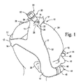
図1および図2を参照すると、本発明の一実施形態によるヘッドギア10が示されている。ヘッドギア10は、中央部14によって互いに一体に接合された、1対の導管または側部12を備える。帯16の形態の頭部取り付け手段もまた、側部12、中央部14および帯16がすべて一体の単体構造体となるよう、図1に示すように側部12と一体に接合される。
Referring to FIGS. 1 and 2, a
側部12、中央部14および帯16は、1対の高分子(たとえばプラスチック)シート17を、たとえば高周波(HF)プラスチック溶接などによって互いに接合することにより形成される。シート17をそれによって互いに接合するやり方は、以下でより詳細に説明するように、側部12の長さに沿って延びる通路を形成するために、シート17の中間部分を互いに分割することができるようなものである。シート17が、そのような通路を側部12の間に形成するように構成される場合、側部12は、導管を構成することが理解され、以下のように述べられる。シート17は、そのような通路を側部12内に形成するのに適した、いかなるやり方で互いに接合することもできる。
The
導管12は、上述したようにシート17の中間部分の分割、したがって通路の形成を容易にするために、シート17が(たとえばプラスチック溶接によって)互いに接合される位置に、内側に延びるプレート(たとえば、導管に対して内側に延びるV字形凹部)を備えることができる。
The
中央部14は、その中心に開口18を有する。ヘッドギア10は、開口18内へと延びるT形結合具またはT形結合装置20を備える。T形結合具20は、1対の側方パイプ22、および側方パイプ22内へと開く中央パイプ24を備える。側方パイプ22は、中央パイプ24が開口18を通って中央部14から突出した状態で、プラスチックシート17の間でそれぞれ反対方向に延びる。側方パイプ22は、側方パイプ22とシート17の間のいくらかの回転運動を可能にしながら、シート17との実質的に気密な封止を形成するように、プラスチックシート17に堅く係合される。
The
側方パイプ22の端部26の位置(図1および図2に破線で示す)はまた、中央部14からそれぞれの側部12への移行を印す働きをする。したがって、側方パイプ22の端部26に対応する導管12の位置は導管12の第1の上端28をなす。
The position of the
その端部に円筒形ユニオン32を有する取り付け構造体またはスイベル30は、中央パイプ24に対して回転可能となるように、中央パイプ24の周りに取り付けられる。以下でさらに説明するように、取り付け構造体30は、空気供給パイプの回転を可能にしながら空気供給パイプを中央パイプ24と流体流動連通させて結合するように、加圧された空気をヘッドギア10へと供給する流れ発生器または空気供給手段(同様に図示せず)から続く空気供給パイプの端部(図示せず)を受けるためのものである。
A mounting structure or swivel 30 having a
図1および図3では、ヘッドギア10は、患者頭部34上に取り付けられて示される。図示のとおり、ヘッドギア10の中央部14およびT形結合具20は、頭部34の頂部36のいくぶん前方部分にて、患者頭部34を横切って延びるように構成され、帯16は、頂部36の後方で頭部34の部分の周りに延びるように構成される。ヘッドギア10は、ヘッドギア10がその上に安定して載るよう、患者頭部34の後頭の湾曲に適合するよう設計される。
In FIGS. 1 and 3, the
また、図1および図3に見られるように、導管12は、患者頭部34の両側で下向きに、患者の目と耳38の間で頭34の各側部上に延びる。導管12は、それらのより低い肢部に向かって前方に曲がって、第1の端部28の反対側の第2の端部40(図1参照)にて終端する。第2の端部40は患者の鼻42に隣接しており、以下(図3参照)で述べるノーズピース150など、患者の鼻に接触する鼻インタフェースに取り付けることができる。
Also, as seen in FIGS. 1 and 3, the
図1に示すように、各導管12の第2の端部40に、鼻取り付け構造体または鼻インタフェース結合装置44が取り付けられ、この鼻取り付け構造体は、それぞれの第2の端部40を通りプラスチックシート17の間で導管12内のある部分(図示せず)および導管12の外側の別の部分46へと延びる部分を有する。
As shown in FIG. 1, a nasal mounting structure or nasal
鼻取り付け構造体44の各部分46は、以下で説明するようにノーズピース150に結合される相補的な構成(図示せず)を受けるためのソケットとして構成される。
Each
図示の実施形態では、シート17は、患者に快適さを提供するためにフロック加工され(たとえばビロード様の質感を有し)、それらの互いに対する取り付けが、縫合部52(図1参照)によって強化される。ヘッドギア10はまた、患者にとって快適となる布またはその他の材料のカバー(図示せず)を備え、カバーは、小児患者にとって魅力的となり得る、たとえば模様またはその他の印などの装飾効果を有することもできる。
In the illustrated embodiment, the
ヘッドギア10の構造的な一体性を向上させるために、あるいはそうではなく、特にたとえば頬骨上など顔の骨領域上での患者への快適さを向上するために、フォームラバーの薄層またはその他の適当な詰物(図示せず)を、シート17の内面の間の選択された位置に設けることができる。
To improve the structural integrity of the
次に図4を参照しながら、ノーズピース150をさらに詳細に説明する。ノーズピース150は、外壁154を有する導管152を備える。外壁154は二重壁であり、内壁部156および外壁部158を有する。内壁部156および外壁部158は、それぞれノーズピース150の第1および第2の端部160,162にて互いに封止接合される。各端部160および162は、それぞれの鼻取り付け構造体44の部分46と流体流動連通して結合されるように構成される。
Next, the
内壁部分156および外壁部分158は、それらの間に、ノーズピース150に関して円周方向に延びる環状空間164を形成する。
導管152は、可撓性プラスチックまたはエラストマー(たとえばシリコーンゴムなど)の別々の鼻腔構造体168を受け入れるための1対の開口166を形成し、鼻腔構造体168は、関連する開口166を貫通して延びる。各鼻腔構造体168は中央通路170を有する。鼻腔構造体168は、患者の鼻42内、すなわち患者の鼻腔内にぴったりと快適に嵌るような形状となる。鼻腔構造体168は、鼻ピロー、鼻プロング、カニューレ、鼻パフなど、いかなる適当な形態を有することもできる。必要に応じて、鼻腔構造体168は、特定の患者の鼻用となるような形状およびサイズとすることができる。
ノーズピース150の外壁154は、導管12の内部と、鼻腔構造体168の通路170、およびしたがって患者の鼻42との間に流体流動連通状態を確立するための中央通路172を形成する。
The
ヘッドギア10と同様、導管152は、図4に示す構造を実現するためにHFプラスチック溶接によって適当に接合することができる、高分子(たとえばプラスチック)材料のシートで形成することができる。
Similar to
図9および図9Aにより詳細に示す一方弁174を有する膨張用ニップル175が、各ノーズピース150の外壁部158を貫通して、それぞれの環状空間164内へと開く。ニップル175および一方弁174によって、導管152にその形状を維持するのに十分な固さを与えるよう導管152を膨張させるように、環状空間164内へと空気を導入することが可能になる。すなわちニップル175および弁174は、導管152の固さまたはサイズを特定の患者または特定の状況に合わせるために調整することが可能になるように、環状空間164へとより多くの空気を導入し、そこから空気を排除するために使用することができる。
An expansion nipple 175 having a one-
ニップル175は短管302を備えることができる。ニップル175は、短管302の下に基部304を備え、基部は、たとえばプラスチック溶接によって、ノーズピース150(またはヘッドギア10が膨張可能である場合はヘッドギア10)と接合される。基部304のプラスチック材料は、管構造体300の残りの部分よりも薄くすることができる。これによって、短管302を、図9の仮想線および矢印305によって表すように、ねじることが可能になる。基部304はまた、以下で説明するように一方弁174の付近にある。
The nipple 175 can include a
ニップル175はまた、短管302を閉じその中を空気が通ることを妨げるための、きついが取り外し可能な嵌合として短管302内で受けることができるキャップ306を備える。図示のように、可撓性のひも308が、キャップ306を短管302の上方側部に接合する。ひも308が可撓性であることによって、キャップ306は、図示のようにそれが短管302を閉じるその閉状態と、それが短管302の開口から取り外される開状態との間で動くことが可能となる。
Nipple 175 also includes a
ニップル175はまた、上方胴領域310、および上方胴領域310より狭い下方胴領域312を備える。これらの胴領域によって、下方胴領域312が上方領域310内部で伸縮式に受けられることを可能にすることによる、ニップル175の変形が可能になる。これによって次に、ニップル175は、それが接合されるノーズピース150(またはヘッドギア10が膨張可能である場合はヘッドギア10)の部分内へと、その部分の内部で反転されるように接合され効果的に詰め込まれるように、押し込まれることが可能になる。
The nipple 175 also includes an
上記のように、ニップル175の基部304は一方弁174の付近にあり、可動フラップ174.1を有する。可動フラップ174.1は短管302の内壁から延び、それにヒンジ結合され、それと一体に形成される。一方弁174は、キャビティ174.5が加圧下にあるときに、フラップ174.1がフランジ174.4を過ぎて矢印174.2の方向に動くことを防止するために戻り止めの目的で働くフランジ174.4を備える。フランジ174.4はまた、フラップ174.1の縁部がそれに接触して封止するための位置を備える。
As described above, the
たとえば、キャビティ174.6が膨張するときなど、キャビティ174.6内部の圧力がキャビティ174.5より大きい場合、フラップ174.1は矢印174.3の方向に動き、膨張が可能になる。圧力差が生じるとすぐにフラップ174.1は閉位置へと動き、一方弁として作用する。ニップル175を通じて収縮させるためには、使用者は、一方弁174の領域の側部を圧迫または圧縮することによってニップル175を変形させるだけでよく、この変形によってフランジ174.4との封が破られ、収縮が可能になる。
For example, when the pressure inside cavity 174.6 is greater than cavity 174.5, such as when cavity 174.6 expands, flap 174.1 moves in the direction of arrow 174.3, allowing expansion. As soon as the pressure difference occurs, the flap 174.1 moves to the closed position and acts as a one-way valve. To contract through the nipple 175, the user only has to deform the nipple 175 by compressing or compressing the side of the area of the one-
別の実施形態では、鼻腔構造体168は剛性プラスチックの別個の構成とするのではなく、導管152と一体にすることができる。そのような実施例では開口166を省略できる。
In another embodiment, the
本実施形態の一形態では、鼻腔構造体168は外壁部および内壁部を有することができ、これらは、それぞれ導管152の外壁部158および内壁部156と連続させることができ、これによって、それらの間に環状空間164と連続させることができる空間を形成する。すなわち導管152の膨張によって、鼻腔構造体168を膨張させることもできる。
In one form of this embodiment, the
図3に示すさらなる実施形態では、ノーズピース150は、ヘッドギア10および導管152が単体構造のものとなるように導管12と一体とすることができる。本実施形態の一形態では、鼻腔構造体168は、導管152の開口166内で受けられる剛性プラスチック構造体とすることができる。本実施形態の別の形態では、鼻腔構造体168は上記のように導管152と一体かつ連続的にすることができる。
In a further embodiment shown in FIG. 3, the
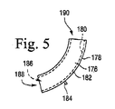
図5に示す別の実施形態では、導管152などの導管、および鼻腔構造体168などの鼻腔構造体を備えるノーズピースを備えるのではなく、2つの膨張可能な湾曲した鼻腔構造体176(1つだけ示す)を備えることができる。図示の実施形態では、各鼻腔構造体176は、中央の取り囲まれた環状空間182を間に形成する外壁部分178および内壁部分180、鼻腔構造体176を膨張させるために空気を空間182内へと導入するための一方弁184、ならびに中央通路186を備える。この実施形態では、各鼻腔構造体176の一端188が、それぞれの鼻取り付け構造体44の部分46に取り付けるように構成され、反対側の端部190が、患者の鼻42内で受けられるように構成される。ある実施形態では、患者の2つの鼻腔のそれぞれのための鼻腔構造体176は、鼻腔構造体176の支持およびそれらの患者の鼻との封止を容易にするために、互いに取り付けられるように構成することができる。
In another embodiment shown in FIG. 5, two inflatable curved nasal structures 176 (one) are provided rather than a nosepiece comprising a conduit, such as
別の実施形態では、ノーズピース150またはその導管152は、上記のような膨張構造以外のものとすることができる。それらは代わりに、導管12と同様の構造の、一重の外壁を有することができる。
In another embodiment, the
たとえば、鼻インタフェースは、参照により本明細書にその全体を組み込む米国特許出願公開第10/781,929号明細書で開示される、鼻アセンブリと同様の構造とすることができる。 For example, the nasal interface can be similar in structure to the nasal assembly disclosed in US patent application Ser. No. 10 / 781,929, which is hereby incorporated by reference in its entirety.
あるいは導管12は、上記のように壁部を一重のプラスチックシートで形成するのではなく、それぞれノーズピース150の内壁部156および外壁部158と同様の内壁部および外壁部を有する二重壁で形成することができる。こうした内壁部および外壁部は、ノーズピース150の空間164と同様の、封止された膨張可能な内部空間を形成する。
Alternatively, the
二重壁のこの構造は、ヘッドギア10の全体、またはその選択された部分に使用することができる。これによって、二重壁であることにより膨張可能であるヘッドギア10の選択された部分を、必要に応じて所望の程度の堅さを実現するために、ノーズピース150の導管152の場合のように膨張させることが可能になる。二重壁構造はまた、壁を通して伝導される騒音を低減させるように働く。
This structure of double walls can be used for the
一実施形態では、そのような二重壁が関連する内壁部と外壁部との間にキャビティを備える場合、上記器具の部品の一部またはすべての内部に内部骨格を設けることができる。内部骨格はまた、たとえばばねワイヤからなることができ、これは、骨格が使用される場合に、さらなる構造的な支持を提供するために拡張状態に構成することができる。 In one embodiment, if such a double wall includes a cavity between the associated inner and outer walls, an internal skeleton can be provided within some or all of the instrument parts. The inner skeleton can also consist of, for example, a spring wire, which can be configured in an expanded state to provide additional structural support when the skeleton is used.
使用に際しては、図1に示すとおり、ヘッドギア10を患者頭部34上に配置することができる。T形結合具20は、加圧下で空気を供給するように構成される、空気供給部(図示せず)の供給パイプ(これも図示せず)に結合される。供給パイプは、T形結合具20との封止を行うために、取り付け構造体30に取り付けるための端部を備える。
In use, the
別の実施形態、または上記実施形態との組み合わせで、供給パイプがヘッドギア10を引く程度を最低限に抑えるために適当な構造を提供することができる。この構造は、T形結合具20への、またはそのようなT形結合装置がない位置実施形態ではそれに相当するヘッドギアの別の部分への、(次段落で説明するような)枢動可能なパイプ結合部、球関節結合部、または可撓性の蛇腹結合部を含むことができる。これによって、供給パイプにかかる抵抗力がヘッドギア10に伝達される程度を低減することにより、ヘッドギア10の安定性を向上させることができる。
In another embodiment, or in combination with the above embodiment, a suitable structure can be provided to minimize the extent to which the supply pipe pulls the
取り付け構造体30は、図10に示すように、円筒形ユニオン32内で終端する蛇腹形の管300を備えることができる。管300によって、空気供給連結部の相対的な回転が可能になり、そうでなければ空気供給結合部を非結合状態にする曲げ力の伝達を妨げることができる。
The mounting
供給された空気は、T形結合具20の中央パイプ24内へと、次いで側方パイプ22を通って導管12へと通過する。空気は陽圧下にあるので、導管12がそれらそれぞれの第1の端部28からそれらそれぞれの第2の端部40へと延びる中央通路を形成するように、導管12を膨張させる働きをする。空気は次いで、鼻取り付け構造体44およびノーズピース150を通り、患者の鼻42(すなわち鼻腔)内へと通過する。
The supplied air passes into the
ヘッドギア10は、特定の患者の頭部34に特別に適合させることができる。これは、頭部34の3次元形状を決定するためにそれを走査またはマッピングし、次いで、シート17が互いに接合されるときに患者頭部34上で密着しかつ快適な適合を実現するのに適したヘッドギア10を形成するよう、シート17を裁断することによって実現することができる。患者頭部34と同様に、多種多様な形状のヘッドギア10があることが理解されるであろう。さらに、特定の患者の頭部に関して、または特定のタイプの頭部形状(2人以上の患者に適合することができる)に関して、シート17をそれによって形成する特定の形状が決定されると、特定のヘッドギアを形成するために特定のシート形状に裁断することができるシートの数は制限されない。
The
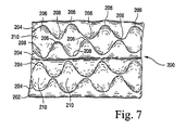
一実施形態では、シート17は、所定の接合経路に沿って接合することができる。これに関しては、経路204に沿って接合される2つのシート202(1つだけ示す)を有する、図7および図8に示すクッション200を参照されたい。経路204は、キルティング様の構成に見ることができるような、山206および谷208を有する正弦曲線状のジグザグ形状のものであることが分かるであろう。各経路204の谷208は、シート202が互いに結合されないほぼダイヤ形の領域210が経路の間に形成されるように、次の経路の山206に位置合せされ、またはその逆となる。説明されているヘッドギア10の一実施形態では、ヘッドギア10は、シート202と同様のやり方で互いに接合されるシート17で形成することができ、経路は、接合されたシート17を頭部34に適合するよう湾曲させる(図8にクッション200の湾曲として表されるように)ことを容易にするための折り曲げ線として働く。
In one embodiment, the
クッション200のダイヤ形領域210に対応するヘッドギア10の領域は、患者にさらなる快適さを提供し、ヘッドギア10を患者頭部34上にしっかりと均等に載せることを容易にするよう、多数の並列されたクッション領域を形成するために膨張させることができる。
The area of the
あるいは、マッピングは、上記のようにシート17の裁断される形状を決定するために用いるのではなく、患者頭部34の形状の熱可塑性重合体を形成することによって、ヘッドギアの一部を形成するために使用することができる。
Alternatively, the mapping forms part of the headgear by forming a thermoplastic polymer in the shape of the
患者頭部34の特定の形状に合うようにヘッドギア10を形状づけることは、患者頭部34にぴったりと適合する、導管12、中央部分14、および帯16を有する、ヘッドギア10の実現を大幅に助ける。これによって、圧力が高い点がそこにある特定の位置と、圧力がそこで不十分である他の位置とを有するのではなく、ヘッドギア10と患者頭部34との間で効果的な圧力分散を実現することができる。これによって、患者頭部34に対する、ヘッドギア10の取り付けを保証することが容易になる。
Shaping the
さらに、ヘッドギア10を特定の患者頭部34に特別に適合させた状態で、導管12、中央部分14、および帯16が単体構造であることによって、そうでなければヘッドギア10を患者頭部34にしっかりと締結するために必要とされるヘッドギアの部品調整が不必要となる。この単体構造によってまた、患者頭部にヘッドギア10をかぶせること、およびそれを取り外すことが簡単になる。
Further, with the
ヘッドギア10を患者頭部34にぴったりと固定することは、上記のような、二重壁、または二重壁を備える部分を有する、ヘッドギア10のこれらの実施形態においてさらに容易にすることができる。いくつかの実施形態では、二重壁の膨張(すなわち二重壁の間の空間内へと膨張空気を提供すること)によって、それぞれの内壁部が、患者頭部34に対して、よりしっかりと押し付けられる。これは特に、患者の耳38のすぐ前など、患者頭部34の実質的に凹状または窪んだ形状の部位に関して有用である。
Tightly fixing the
ノーズピース150を上記のように導管12に接合させた状態で、T形結合具20の中央パイプ24内へと供給される空気は、導管12の通路内を通った後に、ノーズピース150の導管152の通路166に沿って患者の鼻42内へと進む。
With the
患者による呼気は、ある程度気体透過性であり好ましくは患者の鼻42付近にある、プラスチックシート17用の材料を用いることによって促進される。これによって、そこを通る空気および吐き出された二酸化炭素を、ある程度の量漏らしまたは逃がすことが可能になる。適当な熱可塑性エラストマー、たとえばポリオレフィンを、この目的に使用することができる。あるいは、シート17は、完全にプラスチック製とするのではなく、全体的に、たとえば絹またはその他の織物材料などその他のタイプの気体透過性材料製、またはGORETEX(登録商標)として知られるポリテトラフルオロエチレン(PTFE)材料製とし、またはこれらの材料製の部分を有することができる。
Breathing by the patient is facilitated by using a material for the
患者が息を吐くとき、呼気は次いで、ノーズピース150内を通過し、その第2の端部40に近い位置にて、導管12の壁部を通る。
As the patient exhales, exhalation then passes through the
シートに特に適した材料は、外に逃げる空気と共に水蒸気の通過を可能にするが、実質的に気密な通路を形成する、通気性ポリウレタンとすることができる。「実質的に気密」という表現は、外に逃げる空気が多くなり過ぎることを防ぐために、そこを通る空気の通過への十分な抵抗が提供されることを意味する。水蒸気の通過を可能にする能力は、患者によって吐き出される気体からの水分の、導管12の内部通路内での望ましくない凝集を避けることを助けるので、有利である。これらの特性を提供することができる材料は、Darlington Corporation社によって製造される商標DARLEXX(登録商標)によって知られるもの、または商標THINSLATE(登録商標)によって知られる3M社の製品、またはGORETEX(登録商標)として知られるポリテトラフルオロエチレン(PTFE)材料、または、Atlantis Weather Gear Inc社によって製造されるATLANTECH(商標)として知られる製品を含む。
A particularly suitable material for the sheet can be a breathable polyurethane that allows the passage of water vapor with the air escaping outside, but forms a substantially airtight passage. The expression “substantially airtight” means that sufficient resistance to the passage of air therethrough is provided to prevent too much air escaping outside. The ability to allow the passage of water vapor is advantageous because it helps to avoid undesired aggregation of moisture from the gas exhaled by the patient in the internal passages of the
導管12の壁部またはその部分が上記のように気体透過性である状態では、T結合部20の中央パイプ24を通って供給される空気のいくらかは導管12からも逃げる。この構成、および通路の可撓性である性質は、導管12を通るノーズピース150への空気の通過によって発生する雑音の低減を助けることができる。
Some of the air supplied through the
導管12の壁部を通る呼気の通過はまた、熱をヘッドギア10から逃がすことを可能にするための有用な手段となる。そのような熱をこのようにして逃がすことができない場合、ヘッドギア10は結果的に、無用に、患者にとって不快感となるほど加熱されることがある。さらに、特により暖かい気候において快適さを向上させるために、使用される材料の上記のような気体透過性によって、患者頭部34の頂部上にあるヘッドギアの部品内を通る熱および水蒸気の通過を可能にすることができる。ヘッドギア10の構造、および特にその単体であるという性質は、患者がヘッドギア10を装着し、彼らの頭部34を枕などの表面上に転がし、そのため導管12の一方が枕の上の患者頭部34の圧力によって平坦になる場合に、その導管12内を通過するはずであったが導管の通路が狭まることにより通過が妨げられる空気のすべてまたはほとんどが、代わりにもう一方の導管12内を通過することを可能にするという利点を有する。これは、導管12の可撓性、および結果的に生じるその拡張し実質的につぶれる能力により可能になる。すなわち、導管の対を通る空気の総体積流量は、それぞれの導管が平坦になるときおよび拡張するときにほぼ一定に維持される。上記の平坦化および拡張が生じる際の導管12の構成および断面形状に応じて、導管12のつぶれによって、その導管の高さ方向の長さおよび横方向長さの間の比に変化が生じ、高さ方向長さが減少し横方向長さが増大する。同様に、もう一方の導管の変形によって、その導管の高さ方向の長さおよび横方向長さの間の比に変化が生じ、高さ方向長さが増大し横方向長さが減少する。
The passage of exhaled air through the wall of the
一実施形態では、ヘッドギアは、調整可能な頭部キャップを備えることができ、複数の導管がキャップの両側でそれに取り付けられる。この場合、キャップは、取り付け手段を構成することができ、結合手段を、キャップ上に取り付けることができる。 In one embodiment, the headgear can comprise an adjustable head cap, with a plurality of conduits attached to it on both sides of the cap. In this case, the cap can constitute an attachment means and the coupling means can be attached on the cap.
別の実施形態では、導管は、取り付け手段をさまざまなサイズおよび/または形状の導管に選択的に解放可能に結合することができるように、取り外し手段から取り外し可能とすることができる。この場合、導管は、さまざまなサイズおよび形状の取り付け手段に選択的に解放可能に結合することができ、それによってヘッドギアは、相互交換可能な取り付け手段および導管を有するモジュール式ヘッドギアシステムの一部を形成することができる。 In another embodiment, the conduit can be removable from the removal means so that the attachment means can be selectively releasably coupled to conduits of various sizes and / or shapes. In this case, the conduit can be selectively releasably coupled to attachment means of various sizes and shapes so that the headgear can be part of a modular headgear system having interchangeable attachment means and conduits. Can be formed.
さらに別の実施形態では、ヘッドギアは、患者のマスクと共に使用することができるよう構成することができ、マスクは、気体を導管から鼻へと送るよう、患者の鼻に隣接する患者頭部に適合するように構成することができる。次いで、ヘッドギアは、患者がヘッドギアを着用し続けながら、マスクをヘッドギアから、したがって患者頭部から選択的に取り外すことが可能になるように、マスクから取り外し可能となるよう構成することができる。 In yet another embodiment, the headgear can be configured for use with a patient's mask, and the mask is adapted to the patient's head adjacent to the patient's nose to deliver gas from the conduit to the nose. Can be configured to. The headgear can then be configured to be removable from the mask so that the patient can be selectively removed from the headgear and thus from the patient's head while the patient continues to wear the headgear.
上記のようなヘッドギア10の具体的な利点は、非使用時に、T形結合具20を開口18から取り外すことができることである。次いで、導管12、中央部分14および帯16は、導管12の通路をつぶすように平坦にすることができ、必要とされる保管用空間が最小限となるように、保管目的で巻上げ、または折り畳むことができる。一方、使用時は、導管12内を空気が通過すること自体が、通路を膨張させ、快適なかつぴったりとした適合が実現されるように導管12の内壁を患者頭部34の側部に対してしっかりと押し付ける働きをする。
A specific advantage of the
ヘッドギア10はさまざまな利点を有する。たとえば、ヘッドギア10の1つの利点は、T形結合部20が、使用時に、たとえば患者頭部が枕の上にあることなどによる、いかなる圧縮力も受けにくい、患者頭部の一部分に配置されることである。すなわち、導管12は可撓性であり、したがって、患者がそれらの上に載る場合さえ不快感があまりもたらされないはずであるが、これはこの構成要素の配置により、比較的硬いT形結合具20に関しては問題とはならないはずである。
The
さらに、導管12、中央位置14および帯16がそれから形成される材料が、比較的可撓性のものでありしたがって柔らかいことにより、従来技術の装置を係合させるには敏感過ぎることがあった患者の頬など患者の頭部部位に、ヘッドギア10を係合させることが可能になる。
In addition, patients from whom the
導管12および中央部分14が、空気がそれを通って患者に送達されるように移動する必要があるほとんどの通路を形成するという事実は、追加の管機構および管機構固定用帯の必要性を回避することができることを意味する。したがって、これによって、そのような追加の管機構および固定用帯に伴う可能性があるかさおよび重量もなくなる。
The fact that the
一方の導管12が、患者の顔に接触してほぼ平坦となるように圧迫されるかまたはつぶされる場合(たとえば患者が枕の上で一方の導管12に載る場合など)に、より大きい体積流量が可能になるように拡張するもう一方の導管12の能力によって、患者の快適さが向上し、より可撓性の低い管機構が使用された場合に生じる可能性のある不快感が最低限に抑えられる。これによってまた、ヘッドギア10が患者頭部34上の接触圧点に係合することによって生じることがある不快感が低減される。
Greater volumetric flow when one
ヘッドギア10を製造するために上記のプラスチック溶接を使用することによって、クリップ、バックル、調整帯などの必要がなくなり、使用が大幅に単純になる。さらに、患者頭部34の形状、およびヘッドギア10固有の軽量であるという性質に合うようにヘッドギア10を形成することは、患者に対する快適さをより高めることを助ける。
By using the above-described plastic welding to manufacture the
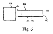
図6を参照すると、本発明の一実施形態によるPAP装置の導管400を表す概略図が示されている。導管400は、可撓性の導管壁402、ならびに第1の端部404および第2の端部406を有する。第1の端部404は、陽圧下で空気を供給するための供給手段408に取り付けられる。上記導管12の場合のように、導管400はつぶれることができる。供給手段408によって陽圧下の空気が供給されるとき、空気の圧力によって壁402が図示の状態になり、その状態で壁402は、導管400の中央通路410を形成する。すなわち、空気は通路410に沿って第2の端部406へと通過させることができ、そこで必要に応じて方向付けることができる。
Referring to FIG. 6, a schematic diagram illustrating a
壁402を空気の圧力のみによって図示の状態にする代わりに、使用時に導管400のねじれを防止することを助ける、伸縮可能なばねを設けることができる。
Instead of bringing the
壁402が可撓性であることによって、導管400を、保管または移動時に小型サイズにするために折り畳みまたは丸めることが可能になる。さらに、これらの壁は、上記の壁154と同様に、一重壁タイプまたは二重壁タイプとすることができる。そのような二重壁構造によってまた、空気供給手段408からの空気の温度制御を助けるために、断熱性を高めることができる。
The flexibility of the
図11にヘッドギア1010を示すが、これは、図1および図2のヘッドギア10と同様であり、したがって同様の部品は同様の番号で示した。ヘッドギア1010は、ヘッドギア10のそれぞれの導管または側部12にそれぞれ結合されそこから延びる2つの帯1012が設けられている点でヘッドギア10と異なる。帯1012は、マスクまたはノーズピースに結合させることができ使用者がヘッドギア1010を彼らの頭に固定することを可能にする、バックル部材1014および1016内でそれぞれ終端する。帯1012は、その長さを調整可能にすることができる。
FIG. 11 shows a
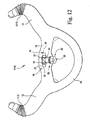
図12にヘッドギア1110を示すが、これは図1および図2のヘッドギア10と同様であり、したがって同様の部品は同様の番号で示した。ヘッドギア1110は、各導管または側部12の端部上に伸縮可能なカフ1112が設けられるという点で、ヘッドギア10と異なる。図示のように、伸縮可能なカフ1112は蛇腹構成である。伸縮可能なカフ1112は、必要に応じて伸張しまたは収縮することによって、導管12の端部の長さを調整することを可能にする。
FIG. 12 shows a
本明細書で開示および規定される発明が、本文で述べられまたは明らかになる個々の特徴の、2つ以上の代替の組合せのすべてに及ぶことが理解されるであろう。これらの異なる組み合わせはすべて本発明のさまざまな代替態様を構成する。 It will be understood that the invention disclosed and defined herein extends to all two or more alternative combinations of individual features described or apparent herein. All of these different combinations constitute various alternative aspects of the invention.
本発明を、現在最も実用的かつ好ましい実施形態であると考えられるものに関連付けて説明してきたが、本発明は、開示された実施形態に限定されるべきではなく、反対に、本発明の精神および範囲に包含されるさまざまな修正および同等の構成を網羅することが意図されることを理解されたい。さらに、本発明はOSAを患う患者への特定の応用例を有するが、その他の疾患を患う患者(たとえば、うっ血性心不全、糖尿病、病的肥満、卒中、肥満外科手術など)が、上記の教示から利益を導くことができることが理解されるべきである。さらに、上記教示は患者および非患者への適用性を同様に有する。 Although the present invention has been described in connection with what is presently considered to be the most practical and preferred embodiments, the present invention should not be limited to the disclosed embodiments, but on the contrary. It should be understood that the various modifications and equivalent arrangements encompassed within the scope and range are intended to be covered. Further, while the present invention has particular application to patients with OSA, patients with other diseases (e.g. congestive heart failure, diabetes, morbid obesity, stroke, bariatric surgery, etc.) It should be understood that profits can be derived from. Furthermore, the above teachings have patient and non-patient applicability as well.
10 ヘッドギア
12 導管(側部)
14 中央部
16 帯
17 プラスチックシート
18 開口
20 T形結合具
22 側方パイプ
24 中央パイプ
26 端部
28 第1の上端
30 取り付け構造体(スイベル)
32 円筒形ユニオン
34 患者頭部
36 頂部
38 耳
40 第2の端部
42 鼻
44 鼻取り付け構造体(鼻インタフェース結合装置)
46 別の部分
52 縫合部
150 ノーズピース
152 導管
154 外壁
156 内壁部
158 外壁部
160 第1の端部
162 第2の端部
164 環状空間
166 開口
168 鼻腔構造体
170,172 中央通路
174 一方弁
174.1 可動フラップ
174.4 フランジ
174.5,174.6 キャビティ
175 膨張用ニップル
176 鼻腔構造体
178 外壁部分
180 内壁部分
182 環状空間
184 一方弁
186 中央通路
188 一端
190 端部
202 シート
204 経路
206 山
208 谷
210 ダイヤ形の領域
300 管構造体
302 短管
304 基部
306 キャップ
308 ひも
310 上方胴領域
312 下方胴領域
400 導管
402 導管壁
404 第1の端部
406 第2の端部
408 供給手段
410 中央通路
1010 ヘッドギア
1012 帯
1014,1016 バックル部材
1112 カフ
10 Headgear
12 Conduit (side)
14 Center
16 bands
17 Plastic sheet
18 opening
20 T-joint
22 Side pipe
24 center pipe
26 edge
28 First top edge
30 Mounting structure (swivel)
32 Cylindrical union
34 Patient head
36 Top
38 Ear
40 Second end
42 nose
44 Nasal mounting structure (nasal interface coupling device)
46 Another part
52 sutures
150 Nosepiece
152 conduit
154 Exterior wall
156 Inner wall
158 Exterior wall
160 First end
162 Second end
164 Annular space
166 opening
168 Nasal structure
170,172 Central passage
174 One-way valve
174.1 Movable flap
174.4 Flange
174.5, 174.6 Cavity
175 Expansion nipple
176 Nasal structure
178 Exterior wall
180 inner wall
182 Annular space
184 One-way valve
186 Central passage
188 one end
190 edge
202 seats
204 routes
206 mountains
208 valley
210 Diamond-shaped area
300 pipe structure
302 short pipe
304 base
306 cap
308 thong
310 Upper trunk area
312 Lower trunk area
400 conduits
402 conduit wall
404 first end
406 Second end
408 Supply means
410 Central passage
1010 headgear
1012 belt
1014,1016 Buckle member
1112 cuff
Claims (54)
第1の導管端部(28,404)と第2の導管端部(40,406)とを有する導管壁(402)を備え、前記第1の導管端部(28,404)が、気体供給部(408)に取り付けられるようになされ、
前記導管壁(402)は、
(a)前記導管壁(402)が導管通路(410)を形成し、それに沿って前記供給気体が前記第1の導管端部(28,404)から前記第2の導管端部(40,406)までの間で移動することができる開いた状態と、
(b)前記導管壁(402)が前記導管通路(410)を実質的につぶす、つぶれた状態との間で変形可能であることを特徴とする導管。 A conduit (12,152,400) for delivering a feed gas (408) under positive pressure,
A conduit wall (402) having a first conduit end (28,404) and a second conduit end (40,406), wherein the first conduit end (28,404) is attached to a gas supply (408) Was made possible,
The conduit wall (402)
(a) the conduit wall (402) forms a conduit passageway (410) along which the feed gas extends from the first conduit end (28,404) to the second conduit end (40,406). In the open state, which can be moved with,
(b) A conduit characterized in that the conduit wall (402) is deformable between a collapsed state and substantially collapses the conduit passageway (410).
気体供給部に取り付けるようになされた結合装置(20)と、
前記結合装置(20)に取り付けられた第1の導管端部(28)および前記患者の鼻に隣接して配置されるようになされた第2の導管端部(40)を有する導管を形成する、前記患者頭部の両側に沿って延びるようになされた1対の側部(12)と、
前記ヘッドギアを前記患者頭部に取り外し可能に固定するようになされた頭部取り付け構造体(16)と、を備えることを特徴とするヘッドギア。 A headgear (10) for delivering a supply gas under positive pressure to a patient,
A coupling device (20) adapted to be attached to a gas supply;
Forming a conduit having a first conduit end (28) attached to the coupling device (20) and a second conduit end (40) adapted to be positioned adjacent to the patient's nose. A pair of sides (12) adapted to extend along opposite sides of the patient's head;
A headgear structure comprising: a head mounting structure (16) adapted to removably fix the headgear to the patient's head.
(a)前記導管が導管通路を形成し、それに沿って前記供給気体が前記第1の導管端部から前記第2の端部までの間を移動することができる開いた状態と、
(b)前記導管が前記導管通路を実質的につぶす、つぶれた状態との間で変形可能であることを特徴とする請求項9に記載のヘッドギア。 The conduit is
(a) an open state in which the conduit forms a conduit passage along which the feed gas can travel from the first conduit end to the second end;
10. The headgear according to claim 9, wherein (b) the conduit is deformable between a collapsed state and substantially collapses the conduit passage.
気体供給部に取り付けられるようになされた結合装置(20)と、
前記患者の鼻に係合するようになされたノーズピース(150)と、
前記結合装置に取り付けられた第1の導管端部(28)および前記ノーズピース(150)に結合させるようになされた第2の導管端部(40)を有する導管をそれぞれ形成する、前記患者頭部の両側に沿って延びるようになされた1対の側部(12)と、
前記ヘッドギアを前記患者頭部に取り外し可能に固定するようになされた頭部取り付け構造体(16)と、を備えることを特徴とする鼻用アセンブリ。 A nasal assembly for delivering a supply gas under positive pressure to a patient comprising:
A coupling device (20) adapted to be attached to a gas supply;
A nosepiece (150) adapted to engage the patient's nose;
The patient head, each forming a conduit having a first conduit end (28) attached to the coupling device and a second conduit end (40) adapted to couple to the nosepiece (150). A pair of sides (12) adapted to extend along both sides of the part;
A nasal assembly comprising: a head mounting structure (16) adapted to removably secure the headgear to the patient's head.
(a)前記導管が導管通路を形成し、それに沿って前記供給気体が前記第1の導管端部から前記第2の端部までの間を移動することができる開いた状態と、
(b)前記導管が前記導管通路を実質的につぶす、つぶれた状態との間で変形可能であることを特徴とする請求項26に記載の鼻用アセンブリ。 The conduit is
(a) an open state in which the conduit forms a conduit passage along which the feed gas can travel from the first conduit end to the second end;
27. The nasal assembly according to claim 26, wherein (b) the conduit is deformable between a collapsed state that substantially collapses the conduit passage.
(a)前記導管が導管通路を形成し、それに沿って前記供給気体が前記第1の導管端部から前記第2の端部までの間を移動することができる開いた状態と、
(b)前記導管が前記導管通路を実質的につぶす、つぶれた状態との間で変形可能であることを特徴とする請求項26または請求項27に記載の鼻用アセンブリ。 The nosepiece comprises a conduit, the conduit comprising:
(a) an open state in which the conduit forms a conduit passage along which the feed gas can travel from the first conduit end to the second end;
28. A nasal assembly according to claim 26 or claim 27, wherein the conduit is deformable between a collapsed state, wherein the conduit substantially collapses the conduit passage.
第1の導管端部(28,404)と第2の導管端部(40,406)とを有する導管壁(402)を備える導管(12,152,400)を設けることであって、前記導管壁(402)が、
(a)前記導管壁(402)が導管通路(410)を形成し、それに沿って前記供給気体が前記第1の導管端部(28,404)から前記第2の導管端部(40,406)までの間で移動することができる開いた状態と、
(b)前記導管壁(402)が前記導管通路(410)を実質的につぶす、つぶれた状態との間で変形可能である導管を設けることと、
前記導管(12,152,400)の前記第1の導管端部(28,404)を前記気体供給部に結合させることと、
前記供給気体が前記第1の導管端部(28,404)から前記第2の導管端部(40,406)へと移動することを可能にするために、前記供給気体によって前記導管壁(402)が前記開いた状態とされるように、前記供給気体を、前記第1の導管端部(28,404)を通して前記導管(12,152,400)内へと送達することとを含むことを特徴とする方法。 In a method for using a conduit to deliver a feed gas under positive pressure,
Providing a conduit (12,152,400) comprising a conduit wall (402) having a first conduit end (28,404) and a second conduit end (40,406), the conduit wall (402) comprising:
(a) the conduit wall (402) forms a conduit passageway (410) along which the feed gas extends from the first conduit end (28,404) to the second conduit end (40,406). In the open state, which can be moved with,
(b) providing a conduit that is deformable between a collapsed state, wherein the conduit wall (402) substantially collapses the conduit passageway (410);
Coupling the first conduit end (28,404) of the conduit (12,152,400) to the gas supply;
The supply gas opens the conduit wall (402) to allow the supply gas to move from the first conduit end (28,404) to the second conduit end (40,406). Delivering the supply gas through the first conduit end (28,404) and into the conduit (12,152,400) so as to be in a closed state.
前記供給気体がそれに沿って移動することができる導管通路を形成する、少なくとも1つの導管(12)を備えるヘッドギア(10)を提供することと、
特定の患者の頭部形状をマッピングすることと、
前記マッピングに従って、前記ヘッドギア(10)が、前記特定の患者の頭部上に実質的に密着しかつ快適に嵌ることが実現されるように、前記ヘッドギア(10)をヘッドギア形状に形成することとを含むことを特徴とする方法。 A method for configuring a headgear to deliver a supply gas under positive pressure to a patient comprising:
Providing a headgear (10) comprising at least one conduit (12) forming a conduit passage through which the supply gas can travel;
Mapping a specific patient's head shape;
Forming the headgear (10) in a headgear shape so that the headgear (10) is substantially fit and comfortably fit on the head of the particular patient according to the mapping; A method comprising the steps of:
Applications Claiming Priority (2)
| Application Number | Priority Date | Filing Date | Title |
|---|---|---|---|
| AU2004902020A AU2004902020A0 (en) | 2004-04-15 | Improved Pap Conduit | |
| PCT/AU2005/000539 WO2005099801A1 (en) | 2004-04-15 | 2005-04-15 | Positive-air-pressure machine conduit |
Related Child Applications (2)
| Application Number | Title | Priority Date | Filing Date |
|---|---|---|---|
| JP2011047484A Division JP2011115608A (en) | 2004-04-15 | 2011-03-04 | Positive pressure breathing device conduit |
| JP2012009839A Division JP5753801B2 (en) | 2004-04-15 | 2012-01-20 | Positive pressure breathing device conduit |
Publications (2)
| Publication Number | Publication Date |
|---|---|
| JP2007532205A true JP2007532205A (en) | 2007-11-15 |
| JP2007532205A5 JP2007532205A5 (en) | 2010-03-11 |
Family
ID=35149792
Family Applications (3)
| Application Number | Title | Priority Date | Filing Date |
|---|---|---|---|
| JP2007507626A Withdrawn JP2007532205A (en) | 2004-04-15 | 2005-04-15 | Positive pressure breathing device conduit |
| JP2011047484A Pending JP2011115608A (en) | 2004-04-15 | 2011-03-04 | Positive pressure breathing device conduit |
| JP2012009839A Expired - Fee Related JP5753801B2 (en) | 2004-04-15 | 2012-01-20 | Positive pressure breathing device conduit |
Family Applications After (2)
| Application Number | Title | Priority Date | Filing Date |
|---|---|---|---|
| JP2011047484A Pending JP2011115608A (en) | 2004-04-15 | 2011-03-04 | Positive pressure breathing device conduit |
| JP2012009839A Expired - Fee Related JP5753801B2 (en) | 2004-04-15 | 2012-01-20 | Positive pressure breathing device conduit |
Country Status (6)
| Country | Link |
|---|---|
| US (11) | US20070246043A1 (en) |
| EP (1) | EP1740247B1 (en) |
| JP (3) | JP2007532205A (en) |
| CN (1) | CN1942215B (en) |
| NZ (3) | NZ595133A (en) |
| WO (1) | WO2005099801A1 (en) |
Cited By (5)
| Publication number | Priority date | Publication date | Assignee | Title |
|---|---|---|---|---|
| JP2015517870A (en) * | 2012-06-01 | 2015-06-25 | コーニンクレッカ フィリップス エヌ ヴェ | Respiratory interface device that supplies gas to the user |
| JP2018138231A (en) * | 2006-07-28 | 2018-09-06 | レスメド・リミテッドResMed Limited | Delivery of respiratory therapy |
| US11020558B2 (en) | 2006-07-28 | 2021-06-01 | ResMed Pty Ltd | Delivery of respiratory therapy |
| US11376384B2 (en) | 2006-07-28 | 2022-07-05 | ResMed Pty Ltd | Delivery of respiratory therapy using conduits with varying wall thicknesses |
| US11446461B2 (en) | 2006-12-15 | 2022-09-20 | ResMed Pty Ltd | Delivery of respiratory therapy |
Families Citing this family (92)
| Publication number | Priority date | Publication date | Assignee | Title |
|---|---|---|---|---|
| NZ573196A (en) | 2002-09-06 | 2010-07-30 | Resmed Ltd | Cushion for a respiratory mask assembly with two force applying features for respectively low and high mask pressure |
| EP2574360B1 (en) | 2002-11-06 | 2021-02-24 | ResMed Pty Ltd | Mask and components thereof |
| NZ562414A (en) | 2003-02-21 | 2009-02-28 | Resmed Ltd | Headgear assembly for nasal pillow mask |
| NZ732925A (en) | 2003-12-31 | 2019-01-25 | ResMed Pty Ltd | Compact oronasal patient interface |
| WO2005099801A1 (en) | 2004-04-15 | 2005-10-27 | Resmed Limited | Positive-air-pressure machine conduit |
| US8807135B2 (en) | 2004-06-03 | 2014-08-19 | Resmed Limited | Cushion for a patient interface |
| EP2705870B1 (en) | 2005-01-12 | 2019-11-13 | ResMed Pty Ltd | Cushion for patient interface |
| US8701668B2 (en) | 2005-10-14 | 2014-04-22 | Resmed Limited | Nasal assembly |
| WO2007041751A1 (en) | 2005-10-14 | 2007-04-19 | Resmed Limited | Cushion to frame assembly mechanism |
| US20090126739A1 (en) | 2005-10-25 | 2009-05-21 | Resmed Limited | Interchangeable Mask Assembly |
| US7578294B2 (en) | 2005-12-02 | 2009-08-25 | Allegiance Corporation | Nasal continuous positive airway pressure device and system |
| US20080142015A1 (en) * | 2006-01-27 | 2008-06-19 | David Groll | Apparatus to provide continuous positive airway pressure |
| FI118724B (en) * | 2006-04-20 | 2008-02-29 | Euromaski Oy | Protective device |
| AU2014201200B2 (en) * | 2006-07-28 | 2015-08-27 | Resmed Limited | Delivery of Respiratory Therapy |
| EP3871721A1 (en) * | 2006-10-24 | 2021-09-01 | ResMed Motor Technologies Inc | Brushless dc motor with bearings |
| CN103418070B (en) * | 2006-12-15 | 2017-03-01 | 瑞思迈有限公司 | Delivery of respiratory therapy |
| US8517023B2 (en) | 2007-01-30 | 2013-08-27 | Resmed Limited | Mask system with interchangeable headgear connectors |
| NZ589685A (en) | 2007-04-19 | 2012-06-29 | Resmed Ltd | Cushion for patient breathing interface with variable density foam supported membrane |
| NZ754622A (en) | 2007-07-30 | 2021-02-26 | ResMed Pty Ltd | Patient interface |
| US8397727B2 (en) * | 2007-08-24 | 2013-03-19 | Resmed Limited | Mask vent |
| US9308343B2 (en) | 2008-02-19 | 2016-04-12 | Circadiance, Llc | Respiratory mask with disposable cloth body |
| US9981104B1 (en) | 2008-02-19 | 2018-05-29 | Circadiance, Llc | Full face cloth respiratory mask |
| EP2259827B1 (en) | 2008-03-04 | 2019-10-30 | ResMed Pty Ltd | A foam respiratory mask |
| DE202009018972U1 (en) | 2008-03-04 | 2014-12-09 | Resmed Limited | mask system |
| CN104721937A (en) | 2008-03-04 | 2015-06-24 | 瑞思迈有限公司 | Interface including a foam cushioning element |
| US11331447B2 (en) | 2008-03-04 | 2022-05-17 | ResMed Pty Ltd | Mask system with snap-fit shroud |
| US8905031B2 (en) | 2008-06-04 | 2014-12-09 | Resmed Limited | Patient interface systems |
| CN106039505A (en) | 2008-06-04 | 2016-10-26 | 瑞思迈有限公司 | Patient interface systems |
| AU2009291491C1 (en) | 2008-09-12 | 2016-04-21 | ResMed Pty Ltd | A foam-based interfacing structure method and apparatus |
| EP2334360B1 (en) * | 2008-10-17 | 2016-12-14 | Koninklijke Philips N.V. | Inlet airflow assembly in a medical ventilator |
| EP2213324B1 (en) | 2009-01-30 | 2016-07-27 | ResMed R&D Germany GmbH | Patient interface structure and method/tool for manufacturing same |
| US8783298B2 (en) * | 2009-07-29 | 2014-07-22 | Kast Silicone Ltd. | Breathing hose |
| CA3106017A1 (en) * | 2009-12-22 | 2011-06-30 | Fisher & Paykel Healthcare Limited | Components for medical circuits |
| CN102725018A (en) * | 2010-01-15 | 2012-10-10 | 皇家飞利浦电子股份有限公司 | Replaceable nasal pillow |
| WO2011091503A1 (en) * | 2010-01-29 | 2011-08-04 | Len Erickson | Headpiece with passage for air and like gases |
| EP3427784B1 (en) | 2010-09-01 | 2022-08-24 | ResMed Pty Ltd | Mask system |
| US8567400B2 (en) | 2010-10-05 | 2013-10-29 | Carefusion 207, Inc. | Non-invasive breathing assistance device with flow director |
| US8607794B2 (en) | 2010-10-05 | 2013-12-17 | Carefusion 207, Inc. | Non-invasive breathing assistance apparatus and method |
| US20150128949A1 (en) * | 2011-02-11 | 2015-05-14 | Koninklijke Philips | Patient interface device having headgear providing integrated gas flow and delivery |
| DE112012007300B4 (en) | 2011-04-15 | 2024-04-25 | Fisher & Paykel Healthcare Ltd. | Interface with a movable nose bridge |
| US10603456B2 (en) | 2011-04-15 | 2020-03-31 | Fisher & Paykel Healthcare Limited | Interface comprising a nasal sealing portion |
| WO2012167327A1 (en) * | 2011-06-08 | 2012-12-13 | Resmed Limited | Air delivery conduit |
| NZ621617A (en) | 2011-08-22 | 2016-02-26 | Resmed Ltd | Manufactured to shape headgear and masks |
| MY170569A (en) * | 2011-08-22 | 2019-08-19 | ResMed Pty Ltd | Ultrasonic welding of fabrics for sleep apnea treatment |
| EP2744554B1 (en) * | 2011-10-27 | 2019-12-11 | Koninklijke Philips N.V. | Collapsible breathing gas conduit for a respiratory therapy system |
| AU2012334808B2 (en) | 2011-11-08 | 2015-10-01 | ResMed Pty Ltd | Electrically stimulated respiratory assistance components |
| WO2013076624A1 (en) * | 2011-11-22 | 2013-05-30 | Koninklijke Philips Electronics N.V. | Inflatable headgear for a patient interface assembly |
| US9872966B2 (en) * | 2012-04-17 | 2018-01-23 | Koninklijke Philips N.V. | Gas delivery conduit for a respiratory therapy system |
| JP6276752B2 (en) * | 2012-04-20 | 2018-02-07 | コーニンクレッカ フィリップス エヌ ヴェKoninklijke Philips N.V. | Gas carrying headgear with porous boundary membrane |
| WO2014020473A2 (en) * | 2012-08-03 | 2014-02-06 | Koninklijke Philips N.V. | Headgearless patient interface assembly |
| EP2892596B1 (en) | 2012-09-04 | 2023-07-26 | Fisher&Paykel Healthcare Limited | Valsalva mask |
| US9032959B2 (en) * | 2012-12-04 | 2015-05-19 | Ino Therapeutics Llc | Cannula for minimizing dilution of dosing during nitric oxide delivery |
| JP6336575B2 (en) | 2013-04-26 | 2018-06-06 | フィッシャー アンド ペイケル ヘルスケア リミテッド | Respirator headgear |
| US9517318B2 (en) | 2013-06-28 | 2016-12-13 | L'Air Liquide, Société Anonyme pour l'Etude et l'Exploitation des Procédés Georges Claude | Method of delivering medical gases via a nasal cannula assembly with flow control passage communicating with a deformable reservoir |
| US9566407B2 (en) | 2013-06-28 | 2017-02-14 | L'Air Liquide, Société Anonyme pour l'Etude et l'Exploitation des Procédés Georges Claude | Nasal cannula assembly with flow control passage communicating with a deformable reservoir |
| US9486600B2 (en) | 2013-06-28 | 2016-11-08 | L'Air Liquide, Société Anonyme pour l'Etude et l'Exploitation des Procédés Georges Claude | Nasal cannula assembly with inhalation valves communicating with a deformable reservoir |
| US9492626B2 (en) * | 2013-06-28 | 2016-11-15 | L'Air Liquide, Société Anonyme pour l'Etude et l'Exploitation des Procédés Georges Claude | Breathing assistance assemblies suitable for long term no therapy |
| US9522247B2 (en) | 2013-06-28 | 2016-12-20 | L'Air Liquide, Société Anonyme pour l'Etude et l'Exploitation des Procédés Georges Claude | Method of treating a patient having pulmonary hypertension by long term NO therapy |
| US9522248B2 (en) | 2013-06-28 | 2016-12-20 | L'Air Liquide, Société Anonyme pour l'Etude et l'Exploitation des Procédés Georges Claude | Breathing assistance apparatus for delivery of nitric oxide to a patient by means of a nasal cannula assembly with flow control passage |
| CA2919449C (en) | 2013-08-05 | 2022-04-12 | Fisher & Paykel Healthcare Limited | Seal for a patient interface, interface assemblies and aspects thereof |
| EP3838324B1 (en) | 2014-06-17 | 2023-07-26 | Fisher & Paykel Healthcare Limited | Patient interfaces |
| ES2748330T3 (en) * | 2014-07-16 | 2020-03-16 | Breas Medical Inc | Adjustable positive airway pressure or ventilation system |
| US20160346496A1 (en) * | 2014-07-16 | 2016-12-01 | Human Design Medical, Llc | Facial interface and headgear system for use with ventilation and positive air pressure systems |
| GB2587307B (en) | 2014-08-25 | 2021-10-27 | Fisher & Paykel Healthcare Ltd | Respiratory mask and related portions, components or sub-assemblies |
| SG11201703928QA (en) | 2014-11-14 | 2017-06-29 | Fisher & Paykel Healthcare Ltd | Patient interface |
| WO2016085464A1 (en) * | 2014-11-25 | 2016-06-02 | Accumed Innovative Technologies, Llc | Head gear assembly and method |
| SG10201909092SA (en) | 2015-03-31 | 2019-11-28 | Fisher & Paykel Healthcare Ltd | A user interface and system for supplying gases to an airway |
| EP3405244B1 (en) * | 2016-01-21 | 2021-11-03 | ResMed Pty Ltd | Adjustable headgear tubing for a patient interface |
| CA3033581A1 (en) | 2016-08-11 | 2018-02-15 | Fisher & Paykel Healthcare Limited | A collapsible conduit, patient interface and headgear connector |
| USD823455S1 (en) | 2017-02-23 | 2018-07-17 | Fisher & Paykel Healthcare Limited | Cushion assembly for breathing mask assembly |
| USD824020S1 (en) | 2017-02-23 | 2018-07-24 | Fisher & Paykel Healthcare Limited | Cushion assembly for breathing mask assembly |
| USD823454S1 (en) | 2017-02-23 | 2018-07-17 | Fisher & Paykel Healthcare Limited | Cushion assembly for breathing mask assembly |
| US20180250487A1 (en) * | 2017-03-06 | 2018-09-06 | Susan Hodges | CPAP Mask Connector and Pillow System |
| CN111163825A (en) * | 2017-09-28 | 2020-05-15 | 皇家飞利浦有限公司 | Inflatable catheter and headgear including same |
| WO2019159063A1 (en) * | 2018-02-13 | 2019-08-22 | Fisher & Paykel Healthcare Limited | A collapsible conduit, patient interface and headgear connector |
| US20190298954A1 (en) * | 2018-03-30 | 2019-10-03 | Koninklijke Philips N.V. | Adjustable frame for an interface device |
| MX2020014259A (en) * | 2018-06-26 | 2021-05-27 | ResMed Pty Ltd | Headgear tubing for a patient interface. |
| USD942614S1 (en) | 2018-07-10 | 2022-02-01 | ResMed Pty Ltd | Combined cushion and frame module for patient interface |
| USD924388S1 (en) | 2018-07-10 | 2021-07-06 | ResMed Pty Ltd | Patient interface |
| AU2019323224B2 (en) | 2018-08-20 | 2021-10-21 | ResMed Pty Ltd | Headgear for a patient interface |
| USD942615S1 (en) | 2018-09-12 | 2022-02-01 | ResMed Pty Ltd | Patient interface |
| US11464932B2 (en) | 2019-01-29 | 2022-10-11 | ResMed Pty Ltd | Headgear tubing for a patient interface |
| WO2021012005A1 (en) | 2019-07-22 | 2021-01-28 | ResMed Pty Ltd | Patient interface |
| CN115023256A (en) * | 2019-10-30 | 2022-09-06 | 瑞思迈私人有限公司 | Modular patient interface including joint-coupled oral and nasal cushions |
| EP4051355A4 (en) | 2019-10-31 | 2023-11-22 | ResMed Pty Ltd | Textile conduit with windows |
| JP2023504120A (en) | 2019-11-29 | 2023-02-01 | レスメド・プロプライエタリー・リミテッド | Adjustable headgear tubing for patient interface |
| CN113117195B (en) * | 2019-12-31 | 2022-05-24 | 北京怡和嘉业医疗科技股份有限公司 | Ventilation treatment apparatus and ventilation treatment method |
| US20220193357A1 (en) * | 2020-12-21 | 2022-06-23 | Rtm Medical Llc | Sanitary extubation cover and method for its use |
| EP4098306A1 (en) | 2021-05-31 | 2022-12-07 | ResMed Pty Ltd | Vents for patient interfaces |
| EP4137187A1 (en) | 2021-08-20 | 2023-02-22 | ResMed Pty Ltd | A vent structure for a respiratory therapy system |
| US20230102302A1 (en) * | 2021-09-28 | 2023-03-30 | Koninklijke Philips N.V. | Tubing assembly for patient interface device |
| EP4215235A1 (en) | 2022-01-20 | 2023-07-26 | ResMed Asia Pte. Ltd. | Stabilising structures for patient interfaces |
Citations (2)
| Publication number | Priority date | Publication date | Assignee | Title |
|---|---|---|---|---|
| US5538000A (en) * | 1995-02-06 | 1996-07-23 | Hans Rudolph, Inc. | Airflow delivery system |
| US20040025885A1 (en) * | 2002-08-09 | 2004-02-12 | Payne, Charles E. | Headwear for use by a sleep apnea patient |
Family Cites Families (210)
| Publication number | Priority date | Publication date | Assignee | Title |
|---|---|---|---|---|
| US322318A (en) | 1885-07-14 | Beer-faucet | ||
| US1632449A (en) * | 1924-07-17 | 1927-06-14 | Elmer I Mckessson | Mask |
| US1710160A (en) | 1925-02-04 | 1929-04-23 | Gibbs Wahlert Mask Co Inc | Respirator |
| US1878464A (en) * | 1929-07-24 | 1932-09-20 | Frederick R M Bulmer | Mask |
| US2126755A (en) | 1934-08-04 | 1938-08-16 | Dreyfus Camille | Method of making a composite fabric |
| US2130555A (en) | 1936-04-06 | 1938-09-20 | Malcom Robert | Respirator filter |
| US2228218A (en) | 1936-11-25 | 1941-01-07 | Hygeia Filtering Corp | Respirator |
| US2376871A (en) | 1941-05-24 | 1945-05-29 | Fink Rudolph | Respirator mask |
| US2578621A (en) | 1945-12-29 | 1951-12-11 | Mine Safety Appliances Co | Respirator mask |
| US2578007A (en) * | 1947-12-04 | 1951-12-11 | John D Hill | Respirator |
| US2706983A (en) | 1951-09-15 | 1955-04-26 | Willson Products Inc | Flexible construction in respirator mask facepiece |
| US2763263A (en) | 1953-06-30 | 1956-09-18 | Irving A Ellman | Analgesic apparatus |
| US2931358A (en) | 1958-07-30 | 1960-04-05 | David S Sheridan | Nasal cannulae |
| US3172407A (en) | 1961-09-29 | 1965-03-09 | Baxter Don Inc | Gas administration apparatus |
| US3291127A (en) * | 1963-10-30 | 1966-12-13 | Lee R Eimer | Audio exhalation valve for anesthetic nose mask |
| US3424633A (en) | 1964-07-10 | 1969-01-28 | Vanderbilt Co R T | Method of making strap material |
| US3330273A (en) | 1964-10-15 | 1967-07-11 | Puritan Compressed Gas Corp | Oro-nasal face mask with improved sealing cuff |
| US3388705A (en) | 1965-04-08 | 1968-06-18 | Foregger Company Inc | Universal endotracheal tube coupling or adaptor |
| US3799164A (en) | 1971-08-12 | 1974-03-26 | Du Pont | Analgesic apparatus |
| US3802431A (en) | 1971-10-08 | 1974-04-09 | Bard Inc C R | Nasal cannula |
| US3850171A (en) * | 1973-05-16 | 1974-11-26 | Vickers Ltd | Medical face masks |
| US3865106A (en) * | 1974-03-18 | 1975-02-11 | Bernard P Palush | Positive pressure breathing circuit |
| US4052984A (en) * | 1976-03-25 | 1977-10-11 | E. D. Bullard Company | Plenum type air distribution system for head enclosure |
| US4062359A (en) * | 1976-08-09 | 1977-12-13 | Geaghan Mark E | Low temperature breathing apparatus |
| US4258710A (en) * | 1978-08-16 | 1981-03-31 | Reber Fred L | Mask-type respirator |
| US4266540A (en) * | 1978-10-13 | 1981-05-12 | Donald Panzik | Nasal oxygen therapy mask |
| US4278082A (en) | 1979-05-11 | 1981-07-14 | Blackmer Richard H | Adjustable nasal cannula |
| US4367735A (en) * | 1979-12-31 | 1983-01-11 | Novametrix Medical Systems, Inc. | Nasal cannula |
| EP0088761B1 (en) * | 1981-04-24 | 1987-08-12 | Somed Pty. Ltd. | Device for treating snoring sickness |
| US4463755A (en) | 1981-05-18 | 1984-08-07 | Terumo Corporation | Breathing circuit |
| US4422456A (en) * | 1981-09-08 | 1983-12-27 | City Of Hope National Medical Center | Nasal cannula structure |
| US4437463A (en) | 1981-11-16 | 1984-03-20 | Ackrad Laboratories, Inc. | Securing device for tube insertable in body cavity |
| US4437462A (en) * | 1981-11-19 | 1984-03-20 | Figgie International Inc. | Pneumatic head harness |
| US4774946A (en) * | 1983-11-28 | 1988-10-04 | Ackrad Laboratories, Inc. | Nasal and endotracheal tube apparatus |
| US4676241A (en) | 1984-01-16 | 1987-06-30 | W.L.G. Technology | Ventilation tube swivel |
| US4593688A (en) * | 1984-05-30 | 1986-06-10 | Payton Hugh W | Apparatus for the delivery of oxygen or the like |
| US4782832A (en) | 1987-07-30 | 1988-11-08 | Puritan-Bennett Corporation | Nasal puff with adjustable sealing means |
| US4820289A (en) * | 1987-09-29 | 1989-04-11 | E. R. Squibb & Sons, Inc. | Male external catheter |
| US5062421A (en) | 1987-11-16 | 1991-11-05 | Minnesota Mining And Manufacturing Company | Respiratory mask having a soft, compliant facepiece and a thin, rigid insert and method of making |
| US5065756A (en) * | 1987-12-22 | 1991-11-19 | New York University | Method and apparatus for the treatment of obstructive sleep apnea |
| US5042478A (en) | 1988-08-26 | 1991-08-27 | University Technologies International, Inc. | Method of ventilation using nares seal |
| US4919128A (en) | 1988-08-26 | 1990-04-24 | University Technologies International Inc. | Nasal adaptor device and seal |
| US4878491A (en) | 1988-09-23 | 1989-11-07 | Mcgilvray Iii Donald A | Exercise snorkel apparatus |
| AU108058S (en) | 1988-09-30 | 1990-06-28 | Resmed Ltd | A nasal manifold |
| US5148802B1 (en) * | 1989-09-22 | 1997-08-12 | Respironics Inc | Method and apparatus for maintaining airway patency to treat sleep apnea and other disorders |
| US5205832A (en) | 1990-04-06 | 1993-04-27 | Tuman David H | Endo-tracheal tube support device |
| US5243971A (en) | 1990-05-21 | 1993-09-14 | The University Of Sydney | Nasal mask for CPAP having ballooning/moulding seal with wearer's nose and facial contours |
| US5018519B1 (en) | 1990-08-03 | 2000-11-28 | Porter Instr Company Inc | Mask for administering an anesthetic gas to a patient |
| US5117819A (en) * | 1990-09-10 | 1992-06-02 | Healthdyne, Inc. | Nasal positive pressure device |
| US5477852A (en) * | 1991-10-29 | 1995-12-26 | Airways Ltd., Inc. | Nasal positive airway pressure apparatus and method |
| US5269296A (en) * | 1991-10-29 | 1993-12-14 | Landis Robert M | Nasal continuous positive airway pressure apparatus and method |
| EP1149603A3 (en) * | 1991-12-20 | 2003-10-22 | Resmed Limited | Ventilator for continuous positive airway pressure breathing (CPAP) |
| EP0634186B1 (en) * | 1993-06-18 | 2000-08-23 | Resmed Limited | Facial breathing mask |
| FR2707742B1 (en) * | 1993-07-15 | 1995-10-06 | Behr Gmbh & Co | Condenser of a vehicle air conditioning system. |
| US5795312A (en) * | 1993-09-27 | 1998-08-18 | The Kendall Company | Compression sleeve |
| DE9411933U1 (en) | 1994-07-22 | 1994-10-27 | Weinmann G Geraete Med | Gas supply line |
| US5664566A (en) * | 1994-09-30 | 1997-09-09 | Puritan-Bennett Corporation | Quick-donning full face oxygen mask with inflatable harness and soft foldable lens |
| US5533506A (en) | 1995-01-13 | 1996-07-09 | Medlife, Inc. | Nasal tube assembly |
| US5605149A (en) * | 1995-03-17 | 1997-02-25 | Board Of Regents, The University Of Texas System | Method and apparatus for directing air flow within an intubated patient |
| DE19510192A1 (en) | 1995-03-21 | 1996-09-26 | Voss Armaturen | Connection device for connecting pipes to an aggregate part |
| US5724965A (en) | 1995-06-06 | 1998-03-10 | Respironics Inc. | Nasal mask |
| US5701892A (en) * | 1995-12-01 | 1997-12-30 | Bledstein; Adrien Janis | Multipurpose face mask that maintains an airspace between the mask and the wearer's face |
| US5662101A (en) | 1995-12-07 | 1997-09-02 | Respironics, Inc. | Respiratory facial mask |
| JP2000507887A (en) * | 1996-03-20 | 2000-06-27 | ダブリュ.エル.ゴア アンド アソシエイツ,インコーポレイティド | Improved flocking articles |
| US5647358A (en) * | 1996-03-20 | 1997-07-15 | Vilasi; Joseph | Expandable inter vivos tube |
| US5657752A (en) * | 1996-03-28 | 1997-08-19 | Airways Associates | Nasal positive airway pressure mask and method |
| AUPO126596A0 (en) * | 1996-07-26 | 1996-08-22 | Resmed Limited | A nasal mask and mask cushion therefor |
| US6513526B2 (en) | 1996-07-26 | 2003-02-04 | Resmed Limited | Full-face mask and mask cushion therefor |
| ATE249184T1 (en) * | 1996-08-01 | 2003-09-15 | Sealed Air Corp | OSTOMY BAG |
| US5644807A (en) * | 1996-08-29 | 1997-07-08 | Battistella; Dawn A. | Beach towel with detachable pillow and carrying case having pockets |
| US6192886B1 (en) * | 1996-10-17 | 2001-02-27 | Hans Rudolph, Inc. | Nasal mask |
| AUPO400296A0 (en) * | 1996-12-02 | 1997-01-02 | Resmed Limited | A mask and harness apparatus |
| US5921239A (en) | 1997-01-07 | 1999-07-13 | Sunrise Medical Hhg Inc. | Face mask for patient breathing |
| US5746201A (en) | 1997-01-23 | 1998-05-05 | Nellcor Puritan-Bennett | CPAP nose mask |
| AUPP855099A0 (en) | 1999-02-09 | 1999-03-04 | Resmed Limited | Gas delivery connection assembly |
| AUPO504597A0 (en) | 1997-02-10 | 1997-03-06 | Resmed Limited | A mask and a vent assembly therefor |
| US6561191B1 (en) | 1997-02-10 | 2003-05-13 | Resmed Limited | Mask and a vent assembly therefor |
| US5937851A (en) * | 1997-02-27 | 1999-08-17 | Respironics, Inc. | Swivel device utilizing bearing clearance to allow carbon dioxide laden exhaust |
| US6119694A (en) | 1997-07-24 | 2000-09-19 | Respironics Georgia, Inc. | Nasal mask and headgear |
| US6062221A (en) | 1997-10-03 | 2000-05-16 | 3M Innovative Properties Company | Drop-down face mask assembly |
| US6016804A (en) | 1997-10-24 | 2000-01-25 | Scott Technologies, Inc. | Respiratory mask and method of making thereof |
| GB9723166D0 (en) | 1997-11-04 | 1998-01-07 | Unwin C N Ltds | Improvements relating to tensioning apparatus |
| US6119693A (en) * | 1998-01-16 | 2000-09-19 | Resmed Limited | Forehead support for facial mask |
| IL123122A0 (en) * | 1998-01-29 | 1998-09-24 | Oridion Medical Ltd | Oral/nasal cannula |
| US6584976B2 (en) * | 1998-07-24 | 2003-07-01 | 3M Innovative Properties Company | Face mask that has a filtered exhalation valve |
| DE19848744B4 (en) * | 1998-10-22 | 2007-06-21 | Behr Gmbh & Co. Kg | Soldered condenser for air conditioning |
| US6848446B2 (en) | 1998-10-30 | 2005-02-01 | Linda Noble | Nasal gas delivery system and method for use thereof |
| US6561193B1 (en) | 1998-10-30 | 2003-05-13 | Linda J. Noble | Nasal gas delivery apparatus and a nasal vestibular airway |
| US7178524B2 (en) | 1998-10-30 | 2007-02-20 | Linda Noble | Nasal gas delivery system and method for use thereof |
| US6796308B2 (en) | 1998-12-09 | 2004-09-28 | Resmed Limited | Mask cushion and frame assembly |
| AUPQ102999A0 (en) | 1999-06-18 | 1999-07-08 | Resmed Limited | A connector for a respiratory mask and a respiratory mask |
| US6338342B1 (en) | 1999-02-22 | 2002-01-15 | Cabot Safety Intermediate Corporation | Respirator headpiece and release mechanism |
| US6478026B1 (en) | 1999-03-13 | 2002-11-12 | Thomas J. Wood | Nasal ventilation interface |
| US6595215B2 (en) * | 2000-03-13 | 2003-07-22 | Innomed Technologies, Inc. | Ventilation interface for sleep apnea therapy |
| US6776162B2 (en) * | 2000-03-13 | 2004-08-17 | Innomed Technologies, Inc. | Ventilation interface for sleep apnea therapy |
| US6412488B1 (en) | 1999-05-12 | 2002-07-02 | Respironics, Inc. | Low contact nasal mask and system using same |
| US6631718B1 (en) | 1999-06-08 | 2003-10-14 | Sleepnet Corporation | Air mask with seal |
| US7219669B1 (en) | 1999-06-08 | 2007-05-22 | Sleepnet Corporation | Nose mask |
| US6357440B1 (en) | 1999-06-16 | 2002-03-19 | Mallinckrodt Inc. | Pliable respiratory mask |
| US6615832B1 (en) * | 1999-06-22 | 2003-09-09 | Bragel International, Inc. | Wear article with detachable interface assembly |
| US6467483B1 (en) | 1999-07-28 | 2002-10-22 | Respironics, Inc. | Respiratory mask |
| US6435181B1 (en) | 1999-08-30 | 2002-08-20 | Sunrise Medical Hhg Inc. | Respiratory mask with adjustable exhaust vent |
| AUPQ382299A0 (en) | 1999-11-03 | 1999-11-25 | Australian Centre For Advanced Medical Technology Ltd | Mask |
| US6223556B1 (en) * | 1999-11-24 | 2001-05-01 | Modine Manufacturing Company | Integrated parallel flow condenser receiver assembly |
| DE10007506B4 (en) | 2000-02-18 | 2006-02-02 | Map Medizin-Technologie Gmbh | Breathing gas hose assembly for supplying a breathing gas |
| EP1900388B1 (en) | 2000-02-25 | 2013-06-05 | ResMed R&D Germany GmbH | Seal device for a respiratory mask |
| US7059328B2 (en) | 2000-03-13 | 2006-06-13 | Innomed Technologies, Inc. | Ventilation interface for sleep apnea therapy |
| DE10019358C2 (en) | 2000-04-18 | 2002-09-05 | Map Gmbh | The breathing mask arrangement |
| US6581594B1 (en) * | 2000-05-15 | 2003-06-24 | Resmed Limited | Respiratory mask having gas washout vent and gas washout vent for respiratory mask |
| US20010052778A1 (en) | 2000-06-07 | 2001-12-20 | Smith Paul Samuel | Device for detecting and locating insulation defects |
| US6986352B2 (en) | 2000-06-22 | 2006-01-17 | Resmed Limited | Mask with gusset |
| DE10035946C2 (en) | 2000-07-21 | 2002-06-27 | Map Gmbh | Bracket for a breathing mask |
| US6530373B1 (en) | 2000-08-04 | 2003-03-11 | Mallinckrodt Inc. | Respirator mask |
| US20020020416A1 (en) | 2000-08-11 | 2002-02-21 | David Namey | Two-shot injection molded nasal/oral mask |
| US7096865B1 (en) | 2000-10-18 | 2006-08-29 | Oxygen Lifeline, Llc | Personal gas supply delivery system |
| DE10051891C2 (en) | 2000-10-19 | 2003-04-17 | Map Medizin Technologie Gmbh | Breathing mask for supplying a breathing gas to a mask user |
| US6431172B1 (en) | 2000-10-20 | 2002-08-13 | Mallinckrodt Inc. | Nasal cannula with inflatable plenum chamber |
| WO2002040343A1 (en) * | 2000-11-15 | 2002-05-23 | Bodner Alan Izhar | Open-circuit self-contained underwater breathing apparatus |
| ATE551090T1 (en) | 2000-12-12 | 2012-04-15 | Resmed Ltd | HEAD HOLDER |
| DE10105383C2 (en) * | 2001-02-06 | 2003-06-05 | Heptec Gmbh | Anti-snoring device |
| US7007696B2 (en) | 2001-05-18 | 2006-03-07 | Tiara Medical Systems, Inc. | Mask cushion and method of using same |
| US6851425B2 (en) | 2001-05-25 | 2005-02-08 | Respironics, Inc. | Exhaust port assembly for a pressure support system |
| CA2456216C (en) | 2001-08-10 | 2008-07-22 | North Safety Products Inc. | Respirator |
| US20030034030A1 (en) | 2001-08-15 | 2003-02-20 | Christine Carlucci | Medical tubing securing apparatus |
| AU2002301370B2 (en) | 2001-09-07 | 2008-09-25 | Resmed Limited | Mask Assembly |
| JP4430935B2 (en) | 2001-10-22 | 2010-03-10 | エムアーペー メディツィンテクノロジー ゲゼルシャフト・ミット・ベシュレンクテル・ハフツング | Respirator apparatus, wearing device for respirator apparatus, and forehead support |
| EP1310748B1 (en) * | 2001-11-08 | 2009-08-26 | Behr GmbH & Co. KG | Heat exchanger |
| AU2002363780B2 (en) | 2001-11-16 | 2007-05-31 | Fisher & Paykel Healthcare Limited | A nasal positive pressure device |
| US6892729B2 (en) | 2001-11-20 | 2005-05-17 | Fisher & Paykel Healthcare Limited | Patient interfaces |
| EP2319570A1 (en) | 2001-11-22 | 2011-05-11 | ResMed Limited | Respiratory mask and gas washout vent |
| AU2002364129B2 (en) | 2001-12-05 | 2008-06-05 | Nupharmx, Llc | Medical device and method for inhalation of aerosolized drug with heliox |
| US6691706B2 (en) | 2002-01-02 | 2004-02-17 | Thomas Harrison Ives | Personal humidifier |
| US7104491B2 (en) | 2002-02-07 | 2006-09-12 | Vinding Donald R | Retractable reel for flexible tubing |
| US7155133B2 (en) | 2002-02-12 | 2006-12-26 | Finisar Corporation | Avalanche photodiode controller circuit for fiber optics transceiver |
| GB0205447D0 (en) | 2002-03-08 | 2002-04-24 | Smiths Group Plc | Mask apparatus |
| US6684882B1 (en) | 2002-03-15 | 2004-02-03 | Kenneth R. Morine | Respirator |
| WO2003081148A1 (en) * | 2002-03-23 | 2003-10-02 | Behr Gmbh & Co. | Condenser |
| US20030182710A1 (en) * | 2002-03-26 | 2003-10-02 | Klotz Conrad Lee | Protective garment |
| US8042542B2 (en) | 2002-04-23 | 2011-10-25 | Resmed Limited | Respiratory mask assembly with magnetic coupling to headgear assembly |
| US7743767B2 (en) | 2002-04-23 | 2010-06-29 | Resmed Limited | Ergonomic and adjustable respiratory mask assembly with frame |
| AUPS192602A0 (en) | 2002-04-23 | 2002-05-30 | Resmed Limited | Nasal mask |
| US20030200970A1 (en) * | 2002-04-29 | 2003-10-30 | Alex Stenzler | Infant breathing assist apparatus |
| US7156096B2 (en) * | 2002-07-15 | 2007-01-02 | Landis Robert M | Dynamic infant nasal CPAP system and method |
| US7562659B2 (en) * | 2002-07-22 | 2009-07-21 | Hasdi Matarasso | Respiratory aid apparatus and method |
| US20050061326A1 (en) | 2002-08-09 | 2005-03-24 | Payne Charles E. | Headwear for use by a sleep apnea patient |
| US6698427B1 (en) * | 2002-08-20 | 2004-03-02 | Liselle K. Clowers | Comfort ring for patient medical mask |
| US6786485B2 (en) | 2002-08-30 | 2004-09-07 | Shlomo Ruvane Frieman | Dice game apparatus and methods for using same |
| NZ595537A (en) | 2002-09-06 | 2013-05-31 | Resmed Ltd | Elbow with gas diversion baffle for respiratory mask |
| NZ573196A (en) | 2002-09-06 | 2010-07-30 | Resmed Ltd | Cushion for a respiratory mask assembly with two force applying features for respectively low and high mask pressure |
| US7291240B2 (en) * | 2002-09-09 | 2007-11-06 | Fisher & Paykel Healthcare Limited | Method of forming a conduit using a wound sacrificial layer |
| EP2574360B1 (en) | 2002-11-06 | 2021-02-24 | ResMed Pty Ltd | Mask and components thereof |
| NZ622333A (en) | 2002-11-08 | 2016-01-29 | Resmed Ltd | Headgear assembly for a respiratory mask assembly |
| US9155855B2 (en) | 2002-12-06 | 2015-10-13 | Fisher & Paykel Healthcare Limited | Mouthpiece |
| US20040149280A1 (en) | 2002-12-23 | 2004-08-05 | Lisa Semeniuk | Method and apparatus for preventing ear abrasion |
| NZ562414A (en) * | 2003-02-21 | 2009-02-28 | Resmed Ltd | Headgear assembly for nasal pillow mask |
| US20040211428A1 (en) | 2003-02-28 | 2004-10-28 | Sunrise Medical Hhg Inc. | Nasal mask cushion |
| ITMI20030414A1 (en) | 2003-03-06 | 2004-09-07 | Biofarm S R L Ora Biofarmitalia S P A | BUFFER WITH GEL LAYER WITH COSMETIC OR THERAPEUTIC ACTIVITY. |
| US7621274B2 (en) | 2003-03-22 | 2009-11-24 | Invacare Corporation | Nasal mask |
| DE202004021829U1 (en) | 2003-05-02 | 2011-05-26 | ResMed Ltd., New South Wales | A mask system |
| US7682332B2 (en) | 2003-07-15 | 2010-03-23 | Portaero, Inc. | Methods to accelerate wound healing in thoracic anastomosis applications |
| US20050011524A1 (en) | 2003-07-17 | 2005-01-20 | Marguerite Thomlinson | Nasal interface apparatus |
| US7353826B2 (en) | 2003-08-08 | 2008-04-08 | Cardinal Health 205, Inc. | Sealing nasal cannula |
| US7357136B2 (en) | 2003-08-18 | 2008-04-15 | Ric Investments, Llc | Patient interface assembly and system using same |
| EP1660004A4 (en) * | 2003-08-18 | 2017-05-31 | Breathe Technologies, Inc. | Method and device for non-invasive ventilation with nasal interface |
| EP1663366B1 (en) | 2003-09-03 | 2019-11-13 | Fisher & Paykel Healthcare Limited | A mask |
| US8636005B2 (en) | 2003-10-08 | 2014-01-28 | Fisher & Paykel Healthcare Limited | Breathing assistance apparatus |
| US20050092329A1 (en) | 2003-10-29 | 2005-05-05 | Sta-Maria Rosalinda C. | Nasal continuous positive airway pressure cannula device and securement for infants |
| NZ586864A (en) | 2003-11-25 | 2012-04-27 | Resmed Ltd | Vent system for a mask that has selectable vents and a blower controller that senses which vent is selected |
| NZ732925A (en) | 2003-12-31 | 2019-01-25 | ResMed Pty Ltd | Compact oronasal patient interface |
| US7178525B2 (en) | 2004-02-06 | 2007-02-20 | Ric Investments, Llc | Patient interface assembly supported under the mandible |
| US8783257B2 (en) | 2004-02-23 | 2014-07-22 | Fisher & Paykel Healthcare Limited | Breathing assistance apparatus |
| US7856982B2 (en) * | 2004-03-11 | 2010-12-28 | Ric Investments, Llc | Patient interface device |
| NZ550348A (en) | 2004-04-09 | 2011-02-25 | Resmed Ltd | Nasal assembly with vent and baffle |
| WO2005099801A1 (en) | 2004-04-15 | 2005-10-27 | Resmed Limited | Positive-air-pressure machine conduit |
| US8807135B2 (en) | 2004-06-03 | 2014-08-19 | Resmed Limited | Cushion for a patient interface |
| NZ551715A (en) | 2004-06-16 | 2011-02-25 | Resmed Ltd | Single piece, gussetted cushion for a respiratory mask assembly |
| JP2008503279A (en) | 2004-06-25 | 2008-02-07 | レスメド リミテッド | Forehead support for patient interface |
| US7353827B2 (en) | 2004-09-01 | 2008-04-08 | Vitol Signs, Inc. | Mask, mask shell and seal with improved mounting, mask seal, method of mask manufacture and mask with reduced exhalation noise |
| US7624735B2 (en) | 2004-09-21 | 2009-12-01 | Respironics Respiratory Drug Delivery (Uk) Ltd | Cheek-mounted patient interface |
| US8042539B2 (en) | 2004-12-10 | 2011-10-25 | Respcare, Inc. | Hybrid ventilation mask with nasal interface and method for configuring such a mask |
| US8297283B2 (en) | 2005-01-12 | 2012-10-30 | Resmed Limited | Respiratory masks with gusseted cushions |
| EP2705870B1 (en) | 2005-01-12 | 2019-11-13 | ResMed Pty Ltd | Cushion for patient interface |
| US7735490B2 (en) | 2005-02-12 | 2010-06-15 | Tracey Lyn Rinaldi | Adjustable nasal cannula apparatus and method of use |
| US7178528B2 (en) | 2005-03-01 | 2007-02-20 | Lau Greg Y | Headgear for noninvasive ventilation interface |
| US7513255B2 (en) | 2005-06-03 | 2009-04-07 | Ric Investments, Llc | Patient interface device with universal headgear mounting member |
| AU2006255476B2 (en) | 2005-06-06 | 2012-07-05 | ResMed Pty Ltd | Mask system |
| WO2007006089A1 (en) | 2005-07-08 | 2007-01-18 | Resmed Limited | Headgear for mask assembly |
| WO2007014088A2 (en) | 2005-07-25 | 2007-02-01 | Cook Incorporated | Intraluminal prosthesis and stent |
| US20070045152A1 (en) | 2005-08-01 | 2007-03-01 | Resmed Limited | Storage system for an apparatus that delivers breathable gas to a patient |
| WO2007019624A1 (en) | 2005-08-15 | 2007-02-22 | Resmed Ltd | Cpap systems |
| US8245711B2 (en) | 2005-08-15 | 2012-08-21 | Ric Investments, Llc | Patient interface with adjustable cushion |
| WO2007041751A1 (en) | 2005-10-14 | 2007-04-19 | Resmed Limited | Cushion to frame assembly mechanism |
| US9295805B2 (en) | 2005-10-17 | 2016-03-29 | Resmed Limited | Anti-asphyxia valve assembly for respirator mask |
| US20090126739A1 (en) | 2005-10-25 | 2009-05-21 | Resmed Limited | Interchangeable Mask Assembly |
| US8460223B2 (en) | 2006-03-15 | 2013-06-11 | Hill-Rom Services Pte. Ltd. | High frequency chest wall oscillation system |
| US7500480B2 (en) | 2006-06-16 | 2009-03-10 | Koninklijke Philips Electronics N.V. | Chin pivot patient interface device |
| CA2890556C (en) | 2006-07-14 | 2018-05-01 | Fisher & Paykel Healthcare Limited | Breathing assistance apparatus |
| NZ610755A (en) | 2006-07-28 | 2015-03-27 | Resmed Ltd | Delivery of respiratory therapy |
| JP2009544371A (en) | 2006-07-28 | 2009-12-17 | レスメド・リミテッド | Providing respiratory therapy |
| US20110072553A1 (en) | 2006-09-07 | 2011-03-31 | Peter Chi Fai Ho | Headgear Assembly |
| CN101553270B (en) | 2006-12-08 | 2013-03-13 | 帝人制药株式会社 | Headgear and process for producing the same |
| CN103418070B (en) | 2006-12-15 | 2017-03-01 | 瑞思迈有限公司 | Delivery of respiratory therapy |
| US8517023B2 (en) | 2007-01-30 | 2013-08-27 | Resmed Limited | Mask system with interchangeable headgear connectors |
| NZ754622A (en) | 2007-07-30 | 2021-02-26 | ResMed Pty Ltd | Patient interface |
| WO2009026627A1 (en) | 2007-08-31 | 2009-03-05 | Resmed Ltd | Respiratory mask with textile features |
| WO2009059353A1 (en) | 2007-11-05 | 2009-05-14 | Resmed Ltd | Headgear for a respiratory mask and a method for donning a respiratory mask |
| DE202009018972U1 (en) | 2008-03-04 | 2014-12-09 | Resmed Limited | mask system |
| EP2373368B2 (en) | 2008-12-10 | 2020-05-06 | ResMed Pty Ltd | Headgear for masks |
| US20140000616A1 (en) * | 2011-03-14 | 2014-01-02 | Koninklijke Philips N.V. | Patient interface device having a fabric pouch for a cushion |
| EP2892596B1 (en) | 2012-09-04 | 2023-07-26 | Fisher&Paykel Healthcare Limited | Valsalva mask |
-
2005
- 2005-04-15 WO PCT/AU2005/000539 patent/WO2005099801A1/en active Application Filing
- 2005-04-15 CN CN2005800111183A patent/CN1942215B/en not_active Expired - Fee Related
- 2005-04-15 NZ NZ595133A patent/NZ595133A/en unknown
- 2005-04-15 EP EP05729680A patent/EP1740247B1/en not_active Not-in-force
- 2005-04-15 JP JP2007507626A patent/JP2007532205A/en not_active Withdrawn
- 2005-04-15 US US11/578,293 patent/US20070246043A1/en not_active Abandoned
- 2005-04-15 NZ NZ550423A patent/NZ550423A/en unknown
- 2005-04-15 NZ NZ583929A patent/NZ583929A/en not_active Application Discontinuation
-
2011
- 2011-03-04 JP JP2011047484A patent/JP2011115608A/en active Pending
-
2012
- 2012-01-20 JP JP2012009839A patent/JP5753801B2/en not_active Expired - Fee Related
-
2017
- 2017-05-26 US US15/607,224 patent/US10029062B2/en active Active
-
2018
- 2018-06-12 US US16/006,209 patent/US11040163B2/en active Active
-
2019
- 2019-02-20 US US16/280,625 patent/US10987478B2/en active Active
- 2019-02-22 US US16/283,218 patent/US10980959B2/en active Active
- 2019-02-27 US US16/287,040 patent/US10987479B2/en active Active
- 2019-03-01 US US16/290,377 patent/US10980960B2/en active Active
- 2019-04-17 US US16/386,518 patent/US10744291B2/en active Active
-
2020
- 2020-06-12 US US16/899,712 patent/US11730909B2/en active Active
-
2021
- 2021-02-18 US US17/178,388 patent/US11400246B2/en active Active
- 2021-04-29 US US17/243,681 patent/US11305087B2/en active Active
Patent Citations (2)
| Publication number | Priority date | Publication date | Assignee | Title |
|---|---|---|---|---|
| US5538000A (en) * | 1995-02-06 | 1996-07-23 | Hans Rudolph, Inc. | Airflow delivery system |
| US20040025885A1 (en) * | 2002-08-09 | 2004-02-12 | Payne, Charles E. | Headwear for use by a sleep apnea patient |
Cited By (5)
| Publication number | Priority date | Publication date | Assignee | Title |
|---|---|---|---|---|
| JP2018138231A (en) * | 2006-07-28 | 2018-09-06 | レスメド・リミテッドResMed Limited | Delivery of respiratory therapy |
| US11020558B2 (en) | 2006-07-28 | 2021-06-01 | ResMed Pty Ltd | Delivery of respiratory therapy |
| US11376384B2 (en) | 2006-07-28 | 2022-07-05 | ResMed Pty Ltd | Delivery of respiratory therapy using conduits with varying wall thicknesses |
| US11446461B2 (en) | 2006-12-15 | 2022-09-20 | ResMed Pty Ltd | Delivery of respiratory therapy |
| JP2015517870A (en) * | 2012-06-01 | 2015-06-25 | コーニンクレッカ フィリップス エヌ ヴェ | Respiratory interface device that supplies gas to the user |
Also Published As
Similar Documents
| Publication | Publication Date | Title |
|---|---|---|
| JP5753801B2 (en) | Positive pressure breathing device conduit | |
| JP7290693B2 (en) | fabric mask system | |
| JP6997829B2 (en) | Interface with nasal seal and rolling hinges | |
| JP6918883B2 (en) | Mask headgear | |
| CN104968387B (en) | Nasal seal part and breathing interface | |
| CN106730225B (en) | Interface including nasal seal part | |
| JP4562725B2 (en) | Nasal assembly | |
| US20140261440A1 (en) | Inflatable headgear for a patient interface assembly | |
| CN110352079A (en) | Thermoforming mask | |
| AU2005232337B2 (en) | Positive-air-pressure machine conduit |
Legal Events
| Date | Code | Title | Description |
|---|---|---|---|
| A621 | Written request for application examination |
Free format text: JAPANESE INTERMEDIATE CODE: A621 Effective date: 20080325 |
|
| A521 | Request for written amendment filed |
Free format text: JAPANESE INTERMEDIATE CODE: A523 Effective date: 20100125 |
|
| A131 | Notification of reasons for refusal |
Free format text: JAPANESE INTERMEDIATE CODE: A131 Effective date: 20100907 |
|
| A601 | Written request for extension of time |
Free format text: JAPANESE INTERMEDIATE CODE: A601 Effective date: 20101207 |
|
| A602 | Written permission of extension of time |
Free format text: JAPANESE INTERMEDIATE CODE: A602 Effective date: 20101214 |
|
| A521 | Request for written amendment filed |
Free format text: JAPANESE INTERMEDIATE CODE: A523 Effective date: 20110304 |
|
| A02 | Decision of refusal |
Free format text: JAPANESE INTERMEDIATE CODE: A02 Effective date: 20110920 |
|
| A521 | Request for written amendment filed |
Free format text: JAPANESE INTERMEDIATE CODE: A523 Effective date: 20120120 |
|
| A761 | Written withdrawal of application |
Free format text: JAPANESE INTERMEDIATE CODE: A761 Effective date: 20120207 |